EP3493123A1 - Road surface management system and road surface management method - Google Patents
Road surface management system and road surface management method Download PDFInfo
- Publication number
- EP3493123A1 EP3493123A1 EP18777023.5A EP18777023A EP3493123A1 EP 3493123 A1 EP3493123 A1 EP 3493123A1 EP 18777023 A EP18777023 A EP 18777023A EP 3493123 A1 EP3493123 A1 EP 3493123A1
- Authority
- EP
- European Patent Office
- Prior art keywords
- road surface
- data
- repair
- arithmetic
- surface condition
- Prior art date
- Legal status (The legal status is an assumption and is not a legal conclusion. Google has not performed a legal analysis and makes no representation as to the accuracy of the status listed.)
- Granted
Links
Images




Classifications
-
- E—FIXED CONSTRUCTIONS
- E01—CONSTRUCTION OF ROADS, RAILWAYS, OR BRIDGES
- E01C—CONSTRUCTION OF, OR SURFACES FOR, ROADS, SPORTS GROUNDS, OR THE LIKE; MACHINES OR AUXILIARY TOOLS FOR CONSTRUCTION OR REPAIR
- E01C23/00—Auxiliary devices or arrangements for constructing, repairing, reconditioning, or taking-up road or like surfaces
-
- E—FIXED CONSTRUCTIONS
- E01—CONSTRUCTION OF ROADS, RAILWAYS, OR BRIDGES
- E01C—CONSTRUCTION OF, OR SURFACES FOR, ROADS, SPORTS GROUNDS, OR THE LIKE; MACHINES OR AUXILIARY TOOLS FOR CONSTRUCTION OR REPAIR
- E01C23/00—Auxiliary devices or arrangements for constructing, repairing, reconditioning, or taking-up road or like surfaces
- E01C23/01—Devices or auxiliary means for setting-out or checking the configuration of new surfacing, e.g. templates, screed or reference line supports; Applications of apparatus for measuring, indicating, or recording the surface configuration of existing surfacing, e.g. profilographs
-
- G—PHYSICS
- G06—COMPUTING OR CALCULATING; COUNTING
- G06Q—INFORMATION AND COMMUNICATION TECHNOLOGY [ICT] SPECIALLY ADAPTED FOR ADMINISTRATIVE, COMMERCIAL, FINANCIAL, MANAGERIAL OR SUPERVISORY PURPOSES; SYSTEMS OR METHODS SPECIALLY ADAPTED FOR ADMINISTRATIVE, COMMERCIAL, FINANCIAL, MANAGERIAL OR SUPERVISORY PURPOSES, NOT OTHERWISE PROVIDED FOR
- G06Q10/00—Administration; Management
-
- G—PHYSICS
- G06—COMPUTING OR CALCULATING; COUNTING
- G06Q—INFORMATION AND COMMUNICATION TECHNOLOGY [ICT] SPECIALLY ADAPTED FOR ADMINISTRATIVE, COMMERCIAL, FINANCIAL, MANAGERIAL OR SUPERVISORY PURPOSES; SYSTEMS OR METHODS SPECIALLY ADAPTED FOR ADMINISTRATIVE, COMMERCIAL, FINANCIAL, MANAGERIAL OR SUPERVISORY PURPOSES, NOT OTHERWISE PROVIDED FOR
- G06Q10/00—Administration; Management
- G06Q10/04—Forecasting or optimisation specially adapted for administrative or management purposes, e.g. linear programming or "cutting stock problem"
-
- G—PHYSICS
- G06—COMPUTING OR CALCULATING; COUNTING
- G06Q—INFORMATION AND COMMUNICATION TECHNOLOGY [ICT] SPECIALLY ADAPTED FOR ADMINISTRATIVE, COMMERCIAL, FINANCIAL, MANAGERIAL OR SUPERVISORY PURPOSES; SYSTEMS OR METHODS SPECIALLY ADAPTED FOR ADMINISTRATIVE, COMMERCIAL, FINANCIAL, MANAGERIAL OR SUPERVISORY PURPOSES, NOT OTHERWISE PROVIDED FOR
- G06Q10/00—Administration; Management
- G06Q10/20—Administration of product repair or maintenance
-
- G—PHYSICS
- G06—COMPUTING OR CALCULATING; COUNTING
- G06Q—INFORMATION AND COMMUNICATION TECHNOLOGY [ICT] SPECIALLY ADAPTED FOR ADMINISTRATIVE, COMMERCIAL, FINANCIAL, MANAGERIAL OR SUPERVISORY PURPOSES; SYSTEMS OR METHODS SPECIALLY ADAPTED FOR ADMINISTRATIVE, COMMERCIAL, FINANCIAL, MANAGERIAL OR SUPERVISORY PURPOSES, NOT OTHERWISE PROVIDED FOR
- G06Q50/00—Information and communication technology [ICT] specially adapted for implementation of business processes of specific business sectors, e.g. utilities or tourism
- G06Q50/02—Agriculture; Fishing; Forestry; Mining
-
- G—PHYSICS
- G06—COMPUTING OR CALCULATING; COUNTING
- G06Q—INFORMATION AND COMMUNICATION TECHNOLOGY [ICT] SPECIALLY ADAPTED FOR ADMINISTRATIVE, COMMERCIAL, FINANCIAL, MANAGERIAL OR SUPERVISORY PURPOSES; SYSTEMS OR METHODS SPECIALLY ADAPTED FOR ADMINISTRATIVE, COMMERCIAL, FINANCIAL, MANAGERIAL OR SUPERVISORY PURPOSES, NOT OTHERWISE PROVIDED FOR
- G06Q50/00—Information and communication technology [ICT] specially adapted for implementation of business processes of specific business sectors, e.g. utilities or tourism
- G06Q50/08—Construction
-
- G—PHYSICS
- G06—COMPUTING OR CALCULATING; COUNTING
- G06Q—INFORMATION AND COMMUNICATION TECHNOLOGY [ICT] SPECIALLY ADAPTED FOR ADMINISTRATIVE, COMMERCIAL, FINANCIAL, MANAGERIAL OR SUPERVISORY PURPOSES; SYSTEMS OR METHODS SPECIALLY ADAPTED FOR ADMINISTRATIVE, COMMERCIAL, FINANCIAL, MANAGERIAL OR SUPERVISORY PURPOSES, NOT OTHERWISE PROVIDED FOR
- G06Q50/00—Information and communication technology [ICT] specially adapted for implementation of business processes of specific business sectors, e.g. utilities or tourism
- G06Q50/40—Business processes related to the transportation industry
-
- G—PHYSICS
- G07—CHECKING-DEVICES
- G07C—TIME OR ATTENDANCE REGISTERS; REGISTERING OR INDICATING THE WORKING OF MACHINES; GENERATING RANDOM NUMBERS; VOTING OR LOTTERY APPARATUS; ARRANGEMENTS, SYSTEMS OR APPARATUS FOR CHECKING NOT PROVIDED FOR ELSEWHERE
- G07C5/00—Registering or indicating the working of vehicles
- G07C5/008—Registering or indicating the working of vehicles communicating information to a remotely located station
-
- G—PHYSICS
- G08—SIGNALLING
- G08G—TRAFFIC CONTROL SYSTEMS
- G08G1/00—Traffic control systems for road vehicles
Definitions
- the present invention relates to a technique for managing road surface conditions of a travel route of a haulage vehicle.
- the present invention relates to a technique for managing road surface conditions of an unpaved travel route such as in a mine and the like.
- Patent Literature 1 discloses a mine machinery management system "in which a management apparatus gathers operating information about dump trucks via a management wireless communication apparatus. Routes Rg, Rr along which a dump truck travels are identified based on position information on at least four places included in the operating information about a dump truck, the four places being included in a route of the dump truck moving from a dumping site to a loading site where the truck is loaded, and then moving back to the dumping site (excerpts from an abstract)".
- PATENT LITERATURE 1 JP-A No. 2013-105278
- a roughness of the road surface of the travel route identified by the above technique are sensed by use of the operating information about the dump truck in order to make a road-surface maintenance plan.
- maintenance vehicles for repairing the travel route combined with the haulage vehicles, simultaneously travel in order to repair a place where the road surface conditions have been degraded.
- repairs done by the maintenance vehicle are never taken into account.
- factors contributing to the occurrence of the roughness include a time-related, local factor such as traveling of the haulage vehicles and an unexpected, global factor such as rainfall and/or the like.
- a difference between both the factors is never taken into account. For these reasons, the technique disclosed in Patent Literature 1 cannot provide a rational, high-precision plan to perform the road-surface maintenance.
- the present invention has been achieved in view of such circumstances, and it is an object thereof to provide a technique for enabling efficient road surface management in environment where haulage vehicles repeatedly travel on unpaved travel routes such as in a mine or the like, in order to contribute to the enhanced efficiency of the road-surface maintenance work.
- the present invention provides a road surface management system which divides a travel route, along which a haulage vehicle travels, into a plurality of segments, and manages road surface conditions of the travel route on a segment-by-segment basis.
- the road surface management system includes: a management server that includes an arithmetic apparatus, a storage apparatus, an output apparatus and a communication apparatus; a haulage vehicle onboard terminal that is installed in the haulage vehicle and includes a first arithmetic apparatus and a first communication apparatus; and a repair vehicle onboard terminal that is installed in a repair vehicle for repairing the travel route, and includes a second arithmetic apparatus and a second communication apparatus.
- the first arithmetic apparatus calculates road surface condition data on the travel route on the basis of a signal input from a sensor installed in the haulage vehicle.
- the first arithmetic apparatus transmits the road surface condition data thus calculated, combined with haulage vehicle position data which is positional data of the haulage vehicle, to the management server through the first communication apparatus.
- the second arithmetic apparatus calculates work status data indicating a work status of the repair vehicle, on the basis of a signal input from a sensor installed in the repair vehicle.
- the second arithmetic apparatus transmits the work status data thus calculated, combined with repair vehicle position data which is positional data of the repair vehicle, to the management server through the second communication apparatus.
- the arithmetic apparatus is connected to the communication apparatus, the storage apparatus and the output apparatus.
- the arithmetic apparatus Every time the arithmetic apparatus receives the haulage vehicle position data and the road surface condition data through the communication apparatus, the arithmetic apparatus associates the segment including a position specified by the haulage vehicle position data, a reception time-of-day, and the road surface condition data with one another for accumulation in the storage apparatus. Every time the arithmetic apparatus receives the repair vehicle position data and the work status data indicating a working state, through the communication apparatus, the arithmetic apparatus resets the road surface condition data accumulated in the storage device in association with the segment including a position specified by the repair vehicle position data.
- the arithmetic apparatus determines a prediction function to predict a chronological change in road surface conditions of the segment on the basis of a plurality of pieces of the road surface condition data accumulated on a segment-by-segment basis. Then, according to the prediction function thus determined, the arithmetic apparatus calculates a time to reach a road surface repair threshold value as a repair scheduled time-of-day. The arithmetic apparatus outputs the repair scheduled time-of-day thus calculated, to the output apparatus.
- a road surface management system is mainly used in the environment where haulage vehicles repeatedly travel on unpaved travel routes such as in a mine or the like.
- the road surface management system determines a road-surface condition prediction function by use of a set of position information and road surface information about a travel route received from a haulage vehicle, and a set of position information and work information received from a repair vehicle.
- the prediction function is then used to predict the repair timing which is then notified. At this time, independently of the determination of the prediction function, road surface changes by weather are also taken into consideration.
- the road surface management system according to the embodiment will be described below with an eye to the functions.
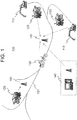
- Fig. 1 is a schematic configuration diagram of a road surface management system 100 according to the embodiment.
- the road surface management system 100 includes working vehicles 110, haulage vehicles 120, repair vehicles 130, a management server 140 and radio relay stations 150. It is noted that any number of the working vehicles 110, haulage vehicles 120, repair vehicles 130 and radio relay stations 150 may be employed. In the embodiment, also, the road surface management system will be described as being used in a mine, by way of example.
- the working vehicle 110 may be, for example, an excavator or the like, which performs the excavation work, loading work and/or the like.
- the working vehicle 110 is located in a loading site in a mine.
- the haulage vehicle 120 may be, for example, a dump truck or the like, which is used for transport of excavated materials, such as crushed stone, soil and sand, etc. excavated by the working vehicle 110, from a loading site to a dumping site. For transport, the haulage vehicle 120 travels on a travel route 101 in the mine. The embodiment will be described below assuming that the haulage vehicle 120 is a dump truck 120.
- the dump truck 120 includes a haulage vehicle onboard terminal 121 (see Fig. 2B ).
- the repair vehicle 130 may be, for example, a motor grade, a bulldozer or the like.
- the travel route 101 is not paved. Because of this, the road surface conditions of the travel route 101 are degraded by repeatedly reciprocating travel of the heavy weight dump truck 120, by rainfall, and/or the like.
- the repair vehicle 130 is for repairing the road surface of the travel route 101 which has been degraded due to such circumstances. The embodiment will be described below assuming that the repair vehicle 130 is a motor grader 130.
- the motor grader 130 includes a repair vehicle onboard terminal 131 (see Fig. 4B ).
- the management server 140 is placed in an administration center in the mine.
- the management server 140 performs transmission and reception of data between the haulage vehicle onboard terminal 121 and the repair vehicle onboard terminal 131 via the radio relay station 150.
- the management server 140 processes the data received from the haulage vehicle onboard terminals 121 and the repair vehicle onboard terminals 131 for management of the road surface of the travel routes 101 in the mine.
- Fig. 2A is a side view of the outer appearance of the dump truck 120
- Fig. 2B is a functional block diagram of the haulage vehicle onboard terminal 121 included in the dump truck 120.
- the dump truck 120 includes a vehicle body 211, left and right front wheels 212, left and right rear wheels 213, a load body 214, a cab 215, left and right front-wheel suspensions 216, left and right rear-wheel suspensions 217, and various sensors 220.
- the haulage vehicle onboard terminal 121 is placed, for example, in the cab 215.
- the left and right front-wheel suspensions 216 are installed between the vehicle body 211 and the respective left and right front wheels 212.
- the left and right rear-wheel suspensions 217 are installed between the vehicle body 211 and the respective left and right rear wheels 213.
- the four suspensions 216, 217 are, for example, hydraulic cylinders.
- the various sensors 220 include, as illustrated in Fig. 2B , a speed sensor 221, an angle sensor 222 and a pressure sensor 224.
- the speed sensor 221 is installed on a shaft of each of the left and right front wheels 212 and the left and right rear wheels 213 to detect a rotational speed of the shaft in an independent manner.
- the angle sensor 222 is installed in the vehicle body 211 to detect an inclined angle of the vehicle body 211.
- a pendulum sensor, MEMS or the like is used for the angle sensor 222.
- the pressure sensor 224 is installed in each of the front-wheel suspensions 216 and the rear-wheel suspensions 217, and the pressure sensor 224 is a suspension pressure sensor to detect the pressure in the corresponding hydraulic cylinder. The detected pressure is output as a suspension pressure.
- the dump truck 120 in the embodiment further includes a satellite signal receiver 122.
- the satellite signal receiver 122 receives signals from a plurality of navigation satellites such as e.g. GPS (Global Positioning System) satellites and/or the like.
- GPS Global Positioning System
- the satellite signal receiver 122 is hereinafter referred to as a GPS receiver 122.
- a signal received from the navigation satellite is also referred to as a GPS signal.
- the haulage vehicle onboard terminal 121 is connected to the various sensors 220 and the GPS receiver 122, and the haulage vehicle onboard terminal 121 processes the data acquired by them before transmitting the data to the management server 140.
- the road surface conditions of the travel route 101 and a slip ratio are calculated, and then transmitted, together with the position information, to the management server 140.
- the haulage vehicle onboard terminal 121 includes, as illustrated in Fig. 2B , a self-location arithmetic section 231, an operating information data collection section 232, an operating information database (DB) 233, a wireless communication apparatus (first communication apparatus) 234, a road surface condition estimation section 235, and a road surface condition database (DB) 236.
- a self-location arithmetic section 231 includes, as illustrated in Fig. 2B , a self-location arithmetic section 231, an operating information data collection section 232, an operating information database (DB) 233, a wireless communication apparatus (first communication apparatus) 234, a road surface condition estimation section 235, and a road surface condition database (DB) 236.
- DB road surface condition database
- the self-location arithmetic section 231 is connected to the GPS receiver 122 and the operating information DB 233.
- the self-location arithmetic section 231 acquires a GPS signal received by the GPS receiver 122, and uses the GPS signal to calculate a self-location.
- GNSS Global Navigation Satellite System
- the calculated self-position data, together with a GPS signal reception time-of-day, is stored in the operating information DB 233.
- an available navigation satellite is not limited to the GPS satellite, and may be, for example, GLONASS, Galileo, a satellite positioning system such as QZSS (Quasi-Zenith Satellite System) or the like, or any combination thereof.
- GLONASS Global System for Mobile Communications
- Galileo Galileo
- QZSS Quadrature-Zenith Satellite System
- a self-location to be estimated is expressed as coordinate values of a predetermined coordinate system.
- the coordinate system may be, for example, a mine-specific coordinate system, or alternatively, a latitude-longitude coordinate system with coordinate values representing latitude and longitude may be used.
- a coordinate system used herein is hereinafter referred to simply as an "applicable coordinate system”.
- the GPS signal reception time-of-day is hereinafter referred to as an "acquisition time-of-day”.
- the operating information data collection section 232 is connected to the operating information DB 233 and the various sensors 220 installed in the respective portions of the dump truck 120.
- the operating information data collection section 232 collects, as operating information data, sensor signals detected from the respective portions of the dump truck 120 by the sensors 220.
- data collected as operating information data includes, for example, speed data for each wheel from the speed sensor 221, angle data from the angle sensor 222 and pressure data for each suspension from the pressure sensor 224 (hereinafter referred to as "suspension pressure data").
- each sensor signal and the GPS signal are acquired periodically at almost the same times-of-day. Then, the signal values (data), together with the acquisition times-of-day, are output to the operating information DB 233.
- the operating information DB 233 stores the self-location data and the operating information data which are collected by the self-location arithmetic section 231 and the operating information data collection section 232.
- the self-location data and the operating information data are stored in association with the acquisition times-of-day, respectively.
- the road surface condition estimation section 235 is connected to the operating information DB 233.
- the road surface condition estimation section 235 uses the operating information data stored in the operating information DB 233 to estimate road surface conditions of the travel route 101.
- the road surface condition estimation section 235 calculates a road surface condition quantity (road surface condition data) and a slip ratio as indexes representing the road surface conditions.
- the road surface condition estimation section 235 calculates a slip ratio by use of the speed data of the dump truck 120 acquired at the speed sensor 221.
- the speed data from the speed sensor 221 of the rear wheel 213 is used as a wheel speed of a drive wheel and the speed data from the speed sensor 221 of the front wheel 212 is used as a wheel speed of a driven wheel.
- the calculations of the road surface condition data h(t) and the slip ratio ⁇ (t) are not limited to the above approaches.
- the road surface condition data h(t) may be calculated by use of a ratio of the suspension pressure data at time-of-day t to the suspension pressure data during travel at a constant speed on a flat road surface (see, e.g., JP-A No. 2013-166425 ).
- maximum amplitude and a frequency of the suspension pressure data within a predetermined time period may be determined and the determined values may be used as the road surface condition data h(t) (see, e.g., WO2015/140966 ).
- the road surface condition data h(t) and the slip ratio ⁇ (1), which have been calculated, are stored in the road surface condition DB 236 in association with the acquisition time-of-day t of the operating information data used in the calculation, and with the self-location data acquired at the same time-of-day. It is noted that, if there is no self-location data acquired at the same time-of-day as the operating information data, the road surface condition data h(t) and the slip ratio ⁇ (t) may be stored in association with self-location data acquired at a closest time-of-day.
- Fig. 3B shows an example of the road surface condition DB 236.
- the road surface conditions DB 236 includes self-locations 236b, times-of-day 236c, road surface condition data 236d and slip ratios 236e. Further, a vehicle ID uniquely assigned to each dump truck 120 may be included.
- the wireless communication apparatus 234 performs transmission/reception of data to/from the management server 140.
- the wireless communication apparatus 234 is connected to the road surface condition DB 236, and every time new data is stored in the road surface condition DB 236, the new data is transmitted as haulage vehicle data to the management server 140. It is noted that the haulage vehicle data may be transmitted periodically or in response to a request from the management server 140.
- Fig. 3B shows an example of haulage vehicle data 237 transmitted from the dump truck 120 to the management server 140.
- the haulage vehicle data 237 include a vehicle ID 237a, self-location data 237b, a time-of-day 237c, road surface conditions 237d and a slip ratio 237e.
- the wireless communication apparatus 234 may be also connected to the operating information DB 233, and may output the data stored in the operating information DB 233 to the management server 140 in a periodical manner or in response to a request from the management server 140.
- the haulage vehicle onboard terminal 121 is realized by, for example, a general-purpose information processing apparatus including a first arithmetic apparatus (CPU) 123, memory, a first storage apparatus 124, and a communication interface (wireless communication apparatus 234).
- the first arithmetic apparatus 123 loads and executes the program pre-stored in the first storage apparatus 124, into the memory in order to implement the self-location arithmetic section 231, the operating information data collection section 232 and the road surface condition estimation section 235.
- the operating information DB 233 and the road surface condition DB 236 are stored in the first storage apparatus 124.
- the haulage vehicle onboard terminal 121 may also include a display and a display control section for displaying process contents.
- Fig. 4A is a side view of the outer appearance of the motor grader 130
- Fig. 4B is a functional block diagram of the repair vehicle onboard terminal 131 included in the motor grader 130.
- the motor grader 130 includes a blade 311 and the blade actuator 312 to drive the blade.
- the motor grader 130 also includes, as sensors 320, a speed sensor 321, an angle sensor 322 and a blade angle sensor 323, as illustrated in Fig. 4B .
- the motor grader 130 also includes a satellite signal receiver (GPS receiver) 132 to receive signals from navigation satellites.
- GPS receiver satellite signal receiver
- the repair vehicle onboard terminal 131 is placed, for example, in a cab.
- the repair vehicle onboard terminal 131 is connected to the sensors 320 and the GPS receiver 122, and processes data acquired by them before transmitting the data to the management server 140.
- the repair vehicle onboard terminal 131 further detects whether or not the motor grader 130 has performed repair work, and then transmits the detection result (work status data) and self-location data to the management server 140.
- the repair vehicle onboard terminal 131 includes, as illustrated in Fig. 4B , a self-location arithmetic section 331, an operating information data collection section 332, an operating information database (DB) 333, a wireless communication apparatus (second communication apparatus) 334, a work status estimation section 335, and a work status database (DB) 336.
- a self-location arithmetic section 331 an operating information data collection section 332, an operating information database (DB) 333, a wireless communication apparatus (second communication apparatus) 334, a work status estimation section 335, and a work status database (DB) 336.
- the self-location arithmetic section 331, operating information data collection section 332, operating information DB 333, and wireless communication apparatus 334 are basically identical in function with the identically named sections of the haulage vehicle onboard terminal 121, and therefore, here, details of them are omitted.
- the wireless communication apparatus 334 is connected to the work status DB 336, and transmits later-described repair vehicle data to the management server 140.
- the work status estimation section 335 acquires information about whether or not the motor grader 130 is during execution of work.
- the work status estimation section 335 is connected to the operating information DB 333, and determines whether or not it is a working state, on the basis of sensor signals (operating information data) acquired and stored from the angle sensor 322 and the blade angle sensor 323.
- the work status estimation section 335 uses, for example, such operating information data to calculate, as a three-dimensional position, a height level of a leading end of a bottom side of the blade 311. If the calculation result becomes equal to or less than a predetermined height threshold valve, the working state is determined. The determination result is stored as work status data in the work status DB 336 in association with the acquisition time-of-day of the operating information data used in the calculation, and with the self-location data acquired at the same time-of-day, as in the case of the above-described road surface condition data.
- the work status estimation section 335 also calculates a slip ratio by use of the speed data acquired at the speed sensor 221, as in the case of the road surface condition estimation section 235 of the dump truck 120.
- Fig. 3C shows an example of the work status DB 336.
- the work status DB 336 includes self-locations 336b, times-of-day 336c, work status data 336d and slip ratios 336e.
- a vehicle ID uniquely assigned to each motor grader 130 may be included. It is noted that, by way of illustration only, the work status data 336d is illustrated as 1 being stored in the case of determining that it is the working state, and 0 being stored in other cases.
- Fig. 3D shows an example of repair vehicle data 337 transmitted from the motor grader 130 in the embodiment to the management server 140.
- the repair vehicle data 337 include a vehicle ID 337a, self-location 337b, a time-of-day 337c, work status data 337d and a slip ratio 337e.
- the repair vehicle onboard terminal 131 is realized by a general-purpose information processing apparatus including a second arithmetic apparatus (CPU) 133, memory, a second storage apparatus 134, and a communication interface (wireless communication apparatus 334).
- the second arithmetic apparatus 133 loads and executes the program pre-stored in the second storage apparatus 134, into the memory in order to implement the self-location arithmetic section 331, operating information data collection section 332 and work status estimation section 335.
- the operating information DB 333 and work status DB 336 are stored in the second storage apparatus 134.
- the repair vehicle onboard terminal 131 may also include a display and a display control section for displaying process contents.
- both of the dump truck 120 and the motor grader 130 will be hereinafter referred to simply as “vehicles” unless distinction between them is necessary. Also both of the haulage vehicle data 237 and the repair vehicle data 337 will also be referred to simply as “vehicle data” unless distinction between them is necessary.
- Fig. 5 is a functional block diagram of the management server 140 according to the embodiment.
- the management server 140 uses the haulage vehicle data transmitted from each of the dump trucks 120 and each of the motor graders 130, to calculate a prediction function that can provide a grasp of an appearance of changes in road surface conditions, and then presents the result to an administrator. Further, the management server 140 uses the prediction function to calculate the subsequent repair scheduled time-of-day, and then presents the result to the administrator. It is noted that the travel route 101 is divided into a plurality of regions (segments) and the prediction function and the repair scheduled time-of-day are calculated for each segment.
- the management server 140 includes a wireless communication apparatus 450, a data distribution section 410, a road surface condition arithmetic section 420, a storage apparatus 430 and a display apparatus 440.
- the road surface condition arithmetic section 420 estimates a current value of the road surface conditions, a mean value, a degradation rate and the like for each segment.
- the road surface condition arithmetic section 420 includes a prediction function calculation section 422, a repair timing estimation section 423, and a reset section 424.
- the storage apparatus 430 stores a travel route DB 431, a road surface DB 432 and an estimation value DB 433.
- the display apparatus 440 includes a display control section 441 and a display 442.
- the wireless communication apparatus 450 is a communication interface receiving via the radio relay stations 150 vehicle data which is transmitted from the dump trucks 120 and the motor graders 130. In the embodiment, the received vehicle data is output to the data distribution section 410.
- the travel route DB 431 stores the position data on the travel routes 101 in the entire mine on a segment-by-segment basis. For example, as illustrated in Fig. 6A , a range specified with coordinate values of the applicable coordinate system is stored on a segment-by-segment basis. It is noted that the position data on the travel route 101 for each segment may be decided, for example, based on data transmitted from a dump truck 120 while the dump truck 120 travels forward and backward along the travel route 101 over several times.
- the road surface DB 432 stores the vehicle data received from each vehicle on a segment-by-segment basis.
- a storage area is provided on a segment-by-segment basis.
- the storage areas of each database provided on a segment-by-segment basis will be hereinafter referred to as "segment storage areas”.
- the estimation value DB 433 stores an estimation value calculated for each segment by the road surface condition arithmetic section 420.
- the estimation values are, for example, a current value of the road surface conditions in each segment, a mean value, a degradation rate, and the like.
- the data distribution section 410 is connected to the wireless communication apparatus 450 and the travel route DB 431.
- the vehicle data on each vehicle received via the wireless communication apparatus 450 is stored in the road surface DB 432 on a segment-by-segment basis in which the sender vehicle is located. It is determined, based on the self-location data in the vehicle data, which segment the sender vehicle is located in.
- the prediction function calculation section 422 is connected to the road surface DB 432 and the estimation value DB 433. And, the prediction function calculation section 422 calculates a prediction function on the basis of the road surface condition data accumulated in the road surface DB 432. The prediction function is calculated for each segment.
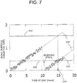
- the prediction function calculation section 422 plots the road surface data accumulated in a specific-segment area of the road surface date DB 432, as illustrated in Fig. 7 .
- the horizon axis of the graph in Fig. 7 represents times-of-day [hours], and the vertical axis represents the road surface condition data.
- the prediction function calculation section 422 performs fitting on the plot result by, for example, the method of least squares or the like in order to decide an approximate function as a prediction function 510. Then, a coefficient of the decided prediction function 510 is stored as an estimation value in a storage area provided in the estimation value DB 433 for a segment of interest for processing.
- the prediction function calculation section 422 approximates the plot result by a linear function.
- a coefficient stored as an estimation value is the slope of the function.
- the slope expresses a degradation rate.
- the prediction function calculation section 422 stores a latest value of the road surface condition data entered into the road surface DB 432 in the estimation value DB 433, as a current value 520 of the road surface conditions. Further, a mean value 550 of the latest multiple pieces of road surface condition data, or, a weighted mean value may be entered as a current value of the road surface situation.
- the prediction function calculation section 422 may also store all the road surface condition data used in the prediction function calculation in the estimation value DB 433, in association with times-of-day.
- the repair timing estimation section 423 is connected to the estimation value DB 433.
- the prediction function 510 calculated by the prediction function calculation section 422 is used to estimate a repair scheduled time-of-day 530 as repair timing for each segment.
- a road surface repair threshold value 540 is previously determined and the prediction function is extrapolated in order to estimate a time-of-day at which a value of the road surface condition data exceeds the road surface repair threshold value.
- the repair scheduled time-of-day thus calculated is stored in the estimation value DB 433.
- the reset section 424 is connected to the road surface DB 432 and the estimation value DB 433, and resets (discards) the accumulated data.
- the reset section 424 resets all the road surface condition data accumulated up to this point of time in the segment area. Also, the reset section 424 stores zero as a current value in association with the acquisition time-of-day of the working state data in the estimation value DB 433.
- the prediction function calculation section 422 calculates a prediction function 510 by use of only another road surface condition data accumulated subsequently to that, as illustrated in Fig. 7 . This is because, if the working state data is entered, the pertinent segment of the travel route 101 is considered to be levelled by the repair work executed by the motor grader 130, and therefore the road surface conditions are considered to result in initial conditions.
- the reset section 424 resets the road surface condition data in all the segment areas.
- Vehicle data with a slip ratio ⁇ (t) not less than the threshold value is output from a plurality of vehicles. This is considered because the road surface conditions of the travel route 101 have been significantly changed by external factors such as rainfall and/or the like.
- the display control section 441 is connected to the estimation value DB 433.
- the display control section 441 uses the estimation values stored in the estimation value DB 433 to generate display data to be displayed on the display 442, and then causes the display 442 to display the display data.
- the display data includes, for example, the road surface condition data illustrated in Fig. 7 , prediction function 510, current value 520, mean value 550, and repair scheduled time-of-day 530.
- management server 140 may be configured to include further a sound output section to provide a sound notification of the repair scheduled time-of-day 530.
- the management server 140 is realized by, for example, an information processing apparatus including a CPU (arithmetic apparatus) 460, memory, a storage apparatus 430, a communication interface (wireless communication apparatus 450), and an output apparatus (display apparatus 440).
- the arithmetic apparatus 460 loads and executes the program pre-stored in the storage apparatus 430, into the memory in order to implement the data distribution section 410, road surface condition arithmetic section 420 and display control section 441.
- the travel route DB 431, road surface DB 432, and estimation value DB 433 are stored in the storage apparatus 430.
- Fig. 8 is a processing flow of the road surface management processing according to the embodiment. In the following, assuming that vehicle data is received at substantially the same time-of-day from M vehicles (M is an integer not less than one).
- the data distribution section 410 compares the self-location data and the coordinates in the travel route DB 431 to determine a segment in which a sender vehicle pertinent to the vehicle data of interest for processing is located (step S1102), and stores the road surface condition data of the pertinent segment number in a corresponding segment area of the road surface DB 432 (step S1103).
- the reset section 424 determines whether or not the slip ratio in the vehicle data entered into the road surface DB 432 is equal to or less than the slip ratio threshold value ⁇ th (step S1104).
- step S1102 If the slip ratio is equal to or less than the slip ratio threshold value ⁇ th (S1104; Yes), the flow returns to step S1102 to process the subsequent vehicle data (steps S1105, 1106).
- the road surface condition arithmetic section 420 counts the number of segments newly entered, exclusive of overlaps, and the resulting count is defined as K (K is an integer not less than one) (step S1110). Then, the road surface condition arithmetic section 420 performs the road surface condition arithmetic processing (step S1111), and then the processing is terminated.
- the vehicles threshold value Nth is set to a value suitable for such determination.
- the vehicles threshold value Nth is set to 40% or half of the total number of vehicles, or the like.
- step S1105 If the number of high slip ratio vehicles is below the vehicles threshold value Nth (S1108; No), the flow moves to step S1105 to continue the processing.
- step S1108 if the number of high slip ratio vehicles reaches the vehicles threshold value Nth (Yes), the reset section 424 sets a slip flag (step S1109), and then the flow moves to S1111.
- Fig. 9 is a processing flow of the road surface condition arithmetic processing according to the embodiment.
- the road surface condition arithmetic processing is performed on only the segment pertinent to new data entered into the road surface DB 432.
- the number of segments pertinent to the newly entered data is K.
- the road surface condition arithmetic section 420 determines whether or not the slip flag is set (step S1201).
- the road surface condition arithmetic section 420 determines whether or not a sender of the vehicle data newly entered is a dump truck 120 (step S2103). The determination is made by using a vehicle ID in the vehicle data.
- the prediction function calculation section 422 decides a prediction function by use of the entire vehicle data accumulated in the pertinent segment area of the road surface data DB 432 (step S2104).
- the prediction function calculation section 422 obtains a coefficient of the calculated prediction function as a degradation rate. Also, the entire vehicle data accumulated in the pertinent segment area is used to calculate a mean value (step S2105). For example, where the prediction function is a linear function, the slope is used for the degradation rate.
- the prediction function calculation section 422 extrapolates the prediction function to estimate a repair scheduled time-of-day (step S2106).
- the prediction function calculation section 422 stores estimation values of the calculated mean value, degradation rate, repair scheduled time-of-day and the like, in the estimation value DB 433 (step S2107).
- the display control section 441 uses the data stored in the estimation value DB 433 to generate display image data, and then causes the display 442 to display it to perform an update of display on the display 442 (step S2108).
- step S2103 if it is determined that the sender is a motor grader 130, the reset section 424 determines whether or not the working state has been entered as work status data (step S2111). In the case of the no-working state, the flow moves directly to step S2108.
- step S2111 the working state has been entered
- the reset section 424 performs the reset processing to reset the entire road surface condition data on the segment currently processed (step S2112), and stores zero as the road surface condition data in the estimation value DB 433, and then the flow moves to step S2108.
- the road surface condition arithmetic section 420 repeatedly performs the above-described processing on all the segments pertinent to the newly entered data (steps S2109, S2110), and the processing is terminated.
- step S2101 the slip flag is set (Yes)
- the reset section 424 performs the reset processing to reset the road surface condition data on all the segments in the road surface DB 432 (step S2121). At this time, the reset section 424 stores zero as the road surface condition data in each segment of the estimation value DB 433.
- the display control section 441 generates display image data for all the segments by use of the data stored in the estimation value DB 433 after reset processing, and then causes the display 442 to display it to perform an update of display on the display 442 (step S2123), and then the processing is terminated.
- the haulage vehicle onboard terminals 121, the repair vehicle onboard terminals 131 and the management server 140 are included.
- the haulage vehicle onboard terminal 121 is installed in a dump truck 120 and periodically transmits: self-location data indicating a location of the dump truck 120; road surface condition data on the travel route 101 of the dump truck 120; and a slip ratio of the dump truck 120.
- the repair vehicle onboard terminal 131 is installed in a motor grader 130 and periodically transmits: self-location data indicating a location of the motor grader 130; work status data; and a slip ratio of the motor grader 130.
- the management server 140 divides the travel route 101 along which the dump truck 120 travels, into a plurality of segments, and manages the road surface conditions of the travel route 101 on a segment-by-segment basis.
- the management server 140 associates a segment including the location specified by the self-location data, a reception time-of-day, and the road surface condition data with one another, and then accumulates them in the road surface DB 432. Also, every time the self-location data and the work status data indicating "the working state" are received from the motor grader 130, the management server 140 resets all the pieces of the road surface condition data concerning the segment which includes a location specified by this self-location data, the road surface condition data being accumulated in the road surface DB 432.
- the management server 140 determines, based on a plurality of pieces of the road surface condition data accumulated on a segment-by-segment basis, a prediction function to predict a chronological change in the road surface conditions of the segment. Then, the management server 140 calculates, according to the determined prediction function, a time to reach the road surface repair threshold value as a repair scheduled time-of-day. Then, the management server 140 outputs the calculation result to the output apparatus.
- a prediction function to predict a change in road surface conditions is determined by taking into account not only the road surface condition data transmitted from the haulage vehicle such as the dump truck 120, but also the work status data transmitted from the repair vehicle such as the motor grader 130.
- repair times are predicted based on the determined prediction function. This enables high-accurate prediction in line with more actual circumstances. Then, the administrator can make a repair plan based on the high-accurate prediction. As a result, a strategic, high-accurate road-surface maintenance plan can be made, and therefore efficient road surface management can be implemented.
- a slip ratio is received from each vehicle and also variability of the slip ratio data is monitored. Then, at the same time of day, if the slip ratios from a predefined number or greater predefined number of vehicles exceed a predetermined value, the prediction function is reset. This is because higher slip ratios of the predetermined number or greater predetermined number of vehicles at the same time-of-day mean that it rains. And, in this case, the prediction functions for throughout the mine are reset.
- the changed conditions of the road surface are determined by taking into account not only the road surface condition data, but also the slip ratios. Because of this, even when the road surface conditions are significantly changed by a change in weather, for example, rainfall and/or the like, appropriate measures can be taken.
- all of the road surface condition data, the slip ratio and the work status data are calculated on the vehicle and then are transmitted to the management server 140.
- the self-location data, acquisition time and operating information data may be transmitted from the vehicle to the management server 140 and then the management server 140 may use these data for calculations.
- the repair prediction time is displayed on the display 442 to provide notification to the administrator.
- the manner of providing notification to the administrator is not limited to this.
- a sound notification or the like may be configured to be provided.
Landscapes
- Business, Economics & Management (AREA)
- Engineering & Computer Science (AREA)
- Human Resources & Organizations (AREA)
- Physics & Mathematics (AREA)
- General Physics & Mathematics (AREA)
- Economics (AREA)
- Strategic Management (AREA)
- Tourism & Hospitality (AREA)
- Marketing (AREA)
- Theoretical Computer Science (AREA)
- General Business, Economics & Management (AREA)
- Operations Research (AREA)
- Quality & Reliability (AREA)
- Entrepreneurship & Innovation (AREA)
- General Health & Medical Sciences (AREA)
- Primary Health Care (AREA)
- Health & Medical Sciences (AREA)
- Structural Engineering (AREA)
- Civil Engineering (AREA)
- Architecture (AREA)
- Marine Sciences & Fisheries (AREA)
- Mining & Mineral Resources (AREA)
- Animal Husbandry (AREA)
- Agronomy & Crop Science (AREA)
- Life Sciences & Earth Sciences (AREA)
- Development Economics (AREA)
- Game Theory and Decision Science (AREA)
- Traffic Control Systems (AREA)
- Road Repair (AREA)
- Management, Administration, Business Operations System, And Electronic Commerce (AREA)
Abstract
Description
- The present invention relates to a technique for managing road surface conditions of a travel route of a haulage vehicle. In particular, the present invention relates to a technique for managing road surface conditions of an unpaved travel route such as in a mine and the like.
- There is a technology to implement the maintenance management of the road surface which is degraded by haulage vehicles repeatedly traveling on unpaved travel routes such as in a mine excavation site or the like. For example,
Patent Literature 1 discloses a mine machinery management system "in which a management apparatus gathers operating information about dump trucks via a management wireless communication apparatus. Routes Rg, Rr along which a dump truck travels are identified based on position information on at least four places included in the operating information about a dump truck, the four places being included in a route of the dump truck moving from a dumping site to a loading site where the truck is loaded, and then moving back to the dumping site (excerpts from an abstract)". - PATENT LITERATURE 1:
JP-A No. 2013-105278 - In the technology disclosed in
Patent Literature 1, a roughness of the road surface of the travel route identified by the above technique are sensed by use of the operating information about the dump truck in order to make a road-surface maintenance plan. However, in general, in environment as described above, maintenance vehicles for repairing the travel route, combined with the haulage vehicles, simultaneously travel in order to repair a place where the road surface conditions have been degraded. In the technique disclosed inPatent Literature 1, such repairs done by the maintenance vehicle are never taken into account. Further, factors contributing to the occurrence of the roughness include a time-related, local factor such as traveling of the haulage vehicles and an unexpected, global factor such as rainfall and/or the like. However, in the technique disclosed inPatent Literature 1, a difference between both the factors is never taken into account. For these reasons, the technique disclosed inPatent Literature 1 cannot provide a rational, high-precision plan to perform the road-surface maintenance. - The present invention has been achieved in view of such circumstances, and it is an object thereof to provide a technique for enabling efficient road surface management in environment where haulage vehicles repeatedly travel on unpaved travel routes such as in a mine or the like, in order to contribute to the enhanced efficiency of the road-surface maintenance work.
- The present invention provides a road surface management system which divides a travel route, along which a haulage vehicle travels, into a plurality of segments, and manages road surface conditions of the travel route on a segment-by-segment basis. The road surface management system includes: a management server that includes an arithmetic apparatus, a storage apparatus, an output apparatus and a communication apparatus; a haulage vehicle onboard terminal that is installed in the haulage vehicle and includes a first arithmetic apparatus and a first communication apparatus; and a repair vehicle onboard terminal that is installed in a repair vehicle for repairing the travel route, and includes a second arithmetic apparatus and a second communication apparatus. The first arithmetic apparatus calculates road surface condition data on the travel route on the basis of a signal input from a sensor installed in the haulage vehicle. The first arithmetic apparatus transmits the road surface condition data thus calculated, combined with haulage vehicle position data which is positional data of the haulage vehicle, to the management server through the first communication apparatus. The second arithmetic apparatus calculates work status data indicating a work status of the repair vehicle, on the basis of a signal input from a sensor installed in the repair vehicle. The second arithmetic apparatus transmits the work status data thus calculated, combined with repair vehicle position data which is positional data of the repair vehicle, to the management server through the second communication apparatus. The arithmetic apparatus is connected to the communication apparatus, the storage apparatus and the output apparatus. Every time the arithmetic apparatus receives the haulage vehicle position data and the road surface condition data through the communication apparatus, the arithmetic apparatus associates the segment including a position specified by the haulage vehicle position data, a reception time-of-day, and the road surface condition data with one another for accumulation in the storage apparatus. Every time the arithmetic apparatus receives the repair vehicle position data and the work status data indicating a working state, through the communication apparatus, the arithmetic apparatus resets the road surface condition data accumulated in the storage device in association with the segment including a position specified by the repair vehicle position data. Every time the road surface condition data is newly accumulated in the storage apparatus, the arithmetic apparatus determines a prediction function to predict a chronological change in road surface conditions of the segment on the basis of a plurality of pieces of the road surface condition data accumulated on a segment-by-segment basis. Then, according to the prediction function thus determined, the arithmetic apparatus calculates a time to reach a road surface repair threshold value as a repair scheduled time-of-day. The arithmetic apparatus outputs the repair scheduled time-of-day thus calculated, to the output apparatus.
- According to the present invention, in the environment where haulage vehicles repeatedly travel on unpaved travel routes such as in a mine or the like, efficient road surface management is enabled to contribute to the enhanced efficiency of the road-surface maintenance work. The above and other problems, configurations and advantageous effects will be more apparent from the following description of an embodiment.
-
-
Fig. 1 is an explanatory diagram for illustrating the overall configuration of a road surface management system according to an embodiment of the present invention. -
Fig. 2A is a side view of a dump truck of an embodiment according to the present invention, andFig. 2B is a functional block diagram of a haulage vehicle onboard terminal according to an embodiment of the present invention. -
Fig. 3B is an explanatory diagram for illustrating an example of a road surface condition database according to an embodiment of the present invention,Fig. 3B is an explanatory diagram for illustrating an example of haulage vehicle data according to the embodiment,Fig. 3C is an explanatory diagram for illustrating an example of work status data according to the embodiment, andFig. 3D is an explanatory diagram for illustrating an example of repair vehicle data according to the embodiment. -
Fig. 4A is a side view of a motor grader of an embodiment according to the present invention, andFig. 4B is a functional block diagram of a repair vehicle onboard terminal according to an embodiment of the present invention. -
Fig. 5 is a functional block diagram of a management server according to an embodiment of the present invention. -
Fig. 6A is an explanatory diagram for illustrating an example of a road route database according to an embodiment of the present invention, andFig. 6B is an explanatory diagram for illustrating an example of road surface database according to the embodiment. -
Fig. 7 is an explanatory diagram for illustrating prediction function calculation processing and a display image according to an embodiment of the present invention. -
Fig. 8 is a flowchart of road surface management processing according to an embodiment of the present invention. -
Fig. 9 is a flowchart of road surface condition arithmetic processing according to an embodiment of the present invention. - An embodiment according to the present invention will now be described with reference to the accompanying drawings. It is noted that, throughout the specification, like reference signs are used to refer to elements/components having like functions unless otherwise specified, and a repetitive description is omitted.
- A road surface management system according to the embodiment is mainly used in the environment where haulage vehicles repeatedly travel on unpaved travel routes such as in a mine or the like. The road surface management system according to the embodiment determines a road-surface condition prediction function by use of a set of position information and road surface information about a travel route received from a haulage vehicle, and a set of position information and work information received from a repair vehicle. The prediction function is then used to predict the repair timing which is then notified. At this time, independently of the determination of the prediction function, road surface changes by weather are also taken into consideration. The road surface management system according to the embodiment will be described below with an eye to the functions.
-
Fig. 1 is a schematic configuration diagram of a roadsurface management system 100 according to the embodiment. The roadsurface management system 100 according to the embodiment includesworking vehicles 110,haulage vehicles 120,repair vehicles 130, amanagement server 140 andradio relay stations 150. It is noted that any number of theworking vehicles 110,haulage vehicles 120,repair vehicles 130 andradio relay stations 150 may be employed. In the embodiment, also, the road surface management system will be described as being used in a mine, by way of example. - The working
vehicle 110 may be, for example, an excavator or the like, which performs the excavation work, loading work and/or the like. The workingvehicle 110 is located in a loading site in a mine. - The
haulage vehicle 120 may be, for example, a dump truck or the like, which is used for transport of excavated materials, such as crushed stone, soil and sand, etc. excavated by the workingvehicle 110, from a loading site to a dumping site. For transport, thehaulage vehicle 120 travels on atravel route 101 in the mine. The embodiment will be described below assuming that thehaulage vehicle 120 is adump truck 120. Thedump truck 120 includes a haulage vehicle onboard terminal 121 (seeFig. 2B ). - The
repair vehicle 130 may be, for example, a motor grade, a bulldozer or the like. In a mine, as described above, thetravel route 101 is not paved. Because of this, the road surface conditions of thetravel route 101 are degraded by repeatedly reciprocating travel of the heavyweight dump truck 120, by rainfall, and/or the like. Therepair vehicle 130 is for repairing the road surface of thetravel route 101 which has been degraded due to such circumstances. The embodiment will be described below assuming that therepair vehicle 130 is amotor grader 130. Themotor grader 130 includes a repair vehicle onboard terminal 131 (seeFig. 4B ). - The
management server 140 is placed in an administration center in the mine. Themanagement server 140 performs transmission and reception of data between the haulage vehicleonboard terminal 121 and the repair vehicleonboard terminal 131 via theradio relay station 150. In the embodiment, themanagement server 140 processes the data received from the haulage vehicleonboard terminals 121 and the repair vehicleonboard terminals 131 for management of the road surface of thetravel routes 101 in the mine. - Initially, the configuration of the
dump truck 120 is described.Fig. 2A is a side view of the outer appearance of thedump truck 120, andFig. 2B is a functional block diagram of the haulage vehicleonboard terminal 121 included in thedump truck 120. - As illustrated in
Fig. 2 , thedump truck 120 includes avehicle body 211, left and rightfront wheels 212, left and rightrear wheels 213, aload body 214, acab 215, left and right front-wheel suspensions 216, left and right rear-wheel suspensions 217, andvarious sensors 220. The haulage vehicleonboard terminal 121 is placed, for example, in thecab 215. - The left and right front-
wheel suspensions 216 are installed between thevehicle body 211 and the respective left and rightfront wheels 212. The left and right rear-wheel suspensions 217 are installed between thevehicle body 211 and the respective left and rightrear wheels 213. The foursuspensions - In the embodiment, the
various sensors 220 include, as illustrated inFig. 2B , aspeed sensor 221, anangle sensor 222 and apressure sensor 224. - The
speed sensor 221 is installed on a shaft of each of the left and rightfront wheels 212 and the left and rightrear wheels 213 to detect a rotational speed of the shaft in an independent manner. - The
angle sensor 222 is installed in thevehicle body 211 to detect an inclined angle of thevehicle body 211. For example, a pendulum sensor, MEMS or the like is used for theangle sensor 222. - The
pressure sensor 224 is installed in each of the front-wheel suspensions 216 and the rear-wheel suspensions 217, and thepressure sensor 224 is a suspension pressure sensor to detect the pressure in the corresponding hydraulic cylinder. The detected pressure is output as a suspension pressure. - The
dump truck 120 in the embodiment further includes asatellite signal receiver 122. Thesatellite signal receiver 122 receives signals from a plurality of navigation satellites such as e.g. GPS (Global Positioning System) satellites and/or the like. In the embodiment, thesatellite signal receiver 122 is hereinafter referred to as aGPS receiver 122. A signal received from the navigation satellite is also referred to as a GPS signal. - As illustrated in
Fig. 2B , the haulage vehicleonboard terminal 121 is connected to thevarious sensors 220 and theGPS receiver 122, and the haulage vehicle onboard terminal 121 processes the data acquired by them before transmitting the data to themanagement server 140. In addition, in the embodiment, the road surface conditions of thetravel route 101 and a slip ratio are calculated, and then transmitted, together with the position information, to themanagement server 140. - To realize this, the haulage vehicle
onboard terminal 121 according to the embodiment includes, as illustrated inFig. 2B , a self-location arithmetic section 231, an operating informationdata collection section 232, an operating information database (DB) 233, a wireless communication apparatus (first communication apparatus) 234, a road surfacecondition estimation section 235, and a road surface condition database (DB) 236. - The self-
location arithmetic section 231 is connected to theGPS receiver 122 and the operatinginformation DB 233. The self-location arithmetic section 231 acquires a GPS signal received by theGPS receiver 122, and uses the GPS signal to calculate a self-location. GNSS (Global Navigation Satellite System) is employed herein, which is a positioning scheme using GPS signals. The calculated self-position data, together with a GPS signal reception time-of-day, is stored in the operatinginformation DB 233. - It is noted that an available navigation satellite is not limited to the GPS satellite, and may be, for example, GLONASS, Galileo, a satellite positioning system such as QZSS (Quasi-Zenith Satellite System) or the like, or any combination thereof.
- In the embodiment, assuming that a self-location to be estimated is expressed as coordinate values of a predetermined coordinate system. The coordinate system may be, for example, a mine-specific coordinate system, or alternatively, a latitude-longitude coordinate system with coordinate values representing latitude and longitude may be used. A coordinate system used herein is hereinafter referred to simply as an "applicable coordinate system". Also, the GPS signal reception time-of-day is hereinafter referred to as an "acquisition time-of-day".
- The operating information
data collection section 232 is connected to the operatinginformation DB 233 and thevarious sensors 220 installed in the respective portions of thedump truck 120. The operating informationdata collection section 232 collects, as operating information data, sensor signals detected from the respective portions of thedump truck 120 by thesensors 220. In the embodiment, data collected as operating information data includes, for example, speed data for each wheel from thespeed sensor 221, angle data from theangle sensor 222 and pressure data for each suspension from the pressure sensor 224 (hereinafter referred to as "suspension pressure data"). - Note that in the embodiment it is assumed that each sensor signal and the GPS signal are acquired periodically at almost the same times-of-day. Then, the signal values (data), together with the acquisition times-of-day, are output to the operating
information DB 233. - The operating
information DB 233 stores the self-location data and the operating information data which are collected by the self-location arithmetic section 231 and the operating informationdata collection section 232. In the embodiment, the self-location data and the operating information data are stored in association with the acquisition times-of-day, respectively. - The road surface
condition estimation section 235 is connected to the operatinginformation DB 233. The road surfacecondition estimation section 235 uses the operating information data stored in the operatinginformation DB 233 to estimate road surface conditions of thetravel route 101. In the embodiment, the road surfacecondition estimation section 235 calculates a road surface condition quantity (road surface condition data) and a slip ratio as indexes representing the road surface conditions. - In the embodiment, the road surface
condition estimation section 235 calculates the road surface condition data by use of the speed data and the suspension pressure data of thedump truck 120. Specifically, the above data acquired at time-of-day t is used to calculate the road surface condition data h(t) on the basis of the following equation (1):
- Further, the road surface
condition estimation section 235 calculates a slip ratio by use of the speed data of thedump truck 120 acquired at thespeed sensor 221. Specifically, for example, the above data acquired at time-of-day t is used to calculate a slip ratio λ(t) on the basis of the following equation (2):
5336447 speed sensor 221 of therear wheel 213 is used as a wheel speed of a drive wheel and the speed data from thespeed sensor 221 of thefront wheel 212 is used as a wheel speed of a driven wheel. - It is noted that the calculations of the road surface condition data h(t) and the slip ratio λ(t) are not limited to the above approaches. For example, the road surface condition data h(t) may be calculated by use of a ratio of the suspension pressure data at time-of-day t to the suspension pressure data during travel at a constant speed on a flat road surface (see, e.g.,
JP-A No. 2013-166425 WO2015/140966 ). - The road surface condition data h(t) and the slip ratio λ(1), which have been calculated, are stored in the road
surface condition DB 236 in association with the acquisition time-of-day t of the operating information data used in the calculation, and with the self-location data acquired at the same time-of-day. It is noted that, if there is no self-location data acquired at the same time-of-day as the operating information data, the road surface condition data h(t) and the slip ratio λ(t) may be stored in association with self-location data acquired at a closest time-of-day. - Here,
Fig. 3B shows an example of the roadsurface condition DB 236. As illustrated inFig. 3B , the roadsurface conditions DB 236 includes self-locations 236b, times-of-day 236c, roadsurface condition data 236d and slipratios 236e. Further, a vehicle ID uniquely assigned to eachdump truck 120 may be included. - The
wireless communication apparatus 234 performs transmission/reception of data to/from themanagement server 140. In the embodiment, thewireless communication apparatus 234 is connected to the roadsurface condition DB 236, and every time new data is stored in the roadsurface condition DB 236, the new data is transmitted as haulage vehicle data to themanagement server 140. It is noted that the haulage vehicle data may be transmitted periodically or in response to a request from themanagement server 140. -
Fig. 3B shows an example ofhaulage vehicle data 237 transmitted from thedump truck 120 to themanagement server 140. As illustrated inFig. 3B , thehaulage vehicle data 237 include avehicle ID 237a, self-location data 237b, a time-of-day 237c,road surface conditions 237d and aslip ratio 237e. - It is noted that the
wireless communication apparatus 234 may be also connected to the operatinginformation DB 233, and may output the data stored in the operatinginformation DB 233 to themanagement server 140 in a periodical manner or in response to a request from themanagement server 140. - The haulage vehicle
onboard terminal 121 according to the embodiment is realized by, for example, a general-purpose information processing apparatus including a first arithmetic apparatus (CPU) 123, memory, afirst storage apparatus 124, and a communication interface (wireless communication apparatus 234). The firstarithmetic apparatus 123 loads and executes the program pre-stored in thefirst storage apparatus 124, into the memory in order to implement the self-location arithmetic section 231, the operating informationdata collection section 232 and the road surfacecondition estimation section 235. The operatinginformation DB 233 and the roadsurface condition DB 236 are stored in thefirst storage apparatus 124. - The haulage vehicle
onboard terminal 121 may also include a display and a display control section for displaying process contents. - Next, a
motor grader 130 will be described.Fig. 4A is a side view of the outer appearance of themotor grader 130, andFig. 4B is a functional block diagram of the repair vehicleonboard terminal 131 included in themotor grader 130. - The
motor grader 130 according to the embodiment includes ablade 311 and theblade actuator 312 to drive the blade. Themotor grader 130 also includes, assensors 320, aspeed sensor 321, anangle sensor 322 and ablade angle sensor 323, as illustrated inFig. 4B . Similarly to thedump truck 120, themotor grader 130 also includes a satellite signal receiver (GPS receiver) 132 to receive signals from navigation satellites. Further, the repair vehicleonboard terminal 131 is placed, for example, in a cab. - As illustrated in
Fig. 3B , the repair vehicleonboard terminal 131 is connected to thesensors 320 and theGPS receiver 122, and processes data acquired by them before transmitting the data to themanagement server 140. In the embodiment, the repair vehicleonboard terminal 131 further detects whether or not themotor grader 130 has performed repair work, and then transmits the detection result (work status data) and self-location data to themanagement server 140. - To realize this, the repair vehicle
onboard terminal 131 according to the embodiment includes, as illustrated inFig. 4B , a self-location arithmetic section 331, an operating informationdata collection section 332, an operating information database (DB) 333, a wireless communication apparatus (second communication apparatus) 334, a workstatus estimation section 335, and a work status database (DB) 336. - The self-
location arithmetic section 331, operating informationdata collection section 332, operatinginformation DB 333, andwireless communication apparatus 334 are basically identical in function with the identically named sections of the haulage vehicleonboard terminal 121, and therefore, here, details of them are omitted. However, thewireless communication apparatus 334 is connected to thework status DB 336, and transmits later-described repair vehicle data to themanagement server 140. - The work
status estimation section 335 acquires information about whether or not themotor grader 130 is during execution of work. In the embodiment, the workstatus estimation section 335 is connected to the operatinginformation DB 333, and determines whether or not it is a working state, on the basis of sensor signals (operating information data) acquired and stored from theangle sensor 322 and theblade angle sensor 323. - The work
status estimation section 335 uses, for example, such operating information data to calculate, as a three-dimensional position, a height level of a leading end of a bottom side of theblade 311. If the calculation result becomes equal to or less than a predetermined height threshold valve, the working state is determined. The determination result is stored as work status data in thework status DB 336 in association with the acquisition time-of-day of the operating information data used in the calculation, and with the self-location data acquired at the same time-of-day, as in the case of the above-described road surface condition data. - The work
status estimation section 335 according to the embodiment also calculates a slip ratio by use of the speed data acquired at thespeed sensor 221, as in the case of the road surfacecondition estimation section 235 of thedump truck 120. - Here,
Fig. 3C shows an example of thework status DB 336. As illustrated inFig. 3C , thework status DB 336 includes self-locations 336b, times-of-day 336c,work status data 336d and slipratios 336e. Further, a vehicle ID uniquely assigned to eachmotor grader 130 may be included. It is noted that, by way of illustration only, thework status data 336d is illustrated as 1 being stored in the case of determining that it is the working state, and 0 being stored in other cases. - Also,
Fig. 3D shows an example ofrepair vehicle data 337 transmitted from themotor grader 130 in the embodiment to themanagement server 140. As illustrated inFig. 3D , therepair vehicle data 337 include avehicle ID 337a, self-location 337b, a time-of-day 337c,work status data 337d and aslip ratio 337e. - Similarly to the haulage vehicle
onboard terminal 121, the repair vehicleonboard terminal 131 is realized by a general-purpose information processing apparatus including a second arithmetic apparatus (CPU) 133, memory, asecond storage apparatus 134, and a communication interface (wireless communication apparatus 334). The secondarithmetic apparatus 133 loads and executes the program pre-stored in thesecond storage apparatus 134, into the memory in order to implement the self-location arithmetic section 331, operating informationdata collection section 332 and workstatus estimation section 335. The operatinginformation DB 333 andwork status DB 336 are stored in thesecond storage apparatus 134. - The repair vehicle
onboard terminal 131 may also include a display and a display control section for displaying process contents. - Both of the
dump truck 120 and themotor grader 130 will be hereinafter referred to simply as "vehicles" unless distinction between them is necessary. Also both of thehaulage vehicle data 237 and therepair vehicle data 337 will also be referred to simply as "vehicle data" unless distinction between them is necessary. - Next, the management server 40 will be described.
Fig. 5 is a functional block diagram of themanagement server 140 according to the embodiment. - In the embodiment, the
management server 140 uses the haulage vehicle data transmitted from each of thedump trucks 120 and each of themotor graders 130, to calculate a prediction function that can provide a grasp of an appearance of changes in road surface conditions, and then presents the result to an administrator. Further, themanagement server 140 uses the prediction function to calculate the subsequent repair scheduled time-of-day, and then presents the result to the administrator. It is noted that thetravel route 101 is divided into a plurality of regions (segments) and the prediction function and the repair scheduled time-of-day are calculated for each segment. - To realize this, the
management server 140 according to the embodiment includes awireless communication apparatus 450, a data distribution section 410, a road surface conditionarithmetic section 420, astorage apparatus 430 and adisplay apparatus 440. - The road surface condition
arithmetic section 420 estimates a current value of the road surface conditions, a mean value, a degradation rate and the like for each segment. For this purpose, the road surface conditionarithmetic section 420 includes a predictionfunction calculation section 422, a repairtiming estimation section 423, and areset section 424. Also, thestorage apparatus 430 stores atravel route DB 431, aroad surface DB 432 and anestimation value DB 433. Thedisplay apparatus 440 includes adisplay control section 441 and adisplay 442. - The
wireless communication apparatus 450 is a communication interface receiving via theradio relay stations 150 vehicle data which is transmitted from thedump trucks 120 and themotor graders 130. In the embodiment, the received vehicle data is output to the data distribution section 410. - The
travel route DB 431 stores the position data on thetravel routes 101 in the entire mine on a segment-by-segment basis. For example, as illustrated inFig. 6A , a range specified with coordinate values of the applicable coordinate system is stored on a segment-by-segment basis. It is noted that the position data on thetravel route 101 for each segment may be decided, for example, based on data transmitted from adump truck 120 while thedump truck 120 travels forward and backward along thetravel route 101 over several times. - As illustrated in
Fig. 6B , theroad surface DB 432 stores the vehicle data received from each vehicle on a segment-by-segment basis. A storage area is provided on a segment-by-segment basis. The storage areas of each database provided on a segment-by-segment basis will be hereinafter referred to as "segment storage areas". - The
estimation value DB 433 stores an estimation value calculated for each segment by the road surface conditionarithmetic section 420. As described later, the estimation values are, for example, a current value of the road surface conditions in each segment, a mean value, a degradation rate, and the like. - The data distribution section 410 is connected to the
wireless communication apparatus 450 and thetravel route DB 431. The vehicle data on each vehicle received via thewireless communication apparatus 450 is stored in theroad surface DB 432 on a segment-by-segment basis in which the sender vehicle is located. It is determined, based on the self-location data in the vehicle data, which segment the sender vehicle is located in. - The prediction
function calculation section 422 is connected to theroad surface DB 432 and theestimation value DB 433. And, the predictionfunction calculation section 422 calculates a prediction function on the basis of the road surface condition data accumulated in theroad surface DB 432. The prediction function is calculated for each segment. - Specifically, for example, the prediction
function calculation section 422 plots the road surface data accumulated in a specific-segment area of the roadsurface date DB 432, as illustrated inFig. 7 . The horizon axis of the graph inFig. 7 represents times-of-day [hours], and the vertical axis represents the road surface condition data. - Then, the prediction
function calculation section 422 performs fitting on the plot result by, for example, the method of least squares or the like in order to decide an approximate function as aprediction function 510. Then, a coefficient of the decidedprediction function 510 is stored as an estimation value in a storage area provided in theestimation value DB 433 for a segment of interest for processing. - For example, in the example of
Fig. 7 , the predictionfunction calculation section 422 approximates the plot result by a linear function. A coefficient stored as an estimation value is the slope of the function. In this case, the slope expresses a degradation rate. - It is noted that the prediction
function calculation section 422 stores a latest value of the road surface condition data entered into theroad surface DB 432 in theestimation value DB 433, as acurrent value 520 of the road surface conditions. Further, amean value 550 of the latest multiple pieces of road surface condition data, or, a weighted mean value may be entered as a current value of the road surface situation. - The prediction
function calculation section 422 may also store all the road surface condition data used in the prediction function calculation in theestimation value DB 433, in association with times-of-day. - The repair
timing estimation section 423 is connected to theestimation value DB 433. Theprediction function 510 calculated by the predictionfunction calculation section 422 is used to estimate a repair scheduled time-of-day 530 as repair timing for each segment. For estimating the repair scheduled time-of-day, for example, a road surfacerepair threshold value 540 is previously determined and the prediction function is extrapolated in order to estimate a time-of-day at which a value of the road surface condition data exceeds the road surface repair threshold value. The repair scheduled time-of-day thus calculated is stored in theestimation value DB 433. - The
reset section 424 is connected to theroad surface DB 432 and theestimation value DB 433, and resets (discards) the accumulated data. In the embodiment, upon the work status data (working state data) indicating that work is executed is entered in theroad surface DB 432, thereset section 424 resets all the road surface condition data accumulated up to this point of time in the segment area. Also, thereset section 424 stores zero as a current value in association with the acquisition time-of-day of the working state data in theestimation value DB 433. - As a result, zero as the road surface condition data is stored in the
estimation value DB 433. Also, because there is no accumulated data in theroad surface DB 432, the predictionfunction calculation section 422 calculates aprediction function 510 by use of only another road surface condition data accumulated subsequently to that, as illustrated inFig. 7 . This is because, if the working state data is entered, the pertinent segment of thetravel route 101 is considered to be levelled by the repair work executed by themotor grader 130, and therefore the road surface conditions are considered to result in initial conditions. - Further, if number of data with a slip ratio λ(t) not less than the threshold value stored in the
road surface DB 432 simultaneously are a predetermined threshold value or more, thereset section 424 resets the road surface condition data in all the segment areas. Vehicle data with a slip ratio λ(t) not less than the threshold value is output from a plurality of vehicles. This is considered because the road surface conditions of thetravel route 101 have been significantly changed by external factors such as rainfall and/or the like. - The
display control section 441 is connected to theestimation value DB 433. Thedisplay control section 441 uses the estimation values stored in theestimation value DB 433 to generate display data to be displayed on thedisplay 442, and then causes thedisplay 442 to display the display data. The display data includes, for example, the road surface condition data illustrated inFig. 7 ,prediction function 510,current value 520,mean value 550, and repair scheduled time-of-day 530. - It is noted that the
management server 140 may be configured to include further a sound output section to provide a sound notification of the repair scheduled time-of-day 530. - The
management server 140 according to the embodiment is realized by, for example, an information processing apparatus including a CPU (arithmetic apparatus) 460, memory, astorage apparatus 430, a communication interface (wireless communication apparatus 450), and an output apparatus (display apparatus 440). Thearithmetic apparatus 460 loads and executes the program pre-stored in thestorage apparatus 430, into the memory in order to implement the data distribution section 410, road surface conditionarithmetic section 420 anddisplay control section 441. Thetravel route DB 431,road surface DB 432, andestimation value DB 433 are stored in thestorage apparatus 430. - The flow of the road surface management processing by the
management server 140 according to the embodiment will be described below.Fig. 8 is a processing flow of the road surface management processing according to the embodiment. In the following, assuming that vehicle data is received at substantially the same time-of-day from M vehicles (M is an integer not less than one). - The data distribution section 410 initializes a data number counter Met and a slip ration counter λct (step S1101) . Assuming herein that Met = 1, λct = 1.
- The data distribution section 410 then compares the self-location data and the coordinates in the
travel route DB 431 to determine a segment in which a sender vehicle pertinent to the vehicle data of interest for processing is located (step S1102), and stores the road surface condition data of the pertinent segment number in a corresponding segment area of the road surface DB 432 (step S1103). - Subsequently, the
reset section 424 determines whether or not the slip ratio in the vehicle data entered into theroad surface DB 432 is equal to or less than the slip ratio threshold value λth (step S1104). - If the slip ratio is equal to or less than the slip ratio threshold value λth (S1104; Yes), the flow returns to step S1102 to process the subsequent vehicle data (steps S1105, 1106).
- Then, upon the data distribution section 410 completing the processing for the M vehicles, the road surface condition
arithmetic section 420 counts the number of segments newly entered, exclusive of overlaps, and the resulting count is defined as K (K is an integer not less than one) (step S1110). Then, the road surface conditionarithmetic section 420 performs the road surface condition arithmetic processing (step S1111), and then the processing is terminated. - Meanwhile, if the slip ratio exceeds the slip ratio threshold value λth (S1104; No), the
reset section 424 increments the slip ratio counter λct by one (step S1107). Then, it is determined whether or not, within the vehicle data received at the same time-of-day, the number of vehicles with a slip ratio exceeding the slip ratio threshold value λth (high slip ratio vehicles) exceeds a predefined vehicles threshold value Nth. In this case, it is determined whether or not λct = a vehicles threshold value Nth (step S1108). - In the embodiment, if the slip ratios of a predetermined number of vehicles exceed the slip ratio threshold value, it is determined that it rains and the road surface conditions will be significantly changed. Because of this, the vehicles threshold value Nth is set to a value suitable for such determination. For example, the vehicles threshold value Nth is set to 40% or half of the total number of vehicles, or the like.
- If the number of high slip ratio vehicles is below the vehicles threshold value Nth (S1108; No), the flow moves to step S1105 to continue the processing.
- It is noted that, in step S1108, if the number of high slip ratio vehicles reaches the vehicles threshold value Nth (Yes), the
reset section 424 sets a slip flag (step S1109), and then the flow moves to S1111. - The flow of road surface condition arithmetic processing performed at the above-described step S1111 by the road surface condition
arithmetic section 420 will now be described.Fig. 9 is a processing flow of the road surface condition arithmetic processing according to the embodiment. In this process, the road surface condition arithmetic processing is performed on only the segment pertinent to new data entered into theroad surface DB 432. Here, the number of segments pertinent to the newly entered data is K. - Initially, the road surface condition
arithmetic section 420 determines whether or not the slip flag is set (step S1201). - If no slip flag is set, the following processing is repeatedly performed on all the segments (K segments) pertinent to the new data entered into the
road surface DB 432. For this purpose, first, the segment counter Kct is initialized (Kct = 1) (step S2102). - First, the road surface condition
arithmetic section 420 determines whether or not a sender of the vehicle data newly entered is a dump truck 120 (step S2103). The determination is made by using a vehicle ID in the vehicle data. - If the sender is
dump truck 120, the predictionfunction calculation section 422 decides a prediction function by use of the entire vehicle data accumulated in the pertinent segment area of the road surface data DB 432 (step S2104). - The prediction
function calculation section 422 obtains a coefficient of the calculated prediction function as a degradation rate. Also, the entire vehicle data accumulated in the pertinent segment area is used to calculate a mean value (step S2105). For example, where the prediction function is a linear function, the slope is used for the degradation rate. - Then, the prediction
function calculation section 422 extrapolates the prediction function to estimate a repair scheduled time-of-day (step S2106). - Then, the prediction
function calculation section 422 stores estimation values of the calculated mean value, degradation rate, repair scheduled time-of-day and the like, in the estimation value DB 433 (step S2107). - Then, the
display control section 441 uses the data stored in theestimation value DB 433 to generate display image data, and then causes thedisplay 442 to display it to perform an update of display on the display 442 (step S2108). - Meanwhile, in step S2103, if it is determined that the sender is a
motor grader 130, thereset section 424 determines whether or not the working state has been entered as work status data (step S2111). In the case of the no-working state, the flow moves directly to step S2108. - Meanwhile, where in step S2111 the working state has been entered, the
reset section 424 performs the reset processing to reset the entire road surface condition data on the segment currently processed (step S2112), and stores zero as the road surface condition data in theestimation value DB 433, and then the flow moves to step S2108. - The road surface condition
arithmetic section 420 repeatedly performs the above-described processing on all the segments pertinent to the newly entered data (steps S2109, S2110), and the processing is terminated. - Meanwhile, where in step S2101 the slip flag is set (Yes), the
reset section 424 performs the reset processing to reset the road surface condition data on all the segments in the road surface DB 432 (step S2121). At this time, thereset section 424 stores zero as the road surface condition data in each segment of theestimation value DB 433. - Then, the
display control section 441 generates display image data for all the segments by use of the data stored in theestimation value DB 433 after reset processing, and then causes thedisplay 442 to display it to perform an update of display on the display 442 (step S2123), and then the processing is terminated. - As described above, according to the embodiment, the haulage vehicle
onboard terminals 121, the repair vehicleonboard terminals 131 and themanagement server 140 are included. The haulage vehicleonboard terminal 121 is installed in adump truck 120 and periodically transmits: self-location data indicating a location of thedump truck 120; road surface condition data on thetravel route 101 of thedump truck 120; and a slip ratio of thedump truck 120. The repair vehicleonboard terminal 131 is installed in amotor grader 130 and periodically transmits: self-location data indicating a location of themotor grader 130; work status data; and a slip ratio of themotor grader 130. And, themanagement server 140 divides thetravel route 101 along which thedump truck 120 travels, into a plurality of segments, and manages the road surface conditions of thetravel route 101 on a segment-by-segment basis. - At this time, every time the self-location data and the road surface condition data are received from the
dump truck 120, themanagement server 140 associates a segment including the location specified by the self-location data, a reception time-of-day, and the road surface condition data with one another, and then accumulates them in theroad surface DB 432. Also, every time the self-location data and the work status data indicating "the working state" are received from themotor grader 130, themanagement server 140 resets all the pieces of the road surface condition data concerning the segment which includes a location specified by this self-location data, the road surface condition data being accumulated in theroad surface DB 432. Then, every time new road surface condition data is accumulated in theroad surface DB 432, themanagement server 140 determines, based on a plurality of pieces of the road surface condition data accumulated on a segment-by-segment basis, a prediction function to predict a chronological change in the road surface conditions of the segment. Then, themanagement server 140 calculates, according to the determined prediction function, a time to reach the road surface repair threshold value as a repair scheduled time-of-day. Then, themanagement server 140 outputs the calculation result to the output apparatus. - In this manner, according to the embodiment, a prediction function to predict a change in road surface conditions is determined by taking into account not only the road surface condition data transmitted from the haulage vehicle such as the
dump truck 120, but also the work status data transmitted from the repair vehicle such as themotor grader 130. - Specifically, where data indicating repair work is transmitted from the
motor grader 130, only a region of thetravel route 101 in which thesender motor grader 130 is located is determined as a leveled region after maintenance, and therefore the prediction function is reset. - And, for only the other places, repair times are predicted based on the determined prediction function. This enables high-accurate prediction in line with more actual circumstances. Then, the administrator can make a repair plan based on the high-accurate prediction. As a result, a strategic, high-accurate road-surface maintenance plan can be made, and therefore efficient road surface management can be implemented.
- Further, according to the embodiment, a slip ratio is received from each vehicle and also variability of the slip ratio data is monitored. Then, at the same time of day, if the slip ratios from a predefined number or greater predefined number of vehicles exceed a predetermined value, the prediction function is reset. This is because higher slip ratios of the predetermined number or greater predetermined number of vehicles at the same time-of-day mean that it rains. And, in this case, the prediction functions for throughout the mine are reset. Thus, according to the embodiment, the changed conditions of the road surface are determined by taking into account not only the road surface condition data, but also the slip ratios. Because of this, even when the road surface conditions are significantly changed by a change in weather, for example, rainfall and/or the like, appropriate measures can be taken.
- It is noted that, in the embodiment, all of the road surface condition data, the slip ratio and the work status data are calculated on the vehicle and then are transmitted to the
management server 140. However, the self-location data, acquisition time and operating information data may be transmitted from the vehicle to themanagement server 140 and then themanagement server 140 may use these data for calculations. - Further, in the embodiment, the repair prediction time is displayed on the
display 442 to provide notification to the administrator. However, the manner of providing notification to the administrator is not limited to this. For example, a sound notification or the like may be configured to be provided. - It should be understood that the present invention is not limited to the above embodiment and the present invention encompasses various modifications. For example, the above embodiment have been described in detail in order to provide a thorough understanding of the present invention, and the present invention is not necessarily limited to including all the configurations described above.
-
- 100 ... Road surface management system
- 101 ... Travel route
- 110 ... Working vehicle
- 120 ... Dump truck (haulage vehicle)
- 121 ... Haulage vehicle onboard terminal
- 122 ... GPS receiver (satellite signal receiver)
- 123 ... First arithmetic apparatus
- 124 ... First storage apparatus
- 130 ... Motor grader (repair vehicle)
- 131 ... Repair vehicle onboard terminal
- 133 ... Second arithmetic apparatus
- 134 ... Second storage apparatus
- 140 ... Management server
- 150 ... Radio relay station
- 211 ... Vehicle body
- 212 ... Front wheel
- 213 ... Rear wheel
- 214 ... Load body
- 215 ... Cab
- 216 ... Front wheel suspension
- 217 ... Rear wheel suspension
- 220 ... Sensors
- 221 ... Speed sensor
- 222 ... Angle sensor
- 224 ... Pressure sensor
- 231 ... Self-location arithmetic section
- 232 ... Operating information data collection section
- 233 ... Operating information DB
- 234 ... Wireless communication apparatus (first communication apparatus)
- 235 ... Road surface condition estimation section
- 236 ... Road surface condition DB
- 236b ... Self-location
- 236c ... Time of day
- 236d ... Road surface condition data
- 236e ... Slip ratio
- 237 ... Haulage vehicle data
- 237a ... Vehicle ID
- 237c ... Time of day
- 237b ... Self-location data
- 237d ... Road surface condition
- 237e ... Slip ratio
- 311 ... Blade
- 312 ... Blade actuator
- 320 ... Sensors
- 321 ... Speed sensor
- 322 ... Angle sensor
- 323 ... Blade angle sensor
- 331 ... Self-location arithmetic section
- 332 ... Operating information data collection section
- 333 ... Operating information DB
- 334 ... Wireless communication apparatus (second communication apparatus)
- 335 ... Work status estimation section
- 336 ... Work status DB
- 336b ... Self-location
- 336c ... Time of day
- 336d ... Work status data
- 336e ... Slip ratio
- 337 ... Repair vehicle data
- 337a ... Vehicle ID
- 337c ... Time of day
- 337b ... Self-location data
- 337d ... Work status data
- 337e ... Slip ratio
- 410 ... Data distribution section
- 420 ... Road surface condition arithmetic section
- 422 ... Prediction function calculation section
- 423 ... Repair timing estimation section
- 424 ... Reset section
- 430 ... Storage apparatus
- 431 ... Travel route DB
- 432 ... Road surface DB
- 433 ... Estimation value DB
- 440 ... Display apparatus
- 441 ... Display control section
- 442 ... Display
- 450 ... Wireless communication apparatus
- 460 ... Arithmetic apparatus
- 510 ... Prediction function
- 520 ... Current value
- 530 ... Repair scheduled time-of-day
- 540 ... Road surface repair threshold value
- 550 ... Mean value
- h ... Road surface data
- λ ... Slip ratio
Claims (4)
- A road surface management system which divides a travel route, along which a haulage vehicle travels, into a plurality of segments, and manages road surface conditions of the travel route on a segment-by-segment basis, the road surface management system comprising:a management server that includes an arithmetic apparatus, a storage apparatus, an output apparatus and a communication apparatus;a haulage vehicle onboard terminal that is installed in the haulage vehicle and includes a first arithmetic apparatus and a first communication apparatus; anda repair vehicle onboard terminal that is installed in a repair vehicle for repairing the travel route, and includes a second arithmetic apparatus and a second communication apparatus,wherein the first arithmetic apparatus calculates road surface condition data on the travel route on the basis of a signal input from a sensor installed in the haulage vehicle, and then the first arithmetic apparatus transmits the road surface condition data thus calculated, combined with haulage vehicle position data which is positional data of the haulage vehicle, to the management server through the first communication apparatus,the second arithmetic apparatus calculates work status data indicating a work status of the repair vehicle, on the basis of a signal input from a sensor installed in the repair vehicle, and then the second arithmetic apparatus transmits the work status data thus calculated, combined with repair vehicle position data which is positional data of the repair vehicle, to the management server through the second communication apparatus,the arithmetic apparatus is connected to the communication apparatus, the storage apparatus and the output apparatus,every time the arithmetic apparatus receives the haulage vehicle position data and the road surface condition data through the communication apparatus, the arithmetic apparatus associates the segment including a position specified by the haulage vehicle position data, a reception time-of-day, and the road surface condition data with one another for accumulation in the storage apparatus,every time the arithmetic apparatus receives the repair vehicle position data and the work status data indicating a working state, through the communication apparatus, the arithmetic apparatus resets the road surface condition data accumulated in the storage device in association with the segment including a position specified by the repair vehicle position data,every time the road surface condition data is newly accumulated in the storage apparatus, the arithmetic apparatus determines a prediction function to predict a chronological change in road surface conditions of the segment on the basis of a plurality of pieces of the road surface condition data accumulated on a segment-by-segment basis, and then, according to the prediction function thus determined, the arithmetic apparatus calculates a time to reach a road surface repair threshold value as a repair scheduled time-of-day, andthe arithmetic apparatus outputs the repair scheduled time-of-day thus calculated, to the output apparatus.
- The road surface management system according to claim 1,
wherein the sensor installed in the haulage vehicle includes:a speed sensor to detect a speed of the haulage vehicle; anda suspension pressure sensor to detect a suspension pressure of the haulage vehicle, andthe first arithmetic apparatus divides a coefficient of variation of the suspension pressure by the speed of the haulage vehicle to calculate the road surface condition data. - The road surface management system according to claim 1,
Wherein the first arithmetic apparatus calculates a slip ratio of the haulage vehicle on the basis of the signal from the sensor, and further transmits the slip ratio together with the haulage vehicle position data,
the second arithmetic apparatus calculates a slip ratio of the repair vehicle on the basis of the signal from the sensor, and further transmits periodically the slip ratio together with the repair vehicle position data,
every time the arithmetic apparatus receives the slip ratio through the communication apparatus, the arithmetic apparatus compares the slip ratio against a slip ratio threshold, and then the arithmetic apparatus adds up the numbers of the haulage vehicles and the repair vehicles which each have the slip ratio exceeding the slip ratio threshold, and
if a resulting integrated value is equal to or greater than a vehicles threshold value, the arithmetic apparatus resets the road surface condition data on all the segments accumulated in the storage apparatus. - A method of managing road surfaces in a road surface management system which divides a travel route, along which a haulage vehicle travels, into a plurality of segments, and manages road surface conditions of the travel route on a segment-by-segment basis,
wherein the road surface management system includes: a management server that includes an arithmetic apparatus, a storage apparatus, an output apparatus and a communication apparatus; a haulage vehicle onboard terminal that is installed in the haulage vehicle and includes a first arithmetic apparatus and a first communication apparatus; and a repair vehicle onboard terminal that is installed in a repair vehicle for repairing the travel route, and includes a second arithmetic apparatus and a second communication apparatus,
the first arithmetic apparatus calculates road surface condition data on the travel route on the basis of a signal input from a sensor installed in the haulage vehicle, and then the first arithmetic apparatus transmits the road surface condition data thus calculated, combined with haulage vehicle position data which is positional data of the haulage vehicle, to the management server through the first communication apparatus,
the second arithmetic apparatus calculates work status data indicating a work status of the repair vehicle, on the basis of a signal input from a sensor installed in the repair vehicle, and then the second arithmetic apparatus transmits periodically the work status data thus calculated, combined with repair vehicle position data which is positional data of the repair vehicle, to the management server through the communication apparatus,
the arithmetic apparatus is connected to the communication apparatus, the storage apparatus and the output apparatus,
every time the arithmetic apparatus receives the haulage vehicle position data and the road surface condition data through the communication apparatus, the arithmetic apparatus associates the segment including a position specified by the haulage vehicle position data, a reception time-of-day, and the road surface condition data with one another for accumulation in the storage apparatus,
every time the arithmetic apparatus receives the repair vehicle position data and the work status data indicating a working state, through the communication apparatus, the arithmetic apparatus resets the road surface condition data accumulated in the storage device in association with the segment including a position specified by the repair vehicle position data,
every time the road surface condition data is newly accumulated in the storage apparatus, the arithmetic apparatus determines a prediction function to predict a chronological change in road surface conditions of the segment on the basis of a plurality of pieces of the road surface condition data accumulated on a segment-by-segment basis,
according to the prediction function thus determined, the arithmetic apparatus calculates a time to reach a road surface repair threshold value as a repair scheduled time-of-day, and
the arithmetic apparatus outputs the repair scheduled time-of-day to the output apparatus.
Applications Claiming Priority (2)
| Application Number | Priority Date | Filing Date | Title |
|---|---|---|---|
| JP2017070650 | 2017-03-31 | ||
| PCT/JP2018/007380 WO2018180136A1 (en) | 2017-03-31 | 2018-02-27 | Road surface management system and road surface management method |
Publications (3)
| Publication Number | Publication Date |
|---|---|
| EP3493123A1 true EP3493123A1 (en) | 2019-06-05 |
| EP3493123A4 EP3493123A4 (en) | 2019-12-18 |
| EP3493123B1 EP3493123B1 (en) | 2024-11-06 |
Family
ID=63675270
Family Applications (1)
| Application Number | Title | Priority Date | Filing Date |
|---|---|---|---|
| EP18777023.5A Active EP3493123B1 (en) | 2017-03-31 | 2018-02-27 | Road surface management system and road surface management method |
Country Status (7)
| Country | Link |
|---|---|
| US (1) | US11105050B2 (en) |
| EP (1) | EP3493123B1 (en) |
| JP (1) | JP6694113B2 (en) |
| CN (1) | CN109791644B (en) |
| AU (1) | AU2018246069B2 (en) |
| CA (1) | CA3035328C (en) |
| WO (1) | WO2018180136A1 (en) |
Cited By (1)
| Publication number | Priority date | Publication date | Assignee | Title |
|---|---|---|---|---|
| CN111785024A (en) * | 2020-07-17 | 2020-10-16 | 陕西工业职业技术学院 | A method for constructing urban vehicle operating conditions in sub-regional and time-domain |
Families Citing this family (10)
| Publication number | Priority date | Publication date | Assignee | Title |
|---|---|---|---|---|
| CN109643402A (en) * | 2016-12-14 | 2019-04-16 | 株式会社小松制作所 | The management system of carrying vehicle and the management method of carrying vehicle |
| GB2569320B (en) * | 2017-12-13 | 2021-09-22 | Caterpillar Sarl | Worksite Management system |
| US10718093B2 (en) * | 2018-10-05 | 2020-07-21 | Caterpillar Paving Products Inc. | System and method for monitoring paving system components |
| JP7187280B2 (en) * | 2018-11-16 | 2022-12-12 | 日立建機株式会社 | road management system |
| WO2023141727A1 (en) * | 2022-01-31 | 2023-08-03 | Teck Resources Limited | Road quality monitoring |
| CN116007569B (en) * | 2022-12-26 | 2026-05-01 | 徐州徐工矿业机械有限公司 | Processing system and method for dynamic detection and real-time leveling of mining area road |
| JP2024118103A (en) * | 2023-02-20 | 2024-08-30 | トヨタ自動車株式会社 | Road condition acquisition system |
| JP2024124703A (en) * | 2023-03-03 | 2024-09-13 | トヨタ自動車株式会社 | Traffic Management System |
| CN117726324B (en) * | 2024-02-07 | 2024-04-30 | 中国水利水电第九工程局有限公司 | A highway traffic construction inspection method and system based on data recognition |
| JP2025132626A (en) * | 2024-02-29 | 2025-09-10 | 株式会社小松製作所 | Road Surface Maintenance System |
Family Cites Families (22)
| Publication number | Priority date | Publication date | Assignee | Title |
|---|---|---|---|---|
| US5737215A (en) * | 1995-12-13 | 1998-04-07 | Caterpillar Inc. | Method and apparatus for comparing machines in fleet |
| JP2000110111A (en) * | 1998-10-01 | 2000-04-18 | Sakai Heavy Ind Ltd | Vibration roller compaction management device |
| US10240935B2 (en) * | 1998-10-22 | 2019-03-26 | American Vehicular Sciences Llc | Vehicle software upgrade techniques |
| US6959235B1 (en) * | 1999-10-28 | 2005-10-25 | General Electric Company | Diagnosis and repair system and method |
| JP2005115687A (en) * | 2003-10-08 | 2005-04-28 | Hitachi Ltd | Road maintenance support system |
| US20060155447A1 (en) * | 2005-01-07 | 2006-07-13 | Caterpillar Inc. | Control system for a load-carrying vehicle |
| US7571029B2 (en) * | 2005-10-04 | 2009-08-04 | Gm Global Technology Operations, Inc. | Method and apparatus for reporting road conditions |
| US8145513B2 (en) * | 2006-09-29 | 2012-03-27 | Caterpillar Inc. | Haul road maintenance management system |
| US10600256B2 (en) * | 2006-12-13 | 2020-03-24 | Crown Equipment Corporation | Impact sensing usable with fleet management system |
| US8131456B2 (en) * | 2008-09-23 | 2012-03-06 | Honeywell International Inc. | Vehicle management system |
| US10665040B2 (en) * | 2010-08-27 | 2020-05-26 | Zonar Systems, Inc. | Method and apparatus for remote vehicle diagnosis |
| JP5269024B2 (en) * | 2010-09-29 | 2013-08-21 | 株式会社日立製作所 | Road surface state estimation device and road surface state estimation method |
| JP5535176B2 (en) * | 2011-11-04 | 2014-07-02 | 株式会社小松製作所 | Mining machinery dynamics management system |
| JP5596661B2 (en) | 2011-11-11 | 2014-09-24 | 株式会社小松製作所 | Mining machine management system and mining machine management system management method |
| JP6071467B2 (en) * | 2012-11-22 | 2017-02-01 | 三菱重工メカトロシステムズ株式会社 | Traffic information processing system, server device, traffic information processing method, and program |
| WO2015029237A1 (en) * | 2013-08-30 | 2015-03-05 | 株式会社小松製作所 | Management system for mining machinery and management method for mining machinery |
| CN105900147B (en) * | 2014-01-17 | 2018-03-09 | 科勒公司 | Fleet Management System |
| JP6343987B2 (en) * | 2014-03-18 | 2018-06-20 | 富士通株式会社 | Road surface deterioration detection method, information processing apparatus, and program |
| US9752289B2 (en) * | 2014-03-19 | 2017-09-05 | Komatsu Ltd. | Road surface condition determining method, road surface condition outputting method, road surface condition determining device and road surface condition output equipment |
| JP6175153B2 (en) | 2016-01-29 | 2017-08-02 | 日立建機株式会社 | Road surface management system |
| EP3226222B1 (en) * | 2016-03-28 | 2021-04-28 | Dana Heavy Vehicle Systems Group, LLC | Method and apparatus for providing road and vehicle condition diagnostics |
| US20210117897A1 (en) * | 2019-10-21 | 2021-04-22 | Collision Control Communications, Inc. | Road Condition Monitoring System |
-
2018
- 2018-02-27 US US16/328,900 patent/US11105050B2/en active Active
- 2018-02-27 CN CN201880003109.7A patent/CN109791644B/en active Active
- 2018-02-27 AU AU2018246069A patent/AU2018246069B2/en active Active
- 2018-02-27 WO PCT/JP2018/007380 patent/WO2018180136A1/en not_active Ceased
- 2018-02-27 EP EP18777023.5A patent/EP3493123B1/en active Active
- 2018-02-27 CA CA3035328A patent/CA3035328C/en active Active
- 2018-02-27 JP JP2019509027A patent/JP6694113B2/en active Active
Cited By (1)
| Publication number | Priority date | Publication date | Assignee | Title |
|---|---|---|---|---|
| CN111785024A (en) * | 2020-07-17 | 2020-10-16 | 陕西工业职业技术学院 | A method for constructing urban vehicle operating conditions in sub-regional and time-domain |
Also Published As
| Publication number | Publication date |
|---|---|
| JP6694113B2 (en) | 2020-05-13 |
| EP3493123B1 (en) | 2024-11-06 |
| WO2018180136A1 (en) | 2018-10-04 |
| CN109791644B (en) | 2022-12-13 |
| US20190186086A1 (en) | 2019-06-20 |
| CN109791644A (en) | 2019-05-21 |
| AU2018246069A1 (en) | 2019-03-21 |
| CA3035328C (en) | 2021-07-13 |
| JPWO2018180136A1 (en) | 2019-06-27 |
| EP3493123A4 (en) | 2019-12-18 |
| CA3035328A1 (en) | 2018-10-04 |
| US11105050B2 (en) | 2021-08-31 |
| AU2018246069B2 (en) | 2021-03-04 |
Similar Documents
| Publication | Publication Date | Title |
|---|---|---|
| EP3493123B1 (en) | Road surface management system and road surface management method | |
| AU2014274647B2 (en) | Determining terrain model error | |
| AU2014274650B2 (en) | Processing of terrain data | |
| CN107407733B (en) | Control system of working machine, working machine, management system of working machine, and management method of working machine | |
| JP6087475B2 (en) | Work machine control system, work machine, and work machine management system | |
| US9704304B2 (en) | System for managing mining machinery, method for managing mining machinery, and dump truck | |
| JP6617192B2 (en) | Work machine management system and work machine | |
| CA2810584C (en) | Mining machine movement management system | |
| JP6672336B2 (en) | Work machine control system, work machine, work machine management system, and work machine management method | |
| AU2012373394A1 (en) | Operation control system for mining machine and operation control method for mining machine | |
| CA2941226A1 (en) | Construction machine control system, construction machine, construction machine management system, and construction machine control method and program | |
| CA2941227A1 (en) | Construction machine control system, construction machine, construction machine management system, and construction machine control method and program | |
| AU2011337752A1 (en) | Method of controlling travel within travel system for unmanned vehicle and travel system for unmanned vehicle | |
| JP2019044538A (en) | Road surface status arithmetic unit and road surface management system for mine | |
| AU2014274649B2 (en) | System and method for modelling worksite terrain | |
| GB2535768A (en) | Monitoring an environment | |
| Oloufa et al. | GPS-based wireless collision detection of construction equipment | |
| US20220379959A1 (en) | Vehicle, vehicle control system and vehicle control method | |
| AU2014274648B2 (en) | Determining terrain of a worksite | |
| EP4334791B1 (en) | Methods and systems for operating vehicles to reduce bunching | |
| EP4334678B1 (en) | Methods and systems for operating a vehicle subject to a travel restriction | |
| Ali et al. | Crowdsourcing Radar Maps with AUTO’s Integration of Multiple Imaging Radars and INS/GNSS for Autonomous Applications |
Legal Events
| Date | Code | Title | Description |
|---|---|---|---|
| STAA | Information on the status of an ep patent application or granted ep patent |
Free format text: STATUS: THE INTERNATIONAL PUBLICATION HAS BEEN MADE |
|
| PUAI | Public reference made under article 153(3) epc to a published international application that has entered the european phase |
Free format text: ORIGINAL CODE: 0009012 |
|
| STAA | Information on the status of an ep patent application or granted ep patent |
Free format text: STATUS: REQUEST FOR EXAMINATION WAS MADE |
|
| 17P | Request for examination filed |
Effective date: 20190227 |
|
| AK | Designated contracting states |
Kind code of ref document: A1 Designated state(s): AL AT BE BG CH CY CZ DE DK EE ES FI FR GB GR HR HU IE IS IT LI LT LU LV MC MK MT NL NO PL PT RO RS SE SI SK SM TR |
|
| AX | Request for extension of the european patent |
Extension state: BA ME |
|
| A4 | Supplementary search report drawn up and despatched |
Effective date: 20191120 |
|
| RIC1 | Information provided on ipc code assigned before grant |
Ipc: G06Q 10/04 20120101ALI20191114BHEP Ipc: G06Q 10/00 20120101AFI20191114BHEP Ipc: G06Q 50/02 20120101ALI20191114BHEP Ipc: E01C 23/01 20060101ALI20191114BHEP |
|
| DAV | Request for validation of the european patent (deleted) | ||
| DAX | Request for extension of the european patent (deleted) | ||
| STAA | Information on the status of an ep patent application or granted ep patent |
Free format text: STATUS: EXAMINATION IS IN PROGRESS |
|
| 17Q | First examination report despatched |
Effective date: 20210223 |
|
| REG | Reference to a national code |
Ref country code: DE Free format text: PREVIOUS MAIN CLASS: G06Q0010000000 Ref country code: DE Ref legal event code: R079 Ref document number: 602018076294 Country of ref document: DE Free format text: PREVIOUS MAIN CLASS: G06Q0010000000 Ipc: G06Q0050080000 |
|
| GRAP | Despatch of communication of intention to grant a patent |
Free format text: ORIGINAL CODE: EPIDOSNIGR1 |
|
| RIC1 | Information provided on ipc code assigned before grant |
Ipc: E01C 23/01 20060101ALI20240625BHEP Ipc: G06Q 50/08 20120101AFI20240625BHEP |
|
| STAA | Information on the status of an ep patent application or granted ep patent |
Free format text: STATUS: GRANT OF PATENT IS INTENDED |
|
| INTG | Intention to grant announced |
Effective date: 20240801 |
|
| GRAS | Grant fee paid |
Free format text: ORIGINAL CODE: EPIDOSNIGR3 |
|
| GRAA | (expected) grant |
Free format text: ORIGINAL CODE: 0009210 |
|
| STAA | Information on the status of an ep patent application or granted ep patent |
Free format text: STATUS: THE PATENT HAS BEEN GRANTED |
|
| AK | Designated contracting states |
Kind code of ref document: B1 Designated state(s): AL AT BE BG CH CY CZ DE DK EE ES FI FR GB GR HR HU IE IS IT LI LT LU LV MC MK MT NL NO PL PT RO RS SE SI SK SM TR |
|
| REG | Reference to a national code |
Ref country code: GB Ref legal event code: FG4D |
|
| REG | Reference to a national code |
Ref country code: CH Ref legal event code: EP |
|
| REG | Reference to a national code |
Ref country code: DE Ref legal event code: R096 Ref document number: 602018076294 Country of ref document: DE |
|
| REG | Reference to a national code |
Ref country code: IE Ref legal event code: FG4D |
|
| REG | Reference to a national code |
Ref country code: LT Ref legal event code: MG9D |
|
| REG | Reference to a national code |
Ref country code: NL Ref legal event code: MP Effective date: 20241106 |
|
| PG25 | Lapsed in a contracting state [announced via postgrant information from national office to epo] |
Ref country code: HR Free format text: LAPSE BECAUSE OF FAILURE TO SUBMIT A TRANSLATION OF THE DESCRIPTION OR TO PAY THE FEE WITHIN THE PRESCRIBED TIME-LIMIT Effective date: 20241106 Ref country code: PT Free format text: LAPSE BECAUSE OF FAILURE TO SUBMIT A TRANSLATION OF THE DESCRIPTION OR TO PAY THE FEE WITHIN THE PRESCRIBED TIME-LIMIT Effective date: 20250306 Ref country code: IS Free format text: LAPSE BECAUSE OF FAILURE TO SUBMIT A TRANSLATION OF THE DESCRIPTION OR TO PAY THE FEE WITHIN THE PRESCRIBED TIME-LIMIT Effective date: 20250306 |
|
| PG25 | Lapsed in a contracting state [announced via postgrant information from national office to epo] |
Ref country code: FI Free format text: LAPSE BECAUSE OF FAILURE TO SUBMIT A TRANSLATION OF THE DESCRIPTION OR TO PAY THE FEE WITHIN THE PRESCRIBED TIME-LIMIT Effective date: 20241106 Ref country code: NL Free format text: LAPSE BECAUSE OF FAILURE TO SUBMIT A TRANSLATION OF THE DESCRIPTION OR TO PAY THE FEE WITHIN THE PRESCRIBED TIME-LIMIT Effective date: 20241106 |
|
| REG | Reference to a national code |
Ref country code: AT Ref legal event code: MK05 Ref document number: 1740203 Country of ref document: AT Kind code of ref document: T Effective date: 20241106 |
|
| PG25 | Lapsed in a contracting state [announced via postgrant information from national office to epo] |
Ref country code: BG Free format text: LAPSE BECAUSE OF FAILURE TO SUBMIT A TRANSLATION OF THE DESCRIPTION OR TO PAY THE FEE WITHIN THE PRESCRIBED TIME-LIMIT Effective date: 20241106 |
|
| PG25 | Lapsed in a contracting state [announced via postgrant information from national office to epo] |
Ref country code: ES Free format text: LAPSE BECAUSE OF FAILURE TO SUBMIT A TRANSLATION OF THE DESCRIPTION OR TO PAY THE FEE WITHIN THE PRESCRIBED TIME-LIMIT Effective date: 20241106 |
|
| PG25 | Lapsed in a contracting state [announced via postgrant information from national office to epo] |
Ref country code: NO Free format text: LAPSE BECAUSE OF FAILURE TO SUBMIT A TRANSLATION OF THE DESCRIPTION OR TO PAY THE FEE WITHIN THE PRESCRIBED TIME-LIMIT Effective date: 20250206 |
|
| PG25 | Lapsed in a contracting state [announced via postgrant information from national office to epo] |
Ref country code: LV Free format text: LAPSE BECAUSE OF FAILURE TO SUBMIT A TRANSLATION OF THE DESCRIPTION OR TO PAY THE FEE WITHIN THE PRESCRIBED TIME-LIMIT Effective date: 20241106 Ref country code: GR Free format text: LAPSE BECAUSE OF FAILURE TO SUBMIT A TRANSLATION OF THE DESCRIPTION OR TO PAY THE FEE WITHIN THE PRESCRIBED TIME-LIMIT Effective date: 20250207 Ref country code: AT Free format text: LAPSE BECAUSE OF FAILURE TO SUBMIT A TRANSLATION OF THE DESCRIPTION OR TO PAY THE FEE WITHIN THE PRESCRIBED TIME-LIMIT Effective date: 20241106 |
|
| PG25 | Lapsed in a contracting state [announced via postgrant information from national office to epo] |
Ref country code: PL Free format text: LAPSE BECAUSE OF FAILURE TO SUBMIT A TRANSLATION OF THE DESCRIPTION OR TO PAY THE FEE WITHIN THE PRESCRIBED TIME-LIMIT Effective date: 20241106 |
|
| PG25 | Lapsed in a contracting state [announced via postgrant information from national office to epo] |
Ref country code: RS Free format text: LAPSE BECAUSE OF FAILURE TO SUBMIT A TRANSLATION OF THE DESCRIPTION OR TO PAY THE FEE WITHIN THE PRESCRIBED TIME-LIMIT Effective date: 20250206 |
|
| PG25 | Lapsed in a contracting state [announced via postgrant information from national office to epo] |
Ref country code: SM Free format text: LAPSE BECAUSE OF FAILURE TO SUBMIT A TRANSLATION OF THE DESCRIPTION OR TO PAY THE FEE WITHIN THE PRESCRIBED TIME-LIMIT Effective date: 20241106 |
|
| PG25 | Lapsed in a contracting state [announced via postgrant information from national office to epo] |
Ref country code: DK Free format text: LAPSE BECAUSE OF FAILURE TO SUBMIT A TRANSLATION OF THE DESCRIPTION OR TO PAY THE FEE WITHIN THE PRESCRIBED TIME-LIMIT Effective date: 20241106 |
|
| PG25 | Lapsed in a contracting state [announced via postgrant information from national office to epo] |
Ref country code: EE Free format text: LAPSE BECAUSE OF FAILURE TO SUBMIT A TRANSLATION OF THE DESCRIPTION OR TO PAY THE FEE WITHIN THE PRESCRIBED TIME-LIMIT Effective date: 20241106 |
|
| PG25 | Lapsed in a contracting state [announced via postgrant information from national office to epo] |
Ref country code: RO Free format text: LAPSE BECAUSE OF FAILURE TO SUBMIT A TRANSLATION OF THE DESCRIPTION OR TO PAY THE FEE WITHIN THE PRESCRIBED TIME-LIMIT Effective date: 20241106 |
|
| PG25 | Lapsed in a contracting state [announced via postgrant information from national office to epo] |
Ref country code: SK Free format text: LAPSE BECAUSE OF FAILURE TO SUBMIT A TRANSLATION OF THE DESCRIPTION OR TO PAY THE FEE WITHIN THE PRESCRIBED TIME-LIMIT Effective date: 20241106 |
|
| PG25 | Lapsed in a contracting state [announced via postgrant information from national office to epo] |
Ref country code: CZ Free format text: LAPSE BECAUSE OF FAILURE TO SUBMIT A TRANSLATION OF THE DESCRIPTION OR TO PAY THE FEE WITHIN THE PRESCRIBED TIME-LIMIT Effective date: 20241106 |
|
| PG25 | Lapsed in a contracting state [announced via postgrant information from national office to epo] |
Ref country code: IT Free format text: LAPSE BECAUSE OF FAILURE TO SUBMIT A TRANSLATION OF THE DESCRIPTION OR TO PAY THE FEE WITHIN THE PRESCRIBED TIME-LIMIT Effective date: 20241106 |
|
| REG | Reference to a national code |
Ref country code: DE Ref legal event code: R097 Ref document number: 602018076294 Country of ref document: DE |
|
| PG25 | Lapsed in a contracting state [announced via postgrant information from national office to epo] |
Ref country code: SE Free format text: LAPSE BECAUSE OF FAILURE TO SUBMIT A TRANSLATION OF THE DESCRIPTION OR TO PAY THE FEE WITHIN THE PRESCRIBED TIME-LIMIT Effective date: 20241106 |
|
| PLBE | No opposition filed within time limit |
Free format text: ORIGINAL CODE: 0009261 |
|
| STAA | Information on the status of an ep patent application or granted ep patent |
Free format text: STATUS: NO OPPOSITION FILED WITHIN TIME LIMIT |
|
| PG25 | Lapsed in a contracting state [announced via postgrant information from national office to epo] |
Ref country code: MC Free format text: LAPSE BECAUSE OF FAILURE TO SUBMIT A TRANSLATION OF THE DESCRIPTION OR TO PAY THE FEE WITHIN THE PRESCRIBED TIME-LIMIT Effective date: 20241106 |
|
| REG | Reference to a national code |
Ref country code: CH Ref legal event code: PL |
|
| 26N | No opposition filed |
Effective date: 20250807 |
|
| PG25 | Lapsed in a contracting state [announced via postgrant information from national office to epo] |
Ref country code: LU Free format text: LAPSE BECAUSE OF NON-PAYMENT OF DUE FEES Effective date: 20250227 |
|
| PG25 | Lapsed in a contracting state [announced via postgrant information from national office to epo] |
Ref country code: CH Free format text: LAPSE BECAUSE OF NON-PAYMENT OF DUE FEES Effective date: 20250228 |
|
| GBPC | Gb: european patent ceased through non-payment of renewal fee |
Effective date: 20250227 |
|
| REG | Reference to a national code |
Ref country code: BE Ref legal event code: MM Effective date: 20250228 |
|
| PG25 | Lapsed in a contracting state [announced via postgrant information from national office to epo] |
Ref country code: GB Free format text: LAPSE BECAUSE OF NON-PAYMENT OF DUE FEES Effective date: 20250227 |
|
| PG25 | Lapsed in a contracting state [announced via postgrant information from national office to epo] |
Ref country code: FR Free format text: LAPSE BECAUSE OF NON-PAYMENT OF DUE FEES Effective date: 20250228 |
|
| PG25 | Lapsed in a contracting state [announced via postgrant information from national office to epo] |
Ref country code: BE Free format text: LAPSE BECAUSE OF NON-PAYMENT OF DUE FEES Effective date: 20250228 |
|
| PG25 | Lapsed in a contracting state [announced via postgrant information from national office to epo] |
Ref country code: IE Free format text: LAPSE BECAUSE OF NON-PAYMENT OF DUE FEES Effective date: 20250227 |
|
| PGFP | Annual fee paid to national office [announced via postgrant information from national office to epo] |
Ref country code: DE Payment date: 20260102 Year of fee payment: 9 |