EP3493009A1 - Manufacturing method and manufacturing apparatus - Google Patents
Manufacturing method and manufacturing apparatus Download PDFInfo
- Publication number
- EP3493009A1 EP3493009A1 EP18202793.8A EP18202793A EP3493009A1 EP 3493009 A1 EP3493009 A1 EP 3493009A1 EP 18202793 A EP18202793 A EP 18202793A EP 3493009 A1 EP3493009 A1 EP 3493009A1
- Authority
- EP
- European Patent Office
- Prior art keywords
- clearance
- shim
- tolerance
- workpiece
- jig
- Prior art date
- Legal status (The legal status is an assumption and is not a legal conclusion. Google has not performed a legal analysis and makes no representation as to the accuracy of the status listed.)
- Granted
Links
Images




Classifications
-
- B—PERFORMING OPERATIONS; TRANSPORTING
- B23—MACHINE TOOLS; METAL-WORKING NOT OTHERWISE PROVIDED FOR
- B23P—METAL-WORKING NOT OTHERWISE PROVIDED FOR; COMBINED OPERATIONS; UNIVERSAL MACHINE TOOLS
- B23P19/00—Machines for simply fitting together or separating metal parts or objects, or metal and non-metal parts, whether or not involving some deformation; Tools or devices therefor so far as not provided for in other classes
- B23P19/04—Machines for simply fitting together or separating metal parts or objects, or metal and non-metal parts, whether or not involving some deformation; Tools or devices therefor so far as not provided for in other classes for assembling or disassembling parts
-
- B—PERFORMING OPERATIONS; TRANSPORTING
- B64—AIRCRAFT; AVIATION; COSMONAUTICS
- B64F—GROUND OR AIRCRAFT-CARRIER-DECK INSTALLATIONS SPECIALLY ADAPTED FOR USE IN CONNECTION WITH AIRCRAFT; DESIGNING, MANUFACTURING, ASSEMBLING, CLEANING, MAINTAINING OR REPAIRING AIRCRAFT, NOT OTHERWISE PROVIDED FOR; HANDLING, TRANSPORTING, TESTING OR INSPECTING AIRCRAFT COMPONENTS, NOT OTHERWISE PROVIDED FOR
- B64F5/00—Designing, manufacturing, assembling, cleaning, maintaining or repairing aircraft, not otherwise provided for; Handling, transporting, testing or inspecting aircraft components, not otherwise provided for
- B64F5/10—Manufacturing or assembling aircraft, e.g. jigs therefor
-
- G—PHYSICS
- G01—MEASURING; TESTING
- G01B—MEASURING LENGTH, THICKNESS OR SIMILAR LINEAR DIMENSIONS; MEASURING ANGLES; MEASURING AREAS; MEASURING IRREGULARITIES OF SURFACES OR CONTOURS
- G01B5/00—Measuring arrangements characterised by the use of mechanical techniques
- G01B5/14—Measuring arrangements characterised by the use of mechanical techniques for measuring distance or clearance between spaced objects or spaced apertures
-
- G—PHYSICS
- G05—CONTROLLING; REGULATING
- G05B—CONTROL OR REGULATING SYSTEMS IN GENERAL; FUNCTIONAL ELEMENTS OF SUCH SYSTEMS; MONITORING OR TESTING ARRANGEMENTS FOR SUCH SYSTEMS OR ELEMENTS
- G05B19/00—Program-control systems
- G05B19/02—Program-control systems electric
- G05B19/418—Total factory control, i.e. centrally controlling a plurality of machines, e.g. direct or distributed numerical control [DNC], flexible manufacturing systems [FMS], integrated manufacturing systems [IMS] or computer integrated manufacturing [CIM]
- G05B19/41805—Total factory control, i.e. centrally controlling a plurality of machines, e.g. direct or distributed numerical control [DNC], flexible manufacturing systems [FMS], integrated manufacturing systems [IMS] or computer integrated manufacturing [CIM] characterised by assembly
-
- G—PHYSICS
- G05—CONTROLLING; REGULATING
- G05B—CONTROL OR REGULATING SYSTEMS IN GENERAL; FUNCTIONAL ELEMENTS OF SUCH SYSTEMS; MONITORING OR TESTING ARRANGEMENTS FOR SUCH SYSTEMS OR ELEMENTS
- G05B2219/00—Program-control systems
- G05B2219/30—Nc systems
- G05B2219/45—Nc applications
- G05B2219/45071—Aircraft, airplane, ship cleaning manipulator, paint stripping
-
- Y—GENERAL TAGGING OF NEW TECHNOLOGICAL DEVELOPMENTS; GENERAL TAGGING OF CROSS-SECTIONAL TECHNOLOGIES SPANNING OVER SEVERAL SECTIONS OF THE IPC; TECHNICAL SUBJECTS COVERED BY FORMER USPC CROSS-REFERENCE ART COLLECTIONS [XRACs] AND DIGESTS
- Y02—TECHNOLOGIES OR APPLICATIONS FOR MITIGATION OR ADAPTATION AGAINST CLIMATE CHANGE
- Y02P—CLIMATE CHANGE MITIGATION TECHNOLOGIES IN THE PRODUCTION OR PROCESSING OF GOODS
- Y02P90/00—Enabling technologies with a potential contribution to greenhouse gas [GHG] emissions mitigation
- Y02P90/02—Total factory control, e.g. smart factories, flexible manufacturing systems [FMS] or integrated manufacturing systems [IMS]
Definitions
- the invention relates to a manufacturing method and a manufacturing apparatus that fasten workpieces that eventually structure an airframe of an aircraft.
- Manufacturing an aircraft involves operations including fastening a first workpiece and a second workpiece.
- the first workpiece and the second workpiece are fastened by a fastener that penetrates the first workpiece and the second workpiece.
- a fastener that penetrates the first workpiece and the second workpiece.
- An aspect of the invention provides a manufacturing method that includes:
- Another aspect of the invention provides a manufacturing apparatus that comprises:
- FIGS. 1A and 1B each illustrate an operation process performed on a first workpiece Wa and a second workpiece Wb in a manufacturing method according to an example embodiment of the invention, in which FIG. 1A is a cross-sectional view of the first workpiece Wa, the second workpiece Wb, and a shim S.
- FIG. 1B illustrates an example of statistic data obtained as a result of measuring a length of a clearance CL provided between the first workpiece Wa and the second workpiece Wb illustrated in FIG. 1A .
- the first workpiece Wa and the second workpiece Wb eventually structure an airframe of an aircraft.
- the first workpiece Wa and the second workpiece Wb each may serve as a work object.
- the first workpiece Wa and the second workpiece Wb may be pressed by an unillustrated fastener in directions in which the first and the second workpieces Wa and Wb are brought close to each other (denoted by arrows AR in FIG. 1A ) and thus fastened by the fastener.
- the fastener can be a bolt or any other fastening member.
- the clearance CL may possibly be formed between the first and the second workpieces Wa and Wb. Under such circumstances, tightening the first workpiece Wa and the second workpiece Wb by means of the fastener can eliminate the clearance CL.
- a tolerance "d" set for the clearance CL between the first workpiece Wa and the second workpiece Wb may sometimes be small in the field of aircrafts.
- a ratio in magnitude of the tolerance d to a dimension tolerance of the first workpiece Wa, the second workpiece Wb, or both may possibly be smaller than that in any field other than the field of aircrafts.
- a dimensional error in the first workpiece Wa, the second workpiece Wb, or both may often cause the clearance CL to fall outside the tolerance d.
- one measure may be to insert the shim S between the first workpiece Wa and the second workpiece Wb.
- the fastener may so fasten the first workpiece Wa and the second workpiece Wb as to penetrate the first workpiece Wa, the shim S, and the second workpiece Wb, for example.
- forming the shim S for the clearance CL provided between the first workpiece Wa and the second workpiece Wb on an individual basis leads to an increase in operation man-hour.
- the example embodiment uses the statistic data on the clearance CL illustrated by way of example in FIG. 1B .
- a graph illustrated in FIG. 1B may contain scale marks in a horizontal axis, in which the scale marks other than the scale mark corresponding to a median ⁇ denote their respective relative values that are centered at the median ⁇ .
- the statistic data on the clearance CL illustrated in FIG. 1B may be based on an assumption that the clearances CL vary in accordance with a normal distribution.
- the clearances CL may fall within a 1 ⁇ interval (an interval from -1 ⁇ to 1 ⁇ ) relative to the median ⁇
- roughly 95.55 % of the clearances CL may fall within a 2 ⁇ interval (an interval from -2 ⁇ to 2 ⁇ ) relative to the median ⁇
- roughly 99.73 % of the clearances CL may fall within a 3 ⁇ interval (an interval from -3 ⁇ to 3 ⁇ ) relative to the median ⁇ .
- the median ⁇ may be, for example, a representative value. Note that the example embodiment illustrated in FIG. 1B uses the median ⁇ as the representative value; however, the representative value of the clearances CL may be a mean value in an alternative example embodiment.
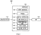
- FIG. 2 is a block diagram illustrating an example of a configuration of a manufacturing apparatus 100 according to the example embodiment, in which a solid arrow denotes a flow of data.
- the manufacturing apparatus 100 may include an imaging device 110, an arm 120, and a controller 130.
- the imaging device 110 may perform imaging of one or more of the first workpiece Wa, the second workpiece Wb, the shim S, and the arm 120, and thereby generate image data.
- the imaging device 110 may be able to communicate with the controller 130 by wire or wirelessly, and transmit the generated image data to the controller 130.
- the manufacturing apparatus 100 may include the imaging device 110.
- the manufacturing apparatus 100 may include one or more of various sensors instead of or in addition to the imaging device 110 in an alternative example embodiment.
- the sensor may detect a factor of one or more of the first workpiece Wa, the second workpiece Wb, the shim S, and the arm 120.
- Non-limiting examples of the factor may include a position and a motion.
- the arm 120 may be a robot arm or a manipulator, and may be automatically controlled by the controller 130.
- the arm 120 may perform any of a first insertion process and a second insertion process on the first workpiece Wa and the second workpiece Wb in accordance with a control executed by the controller 130.
- the first insertion process and the second insertion process are described later in greater detail.
- the controller 130 may be a personal computer, for example.
- the controller 130 may include an input interface 140, a storage 150, and a central controller 160.
- the controller 130 is not limited to the personal computer.
- the controller 130 may be a dedicated device or any computable device in an alternative example embodiment.
- the input interface 140 may be one or more of devices including a mouse, a keyboard, and a touch sensor, for example.
- the input interface 140 may accept an operation performed by a user, and transmit, to the central controller 160, input information that represents a result of the operation performed by the user.
- the storage 150 may be any storage including a hard disk drive (HDD), for example.
- the storage 150 may contain the statistic data that is obtained as a result of measuring the clearance CL provided between the first workpiece Wa and the second workpiece Wb.
- the statistic data may be based on an accumulation of measurement results obtained from size measurements of the large number of clearances CL, which are performed in the past on the first workpiece Wa and the second workpiece Wb.
- the central controller 160 may be a microcomputer, and may control, in an overall fashion, the controller 130 as a whole.
- the microcomputer may have devices including a central processing unit (CPU), a read-only memory (ROM) in which pieces of information including a program are stored, and a random-access memory (RAM) that serves as a work area.
- CPU central processing unit
- ROM read-only memory
- RAM random-access memory
- the central controller 160 may execute the program to serve as an arm controller 162, a representative value deriving unit 164, a first tester 166, and a second tester 168.
- the central controller 160 may serve as one or more of a "representative value deriving unit", a "first tester”, and a "second tester”.
- the arm controller 162 may analyze the image data transmitted from the imaging device 110, and control the arm 120. For example, the arm controller 162 may cause the arm 120 to operate the shim S or a jig such as a gauge. The arm 120 may be able to operate or move the shim S or the jig while holding the same.
- the representative value deriving unit 164 derives the representative value, e.g., the median ⁇ , of the clearance CL from the statistic data stored in the storage 150.
- the representative value deriving unit 164 may determine whether the derived median ⁇ is less than the tolerance d of the clearance CL. When the median ⁇ is less than the tolerance d of the clearance CL, the representative value deriving unit 164 may transmit, to the first tester 166, a signal indicating that the median ⁇ is less than the tolerance d.
- the representative value deriving unit 164 may transmit, to the second tester 168, a signal indicating that the median ⁇ is greater than the tolerance d.
- One of the first tester 166 and the second tester 168 may perform its corresponding process when the median ⁇ is equal to the tolerance d of the clearance CL.
- the second tester 168 may perform its corresponding process when the median ⁇ is equal to the tolerance d of the clearance CL.
- the first tester 166 executes the first insertion process when the median ⁇ is less than the tolerance d of the clearance CL.
- the second tester 168 executes the second insertion process when the median ⁇ is greater than the tolerance d of the clearance CL.
- the first tester 166 and the second tester 168 each may specify the shim S or the jig to be used in the corresponding insertion process.
- the arm controller 162 may execute a specific control of the arm 120 in accordance with instructions received from the first tester 166 or the second tester 168. For example, the arm controller 162 may control a position, an attitude, or any other factor of the arm 120.
- FIG. 3 is a flowchart illustrating an example of a flow of a manufacturing process to be performed by the manufacturing apparatus 100.
- the process illustrated by way of example in FIG. 3 may be performed once before an initial process of fastening the first workpiece Wa and the second workpiece Wb is performed.
- the representative value deriving unit 164 derives, from the statistic data stored in the storage 150, the representative value, e.g., the median ⁇ , of the clearance CL provided between the first workpiece Wa and the second workpiece Wb.
- the representative value deriving unit 164 may determine whether the derived median ⁇ is less than the tolerance d of the clearance CL. The flow may proceed to step S204 when the median ⁇ is less than the tolerance d (step S202: YES). The flow may proceed to step S206 when the median ⁇ is not less, i.e., equal to or greater than the tolerance d (step S202: NO).
- the representative value deriving unit 164 may determine to execute the first insertion process S300, and notify the first tester 166 of the execution of the first insertion process S300 accordingly. A description on the first insertion process S300 is given later in greater detail.
- the representative value deriving unit 164 may determine to execute the second insertion process S400, and notify the second tester 168 of the execution of the second insertion process S400 accordingly.
- a description on the second insertion process S400 is given later in greater detail.
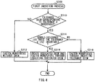
- FIG. 4 is a flowchart illustrating an example of a flow of a process performed in accordance with the first insertion process S300.
- the process illustrated by way of example in FIG. 4 may be performed when the representative value deriving unit 164 determines to execute the first insertion process S300 and before the process of fastening the first workpiece Wa and the second workpiece Wb is performed.
- the first tester 166 determines whether a tolerance shim is insertable into the clearance CL.
- tolerance shim refers to the shim S having a thickness corresponding to the tolerance d.
- the flow may proceed to step S312 when it is difficult or not possible to insert the tolerance shim into the clearance CL (step S310: NO).
- the flow may proceed to step S314 when the tolerance shim is insertable into the clearance CL (step S310: YES).
- the arm controller 162 may verify whether the tolerance shim is insertable in the determination performed at step S310. For example, in such verification, the arm controller 162 may cause the arm 120 to actually operate the tolerance shim. Note that any known method may be used to perform processes of the arm controller 162 and the arm 120 upon a process of determining the length of the clearance CL by means of the shim S or the jig, and therefore a description on such processes of the arm controller 162 and the arm 120 will not be provided in detail in the following.
- the first tester 166 may determine, at step S312, to fasten the first workpiece Wa and the second workpiece Wb without inserting the shim S into the clearance CL.
- the arm controller 162 may control the arm 120 to fasten the first workpiece Wa and the second workpiece Wb in accordance with the determination on the shim S to be used, or in accordance with the determination as to the execution of the fastening without using the shim S.
- any known method may be used to fasten the first workpiece Wa and the second workpiece Wb, and therefore a description on the fastening of the first workpiece Wa and the second workpiece Wb will not be provided in detail in the following.
- the first tester 166 determines, at step S314, whether a double-tolerance jig is insertable into the clearance CL.
- double-tolerance jig refers to a jig, such as a gauge, having a thickness twice the tolerance d (i.e., 2d).
- the flow may proceed to step S316 when the double-tolerance jig is insertable into the clearance CL (step S314: YES).
- the flow may proceed to step S318 when it is difficult or not possible to insert the double-tolerance jig into the clearance CL (step S314: NO).
- the first tester 166 may determine, at step S316, to create the dedicated shim S that matches with a size of the clearance CL and to fasten the first workpiece Wa and the second workpiece Wb through inserting the dedicated shim S into the clearance CL.
- the dedicated shim S that matches with the size of the clearance CL is referred to as a "dedicated shim”.
- the first tester 166 may determine, at step S318, to fasten the first workpiece Wa and the second workpiece Wb through inserting the tolerance shim into the clearance CL.
- FIG. 5 illustrates an example of a relationship between the clearances CL and the shims S according to the first insertion process S300, in which a vertical axis and a horizontal axis each illustrate a length of the clearance CL. Note that numerical values of respective scale marks illustrated in FIG. 5 are illustrative and non-limiting.
- the use of the shim S may be unnecessary when the clearance CL is equal to or less than the tolerance d.
- the tolerance shim may be used in an example case where the clearance CL is equal to or greater than the tolerance d and equal to or less than 2d, i.e., equal to or less than a value twice the tolerance d. In this case, the tolerance shim may fill the clearance CL, allowing a difference between the clearance CL and the tolerance shim to be equal to or less than the tolerance d.
- the dedicated shim that matches with a size of the clearance CL may be used in an example case where the clearance CL is greater than 2d, i.e., greater than the value twice the tolerance d. In this case, the dedicated shim may fill the clearance CL, allowing a difference between the clearance CL and the dedicated shim to be equal to or less than the tolerance d.
- the expression " ⁇ + ⁇ ⁇ d + ⁇ ⁇ 2d" holds true, meaning that the 1 ⁇ interval as well as any other interval are covered solely by the tolerance shim.
- simply preparing one kind of tolerance shim makes it possible to manufacture 68.27 % or more of the entire products. Similarly, it is possible to manufacture 95.55 % or more of the entire products when 2 ⁇ ⁇ d holds true, and to manufacture 99.73 % or more of the entire products when 3 ⁇ ⁇ d holds true.
- FIG. 6 is a flowchart illustrating an example of a flow of a process performed in accordance with the second insertion process S400.
- the process illustrated by way of example in FIG. 6 may be performed when the representative value deriving unit 164 determines to execute the second insertion process S400 and before the process of fastening the first workpiece Wa and the second workpiece Wb is performed.
- the second tester 168 determines whether a difference shim is insertable into the clearance CL.
- difference shim refers to the shim S having a thickness corresponding to a resultant of subtraction of the tolerance d from the median ⁇ .
- the flow may proceed to step S412 when it is difficult or not possible to insert the difference shim into the clearance CL (step S410: NO).
- the flow may proceed to step S418 when the difference shim is insertable into the clearance CL (step S410: YES).
- the second tester 168 may determine, at step S412, whether a tolerance jig is insertable into the clearance CL.
- a tolerance jig refers to a jig, such as a gauge, having a thickness corresponding to the tolerance d.
- the flow may proceed to step S414 when it is difficult or not possible to insert the tolerance jig into the clearance CL (step S412: NO).
- the flow may proceed to step S416 when the tolerance jig is insertable into the clearance CL (step S412: YES).
- the second tester 168 may determine, at step S414, to fasten the first workpiece Wa and the second workpiece Wb without inserting the shim S into the clearance CL.
- the second tester 168 may determine, at step S416, to create the dedicated shim S that matches with a size of the clearance CL and to fasten the first workpiece Wa and the second workpiece Wb through inserting the dedicated shim S into the clearance CL.
- the second tester 168 determines, at step S418, whether a representative shim is insertable into the clearance CL.
- representative shim refers to the shim S having a thickness corresponding to the median ⁇ .
- the flow may proceed to step S420 when it is difficult or not possible to insert the representative shim into the clearance CL (step S418: NO).
- the flow may proceed to step S422 when the representative shim is insertable into the clearance CL (step S418: YES).
- the second tester 168 may determine, at step S420, to fasten the first workpiece Wa and the second workpiece Wb through inserting the difference shim into the clearance CL.
- step S422 determines, at step S422, whether an addition jig is insertable into the clearance CL.
- additional jig refers to a jig, such as a gauge, having a thickness corresponding to a resultant of addition of the tolerance d to the median ⁇ .
- the flow may proceed to step S424 when the addition jig is insertable into the clearance CL (step S422: YES).
- the flow may proceed to step S426 when it is difficult or not possible to insert the addition jig into the clearance CL (step S422: NO).
- the second tester 168 may determine, at step S424, to create the dedicated shim S that matches with a size of the clearance CL and to fasten the first workpiece Wa and the second workpiece Wb through inserting the dedicated shim S into the clearance CL.
- the second tester 168 may determine, at step S426, to fasten the first workpiece Wa and the second workpiece Wb through inserting the representative shim into the clearance CL.
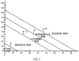
- FIG. 7 illustrates an example of a relationship between the clearances CL and the shims S according to the second insertion process S400, in which a vertical axis and a horizontal axis each illustrate a length of the clearance CL. Note that numerical values of respective scale marks illustrated in FIG. 7 are illustrative and non-limiting.
- the use of the shim S may be unnecessary when the clearance CL is equal to or less than the tolerance d.
- the dedicated shim that matches with a size of the clearance CL may be used in an example case where the clearance CL is equal to or greater than the tolerance d and equal to or less than the value in which the tolerance d is subtracted from the median ⁇ .
- the dedicated shim may fill the clearance CL, allowing a difference between the clearance CL and the dedicated shim to be equal to or less than the tolerance d.
- the difference shim may be used in an example case where the clearance CL is greater than the value in which the tolerance d is subtracted from the median ⁇ and equal to or less than the median ⁇ . In this case, the difference shim may fill the clearance CL, allowing a difference between the clearance CL and the difference shim to be equal to or less than the tolerance d.
- the representative shim may be used in an example case where the clearance CL is greater than the median ⁇ and equal to or less than the value in which the tolerance d is added to the median ⁇ . In this case, the representative shim may fill the clearance CL, allowing a difference between the clearance CL and the representative shim to be equal to or less than the tolerance d.
- the dedicated shim that matches with a size of the clearance CL may be used in an example case where the clearance CL is greater than the value in which the tolerance d is added to the median ⁇ . In this case, the dedicated shim may fill the clearance CL, allowing a difference between the clearance CL and the dedicated shim to be equal to or less than the tolerance d.
- the shim S becomes unnecessary at a rate of about half or more of the entire products upon manufacturing when the median ⁇ is less than the tolerance d ( ⁇ ⁇ d).
- the first insertion process S300 may be selected in which the preparation of only one kind of shim S, i.e., the tolerance shim suffices.
- the second insertion process S400 may be selected in which the two kinds of shims S having their respective thicknesses based on the median ⁇ as a reference.
- the first insertion process S300 and the second insertion process S400 are selected on a case-by-case basis through comparing the median ⁇ and the tolerance d. Hence, it is possible to keep the rate of fabricating the dedicated shim lower, and thereby to reduce operation man-hour.
- a design value of the thickness of the tolerance shim may be based on a tolerance that tolerates a size smaller than the tolerance d (referred to as a tolerance width x), where the tolerance d is an upper limit.
- a tolerance width x a tolerance that tolerates a size smaller than the tolerance d
- the tolerance d is an upper limit.
- a design value of the thickness of the double-tolerance jig may be based on a tolerance that tolerates a size smaller than a value 2d - x, where the value 2d - x is an upper limit.
- the value 2d - x may be a resultant of subtraction of the tolerance width x of the thickness of the tolerance shim from 2d that is the value twice the tolerance d.
- Such an alternative example embodiment ensures that the difference between the clearance CL and the double-tolerance jig is equal to or less than the tolerance d when the insertion of the double-tolerance jig is difficult or not possible.
- a tolerance may be set also for each of the various shims S and the jigs in the second insertion process S400 to ensure that the difference between the clearance CL and the shim (or the jig) is equal to or less than the tolerance d.
- the term "not insertable” and its variants not only means that the insertion of any shim or any jig described above into the clearance CL is not possible but also means that the insertion of any shim or any jig described above into the clearance CL is difficult.
- the central controller 160 illustrated in FIG. 2 is implementable by circuitry including at least one semiconductor integrated circuit such as at least one processor (e.g., a central processing unit (CPU)), at least one application specific integrated circuit (ASIC), and/or at least one field programmable gate array (FPGA).
- At least one processor is configurable, by reading instructions from at least one machine readable non-transitory tangible medium, to perform all or a part of functions of the central controller 160.
- Such a medium may take many forms, including, but not limited to, any type of magnetic medium such as a hard disk, any type of optical medium such as a CD and a DVD, any type of semiconductor memory (i.e., semiconductor circuit) such as a volatile memory and a non-volatile memory.
- any type of magnetic medium such as a hard disk
- any type of optical medium such as a CD and a DVD
- any type of semiconductor memory i.e., semiconductor circuit
- volatile memory i.e., volatile memory
- non-volatile memory any type of semiconductor memory (i.e., semiconductor circuit) such as a volatile memory and a non-volatile memory.
- the volatile memory may include a DRAM and a SRAM
- the nonvolatile memory may include a ROM and a NVRAM.
- the ASIC is an integrated circuit (IC) customized to perform
- the FPGA is an integrated circuit designed to be configured after manufacturing in order to perform, all or a part of the functions of the central controller 160 illustrated in FIG. 2 .
Landscapes
- Engineering & Computer Science (AREA)
- Manufacturing & Machinery (AREA)
- Physics & Mathematics (AREA)
- General Physics & Mathematics (AREA)
- General Engineering & Computer Science (AREA)
- Quality & Reliability (AREA)
- Automation & Control Theory (AREA)
- Transportation (AREA)
- Aviation & Aerospace Engineering (AREA)
- Mechanical Engineering (AREA)
- Automatic Assembly (AREA)
- Gasket Seals (AREA)
Abstract
Description
- The invention relates to a manufacturing method and a manufacturing apparatus that fasten workpieces that eventually structure an airframe of an aircraft.
- Manufacturing an aircraft involves operations including fastening a first workpiece and a second workpiece. The first workpiece and the second workpiece are fastened by a fastener that penetrates the first workpiece and the second workpiece. For example, reference is made to Japanese Patent No.
JP 5 931 458 B2 - An aspect of the invention provides a manufacturing method that includes:
- deriving, from statistic data, a representative value of a clearance that is provided between a first workpiece and a second workpiece, in which the first workpiece and the second workpiece eventually structure an airframe of an aircraft and are configured to be fastened to each other, and the statistic data is obtained from measuring the clearance;
- executing a first insertion process that includes testing insertion of a tolerance shim into the clearance when the representative value is less than a tolerance of the clearance, in which the tolerance shim has a thickness corresponding to the tolerance, and testing insertion of a double-tolerance jig into the clearance when the tolerance shim is insertable into the clearance in the testing the insertion of the tolerance shim, in which the double-tolerance jig has a thickness twice the tolerance; and executing a second insertion process that includes testing insertion of a difference shim into the clearance when the representative value is greater than the tolerance, in which the difference shim has a thickness corresponding to a resultant of subtraction of the tolerance from the representative value, testing insertion of a representative shim into the clearance when the difference shim is insertable into the clearance in the testing the insertion of the difference shim, in which the representative shim has a thickness corresponding to the representative value, and testing insertion of an addition jig into the clearance when the representative shim is insertable into the clearance in the testing the insertion of the representative shim, in which the addition jig has a thickness corresponding to a resultant of addition of the tolerance to the representative value.
- Another aspect of the invention provides a manufacturing apparatus that comprises:
- a representative value deriving unit configured to derive, from statistic data, a representative value of a clearance that is provided between a first workpiece and a second workpiece, in which the first workpiece and the second workpiece eventually structure an airframe of an aircraft and are configured to be fastened to each other, and the statistic data is obtained from measuring the clearance;
- a first tester configured to test insertion of a tolerance shim into the clearance when the representative value derived by the representative value deriving unit is less than a tolerance of the clearance, and test insertion of a double-tolerance jig into the clearance when the tolerance shim is insertable into the clearance, in which the tolerance shim has a thickness corresponding to the tolerance, and the double-tolerance jig has a thickness twice the tolerance; and
- a second tester configured to test insertion of a difference shim into the clearance when the representative value is greater than the tolerance, test insertion of a representative shim into the clearance when the difference shim is insertable into the clearance in the testing of the insertion of the difference shim, and test insertion of an addition jig into the clearance when the representative shim is insertable into the clearance in the testing of the insertion of the representative shim, in which the difference shim has a thickness corresponding to a resultant of subtraction of the tolerance from the representative value, the representative shim has a thickness corresponding to the representative value, and the addition jig has a thickness corresponding to a resultant of addition of the tolerance to the representative value.
-
- FIG. 1A
- is a cross-sectional view of a first workpiece, a second workpiece, and a shim during an operation process performed on the first workpiece and the second workpiece in a manufacturing method according to one implementation of the invention.
- FIG. 1B
- is a graph illustrating an example of statistic data obtained as a result of measuring a length of a clearance between the first workpiece and the second workpiece illustrated in
FIG. 1A . - FIG. 2
- is a block diagram illustrating an example of a configuration of a manufacturing apparatus according to one implementation of the invention.
- FIG. 3
- is a flowchart illustrating an example of a flow of a manufacturing process to be performed by the manufacturing apparatus illustrated in
FIG. 2 . - FIG. 4
- is a flowchart illustrating an example of a flow of a process performed in accordance with a first insertion process.
- FIG. 5
- is a diagram illustrating an example of a relationship between the clearances and the shims according to the first insertion process.
- FIG. 6
- is a flowchart illustrating an example of a flow of a process performed in accordance with a second insertion process.
- FIG. 7
- is a diagram illustrating an example of a relationship between the clearances and the shims according to the second insertion process.
- In the following, some embodiments of the invention are described in detail with reference to the accompanying drawings. Note that sizes, materials, specific values, and any other factors illustrated in respective embodiments are illustrative for easier understanding of the invention, and are not intended to limit the scope of the invention unless otherwise specifically stated. Further, elements in the following example embodiments which are not recited in a most-generic independent claim of the disclosure are optional and may be provided on an as-needed basis.
- The drawings are schematic and are not intended to be drawn to scale. Throughout the present specification and the drawings, elements having substantially the same function and configuration are denoted with the same reference numerals to avoid any redundant description. Further, elements that are not directly related to the invention are unillustrated in the drawings.
-
FIGS. 1A and 1B each illustrate an operation process performed on a first workpiece Wa and a second workpiece Wb in a manufacturing method according to an example embodiment of the invention, in whichFIG. 1A is a cross-sectional view of the first workpiece Wa, the second workpiece Wb, and a shim S.FIG. 1B illustrates an example of statistic data obtained as a result of measuring a length of a clearance CL provided between the first workpiece Wa and the second workpiece Wb illustrated inFIG. 1A . - The first workpiece Wa and the second workpiece Wb eventually structure an airframe of an aircraft. The first workpiece Wa and the second workpiece Wb each may serve as a work object. The first workpiece Wa and the second workpiece Wb may be pressed by an unillustrated fastener in directions in which the first and the second workpieces Wa and Wb are brought close to each other (denoted by arrows AR in
FIG. 1A ) and thus fastened by the fastener. The fastener can be a bolt or any other fastening member. - Referring to
FIG. 1A , when the first workpiece Wa and the second workpiece Wb are attached together, the clearance CL may possibly be formed between the first and the second workpieces Wa and Wb. Under such circumstances, tightening the first workpiece Wa and the second workpiece Wb by means of the fastener can eliminate the clearance CL. - On the other hand, this may possibly result in deformation of the first workpiece Wa, the second workpiece Wb, or both, raising a concern of internal stress generated in the first workpiece Wa and the second workpiece Wb, especially in the field of aircrafts. Accordingly, a tolerance "d" set for the clearance CL between the first workpiece Wa and the second workpiece Wb may sometimes be small in the field of aircrafts.
- In other words, a ratio in magnitude of the tolerance d to a dimension tolerance of the first workpiece Wa, the second workpiece Wb, or both may possibly be smaller than that in any field other than the field of aircrafts. Hence, a dimensional error in the first workpiece Wa, the second workpiece Wb, or both may often cause the clearance CL to fall outside the tolerance d.
- To suppress the internal stress of the first workpiece Wa and the second workpiece Wb, one measure may be to insert the shim S between the first workpiece Wa and the second workpiece Wb. In this case, the fastener may so fasten the first workpiece Wa and the second workpiece Wb as to penetrate the first workpiece Wa, the shim S, and the second workpiece Wb, for example. Unfortunately, forming the shim S for the clearance CL provided between the first workpiece Wa and the second workpiece Wb on an individual basis leads to an increase in operation man-hour.
- It is desirable to provide a manufacturing method and a manufacturing apparatus that are able to reduce operation man-hour.
- The example embodiment uses the statistic data on the clearance CL illustrated by way of example in
FIG. 1B . A graph illustrated inFIG. 1B may contain scale marks in a horizontal axis, in which the scale marks other than the scale mark corresponding to a median µ denote their respective relative values that are centered at the median µ. The statistic data on the clearance CL illustrated inFIG. 1B may be based on an assumption that the clearances CL vary in accordance with a normal distribution. - For example, roughly 68.27 % of the clearances CL may fall within a 1σ interval (an interval from -1σ to 1σ) relative to the median µ, roughly 95.55 % of the clearances CL may fall within a 2σ interval (an interval from -2σ to 2σ) relative to the median µ, and roughly 99.73 % of the clearances CL may fall within a 3σ interval (an interval from -3σ to 3σ) relative to the median µ.
- The median µ may be, for example, a representative value. Note that the example embodiment illustrated in
FIG. 1B uses the median µ as the representative value; however, the representative value of the clearances CL may be a mean value in an alternative example embodiment. -
FIG. 2 is a block diagram illustrating an example of a configuration of amanufacturing apparatus 100 according to the example embodiment, in which a solid arrow denotes a flow of data. Themanufacturing apparatus 100 may include animaging device 110, anarm 120, and acontroller 130. - The
imaging device 110 may perform imaging of one or more of the first workpiece Wa, the second workpiece Wb, the shim S, and thearm 120, and thereby generate image data. Theimaging device 110 may be able to communicate with thecontroller 130 by wire or wirelessly, and transmit the generated image data to thecontroller 130. Note that themanufacturing apparatus 100 according to the example embodiment may include theimaging device 110. - However, the
manufacturing apparatus 100 may include one or more of various sensors instead of or in addition to theimaging device 110 in an alternative example embodiment. The sensor may detect a factor of one or more of the first workpiece Wa, the second workpiece Wb, the shim S, and thearm 120. Non-limiting examples of the factor may include a position and a motion. - The
arm 120 may be a robot arm or a manipulator, and may be automatically controlled by thecontroller 130. Thearm 120 may perform any of a first insertion process and a second insertion process on the first workpiece Wa and the second workpiece Wb in accordance with a control executed by thecontroller 130. The first insertion process and the second insertion process are described later in greater detail. - The
controller 130 may be a personal computer, for example. Thecontroller 130 may include aninput interface 140, astorage 150, and acentral controller 160. Note that thecontroller 130 is not limited to the personal computer. For example, thecontroller 130 may be a dedicated device or any computable device in an alternative example embodiment. - The
input interface 140 may be one or more of devices including a mouse, a keyboard, and a touch sensor, for example. Theinput interface 140 may accept an operation performed by a user, and transmit, to thecentral controller 160, input information that represents a result of the operation performed by the user. - The
storage 150 may be any storage including a hard disk drive (HDD), for example. Thestorage 150 may contain the statistic data that is obtained as a result of measuring the clearance CL provided between the first workpiece Wa and the second workpiece Wb. The statistic data may be based on an accumulation of measurement results obtained from size measurements of the large number of clearances CL, which are performed in the past on the first workpiece Wa and the second workpiece Wb. - The
central controller 160 may be a microcomputer, and may control, in an overall fashion, thecontroller 130 as a whole. The microcomputer may have devices including a central processing unit (CPU), a read-only memory (ROM) in which pieces of information including a program are stored, and a random-access memory (RAM) that serves as a work area. - The
central controller 160 may execute the program to serve as anarm controller 162, a representativevalue deriving unit 164, afirst tester 166, and asecond tester 168. In one embodiment, thecentral controller 160 may serve as one or more of a "representative value deriving unit", a "first tester", and a "second tester". - The
arm controller 162 may analyze the image data transmitted from theimaging device 110, and control thearm 120. For example, thearm controller 162 may cause thearm 120 to operate the shim S or a jig such as a gauge. Thearm 120 may be able to operate or move the shim S or the jig while holding the same. - The representative
value deriving unit 164 derives the representative value, e.g., the median µ, of the clearance CL from the statistic data stored in thestorage 150. The representativevalue deriving unit 164 may determine whether the derived median µ is less than the tolerance d of the clearance CL. When the median µ is less than the tolerance d of the clearance CL, the representativevalue deriving unit 164 may transmit, to thefirst tester 166, a signal indicating that the median µ is less than the tolerance d. - When the median µ is greater than the tolerance d of the clearance CL, the representative
value deriving unit 164 may transmit, to thesecond tester 168, a signal indicating that the median µ is greater than the tolerance d. One of thefirst tester 166 and thesecond tester 168 may perform its corresponding process when the median µ is equal to the tolerance d of the clearance CL. In the example embodiment, without limitation, thesecond tester 168 may perform its corresponding process when the median µ is equal to the tolerance d of the clearance CL. - The
first tester 166 executes the first insertion process when the median µ is less than the tolerance d of the clearance CL. Thesecond tester 168 executes the second insertion process when the median µ is greater than the tolerance d of the clearance CL. Upon executing corresponding one of the first insertion process and the second insertion process, thefirst tester 166 and thesecond tester 168 each may specify the shim S or the jig to be used in the corresponding insertion process. - The
arm controller 162 may execute a specific control of thearm 120 in accordance with instructions received from thefirst tester 166 or thesecond tester 168. For example, thearm controller 162 may control a position, an attitude, or any other factor of thearm 120. - In the following, with reference to flowcharts, a description is given of selection of the first and the second insertion processes and specific but non-limiting flows of the first and the second insertion processes.
-
FIG. 3 is a flowchart illustrating an example of a flow of a manufacturing process to be performed by themanufacturing apparatus 100. For example, the process illustrated by way of example inFIG. 3 may be performed once before an initial process of fastening the first workpiece Wa and the second workpiece Wb is performed. - At step S200, the representative
value deriving unit 164 derives, from the statistic data stored in thestorage 150, the representative value, e.g., the median µ, of the clearance CL provided between the first workpiece Wa and the second workpiece Wb. - At step S202, the representative
value deriving unit 164 may determine whether the derived median µ is less than the tolerance d of the clearance CL. The flow may proceed to step S204 when the median µ is less than the tolerance d (step S202: YES). The flow may proceed to step S206 when the median µ is not less, i.e., equal to or greater than the tolerance d (step S202: NO). - When the median µ is less than the tolerance d (step S202: YES), at step S204, the representative
value deriving unit 164 may determine to execute the first insertion process S300, and notify thefirst tester 166 of the execution of the first insertion process S300 accordingly. A description on the first insertion process S300 is given later in greater detail. - When the median µ is not less, i.e., equal to or greater than the tolerance d (step S202: NO), at step S206, the representative
value deriving unit 164 may determine to execute the second insertion process S400, and notify thesecond tester 168 of the execution of the second insertion process S400 accordingly. A description on the second insertion process S400 is given later in greater detail. -
FIG. 4 is a flowchart illustrating an example of a flow of a process performed in accordance with the first insertion process S300. For example, the process illustrated by way of example inFIG. 4 may be performed when the representativevalue deriving unit 164 determines to execute the first insertion process S300 and before the process of fastening the first workpiece Wa and the second workpiece Wb is performed. - At step S310, the
first tester 166 determines whether a tolerance shim is insertable into the clearance CL. As used herein, the term "tolerance shim" refers to the shim S having a thickness corresponding to the tolerance d. The flow may proceed to step S312 when it is difficult or not possible to insert the tolerance shim into the clearance CL (step S310: NO). The flow may proceed to step S314 when the tolerance shim is insertable into the clearance CL (step S310: YES). - In the example embodiment, the
arm controller 162 may verify whether the tolerance shim is insertable in the determination performed at step S310. For example, in such verification, thearm controller 162 may cause thearm 120 to actually operate the tolerance shim. Note that any known method may be used to perform processes of thearm controller 162 and thearm 120 upon a process of determining the length of the clearance CL by means of the shim S or the jig, and therefore a description on such processes of thearm controller 162 and thearm 120 will not be provided in detail in the following. - When it is difficult or not possible to insert the tolerance shim into the clearance CL at step S310 (step S310: NO), the
first tester 166 may determine, at step S312, to fasten the first workpiece Wa and the second workpiece Wb without inserting the shim S into the clearance CL. - Note that the
arm controller 162 may control thearm 120 to fasten the first workpiece Wa and the second workpiece Wb in accordance with the determination on the shim S to be used, or in accordance with the determination as to the execution of the fastening without using the shim S. Here, any known method may be used to fasten the first workpiece Wa and the second workpiece Wb, and therefore a description on the fastening of the first workpiece Wa and the second workpiece Wb will not be provided in detail in the following. - When the tolerance shim is insertable into the clearance CL at step S310 (step S310: YES), the
first tester 166 determines, at step S314, whether a double-tolerance jig is insertable into the clearance CL. As used herein, the term "double-tolerance jig" refers to a jig, such as a gauge, having a thickness twice the tolerance d (i.e., 2d). The flow may proceed to step S316 when the double-tolerance jig is insertable into the clearance CL (step S314: YES). The flow may proceed to step S318 when it is difficult or not possible to insert the double-tolerance jig into the clearance CL (step S314: NO). - When the double-tolerance jig is insertable into the clearance CL at step S314 (step S314: YES), the
first tester 166 may determine, at step S316, to create the dedicated shim S that matches with a size of the clearance CL and to fasten the first workpiece Wa and the second workpiece Wb through inserting the dedicated shim S into the clearance CL. Hereinafter, the dedicated shim S that matches with the size of the clearance CL is referred to as a "dedicated shim". - When it is difficult or not possible to insert the double-tolerance jig into the clearance CL at step S314 (step S314: NO), the
first tester 166 may determine, at step S318, to fasten the first workpiece Wa and the second workpiece Wb through inserting the tolerance shim into the clearance CL. -
FIG. 5 illustrates an example of a relationship between the clearances CL and the shims S according to the first insertion process S300, in which a vertical axis and a horizontal axis each illustrate a length of the clearance CL. Note that numerical values of respective scale marks illustrated inFIG. 5 are illustrative and non-limiting. - Referring to
FIG. 5 , the use of the shim S may be unnecessary when the clearance CL is equal to or less than the tolerance d. In addition, the tolerance shim may be used in an example case where the clearance CL is equal to or greater than the tolerance d and equal to or less than 2d, i.e., equal to or less than a value twice the tolerance d. In this case, the tolerance shim may fill the clearance CL, allowing a difference between the clearance CL and the tolerance shim to be equal to or less than the tolerance d. Further, the dedicated shim that matches with a size of the clearance CL may be used in an example case where the clearance CL is greater than 2d, i.e., greater than the value twice the tolerance d. In this case, the dedicated shim may fill the clearance CL, allowing a difference between the clearance CL and the dedicated shim to be equal to or less than the tolerance d. - Assuming that the clearance CL is designed to be equal to or greater than 0 (zero), and that the variation σ of the clearance CL is less than the tolerance d (σ < d) in the statistics data when the variation σ of the clearance CL and the tolerance d of the clearance CL are compared with each other, the expression "µ + σ < d + σ < 2d" holds true, meaning that the 1σ interval as well as any other interval are covered solely by the tolerance shim. In other words, simply preparing one kind of tolerance shim makes it possible to manufacture 68.27 % or more of the entire products. Similarly, it is possible to manufacture 95.55 % or more of the entire products when 2σ < d holds true, and to manufacture 99.73 % or more of the entire products when 3σ < d holds true.
-
FIG. 6 is a flowchart illustrating an example of a flow of a process performed in accordance with the second insertion process S400. For example, the process illustrated by way of example inFIG. 6 may be performed when the representativevalue deriving unit 164 determines to execute the second insertion process S400 and before the process of fastening the first workpiece Wa and the second workpiece Wb is performed. - At step S410, the
second tester 168 determines whether a difference shim is insertable into the clearance CL. As used herein, the term "difference shim" refers to the shim S having a thickness corresponding to a resultant of subtraction of the tolerance d from the median µ. The flow may proceed to step S412 when it is difficult or not possible to insert the difference shim into the clearance CL (step S410: NO). The flow may proceed to step S418 when the difference shim is insertable into the clearance CL (step S410: YES). - When it is difficult or not possible to insert the difference shim into the clearance CL at step S410 (step S410: NO), the
second tester 168 may determine, at step S412, whether a tolerance jig is insertable into the clearance CL. As used herein, the term "tolerance jig" refers to a jig, such as a gauge, having a thickness corresponding to the tolerance d. The flow may proceed to step S414 when it is difficult or not possible to insert the tolerance jig into the clearance CL (step S412: NO). The flow may proceed to step S416 when the tolerance jig is insertable into the clearance CL (step S412: YES). - When it is difficult or not possible to insert the tolerance jig into the clearance CL at step S412 (step S412: NO), the
second tester 168 may determine, at step S414, to fasten the first workpiece Wa and the second workpiece Wb without inserting the shim S into the clearance CL. - When the tolerance jig is insertable into the clearance CL at step S412 (step S412: YES), the
second tester 168 may determine, at step S416, to create the dedicated shim S that matches with a size of the clearance CL and to fasten the first workpiece Wa and the second workpiece Wb through inserting the dedicated shim S into the clearance CL. - When the difference shim is insertable into the clearance CL at step S410 (step S410: YES), the
second tester 168 determines, at step S418, whether a representative shim is insertable into the clearance CL. As used herein, the term "representative shim" refers to the shim S having a thickness corresponding to the median µ. The flow may proceed to step S420 when it is difficult or not possible to insert the representative shim into the clearance CL (step S418: NO). The flow may proceed to step S422 when the representative shim is insertable into the clearance CL (step S418: YES). - When it is difficult or not possible to insert the representative shim into the clearance CL at step S418 (step S418: NO), the
second tester 168 may determine, at step S420, to fasten the first workpiece Wa and the second workpiece Wb through inserting the difference shim into the clearance CL. - When the representative shim is insertable into the clearance CL (step S418: YES), the
second tester 168 determines, at step S422, whether an addition jig is insertable into the clearance CL. As used herein, the term "addition jig" refers to a jig, such as a gauge, having a thickness corresponding to a resultant of addition of the tolerance d to the median µ. The flow may proceed to step S424 when the addition jig is insertable into the clearance CL (step S422: YES). The flow may proceed to step S426 when it is difficult or not possible to insert the addition jig into the clearance CL (step S422: NO). - When the addition jig is insertable into the clearance CL at step S422 (step S422: YES), the
second tester 168 may determine, at step S424, to create the dedicated shim S that matches with a size of the clearance CL and to fasten the first workpiece Wa and the second workpiece Wb through inserting the dedicated shim S into the clearance CL. - When it is difficult or not possible to insert the addition jig into the clearance CL at step S422 (step S422: NO), the
second tester 168 may determine, at step S426, to fasten the first workpiece Wa and the second workpiece Wb through inserting the representative shim into the clearance CL. -
FIG. 7 illustrates an example of a relationship between the clearances CL and the shims S according to the second insertion process S400, in which a vertical axis and a horizontal axis each illustrate a length of the clearance CL. Note that numerical values of respective scale marks illustrated inFIG. 7 are illustrative and non-limiting. - Referring to
FIG. 7 , the use of the shim S may be unnecessary when the clearance CL is equal to or less than the tolerance d. In addition, the dedicated shim that matches with a size of the clearance CL may be used in an example case where the clearance CL is equal to or greater than the tolerance d and equal to or less than the value in which the tolerance d is subtracted from the median µ. In this case, the dedicated shim may fill the clearance CL, allowing a difference between the clearance CL and the dedicated shim to be equal to or less than the tolerance d. - Further, the difference shim may be used in an example case where the clearance CL is greater than the value in which the tolerance d is subtracted from the median µ and equal to or less than the median µ. In this case, the difference shim may fill the clearance CL, allowing a difference between the clearance CL and the difference shim to be equal to or less than the tolerance d.
- Further, the representative shim may be used in an example case where the clearance CL is greater than the median µ and equal to or less than the value in which the tolerance d is added to the median µ. In this case, the representative shim may fill the clearance CL, allowing a difference between the clearance CL and the representative shim to be equal to or less than the tolerance d.
- Further, the dedicated shim that matches with a size of the clearance CL may be used in an example case where the clearance CL is greater than the value in which the tolerance d is added to the median µ. In this case, the dedicated shim may fill the clearance CL, allowing a difference between the clearance CL and the dedicated shim to be equal to or less than the tolerance d.
- Assuming that the variation σ of the clearance CL is less than the tolerance d (σ < d) in the statistics data when the variation σ of the clearance CL and the tolerance d of the clearance CL are compared with each other, the expression
"µ - d < µ - σ < µ < µ + σ < µ + d" holds true, meaning that the 1σ interval as well as any other interval are covered by the difference shim and the representative shim. In other words, simply preparing two kinds of shims S makes it possible to manufacture 68.27 % or more of the entire products. Similarly, it is possible to manufacture 95.55 % or more of the entire products when 2σ < d holds true, and to manufacture 99.73 % or more of the entire products when 3σ <d holds true. - According to the foregoing example embodiment, it is possible to keep a rate of fabricating the dedicated shim low owing to the first insertion process S300 and the second insertion process S400, and thereby to reduce operation man-hour.
- Further, the shim S becomes unnecessary at a rate of about half or more of the entire products upon manufacturing when the median µ is less than the tolerance d (µ < d). Hence, in this case, the first insertion process S300 may be selected in which the preparation of only one kind of shim S, i.e., the tolerance shim suffices. When the median µ is greater than the tolerance d (µ > d), sometimes the tolerance d may possibly be extremely large with respect to the median µ. Hence, in this case, the second insertion process S400 may be selected in which the two kinds of shims S having their respective thicknesses based on the median µ as a reference.
- Accordingly, the first insertion process S300 and the second insertion process S400 are selected on a case-by-case basis through comparing the median µ and the tolerance d. Hence, it is possible to keep the rate of fabricating the dedicated shim lower, and thereby to reduce operation man-hour.
- Although some preferred embodiments of the invention have been described in the foregoing by way of example with reference to the accompanying drawings, the invention is by no means limited to the embodiments described above. It should be appreciated that modifications and alterations may be made by persons skilled in the art without departing from the scope as defined by the appended claims. The invention is intended to include such modifications and alterations in so far as they fall within the scope of the appended claims or the equivalents thereof.
- For example, in the first insertion process S300 according to the foregoing example embodiment, a design value of the thickness of the tolerance shim may be based on a tolerance that tolerates a size smaller than the tolerance d (referred to as a tolerance width x), where the tolerance d is an upper limit. Such an alternative embodiment ensures that the difference between the clearance CL and the tolerance shim is equal to or less than the tolerance d when the insertion of the tolerance shim is difficult or not possible.
- Further, in the first insertion process S300 according to the foregoing example embodiment, a design value of the thickness of the double-tolerance jig may be based on a tolerance that tolerates a size smaller than a
value 2d - x, where thevalue 2d - x is an upper limit. Thevalue 2d - x may be a resultant of subtraction of the tolerance width x of the thickness of the tolerance shim from 2d that is the value twice the tolerance d. Such an alternative example embodiment ensures that the difference between the clearance CL and the double-tolerance jig is equal to or less than the tolerance d when the insertion of the double-tolerance jig is difficult or not possible. - The foregoing example embodiment has been described by referring to the tolerance of each of the shim S and the jig in the first insertion process S300. In an alternative example embodiment, a tolerance may be set also for each of the various shims S and the jigs in the second insertion process S400 to ensure that the difference between the clearance CL and the shim (or the jig) is equal to or less than the tolerance d.
- As used herein, the term "not insertable" and its variants not only means that the insertion of any shim or any jig described above into the clearance CL is not possible but also means that the insertion of any shim or any jig described above into the clearance CL is difficult.
- The
central controller 160 illustrated inFIG. 2 is implementable by circuitry including at least one semiconductor integrated circuit such as at least one processor (e.g., a central processing unit (CPU)), at least one application specific integrated circuit (ASIC), and/or at least one field programmable gate array (FPGA). At least one processor is configurable, by reading instructions from at least one machine readable non-transitory tangible medium, to perform all or a part of functions of thecentral controller 160. - Such a medium may take many forms, including, but not limited to, any type of magnetic medium such as a hard disk, any type of optical medium such as a CD and a DVD, any type of semiconductor memory (i.e., semiconductor circuit) such as a volatile memory and a non-volatile memory.
- The volatile memory may include a DRAM and a SRAM, and the nonvolatile memory may include a ROM and a NVRAM. The ASIC is an integrated circuit (IC) customized to perform, and the FPGA is an integrated circuit designed to be configured after manufacturing in order to perform, all or a part of the functions of the
central controller 160 illustrated inFIG. 2 . -
- Wa
- first workpiece
- Wb
- second workpiece
- CL
- clearance
- d
- tolerance
- µ
- median
- x
- tolerance width
- AR
- arrow
- S
- shim
- 100
- manufacturing apparatus
- 110
- imaging device
- 120
- arm
- 130
- controller
- 140
- input interface
- 150
- storage
- 160
- central controller
- 162
- arm controller
- 164
- representative value deriving unit
- 166
- first tester
- 168
- second tester
Claims (8)
- A manufacturing method comprising:- deriving, from statistic data, a representative value of a clearance that is provided between a first workpiece (Wa) and a second workpiece (Wb), the first workpiece (Wa) and the second workpiece (Wb) eventually structuring an airframe of an aircraft and being configured to be fastened to each other, the statistic data being obtained from measuring the clearance;- executing a first insertion process (S300) that includes testing insertion of a tolerance shim (S) into the clearance (CL) when the representative value is less than a tolerance of the clearance (CL), the tolerance shim (S) having a thickness corresponding to the tolerance, and- testing insertion of a double-tolerance jig into the clearance (CL) when the tolerance shim (S) is insertable into the clearance (CL) in the testing the insertion of the tolerance shim (S), the double-tolerance jig having a thickness twice the tolerance; and- executing a second insertion process (S400) that includes- testing insertion of a difference shim into the clearance (CL) when the representative value (µ) is greater than the tolerance (d), the difference shim having a thickness corresponding to a resultant of subtraction (µ - d) of the tolerance (d) from the representative value (µ),- testing insertion of a representative shim into the clearance (CL) when the difference shim is insertable into the clearance (CL) in the testing the insertion of the difference shim, the representative shim having a thickness corresponding to the representative value, and- testing insertion of an addition jig into the clearance (CL) when the representative shim is insertable into the clearance (CL) in the testing the insertion of the representative shim, the addition jig having a thickness corresponding to a resultant of addition of the tolerance to the representative value.
- The manufacturing method according to claim 1,
wherein the executing the first insertion process (S300) further comprises fastening the first workpiece (Wa) and the second workpiece (Wb) without any shim when the tolerance shim (S) is not insertable into the clearance (CL) in the testing the insertion of the tolerance shim (S). - The manufacturing method according to claim 1 or 2,
wherein the executing the first insertion process (S300) further comprises:- inserting the tolerance shim (S) into the clearance (CL) when the double-tolerance jig is not insertable into the clearance (CL) in the testing the insertion of the double-tolerance jig; and- fastening the first workpiece (Wa) and the second workpiece (Wb) with the tolerance shim (S) being inserted into the clearance (CL). - The manufacturing method according to any one of claims 1 to 3,
wherein the executing the second insertion process (S400) further comprises testing insertion of a tolerance jig into the clearance (CL) when the difference shim is not insertable into the clearance (CL) in the testing the insertion of the difference shim, the tolerance jig having a thickness corresponding to the tolerance. - The manufacturing method according to claim 4,
wherein the executing the second insertion process (S400) further comprises fastening the first workpiece (Wa) and the second workpiece (Wb) without any shim when the tolerance jig is not insertable into the clearance (CL) in the testing the insertion of the tolerance jig. - The manufacturing method according to any one of claims 1 to 5,
wherein the executing the second insertion process (S400) further comprises:- inserting the difference shim into the clearance (CL) when the representative shim is not insertable into the clearance (CL) in the testing the insertion of the representative shim; and- fastening the first workpiece (Wa) and the second workpiece (Wb) with the difference shim being inserted into the clearance (CL). - The manufacturing method according to any one of claims 1 to 6,
wherein the executing the second insertion process (S400) further comprises:- inserting the representative shim into the clearance (CL) when the addition jig is not insertable into the clearance (CL) in the testing the insertion of the addition jig; and- fastening the first workpiece (Wa) and the second workpiece (Wb) with the representative shim being inserted into the clearance (CL). - A manufacturing apparatus comprising:- a representative value deriving unit (164) configured to derive, from statistic data, a representative value of a clearance (CL) that is provided between a first workpiece (Wa) and a second workpiece (Wb), the first workpiece (Wa) and the second workpiece (Wb) eventually structuring an airframe of an aircraft and being configured to be fastened to each other, the statistic data being obtained from measuring the clearance (CL);- a first tester (166) configured to test insertion of a tolerance shim (S) into the clearance (CL) when the representative value derived by the representative value deriving unit (164) is less than a tolerance of the clearance (CL), and test insertion of a double-tolerance jig into the clearance (CL) when the tolerance shim (S) is insertable into the clearance (CL) in the testing of the insertion of the tolerance shim (S), the tolerance shim (S) having a thickness corresponding to the tolerance, the double-tolerance jig having a thickness twice the tolerance; and- a second tester (168) configured to test insertion of a difference shim into the clearance (CL) when the representative value is greater than the tolerance, test insertion of a representative shim (S) into the clearance (CL) when the difference shim is insertable into the clearance (CL) in the testing of the insertion of the difference shim, and test insertion of an addition jig into the clearance (CL) when the representative shim (S) is insertable into the clearance (CL) in the testing of the insertion of the representative shim (S), the difference shim having a thickness corresponding to a resultant of subtraction of the tolerance from the representative value, the representative shim having a thickness corresponding to the representative value, the addition jig having a thickness corresponding to a resultant of addition of the tolerance to the representative value.
Applications Claiming Priority (1)
| Application Number | Priority Date | Filing Date | Title |
|---|---|---|---|
| JP2017229674A JP6663414B2 (en) | 2017-11-29 | 2017-11-29 | Manufacturing method and manufacturing apparatus |
Publications (2)
| Publication Number | Publication Date |
|---|---|
| EP3493009A1 true EP3493009A1 (en) | 2019-06-05 |
| EP3493009B1 EP3493009B1 (en) | 2020-07-22 |
Family
ID=64100564
Family Applications (1)
| Application Number | Title | Priority Date | Filing Date |
|---|---|---|---|
| EP18202793.8A Active EP3493009B1 (en) | 2017-11-29 | 2018-10-26 | Manufacturing method and manufacturing apparatus |
Country Status (4)
| Country | Link |
|---|---|
| US (1) | US11117228B2 (en) |
| EP (1) | EP3493009B1 (en) |
| JP (1) | JP6663414B2 (en) |
| CN (1) | CN109834625B (en) |
Families Citing this family (4)
| Publication number | Priority date | Publication date | Assignee | Title |
|---|---|---|---|---|
| US11292614B2 (en) * | 2019-05-28 | 2022-04-05 | The Boeing Company | Method for producing an aircraft |
| CN111498083B (en) * | 2020-04-15 | 2021-08-03 | 成都飞机工业(集团)有限责任公司 | Laminar flow wing aircraft aerodynamic outer edge tolerance control method |
| JP7820126B2 (en) * | 2020-11-18 | 2026-02-25 | ザ・ボーイング・カンパニー | Assembly line manufacturing and aircraft wing assembly |
| CN112643307B (en) * | 2020-11-30 | 2022-10-04 | 北京星航机电装备有限公司 | Special-shaped cambered surface lap joint cover plate assembling tool and assembling method |
Citations (4)
| Publication number | Priority date | Publication date | Assignee | Title |
|---|---|---|---|---|
| JPS5931458B2 (en) | 1977-09-02 | 1984-08-02 | エヌオーケー株式会社 | sliding material |
| US20080205763A1 (en) * | 2007-02-28 | 2008-08-28 | The Boeing Company | Method for fitting part assemblies |
| US20080256788A1 (en) * | 2005-09-22 | 2008-10-23 | Airbus Uk Limited | Assembly of Aircraft Components |
| EP2533167A2 (en) * | 2011-06-08 | 2012-12-12 | The Boeing Company | Digitally designed shims for joining parts of an assembly |
Family Cites Families (11)
| Publication number | Priority date | Publication date | Assignee | Title |
|---|---|---|---|---|
| US5956251A (en) * | 1995-06-28 | 1999-09-21 | The Boeing Company | Statistical tolerancing |
| GB0901640D0 (en) * | 2009-02-03 | 2009-03-11 | Airbus Uk Ltd | Joint |
| ES2383424B1 (en) * | 2009-09-29 | 2013-05-03 | Airbus Operations S.L. | AIRCRAFT NOTEBOOK AND METHOD OF OBTAINING THE SAME |
| JP5931458B2 (en) | 2012-01-17 | 2016-06-08 | 三菱航空機株式会社 | How to install lightning-resistant fasteners and lightning-resistant fasteners |
| US9990446B2 (en) | 2014-04-15 | 2018-06-05 | The Boeing Company | Predictive shimming for flexible surfaces |
| US10275565B2 (en) * | 2015-11-06 | 2019-04-30 | The Boeing Company | Advanced automated process for the wing-to-body join of an aircraft with predictive surface scanning |
| US10450053B2 (en) * | 2016-05-11 | 2019-10-22 | The Boeing Company | Methods using predictive shimming to optimize part-to-part alignment |
| US10934020B2 (en) * | 2017-01-25 | 2021-03-02 | The Boeing Company | Method and system for joining structures |
| CN107380478A (en) * | 2017-07-27 | 2017-11-24 | 中航沈飞民用飞机有限责任公司 | A kind of method for optimizing technique for aircraft composite component assembly binding face gap |
| US10317886B1 (en) * | 2018-04-30 | 2019-06-11 | Shimtech Industries US, Inc. | Method and system for automated shim manufacturing |
| US11170495B2 (en) * | 2019-10-21 | 2021-11-09 | The Boeing Company | Scanning apparatus and method of scanning |
-
2017
- 2017-11-29 JP JP2017229674A patent/JP6663414B2/en active Active
-
2018
- 2018-10-02 US US16/149,288 patent/US11117228B2/en active Active
- 2018-10-08 CN CN201811167543.7A patent/CN109834625B/en active Active
- 2018-10-26 EP EP18202793.8A patent/EP3493009B1/en active Active
Patent Citations (4)
| Publication number | Priority date | Publication date | Assignee | Title |
|---|---|---|---|---|
| JPS5931458B2 (en) | 1977-09-02 | 1984-08-02 | エヌオーケー株式会社 | sliding material |
| US20080256788A1 (en) * | 2005-09-22 | 2008-10-23 | Airbus Uk Limited | Assembly of Aircraft Components |
| US20080205763A1 (en) * | 2007-02-28 | 2008-08-28 | The Boeing Company | Method for fitting part assemblies |
| EP2533167A2 (en) * | 2011-06-08 | 2012-12-12 | The Boeing Company | Digitally designed shims for joining parts of an assembly |
Non-Patent Citations (2)
| Title |
|---|
| EHMKE FABIAN ET AL: "Single step shimming solution for automated aircraft assembly", 2017 13TH IEEE CONFERENCE ON AUTOMATION SCIENCE AND ENGINEERING (CASE), IEEE, 20 August 2017 (2017-08-20), pages 662 - 667, XP033299320, DOI: 10.1109/COASE.2017.8256179 * |
| KRITHIKA MANOHAR ET AL: "Predicting shim gaps in aircraft assembly with machine learning and sparse sensing", ARXIV, 24 November 2017 (2017-11-24), pages 1 - 13, XP055579146, Retrieved from the Internet <URL:https://arxiv.org/pdf/1711.08861.pdf> [retrieved on 20190409], DOI: 10.1016/j.jmsy.2018.01.011 * |
Also Published As
| Publication number | Publication date |
|---|---|
| CN109834625B (en) | 2022-04-29 |
| EP3493009B1 (en) | 2020-07-22 |
| US11117228B2 (en) | 2021-09-14 |
| JP6663414B2 (en) | 2020-03-11 |
| JP2019098843A (en) | 2019-06-24 |
| US20190160607A1 (en) | 2019-05-30 |
| CN109834625A (en) | 2019-06-04 |
Similar Documents
| Publication | Publication Date | Title |
|---|---|---|
| EP3521958B1 (en) | Manufacturing assistance apparatus | |
| EP3493009B1 (en) | Manufacturing method and manufacturing apparatus | |
| CN112904797A (en) | Numerical controller and control method | |
| US9158867B2 (en) | 2D/3D analysis for abnormal tools and stages diagnosis | |
| Nitsche et al. | Measurement uncertainty evaluation of a hexapod-structured calibration device for multi-component force and moment sensors | |
| KR20190137131A (en) | Machine vision systems | |
| US12013259B2 (en) | Providing compensation parameters for sensor integrated circuits | |
| Barhak et al. | Integration of reconfigurable inspection with stream of variations methodology | |
| CN114425643A (en) | Method and device for automatically processing batch parts | |
| CN114491953A (en) | Method and device for automatically calibrating and detecting workpieces | |
| TW202105053A (en) | In-die metrology methods and systems for process control | |
| JP5116307B2 (en) | Integrated circuit device abnormality detection device, method and program | |
| US8321048B1 (en) | Associating data with workpieces and correlating the data with yield data | |
| JP2003232688A (en) | Two-dimensional stress field measurement system and two-dimensional stress field measurement program | |
| Granig et al. | Dependability considerations of redundant sensor systems | |
| TWI472939B (en) | Yield loss prediction method and associated computer readable medium | |
| Beckmann et al. | Tolerance simulation in the assembling process based on experimental data from series production | |
| CN109219871A (en) | Use the electric placed in connection of the metering target of design analysis | |
| Szipka | Modelling and Management of Uncertainty in Production Systems: From Measurement to Decision | |
| Kugunavar et al. | Uncertainty analysis of workpiece orientation: A mathematical decision support system for circular geometry measurements | |
| US20200240767A1 (en) | Coordinate measurement validation | |
| JP4720084B2 (en) | Method for obtaining shape data of measurement object, and method for aligning shape data and CAD data of measurement object using the same | |
| US20210263536A1 (en) | Internal-load calculation apparatus and method of calculating internal load | |
| WO2026078773A1 (en) | Parameter identification device, parameter identification method, and recording medium | |
| Majda et al. | Metrological constraints and uncertainty of tool deflection measurements in machine tools and articulated robots |
Legal Events
| Date | Code | Title | Description |
|---|---|---|---|
| PUAI | Public reference made under article 153(3) epc to a published international application that has entered the european phase |
Free format text: ORIGINAL CODE: 0009012 |
|
| STAA | Information on the status of an ep patent application or granted ep patent |
Free format text: STATUS: THE APPLICATION HAS BEEN PUBLISHED |
|
| AK | Designated contracting states |
Kind code of ref document: A1 Designated state(s): AL AT BE BG CH CY CZ DE DK EE ES FI FR GB GR HR HU IE IS IT LI LT LU LV MC MK MT NL NO PL PT RO RS SE SI SK SM TR |
|
| AX | Request for extension of the european patent |
Extension state: BA ME |
|
| STAA | Information on the status of an ep patent application or granted ep patent |
Free format text: STATUS: REQUEST FOR EXAMINATION WAS MADE |
|
| 17P | Request for examination filed |
Effective date: 20191203 |
|
| RBV | Designated contracting states (corrected) |
Designated state(s): AL AT BE BG CH CY CZ DE DK EE ES FI FR GB GR HR HU IE IS IT LI LT LU LV MC MK MT NL NO PL PT RO RS SE SI SK SM TR |
|
| RIC1 | Information provided on ipc code assigned before grant |
Ipc: B64F 5/10 20170101ALI20191212BHEP Ipc: G05B 19/418 20060101AFI20191212BHEP |
|
| GRAP | Despatch of communication of intention to grant a patent |
Free format text: ORIGINAL CODE: EPIDOSNIGR1 |
|
| STAA | Information on the status of an ep patent application or granted ep patent |
Free format text: STATUS: GRANT OF PATENT IS INTENDED |
|
| INTG | Intention to grant announced |
Effective date: 20200204 |
|
| GRAS | Grant fee paid |
Free format text: ORIGINAL CODE: EPIDOSNIGR3 |
|
| GRAA | (expected) grant |
Free format text: ORIGINAL CODE: 0009210 |
|
| STAA | Information on the status of an ep patent application or granted ep patent |
Free format text: STATUS: THE PATENT HAS BEEN GRANTED |
|
| AK | Designated contracting states |
Kind code of ref document: B1 Designated state(s): AL AT BE BG CH CY CZ DE DK EE ES FI FR GB GR HR HU IE IS IT LI LT LU LV MC MK MT NL NO PL PT RO RS SE SI SK SM TR |
|
| REG | Reference to a national code |
Ref country code: GB Ref legal event code: FG4D |
|
| REG | Reference to a national code |
Ref country code: CH Ref legal event code: EP |
|
| REG | Reference to a national code |
Ref country code: DE Ref legal event code: R096 Ref document number: 602018006227 Country of ref document: DE |
|
| REG | Reference to a national code |
Ref country code: AT Ref legal event code: REF Ref document number: 1293995 Country of ref document: AT Kind code of ref document: T Effective date: 20200815 |
|
| REG | Reference to a national code |
Ref country code: IE Ref legal event code: FG4D |
|
| REG | Reference to a national code |
Ref country code: LT Ref legal event code: MG4D |
|
| REG | Reference to a national code |
Ref country code: AT Ref legal event code: MK05 Ref document number: 1293995 Country of ref document: AT Kind code of ref document: T Effective date: 20200722 |
|
| PG25 | Lapsed in a contracting state [announced via postgrant information from national office to epo] |
Ref country code: ES Free format text: LAPSE BECAUSE OF FAILURE TO SUBMIT A TRANSLATION OF THE DESCRIPTION OR TO PAY THE FEE WITHIN THE PRESCRIBED TIME-LIMIT Effective date: 20200722 Ref country code: GR Free format text: LAPSE BECAUSE OF FAILURE TO SUBMIT A TRANSLATION OF THE DESCRIPTION OR TO PAY THE FEE WITHIN THE PRESCRIBED TIME-LIMIT Effective date: 20201023 Ref country code: NO Free format text: LAPSE BECAUSE OF FAILURE TO SUBMIT A TRANSLATION OF THE DESCRIPTION OR TO PAY THE FEE WITHIN THE PRESCRIBED TIME-LIMIT Effective date: 20201022 Ref country code: AT Free format text: LAPSE BECAUSE OF FAILURE TO SUBMIT A TRANSLATION OF THE DESCRIPTION OR TO PAY THE FEE WITHIN THE PRESCRIBED TIME-LIMIT Effective date: 20200722 Ref country code: SE Free format text: LAPSE BECAUSE OF FAILURE TO SUBMIT A TRANSLATION OF THE DESCRIPTION OR TO PAY THE FEE WITHIN THE PRESCRIBED TIME-LIMIT Effective date: 20200722 Ref country code: FI Free format text: LAPSE BECAUSE OF FAILURE TO SUBMIT A TRANSLATION OF THE DESCRIPTION OR TO PAY THE FEE WITHIN THE PRESCRIBED TIME-LIMIT Effective date: 20200722 Ref country code: HR Free format text: LAPSE BECAUSE OF FAILURE TO SUBMIT A TRANSLATION OF THE DESCRIPTION OR TO PAY THE FEE WITHIN THE PRESCRIBED TIME-LIMIT Effective date: 20200722 Ref country code: PT Free format text: LAPSE BECAUSE OF FAILURE TO SUBMIT A TRANSLATION OF THE DESCRIPTION OR TO PAY THE FEE WITHIN THE PRESCRIBED TIME-LIMIT Effective date: 20201123 Ref country code: BG Free format text: LAPSE BECAUSE OF FAILURE TO SUBMIT A TRANSLATION OF THE DESCRIPTION OR TO PAY THE FEE WITHIN THE PRESCRIBED TIME-LIMIT Effective date: 20201022 Ref country code: LT Free format text: LAPSE BECAUSE OF FAILURE TO SUBMIT A TRANSLATION OF THE DESCRIPTION OR TO PAY THE FEE WITHIN THE PRESCRIBED TIME-LIMIT Effective date: 20200722 |
|
| PG25 | Lapsed in a contracting state [announced via postgrant information from national office to epo] |
Ref country code: LV Free format text: LAPSE BECAUSE OF FAILURE TO SUBMIT A TRANSLATION OF THE DESCRIPTION OR TO PAY THE FEE WITHIN THE PRESCRIBED TIME-LIMIT Effective date: 20200722 Ref country code: PL Free format text: LAPSE BECAUSE OF FAILURE TO SUBMIT A TRANSLATION OF THE DESCRIPTION OR TO PAY THE FEE WITHIN THE PRESCRIBED TIME-LIMIT Effective date: 20200722 Ref country code: RS Free format text: LAPSE BECAUSE OF FAILURE TO SUBMIT A TRANSLATION OF THE DESCRIPTION OR TO PAY THE FEE WITHIN THE PRESCRIBED TIME-LIMIT Effective date: 20200722 Ref country code: IS Free format text: LAPSE BECAUSE OF FAILURE TO SUBMIT A TRANSLATION OF THE DESCRIPTION OR TO PAY THE FEE WITHIN THE PRESCRIBED TIME-LIMIT Effective date: 20201122 |
|
| PG25 | Lapsed in a contracting state [announced via postgrant information from national office to epo] |
Ref country code: NL Free format text: LAPSE BECAUSE OF FAILURE TO SUBMIT A TRANSLATION OF THE DESCRIPTION OR TO PAY THE FEE WITHIN THE PRESCRIBED TIME-LIMIT Effective date: 20200722 |
|
| REG | Reference to a national code |
Ref country code: DE Ref legal event code: R097 Ref document number: 602018006227 Country of ref document: DE |
|
| PG25 | Lapsed in a contracting state [announced via postgrant information from national office to epo] |
Ref country code: DK Free format text: LAPSE BECAUSE OF FAILURE TO SUBMIT A TRANSLATION OF THE DESCRIPTION OR TO PAY THE FEE WITHIN THE PRESCRIBED TIME-LIMIT Effective date: 20200722 Ref country code: CZ Free format text: LAPSE BECAUSE OF FAILURE TO SUBMIT A TRANSLATION OF THE DESCRIPTION OR TO PAY THE FEE WITHIN THE PRESCRIBED TIME-LIMIT Effective date: 20200722 Ref country code: RO Free format text: LAPSE BECAUSE OF FAILURE TO SUBMIT A TRANSLATION OF THE DESCRIPTION OR TO PAY THE FEE WITHIN THE PRESCRIBED TIME-LIMIT Effective date: 20200722 Ref country code: EE Free format text: LAPSE BECAUSE OF FAILURE TO SUBMIT A TRANSLATION OF THE DESCRIPTION OR TO PAY THE FEE WITHIN THE PRESCRIBED TIME-LIMIT Effective date: 20200722 Ref country code: IT Free format text: LAPSE BECAUSE OF FAILURE TO SUBMIT A TRANSLATION OF THE DESCRIPTION OR TO PAY THE FEE WITHIN THE PRESCRIBED TIME-LIMIT Effective date: 20200722 Ref country code: SM Free format text: LAPSE BECAUSE OF FAILURE TO SUBMIT A TRANSLATION OF THE DESCRIPTION OR TO PAY THE FEE WITHIN THE PRESCRIBED TIME-LIMIT Effective date: 20200722 |
|
| PLBE | No opposition filed within time limit |
Free format text: ORIGINAL CODE: 0009261 |
|
| STAA | Information on the status of an ep patent application or granted ep patent |
Free format text: STATUS: NO OPPOSITION FILED WITHIN TIME LIMIT |
|
| PG25 | Lapsed in a contracting state [announced via postgrant information from national office to epo] |
Ref country code: AL Free format text: LAPSE BECAUSE OF FAILURE TO SUBMIT A TRANSLATION OF THE DESCRIPTION OR TO PAY THE FEE WITHIN THE PRESCRIBED TIME-LIMIT Effective date: 20200722 |
|
| 26N | No opposition filed |
Effective date: 20210423 |
|
| PG25 | Lapsed in a contracting state [announced via postgrant information from national office to epo] |
Ref country code: LU Free format text: LAPSE BECAUSE OF NON-PAYMENT OF DUE FEES Effective date: 20201026 Ref country code: MC Free format text: LAPSE BECAUSE OF FAILURE TO SUBMIT A TRANSLATION OF THE DESCRIPTION OR TO PAY THE FEE WITHIN THE PRESCRIBED TIME-LIMIT Effective date: 20200722 Ref country code: SK Free format text: LAPSE BECAUSE OF FAILURE TO SUBMIT A TRANSLATION OF THE DESCRIPTION OR TO PAY THE FEE WITHIN THE PRESCRIBED TIME-LIMIT Effective date: 20200722 |
|
| REG | Reference to a national code |
Ref country code: BE Ref legal event code: MM Effective date: 20201031 |
|
| PG25 | Lapsed in a contracting state [announced via postgrant information from national office to epo] |
Ref country code: SI Free format text: LAPSE BECAUSE OF FAILURE TO SUBMIT A TRANSLATION OF THE DESCRIPTION OR TO PAY THE FEE WITHIN THE PRESCRIBED TIME-LIMIT Effective date: 20200722 Ref country code: BE Free format text: LAPSE BECAUSE OF NON-PAYMENT OF DUE FEES Effective date: 20201031 |
|
| REG | Reference to a national code |
Ref country code: NL Ref legal event code: MP Effective date: 20200722 |
|
| PG25 | Lapsed in a contracting state [announced via postgrant information from national office to epo] |
Ref country code: IE Free format text: LAPSE BECAUSE OF NON-PAYMENT OF DUE FEES Effective date: 20201026 |
|
| PG25 | Lapsed in a contracting state [announced via postgrant information from national office to epo] |
Ref country code: TR Free format text: LAPSE BECAUSE OF FAILURE TO SUBMIT A TRANSLATION OF THE DESCRIPTION OR TO PAY THE FEE WITHIN THE PRESCRIBED TIME-LIMIT Effective date: 20200722 Ref country code: MT Free format text: LAPSE BECAUSE OF FAILURE TO SUBMIT A TRANSLATION OF THE DESCRIPTION OR TO PAY THE FEE WITHIN THE PRESCRIBED TIME-LIMIT Effective date: 20200722 Ref country code: CY Free format text: LAPSE BECAUSE OF FAILURE TO SUBMIT A TRANSLATION OF THE DESCRIPTION OR TO PAY THE FEE WITHIN THE PRESCRIBED TIME-LIMIT Effective date: 20200722 |
|
| REG | Reference to a national code |
Ref country code: CH Ref legal event code: PL |
|
| PG25 | Lapsed in a contracting state [announced via postgrant information from national office to epo] |
Ref country code: MK Free format text: LAPSE BECAUSE OF FAILURE TO SUBMIT A TRANSLATION OF THE DESCRIPTION OR TO PAY THE FEE WITHIN THE PRESCRIBED TIME-LIMIT Effective date: 20200722 |
|
| PG25 | Lapsed in a contracting state [announced via postgrant information from national office to epo] |
Ref country code: LI Free format text: LAPSE BECAUSE OF NON-PAYMENT OF DUE FEES Effective date: 20211031 Ref country code: CH Free format text: LAPSE BECAUSE OF NON-PAYMENT OF DUE FEES Effective date: 20211031 |
|
| GBPC | Gb: european patent ceased through non-payment of renewal fee |
Effective date: 20221026 |
|
| PG25 | Lapsed in a contracting state [announced via postgrant information from national office to epo] |
Ref country code: GB Free format text: LAPSE BECAUSE OF NON-PAYMENT OF DUE FEES Effective date: 20221026 |
|
| PGFP | Annual fee paid to national office [announced via postgrant information from national office to epo] |
Ref country code: DE Payment date: 20251021 Year of fee payment: 8 |
|
| PGFP | Annual fee paid to national office [announced via postgrant information from national office to epo] |
Ref country code: FR Payment date: 20251030 Year of fee payment: 8 |