EP3492992B1 - Developing box, processing box, and image forming device - Google Patents
Developing box, processing box, and image forming device Download PDFInfo
- Publication number
- EP3492992B1 EP3492992B1 EP17838610.8A EP17838610A EP3492992B1 EP 3492992 B1 EP3492992 B1 EP 3492992B1 EP 17838610 A EP17838610 A EP 17838610A EP 3492992 B1 EP3492992 B1 EP 3492992B1
- Authority
- EP
- European Patent Office
- Prior art keywords
- cartridge
- photosensitive drum
- force
- developing
- image forming
- Prior art date
- Legal status (The legal status is an assumption and is not a legal conclusion. Google has not performed a legal analysis and makes no representation as to the accuracy of the status listed.)
- Active
Links
Images



Classifications
-
- G—PHYSICS
- G03—PHOTOGRAPHY; CINEMATOGRAPHY; ANALOGOUS TECHNIQUES USING WAVES OTHER THAN OPTICAL WAVES; ELECTROGRAPHY; HOLOGRAPHY
- G03G—ELECTROGRAPHY; ELECTROPHOTOGRAPHY; MAGNETOGRAPHY
- G03G15/00—Apparatus for electrographic processes using a charge pattern
- G03G15/06—Apparatus for electrographic processes using a charge pattern for developing
- G03G15/08—Apparatus for electrographic processes using a charge pattern for developing using a solid developer, e.g. powder developer
- G03G15/0806—Apparatus for electrographic processes using a charge pattern for developing using a solid developer, e.g. powder developer on a donor element, e.g. belt, roller
- G03G15/0818—Apparatus for electrographic processes using a charge pattern for developing using a solid developer, e.g. powder developer on a donor element, e.g. belt, roller characterised by the structure of the donor member, e.g. surface properties
-
- G—PHYSICS
- G03—PHOTOGRAPHY; CINEMATOGRAPHY; ANALOGOUS TECHNIQUES USING WAVES OTHER THAN OPTICAL WAVES; ELECTROGRAPHY; HOLOGRAPHY
- G03G—ELECTROGRAPHY; ELECTROPHOTOGRAPHY; MAGNETOGRAPHY
- G03G21/00—Arrangements not provided for by groups G03G13/00 - G03G19/00, e.g. cleaning, elimination of residual charge
- G03G21/16—Mechanical means for facilitating the maintenance of the apparatus, e.g. modular arrangements
- G03G21/18—Mechanical means for facilitating the maintenance of the apparatus, e.g. modular arrangements using a processing cartridge, whereby the process cartridge comprises at least two image processing means in a single unit
- G03G21/1839—Means for handling the process cartridge in the apparatus body
- G03G21/1857—Means for handling the process cartridge in the apparatus body for transmitting mechanical drive power to the process cartridge, drive mechanisms, gears, couplings, braking mechanisms
- G03G21/1864—Means for handling the process cartridge in the apparatus body for transmitting mechanical drive power to the process cartridge, drive mechanisms, gears, couplings, braking mechanisms associated with a positioning function
-
- G—PHYSICS
- G03—PHOTOGRAPHY; CINEMATOGRAPHY; ANALOGOUS TECHNIQUES USING WAVES OTHER THAN OPTICAL WAVES; ELECTROGRAPHY; HOLOGRAPHY
- G03G—ELECTROGRAPHY; ELECTROPHOTOGRAPHY; MAGNETOGRAPHY
- G03G21/00—Arrangements not provided for by groups G03G13/00 - G03G19/00, e.g. cleaning, elimination of residual charge
- G03G21/16—Mechanical means for facilitating the maintenance of the apparatus, e.g. modular arrangements
- G03G21/18—Mechanical means for facilitating the maintenance of the apparatus, e.g. modular arrangements using a processing cartridge, whereby the process cartridge comprises at least two image processing means in a single unit
- G03G21/1839—Means for handling the process cartridge in the apparatus body
- G03G21/1842—Means for handling the process cartridge in the apparatus body for guiding and mounting the process cartridge, positioning, alignment, locks
- G03G21/1853—Means for handling the process cartridge in the apparatus body for guiding and mounting the process cartridge, positioning, alignment, locks the process cartridge being mounted perpendicular to the axis of the photosensitive member
-
- G—PHYSICS
- G03—PHOTOGRAPHY; CINEMATOGRAPHY; ANALOGOUS TECHNIQUES USING WAVES OTHER THAN OPTICAL WAVES; ELECTROGRAPHY; HOLOGRAPHY
- G03G—ELECTROGRAPHY; ELECTROPHOTOGRAPHY; MAGNETOGRAPHY
- G03G15/00—Apparatus for electrographic processes using a charge pattern
- G03G15/06—Apparatus for electrographic processes using a charge pattern for developing
- G03G15/08—Apparatus for electrographic processes using a charge pattern for developing using a solid developer, e.g. powder developer
-
- G—PHYSICS
- G03—PHOTOGRAPHY; CINEMATOGRAPHY; ANALOGOUS TECHNIQUES USING WAVES OTHER THAN OPTICAL WAVES; ELECTROGRAPHY; HOLOGRAPHY
- G03G—ELECTROGRAPHY; ELECTROPHOTOGRAPHY; MAGNETOGRAPHY
- G03G21/00—Arrangements not provided for by groups G03G13/00 - G03G19/00, e.g. cleaning, elimination of residual charge
- G03G21/16—Mechanical means for facilitating the maintenance of the apparatus, e.g. modular arrangements
-
- G—PHYSICS
- G03—PHOTOGRAPHY; CINEMATOGRAPHY; ANALOGOUS TECHNIQUES USING WAVES OTHER THAN OPTICAL WAVES; ELECTROGRAPHY; HOLOGRAPHY
- G03G—ELECTROGRAPHY; ELECTROPHOTOGRAPHY; MAGNETOGRAPHY
- G03G21/00—Arrangements not provided for by groups G03G13/00 - G03G19/00, e.g. cleaning, elimination of residual charge
- G03G21/16—Mechanical means for facilitating the maintenance of the apparatus, e.g. modular arrangements
- G03G21/1642—Mechanical means for facilitating the maintenance of the apparatus, e.g. modular arrangements for connecting the different parts of the apparatus
- G03G21/1647—Mechanical connection means
-
- G—PHYSICS
- G03—PHOTOGRAPHY; CINEMATOGRAPHY; ANALOGOUS TECHNIQUES USING WAVES OTHER THAN OPTICAL WAVES; ELECTROGRAPHY; HOLOGRAPHY
- G03G—ELECTROGRAPHY; ELECTROPHOTOGRAPHY; MAGNETOGRAPHY
- G03G21/00—Arrangements not provided for by groups G03G13/00 - G03G19/00, e.g. cleaning, elimination of residual charge
- G03G21/16—Mechanical means for facilitating the maintenance of the apparatus, e.g. modular arrangements
- G03G21/1661—Mechanical means for facilitating the maintenance of the apparatus, e.g. modular arrangements means for handling parts of the apparatus in the apparatus
- G03G21/1671—Mechanical means for facilitating the maintenance of the apparatus, e.g. modular arrangements means for handling parts of the apparatus in the apparatus for the photosensitive element
-
- G—PHYSICS
- G03—PHOTOGRAPHY; CINEMATOGRAPHY; ANALOGOUS TECHNIQUES USING WAVES OTHER THAN OPTICAL WAVES; ELECTROGRAPHY; HOLOGRAPHY
- G03G—ELECTROGRAPHY; ELECTROPHOTOGRAPHY; MAGNETOGRAPHY
- G03G21/00—Arrangements not provided for by groups G03G13/00 - G03G19/00, e.g. cleaning, elimination of residual charge
- G03G21/16—Mechanical means for facilitating the maintenance of the apparatus, e.g. modular arrangements
- G03G21/1661—Mechanical means for facilitating the maintenance of the apparatus, e.g. modular arrangements means for handling parts of the apparatus in the apparatus
- G03G21/1676—Mechanical means for facilitating the maintenance of the apparatus, e.g. modular arrangements means for handling parts of the apparatus in the apparatus for the developer unit
-
- G—PHYSICS
- G03—PHOTOGRAPHY; CINEMATOGRAPHY; ANALOGOUS TECHNIQUES USING WAVES OTHER THAN OPTICAL WAVES; ELECTROGRAPHY; HOLOGRAPHY
- G03G—ELECTROGRAPHY; ELECTROPHOTOGRAPHY; MAGNETOGRAPHY
- G03G21/00—Arrangements not provided for by groups G03G13/00 - G03G19/00, e.g. cleaning, elimination of residual charge
- G03G21/16—Mechanical means for facilitating the maintenance of the apparatus, e.g. modular arrangements
- G03G21/18—Mechanical means for facilitating the maintenance of the apparatus, e.g. modular arrangements using a processing cartridge, whereby the process cartridge comprises at least two image processing means in a single unit
-
- G—PHYSICS
- G03—PHOTOGRAPHY; CINEMATOGRAPHY; ANALOGOUS TECHNIQUES USING WAVES OTHER THAN OPTICAL WAVES; ELECTROGRAPHY; HOLOGRAPHY
- G03G—ELECTROGRAPHY; ELECTROPHOTOGRAPHY; MAGNETOGRAPHY
- G03G21/00—Arrangements not provided for by groups G03G13/00 - G03G19/00, e.g. cleaning, elimination of residual charge
- G03G21/16—Mechanical means for facilitating the maintenance of the apparatus, e.g. modular arrangements
- G03G21/18—Mechanical means for facilitating the maintenance of the apparatus, e.g. modular arrangements using a processing cartridge, whereby the process cartridge comprises at least two image processing means in a single unit
- G03G21/1803—Arrangements or disposition of the complete process cartridge or parts thereof
- G03G21/1817—Arrangements or disposition of the complete process cartridge or parts thereof having a submodular arrangement
- G03G21/1821—Arrangements or disposition of the complete process cartridge or parts thereof having a submodular arrangement means for connecting the different parts of the process cartridge, e.g. attachment, positioning of parts with each other, pressure/distance regulation
-
- G—PHYSICS
- G03—PHOTOGRAPHY; CINEMATOGRAPHY; ANALOGOUS TECHNIQUES USING WAVES OTHER THAN OPTICAL WAVES; ELECTROGRAPHY; HOLOGRAPHY
- G03G—ELECTROGRAPHY; ELECTROPHOTOGRAPHY; MAGNETOGRAPHY
- G03G21/00—Arrangements not provided for by groups G03G13/00 - G03G19/00, e.g. cleaning, elimination of residual charge
- G03G21/16—Mechanical means for facilitating the maintenance of the apparatus, e.g. modular arrangements
- G03G21/18—Mechanical means for facilitating the maintenance of the apparatus, e.g. modular arrangements using a processing cartridge, whereby the process cartridge comprises at least two image processing means in a single unit
- G03G21/1803—Arrangements or disposition of the complete process cartridge or parts thereof
- G03G21/1817—Arrangements or disposition of the complete process cartridge or parts thereof having a submodular arrangement
- G03G21/1825—Pivotable subunit connection
-
- G—PHYSICS
- G03—PHOTOGRAPHY; CINEMATOGRAPHY; ANALOGOUS TECHNIQUES USING WAVES OTHER THAN OPTICAL WAVES; ELECTROGRAPHY; HOLOGRAPHY
- G03G—ELECTROGRAPHY; ELECTROPHOTOGRAPHY; MAGNETOGRAPHY
- G03G21/00—Arrangements not provided for by groups G03G13/00 - G03G19/00, e.g. cleaning, elimination of residual charge
- G03G21/16—Mechanical means for facilitating the maintenance of the apparatus, e.g. modular arrangements
- G03G21/18—Mechanical means for facilitating the maintenance of the apparatus, e.g. modular arrangements using a processing cartridge, whereby the process cartridge comprises at least two image processing means in a single unit
- G03G21/1839—Means for handling the process cartridge in the apparatus body
- G03G21/1842—Means for handling the process cartridge in the apparatus body for guiding and mounting the process cartridge, positioning, alignment, locks
-
- G—PHYSICS
- G03—PHOTOGRAPHY; CINEMATOGRAPHY; ANALOGOUS TECHNIQUES USING WAVES OTHER THAN OPTICAL WAVES; ELECTROGRAPHY; HOLOGRAPHY
- G03G—ELECTROGRAPHY; ELECTROPHOTOGRAPHY; MAGNETOGRAPHY
- G03G2221/00—Processes not provided for by group G03G2215/00, e.g. cleaning or residual charge elimination
- G03G2221/16—Mechanical means for facilitating the maintenance of the apparatus, e.g. modular arrangements and complete machine concepts
- G03G2221/18—Cartridge systems
- G03G2221/183—Process cartridge
- G03G2221/1884—Projections on process cartridge for guiding mounting thereof in main machine
Definitions
- the present disclosure relates to the field of image forming device technology and, more particularly, relates to a developing cartridge, a processing cartridge, and an image forming apparatus.
- the invention relates to a developing cartridge, detachably mountable on a photosensitive drum cartridge, the photosensitive drum cartridge being detachably mounted inside an image forming apparatus, wherein the image forming apparatus includes a force-applying component for applying a force to the developing cartridge; the photosensitive drum cartridge includes a drum holder and a photosensitive drum mounted on the drum holder, the drum holder is provided with a supporting part for mounting the developing cartridge; the developing cartridge includes a frame and a developing roller mounted on the frame, at least one side-end surface of the frame of the developing cartridge is provided with a supported element cooperating with the supporting part; when the developing cartridge and the photosensitive drum cartridge are mounted inside the image forming apparatus, the supported element receives the force applied by the force-applying component such that the developing roller is maintained pressed against the photosensitive drum; at least one sidewall of the drum holder is provided with the supporting part; and an angle between a direction of the force and a normal direction of a contact interface between the supported element and the supporting part is not smaller than
- the invention relates to a processing cartridge detachably mountable inside an image forming apparatus, comprising: a photosensitive drum cartridge; and a developing cartridge according to the invention.
- the invention relates to an image forming apparatus, comprising: a main body, a direction-guiding section being disposed in the main body, and a processing cartridge according to the invention.
- Document US 6,330,410 B1 discloses a developing cartridge, a processing cartridge, and an image forming apparatus of the generic types as defined hereinabove.
- An image forming apparatus is an apparatus capable of forming text and images on a printing medium.
- a processing cartridge is the most important component.
- a photosensitive component in the processing cartridge can convert image information into an electronic latent image, and then convert the electronic latent image into a solid toner image and transfer the toner image to the print medium.
- the processing cartridge contains toner, and as the printing operation continues, the toner is gradually consumed. Therefore, the processing cartridge is a consumable item and needs to be replaced frequently.
- the detachable type processing cartridge is more convenient to use, during the design process, the requirements on the matching accuracy between different parts may be higher.
- the requirements on the matching accuracy between different parts may be higher.
- the printed image may have a significant quality problem.
- the conventional detachable type processing cartridges and image forming apparatuses are provided with a pushing component for respectively providing forces in two different directions to push the developing cartridge such that the developing roller can be maintained in contact with the photosensitive drum, and also press the processing cartridge such that the mounting of the processing cartridge in the image forming apparatus becomes more stable.
- the thrust force for pushing the developing cartridge is set to be relatively large.
- this may cause the processing cartridge to be partially subjected to a relatively large counterforce of the thrust force, and the resin frame of the processing cartridge may be deformed if there is no sufficient strength to support.
- the thrust force is set to be too small, the clamping force between the developing roller and the photosensitive drum may be too small, which may affect the print quality and cause blurred images.
- Document US 2007/0071481 A1 discloses an image forming apparatus wherein a pressed area mounted on a developer cartridge case is pressed towards a developer cartridge pressing direction. A developer roller and a photosensitive drum are in contact at a contact position.
- Document US 6,330,410 B1 discloses an image forming apparatus including a photosensitive member cartridge having a case including a bottom wall, an upper wall, and side walls.
- a photosensitive drum and a transfer roller are rotatably disposed in a space surrounded by the bottom wall, the upper wall, and the side walls.
- the bottom wall extends below the transfer roller.
- a developer cartridge, having a developing roller, is set on the extending portion of the bottom wall.
- Document CN 201 820 074 U discloses an image forming apparatus including a drum component which comprises a drum holder and a photosensitive drum.
- the drum holder is provided with two end walls and a developing component mounting passage.
- the photosensitive drum is supported on the two end walls of the drum holder rotationally, wherein the width of a guide passage is larger than or equal to the diameter of a large positioning wheel of a developing component, each end wall is provided with a passage regulating mechanism, and the passage regulating mechanism is provided with a control portion extending into the guide passage.
- Document CN 201 170 841 Y discloses an image forming apparatus including a drum box comprising a frame body which supports a photo conductor drum rotatably and is provided with an accommodating part accommodating a developing box detachably.
- a pushing and pressing part is arranged on the side opposite to the photo conductor drum in the accommodating part of the frame body and pushes and presses the developing box toward the photo conductor drum.
- the pushing and pressing part extends throughout the width of the photo conductor drum along the Y direction of the photo conductor drum.
- the present invention provides a developing cartridge, a processing cartridge, and an image forming apparatus, which provide a reasonable thrust force by a simple pushing component to realize the function for pushing the developing cartridge and the processing cartridge.
- the technical solution adopted by the present disclosure includes the following aspects.
- the present invention provides a developing cartridge, detachably mountable on a photosensitive drum cartridge, the photosensitive drum cartridge being detachably mounted inside an image forming apparatus, wherein the image forming apparatus includes a force-applying component for applying a force to the developing cartridge; the photosensitive drum cartridge includes a drum holder and a photosensitive drum mounted on the drum holder, and the drum holder is provided with a supporting pat for mounting the developing cartridge; the developing cartridge includes a frame and a developing roller mounted on the frame, at least one side-end surface of the frame of the developing cartridge is provided with a supported element cooperating with the supporting part; when the developing cartridge and the photosensitive drum cartridge are mounted inside the image forming apparatus, the supported element receives the force applied by the force-applying component such that the developing roller is maintained pressed against the photosensitive drum; at least one sidewall of the drum holder is provided with the supporting part; and an angle between a direction of the force and a normal direction of a contact interface between the supported element and the supporting part is not smaller than
- the force-applying component is provided with an inclined introduction side and an inclined pressing side which incline towards two different directions respectively; the supported element is guided to the inclined pressing side through the inclined introduction side and is subjected to the force applied by the inclined pressing side; and the force generates a first force towards the supporting part and a second force towards the developing roller, the direction of the first force is opposite to the direction of a rotational moment generated when the photosensitive drum drives the developing roller to rotate, the second force makes the developing roller keep pressed against the photosensitive drum when the developing cartridge and the photosensitive drum cartridge are installed in the image forming apparatus.
- the direction of the force applied by the force-applying component is toward the mounting direction of the developing cartridge.
- the supporting part has a flat surface or a curved surface.
- the developing cartridge includes a storage unit disposed on the bottom portion of the frame.
- a driving gear is mounted on an axial end of the developing roller.
- the storage unit, the driving gear, and the supported element are located on the same side of the developing cartridge. And when the developing cartridge is viewed from a direction perpendicular to an axis of the developing roller, the storage unit is overlapped with at least a portion the driving gear.
- the present invention also provides a processing cartridge.
- the processing cartridge is detachably mountable inside an image forming apparatus, and comprises a photosensitive drum cartridge and a developing cartridge according to the invention, wherein the developing cartridge and the photosensitive drum cartridge are included in the processing cartridge.
- the supported element receives the force applied by the force-applying component such that the developing roller is maintained pressed against the photosensitive drum.
- a support wall is disposed on a bottom portion of each sidewall of the drum holder.
- the support wall is located under the supporting part, and when the processing cartridge is mounted inside the image forming apparatus, the support wall abuts against a direction-guiding section disposed inside the image forming apparatus.
- a position-limiting protrusion is disposed at a front end of each sidewall of the drum holder.
- the position-limiting protrusion has a circular ring shape and is arranged concentrically with an axis of the photosensitive drum.
- the present invention also provides an image forming apparatus.
- the image forming apparatus includes a main body, in which a direction-guiding section is disposed, and a processing cartridge according to the invention that is detachably mounted on the main body along the direction-guiding section.
- a support wall is disposed on a bottom portion of each sidewall of the drum holder and under the supporting part.
- a support groove cooperating with the support wall is disposed on the direction-guiding section.
- a support bevel abutting against the support wall is disposed on a bottom portion of the support groove.
- the supported element is overlapped with at least a portion of the support wall.
- a force is applied to the supported element by the force-applying component, and the angle between the direction of the applied force and the normal direction of the contact interface between the supported element and the supporting part is not less than the friction angle between the supported element and the supporting part.
- a force is applied to the supported element by the force-applying component, and the storage unit, the driving gear, and the supported element are disposed on the same side of the developing cartridge.
- the storage unit is overlapped with at least a portion the driving gear, such that the force applied to the storage unit and the driving gear is as close as possible to the pressing force applied by the force-applying component to the supported element, and thus the rotational torque generated on the processing cartridge is reduced.
- the thrust force applied by a force-applying component to the processing cartridge can be reduced, and thus it is possible to prevent undesired effects, such as deformation, breakage, etc., caused by the processing cartridge being under excessively large local stress.
- an image forming apparatus 1 may include an image forming unit, a paper feed unit 9, a transport unit 4, an image-fixing unit 5, and a discharge unit 6.
- a paper sheet may be output from the paper feed unit 9 and transported to the image forming unit by the transport unit 4; the image forming unit may convert the image information into an electrostatic latent image, and further convert the electrostatic latent image into a toner image; after the toner image is transferred to the paper sheet, the paper sheet may be transferred to the image-fixing unit 5 by the transport unit 4; after the paper sheet that carries the toner image is heated and pressed by the image-fixing unit 5, the toner image may be fixed on the paper sheet; after the completion of the image-fixing operation, the paper sheet may be finally discharged from the image forming apparatus 1 through the discharge unit 6.
- Each of the above functional units may be mainly mounted and fixed by the frame of the image forming apparatus 1, i.e. by a main body 7 of the image forming apparatus 1.
- the main body 7 may include two metal frames: a left metal frame and a right metal frame.
- Each functional unit may be assembled between the two metal frames, and the exterior of the main body 7 may be covered by a resin shell 8.
- the image forming unit may include an exposer 2 and a processing cartridge 3.
- the exposer 2 may be steadily mounted on the main body 7.
- the processing cartridge 3 can be freely mounted inside or removed from the image forming apparatus.
- the processing cartridge 3 may include a photosensitive drum cartridge 31 and a developing cartridge 32.
- the photosensitive drum cartridge 31 may include a cylindrical photosensitive drum 33 and a drum holder 34 for supporting and mounting the photosensitive drum 33.
- the exposer 2 may form an electrostatic latent image corresponding to image information on the surface of the photosensitive drum 33 using laser beams. Both ends of the photosensitive drum 33 may be mounted on the drum holder 34 and may be rotatable after the installation.
- a charging roller 37 and a cleaning component may be further provided around the photosensitive drum 33.
- the developing cartridge 32 may be used to store toner, and may be detachably mounted on the drum holder 34.
- the developing cartridge 32 may include a frame 35, and a number of structures such as a toner discharging blade 36, a rotatable developing roller 39, a stirring frame, a toner feeding roller 38, etc. may be mounted inside the frame 35.
- the developing roller 39 and the photosensitive drum 33 may be in contact with other, and the driving component on the processing cartridge 3 may drive the developing roller 39 and the photosensitive drum 33 to rotate simultaneously.
- the toner inside the developing cartridge 32 may be adhered to the developing roller 39, and by the adjustment of the toner discharging blade 36, the toner may be transferred to the surface of the photosensitive drum 33 that carries the electrostatic latent image at a certain thickness and quantity, thereby forming a toner image on the surface of the photosensitive drum 33.
- the remaining toner on the surface of the photosensitive drum 33 may be removed by the cleaning component to keep the surface of the photosensitive drum 33 clean for the next cycle of the image forming operation.
- the paper sheet after the completion of the image forming operation may be transferred to the image-fixing unit 5 by the transport unit 4.
- two drum sidewalls 341 may be disposed on the two ends of the drum holder 34, respectively.
- the rear end of the drum holder 34 may be provided with a drum rear wall for connecting the two drum sidewalls 341, and the front end of the drum holder 34 may be provided with a waste-toner box for storing the waste toner.
- the two ends of the waste-toner box may be connected to the two drum sidewalls 341, respectively.
- the storage unit, the charging roller 37, and a cleaning blade may be mounted on the waste-toner box.
- the two ends of the photosensitive drum 33 may be mounted between the two drum sidewalls 341, and the photosensitive drum 33 may be freely rotatable around its own axis.
- the two ends of the photosensitive drum 33 may both be exposed to the outside of the photosensitive drum cartridge 31.
- One end of the photosensitive drum 33 may be provided with a photosensitive drum bias contact 331 to transfer static electricity on the surface of the photosensitive drum 33 to the main body 7 of the image forming apparatus 1, and the other end of the photosensitive drum 33 may be a driving end used to receive the driving force from one side of the main body 7 and also transfer the driving force to other moving components, such as the developing roller 39, the stirring frame, etc. in the processing cartridge 3.
- the driving end of the photosensitive drum 33 may be provided with a photosensitive drum driving head 332 coaxial with the photosensitive drum 33.
- the photosensitive drum driving head 332 may be used to connect the main-body driving head on one side of the image forming apparatus 1, and receive the driving force.
- the photosensitive drum driving head 332 and the rear end of the main-body driving head may be respectively provided with claw-shaped protrusions that engage with each other.
- the photosensitive drum driving head 332 may also include a photosensitive drum driving gear 333 that is integrally formed and concentric therewith.
- the photosensitive drum driving gear 333 may be used to engage with other components in the processing cartridge 3, such as the developing roller driving gear 392, etc. for power transfer.
- the movement of the main-body driving head may be interacted with the rotation of the front cover.
- the main-body driving head When the front cover of the image forming apparatus 1 is closed, the main-body driving head may extend from the main body into the photosensitive drum cartridge 31, and may be coupled to the photosensitive drum driving head 332 to transfer the driving force.
- the main-body driving head when the front cover of the image forming apparatus 1 is opened, the main-body driving head may be detached from the photosensitive drum cartridge 31 and separated from the photosensitive drum driving head 332, such that the processing cartridge 3 can be pulled out from the image forming apparatus 1.
- a position-limiting protrusion 342 with a circular ring shape may be disposed at an outer front end of each drum sidewall 341, and a concave direction-guiding section 71 may be disposed on each of the inner sidewalls of the main body 7.
- the position-limiting protrusion 342 may extend out from the side surface of the processing cartridge 3 and may be disposed concentrically with the photosensitive drum 33, such that as shown in FIG. 2 , during the process of mounting the processing cartridge 3 to the image forming apparatus 1, the position-limiting protrusion 342 can abut against the inner wall of the direction-guiding section 71 and slide into the image forming apparatus 1 along the direction-guiding section 71. As such, the attachment and removal of the processing cartridge 3 may become smooth.
- the drum sidewall 341 may be provided with one or more guiding grooves 343 for guiding the installation of the developing cartridge 32, and the guiding groove 343 may be provided with a guiding section 344 and a supporting part 345, respectively cooperating with the guided section 351 and the supported element 352 disposed at the side-end surface of the developing cartridge 32.
- the number of the guiding grooves 343 can be set to one or two. When the number of the guiding groove 343 is one, the guiding section 344 may be located at a downstream position in the mounting direction of the developing cartridge 32, and the supporting part 345 may be located at an upstream position in the mounting direction of the developing cartridge 32.
- the number of the guiding grooves 343 may be two, and the two guiding grooves 343 may be disposed side by side in a front-rear configuration.
- the guiding section 344 may be located on the front guiding groove 343 that is closer to the photosensitive drum 33, and the supporting part 345 may be located on the rear guiding groove 343 that is further away from the photosensitive drum 33.
- the supporting part 345 may have a flat surface or a curved surface. In the following, a detailed description of the structure of the supporting part 345 will be provided.
- the processing cartridge 3 When the processing cartridge 3 is not mounted inside the image forming apparatus 1, or when the developing cartridge 32 needs to be replaced, the processing cartridge 3 is generally placed on the table by the user, and the photosensitive drum 33 may easily rub and collide against the tabletop, causing damages and finally affecting the print quality.
- four support columns may be respectively disposed at the four corner positions of the bottom portion of the photosensitive drum cartridge 31.
- the four support columns may be disposed on the bottom portion of the drum sidewall 341, and among them, the two front support columns 346 located at the front side of the photosensitive drum cartridge 31 may be disposed under the axial end of the photosensitive drum 33.
- the two rear support columns 347 located at the rear side of the photosensitive drum cartridge 31 may be disposed on the drum rear wall.
- the heights of the two rear support columns 347 at the rear side may be preferably set to be lower than the heights of the two front support columns 346.
- a pushing component may be provided at the rear side of the photosensitive drum cartridge 31, and the pushing component may include a slider 41 mounted on the drum holder 34.
- the slider 41 may be able to slide in a direction perpendicular to the direction of the axis of the photosensitive drum 33.
- a push spring 42 may also be mounted on the drum holder 34, and the push spring 42 may push the slider 41 to slide toward the developing cartridge 32, forcing the developing roller 39 in contact with the photosensitive drum 33 to ensure the print quality.
- the front pushing surface P of the slider 41 may be configured to be flat, and correspondingly, the pushing surface at the rear side of the developing cartridge 32 may also be configured to be flat.
- the projection of the clamping interface N between the developing roller 39 and the photosensitive drum 33 may be located within the range of the pushing surface P described above, or may be under the pushing surface P described above. In the present disclosure, "under” may refer to a direction indicated by the downstream position in the mounting direction of the developing cartridge 32.
- the main part of the developing cartridge 32 may include a frame 35 made of resin.
- the frame 35 may have a square structure with a toner outlet 353 disposed on the front side while the other sides are closed.
- a cavity 354 capable of containing toner may be formed.
- Sealing structures may be provided between the toner outlet 353 and the frame 35, between the toner outlet 353 and the developing roller 39, and between the toner outlet 353 and the toner discharging blade 36 to prevent toner from leaking.
- a stirring frame may be disposed in the cavity 354 to stir the toner in the cavity 354, and also move the toner toward the toner outlet 353.
- a toner feeding roller 38, a developing roller 39, and a toner discharging blade 36 may be disposed at the toner outlet 252.
- the two ends of each of the toner feeding roller 38 and the developing roller 39 may be mounted on the frame 35, and the toner feeding roller 38 and the developing roller 39 can freely rotate on the frame 35.
- the toner discharging blade 36 may be mounted on the frame using screws.
- the toner feeding roller 38 and the toner discharging blade 36 may both be in contact with the developing roller 39, such that the toner feeding roller 38 is able to transfer the toner to the developing roller 39.
- the toner discharging blade 36 may be able to scrape off the excess toner on the surface of the developing roller 39 to limit the output amount of the toner.
- a supported element 352 and a guided section 351 may be disposed on the side-end surface of the frame 35 to respectively cooperate with the supporting part 345 and the guiding section 344 that are located on the photosensitive cartridge 31.
- the guided section 351 may be disposed at a position closer to the developing roller 39.
- the guided section 351 may be overlapped with a portion of the developing roller 39 so as to be as close as possible to the developing roller 39.
- the guided section 351 is provided to have a cylindrical shape, the guided section 351 may be disposed concentrically with the developing roller 39.
- the axial end of the developing roller 39 may be used as the guided section 351 or the guided section 351 may be an additional part placed on the axial end of the developing roller 39.
- the guided section 351 has a non-cylindrical shape, it may be required to at least provide one guiding surface 351a to make contact with the surface of the guiding section 344 and one position-limiting end 351b to limit the displacement of the guided section 351 in the guiding groove 343, such that after the developing cartridge 32 is mounted on the photosensitive drum cartridge 31, the developing cartridge 32 may be prevented from moving.
- the supported element 352 and the guided section 351 may be integrally molded with the frame 35 by injection molding.
- the axial end of the developing roller 39 may be used as the guided section 351.
- an end cap 355 may be mounted on at least one side end of the frame 35.
- the end cap 355 may be fixed to the frame 35 by a buckle or a screw.
- the supported element 352, the guided section 351, and the end cap 355 may be integrally molded by injection molding.
- the guided section 351 may be disposed as close as possible to the developing roller 39, such that after the developing cartridge 32 is mounted to the photosensitive drum cartridge 31, the forces applied on the developing cartridge 32 may be more stable.
- the charging roller 37, the developing roller 39, and the toner feeding roller 38 are disposed in the processing cartridge 3, according to the imaging principle of a laser printer, the charging roller 37, the developing roller 39, and the toner feeding roller 38 may all need to be applied with a certain amount of voltage.
- the static electricity on the photosensitive drum 33 may need to be transferred to the main body 7 of the image forming apparatus 1, and therefore, the processing cartridge 3 may be provided with a plurality of bias contacts electrically connected to a plurality of bias contacts 74 disposed in the main body 7. Referring to FIGS. 8-9 and FIGS.
- a plurality of bias contacts 74 may be disposed in the main body 7, and accordingly, a plurality of bias contacts may be disposed on the processing cartridge 3 to electrically connect the plurality of bias contacts 74.
- the plurality of bias contacts disposed on the processing cartridge 3 may include a charging roller bias contact 371 (referring to FIG. 4 ), a developing roller bias contact 391 (referring to FIG. 6 ), a toner feeding roller bias contact 381 (referring to FIG. 6 ), and a photosensitive drum bias contact 331 (referring to FIG. 4 ).
- the contacts mentioned above may be disposed on the same side of the processing cartridge 3.
- the bias contacts of the processing cartridge 3 may be arranged in a manner such that the photosensitive drum bias contact 331 and the charging roller bias contact 371 may be located on the sidewalls of the drum holder 34, and the developing roller bias contact 391 and the toner feeding roller bias contact 381 may be disposed on one of the side-end surfaces of the frame 35.
- the photosensitive drum bias contact 331 and the charging roller bias contact 371 may be located closer to the downstream position than the developing roller bias contact 391 and the toner feeding roller bias contact 381.
- the photosensitive drum bias contact 331 and the charging roller bias contact 371 may be located on the two sides of the moving path of the developing roller bias contact 391 and the toner feeding roller bias contact 381, respectively. Further, the developing roller bias contact 391 may be located closer to the downstream position than the toner feeding roller bias contact 381. As such, in the process of mounting the processing cartridge 3 to the image forming apparatus 1, the bias contacts 74 that are disposed on the sidewalls of the main body 7 and correspond to the four bias contacts on the processing cartridge 3, respectively may not scrape the other non-corresponding bias contacts disposed on the processing cartridge 3, thereby ensuring the service life of the bias contacts.
- the photosensitive drum bias contact 331 and the charging roller bias contact 371 on the drum holder 34 may be located at a lower position and a upper position of the drum holder 34, respectively, and the developing roller bias contact 391 and the toner feeding roller bias contact 381 on the frame 35 of the developing cartridge 32 may be close to the center position of the frame 35. As such, the thrust of the bias contacts that the photosensitive drum cartridge 31 and the developing cartridge 32 receive may be more evenly balanced.
- the user may hold the rear handle of the developing cartridge 32, align the guided section 351 of the developing cartridge 32 with the guiding section 344 on the photosensitive drum cartridge 31, and slide the guided section 351 along the guiding section 344.
- the developing cartridge 32 slides to a position where the developing roller 39 touches the photosensitive drum 33, the developing cartridge 32 may not be able to move further.
- the user may hold the developing cartridge 32 and rotate the developing cartridge 32 with the guided section 351 as a rotating axis, such that the rear end of the developing cartridge 32 may fall into the photosensitive drum cartridge 31. That is, the supported element 352 may fall into the supporting part 345 in a rotating manner. As such, friction between the supported element 352 and the supporting part 345 may be avoided, improving the operability of the developing cartridge installation.
- a locking component may be further disposed on the drum holder 34.
- the locking component may include a locking pole, and the locking pole may be mounted on the drum holder 34 through a hinge.
- a locking hook portion 348a, a pressing portion 348b, and a positioning portion 348c may be integrally formed on the locking pole.
- the locking component may also include a locking torsion spring 348d. On end of the locking torsion spring 348d may be snapped onto the drum holder 34, and the other end may be snapped onto the locking pole.
- the locking hook portion 348a may block the return path of the developing cartridge 32, thereby preventing the developing cartridge 32 from being detached from the photosensitive drum cartridge 31.
- the positioning portion 348c may abut against the drum holder 34, and thus fix the position of the locking pole.
- the locking hook portion 348a may abut against the developing cartridge at any position.
- the present disclosure provides an embodiment in which the supported element 352 of the developing cartridge 32 is locked by a locking pole.
- the user may press the pressing portion 348b to release the locking of the supported element 352 by the locking pole, and thus the developing cartridge 32 may be easily taken out.
- the locking torsion spring 348d may generates an elastic restoring force, and when the user releases the pressing portion 348b, the locking pole may be automatically reset.
- the user may hold the rear end of the processing cartridge 3 to insert the processing cartridge 3 into the image forming apparatus along the direction-guiding sections 71 that are disposed on the two sidewalls inside the main body 7. Because one or more position-limiting protrusions 342 may be disposed on the outer side of the drum sidewalls, when the position-limiting protrusions 342 move to the far end of the direction-guiding sections 71, the processing cartridge 3 may not be able to move forward.
- the position-limiting protrusion 342 may be a structure having any appropriate shape.
- the cross section of the position-limiting protrusion 342 may have a circular ring shape, and may be disposed around the axis of the photosensitive drum 33.
- the outer diameter of the position-limiting protrusion 342 may be the same as the width of the far end of the direction-guiding section 71, such that the processing cartridge 3 may be prevented from jumping along the longitudinal direction.
- the displacement of the front end of the processing cartridge 3 in the three directions may be limited, such that the installation accuracy of the processing cartridge 3 may be improved.
- Disposing the circular-ring-shaped position-limiting protrusion 342 to surround the photosensitive drum driving head 332 may also be able to provide protection for the photosensitive drum driving head 332. As such, the photosensitive drum driving head 332 may be prevented from being collided during the process of mounting the processing cartridge 3. Moreover, when the processing cartridge 3 is placed outside of the image forming apparatus 1, the photosensitive drum driving head 332 may be prevented from being collided by external objects.
- a force-applying component 72 may be disposed on the sidewall of the direction-guiding section 71 to provide a pushing force to the processing cartridge 3.
- the force-applying component 72 may preferably be a torsion spring.
- the force-applying component 72 may be a thrust spring.
- the force-applying component 72 may include two abutting portions 72c located on the two ends, respectively, and a force-applying portion connected the two abutting portions 72c.
- the abutting portion 72c may abut against the main body 7, and the force-applying portion may further include an inclined introduction side 72a and an inclined pressing side 72b.
- the introduction side 72a may be closer to the upstream position of the installation direction of the processing cartridge 3.
- the inclination direction of the introduction side 72a may be opposite to the inclination direction of the pressing side 72b.
- the direction of the force applied by the pressing side 72b may be along the installation direction of the developing cartridge 32.
- the force-applying component 72 may apply thrust force to any position of the developing cartridge 32.
- the force that the force-applying component 72 applies to the processing cartridge 3 may be large, in one embodiment, in order to make the force applied on the processing cartridge 3 more stable, and reduce the generation of rotational torque, the force-applying component 72 may apply the force on the supported element 352, such that the force that the force-applying component 72 applies to the developing cartridge 32 and the processing cartridge 3 may be at a position closer to the side-end of the processing cartridge 3.
- the supported element 352 may first come into contact with the introduction side 72a of the force-applying component 72, and may push the force-applying component 72 to be deformed.
- the force-applying component 72 may be pressed downward under the effect of its own elastic resilience, and may apply a force to the supported element 352 through the pressing side 72b.
- the force may generate a forward component and a downward component.
- the forward component may force the developing roller 39 in contact with the photosensitive drum 33, and the downward component may force the supported element 352 to press the drum sidewall 341 of the drum holder 34.
- the entire processing cartridge 3 may be pressed into the main body 7, so that the processing cartridge 3 may be stably installed.
- the present disclosure also provides a structure for preventing the processing cartridge 3 from retracting back.
- a support wall 349 may be disposed on the bottom portion of the drum sidewall 341 of the drum holder 34, and a support groove 73 may be disposed on the lower portion of the sidewall of the direction-guiding section 71 of the main body 7.
- the support groove 73 may be lower than the lower guiding surface of the direction-guiding section 71.
- the support wall 349 may be in contact with the lower guiding surface of the direction-guiding section 71, and may slide along the lower guiding surface.
- the processing cartridge 3 may not be able to move forward, and the support wall 349 may be moved to a position just matching the support groove 73.
- the user may hold the rear end of the processing cartridge 3, and rotate the processing cartridge 3 downward using the axis of the photosensitive drum 33 as a rotation center, such that the support wall 349 may be able to fall into the support groove 73.
- the support wall 349 Under the action of the downward force of the force-applying component 72, the support wall 349 may be always held in the support groove 73, and the processing cartridge 3 may not be detached easily from the main body 7.
- the supported element 352 may be overlapped with at least a portion of the support wall 349.
- the downward force that the force-applying component 72 applies to the supported element 352 may be directly transferred to the drum sidewall 341, and may further be transferred to the direction-guiding section 71 from the drum sidewall 341 through the support wall 349. Therefore, the downward force may be transferred in a substantially straight line without generating additional torque, so that the processing cartridge 3 may be more stable.
- the support wall 349 may also be as close as possible to the supported element 352.
- a support bevel 73a may be disposed on the bottom portion of the support groove 73.
- the support bevel 73a may have a slope in a direction toward the photosensitive drum 33.
- the support wall 349 When the support wall 349 is installed into the support groove 73, the support wall 349 may be in contact with the support bevel 73a. Under the joint action of the sloping guidance of the support bevel 73a and the force-applying component 72, the processing cartridge 3 may be pushed forward, such that the mounting accuracy of the processing cartridge 3 may be higher.
- a storage unit may be disposed on each of the photosensitive drum cartridge 31 and the developing cartridge 32.
- the first storage unit 311 may be disposed above the waste-toner box, and the second storage unit 321 may be disposed under the developing cartridge 32.
- contacts corresponding the two storage units may be respectively disposed inside the image forming apparatus 1. After the contacts are in contact with the storage units, electrical connection may be established, and the information in the storage units may thus be read and rewritten as the printing operation proceeds.
- a plurality of first contacts 22 connected to the first storage unit 311 may be disposed under an exposure holder 21, and a plurality of second contacts 41 connected to the second storage unit 321 may be disposed above the transport unit 4.
- each storage unit and the corresponding contacts may be in contact with each other as the processing cartridge 3 slides, that is, sliding friction may be generated, since the contacts are all elastic structures, long-term sliding-friction contact can cause the conductive layer on the storage unit to be worn which, together the adhesion of the toner particles, can easily lead to poor communication.
- the processing cartridge 3 when the processing cartridge 3 is mounted on the far end of the direction-guiding section 71, the processing cartridge 3 can also be rotated with the axis of the photosensitive drum 33 as a rotation axis.
- the first storage unit 311 and the second storage unit 321 may be respectively located on the two opposite sides of the axis of the photosensitive drum 33, that is, the first storage unit 311 and the second storage unit 321 may be located on the front end and the rear end of the processing cartridge 3, respectively.
- the first storage unit 311 and the second storage unit 321 may further be disposed on the upper surface and the lower surface of the processing cartridge 3, respectively.
- the first storage unit 311 and the second storage unit 321 may not need to be in sliding contact, and when the processing cartridge 3 is slid to the far end of the direction-guiding section 71, the processing cartridge 3 may be rotated around the axis of the photosensitive drum 33 to finally bring the first storage unit 311 to be in contact with the first contact 22 and the second storage unit 321 to be in contact with the second contact 41, thereby avoiding sliding friction between the contacts and the storage units.
- the force-balanced state in the case that the processing cartridge 3 is mounted inside the image forming apparatus 1 will be described with reference to FIG. 12 .
- the developing roller 39 and the photosensitive drum 33 may need to be closely in contact with each other during operation to keep a clamping interface N formed between the developing roller 39 and the photosensitive drum 33.
- the clamping interface N may ensure that the toner on the developing roller 39 can be efficiently transferred to the surface of the photosensitive drum 33 to prevent deterioration of image quality.
- the developing roller 39 may also receive a backward retracting force Fb, forcing the developing cartridge 32 to have a tendency to move backward, such that the area of the clamping interface N sandwiched between the developing roller 39 and the photosensitive drum 33 may become smaller, and the clamping force may be reduced.
- the developing roller 39 may rotate together with the photosensitive drum 33.
- a rotational moment M may be generated.
- the rotational moment M may force the rear end of the developing cartridge 32 to have a tendency to swing upward using the guided section 351 as a fulcrum.
- the rotational moment M may also cause the developing cartridge 32 to retract back, such that the area of the clamping interface N sandwiched between the developing roller 39 and the photosensitive drum 33 may become smaller.
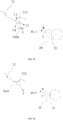
- the supported element 352 disposed at the end of the developing cartridge 32 may receive a tilted downward force F from the force-applying component 72 on the side of the main body 7, so that the supported element 352 may abut against a supporting part 345a of the drum sidewall 341. Under the action of the gravity of the developing cartridge 32 and the force F of the force-applying component 72, the supported element 352 may apply the force F to the supporting part 345a.
- the force F applied by the force-applying component 72 can be divided into a first force F1 that is perpendicular to the supporting part 345a and a second force F2 that is parallel to the supporting part 345a.
- the direction of the first force F1 may be the same as the normal direction of the contact interface between the supported element 352 and the supporting part 345a.
- the developing cartridge 32 may generate a downward rotational moment, which may be able to counteract the upward rotational moment M generated when the photosensitive drum 33 drives the developing roller 39 to rotate.
- the backward retracting force Fb of the developing roller 39 may also be counteracted.
- the present disclosure sets the pressing direction of the force-applying component 72.
- the angle ⁇ between the direction of the force F and the normal direction of the contact interface between the supported element 352 and the supporting part 345a may not be less than the friction angle between the supported element 352 and the supporting part 345a.
- the second force F2 can provide a reliable forward thrust to overcome the reverse counterforce F3 applied to the supported element 352 by the supporting part 345a and the retracting force Fb of the developing roller 39. Therefore, the clamping effect between the developing roller 39 and the photosensitive drum 33 may be ensured, and thus the imaging quality of the image forming apparatus 1 may be ensured.
- the supported element 352 may be in contact with a supporting part 345b at any position of the supporting part 345b and may have a curved contact interface. Unlike that of the supporting part 345a with a flat surface (referring to FIG. 12 ), the normal and tangential directions of the curved contact interface at different positions may be different. For this reason, it may be necessary to define an effective working area on the curved supporting part 345b, such that the supported element 352 can receive the force F from the force-applying component 72, and generate a first force F1 and a second force F2.
- the supporting part 345b may apply a counterforce F4 to the supported element 352.
- the forward tendency of the supported element 352 may be limited, and even the developing cartridge 32 may not be able to move forward, such that the clamping effect between the developing roller 39 and the photosensitive drum 33 may not be guaranteed. Therefore, at the first end of the working area, such a counterforce F4 may need to be avoided.
- the supporting part 345b may not generate a counterforce to the supported element 352.
- the supported element 352 and the supporting part 345b may be detached from each other, and thus the first force F1 and the second force F2 may not take place, and the mounting stability of the developing cartridge 32 and the processing cartridge 3 may not be ensured. Therefore, the detachment of the supported element 352 from the supporting part 345 needs to be avoided.
- the received forces are described based on a convex shaped surface of the supporting part 345b, in other embodiments, the curved surface of the supporting part 345b may have a concave shape.
- the mounting stability of the developing cartridge 32 and the processing cartridge 3 can be effectively ensured, and the thrust applied to the developing cartridge 32 by the pushing component can be reduced, thereby avoiding excessively large local stress.
- the developing roller 39 may be maintained in contact with the photosensitive drum 33 to ensure the image quality.
- the second storage unit 321 since the second storage unit 321 is disposed at a position of the bottom portion of the developing cartridge 32 that is away from the toner outlet 353, the second storage unit 321 may be in contact with and electrically connected to the second contact 41 on the side of the main body 7.
- the second contact 41 may be configured to have an elastic structure, such as a torsion spring. Therefore, when the processing cartridge 3 is mounted on the main body 7, the second contact 41 may apply an upward force to the second storage unit 321.
- the storage unit, the photosensitive drum driving gear 333, the guided section 351, and the supported element 352 may be located on the same side of the developing cartridge 32.
- the second storage unit 321 may be overlapped with at least a portion of the developing roller driving gear 392 and the photosensitive drum driving gear 333. As such, the second storage unit 321 may be closer to the side of the processing cartridge 3, and the distance from the support wall 349 may be as small as possible.
- the upward rotational torque on the second storage unit 321 generated by the second contact 41 may be limited as much as possible.
- the second storage unit 321 should also be disposed as close as possible to the end cap 355.
- the second storage unit 321 may be disposed under the end cap 355, or may be a slot integrally formed on the end cap 355 for mounting the second storage unit 321, such that the second storage unit 321, the developing roller driving gear 392, and the photosensitive drum driving gear 333, the end cap 355 may be at least partially overlapped to achieve the object of reducing the upward rotational torque on the second storage unit 321 generated by the second contact 41.
Landscapes
- Physics & Mathematics (AREA)
- General Physics & Mathematics (AREA)
- Engineering & Computer Science (AREA)
- Computer Vision & Pattern Recognition (AREA)
- Electrophotography Configuration And Component (AREA)
Description
- The present disclosure relates to the field of image forming device technology and, more particularly, relates to a developing cartridge, a processing cartridge, and an image forming apparatus.
- In particular the invention relates to a developing cartridge, detachably mountable on a photosensitive drum cartridge, the photosensitive drum cartridge being detachably mounted inside an image forming apparatus, wherein the image forming apparatus includes a force-applying component for applying a force to the developing cartridge; the photosensitive drum cartridge includes a drum holder and a photosensitive drum mounted on the drum holder, the drum holder is provided with a supporting part for mounting the developing cartridge; the developing cartridge includes a frame and a developing roller mounted on the frame, at least one side-end surface of the frame of the developing cartridge is provided with a supported element cooperating with the supporting part; when the developing cartridge and the photosensitive drum cartridge are mounted inside the image forming apparatus, the supported element receives the force applied by the force-applying component such that the developing roller is maintained pressed against the photosensitive drum; at least one sidewall of the drum holder is provided with the supporting part; and an angle between a direction of the force and a normal direction of a contact interface between the supported element and the supporting part is not smaller than a friction angle between the supported element and the supporting part.
- In addition the invention relates to a processing cartridge detachably mountable inside an image forming apparatus, comprising: a photosensitive drum cartridge; and a developing cartridge according to the invention.
- Further the invention relates to an image forming apparatus, comprising: a main body, a direction-guiding section being disposed in the main body, and a processing cartridge according to the invention.
- Document
US 6,330,410 B1 discloses a developing cartridge, a processing cartridge, and an image forming apparatus of the generic types as defined hereinabove. - An image forming apparatus is an apparatus capable of forming text and images on a printing medium. For an image forming apparatus using a photo-imaging method, a processing cartridge is the most important component. A photosensitive component in the processing cartridge can convert image information into an electronic latent image, and then convert the electronic latent image into a solid toner image and transfer the toner image to the print medium. The processing cartridge contains toner, and as the printing operation continues, the toner is gradually consumed. Therefore, the processing cartridge is a consumable item and needs to be replaced frequently.
- Currently, the common processing cartridges on the market include undetachable cartridges and detachable cartridges. Replacing an undetachable cartridge requires the user to re-purchase a processing cartridge or add toner to the processing cartridge. However, in practice, when the toner is consumed, the lifetime of the photosensitive component may still not be reached, so re-adding the toner may be the only thing needed in order to continue the use. However, for users, adding the toner may be very inconvenient, and may easily cause pollution. Therefore, with the current emphasis of environmental protection, using detachable cartridges becomes more favored.
- Although the detachable type processing cartridge is more convenient to use, during the design process, the requirements on the matching accuracy between different parts may be higher. In particular, for a developing roller in the developing cartridge and a photosensitive drum in the photosensitive drum cartridge, if the clamping effect between the developing roller and the photosensitive drum is not sufficiently ensured, the printed image may have a significant quality problem. The conventional detachable type processing cartridges and image forming apparatuses are provided with a pushing component for respectively providing forces in two different directions to push the developing cartridge such that the developing roller can be maintained in contact with the photosensitive drum, and also press the processing cartridge such that the mounting of the processing cartridge in the image forming apparatus becomes more stable. According to the existing technology, in order to resist the rotational torque generated when the photosensitive drum rotates and the thrust force of the photosensitive drum against the developing roller and also prevent the developing cartridge from being retracted back in the mounting direction, the thrust force for pushing the developing cartridge is set to be relatively large. However, this may cause the processing cartridge to be partially subjected to a relatively large counterforce of the thrust force, and the resin frame of the processing cartridge may be deformed if there is no sufficient strength to support. In addition, if the thrust force is set to be too small, the clamping force between the developing roller and the photosensitive drum may be too small, which may affect the print quality and cause blurred images.
- Document
US 2007/0071481 A1 discloses an image forming apparatus wherein a pressed area mounted on a developer cartridge case is pressed towards a developer cartridge pressing direction. A developer roller and a photosensitive drum are in contact at a contact position. - Document
US 6,330,410 B1 discloses an image forming apparatus including a photosensitive member cartridge having a case including a bottom wall, an upper wall, and side walls. A photosensitive drum and a transfer roller are rotatably disposed in a space surrounded by the bottom wall, the upper wall, and the side walls. The bottom wall extends below the transfer roller. A developer cartridge, having a developing roller, is set on the extending portion of the bottom wall. - Document
CN 201 820 074 U discloses an image forming apparatus including a drum component which comprises a drum holder and a photosensitive drum. The drum holder is provided with two end walls and a developing component mounting passage. The photosensitive drum is supported on the two end walls of the drum holder rotationally, wherein the width of a guide passage is larger than or equal to the diameter of a large positioning wheel of a developing component, each end wall is provided with a passage regulating mechanism, and the passage regulating mechanism is provided with a control portion extending into the guide passage. - Document
CN 201 170 841 Y discloses an image forming apparatus including a drum box comprising a frame body which supports a photo conductor drum rotatably and is provided with an accommodating part accommodating a developing box detachably. A pushing and pressing part is arranged on the side opposite to the photo conductor drum in the accommodating part of the frame body and pushes and presses the developing box toward the photo conductor drum. The pushing and pressing part extends throughout the width of the photo conductor drum along the Y direction of the photo conductor drum. - In view of the above problems, the present invention provides a developing cartridge, a processing cartridge, and an image forming apparatus, which provide a reasonable thrust force by a simple pushing component to realize the function for pushing the developing cartridge and the processing cartridge.
- In order to solve the above problems, the technical solution adopted by the present disclosure includes the following aspects.
- The present invention provides a developing cartridge, detachably mountable on a photosensitive drum cartridge, the photosensitive drum cartridge being detachably mounted inside an image forming apparatus, wherein the image forming apparatus includes a force-applying component for applying a force to the developing cartridge; the photosensitive drum cartridge includes a drum holder and a photosensitive drum mounted on the drum holder, and the drum holder is provided with a supporting pat for mounting the developing cartridge; the developing cartridge includes a frame and a developing roller mounted on the frame, at least one side-end surface of the frame of the developing cartridge is provided with a supported element cooperating with the supporting part; when the developing cartridge and the photosensitive drum cartridge are mounted inside the image forming apparatus, the supported element receives the force applied by the force-applying component such that the developing roller is maintained pressed against the photosensitive drum; at least one sidewall of the drum holder is provided with the supporting part; and an angle between a direction of the force and a normal direction of a contact interface between the supported element and the supporting part is not smaller than a friction angle between the supported element and the supporting part. Further the force-applying component is provided with an inclined introduction side and an inclined pressing side which incline towards two different directions respectively; the supported element is guided to the inclined pressing side through the inclined introduction side and is subjected to the force applied by the inclined pressing side; and the force generates a first force towards the supporting part and a second force towards the developing roller, the direction of the first force is opposite to the direction of a rotational moment generated when the photosensitive drum drives the developing roller to rotate, the second force makes the developing roller keep pressed against the photosensitive drum when the developing cartridge and the photosensitive drum cartridge are installed in the image forming apparatus.
- Preferably the direction of the force applied by the force-applying component is toward the mounting direction of the developing cartridge.
- Preferably the supporting part has a flat surface or a curved surface.
- Preferably the developing cartridge includes a storage unit disposed on the bottom portion of the frame. A driving gear is mounted on an axial end of the developing roller. The storage unit, the driving gear, and the supported element are located on the same side of the developing cartridge. And when the developing cartridge is viewed from a direction perpendicular to an axis of the developing roller, the storage unit is overlapped with at least a portion the driving gear.
- The present invention also provides a processing cartridge. The processing cartridge is detachably mountable inside an image forming apparatus, and comprises a photosensitive drum cartridge and a developing cartridge according to the invention, wherein the developing cartridge and the photosensitive drum cartridge are included in the processing cartridge. When the processing cartridge is mounted inside the image forming apparatus, the supported element receives the force applied by the force-applying component such that the developing roller is maintained pressed against the photosensitive drum.
- Preferably a support wall is disposed on a bottom portion of each sidewall of the drum holder. The support wall is located under the supporting part, and when the processing cartridge is mounted inside the image forming apparatus, the support wall abuts against a direction-guiding section disposed inside the image forming apparatus.
- Preferably a position-limiting protrusion is disposed at a front end of each sidewall of the drum holder. The position-limiting protrusion has a circular ring shape and is arranged concentrically with an axis of the photosensitive drum.
- The present invention also provides an image forming apparatus. The image forming apparatus includes a main body, in which a direction-guiding section is disposed, and a processing cartridge according to the invention that is detachably mounted on the main body along the direction-guiding section.
- Preferably a support wall is disposed on a bottom portion of each sidewall of the drum holder and under the supporting part. A support groove cooperating with the support wall is disposed on the direction-guiding section.
- Preferably a support bevel abutting against the support wall is disposed on a bottom portion of the support groove.
- Preferably, when the processing cartridge is viewed from a direction perpendicular to an axis of the photosensitive drum, the supported element is overlapped with at least a portion of the support wall.
- According to one of the design concepts of the present disclosure, a force is applied to the supported element by the force-applying component, and the angle between the direction of the applied force and the normal direction of the contact interface between the supported element and the supporting part is not less than the friction angle between the supported element and the supporting part. As such, it is possible to prevent undesired effects, such as deformation, breakage, etc., caused by the processing cartridge being under excessively large local stress.
- According to another design concept of the present disclosure, a force is applied to the supported element by the force-applying component, and the storage unit, the driving gear, and the supported element are disposed on the same side of the developing cartridge. When the developing cartridge is viewed from a direction perpendicular to the axis the developing roller, the storage unit is overlapped with at least a portion the driving gear, such that the force applied to the storage unit and the driving gear is as close as possible to the pressing force applied by the force-applying component to the supported element, and thus the rotational torque generated on the processing cartridge is reduced. As such, the thrust force applied by a force-applying component to the processing cartridge can be reduced, and thus it is possible to prevent undesired effects, such as deformation, breakage, etc., caused by the processing cartridge being under excessively large local stress.
- The following drawings are merely examples for illustrative purposes according to various disclosed embodiments and are not intended to limit the scope of the present disclosure.
-
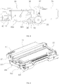
FIG. 1 illustrates a schematic structural view of an image forming apparatus according to some embodiments of the present disclosure; -
FIG. 2 illustrates a schematic diagram of the installation of a processing cartridge and an image forming apparatus according to some embodiments of the present disclosure; -
FIG. 3 illustrates a schematic cross-sectional view of an internal structure of a processing cartridge according to some embodiments of the present disclosure; -
FIG. 4 illustrates a schematic view of an overall structure of a processing cartridge according to some embodiments of the present disclosure; -
FIG. 5 illustrates a schematic structural view of a photosensitive drum cartridge according to some embodiments of the present disclosure; -
FIG. 6 illustrates a schematic structural view of a developing cartridge according to some embodiments of the present disclosure; -
FIG. 7 illustrates a schematic cross-sectional view of an image forming apparatus in a direction perpendicular to the axis of a photosensitive drum and passing through a supported element according to some embodiments of the present disclosure; -
FIG. 8 illustrates a schematic structural view of a left-side direction-guiding section inside an image forming apparatus according to some embodiments of the present disclosure; -
FIG. 9 illustrates a schematic structural view of a right-side direction-guiding section inside an image forming apparatus according to some embodiments of the present disclosure; -
FIG. 10 illustrates a schematic structural view of a locking component on a photosensitive drum cartridge according to some embodiments of the present disclosure; -
FIG. 11 illustrates a schematic cross-sectional view of an image forming apparatus in a direction perpendicular to the axis of a photosensitive drum and passing through a second storage unit according to some embodiments of the present disclosure; -
FIG. 12 illustrates a schematic diagram of an analysis of forces applied on a processing cartridge according to some embodiments of the present disclosure; and -
FIGS. 13-15 illustrate schematic diagrams of an analysis of forces applied on another processing cartridge according to some embodiments of the present disclosure. - Reference will now be made in detail to exemplary embodiments of the disclosure, which are illustrated in the accompanying drawings. Wherever possible, the same reference numbers will be used throughout the drawings to refer to the same or like parts.
- Referring to
FIGS. 1-2 , animage forming apparatus 1 may include an image forming unit, apaper feed unit 9, atransport unit 4, an image-fixingunit 5, and adischarge unit 6. In the image forming process, a paper sheet may be output from thepaper feed unit 9 and transported to the image forming unit by thetransport unit 4; the image forming unit may convert the image information into an electrostatic latent image, and further convert the electrostatic latent image into a toner image; after the toner image is transferred to the paper sheet, the paper sheet may be transferred to the image-fixingunit 5 by thetransport unit 4; after the paper sheet that carries the toner image is heated and pressed by the image-fixingunit 5, the toner image may be fixed on the paper sheet; after the completion of the image-fixing operation, the paper sheet may be finally discharged from theimage forming apparatus 1 through thedischarge unit 6. - Each of the above functional units may be mainly mounted and fixed by the frame of the
image forming apparatus 1, i.e. by amain body 7 of theimage forming apparatus 1. In one embodiment, themain body 7 may include two metal frames: a left metal frame and a right metal frame. Each functional unit may be assembled between the two metal frames, and the exterior of themain body 7 may be covered by aresin shell 8. - Referring to
FIGS. 1-4 , the image forming unit may include anexposer 2 and aprocessing cartridge 3. Theexposer 2 may be steadily mounted on themain body 7. Theprocessing cartridge 3 can be freely mounted inside or removed from the image forming apparatus. Theprocessing cartridge 3 may include aphotosensitive drum cartridge 31 and a developingcartridge 32. - The
photosensitive drum cartridge 31 may include a cylindricalphotosensitive drum 33 and adrum holder 34 for supporting and mounting thephotosensitive drum 33. Theexposer 2 may form an electrostatic latent image corresponding to image information on the surface of thephotosensitive drum 33 using laser beams. Both ends of thephotosensitive drum 33 may be mounted on thedrum holder 34 and may be rotatable after the installation. A chargingroller 37 and a cleaning component may be further provided around thephotosensitive drum 33. - The developing
cartridge 32 may be used to store toner, and may be detachably mounted on thedrum holder 34. The developingcartridge 32 may include aframe 35, and a number of structures such as atoner discharging blade 36, a rotatable developingroller 39, a stirring frame, atoner feeding roller 38, etc. may be mounted inside theframe 35. When the developingcartridge 32 is mounted on thephotosensitive drum cartridge 31, the developingroller 39 and thephotosensitive drum 33 may be in contact with other, and the driving component on theprocessing cartridge 3 may drive the developingroller 39 and thephotosensitive drum 33 to rotate simultaneously. The toner inside the developingcartridge 32 may be adhered to the developingroller 39, and by the adjustment of thetoner discharging blade 36, the toner may be transferred to the surface of thephotosensitive drum 33 that carries the electrostatic latent image at a certain thickness and quantity, thereby forming a toner image on the surface of thephotosensitive drum 33. - After the toner image is transferred to the paper sheet, the remaining toner on the surface of the
photosensitive drum 33 may be removed by the cleaning component to keep the surface of thephotosensitive drum 33 clean for the next cycle of the image forming operation. The paper sheet after the completion of the image forming operation may be transferred to the image-fixingunit 5 by thetransport unit 4. - Referring to
FIGS. 3-5 , twodrum sidewalls 341 may be disposed on the two ends of thedrum holder 34, respectively. The rear end of thedrum holder 34 may be provided with a drum rear wall for connecting the twodrum sidewalls 341, and the front end of thedrum holder 34 may be provided with a waste-toner box for storing the waste toner. The two ends of the waste-toner box may be connected to the twodrum sidewalls 341, respectively. The storage unit, the chargingroller 37, and a cleaning blade may be mounted on the waste-toner box. The two ends of thephotosensitive drum 33 may be mounted between the twodrum sidewalls 341, and thephotosensitive drum 33 may be freely rotatable around its own axis. The two ends of thephotosensitive drum 33 may both be exposed to the outside of thephotosensitive drum cartridge 31. One end of thephotosensitive drum 33 may be provided with a photosensitivedrum bias contact 331 to transfer static electricity on the surface of thephotosensitive drum 33 to themain body 7 of theimage forming apparatus 1, and the other end of thephotosensitive drum 33 may be a driving end used to receive the driving force from one side of themain body 7 and also transfer the driving force to other moving components, such as the developingroller 39, the stirring frame, etc. in theprocessing cartridge 3. - The driving end of the
photosensitive drum 33 may be provided with a photosensitivedrum driving head 332 coaxial with thephotosensitive drum 33. The photosensitivedrum driving head 332 may be used to connect the main-body driving head on one side of theimage forming apparatus 1, and receive the driving force. The photosensitivedrum driving head 332 and the rear end of the main-body driving head may be respectively provided with claw-shaped protrusions that engage with each other. The photosensitivedrum driving head 332 may also include a photosensitivedrum driving gear 333 that is integrally formed and concentric therewith. The photosensitivedrum driving gear 333 may be used to engage with other components in theprocessing cartridge 3, such as the developingroller driving gear 392, etc. for power transfer. - The movement of the main-body driving head may be interacted with the rotation of the front cover. When the front cover of the
image forming apparatus 1 is closed, the main-body driving head may extend from the main body into thephotosensitive drum cartridge 31, and may be coupled to the photosensitivedrum driving head 332 to transfer the driving force. On the contrary, when the front cover of theimage forming apparatus 1 is opened, the main-body driving head may be detached from thephotosensitive drum cartridge 31 and separated from the photosensitivedrum driving head 332, such that theprocessing cartridge 3 can be pulled out from theimage forming apparatus 1. - A position-limiting
protrusion 342 with a circular ring shape may be disposed at an outer front end of eachdrum sidewall 341, and a concave direction-guidingsection 71 may be disposed on each of the inner sidewalls of themain body 7. The position-limitingprotrusion 342 may extend out from the side surface of theprocessing cartridge 3 and may be disposed concentrically with thephotosensitive drum 33, such that as shown inFIG. 2 , during the process of mounting theprocessing cartridge 3 to theimage forming apparatus 1, the position-limitingprotrusion 342 can abut against the inner wall of the direction-guidingsection 71 and slide into theimage forming apparatus 1 along the direction-guidingsection 71. As such, the attachment and removal of theprocessing cartridge 3 may become smooth. - The
drum sidewall 341 may be provided with one or more guidinggrooves 343 for guiding the installation of the developingcartridge 32, and the guidinggroove 343 may be provided with aguiding section 344 and a supportingpart 345, respectively cooperating with the guidedsection 351 and the supportedelement 352 disposed at the side-end surface of the developingcartridge 32. The number of the guidinggrooves 343 can be set to one or two. When the number of the guidinggroove 343 is one, the guidingsection 344 may be located at a downstream position in the mounting direction of the developingcartridge 32, and the supportingpart 345 may be located at an upstream position in the mounting direction of the developingcartridge 32. According to the present disclosure, the number of the guidinggrooves 343 may be two, and the two guidinggrooves 343 may be disposed side by side in a front-rear configuration. The guidingsection 344 may be located on thefront guiding groove 343 that is closer to thephotosensitive drum 33, and the supportingpart 345 may be located on therear guiding groove 343 that is further away from thephotosensitive drum 33. The supportingpart 345 may have a flat surface or a curved surface. In the following, a detailed description of the structure of the supportingpart 345 will be provided. - When the
processing cartridge 3 is not mounted inside theimage forming apparatus 1, or when the developingcartridge 32 needs to be replaced, theprocessing cartridge 3 is generally placed on the table by the user, and thephotosensitive drum 33 may easily rub and collide against the tabletop, causing damages and finally affecting the print quality. To prevent thephotosensitive drum cartridge 31 from being damaged, four support columns may be respectively disposed at the four corner positions of the bottom portion of thephotosensitive drum cartridge 31. In one embodiment, the four support columns may be disposed on the bottom portion of thedrum sidewall 341, and among them, the twofront support columns 346 located at the front side of thephotosensitive drum cartridge 31 may be disposed under the axial end of thephotosensitive drum 33. In another embodiment, the tworear support columns 347 located at the rear side of thephotosensitive drum cartridge 31 may be disposed on the drum rear wall. - Further, in the horizontal direction, the heights of the two
rear support columns 347 at the rear side may be preferably set to be lower than the heights of the twofront support columns 346. With this arrangement, when theprocessing cartridge 3 is placed on the table top, the front side of theprocessing cartridge 3 may be upturned with respect to the rear side, and the front side of the developingcartridge 32 may also be tilted with respect to the rear side in accordance with the posture that theprocessing cartridge 3 is placed. As such, thetoner outlet 353 of the developingcartridge 32 will be placed in an upward posture, and thus the toner stored in the developingcartridge 32 may not gather at thetoner outlet 353, but may gather toward the rear side of the developingcartridge 32. Therefore, the toner may not be easily leaked to the outside of the developingcartridge 32 from thetoner outlet 353, and thus pollution may be avoided. - As shown in
FIG. 3 , in order to press the developingcartridge 32 to keep the developingroller 39 in contact with thephotosensitive drum 33, a pushing component may be provided at the rear side of thephotosensitive drum cartridge 31, and the pushing component may include aslider 41 mounted on thedrum holder 34. Theslider 41 may be able to slide in a direction perpendicular to the direction of the axis of thephotosensitive drum 33. Apush spring 42 may also be mounted on thedrum holder 34, and thepush spring 42 may push theslider 41 to slide toward the developingcartridge 32, forcing the developingroller 39 in contact with thephotosensitive drum 33 to ensure the print quality. Further, in order to ensure the developingcartridge 32 receiving a relatively stable thrust force, the front pushing surface P of theslider 41 may be configured to be flat, and correspondingly, the pushing surface at the rear side of the developingcartridge 32 may also be configured to be flat. Moreover, in the moving direction of the pushing component, the projection of the clamping interface N between the developingroller 39 and thephotosensitive drum 33 may be located within the range of the pushing surface P described above, or may be under the pushing surface P described above. In the present disclosure, "under" may refer to a direction indicated by the downstream position in the mounting direction of the developingcartridge 32. - Referring to
FIGS. 3-4 andFIG. 6 , the main part of the developingcartridge 32 may include aframe 35 made of resin. Theframe 35 may have a square structure with atoner outlet 353 disposed on the front side while the other sides are closed. As such, acavity 354 capable of containing toner may be formed. Sealing structures may be provided between thetoner outlet 353 and theframe 35, between thetoner outlet 353 and the developingroller 39, and between thetoner outlet 353 and thetoner discharging blade 36 to prevent toner from leaking. A stirring frame may be disposed in thecavity 354 to stir the toner in thecavity 354, and also move the toner toward thetoner outlet 353. Atoner feeding roller 38, a developingroller 39, and atoner discharging blade 36 may be disposed at the toner outlet 252. The two ends of each of thetoner feeding roller 38 and the developingroller 39 may be mounted on theframe 35, and thetoner feeding roller 38 and the developingroller 39 can freely rotate on theframe 35. Thetoner discharging blade 36 may be mounted on the frame using screws. Thetoner feeding roller 38 and thetoner discharging blade 36 may both be in contact with the developingroller 39, such that thetoner feeding roller 38 is able to transfer the toner to the developingroller 39. Thetoner discharging blade 36 may be able to scrape off the excess toner on the surface of the developingroller 39 to limit the output amount of the toner. - Referring to
FIG. 7 , a supportedelement 352 and a guidedsection 351 may be disposed on the side-end surface of theframe 35 to respectively cooperate with the supportingpart 345 and theguiding section 344 that are located on thephotosensitive cartridge 31. The guidedsection 351 may be disposed at a position closer to the developingroller 39. Preferably, when the guidedsection 351 is viewed from a direction parallel to the axial direction of the developingroller 39, the guidedsection 351 may be overlapped with a portion of the developingroller 39 so as to be as close as possible to the developingroller 39. When the guidedsection 351 is provided to have a cylindrical shape, the guidedsection 351 may be disposed concentrically with the developingroller 39. In this case, the axial end of the developingroller 39 may be used as the guidedsection 351 or the guidedsection 351 may be an additional part placed on the axial end of the developingroller 39. When the guidedsection 351 has a non-cylindrical shape, it may be required to at least provide oneguiding surface 351a to make contact with the surface of the guidingsection 344 and one position-limitingend 351b to limit the displacement of the guidedsection 351 in the guidinggroove 343, such that after the developingcartridge 32 is mounted on thephotosensitive drum cartridge 31, the developingcartridge 32 may be prevented from moving. - In one embodiment, the supported
element 352 and the guidedsection 351 may be integrally molded with theframe 35 by injection molding. Alternatively, the axial end of the developingroller 39 may be used as the guidedsection 351. In another embodiment of the present disclosure, anend cap 355 may be mounted on at least one side end of theframe 35. Theend cap 355 may be fixed to theframe 35 by a buckle or a screw. The supportedelement 352, the guidedsection 351, and theend cap 355 may be integrally molded by injection molding. Similarly, the guidedsection 351 may be disposed as close as possible to the developingroller 39, such that after the developingcartridge 32 is mounted to thephotosensitive drum cartridge 31, the forces applied on the developingcartridge 32 may be more stable. - In one embodiment, as the
photosensitive drum 33, the chargingroller 37, the developingroller 39, and thetoner feeding roller 38 are disposed in theprocessing cartridge 3, according to the imaging principle of a laser printer, the chargingroller 37, the developingroller 39, and thetoner feeding roller 38 may all need to be applied with a certain amount of voltage. The static electricity on thephotosensitive drum 33 may need to be transferred to themain body 7 of theimage forming apparatus 1, and therefore, theprocessing cartridge 3 may be provided with a plurality of bias contacts electrically connected to a plurality ofbias contacts 74 disposed in themain body 7. Referring toFIGS. 8-9 andFIGS. 1-6 , a plurality ofbias contacts 74 may be disposed in themain body 7, and accordingly, a plurality of bias contacts may be disposed on theprocessing cartridge 3 to electrically connect the plurality ofbias contacts 74. The plurality of bias contacts disposed on theprocessing cartridge 3 may include a charging roller bias contact 371 (referring toFIG. 4 ), a developing roller bias contact 391 (referring toFIG. 6 ), a toner feeding roller bias contact 381 (referring toFIG. 6 ), and a photosensitive drum bias contact 331 (referring toFIG. 4 ). - In order to facilitate the circuit layout of the
image forming apparatus 1, the contacts mentioned above may be disposed on the same side of theprocessing cartridge 3. In one embodiment, the bias contacts of theprocessing cartridge 3 may be arranged in a manner such that the photosensitivedrum bias contact 331 and the chargingroller bias contact 371 may be located on the sidewalls of thedrum holder 34, and the developingroller bias contact 391 and the toner feedingroller bias contact 381 may be disposed on one of the side-end surfaces of theframe 35. Preferably, on the path along which theprocessing cartridge 3 is mounted inside theimage forming apparatus 1, the photosensitivedrum bias contact 331 and the chargingroller bias contact 371 may be located closer to the downstream position than the developingroller bias contact 391 and the toner feedingroller bias contact 381. - Moreover, in a vertical plane, the photosensitive
drum bias contact 331 and the chargingroller bias contact 371 may be located on the two sides of the moving path of the developingroller bias contact 391 and the toner feedingroller bias contact 381, respectively. Further, the developingroller bias contact 391 may be located closer to the downstream position than the toner feedingroller bias contact 381. As such, in the process of mounting theprocessing cartridge 3 to theimage forming apparatus 1, thebias contacts 74 that are disposed on the sidewalls of themain body 7 and correspond to the four bias contacts on theprocessing cartridge 3, respectively may not scrape the other non-corresponding bias contacts disposed on theprocessing cartridge 3, thereby ensuring the service life of the bias contacts. Further, the photosensitivedrum bias contact 331 and the chargingroller bias contact 371 on thedrum holder 34 may be located at a lower position and a upper position of thedrum holder 34, respectively, and the developingroller bias contact 391 and the toner feedingroller bias contact 381 on theframe 35 of the developingcartridge 32 may be close to the center position of theframe 35. As such, the thrust of the bias contacts that thephotosensitive drum cartridge 31 and the developingcartridge 32 receive may be more evenly balanced. - Referring to
FIG. 10 as well asFIG. 4 andFIG. 7 , when the developingcartridge 32 and thephotosensitive drum cartridge 31 are mounted together, the user may hold the rear handle of the developingcartridge 32, align the guidedsection 351 of the developingcartridge 32 with the guidingsection 344 on thephotosensitive drum cartridge 31, and slide the guidedsection 351 along the guidingsection 344. When the developingcartridge 32 slides to a position where the developingroller 39 touches thephotosensitive drum 33, the developingcartridge 32 may not be able to move further. At this time, the user may hold the developingcartridge 32 and rotate the developingcartridge 32 with the guidedsection 351 as a rotating axis, such that the rear end of the developingcartridge 32 may fall into thephotosensitive drum cartridge 31. That is, the supportedelement 352 may fall into the supportingpart 345 in a rotating manner. As such, friction between the supportedelement 352 and the supportingpart 345 may be avoided, improving the operability of the developing cartridge installation. - Prior to installing the
processing cartridge 3 into theimage forming apparatus 1, in order to fix the developingcartridge 32 onto thephotosensitive drum cartridge 31 and prevent the developingcartridge 32 from being detached, a locking component may be further disposed on thedrum holder 34. The locking component may include a locking pole, and the locking pole may be mounted on thedrum holder 34 through a hinge. A lockinghook portion 348a, apressing portion 348b, and apositioning portion 348c may be integrally formed on the locking pole. The locking component may also include a lockingtorsion spring 348d. On end of the lockingtorsion spring 348d may be snapped onto thedrum holder 34, and the other end may be snapped onto the locking pole. - After the developing
cartridge 32 is mounted in position, under the action of the lockingtorsion spring 348d, the lockinghook portion 348a may block the return path of the developingcartridge 32, thereby preventing the developingcartridge 32 from being detached from thephotosensitive drum cartridge 31. Thepositioning portion 348c may abut against thedrum holder 34, and thus fix the position of the locking pole. The lockinghook portion 348a may abut against the developing cartridge at any position. The present disclosure provides an embodiment in which the supportedelement 352 of the developingcartridge 32 is locked by a locking pole. When thephotosensitive drum cartridge 31 needs to be taken out from the developingcartridge 31, the user may press thepressing portion 348b to release the locking of the supportedelement 352 by the locking pole, and thus the developingcartridge 32 may be easily taken out. In the meantime, the lockingtorsion spring 348d may generates an elastic restoring force, and when the user releases thepressing portion 348b, the locking pole may be automatically reset. - Referring to
FIG. 2 ,FIG. 4 ,FIG. 5 , andFIG. 7 , after the developingcartridge 32 and thephotosensitive drum cartridge 31 are mounted and fixed, the user may hold the rear end of theprocessing cartridge 3 to insert theprocessing cartridge 3 into the image forming apparatus along the direction-guidingsections 71 that are disposed on the two sidewalls inside themain body 7. Because one or more position-limitingprotrusions 342 may be disposed on the outer side of the drum sidewalls, when the position-limitingprotrusions 342 move to the far end of the direction-guidingsections 71, theprocessing cartridge 3 may not be able to move forward. According to the present disclosure, as long as the position-limitingprotrusion 342 can abut against the direction-guidingsection 71, the position-limitingprotrusion 342 may be a structure having any appropriate shape. In one embodiment, the cross section of the position-limitingprotrusion 342 may have a circular ring shape, and may be disposed around the axis of thephotosensitive drum 33. Based on such a structure, the outer diameter of the position-limitingprotrusion 342 may be the same as the width of the far end of the direction-guidingsection 71, such that theprocessing cartridge 3 may be prevented from jumping along the longitudinal direction. Therefore, through the cooperation between the position-limitingprotrusion 342 and the direction-guidingsection 71, when theprocessing cartridge 3 is mounted in position, the displacement of the front end of theprocessing cartridge 3 in the three directions may be limited, such that the installation accuracy of theprocessing cartridge 3 may be improved. Disposing the circular-ring-shaped position-limitingprotrusion 342 to surround the photosensitivedrum driving head 332 may also be able to provide protection for the photosensitivedrum driving head 332. As such, the photosensitivedrum driving head 332 may be prevented from being collided during the process of mounting theprocessing cartridge 3. Moreover, when theprocessing cartridge 3 is placed outside of theimage forming apparatus 1, the photosensitivedrum driving head 332 may be prevented from being collided by external objects. - In one embodiment, in order to ensure that the mounting of the
processing cartridge 3 in the image forming apparatus is more stable while providing thrust to keep the developingroller 39 in contact with thephotosensitive drum 33, a force-applyingcomponent 72 may be disposed on the sidewall of the direction-guidingsection 71 to provide a pushing force to theprocessing cartridge 3. The force-applyingcomponent 72 may preferably be a torsion spring. Alternatively, the force-applyingcomponent 72 may be a thrust spring. The force-applyingcomponent 72 may include two abuttingportions 72c located on the two ends, respectively, and a force-applying portion connected the two abuttingportions 72c. The abuttingportion 72c may abut against themain body 7, and the force-applying portion may further include aninclined introduction side 72a and an inclinedpressing side 72b. Compared to thepressing side 72b, theintroduction side 72a may be closer to the upstream position of the installation direction of theprocessing cartridge 3. In addition, the inclination direction of theintroduction side 72a may be opposite to the inclination direction of thepressing side 72b. The direction of the force applied by thepressing side 72b may be along the installation direction of the developingcartridge 32. - In order to achieve the object of the present disclosure, the force-applying
component 72 may apply thrust force to any position of the developingcartridge 32. However, since the force that the force-applyingcomponent 72 applies to theprocessing cartridge 3 may be large, in one embodiment, in order to make the force applied on theprocessing cartridge 3 more stable, and reduce the generation of rotational torque, the force-applyingcomponent 72 may apply the force on the supportedelement 352, such that the force that the force-applyingcomponent 72 applies to the developingcartridge 32 and theprocessing cartridge 3 may be at a position closer to the side-end of theprocessing cartridge 3. During the installation of theprocessing cartridge 3, the supportedelement 352 may first come into contact with theintroduction side 72a of the force-applyingcomponent 72, and may push the force-applyingcomponent 72 to be deformed. When the supportedelement 352 passes over the joint of theintroduction side 72a and thepressing side 72b, the force-applyingcomponent 72 may be pressed downward under the effect of its own elastic resilience, and may apply a force to the supportedelement 352 through thepressing side 72b. The force may generate a forward component and a downward component. The forward component may force the developingroller 39 in contact with thephotosensitive drum 33, and the downward component may force the supportedelement 352 to press thedrum sidewall 341 of thedrum holder 34. As such, theentire processing cartridge 3 may be pressed into themain body 7, so that theprocessing cartridge 3 may be stably installed. - As described above, through the cooperation between the position-limiting
protrusion 342 and the direction-guidingsection 71, after theprocessing cartridge 3 is mounted in position, the displacement of the front end of theprocessing cartridge 3 in the three directions may be limited. That is, displacement in the forward direction as well as in the upper and the lower directions may be limited. In order to further improve the mounting stability of theprocessing cartridge 3, the present disclosure also provides a structure for preventing theprocessing cartridge 3 from retracting back. For example, asupport wall 349 may be disposed on the bottom portion of thedrum sidewall 341 of thedrum holder 34, and asupport groove 73 may be disposed on the lower portion of the sidewall of the direction-guidingsection 71 of themain body 7. Thesupport groove 73 may be lower than the lower guiding surface of the direction-guidingsection 71. During the installation of theprocessing cartridge 3, thesupport wall 349 may be in contact with the lower guiding surface of the direction-guidingsection 71, and may slide along the lower guiding surface. After theprocessing cartridge 3 is mounted in position, theprocessing cartridge 3 may not be able to move forward, and thesupport wall 349 may be moved to a position just matching thesupport groove 73. The user may hold the rear end of theprocessing cartridge 3, and rotate theprocessing cartridge 3 downward using the axis of thephotosensitive drum 33 as a rotation center, such that thesupport wall 349 may be able to fall into thesupport groove 73. Under the action of the downward force of the force-applyingcomponent 72, thesupport wall 349 may be always held in thesupport groove 73, and theprocessing cartridge 3 may not be detached easily from themain body 7. - Further, when the
processing cartridge 3 is viewed from a direction perpendicular to the axis of thephotosensitive drum 33, the supportedelement 352 may be overlapped with at least a portion of thesupport wall 349. Through this arrangement, the downward force that the force-applyingcomponent 72 applies to the supportedelement 352 may be directly transferred to thedrum sidewall 341, and may further be transferred to the direction-guidingsection 71 from thedrum sidewall 341 through thesupport wall 349. Therefore, the downward force may be transferred in a substantially straight line without generating additional torque, so that theprocessing cartridge 3 may be more stable. In addition, when theprocessing cartridge 3 is viewed from the direction parallel to the axis of thephotosensitive drum 33, thesupport wall 349 may also be as close as possible to the supportedelement 352. - Further, a
support bevel 73a may be disposed on the bottom portion of thesupport groove 73. Thesupport bevel 73a may have a slope in a direction toward thephotosensitive drum 33. When thesupport wall 349 is installed into thesupport groove 73, thesupport wall 349 may be in contact with thesupport bevel 73a. Under the joint action of the sloping guidance of thesupport bevel 73a and the force-applyingcomponent 72, theprocessing cartridge 3 may be pushed forward, such that the mounting accuracy of theprocessing cartridge 3 may be higher. - Because the
photosensitive drum cartridge 31 and the developingcartridge 32 are both consumables, the developingcartridge 32 may need to be replaced after the toner in the developingcartridge 32 is used up, and when the waste toner stored in thephotosensitive drum cartridge 31 reaches a certain amount, thephotosensitive drum cartridge 31 may need to be replaced. Therefore, a storage unit may be disposed on each of thephotosensitive drum cartridge 31 and the developingcartridge 32. For example, a first storage unit 311 (referring toFIG. 4 ) and a second storage unit 321 (referring toFIG. 11 ) may be disposed on thephotosensitive drum cartridge 31 and the developingcartridge 32, respectively for storing information such as the toner amount, the printing amount, etc. - According to the present disclosure, the
first storage unit 311 may be disposed above the waste-toner box, and thesecond storage unit 321 may be disposed under the developingcartridge 32. Correspondingly, contacts corresponding the two storage units may be respectively disposed inside theimage forming apparatus 1. After the contacts are in contact with the storage units, electrical connection may be established, and the information in the storage units may thus be read and rewritten as the printing operation proceeds. Among these contacts, a plurality offirst contacts 22 connected to thefirst storage unit 311 may be disposed under anexposure holder 21, and a plurality ofsecond contacts 41 connected to thesecond storage unit 321 may be disposed above thetransport unit 4. - In the conventional technology, when the
processing cartridge 3 is mounted inside theimage forming apparatus 1, each storage unit and the corresponding contacts may be in contact with each other as theprocessing cartridge 3 slides, that is, sliding friction may be generated, since the contacts are all elastic structures, long-term sliding-friction contact can cause the conductive layer on the storage unit to be worn which, together the adhesion of the toner particles, can easily lead to poor communication. - According to the present disclosure, in one embodiment, as described above, when the
processing cartridge 3 is mounted on the far end of the direction-guidingsection 71, theprocessing cartridge 3 can also be rotated with the axis of thephotosensitive drum 33 as a rotation axis. In the view from the axis of thephotosensitive drum 33, thefirst storage unit 311 and thesecond storage unit 321 may be respectively located on the two opposite sides of the axis of thephotosensitive drum 33, that is, thefirst storage unit 311 and thesecond storage unit 321 may be located on the front end and the rear end of theprocessing cartridge 3, respectively. In addition, thefirst storage unit 311 and thesecond storage unit 321 may further be disposed on the upper surface and the lower surface of theprocessing cartridge 3, respectively. Therefore, during the process of mounting theprocessing cartridge 3 to theimage forming apparatus 1, thefirst storage unit 311 and thesecond storage unit 321 may not need to be in sliding contact, and when theprocessing cartridge 3 is slid to the far end of the direction-guidingsection 71, theprocessing cartridge 3 may be rotated around the axis of thephotosensitive drum 33 to finally bring thefirst storage unit 311 to be in contact with thefirst contact 22 and thesecond storage unit 321 to be in contact with thesecond contact 41, thereby avoiding sliding friction between the contacts and the storage units. - In the following, the force-balanced state in the case that the
processing cartridge 3 is mounted inside theimage forming apparatus 1 will be described with reference toFIG. 12 . Because the surface of the developingroller 39 is elastic, after theprocessing cartridge 3 is mounted inside theimage forming apparatus 1, the developingroller 39 and thephotosensitive drum 33 may need to be closely in contact with each other during operation to keep a clamping interface N formed between the developingroller 39 and thephotosensitive drum 33. The clamping interface N may ensure that the toner on the developingroller 39 can be efficiently transferred to the surface of thephotosensitive drum 33 to prevent deterioration of image quality. However, in this case, the developingroller 39 may also receive a backward retracting force Fb, forcing the developingcartridge 32 to have a tendency to move backward, such that the area of the clamping interface N sandwiched between the developingroller 39 and thephotosensitive drum 33 may become smaller, and the clamping force may be reduced. - Moreover, when the
photosensitive drum 33 receives a driving force from themain body 7 and starts rotation, the developingroller 39 may rotate together with thephotosensitive drum 33. In the direction of a line L that connects the axis of thephotosensitive drum 33 to the axis of the developingroller 39, a rotational moment M may be generated. The rotational moment M may force the rear end of the developingcartridge 32 to have a tendency to swing upward using the guidedsection 351 as a fulcrum. The rotational moment M may also cause the developingcartridge 32 to retract back, such that the area of the clamping interface N sandwiched between the developingroller 39 and thephotosensitive drum 33 may become smaller. - When the two cases described above simultaneously take place, it may be difficult to maintain an effective contact between the developing
roller 39 and thephotosensitive drum 33, which may cause the printed image to become blurred. Moreover, when theimage forming apparatus 1 is in the operation state, the installation of the developingcartridge 32 may become more unstable. - In order to solve the above problem, according to the present disclosure, the supported
element 352 disposed at the end of the developingcartridge 32 may receive a tilted downward force F from the force-applyingcomponent 72 on the side of themain body 7, so that the supportedelement 352 may abut against a supportingpart 345a of thedrum sidewall 341. Under the action of the gravity of the developingcartridge 32 and the force F of the force-applyingcomponent 72, the supportedelement 352 may apply the force F to the supportingpart 345a. The force F applied by the force-applyingcomponent 72 can be divided into a first force F1 that is perpendicular to the supportingpart 345a and a second force F2 that is parallel to the supportingpart 345a. The direction of the first force F1 may be the same as the normal direction of the contact interface between the supportedelement 352 and the supportingpart 345a. - Because the supported
element 352 has a certain distance from the guidedsection 351, under the action of the first force F1, the developingcartridge 32 may generate a downward rotational moment, which may be able to counteract the upward rotational moment M generated when thephotosensitive drum 33 drives the developingroller 39 to rotate. In the meantime, under the action of the second force F2, the backward retracting force Fb of the developingroller 39 may also be counteracted. - In addition, although the second force F2 provides a forward thrust, because the supported
element 352 is in contact with the supportingpart 345a, the supportingpart 345a may simultaneously generate a backward counterforce F3 to the supportedelement 352, preventing the supportedelement 352 from moving forward. As such, the effect of the second force F2 may be reduced, and the clamping effect between the developingroller 39 and thephotosensitive drum 33 cannot be guaranteed. To this end, the present disclosure sets the pressing direction of the force-applyingcomponent 72. For example, the angle α between the direction of the force F and the normal direction of the contact interface between the supportedelement 352 and the supportingpart 345a may not be less than the friction angle between the supportedelement 352 and the supportingpart 345a. When the materials of the supportedelement 352 and the supportingpart 345a are determined, the friction angle between the two may also be determined. - When the angle between the direction of the force F applied by the force-applying
component 72 and the normal direction of the contact interface between the supportedelement 352 and the supportingpart 345a is not less than the friction angle, the second force F2 can provide a reliable forward thrust to overcome the reverse counterforce F3 applied to the supportedelement 352 by the supportingpart 345a and the retracting force Fb of the developingroller 39. Therefore, the clamping effect between the developingroller 39 and thephotosensitive drum 33 may be ensured, and thus the imaging quality of theimage forming apparatus 1 may be ensured. - The above describes the forces applied to the
processing cartridge 3 in a case where the supportingpart 345a (referring toFIG. 12 ) has a flat surface. In the following, the forces applied to theprocessing cartridge 3 in a case that the supportingpart 345 has a curved surface will be described. - Referring to
FIGS. 13-15 , the supportedelement 352 may be in contact with a supportingpart 345b at any position of the supportingpart 345b and may have a curved contact interface. Unlike that of the supportingpart 345a with a flat surface (referring toFIG. 12 ), the normal and tangential directions of the curved contact interface at different positions may be different. For this reason, it may be necessary to define an effective working area on the curved supportingpart 345b, such that the supportedelement 352 can receive the force F from the force-applyingcomponent 72, and generate a first force F1 and a second force F2. - At a first end of the working area described above, as shown in
FIG. 14 , the supportingpart 345b may apply a counterforce F4 to the supportedelement 352. When the direction of the counterforce F4 is toward the supportedelement 352, the forward tendency of the supportedelement 352 may be limited, and even the developingcartridge 32 may not be able to move forward, such that the clamping effect between the developingroller 39 and thephotosensitive drum 33 may not be guaranteed. Therefore, at the first end of the working area, such a counterforce F4 may need to be avoided. At the other end, i.e., a second end of the working area, as shown inFIG. 15 , the supportingpart 345b may not generate a counterforce to the supportedelement 352. In this case, the supportedelement 352 and the supportingpart 345b may be detached from each other, and thus the first force F1 and the second force F2 may not take place, and the mounting stability of the developingcartridge 32 and theprocessing cartridge 3 may not be ensured. Therefore, the detachment of the supportedelement 352 from the supportingpart 345 needs to be avoided. In one embodiment, the received forces are described based on a convex shaped surface of the supportingpart 345b, in other embodiments, the curved surface of the supportingpart 345b may have a concave shape. - Through the cooperation of the force-applying
component 72, the supportedelement 352, and the supportingpart 345 of the present disclosure, the mounting stability of the developingcartridge 32 and theprocessing cartridge 3 can be effectively ensured, and the thrust applied to the developingcartridge 32 by the pushing component can be reduced, thereby avoiding excessively large local stress. In addition, the developingroller 39 may be maintained in contact with thephotosensitive drum 33 to ensure the image quality. However, since thesecond storage unit 321 is disposed at a position of the bottom portion of the developingcartridge 32 that is away from thetoner outlet 353, thesecond storage unit 321 may be in contact with and electrically connected to thesecond contact 41 on the side of themain body 7. In order to ensure desired contact between the two, thesecond contact 41 may be configured to have an elastic structure, such as a torsion spring. Therefore, when theprocessing cartridge 3 is mounted on themain body 7, thesecond contact 41 may apply an upward force to thesecond storage unit 321. - As shown in
FIGS. 7 and11 , in order to make the forces applied to theprocessing cartridge 3 more balanced and to avoid unnecessary rotational torque, the storage unit, the photosensitivedrum driving gear 333, the guidedsection 351, and the supportedelement 352 may be located on the same side of the developingcartridge 32. In addition, preferably, when the developingroller 39 is viewed from a direction perpendicular to the axis of the developingroller 39, thesecond storage unit 321 may be overlapped with at least a portion of the developingroller driving gear 392 and the photosensitivedrum driving gear 333. As such, thesecond storage unit 321 may be closer to the side of theprocessing cartridge 3, and the distance from thesupport wall 349 may be as small as possible. The upward rotational torque on thesecond storage unit 321 generated by thesecond contact 41 may be limited as much as possible. - When the developing
cartridge 32 is provided with anend cap 355, thesecond storage unit 321 should also be disposed as close as possible to theend cap 355. Preferably, thesecond storage unit 321 may be disposed under theend cap 355, or may be a slot integrally formed on theend cap 355 for mounting thesecond storage unit 321, such that thesecond storage unit 321, the developingroller driving gear 392, and the photosensitivedrum driving gear 333, theend cap 355 may be at least partially overlapped to achieve the object of reducing the upward rotational torque on thesecond storage unit 321 generated by thesecond contact 41. - The above are only the preferred embodiments of the present disclosure, and are not intended to limit the present disclosure.
- The above detailed descriptions only illustrate certain exemplary embodiments of the present disclosure, and are not intended to limit the scope of the present invention. Those skilled in the art can understand the specification as whole and technical features in the various embodiments can be combined into other embodiments understandable to those persons of ordinary skill in the art.
Claims (11)
- A developing cartridge (32), detachably mountable on a photosensitive drum cartridge (31), the photosensitive drum cartridge being detachably mounted inside an image forming apparatus (1), whereinthe image forming apparatus includes a force-applying component (72) for applying a force (F) to the developing cartridge;the photosensitive drum cartridge includes a drum holder (34) and a photosensitive drum (33) mounted on the drum holder, the drum holder is provided with a supporting part (345, 345a) for mounting the developing cartridge;the developing cartridge includes a frame (35) and a developing roller (39) mounted on the frame, at least one side-end surface of the frame of the developing cartridge is provided with a supported element (352) cooperating with the supporting part;when the developing cartridge and the photosensitive drum cartridge are mounted inside the image forming apparatus, the supported element receives the force applied by the force-applying component such that the developing roller is maintained pressed against the photosensitive drum;at least one sidewall (341) of the drum holder is provided with the supporting part; andan angle (a) between a direction of the force and a normal direction of a contact interface between the supported element and the supporting part is not smaller than a friction angle between the supported element and the supporting part; characterized in thatthe force-applying component (72) is provided with an inclined introduction side (72a) and an inclined pressing side (72b) which incline towards two different directions respectively;the supported element (352) is guided to the inclined pressing side (72b) through the inclined introduction side (72a) and is subjected to the force (F) applied by the inclined pressing side (72b); andthe force (F) generates a first force (F1) towards the supporting part and a second force (F2) towards the developing roller (39), the direction of the first force (F1) is opposite to the direction of a rotational moment generated when the photosensitive drum (33) drives the developing roller (39) to rotate, the second force (F2) makes the developing roller (39) keep pressed against the photosensitive drum (33) when the developing cartridge and the photosensitive drum cartridge are installed in the image forming apparatus (1).
- The developing cartridge according to claim 1, wherein:
the direction of the force applied by the force-applying component is toward a mounting direction of the developing cartridge. - The developing cartridge according to claim 1 or 2, wherein:
the supporting part has a flat surface or a curved surface. - The developing cartridge according to claim 1, wherein:further including a storage unit disposed on a bottom portion of the frame,a driving gear is mounted on an axial end of the developing roller;the storage unit, the driving gear, and the supported element are located on a same side of the developing cartridge; andwhen the developing cartridge is viewed from a direction perpendicular to an axis of the developing roller, the storage unit is overlapped with at least a portion the driving gear.
- A processing cartridge (3) detachably mountable inside an image forming apparatus (1), comprising:a photosensitive drum cartridge (31); anda developing cartridge (32) according to claim 1;wherein the developing cartridge and the photosensitive drum cartridge are included in the processing cartridge, wherein:
when the processing cartridge is mounted inside the image forming apparatus, the supported element receives the force applied by the force-applying component, such that the developing roller is maintained pressed against the photosensitive drum. - The processing cartridge according to claim 5, wherein:a support wall (349) is disposed on a bottom portion of the sidewall of the drum holder, and under the supporting part; andwhen the processing cartridge is mounted inside the image forming apparatus, the support wall abuts against a direction-guiding section (71) disposed inside the image forming apparatus.
- The processing cartridge according to claim 6, wherein:
a position-limiting protrusion (342) is disposed on a front end of the sidewall of the drum holder, the position-limiting protrusion has a circular ring shape and is arranged concentrically with an axis of the photosensitive drum. - An image forming apparatus (1), comprising:a main body (7), a direction-guiding section (71) being disposed in the main body, and a processing cartridge (3) according to claim 5; whereinthe processing cartridge is detachably mounted on the main body along the direction-guiding section.
- The image forming apparatus according to claim 8, wherein:a support wall (349) is disposed on a bottom portion of the sidewall of the drum holder, and under the supporting part; anda support groove (73) cooperating with the support wall is disposed on the direction-guiding section.
- The image forming apparatus according to claim 9, wherein:
a support bevel (73a) abutting against the support wall is disposed on a bottom portion of the support groove. - The image forming apparatus according to claim 9 or 10, wherein:
when the processing cartridge is viewed from a direction perpendicular to an axis of the photosensitive drum, the supported element is overlapped with at least a portion of the support wall.
Applications Claiming Priority (4)
| Application Number | Priority Date | Filing Date | Title |
|---|---|---|---|
| CN201610643941 | 2016-08-08 | ||
| CN201610666334.1A CN106154789B (en) | 2016-08-08 | 2016-08-13 | Developing box, processing box and image forming device |
| CN201620877886.2U CN206039150U (en) | 2016-08-08 | 2016-08-13 | Development cartridge , processing box and image forming device |
| PCT/CN2017/095535 WO2018028480A1 (en) | 2016-08-08 | 2017-08-02 | Developing box, processing box, and image forming device |
Publications (3)
| Publication Number | Publication Date |
|---|---|
| EP3492992A1 EP3492992A1 (en) | 2019-06-05 |
| EP3492992A4 EP3492992A4 (en) | 2020-01-01 |
| EP3492992B1 true EP3492992B1 (en) | 2021-09-29 |
Family
ID=57329981
Family Applications (1)
| Application Number | Title | Priority Date | Filing Date |
|---|---|---|---|
| EP17838610.8A Active EP3492992B1 (en) | 2016-08-08 | 2017-08-02 | Developing box, processing box, and image forming device |
Country Status (4)
| Country | Link |
|---|---|
| US (1) | US10423121B2 (en) |
| EP (1) | EP3492992B1 (en) |
| CN (1) | CN106154789B (en) |
| WO (1) | WO2018028480A1 (en) |
Families Citing this family (14)
| Publication number | Priority date | Publication date | Assignee | Title |
|---|---|---|---|---|
| CN106154789B (en) * | 2016-08-08 | 2020-07-03 | 珠海赛纳打印科技股份有限公司 | Developing box, processing box and image forming device |
| WO2018107957A1 (en) * | 2016-12-14 | 2018-06-21 | 珠海赛纳打印科技股份有限公司 | Developing box, processing box, and image forming device using processing box |
| CN111212739B (en) * | 2017-10-13 | 2022-06-21 | 惠普发展公司,有限责任合伙企业 | Unlocking consumables from a printing device based on a comparison of values extracted from a storage device |
| CN108153127B (en) * | 2017-12-28 | 2021-05-04 | 珠海奔图电子有限公司 | Developing unit, process cartridge and electronic imaging device |
| JP7472442B2 (en) | 2019-08-30 | 2024-04-23 | ブラザー工業株式会社 | Drum cartridge and image forming apparatus |
| JP7358849B2 (en) | 2019-08-30 | 2023-10-11 | ブラザー工業株式会社 | toner cartridge |
| JP7484344B2 (en) * | 2020-04-01 | 2024-05-16 | ブラザー工業株式会社 | Image forming device |
| JP7524583B2 (en) | 2020-04-01 | 2024-07-30 | ブラザー工業株式会社 | Developing cartridge |
| USD1070971S1 (en) * | 2020-08-23 | 2025-04-15 | Zhuhai Pantum Electronics Co., Ltd. | Developing box |
| JP7552398B2 (en) | 2021-02-03 | 2024-09-18 | ブラザー工業株式会社 | Image forming device |
| CN114879460B (en) * | 2021-02-05 | 2025-07-25 | 京瓷办公信息系统株式会社 | Developing device and image forming apparatus including the same |
| JP7656263B2 (en) * | 2021-05-20 | 2025-04-03 | 株式会社リコー | Image forming device |
| CN114442457A (en) * | 2022-01-23 | 2022-05-06 | 中山市瀚森打印科技有限公司 | Waste powder box and processing box |
| CN219872130U (en) * | 2022-05-04 | 2023-10-20 | 江西亿铂电子科技有限公司 | Storage component and mountable unit |
Family Cites Families (15)
| Publication number | Priority date | Publication date | Assignee | Title |
|---|---|---|---|---|
| US6330410B1 (en) * | 1999-02-26 | 2001-12-11 | Brother Kogyo Kabushiki Kaisha | Photosensitive member cartridge |
| JP2007114718A (en) * | 2005-09-26 | 2007-05-10 | Brother Ind Ltd | Image forming apparatus, process cartridge, and developing cartridge |
| JP2009180987A (en) * | 2008-01-31 | 2009-08-13 | Brother Ind Ltd | Drum cartridge |
| JP2009181002A (en) * | 2008-01-31 | 2009-08-13 | Brother Ind Ltd | Drum cartridge and developer cartridge |
| JP2009181027A (en) * | 2008-01-31 | 2009-08-13 | Brother Ind Ltd | Developer cartridge |
| CN201194071Y (en) * | 2008-04-28 | 2009-02-11 | 珠海天威技术开发有限公司 | Developing case for laser printer |
| CN201820074U (en) * | 2010-09-08 | 2011-05-04 | 珠海天威飞马打印耗材有限公司 | Drum component |
| JP5831048B2 (en) * | 2011-08-30 | 2015-12-09 | ブラザー工業株式会社 | Image forming apparatus |
| JP2016114848A (en) * | 2014-12-16 | 2016-06-23 | キヤノン株式会社 | Image formation device |
| US9411303B1 (en) * | 2015-04-10 | 2016-08-09 | Lexmark International, Inc. | Positioning stop assembly for a replaceable unit of an electrophotographic image forming device |
| JP6590534B2 (en) * | 2015-05-29 | 2019-10-16 | キヤノン株式会社 | Process cartridge and image forming apparatus |
| CN105549361A (en) * | 2015-12-31 | 2016-05-04 | 珠海奔图电子有限公司 | Storage element, developing cartridge using same, and image forming apparatus |
| JP2017167290A (en) * | 2016-03-15 | 2017-09-21 | ブラザー工業株式会社 | Development cartridge |
| CN106154789B (en) * | 2016-08-08 | 2020-07-03 | 珠海赛纳打印科技股份有限公司 | Developing box, processing box and image forming device |
| CN206039150U (en) * | 2016-08-08 | 2017-03-22 | 珠海赛纳打印科技股份有限公司 | Development cartridge , processing box and image forming device |
-
2016
- 2016-08-13 CN CN201610666334.1A patent/CN106154789B/en active Active
-
2017
- 2017-08-02 WO PCT/CN2017/095535 patent/WO2018028480A1/en not_active Ceased
- 2017-08-02 EP EP17838610.8A patent/EP3492992B1/en active Active
-
2019
- 2019-01-28 US US16/259,839 patent/US10423121B2/en active Active
Also Published As
| Publication number | Publication date |
|---|---|
| WO2018028480A1 (en) | 2018-02-15 |
| EP3492992A4 (en) | 2020-01-01 |
| CN106154789B (en) | 2020-07-03 |
| EP3492992A1 (en) | 2019-06-05 |
| US10423121B2 (en) | 2019-09-24 |
| CN106154789A (en) | 2016-11-23 |
| US20190171158A1 (en) | 2019-06-06 |
Similar Documents
| Publication | Publication Date | Title |
|---|---|---|
| US10423121B2 (en) | Developing cartridge, processing cartridge, and image forming apparatus | |
| US9720347B2 (en) | Image forming apparatus and developing cartridge | |
| US7298990B2 (en) | Process cartridge and image forming apparatus | |
| US7561817B2 (en) | Toner cartridges, development cartridges, and image forming apparatus including such cartridges | |
| CN201229471Y (en) | Drum case | |
| US12007706B2 (en) | Developing cartridge | |
| US20240176287A1 (en) | Cartridge unit | |
| CN221782565U (en) | A developing box | |
| US8897665B2 (en) | Photosensitive member unit having electrode and image forming apparatus using the same | |
| CN206162058U (en) | Developing box | |
| CN222461896U (en) | Developing box | |
| CN222979920U (en) | Developing box and drum box | |
| CN223977499U (en) | Developing box and processing box | |
| US20230350341A1 (en) | Process cartridge |
Legal Events
| Date | Code | Title | Description |
|---|---|---|---|
| STAA | Information on the status of an ep patent application or granted ep patent |
Free format text: STATUS: THE INTERNATIONAL PUBLICATION HAS BEEN MADE |
|
| PUAI | Public reference made under article 153(3) epc to a published international application that has entered the european phase |
Free format text: ORIGINAL CODE: 0009012 |
|
| STAA | Information on the status of an ep patent application or granted ep patent |
Free format text: STATUS: REQUEST FOR EXAMINATION WAS MADE |
|
| 17P | Request for examination filed |
Effective date: 20190228 |
|
| AK | Designated contracting states |
Kind code of ref document: A1 Designated state(s): AL AT BE BG CH CY CZ DE DK EE ES FI FR GB GR HR HU IE IS IT LI LT LU LV MC MK MT NL NO PL PT RO RS SE SI SK SM TR |
|
| AX | Request for extension of the european patent |
Extension state: BA ME |
|
| DAV | Request for validation of the european patent (deleted) | ||
| DAX | Request for extension of the european patent (deleted) | ||
| A4 | Supplementary search report drawn up and despatched |
Effective date: 20191129 |
|
| RIC1 | Information provided on ipc code assigned before grant |
Ipc: G03G 21/16 20060101ALI20191125BHEP Ipc: G03G 21/18 20060101ALI20191125BHEP Ipc: G03G 15/08 20060101AFI20191125BHEP |
|
| RAP1 | Party data changed (applicant data changed or rights of an application transferred) |
Owner name: ZHUHAI PANTUM ELECTRONICS CO., LTD. |
|
| RIN1 | Information on inventor provided before grant (corrected) |
Inventor name: SHAO, ZHE Inventor name: GONG, HAIFEI Inventor name: SU, CHENGJIE |
|
| STAA | Information on the status of an ep patent application or granted ep patent |
Free format text: STATUS: EXAMINATION IS IN PROGRESS |
|
| 17Q | First examination report despatched |
Effective date: 20200928 |
|
| GRAP | Despatch of communication of intention to grant a patent |
Free format text: ORIGINAL CODE: EPIDOSNIGR1 |
|
| STAA | Information on the status of an ep patent application or granted ep patent |
Free format text: STATUS: GRANT OF PATENT IS INTENDED |
|
| INTG | Intention to grant announced |
Effective date: 20210316 |
|
| GRAS | Grant fee paid |
Free format text: ORIGINAL CODE: EPIDOSNIGR3 |
|
| GRAA | (expected) grant |
Free format text: ORIGINAL CODE: 0009210 |
|
| STAA | Information on the status of an ep patent application or granted ep patent |
Free format text: STATUS: THE PATENT HAS BEEN GRANTED |
|
| AK | Designated contracting states |
Kind code of ref document: B1 Designated state(s): AL AT BE BG CH CY CZ DE DK EE ES FI FR GB GR HR HU IE IS IT LI LT LU LV MC MK MT NL NO PL PT RO RS SE SI SK SM TR |
|
| REG | Reference to a national code |
Ref country code: GB Ref legal event code: FG4D |
|
| REG | Reference to a national code |
Ref country code: CH Ref legal event code: EP Ref country code: AT Ref legal event code: REF Ref document number: 1434735 Country of ref document: AT Kind code of ref document: T Effective date: 20211015 |
|
| REG | Reference to a national code |
Ref country code: RO Ref legal event code: EPE |
|
| REG | Reference to a national code |
Ref country code: DE Ref legal event code: R096 Ref document number: 602017046920 Country of ref document: DE |
|
| REG | Reference to a national code |
Ref country code: IE Ref legal event code: FG4D |
|
| REG | Reference to a national code |
Ref country code: LT Ref legal event code: MG9D |
|
| PG25 | Lapsed in a contracting state [announced via postgrant information from national office to epo] |
Ref country code: LT Free format text: LAPSE BECAUSE OF FAILURE TO SUBMIT A TRANSLATION OF THE DESCRIPTION OR TO PAY THE FEE WITHIN THE PRESCRIBED TIME-LIMIT Effective date: 20210929 Ref country code: BG Free format text: LAPSE BECAUSE OF FAILURE TO SUBMIT A TRANSLATION OF THE DESCRIPTION OR TO PAY THE FEE WITHIN THE PRESCRIBED TIME-LIMIT Effective date: 20211229 Ref country code: NO Free format text: LAPSE BECAUSE OF FAILURE TO SUBMIT A TRANSLATION OF THE DESCRIPTION OR TO PAY THE FEE WITHIN THE PRESCRIBED TIME-LIMIT Effective date: 20211229 Ref country code: HR Free format text: LAPSE BECAUSE OF FAILURE TO SUBMIT A TRANSLATION OF THE DESCRIPTION OR TO PAY THE FEE WITHIN THE PRESCRIBED TIME-LIMIT Effective date: 20210929 Ref country code: FI Free format text: LAPSE BECAUSE OF FAILURE TO SUBMIT A TRANSLATION OF THE DESCRIPTION OR TO PAY THE FEE WITHIN THE PRESCRIBED TIME-LIMIT Effective date: 20210929 Ref country code: RS Free format text: LAPSE BECAUSE OF FAILURE TO SUBMIT A TRANSLATION OF THE DESCRIPTION OR TO PAY THE FEE WITHIN THE PRESCRIBED TIME-LIMIT Effective date: 20210929 Ref country code: SE Free format text: LAPSE BECAUSE OF FAILURE TO SUBMIT A TRANSLATION OF THE DESCRIPTION OR TO PAY THE FEE WITHIN THE PRESCRIBED TIME-LIMIT Effective date: 20210929 |
|
| REG | Reference to a national code |
Ref country code: NL Ref legal event code: MP Effective date: 20210929 |
|
| REG | Reference to a national code |
Ref country code: AT Ref legal event code: MK05 Ref document number: 1434735 Country of ref document: AT Kind code of ref document: T Effective date: 20210929 |
|
| PG25 | Lapsed in a contracting state [announced via postgrant information from national office to epo] |
Ref country code: LV Free format text: LAPSE BECAUSE OF FAILURE TO SUBMIT A TRANSLATION OF THE DESCRIPTION OR TO PAY THE FEE WITHIN THE PRESCRIBED TIME-LIMIT Effective date: 20210929 Ref country code: GR Free format text: LAPSE BECAUSE OF FAILURE TO SUBMIT A TRANSLATION OF THE DESCRIPTION OR TO PAY THE FEE WITHIN THE PRESCRIBED TIME-LIMIT Effective date: 20211230 |
|
| PG25 | Lapsed in a contracting state [announced via postgrant information from national office to epo] |
Ref country code: AT Free format text: LAPSE BECAUSE OF FAILURE TO SUBMIT A TRANSLATION OF THE DESCRIPTION OR TO PAY THE FEE WITHIN THE PRESCRIBED TIME-LIMIT Effective date: 20210929 |
|
| PG25 | Lapsed in a contracting state [announced via postgrant information from national office to epo] |
Ref country code: IS Free format text: LAPSE BECAUSE OF FAILURE TO SUBMIT A TRANSLATION OF THE DESCRIPTION OR TO PAY THE FEE WITHIN THE PRESCRIBED TIME-LIMIT Effective date: 20220129 Ref country code: SK Free format text: LAPSE BECAUSE OF FAILURE TO SUBMIT A TRANSLATION OF THE DESCRIPTION OR TO PAY THE FEE WITHIN THE PRESCRIBED TIME-LIMIT Effective date: 20210929 Ref country code: PT Free format text: LAPSE BECAUSE OF FAILURE TO SUBMIT A TRANSLATION OF THE DESCRIPTION OR TO PAY THE FEE WITHIN THE PRESCRIBED TIME-LIMIT Effective date: 20220131 Ref country code: PL Free format text: LAPSE BECAUSE OF FAILURE TO SUBMIT A TRANSLATION OF THE DESCRIPTION OR TO PAY THE FEE WITHIN THE PRESCRIBED TIME-LIMIT Effective date: 20210929 Ref country code: NL Free format text: LAPSE BECAUSE OF FAILURE TO SUBMIT A TRANSLATION OF THE DESCRIPTION OR TO PAY THE FEE WITHIN THE PRESCRIBED TIME-LIMIT Effective date: 20210929 Ref country code: ES Free format text: LAPSE BECAUSE OF FAILURE TO SUBMIT A TRANSLATION OF THE DESCRIPTION OR TO PAY THE FEE WITHIN THE PRESCRIBED TIME-LIMIT Effective date: 20210929 Ref country code: EE Free format text: LAPSE BECAUSE OF FAILURE TO SUBMIT A TRANSLATION OF THE DESCRIPTION OR TO PAY THE FEE WITHIN THE PRESCRIBED TIME-LIMIT Effective date: 20210929 Ref country code: CZ Free format text: LAPSE BECAUSE OF FAILURE TO SUBMIT A TRANSLATION OF THE DESCRIPTION OR TO PAY THE FEE WITHIN THE PRESCRIBED TIME-LIMIT Effective date: 20210929 Ref country code: AL Free format text: LAPSE BECAUSE OF FAILURE TO SUBMIT A TRANSLATION OF THE DESCRIPTION OR TO PAY THE FEE WITHIN THE PRESCRIBED TIME-LIMIT Effective date: 20210929 |
|
| REG | Reference to a national code |
Ref country code: DE Ref legal event code: R097 Ref document number: 602017046920 Country of ref document: DE |
|
| PG25 | Lapsed in a contracting state [announced via postgrant information from national office to epo] |
Ref country code: DK Free format text: LAPSE BECAUSE OF FAILURE TO SUBMIT A TRANSLATION OF THE DESCRIPTION OR TO PAY THE FEE WITHIN THE PRESCRIBED TIME-LIMIT Effective date: 20210929 |
|
| PLBE | No opposition filed within time limit |
Free format text: ORIGINAL CODE: 0009261 |
|
| STAA | Information on the status of an ep patent application or granted ep patent |
Free format text: STATUS: NO OPPOSITION FILED WITHIN TIME LIMIT |
|
| 26N | No opposition filed |
Effective date: 20220630 |
|
| PG25 | Lapsed in a contracting state [announced via postgrant information from national office to epo] |
Ref country code: SI Free format text: LAPSE BECAUSE OF FAILURE TO SUBMIT A TRANSLATION OF THE DESCRIPTION OR TO PAY THE FEE WITHIN THE PRESCRIBED TIME-LIMIT Effective date: 20210929 |
|
| PG25 | Lapsed in a contracting state [announced via postgrant information from national office to epo] |
Ref country code: MC Free format text: LAPSE BECAUSE OF FAILURE TO SUBMIT A TRANSLATION OF THE DESCRIPTION OR TO PAY THE FEE WITHIN THE PRESCRIBED TIME-LIMIT Effective date: 20210929 |
|
| REG | Reference to a national code |
Ref country code: CH Ref legal event code: PL |
|
| PG25 | Lapsed in a contracting state [announced via postgrant information from national office to epo] |
Ref country code: LU Free format text: LAPSE BECAUSE OF NON-PAYMENT OF DUE FEES Effective date: 20220802 Ref country code: LI Free format text: LAPSE BECAUSE OF NON-PAYMENT OF DUE FEES Effective date: 20220831 Ref country code: CH Free format text: LAPSE BECAUSE OF NON-PAYMENT OF DUE FEES Effective date: 20220831 |
|
| REG | Reference to a national code |
Ref country code: BE Ref legal event code: MM Effective date: 20220831 |
|
| PG25 | Lapsed in a contracting state [announced via postgrant information from national office to epo] |
Ref country code: IE Free format text: LAPSE BECAUSE OF NON-PAYMENT OF DUE FEES Effective date: 20220802 |
|
| PG25 | Lapsed in a contracting state [announced via postgrant information from national office to epo] |
Ref country code: BE Free format text: LAPSE BECAUSE OF NON-PAYMENT OF DUE FEES Effective date: 20220831 |
|
| PG25 | Lapsed in a contracting state [announced via postgrant information from national office to epo] |
Ref country code: HU Free format text: LAPSE BECAUSE OF FAILURE TO SUBMIT A TRANSLATION OF THE DESCRIPTION OR TO PAY THE FEE WITHIN THE PRESCRIBED TIME-LIMIT; INVALID AB INITIO Effective date: 20170802 |
|
| PG25 | Lapsed in a contracting state [announced via postgrant information from national office to epo] |
Ref country code: SM Free format text: LAPSE BECAUSE OF FAILURE TO SUBMIT A TRANSLATION OF THE DESCRIPTION OR TO PAY THE FEE WITHIN THE PRESCRIBED TIME-LIMIT Effective date: 20210929 Ref country code: MK Free format text: LAPSE BECAUSE OF FAILURE TO SUBMIT A TRANSLATION OF THE DESCRIPTION OR TO PAY THE FEE WITHIN THE PRESCRIBED TIME-LIMIT Effective date: 20210929 Ref country code: CY Free format text: LAPSE BECAUSE OF FAILURE TO SUBMIT A TRANSLATION OF THE DESCRIPTION OR TO PAY THE FEE WITHIN THE PRESCRIBED TIME-LIMIT Effective date: 20210929 |
|
| PG25 | Lapsed in a contracting state [announced via postgrant information from national office to epo] |
Ref country code: MT Free format text: LAPSE BECAUSE OF FAILURE TO SUBMIT A TRANSLATION OF THE DESCRIPTION OR TO PAY THE FEE WITHIN THE PRESCRIBED TIME-LIMIT Effective date: 20210929 |
|
| PGFP | Annual fee paid to national office [announced via postgrant information from national office to epo] |
Ref country code: DE Payment date: 20250820 Year of fee payment: 9 |
|
| PGFP | Annual fee paid to national office [announced via postgrant information from national office to epo] |
Ref country code: TR Payment date: 20250728 Year of fee payment: 9 Ref country code: IT Payment date: 20250825 Year of fee payment: 9 |
|
| PGFP | Annual fee paid to national office [announced via postgrant information from national office to epo] |
Ref country code: GB Payment date: 20250821 Year of fee payment: 9 |
|
| PGFP | Annual fee paid to national office [announced via postgrant information from national office to epo] |
Ref country code: FR Payment date: 20250828 Year of fee payment: 9 |
|
| PGFP | Annual fee paid to national office [announced via postgrant information from national office to epo] |
Ref country code: RO Payment date: 20250725 Year of fee payment: 9 |