EP3492890A1 - Infrared spectrophotometer and method of storing window member - Google Patents
Infrared spectrophotometer and method of storing window member Download PDFInfo
- Publication number
- EP3492890A1 EP3492890A1 EP18205613.5A EP18205613A EP3492890A1 EP 3492890 A1 EP3492890 A1 EP 3492890A1 EP 18205613 A EP18205613 A EP 18205613A EP 3492890 A1 EP3492890 A1 EP 3492890A1
- Authority
- EP
- European Patent Office
- Prior art keywords
- window member
- lid member
- opening
- window
- sample chamber
- Prior art date
- Legal status (The legal status is an assumption and is not a legal conclusion. Google has not performed a legal analysis and makes no representation as to the accuracy of the status listed.)
- Granted
Links
Images






Classifications
-
- G—PHYSICS
- G01—MEASURING; TESTING
- G01J—MEASUREMENT OF INTENSITY, VELOCITY, SPECTRAL CONTENT, POLARISATION, PHASE OR PULSE CHARACTERISTICS OF INFRARED, VISIBLE OR ULTRAVIOLET LIGHT; COLORIMETRY; RADIATION PYROMETRY
- G01J3/00—Spectrometry; Spectrophotometry; Monochromators; Measuring colours
- G01J3/02—Details
- G01J3/0291—Housings; Spectrometer accessories; Spatial arrangement of elements, e.g. folded path arrangements
-
- G—PHYSICS
- G01—MEASURING; TESTING
- G01J—MEASUREMENT OF INTENSITY, VELOCITY, SPECTRAL CONTENT, POLARISATION, PHASE OR PULSE CHARACTERISTICS OF INFRARED, VISIBLE OR ULTRAVIOLET LIGHT; COLORIMETRY; RADIATION PYROMETRY
- G01J3/00—Spectrometry; Spectrophotometry; Monochromators; Measuring colours
- G01J3/02—Details
- G01J3/0202—Mechanical elements; Supports for optical elements
-
- G—PHYSICS
- G01—MEASURING; TESTING
- G01J—MEASUREMENT OF INTENSITY, VELOCITY, SPECTRAL CONTENT, POLARISATION, PHASE OR PULSE CHARACTERISTICS OF INFRARED, VISIBLE OR ULTRAVIOLET LIGHT; COLORIMETRY; RADIATION PYROMETRY
- G01J3/00—Spectrometry; Spectrophotometry; Monochromators; Measuring colours
- G01J3/02—Details
- G01J3/0286—Constructional arrangements for compensating for fluctuations caused by temperature, humidity or pressure, or using cooling or temperature stabilization of parts of the device; Controlling the atmosphere inside a spectrometer, e.g. vacuum
-
- G—PHYSICS
- G01—MEASURING; TESTING
- G01J—MEASUREMENT OF INTENSITY, VELOCITY, SPECTRAL CONTENT, POLARISATION, PHASE OR PULSE CHARACTERISTICS OF INFRARED, VISIBLE OR ULTRAVIOLET LIGHT; COLORIMETRY; RADIATION PYROMETRY
- G01J3/00—Spectrometry; Spectrophotometry; Monochromators; Measuring colours
- G01J3/28—Investigating the spectrum
- G01J3/42—Absorption spectrometry; Double beam spectrometry; Flicker spectrometry; Reflection spectrometry
-
- G—PHYSICS
- G01—MEASURING; TESTING
- G01J—MEASUREMENT OF INTENSITY, VELOCITY, SPECTRAL CONTENT, POLARISATION, PHASE OR PULSE CHARACTERISTICS OF INFRARED, VISIBLE OR ULTRAVIOLET LIGHT; COLORIMETRY; RADIATION PYROMETRY
- G01J3/00—Spectrometry; Spectrophotometry; Monochromators; Measuring colours
- G01J3/28—Investigating the spectrum
- G01J3/45—Interferometric spectrometry
- G01J3/453—Interferometric spectrometry by correlation of the amplitudes
-
- G—PHYSICS
- G01—MEASURING; TESTING
- G01J—MEASUREMENT OF INTENSITY, VELOCITY, SPECTRAL CONTENT, POLARISATION, PHASE OR PULSE CHARACTERISTICS OF INFRARED, VISIBLE OR ULTRAVIOLET LIGHT; COLORIMETRY; RADIATION PYROMETRY
- G01J5/00—Radiation pyrometry, e.g. infrared or optical thermometry
- G01J5/02—Constructional details
- G01J5/08—Optical arrangements
- G01J5/0875—Windows; Arrangements for fastening thereof
Definitions
- the present invention relates to an infrared spectrophotometer which irradiates a sample in a sample chamber with infrared light and detects light from the sample with a detector and a method of storing a window member in the infrared spectrophotometer.
- a Fourier transform infrared spectrophotometer which is an example of an infrared spectrophotometer is provided with a sample chamber for placing a sample, and a sample in the sample chamber is irradiated with infrared light. Then, a spectrum can be obtained by detecting transmitted light or reflected light from the sample with a detector and performing calculation based on the detection signal.
- FTIR Fourier transform infrared spectrophotometer
- the infrared light with which the sample in the sample chamber is irradiated is formed into interference light by using a movable mirror, a fixed mirror, a beam splitter, and the like, and then transmitted through the window member to be applied into the sample chamber.
- Optical components such as a movable mirror, a fixed mirror, and a beam splitter are disposed in a space (interferometer chamber) formed in the housing.
- a partition wall is provided in the housing, and the sample chamber and the interferometer chamber are partitioned by the partition wall.
- the window member is attached to an opening formed in the partition wall and transmits the interference light generated in the interferometer chamber to the sample chamber.
- a window member is generally attached to a device via a screw mechanism.
- potassium bromide KBr which is inexpensive and has high infrared light transmittance is often used. This potassium bromide has the property of having high deliquescence and hence being easily deliquesced depending on the humidity of the surrounding environment (see, for example, JP-A-2010-237168 ).
- the space in which the device is disposed is constantly air-conditioned or the window member is discarded when it is deliquesced.
- such operations lead to increases in the cost of the electricity bill and the cost of the window member. For this reason, when the device is not in use, the window member is detached from the device and stored in a low-humidity environment.
- the window member In detaching the window member with high deliquescence like the above potassium bromide, if a user touches the window member with his/her hand, the window member deliquesces with the humidity of the hand. Since the window member is firmly attached to the device, a large force is required for detachment. For this reason, a dedicated tool is generally used for attaching and detaching the window member. In addition, in changing the window member to a window member with a different transmission wavelength, the window member is detached and attached by using the dedicated tool.
- the window member When the device is not used, the window member is detached from the device by using the dedicated tool as described above, and a lid member is attached to the opening of the partition wall after the window member is detached. Since the interferometer chamber is kept in a dry and airtight state by attaching the lid member to the opening and providing a moisture absorption mechanism in the interferometer chamber, it is possible to prevent deterioration in optical components (for example, a beam splitter) made of a material with high deliquescence like the window member.
- optical components for example, a beam splitter
- the operation of detaching the window member from the device when it is not in use and reattaching the window member when the device is used is very cumbersome.
- the window member attached to the device with a screw mechanism is attached and detached by using the dedicated tool for attaching and detaching the window member.
- the window member may be excessively rotated to be damaged.
- a low-humidity environment for storing the window member detached from the device must be prepared. Therefore, there is a problem that the window member cannot be easily stored in a low-humidity environment.
- the present invention has been made in view of the above circumstances, and an object of the present invention is to provide an infrared spectrophotometer that can easily store a window member in a low-humidity environment and a method of storing the window member. Another object of the present invention is to provide an infrared spectrophotometer that can easily store a window member, and attach and detach the window member.
- engaging the lid member with the window member attached to the opening from the side of the sample chamber can cover the side of the sample chamber of the window member with the lid member.
- accommodating a moisture absorbent in the space can prevent the window member from deteriorating due to the humidity of the surrounding environment. Therefore, the window member can be easily stored in a low-humidity environment without being detached.
- the window member can be fixed to the opening by using the lid member. That is, while the window member can be covered with the lid member when being stored, the window member can be attached and detached by using the lid member. Therefore, it is easy to store the window member, and attach and detach the window member. Further, there is no need to separately prepare a dedicated tool for attaching and detaching the window member.
- the window member can be fixed to the opening only by inserting the window member into the opening and rotating the lid member in the one direction while the window member is attached to the lid member, and the lid member can be detached from the window member. This further facilitates attaching and detaching the window member.
- the space formed inside the lid member can easily be set in a substantially airtight state. This further facilitates storing the window member.
- the window member can be easily detached from the opening only by rotating the lid member in the direction opposite to the one direction from a state in which the window member is covered with the lid member and stored. This further facilitates attaching and detaching the window member.
- the protrusion engages with the positioning hole and can be easily fixed to the opening only by inserting the protrusion formed on the window member into the positioning hole of the partition wall and rotating the lid member.
- the window member can always be fixed at the same position without excessively rotating the lid member unlike the case of using the screw mechanism, thereby preventing the window member from being damaged.
- the lid member when the window member is not attached to the opening, for example, during transportation or storage, the lid member is turned to the other side and the closing portion is inserted into the opening, thereby closing the opening.
- This can make the interferometer chamber in the housing into an enclosed space, and hence can prevent deterioration of the disposed optical component due to humidity.
- the present invention it is possible to prevent a window member from deteriorating due to the humidity of the surrounding environment by accommodating a moisture absorbent in a space formed inside a lid member, and hence to easily store the window member in a low-humidity environment without detaching the window member.
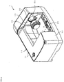
- Fig. 1 is a perspective view showing the overall configuration of an infrared spectrophotometer 1 according to an embodiment of the present invention.
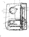
- Fig. 2 is a sectional view taken along line A-A of the infrared spectrophotometer 1 in Fig. 1 .
- the infrared spectrophotometer 1 is, for example, a Fourier transform infrared spectrophotometer (FTIR), and its outer shape is partitioned by a rectangular parallelepiped housing 10.
- FTIR Fourier transform infrared spectrophotometer
- a concave portion is formed in a portion of a wall surface of the housing 10, and a space in the concave portion constitutes a sample chamber 20.
- the sample chamber 20 can be opened and closed by a cover (not shown).
- a user can perform work on the housing 10 from the front.
- the cover is provided over an upper surface 11 and a front surface 12 of the housing 10. Opening the cover will open the upper and the front of the sample chamber 20.
- a sample can be loaded in and unloaded from the sample chamber 20.
- the sample in the sample chamber 20 can be irradiated with infrared light and the light from the sample is detected by a detector (not shown), thereby analyzing the sample.
- the housing 10 is a hollow member, and interferometer chambers 13 and 14 for accommodating various optical components are formed on both right and left sides of the sample chamber 20.
- the interferometer chamber 13 is provided with optical components constituting a Michelson interferometer including a light source, a movable mirror, a fixed mirror, and a beam splitter (none of them are shown). Infrared light emitted from the light source is formed into interference light by using the movable mirror, the fixed mirror, the beam splitter, and the like, and then transmitted through a window member 30 (see Fig. 2 ) to be applied into the sample chamber 20.
- the interferometer chamber 14 is provided with optical components such as the detector described above.
- a laser light source as a reference light source is provided in the housing 10. In order to comply with laser safety standards, an interlock is required to be provided at an opening where a human body may be exposed to laser light.
- the window member 30 is covered with a lid member 40 from a side of the sample chamber 20.
- This state is a state when the infrared spectrophotometer 1 is stored, and the lid member 40 is detached when the infrared spectrophotometer 1 is to be used.
- the lid member 40 is attachable to and detachable from the window member 30.
- the lid member 40 is formed of, for example, a metal. However, the configuration is not limited to this.
- the lid member 40 may be formed of a material other than a metal.
- the housing 10 has a partition wall 15 constituting the wall surface of the sample chamber 20.
- the sample chamber 20 is partitioned by the partition wall 15 with respect to the interferometer chambers 13 and 14. That is, the interferometer chambers 13 and 14 are formed on the opposite side to the sample chamber 20 with respect to the partition wall 15.
- the window member 30 is attachable to and detachable from an opening 151 formed in the partition wall 15, and light can be transmitted between the sample chamber 20 and the interferometer chamber 13 while the window member 30 is attached to the opening 151.
- the interference light generated in the interferometer chamber 13 is transmitted through the window member 30 and is applied on the sample in the sample chamber 20.
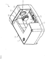
- Fig. 3 is a perspective view showing the overall configuration of the infrared spectrophotometer 1 and its state at the time of shipment. In Fig. 3 as well, an illustration of a cover (not shown) for opening and closing the sample chamber 20 is omitted.
- the lid member 40 is attached to the opening 151 of the partition wall 15 in a manner different from that in Fig. 1 . Specifically, as the lid member 40 is turned to the other side, the end portion of the lid member 40 on the opposite side to the side where the window member 30 is attached is inserted into the opening 151. At this time, the window member 30 is not attached to the opening 151, and the infrared spectrophotometer 1 can be shipped out and transported with the opening 151 closed by the lid member 40.
- Fig. 4 is a perspective view showing the overall configuration of the infrared spectrophotometer 1 and its state immediately before the attachment of the window member 30 to the opening 151.
- Fig. 5 is a perspective view showing the overall configuration of the infrared spectrophotometer 1 and a state in which the window member 30 is attached to the opening 151.
- an illustration of a cover (not shown) for opening and closing the sample chamber 20 is omitted.
- the lid member 40 in the state shown in Fig. 3 is detached, and the window member 30 is attached to the lid member 40. Then, as shown in Fig. 4 , the window member 30 attached to the lid member 40 is inserted toward the opening 151 of the partition wall 15. Thereafter, by rotating the lid member 40, the window member 30 is rotated and fixed to the opening 151, and after the fixing, the lid member 40 is detached from the window member 30.
- the window member 30 is fixed to the opening 151, and light can be transmitted between the sample chamber 20 and the interferometer chamber 13.
- the window member 30 is attached to the lid member 40, the window member 30 is fixed to the opening 151 by using the lid member 40, and the lid member 40 is then detached from the window member 30.
- Fig. 6 is a sectional view taken along B-B of the infrared spectrophotometer 1 in Fig. 1 , showing a state in which the window member 30 is not attached to the opening 151.
- a positioning hole 152 for positioning and fixing the window member 30 is formed in the peripheral edge portion of the opening 151 in the partition wall 15.
- a positioning protrusion (not shown) provided on the window member 30 is inserted into the positioning hole 152, and as the window member 30 rotates, the protrusion engages with the positioning hole 152.
- the window member 30 is positioned and fixed in the opening 151.
- the positioning hole 152 has a shape obtained by joining a large-diameter first hole 153 and a small-diameter second hole 154 each having a circular hole.
- the first hole 153 and the second hole 154 are formed so as to be aligned in the circumferential direction of the circular opening 151.
- Fig. 7A is a perspective view showing a specific configuration of the lid member 40.
- Fig. 7B is a perspective view of the lid member 40 viewed from a direction different from that in Fig. 7A .
- Fig. 7C is a sectional view taken along line C-C of the lid member 40 in Fig. 7A .
- the lid member 40 has a cylindrical main body 41. One end face of the main body 41 is opened by forming a circular opening 42. The other end face of the main body 41 is closed by a closing portion 43. An annular grip portion 44 is formed on the outer circumferential surface of the main body 41 so as to protrude radially outward. When rotating the lid member 40, the user can grip the grip portion 44 and easily rotate the lid member 40.
- An annular flange portion 45 is formed on the inner circumferential surface of the main body 41 so as to protrude radially inward.
- a space in the main body 41 which is closer to the opening 42 than the flange portion 45 constitutes a window member accommodating space 46 for accommodating the window member 30. That is, the window member 30 is inserted into the main body 41 of the lid member 40 from the opening 42, and is brought into contact with the flange portion 45 by being accommodated in the window member accommodating space 46.
- a plurality of engaging protruding portions 47 are formed on the inner circumferential surface of the main body 41 in the window member accommodating space 46.
- Each of the engaging protruding portions 47 extends in the circumferential direction along the inner circumferential surface of the main body 41.
- the engaging protruding portions 47 are formed at equal intervals in the circumferential direction.
- a space in the main body 41 which is closer to the closing portion 43 than the flange portion 45 constitutes a moisture absorbent accommodating space 48 for accommodating a moisture absorbent such as silica gel.
- a moisture absorbent such as silica gel.
- a seal member 49 constituted by, for example, an O-ring is attached to the outer circumferential surface of the closing portion 43.
- the lid member 40 from which the window member 30 is detached is inserted into the opening 151 from the closing portion 43 side to close the opening 151 with the closing portion 43.
- the seal member 49 provided on the outer circumferential surface of the closing portion 43 comes into tight contact with the peripheral edge portion of the opening 151, thereby setting the inside of the housing 10 (the interferometer chamber 13) in an airtight state.
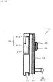
- Fig. 8A is a perspective view showing a specific configuration of the window member 30.
- Fig. 8B is a perspective view of the window member 30 viewed from a direction different from that in Fig. 8A .
- Fig. 8C is a sectional view taken along line D-D of the window member 30 of Fig. 8A .
- the window member 30 has an annular main body 31, a circular light transmitting plate 32 provided in the main body 31, and a fixing plate 33 for fixing the light transmitting plate 32 to the main body 31.
- An annular stepped portion is formed on the inner circumferential surface of the main body 31, and the light transmitting plate 32 is in contact with a seal member 34 such as an O-ring provided on the stepped portion.
- the annular fixing plate 33 is then attached to the main body 31 from the outside, and the light transmitting plate 32 is pressed against the seal member 34 side by the fixing plate 33, thereby air-tightly closing one end face of the main body 31 with the light transmitting plate 32.
- the fixing plate 33 is fixed to the main body 31 by using a fixture 35 such as a screw.
- the fixture 35 is inserted into a through hole formed in the fixing plate 33 and fixed to the main body 31 by being, for example, screwed into the main body 31 to sandwich and fix the fixing plate 33 between the fixture 35 and the main body 31.
- the fixing plate 33 is fixed by using a plurality (for example, three) of fixtures 35.
- One of the plurality of fixtures 35 constitutes a protrusion 351 protruding more than the remaining fixtures 35.
- the protrusion 351 is inserted into and engaged with the positioning hole 152, thereby fixing the window member 30 to the opening 151.
- the protrusion 351 is formed by using the fixture 35 for fixing the light transmitting plate 32 to the main body 31.
- the present invention is not limited to such a configuration, and may be provided with the protrusion 351 independently of the fixture 35.
- the light transmitting plate 32 is made of, for example, potassium bromide (KBr). Potassium bromide has advantages of being inexpensive and high in infrared light transmittance and has the property of having high deliquescence and hence easily deliquescing depending on the humidity of the surrounding environment. Although the material of the light transmitting plate 32 is not limited to potassium bromide, the present invention is particularly effective when the light transmitting plate 32 is formed of a material with high deliquescence.
- Engaging groove portions 36 that engage with the engaging protruding portions 47 of the lid member 40 are formed on the outer circumferential surface of the main body 31.
- the number of engaging groove portions 36 is the same as the number of the engaging protruding portions 47, and may be single or plural.
- Each of the engaging groove portions 36 extends in the circumferential direction along the outer circumferential surface of the main body 31.
- the engaging groove portions 36 are formed at equal intervals in the circumferential direction.
- Each of the engaging groove portions 36 has a shape obtained by joining a first groove portion 361 and a second groove portion 362.
- the length of the first groove portion 361 in the circumferential direction is longer than that of the engaging protruding portion 47.
- the first groove portion 361 is opened toward the end face 311 on the opposite side to the light transmitting plate 32 side of the main body 31.
- the second groove portion 362 communicates with the first groove portion 361 in the circumferential direction. Unlike the first groove portion 361, the second groove portion 362 is not opened toward the end face 311 side of the main body 31. Accordingly, after the engaging protruding portion 47 of the lid member 40 is received in the first groove portion 361, the window member 30 is relatively rotated to move the engaging protruding portion 47 into the second groove portion 362, thereby engaging the engaging protruding portion 47 with the engaging groove portion 36 (the second groove portion 362).
- a magnet mounting portion 37 for mounting a magnet 38 is formed on a portion of the outer circumferential surface of the main body 31, a magnet mounting portion 37 for mounting a magnet 38 is formed.
- the magnet mounting portion 37 is constituted by, for example, a concave portion formed in the outer circumferential surface of the main body 31, and the magnet 38 is inserted and mounted in the magnet mounting portion 37 (see Fig. 8C ).
- a magnetic force detector (not shown) for detecting the magnetic force of the magnet 38 is provided near the opening 151 in the housing 10.
- the magnetic force detector detects the magnetic force of the magnet 38 while the window member 30 is normally attached to the opening 151.
- the lock function provided for the laser light source as the reference light source is released. This makes it possible to emit laser light from the laser light source upon confirming that the window member 30 is normally attached to the opening 151, thereby preventing the human body from being exposed to the laser light through the opening 151.
- a seal member 39 constituted by, for example, an O-ring is attached to the outer circumferential surface of the main body 31.
- the seal member 39 has substantially the same outer diameter as that of the seal member 49 provided on the lid member 40. Accordingly, while the window member 30 is normally attached to the opening 151, the seal member 39 provided on the outer circumferential surface of the window member 30 comes into tight contact with the peripheral edge portion of the opening 151, thereby setting the inside of the housing 10 (the interferometer chamber 13) in an airtight state.
- Fig. 9 is a perspective view showing a state in which the lid member 40 and the window member 30 are detached.
- Fig. 10A is a perspective view showing a state in which the lid member 40 and the window member 30 are attached.
- Fig. 10B is a perspective view showing a state in which the lid member 40 and the window member 30 are attached, when viewed from a direction different from that in Fig. 10A .
- Fig. 10C is a sectional view taken along line E-E of the lid member 40 and the window member 30 in Fig. 10A .
- the window member 30 and the lid member 40 are coaxially disposed such that the engaging protruding portions 47 of the lid member 40 face the engaging groove portions 36 of the window member 30, as shown in Fig. 9 .
- the respective engaging protruding portions 47 are received in the first groove portions 361 of the respective engaging groove portions 36.
- the window member 30 is rotated in the counterclockwise direction in Fig. 9 .
- the engaging protruding portions 47 positioned in the first groove portions 361 of the engaging groove portions 36 move into the second groove portions 362, and the engaging protruding portions 47 engage with the engaging groove portions 36 (the second groove portions 362), as shown in Figs. 10A to 10C .
- the user grips the grip portion 44 of the lid member 40, inserts the window member 30 into the opening 151 of the partition wall 15, and fixes the window member 30 in the opening 151.
- the protrusion 351 of the window member 30 protrudes to the opposite side to the lid member 40 side.
- the protrusion 351 is inserted first into the first hole 153 (see Fig. 6 ) of the positioning hole 152 formed in the peripheral edge portion of the opening 151, and the lid member 40 is then rotated in the clockwise direction in Fig. 10A , thereby moving the protrusion 351 from the first hole 153 to the second hole 154 and engaging the protrusion 351 with the second hole 154.
- Figs. 11A and 11B are views each showing the positional relationship between the engaging protruding portion 47 and the engaging groove portions 36 when the window member 30 is attached to and detached from the opening 151.
- Figs. 12A and 12B are views each showing the positional relationship between the protrusion 351 and the positioning hole 152 when the window member 30 is attached to and detached from the opening 151.
- the engaging protruding portion 47 engages with the second groove portion 362 of the engaging groove portion 36, as shown in Fig. 11A .
- the protrusion 351 of the window member 30 is positioned in the first hole 153 of the positioning hole 152, as shown in Fig. 12A .
- the rotational position of the window member 30 (the rotational angle relative to the opening 151) is the first rotational position. That is, at the first rotational position, the engaging protruding portion 47 is positioned in the first groove portion 361 of the engaging groove portion 36 (see Fig. 11B ), and the protrusion 351 is positioned in the first hole 153 of the positioning hole 152 (see Fig. 12A ). In this state, the engagement state of the lid member 40 with respect to the window member 30 is released, but the window member 30 is not yet fixed to the opening 151.
- the lid member 40 is further rotated in the clockwise direction (one direction) in Fig. 12A , while the engaging protruding portion 47 is positioned in the first groove portion 361 of the engaging groove portion 36, the protrusion 351 moves to the second hole 154 of the positioning hole 152.
- the rotational position of the window member 30 at this time is the second rotational position. That is, at the second rotational position, the engaging protruding portion 47 is positioned in the first groove portion 361 of the engaging groove portion 36 (see Fig. 11B ), and the protrusion 351 is positioned in the second hole 154 of the positioning hole 152 (see Fig. 12B ). In this state, the protrusion 351 fits into the second hole 154 of the positioning hole 152 to fix the window member 30 to the opening 151.
- the lid member 40 can be easily detached from the window member 30 by separating the lid member 40 from the window member 30 fixed to the opening 151. As a result, as shown in Fig. 5 , only the window member 30 is attached to the opening 151, and infrared light can be applied into the sample chamber 20 via the window member 30.
- the window member 30 When the infrared spectrophotometer 1 is not used, it is preferable to store the window member 30 in a low-humidity environment in order to prevent the light transmitting plate 32 of the window member 30 from deteriorating due to deliquescence or the like. In this case, the window member 30 can be detached from the opening 151 and moved to a low-humidity environment. However, in this embodiment, while the window member 30 is fixed to the opening 151, the window member 30 can be stored by using the lid member 40.
- the lid member 40 is brought close to the window member 30 fixed to the opening 151 in the state shown in Fig. 12B , and the engaging protruding portion 47 of the lid member 40 is inserted into the first groove portion 361 of the engaging groove portion 36 of the window member 30.
- the window member 30 is at the second rotational position (see Figs. 11B and 12B ).
- the lid member 40 is rotated in the counterclockwise direction in Fig. 12B (direction opposite to the one direction) from this state, the engaging protruding portion 47 moves from the first groove portion 361 of the engaging groove portion 36 to the second groove portion 362 (see Fig. 11A ).
- the protrusion 351 of the window member 30 is kept fitted in the second hole 154 of the positioning hole 152, the window member 30 is kept fixed in the opening 151.
- the substantially airtight state may be a state in which the moisture absorbent stored in the moisture absorbent accommodating space 48 maintains the inside of the moisture absorbent accommodating space 48 in a low-humidity environment to the extent that the window member does not deteriorate. This state is not limited to a completely enclosed state but includes a state in which outside air can enter and exit the moisture absorbent accommodating space 48 to some extent.
- the lid member 40 engages with the window member 30 attached to the opening 151 from a side of the sample chamber 20, so that the side of the sample chamber 20 of the window member 30 is covered with the lid member 40, and the moisture absorbent accommodating space 48 is set in a substantially airtight state. Accordingly, if the moisture absorbent is stored in the moisture absorbent accommodating space 48, the window member 30 can be stored in a low-humidity environment.
- the moisture absorbent is stored in advance in the moisture absorbent accommodating space 48 in the lid member 40 (moisture absorbent accommodating step), and the lid member 40 engages with the window member 30 attached to the opening 151 from the side of the sample chamber 20, thus covering the side of the sample chamber 20 of the window member 30 with the lid member 40 (lid member engaging step).
- the moisture absorbent may be stored in the moisture absorbent accommodating space 48.
- the window member 30 can be detached from the opening 151.
- the lid member 40 is further rotated in the counterclockwise direction in Fig. 12B , while the engaging protruding portion 47 is positioned in the second groove portion 362 of the engaging groove portion 36, the protrusion 351 moves to the second hole 154 of the positioning hole 152 to the first hole 153 (see Figs. 11A and 12A ).
- the window member 30 can be detached from the opening 151, together with the lid member 40, by separating the lid member 40 from the opening 151.
- the opening 151 is opened so that the window member 30 can be replaced with another window member 30.
- the above embodiment has exemplified the storage method for the window member 30 provided between the interferometer chamber 13 and the sample chamber 20.
- the window member 30 is provided between the interferometer chamber 14 and the sample chamber 20, and the present invention is also applicable to the case of storing such a window member 30.
- the Fourier transform infrared spectrophotometer has been described as an example of the infrared spectrophotometer 1, but the present invention can also be applicable to other types of infrared spectrophotometers such as an ultraviolet-visible infrared spectrophotometer or a dispersive infrared spectrophotometer.
- the above embodiment has exemplified the case in which the present invention adopts the configuration in which the window member 30 can be stored by being covered with the lid member 40 (see Figs. 1 and 2 ), and the configuration in which the window member 30 can be attached and detached by using the lid member 40 (see Figs. 4 and 5 ).
- the present invention is not limited to this, and only one of the configurations may be adopted.
Landscapes
- Physics & Mathematics (AREA)
- Spectroscopy & Molecular Physics (AREA)
- General Physics & Mathematics (AREA)
- Spectrometry And Color Measurement (AREA)
- Optical Filters (AREA)
- Investigating Or Analysing Materials By Optical Means (AREA)
Abstract
Description
- The present invention relates to an infrared spectrophotometer which irradiates a sample in a sample chamber with infrared light and detects light from the sample with a detector and a method of storing a window member in the infrared spectrophotometer.
- A Fourier transform infrared spectrophotometer (FTIR) which is an example of an infrared spectrophotometer is provided with a sample chamber for placing a sample, and a sample in the sample chamber is irradiated with infrared light. Then, a spectrum can be obtained by detecting transmitted light or reflected light from the sample with a detector and performing calculation based on the detection signal.
- The infrared light with which the sample in the sample chamber is irradiated is formed into interference light by using a movable mirror, a fixed mirror, a beam splitter, and the like, and then transmitted through the window member to be applied into the sample chamber. Optical components such as a movable mirror, a fixed mirror, and a beam splitter are disposed in a space (interferometer chamber) formed in the housing. In addition, a partition wall is provided in the housing, and the sample chamber and the interferometer chamber are partitioned by the partition wall.
- The window member is attached to an opening formed in the partition wall and transmits the interference light generated in the interferometer chamber to the sample chamber. Conventionally, a window member is generally attached to a device via a screw mechanism. As a material for the window member, potassium bromide (KBr) which is inexpensive and has high infrared light transmittance is often used. This potassium bromide has the property of having high deliquescence and hence being easily deliquesced depending on the humidity of the surrounding environment (see, for example,
JP-A-2010-237168 - In order to avoid deliquescence of the window member as described above, for example, the space in which the device is disposed is constantly air-conditioned or the window member is discarded when it is deliquesced. However, such operations lead to increases in the cost of the electricity bill and the cost of the window member. For this reason, when the device is not in use, the window member is detached from the device and stored in a low-humidity environment.
- In detaching the window member with high deliquescence like the above potassium bromide, if a user touches the window member with his/her hand, the window member deliquesces with the humidity of the hand. Since the window member is firmly attached to the device, a large force is required for detachment. For this reason, a dedicated tool is generally used for attaching and detaching the window member. In addition, in changing the window member to a window member with a different transmission wavelength, the window member is detached and attached by using the dedicated tool.
- When the device is not used, the window member is detached from the device by using the dedicated tool as described above, and a lid member is attached to the opening of the partition wall after the window member is detached. Since the interferometer chamber is kept in a dry and airtight state by attaching the lid member to the opening and providing a moisture absorption mechanism in the interferometer chamber, it is possible to prevent deterioration in optical components (for example, a beam splitter) made of a material with high deliquescence like the window member.
- However, the operation of detaching the window member from the device when it is not in use and reattaching the window member when the device is used is very cumbersome. One of the reasons for this is that the window member attached to the device with a screw mechanism is attached and detached by using the dedicated tool for attaching and detaching the window member. Further, in a configuration in which the window member is attached to and detached from the device with a screw mechanism, the window member may be excessively rotated to be damaged. In addition, a low-humidity environment for storing the window member detached from the device must be prepared. Therefore, there is a problem that the window member cannot be easily stored in a low-humidity environment.
- The present invention has been made in view of the above circumstances, and an object of the present invention is to provide an infrared spectrophotometer that can easily store a window member in a low-humidity environment and a method of storing the window member. Another object of the present invention is to provide an infrared spectrophotometer that can easily store a window member, and attach and detach the window member.
- (1) An infrared spectrophotometer according to the present invention is an infrared spectrophotometer that irradiates a sample in a sample chamber with infrared light and detects light from the sample with a detector. The infrared spectrophotometer includes a housing, a window member, and a lid member. The housing has a partition wall constituting a wall surface of the sample chamber, and an interferometer chamber in which an optical component is disposed is formed on an opposite side to the sample chamber with respect to the partition wall. The window member is attachable to and detachable from an opening formed in the partition wall, and transmits light between the sample chamber and the interferometer chamber. The lid member is attachable to and detachable from the window member, and has a space formed internally. The lid member engages with the window member attached to the opening from a side of the sample chamber so that the side of the sample chamber of the window member is covered with the lid member to set the space in a substantially airtight state.
- According to such a configuration, engaging the lid member with the window member attached to the opening from the side of the sample chamber can cover the side of the sample chamber of the window member with the lid member. In this state, since the space formed inside the lid member is set in a substantially airtight state, accommodating a moisture absorbent in the space can prevent the window member from deteriorating due to the humidity of the surrounding environment. Therefore, the window member can be easily stored in a low-humidity environment without being detached.
- (2) While the window member is attached to the lid member, the window member may be fixed to the opening by using the lid member, and the lid member may be detached from the window member after the window member is fixed.
- According to such a configuration, the window member can be fixed to the opening by using the lid member. That is, while the window member can be covered with the lid member when being stored, the window member can be attached and detached by using the lid member. Therefore, it is easy to store the window member, and attach and detach the window member. Further, there is no need to separately prepare a dedicated tool for attaching and detaching the window member.
- (3) An engagement state of the lid member with respect to the window member may be released by inserting the window member attached to the lid member into the opening and rotating the lid member in one direction to a first rotational position. In this case, the window member may be fixed to the opening by further rotating the lid member from the first rotational position in the one direction to a second rotational position.
- According to such a configuration, the window member can be fixed to the opening only by inserting the window member into the opening and rotating the lid member in the one direction while the window member is attached to the lid member, and the lid member can be detached from the window member. This further facilitates attaching and detaching the window member.
- (4) The lid member may engage with the window member to set the space in a substantially airtight state by rotating the lid member from the second rotational position in a direction opposite to the one direction while the window member is fixed to the opening.
- According to such a configuration, only by rotating the lid member in the direction opposite to the one direction while the window member is fixed to the opening, the space formed inside the lid member can easily be set in a substantially airtight state. This further facilitates storing the window member.
-
- (5) The window member may be detached from the opening by further rotating the lid member in the direction opposite to the one direction from a state in which the lid member engages with the window member.
- According to such a configuration, the window member can be easily detached from the opening only by rotating the lid member in the direction opposite to the one direction from a state in which the window member is covered with the lid member and stored. This further facilitates attaching and detaching the window member.
- (6) The window member may have a protrusion protruding toward an opposite side to the lid member while the window member is attached to the lid member. The partition wall may have a positioning hole for positioning the window member by allowing the protrusion to be inserted. In this case, the protrusion may engage with the positioning hole to fix the window member to the opening by inserting the window member attached to the lid member into the opening and rotating the lid member to the second rotational position.
- According to such a configuration, the protrusion engages with the positioning hole and can be easily fixed to the opening only by inserting the protrusion formed on the window member into the positioning hole of the partition wall and rotating the lid member. As described above, when the protrusion is configured to engage with the positioning hole, the window member can always be fixed at the same position without excessively rotating the lid member unlike the case of using the screw mechanism, thereby preventing the window member from being damaged.
- (7) The lid member may have a closing portion on an opposite side to a side on which the window member is attached. In this case, the opening may be closed by inserting the closing portion into the opening.
- According to such a configuration, when the window member is not attached to the opening, for example, during transportation or storage, the lid member is turned to the other side and the closing portion is inserted into the opening, thereby closing the opening. This can make the interferometer chamber in the housing into an enclosed space, and hence can prevent deterioration of the disposed optical component due to humidity.
- (8) A method of storing a window member according to the present invention is a method of storing a window member of an infrared spectrophotometer including a housing having a partition wall constituting a wall surface of a sample chamber, with an interferometer chamber in which an optical component is disposed being formed on an opposite side to the sample chamber with respect to the partition wall, and the window member that is attachable to and detachable from an opening formed in the partition wall and transmits light between the sample chamber and the interferometer chamber. This method includes a moisture absorbent accommodating step and a lid member engaging step. In the moisture absorbent accommodating step, a moisture absorbent is accommodated in a space formed inside a lid member attachable to and detachable from the window member. In the lid member engaging step, a side of the sample chamber of the window member is covered with the lid member by engaging the lid member with the window member attached to the opening from the side of the sample chamber.
- According to the present invention, it is possible to prevent a window member from deteriorating due to the humidity of the surrounding environment by accommodating a moisture absorbent in a space formed inside a lid member, and hence to easily store the window member in a low-humidity environment without detaching the window member.
-
-
Fig. 1 is a perspective view showing the overall configuration of an infrared spectrophotometer according to an embodiment of the present invention; -
Fig. 2 is a sectional view taken along line A-A of the infrared spectrophotometer inFig. 1 ; -
Fig. 3 is a perspective view showing the overall configuration of the infrared spectrophotometer and its state at the time of shipment; -
Fig. 4 is a perspective view showing the overall configuration of the infrared spectrophotometer and its state immediately before the attachment of a window member to an opening; -
Fig. 5 is a perspective view showing the overall configuration of the infrared spectrophotometer and a state in which the window member is attached to the opening; -
Fig. 6 is a sectional view taken along B-B of the infrared spectrophotometer inFig. 1 , showing a state in which the window member is not attached to the opening; -
Fig. 7A is a perspective view showing a specific configuration of a lid member; -
Fig. 7B is a perspective view of the lid member viewed from a direction different from that inFig. 7A ; -
Fig. 7C is a sectional view taken along line C-C of the lid member ofFig. 7A ; -
Fig. 8A is a perspective view showing a specific configuration of the window member; -
Fig. 8B is a perspective view of the window member viewed from a direction different from that inFig. 8A ; -
Fig. 8C is a sectional view taken along line D-D of the window member ofFig. 8A ; -
Fig. 9 is a perspective view showing a state in which the lid member and the window member are detached; -
Fig. 10A is a perspective view showing a state in which the lid member and the window member are attached; -
Fig. 10B is a perspective view showing a state in which the lid member and the window member are attached, when viewed from a direction different from that inFig. 10A ; -
Fig. 10C is a sectional view taken along line E-E of the lid member and the window member inFig. 10A ; -
Fig. 11A is a view showing the positional relationship between an engaging protrusion portion and an engaging groove portion when the window member is attached to and detached from the opening; -
Fig. 11B is a view showing the positional relationship between the engaging protrusion portion and the engaging groove portion when the window member is attached to and detached from the opening; -
Fig. 12A is a view showing the positional relationship between a protrusion and a positioning hole when the window member is attached to and detached from the opening; and -
Fig. 12B is a view showing the positional relationship between the protrusion and the positioning hole when the window member is attached to and detached from the opening. -
Fig. 1 is a perspective view showing the overall configuration of aninfrared spectrophotometer 1 according to an embodiment of the present invention.Fig. 2 is a sectional view taken along line A-A of theinfrared spectrophotometer 1 inFig. 1 . Theinfrared spectrophotometer 1 is, for example, a Fourier transform infrared spectrophotometer (FTIR), and its outer shape is partitioned by arectangular parallelepiped housing 10. A concave portion is formed in a portion of a wall surface of thehousing 10, and a space in the concave portion constitutes asample chamber 20. Thesample chamber 20 can be opened and closed by a cover (not shown). - A user can perform work on the
housing 10 from the front. The cover is provided over anupper surface 11 and afront surface 12 of thehousing 10. Opening the cover will open the upper and the front of thesample chamber 20. By opening thesample chamber 20 in this way, a sample can be loaded in and unloaded from thesample chamber 20. In thisinfrared spectrophotometer 1, the sample in thesample chamber 20 can be irradiated with infrared light and the light from the sample is detected by a detector (not shown), thereby analyzing the sample. - The
housing 10 is a hollow member, andinterferometer chambers sample chamber 20. Theinterferometer chamber 13 is provided with optical components constituting a Michelson interferometer including a light source, a movable mirror, a fixed mirror, and a beam splitter (none of them are shown). Infrared light emitted from the light source is formed into interference light by using the movable mirror, the fixed mirror, the beam splitter, and the like, and then transmitted through a window member 30 (seeFig. 2 ) to be applied into thesample chamber 20. Theinterferometer chamber 14 is provided with optical components such as the detector described above. A laser light source as a reference light source is provided in thehousing 10. In order to comply with laser safety standards, an interlock is required to be provided at an opening where a human body may be exposed to laser light. - In the state shown in
Figs. 1 and2 , thewindow member 30 is covered with alid member 40 from a side of thesample chamber 20. This state is a state when theinfrared spectrophotometer 1 is stored, and thelid member 40 is detached when theinfrared spectrophotometer 1 is to be used. As shown inFig. 2 , thelid member 40 is attachable to and detachable from thewindow member 30. Thelid member 40 is formed of, for example, a metal. However, the configuration is not limited to this. Thelid member 40 may be formed of a material other than a metal. - The
housing 10 has apartition wall 15 constituting the wall surface of thesample chamber 20. Thesample chamber 20 is partitioned by thepartition wall 15 with respect to theinterferometer chambers interferometer chambers sample chamber 20 with respect to thepartition wall 15. - The
window member 30 is attachable to and detachable from anopening 151 formed in thepartition wall 15, and light can be transmitted between thesample chamber 20 and theinterferometer chamber 13 while thewindow member 30 is attached to theopening 151. In this embodiment, the interference light generated in theinterferometer chamber 13 is transmitted through thewindow member 30 and is applied on the sample in thesample chamber 20. -
Fig. 3 is a perspective view showing the overall configuration of theinfrared spectrophotometer 1 and its state at the time of shipment. InFig. 3 as well, an illustration of a cover (not shown) for opening and closing thesample chamber 20 is omitted. - As shown in
Fig. 3 , when theinfrared spectrophotometer 1 is shipped out, thelid member 40 is attached to theopening 151 of thepartition wall 15 in a manner different from that inFig. 1 . Specifically, as thelid member 40 is turned to the other side, the end portion of thelid member 40 on the opposite side to the side where thewindow member 30 is attached is inserted into theopening 151. At this time, thewindow member 30 is not attached to theopening 151, and theinfrared spectrophotometer 1 can be shipped out and transported with theopening 151 closed by thelid member 40. -
Fig. 4 is a perspective view showing the overall configuration of theinfrared spectrophotometer 1 and its state immediately before the attachment of thewindow member 30 to theopening 151.Fig. 5 is a perspective view showing the overall configuration of theinfrared spectrophotometer 1 and a state in which thewindow member 30 is attached to theopening 151. InFigs. 4 and5 as well, an illustration of a cover (not shown) for opening and closing thesample chamber 20 is omitted. - When the
infrared spectrophotometer 1 is used, thelid member 40 in the state shown inFig. 3 is detached, and thewindow member 30 is attached to thelid member 40. Then, as shown inFig. 4 , thewindow member 30 attached to thelid member 40 is inserted toward theopening 151 of thepartition wall 15. Thereafter, by rotating thelid member 40, thewindow member 30 is rotated and fixed to theopening 151, and after the fixing, thelid member 40 is detached from thewindow member 30. - As a result, as shown in
Fig. 5 , thewindow member 30 is fixed to theopening 151, and light can be transmitted between thesample chamber 20 and theinterferometer chamber 13. As described above, in this embodiment, while thewindow member 30 is attached to thelid member 40, thewindow member 30 is fixed to theopening 151 by using thelid member 40, and thelid member 40 is then detached from thewindow member 30. -
Fig. 6 is a sectional view taken along B-B of theinfrared spectrophotometer 1 inFig. 1 , showing a state in which thewindow member 30 is not attached to theopening 151. As shown inFig. 6 , apositioning hole 152 for positioning and fixing thewindow member 30 is formed in the peripheral edge portion of theopening 151 in thepartition wall 15. When thewindow member 30 is attached to theopening 151, a positioning protrusion (not shown) provided on thewindow member 30 is inserted into thepositioning hole 152, and as thewindow member 30 rotates, the protrusion engages with thepositioning hole 152. As a result, thewindow member 30 is positioned and fixed in theopening 151. - Specifically, the
positioning hole 152 has a shape obtained by joining a large-diameterfirst hole 153 and a small-diametersecond hole 154 each having a circular hole. Thefirst hole 153 and thesecond hole 154 are formed so as to be aligned in the circumferential direction of thecircular opening 151. When thewindow member 30 is attached to theopening 151, the protrusion provided on thewindow member 30 is inserted into thefirst hole 153, and thewindow member 30 is then rotated clockwise inFig. 6 to move the protrusion from thefirst hole 153 to thesecond hole 154, and engages with thesecond hole 154. -
Fig. 7A is a perspective view showing a specific configuration of thelid member 40.Fig. 7B is a perspective view of thelid member 40 viewed from a direction different from that inFig. 7A .Fig. 7C is a sectional view taken along line C-C of thelid member 40 inFig. 7A . - The
lid member 40 has a cylindricalmain body 41. One end face of themain body 41 is opened by forming acircular opening 42. The other end face of themain body 41 is closed by a closingportion 43. Anannular grip portion 44 is formed on the outer circumferential surface of themain body 41 so as to protrude radially outward. When rotating thelid member 40, the user can grip thegrip portion 44 and easily rotate thelid member 40. - An
annular flange portion 45 is formed on the inner circumferential surface of themain body 41 so as to protrude radially inward. A space in themain body 41 which is closer to theopening 42 than theflange portion 45 constitutes a windowmember accommodating space 46 for accommodating thewindow member 30. That is, thewindow member 30 is inserted into themain body 41 of thelid member 40 from theopening 42, and is brought into contact with theflange portion 45 by being accommodated in the windowmember accommodating space 46. - A plurality of engaging protruding
portions 47 are formed on the inner circumferential surface of themain body 41 in the windowmember accommodating space 46. Each of the engaging protrudingportions 47 extends in the circumferential direction along the inner circumferential surface of themain body 41. For example, the engaging protrudingportions 47 are formed at equal intervals in the circumferential direction. By engaging these engaging protrudingportions 47 with thewindow member 30, thewindow member 30 is held while being accommodated in the windowmember accommodating space 46. - A space in the
main body 41 which is closer to the closingportion 43 than theflange portion 45 constitutes a moistureabsorbent accommodating space 48 for accommodating a moisture absorbent such as silica gel. As will be described later, when theinfrared spectrophotometer 1 is not used, a moisture absorbent is accommodated in the moistureabsorbent accommodating space 48 of thelid member 40, and thewindow member 30 is covered with thelid member 40, thereby storing thewindow member 30 in a low-humidity environment. - A
seal member 49 constituted by, for example, an O-ring is attached to the outer circumferential surface of the closingportion 43. At the time of shipment as shown inFig. 3 , thelid member 40 from which thewindow member 30 is detached is inserted into the opening 151 from the closingportion 43 side to close theopening 151 with the closingportion 43. At this time, theseal member 49 provided on the outer circumferential surface of the closingportion 43 comes into tight contact with the peripheral edge portion of theopening 151, thereby setting the inside of the housing 10 (the interferometer chamber 13) in an airtight state. -
Fig. 8A is a perspective view showing a specific configuration of thewindow member 30.Fig. 8B is a perspective view of thewindow member 30 viewed from a direction different from that inFig. 8A .Fig. 8C is a sectional view taken along line D-D of thewindow member 30 ofFig. 8A . - The
window member 30 has an annularmain body 31, a circularlight transmitting plate 32 provided in themain body 31, and a fixingplate 33 for fixing thelight transmitting plate 32 to themain body 31. An annular stepped portion is formed on the inner circumferential surface of themain body 31, and thelight transmitting plate 32 is in contact with aseal member 34 such as an O-ring provided on the stepped portion. Theannular fixing plate 33 is then attached to themain body 31 from the outside, and thelight transmitting plate 32 is pressed against theseal member 34 side by the fixingplate 33, thereby air-tightly closing one end face of themain body 31 with thelight transmitting plate 32. - The fixing
plate 33 is fixed to themain body 31 by using afixture 35 such as a screw. Specifically, thefixture 35 is inserted into a through hole formed in the fixingplate 33 and fixed to themain body 31 by being, for example, screwed into themain body 31 to sandwich and fix the fixingplate 33 between thefixture 35 and themain body 31. In this embodiment, the fixingplate 33 is fixed by using a plurality (for example, three) offixtures 35. - One of the plurality of
fixtures 35 constitutes aprotrusion 351 protruding more than the remainingfixtures 35. When thewindow member 30 is attached to theopening 151 of thepartition wall 15, theprotrusion 351 is inserted into and engaged with thepositioning hole 152, thereby fixing thewindow member 30 to theopening 151. As described above, in this embodiment, theprotrusion 351 is formed by using thefixture 35 for fixing thelight transmitting plate 32 to themain body 31. However, the present invention is not limited to such a configuration, and may be provided with theprotrusion 351 independently of thefixture 35. - The
light transmitting plate 32 is made of, for example, potassium bromide (KBr). Potassium bromide has advantages of being inexpensive and high in infrared light transmittance and has the property of having high deliquescence and hence easily deliquescing depending on the humidity of the surrounding environment. Although the material of thelight transmitting plate 32 is not limited to potassium bromide, the present invention is particularly effective when thelight transmitting plate 32 is formed of a material with high deliquescence. -
Engaging groove portions 36 that engage with the engaging protrudingportions 47 of thelid member 40 are formed on the outer circumferential surface of themain body 31. The number ofengaging groove portions 36 is the same as the number of the engaging protrudingportions 47, and may be single or plural. Each of the engaginggroove portions 36 extends in the circumferential direction along the outer circumferential surface of themain body 31. For example, the engaginggroove portions 36 are formed at equal intervals in the circumferential direction. - Each of the engaging
groove portions 36 has a shape obtained by joining afirst groove portion 361 and asecond groove portion 362. The length of thefirst groove portion 361 in the circumferential direction is longer than that of the engaging protrudingportion 47. Thefirst groove portion 361 is opened toward theend face 311 on the opposite side to thelight transmitting plate 32 side of themain body 31. With this configuration, thewindow member 30 can be inserted into the windowmember accommodating space 46 of thelid member 40 from theend face 311 side, and the engaging protrudingportions 47 of thelid member 40 can be inserted into the respective engaginggroove portions 36 of thewindow member 30 from thefirst groove portions 361. - The
second groove portion 362 communicates with thefirst groove portion 361 in the circumferential direction. Unlike thefirst groove portion 361, thesecond groove portion 362 is not opened toward theend face 311 side of themain body 31. Accordingly, after the engaging protrudingportion 47 of thelid member 40 is received in thefirst groove portion 361, thewindow member 30 is relatively rotated to move the engaging protrudingportion 47 into thesecond groove portion 362, thereby engaging the engaging protrudingportion 47 with the engaging groove portion 36 (the second groove portion 362). - Further, on a portion of the outer circumferential surface of the
main body 31, amagnet mounting portion 37 for mounting amagnet 38 is formed. Themagnet mounting portion 37 is constituted by, for example, a concave portion formed in the outer circumferential surface of themain body 31, and themagnet 38 is inserted and mounted in the magnet mounting portion 37 (seeFig. 8C ). - A magnetic force detector (not shown) for detecting the magnetic force of the
magnet 38 is provided near theopening 151 in thehousing 10. The magnetic force detector detects the magnetic force of themagnet 38 while thewindow member 30 is normally attached to theopening 151. When the magnetic force is detected, the lock function provided for the laser light source as the reference light source is released. This makes it possible to emit laser light from the laser light source upon confirming that thewindow member 30 is normally attached to theopening 151, thereby preventing the human body from being exposed to the laser light through theopening 151. - A
seal member 39 constituted by, for example, an O-ring is attached to the outer circumferential surface of themain body 31. Theseal member 39 has substantially the same outer diameter as that of theseal member 49 provided on thelid member 40. Accordingly, while thewindow member 30 is normally attached to theopening 151, theseal member 39 provided on the outer circumferential surface of thewindow member 30 comes into tight contact with the peripheral edge portion of theopening 151, thereby setting the inside of the housing 10 (the interferometer chamber 13) in an airtight state. -
Fig. 9 is a perspective view showing a state in which thelid member 40 and thewindow member 30 are detached.Fig. 10A is a perspective view showing a state in which thelid member 40 and thewindow member 30 are attached.Fig. 10B is a perspective view showing a state in which thelid member 40 and thewindow member 30 are attached, when viewed from a direction different from that inFig. 10A .Fig. 10C is a sectional view taken along line E-E of thelid member 40 and thewindow member 30 inFig. 10A . - When the
window member 30 is attached to thelid member 40, thewindow member 30 and thelid member 40 are coaxially disposed such that the engaging protrudingportions 47 of thelid member 40 face the engaginggroove portions 36 of thewindow member 30, as shown inFig. 9 . In this state, by inserting thewindow member 30 into the windowmember accommodating space 46 of thelid member 40, the respective engaging protrudingportions 47 are received in thefirst groove portions 361 of the respective engaginggroove portions 36. - Thereafter, the
window member 30 is rotated in the counterclockwise direction inFig. 9 . With this operation, the engaging protrudingportions 47 positioned in thefirst groove portions 361 of the engaginggroove portions 36 move into thesecond groove portions 362, and the engaging protrudingportions 47 engage with the engaging groove portions 36 (the second groove portions 362), as shown inFigs. 10A to 10C . After holding thewindow member 30 with thelid member 40 in this manner, the user grips thegrip portion 44 of thelid member 40, inserts thewindow member 30 into theopening 151 of thepartition wall 15, and fixes thewindow member 30 in theopening 151. - As shown in
Fig. 10B , while thewindow member 30 is attached to thelid member 40, theprotrusion 351 of thewindow member 30 protrudes to the opposite side to thelid member 40 side. When thewindow member 30 is fixed to theopening 151 by using thelid member 40, theprotrusion 351 is inserted first into the first hole 153 (seeFig. 6 ) of thepositioning hole 152 formed in the peripheral edge portion of theopening 151, and thelid member 40 is then rotated in the clockwise direction inFig. 10A , thereby moving theprotrusion 351 from thefirst hole 153 to thesecond hole 154 and engaging theprotrusion 351 with thesecond hole 154. -
Figs. 11A and11B are views each showing the positional relationship between the engaging protrudingportion 47 and the engaginggroove portions 36 when thewindow member 30 is attached to and detached from theopening 151.Figs. 12A and12B are views each showing the positional relationship between theprotrusion 351 and thepositioning hole 152 when thewindow member 30 is attached to and detached from theopening 151. - In a state in which the
window member 30 is attached to thelid member 40, the engaging protrudingportion 47 engages with thesecond groove portion 362 of the engaginggroove portion 36, as shown inFig. 11A . When thewindow member 30 is inserted into theopening 151 in this state, theprotrusion 351 of thewindow member 30 is positioned in thefirst hole 153 of thepositioning hole 152, as shown inFig. 12A . - Thereafter, when the
lid member 40 is rotated in the clockwise direction (one direction) inFig. 12A , a force is also applied to thewindow member 30 attached to thelid member 40 in the same direction. At this time, the resistance generated when theprotrusion 351 moves from thefirst hole 153 of thepositioning hole 152 to thesecond hole 154 is larger than the resistance generated when the engaging protrudingportion 47 moves from thesecond groove portion 362 of the engaginggroove portion 36 to thefirst groove portion 361. Therefore, while theprotrusion 351 is maintained in thefirst hole 153 of thepositioning hole 152, the engaging protrudingportion 47 moves to thefirst groove portion 361 of the engaginggroove portion 36. - At this time, the rotational position of the window member 30 (the rotational angle relative to the opening 151) is the first rotational position. That is, at the first rotational position, the engaging protruding
portion 47 is positioned in thefirst groove portion 361 of the engaging groove portion 36 (seeFig. 11B ), and theprotrusion 351 is positioned in thefirst hole 153 of the positioning hole 152 (seeFig. 12A ). In this state, the engagement state of thelid member 40 with respect to thewindow member 30 is released, but thewindow member 30 is not yet fixed to theopening 151. - Subsequently, when the
lid member 40 is further rotated in the clockwise direction (one direction) inFig. 12A , while the engaging protrudingportion 47 is positioned in thefirst groove portion 361 of the engaginggroove portion 36, theprotrusion 351 moves to thesecond hole 154 of thepositioning hole 152. The rotational position of thewindow member 30 at this time is the second rotational position. That is, at the second rotational position, the engaging protrudingportion 47 is positioned in thefirst groove portion 361 of the engaging groove portion 36 (seeFig. 11B ), and theprotrusion 351 is positioned in thesecond hole 154 of the positioning hole 152 (seeFig. 12B ). In this state, theprotrusion 351 fits into thesecond hole 154 of thepositioning hole 152 to fix thewindow member 30 to theopening 151. - At the second rotational position (see
Figs. 11B and12B ), since the engaging protrudingportion 47 has already moved to thefirst groove portion 361 of the engaginggroove portion 36, thelid member 40 can be easily detached from thewindow member 30 by separating thelid member 40 from thewindow member 30 fixed to theopening 151. As a result, as shown inFig. 5 , only thewindow member 30 is attached to theopening 151, and infrared light can be applied into thesample chamber 20 via thewindow member 30. - When the
infrared spectrophotometer 1 is not used, it is preferable to store thewindow member 30 in a low-humidity environment in order to prevent thelight transmitting plate 32 of thewindow member 30 from deteriorating due to deliquescence or the like. In this case, thewindow member 30 can be detached from theopening 151 and moved to a low-humidity environment. However, in this embodiment, while thewindow member 30 is fixed to theopening 151, thewindow member 30 can be stored by using thelid member 40. - Specifically, first of all, the
lid member 40 is brought close to thewindow member 30 fixed to theopening 151 in the state shown inFig. 12B , and the engaging protrudingportion 47 of thelid member 40 is inserted into thefirst groove portion 361 of the engaginggroove portion 36 of thewindow member 30. At this time, thewindow member 30 is at the second rotational position (seeFigs. 11B and12B ). When thelid member 40 is rotated in the counterclockwise direction inFig. 12B (direction opposite to the one direction) from this state, the engaging protrudingportion 47 moves from thefirst groove portion 361 of the engaginggroove portion 36 to the second groove portion 362 (seeFig. 11A ). At this time, since theprotrusion 351 of thewindow member 30 is kept fitted in thesecond hole 154 of thepositioning hole 152, thewindow member 30 is kept fixed in theopening 151. - When the
lid member 40 is rotated in the counterclockwise direction inFig. 12B from the second rotational position while thewindow member 30 is fixed to theopening 151, the engaging protrudingportion 47 of thelid member 40 engages with the engaging groove portion 36 (the second groove portion 362) of thewindow member 30. As a result, the moistureabsorbent accommodating space 48 formed in themain body 41 of thelid member 40 is closed by thewindow member 30 to be set in a substantially airtight state. In this case, the substantially airtight state may be a state in which the moisture absorbent stored in the moistureabsorbent accommodating space 48 maintains the inside of the moistureabsorbent accommodating space 48 in a low-humidity environment to the extent that the window member does not deteriorate. This state is not limited to a completely enclosed state but includes a state in which outside air can enter and exit the moistureabsorbent accommodating space 48 to some extent. - In this state, as shown in
Figs. 1 and2 , thelid member 40 engages with thewindow member 30 attached to theopening 151 from a side of thesample chamber 20, so that the side of thesample chamber 20 of thewindow member 30 is covered with thelid member 40, and the moistureabsorbent accommodating space 48 is set in a substantially airtight state. Accordingly, if the moisture absorbent is stored in the moistureabsorbent accommodating space 48, thewindow member 30 can be stored in a low-humidity environment. - When the
window member 30 is stored by the method as described above, the moisture absorbent is stored in advance in the moistureabsorbent accommodating space 48 in the lid member 40 (moisture absorbent accommodating step), and thelid member 40 engages with thewindow member 30 attached to theopening 151 from the side of thesample chamber 20, thus covering the side of thesample chamber 20 of thewindow member 30 with the lid member 40 (lid member engaging step). However, after thelid member 40 engages with thewindow member 30, the moisture absorbent may be stored in the moistureabsorbent accommodating space 48. - When the
lid member 40 is further rotated in the counterclockwise direction from the state shown inFigs. 1 and2 , thewindow member 30 can be detached from theopening 151. Specifically, when thelid member 40 is further rotated in the counterclockwise direction inFig. 12B , while the engaging protrudingportion 47 is positioned in thesecond groove portion 362 of the engaginggroove portion 36, theprotrusion 351 moves to thesecond hole 154 of thepositioning hole 152 to the first hole 153 (seeFigs. 11A and12A ). In this state, since the engagement state of thewindow member 30 with respect to theopening 151 is released while thelid member 40 engages with thewindow member 30, thewindow member 30 can be detached from theopening 151, together with thelid member 40, by separating thelid member 40 from theopening 151. As a result, as shown inFig. 4 , theopening 151 is opened so that thewindow member 30 can be replaced with anotherwindow member 30. -
- (1) In this embodiment, engaging the
lid member 40 with thewindow member 30 attached to theopening 151 from the side of thesample chamber 20 can cover the side of thesample chamber 20 of thewindow member 30 with the lid member 40 (seeFigs. 1 and2 ). In this state, since the moistureabsorbent accommodating space 48 formed inside thelid member 40 is substantially airtight, accommodating a moisture absorbent in the moistureabsorbent accommodating space 48 can prevent thewindow member 30 from deteriorating due to the humidity of the surrounding environment. Therefore, thewindow member 30 can be easily stored in a low-humidity environment without being detached. - (2) According to this embodiment, the
window member 30 can be fixed to theopening 151 by using thelid member 40. That is, while thewindow member 30 can be covered with thelid member 40 when being stored (seeFigs. 1 and2 ), thewindow member 30 can be attached and detached by using the lid member 40 (seeFigs. 4 and5 ). Accordingly, it is easy to store thewindow member 30, and attach and detach thewindow member 30. Further, there is no need to separately prepare a dedicated tool for attaching and detaching thewindow member 30. - (3) In particular, the
window member 30 can be fixed to the opening 151 (seeFig. 12B ) and thelid member 40 can be detached from the window member 30 (seeFig. 11B ) only by inserting thewindow member 30 into theopening 151 and rotating thelid member 40 in one direction (the clockwise direction inFig. 12A ) while thewindow member 30 is attached to thelid member 40. This further facilitates attaching and detaching thewindow member 30. - (4) In addition, only by rotating the
lid member 40 in a direction opposite to the one direction (the counterclockwise direction inFig. 12B ) while thewindow member 30 is fixed to theopening 151, the moistureabsorbent accommodating space 48 formed inside thelid member 40 can easily be set in a substantially airtight state (seeFig. 11A ). This further facilitates storing thewindow member 30. - (5) Further, the
window member 30 can be easily detached from the opening 151 (seeFig. 12A ) only by rotating thelid member 40 in a direction (the counterclockwise direction inFig. 12B ) opposite to the one direction from a state in which thewindow member 30 is covered with thelid member 40 and stored (seeFigs. 1 and2 ). This further facilitates attaching and detaching thewindow member 30. - (6) According to this embodiment, the
protrusion 351 formed on thewindow member 30 can be engaged with thepositioning hole 152 and thewindow member 30 can be easily fixed to theopening 151 only by inserting theprotrusion 351 into thepositioning hole 152 of thepartition wall 15 and rotating thelid member 40. As described above, when theprotrusion 351 is configured to engage with thepositioning hole 152, thewindow member 30 can always be fixed at the same position without excessively rotating thelid member 40 unlike the case of using the screw mechanism, thereby preventing thewindow member 30 from being damaged. Further, since thewindow member 30 can always be fixed at the same position, the positional accuracy between themagnet 38 provided for thewindow member 30 and the magnetic force detector for detecting the magnetic force of themagnet 38 can also be improved. - (7) According to this embodiment, when the
window member 30 is not attached to theopening 151, for example, during transportation or storage, thelid member 40 is turned to the other side and the closingportion 43 is inserted into the opening 151 (seeFig. 3 ), thereby closing theopening 151. This can make theinterferometer chamber 13 in thehousing 10 into an enclosed space, and hence can prevent deterioration of the disposed optical components due to humidity. - The above embodiment has exemplified the storage method for the
window member 30 provided between theinterferometer chamber 13 and thesample chamber 20. However, in some cases, thewindow member 30 is provided between theinterferometer chamber 14 and thesample chamber 20, and the present invention is also applicable to the case of storing such awindow member 30. - In the above embodiment, the Fourier transform infrared spectrophotometer has been described as an example of the
infrared spectrophotometer 1, but the present invention can also be applicable to other types of infrared spectrophotometers such as an ultraviolet-visible infrared spectrophotometer or a dispersive infrared spectrophotometer. - The above embodiment has exemplified the case in which the present invention adopts the configuration in which the
window member 30 can be stored by being covered with the lid member 40 (seeFigs. 1 and2 ), and the configuration in which thewindow member 30 can be attached and detached by using the lid member 40 (seeFigs. 4 and5 ). However, the present invention is not limited to this, and only one of the configurations may be adopted.
Claims (9)
- An infrared spectrophotometer that irradiates a sample in a sample chamber with infrared light and detects light from the sample with a detector, the infrared spectrophotometer comprising:a housing having a partition wall constituting a wall surface of the sample chamber, with an interferometer chamber in which an optical component is disposed being formed on an opposite side to the sample chamber with respect to the partition wall;a window member that is attachable to and detachable from an opening formed in the partition wall and transmits light between the sample chamber and the interferometer chamber; anda lid member attachable to and detachable from the window member and having a space formed internally,wherein the lid member engages with the window member attached to the opening from a side of the sample chamber so that the side of the sample chamber of the window member is covered with the lid member to set the space in a substantially airtight state.
- The infrared spectrophotometer according to claim 1, wherein the space is a moisture absorbent accommodating space for storing a moisture absorbent.
- The infrared spectrophotometer according to claim 1 or 2, wherein while the window member is attached to the lid member, the window member is fixed to the opening by using the lid member, and the lid member is detached from the window member after the window member is fixed.
- The infrared spectrophotometer according to claim 3, wherein an engagement state of the lid member with respect to the window member is released by inserting the window member attached to the lid member into the opening and rotating the lid member in one direction to a first rotational position, and the window member is fixed to the opening by further rotating the lid member from the first rotational position in the one direction to a second rotational position.
- The infrared spectrophotometer according to claim 4, wherein the lid member engages with the window member to set the space in a substantially airtight state by rotating the lid member from the second rotational position in a direction opposite to the one direction while the window member is fixed to the opening.
- The infrared spectrophotometer according to claim 5, wherein the window member is detached from the opening by further rotating the lid member in the direction opposite to the one direction from a state in which the lid member engages with the window member.
- The infrared spectrophotometer according to any of claims 4 to 6, wherein a protrusion protruding toward an opposite side to the lid member while the window member is attached to the lid member is formed on the window member, a positioning hole for positioning the window member by allowing the protrusion to be inserted is formed in the partition wall, and the protrusion engages with the positioning hole to fix the window member to the opening by inserting the window member attached to the lid member into the opening and rotating the lid member to the second rotational position.
- The infrared spectrophotometer according to any of claims 1 to 7, wherein the lid member has a closing portion on an opposite side to a side to which the window member is attached, and the opening is closed by inserting the closing portion into the opening.
- A method of storing a window member in an infrared spectrophotometer including a housing having a partition wall constituting a wall surface of a sample chamber, with an interferometer chamber in which an optical component is disposed being formed on an opposite side to the sample chamber with respect to the partition wall and the window member that is attachable to and detachable from an opening formed in the partition wall and transmits light between the sample chamber and the interferometer chamber, the method comprising:an moisture absorbent accommodating step of accommodating an moisture absorbent in a space formed in a lid member attachable to and detachable from the window member; anda lid member engaging step of covering a side of the sample chamber of the window member with the lid member by engaging the lid member with the window member attached to the opening from the side of the sample chamber.
Applications Claiming Priority (1)
| Application Number | Priority Date | Filing Date | Title |
|---|---|---|---|
| JP2017226054A JP6958288B2 (en) | 2017-11-24 | 2017-11-24 | How to store infrared spectrophotometers and window members |
Publications (2)
| Publication Number | Publication Date |
|---|---|
| EP3492890A1 true EP3492890A1 (en) | 2019-06-05 |
| EP3492890B1 EP3492890B1 (en) | 2020-12-30 |
Family
ID=64277544
Family Applications (1)
| Application Number | Title | Priority Date | Filing Date |
|---|---|---|---|
| EP18205613.5A Active EP3492890B1 (en) | 2017-11-24 | 2018-11-12 | Infrared spectrophotometer and method of storing window member |
Country Status (4)
| Country | Link |
|---|---|
| US (1) | US10620047B2 (en) |
| EP (1) | EP3492890B1 (en) |
| JP (1) | JP6958288B2 (en) |
| CN (1) | CN109839187B (en) |
Families Citing this family (2)
| Publication number | Priority date | Publication date | Assignee | Title |
|---|---|---|---|---|
| JP3224066U (en) | 2019-09-10 | 2019-11-21 | 株式会社島津製作所 | Angle adjustment mechanism or Fourier transform infrared spectrophotometer equipped with the same |
| DE102020205708A1 (en) * | 2020-05-06 | 2021-11-11 | Deere & Company | Sensor arrangement |
Citations (2)
| Publication number | Priority date | Publication date | Assignee | Title |
|---|---|---|---|---|
| EP2233898A2 (en) * | 2009-03-26 | 2010-09-29 | Shimadzu Corporation | Infrared spectrophotometer and attachment therefor |
| JP2010237168A (en) | 2009-03-31 | 2010-10-21 | Shimadzu Corp | Infrared spectrophotometer |
Family Cites Families (7)
| Publication number | Priority date | Publication date | Assignee | Title |
|---|---|---|---|---|
| FR2743153B1 (en) * | 1995-12-29 | 1998-03-27 | Brun Michel | SIGHT GLASS, IN PARTICULAR FOR INFRARED THERMOGRAPHY OBJECT TEMPERATURE CONTROL |
| AU2001289914A1 (en) * | 2000-09-25 | 2002-04-02 | Sensovation Ag | Image sensor device, apparatus and method for optical measurements |
| EP2103256B1 (en) * | 2007-01-19 | 2019-03-27 | Terumo Kabushiki Kaisha | Component measuring apparatus |
| JP3164683U (en) * | 2010-09-30 | 2010-12-09 | チュンホー ジム リーChung−Ho Jim Lee | Dehumidifying cap assembly for camera |
| EP3182099A1 (en) * | 2015-12-16 | 2017-06-21 | rap.ID Particle Systems GmbH | System and method for confocal raman-spectroscopic measurements of biological samples |
| CN106442377B (en) * | 2016-09-24 | 2018-11-09 | 大连理工大学 | A kind of real-time dual-beam in-situ ft-ir system and method |
| CN106441567A (en) * | 2016-11-11 | 2017-02-22 | 深圳市华星光电技术有限公司 | Infrared window-piece protection window and infrared device |
-
2017
- 2017-11-24 JP JP2017226054A patent/JP6958288B2/en active Active
-
2018
- 2018-11-07 US US16/182,709 patent/US10620047B2/en active Active
- 2018-11-12 EP EP18205613.5A patent/EP3492890B1/en active Active
- 2018-11-13 CN CN201811346300.XA patent/CN109839187B/en active Active
Patent Citations (2)
| Publication number | Priority date | Publication date | Assignee | Title |
|---|---|---|---|---|
| EP2233898A2 (en) * | 2009-03-26 | 2010-09-29 | Shimadzu Corporation | Infrared spectrophotometer and attachment therefor |
| JP2010237168A (en) | 2009-03-31 | 2010-10-21 | Shimadzu Corp | Infrared spectrophotometer |
Non-Patent Citations (3)
| Title |
|---|
| ANONYMOUS: "FTIR and UV-Vis Accessories, ATR Specular and Diffuse Reflectance, Integrating Spheres, Microscopes and Transmission", 12 October 2017 (2017-10-12), XP055582428, Retrieved from the Internet <URL:https://web.archive.org/web/20171012194732/http://www.piketech.com/TR-Demountable-Liquid-Cell.html> [retrieved on 20190418] * |
| ANONYMOUS: "The Micro Compression Cell User Manual", 1 April 2016 (2016-04-01), XP055582169, Retrieved from the Internet <URL:https://www.specac.com/en/documents/instructional/2i-02520-5-micro-compression-cell> [retrieved on 20190417] * |
| PIKE TECHNOLOGIES: "Demountable Liquid Cells - For Versatile Pathlength Liquid Sampling", 1 January 2018 (2018-01-01), pages 274 - 2721, XP055582453, Retrieved from the Internet <URL:https://www.piketech.com/files/pdfs/PIKE_Demountable_Cell_Data_Sheet.pdf> [retrieved on 20190418] * |
Also Published As
| Publication number | Publication date |
|---|---|
| JP6958288B2 (en) | 2021-11-02 |
| EP3492890B1 (en) | 2020-12-30 |
| US20190162593A1 (en) | 2019-05-30 |
| JP2019095344A (en) | 2019-06-20 |
| US10620047B2 (en) | 2020-04-14 |
| CN109839187A (en) | 2019-06-04 |
| CN109839187B (en) | 2021-05-07 |
Similar Documents
| Publication | Publication Date | Title |
|---|---|---|
| US10620047B2 (en) | Infrared spectrophotometer and method of storing window member | |
| US11735401B2 (en) | In-situ optical chamber surface and process sensor | |
| US9024278B2 (en) | Quantum-yield measurement device | |
| US7477376B2 (en) | Self-calibrating optical reflectance probe system | |
| WO2021096620A1 (en) | Optical wall and process sensor with plasma facing sensor | |
| TW201606296A (en) | Handheld device and mobile device for X-ray fluorescence analysis | |
| US4844614A (en) | Interchangeable beam splitting holder and compartment therefor | |
| JP7371531B2 (en) | Fourier transform infrared spectrophotometer | |
| US10866138B2 (en) | Spectrophotometer | |
| JP5985629B2 (en) | Photometric device | |
| KR101818205B1 (en) | Packing and Inspection and marking - multipurpose case for meter seal | |
| KR101559846B1 (en) | Holder module for loading sample in reflectance spectroscopic | |
| CN117805920A (en) | Detector device and radiation irradiation device | |
| JP4460404B2 (en) | Gas detector calibration device | |
| JP6849404B2 (en) | Spectral measuring device and spectroscopic measuring system | |
| WO2018088556A1 (en) | Spectroscopic measurement device and spectrometry system | |
| JP2007322321A (en) | Photometer | |
| EP3011309B1 (en) | Alignment system for laser spectroscopy | |
| CN117805919A (en) | Detector device and radiation irradiation device | |
| JP2019133536A (en) | Test device for flame detector | |
| JP5007674B2 (en) | Correlation cell, gas analyzer, and method of assembling correlation cell | |
| CN117805146A (en) | Ray irradiation device | |
| JP2007101280A (en) | Optical system accessories and spectrophotometers using them | |
| JP2003215030A (en) | Spectroscope provided with automatic reference apparatus | |
| JP2005122436A (en) | Flame sensor |
Legal Events
| Date | Code | Title | Description |
|---|---|---|---|
| PUAI | Public reference made under article 153(3) epc to a published international application that has entered the european phase |
Free format text: ORIGINAL CODE: 0009012 |
|
| STAA | Information on the status of an ep patent application or granted ep patent |
Free format text: STATUS: REQUEST FOR EXAMINATION WAS MADE |
|
| 17P | Request for examination filed |
Effective date: 20181112 |
|
| AK | Designated contracting states |
Kind code of ref document: A1 Designated state(s): AL AT BE BG CH CY CZ DE DK EE ES FI FR GB GR HR HU IE IS IT LI LT LU LV MC MK MT NL NO PL PT RO RS SE SI SK SM TR |
|
| AX | Request for extension of the european patent |
Extension state: BA ME |
|
| RIC1 | Information provided on ipc code assigned before grant |
Ipc: G01J 5/08 20060101ALI20200511BHEP Ipc: G01J 3/02 20060101ALI20200511BHEP Ipc: G01J 3/42 20060101AFI20200511BHEP |
|
| GRAP | Despatch of communication of intention to grant a patent |
Free format text: ORIGINAL CODE: EPIDOSNIGR1 |
|
| STAA | Information on the status of an ep patent application or granted ep patent |
Free format text: STATUS: GRANT OF PATENT IS INTENDED |
|
| INTG | Intention to grant announced |
Effective date: 20200803 |
|
| GRAS | Grant fee paid |
Free format text: ORIGINAL CODE: EPIDOSNIGR3 |
|
| GRAA | (expected) grant |
Free format text: ORIGINAL CODE: 0009210 |
|
| STAA | Information on the status of an ep patent application or granted ep patent |
Free format text: STATUS: THE PATENT HAS BEEN GRANTED |
|
| AK | Designated contracting states |
Kind code of ref document: B1 Designated state(s): AL AT BE BG CH CY CZ DE DK EE ES FI FR GB GR HR HU IE IS IT LI LT LU LV MC MK MT NL NO PL PT RO RS SE SI SK SM TR |
|
| REG | Reference to a national code |
Ref country code: GB Ref legal event code: FG4D |
|
| REG | Reference to a national code |
Ref country code: AT Ref legal event code: REF Ref document number: 1350395 Country of ref document: AT Kind code of ref document: T Effective date: 20210115 |
|
| REG | Reference to a national code |
Ref country code: DE Ref legal event code: R096 Ref document number: 602018011296 Country of ref document: DE |
|
| REG | Reference to a national code |
Ref country code: IE Ref legal event code: FG4D |
|
| PG25 | Lapsed in a contracting state [announced via postgrant information from national office to epo] |
Ref country code: GR Free format text: LAPSE BECAUSE OF FAILURE TO SUBMIT A TRANSLATION OF THE DESCRIPTION OR TO PAY THE FEE WITHIN THE PRESCRIBED TIME-LIMIT Effective date: 20210331 Ref country code: NO Free format text: LAPSE BECAUSE OF FAILURE TO SUBMIT A TRANSLATION OF THE DESCRIPTION OR TO PAY THE FEE WITHIN THE PRESCRIBED TIME-LIMIT Effective date: 20210330 Ref country code: FI Free format text: LAPSE BECAUSE OF FAILURE TO SUBMIT A TRANSLATION OF THE DESCRIPTION OR TO PAY THE FEE WITHIN THE PRESCRIBED TIME-LIMIT Effective date: 20201230 Ref country code: RS Free format text: LAPSE BECAUSE OF FAILURE TO SUBMIT A TRANSLATION OF THE DESCRIPTION OR TO PAY THE FEE WITHIN THE PRESCRIBED TIME-LIMIT Effective date: 20201230 |
|
| REG | Reference to a national code |
Ref country code: AT Ref legal event code: MK05 Ref document number: 1350395 Country of ref document: AT Kind code of ref document: T Effective date: 20201230 |
|
| PG25 | Lapsed in a contracting state [announced via postgrant information from national office to epo] |
Ref country code: BG Free format text: LAPSE BECAUSE OF FAILURE TO SUBMIT A TRANSLATION OF THE DESCRIPTION OR TO PAY THE FEE WITHIN THE PRESCRIBED TIME-LIMIT Effective date: 20210330 Ref country code: LV Free format text: LAPSE BECAUSE OF FAILURE TO SUBMIT A TRANSLATION OF THE DESCRIPTION OR TO PAY THE FEE WITHIN THE PRESCRIBED TIME-LIMIT Effective date: 20201230 Ref country code: SE Free format text: LAPSE BECAUSE OF FAILURE TO SUBMIT A TRANSLATION OF THE DESCRIPTION OR TO PAY THE FEE WITHIN THE PRESCRIBED TIME-LIMIT Effective date: 20201230 |
|
| REG | Reference to a national code |
Ref country code: NL Ref legal event code: MP Effective date: 20201230 |
|
| PG25 | Lapsed in a contracting state [announced via postgrant information from national office to epo] |
Ref country code: HR Free format text: LAPSE BECAUSE OF FAILURE TO SUBMIT A TRANSLATION OF THE DESCRIPTION OR TO PAY THE FEE WITHIN THE PRESCRIBED TIME-LIMIT Effective date: 20201230 |
|
| REG | Reference to a national code |
Ref country code: LT Ref legal event code: MG9D |
|
| PG25 | Lapsed in a contracting state [announced via postgrant information from national office to epo] |
Ref country code: LT Free format text: LAPSE BECAUSE OF FAILURE TO SUBMIT A TRANSLATION OF THE DESCRIPTION OR TO PAY THE FEE WITHIN THE PRESCRIBED TIME-LIMIT Effective date: 20201230 Ref country code: RO Free format text: LAPSE BECAUSE OF FAILURE TO SUBMIT A TRANSLATION OF THE DESCRIPTION OR TO PAY THE FEE WITHIN THE PRESCRIBED TIME-LIMIT Effective date: 20201230 Ref country code: PT Free format text: LAPSE BECAUSE OF FAILURE TO SUBMIT A TRANSLATION OF THE DESCRIPTION OR TO PAY THE FEE WITHIN THE PRESCRIBED TIME-LIMIT Effective date: 20210430 Ref country code: SK Free format text: LAPSE BECAUSE OF FAILURE TO SUBMIT A TRANSLATION OF THE DESCRIPTION OR TO PAY THE FEE WITHIN THE PRESCRIBED TIME-LIMIT Effective date: 20201230 Ref country code: EE Free format text: LAPSE BECAUSE OF FAILURE TO SUBMIT A TRANSLATION OF THE DESCRIPTION OR TO PAY THE FEE WITHIN THE PRESCRIBED TIME-LIMIT Effective date: 20201230 Ref country code: CZ Free format text: LAPSE BECAUSE OF FAILURE TO SUBMIT A TRANSLATION OF THE DESCRIPTION OR TO PAY THE FEE WITHIN THE PRESCRIBED TIME-LIMIT Effective date: 20201230 |
|
| PG25 | Lapsed in a contracting state [announced via postgrant information from national office to epo] |
Ref country code: AT Free format text: LAPSE BECAUSE OF FAILURE TO SUBMIT A TRANSLATION OF THE DESCRIPTION OR TO PAY THE FEE WITHIN THE PRESCRIBED TIME-LIMIT Effective date: 20201230 Ref country code: PL Free format text: LAPSE BECAUSE OF FAILURE TO SUBMIT A TRANSLATION OF THE DESCRIPTION OR TO PAY THE FEE WITHIN THE PRESCRIBED TIME-LIMIT Effective date: 20201230 |
|
| PG25 | Lapsed in a contracting state [announced via postgrant information from national office to epo] |
Ref country code: IS Free format text: LAPSE BECAUSE OF FAILURE TO SUBMIT A TRANSLATION OF THE DESCRIPTION OR TO PAY THE FEE WITHIN THE PRESCRIBED TIME-LIMIT Effective date: 20210430 |
|
| REG | Reference to a national code |
Ref country code: DE Ref legal event code: R097 Ref document number: 602018011296 Country of ref document: DE |
|
| PG25 | Lapsed in a contracting state [announced via postgrant information from national office to epo] |
Ref country code: AL Free format text: LAPSE BECAUSE OF FAILURE TO SUBMIT A TRANSLATION OF THE DESCRIPTION OR TO PAY THE FEE WITHIN THE PRESCRIBED TIME-LIMIT Effective date: 20201230 Ref country code: IT Free format text: LAPSE BECAUSE OF FAILURE TO SUBMIT A TRANSLATION OF THE DESCRIPTION OR TO PAY THE FEE WITHIN THE PRESCRIBED TIME-LIMIT Effective date: 20201230 |
|
| PLBE | No opposition filed within time limit |
Free format text: ORIGINAL CODE: 0009261 |
|
| STAA | Information on the status of an ep patent application or granted ep patent |
Free format text: STATUS: NO OPPOSITION FILED WITHIN TIME LIMIT |
|
| PG25 | Lapsed in a contracting state [announced via postgrant information from national office to epo] |
Ref country code: DK Free format text: LAPSE BECAUSE OF FAILURE TO SUBMIT A TRANSLATION OF THE DESCRIPTION OR TO PAY THE FEE WITHIN THE PRESCRIBED TIME-LIMIT Effective date: 20201230 |
|
| 26N | No opposition filed |
Effective date: 20211001 |
|
| PG25 | Lapsed in a contracting state [announced via postgrant information from national office to epo] |
Ref country code: ES Free format text: LAPSE BECAUSE OF FAILURE TO SUBMIT A TRANSLATION OF THE DESCRIPTION OR TO PAY THE FEE WITHIN THE PRESCRIBED TIME-LIMIT Effective date: 20201230 |
|
| PG25 | Lapsed in a contracting state [announced via postgrant information from national office to epo] |
Ref country code: SI Free format text: LAPSE BECAUSE OF FAILURE TO SUBMIT A TRANSLATION OF THE DESCRIPTION OR TO PAY THE FEE WITHIN THE PRESCRIBED TIME-LIMIT Effective date: 20201230 |
|
| PG25 | Lapsed in a contracting state [announced via postgrant information from national office to epo] |
Ref country code: IS Free format text: LAPSE BECAUSE OF FAILURE TO SUBMIT A TRANSLATION OF THE DESCRIPTION OR TO PAY THE FEE WITHIN THE PRESCRIBED TIME-LIMIT Effective date: 20210430 |
|
| PG25 | Lapsed in a contracting state [announced via postgrant information from national office to epo] |
Ref country code: MC Free format text: LAPSE BECAUSE OF FAILURE TO SUBMIT A TRANSLATION OF THE DESCRIPTION OR TO PAY THE FEE WITHIN THE PRESCRIBED TIME-LIMIT Effective date: 20201230 |
|
| REG | Reference to a national code |
Ref country code: CH Ref legal event code: PL |
|
| PG25 | Lapsed in a contracting state [announced via postgrant information from national office to epo] |
Ref country code: LU Free format text: LAPSE BECAUSE OF NON-PAYMENT OF DUE FEES Effective date: 20211112 Ref country code: BE Free format text: LAPSE BECAUSE OF NON-PAYMENT OF DUE FEES Effective date: 20211130 |
|
| REG | Reference to a national code |
Ref country code: BE Ref legal event code: MM Effective date: 20211130 |
|
| PG25 | Lapsed in a contracting state [announced via postgrant information from national office to epo] |
Ref country code: LI Free format text: LAPSE BECAUSE OF NON-PAYMENT OF DUE FEES Effective date: 20211130 Ref country code: CH Free format text: LAPSE BECAUSE OF NON-PAYMENT OF DUE FEES Effective date: 20211130 |
|
| PG25 | Lapsed in a contracting state [announced via postgrant information from national office to epo] |
Ref country code: IE Free format text: LAPSE BECAUSE OF NON-PAYMENT OF DUE FEES Effective date: 20211112 |
|
| PG25 | Lapsed in a contracting state [announced via postgrant information from national office to epo] |
Ref country code: FR Free format text: LAPSE BECAUSE OF NON-PAYMENT OF DUE FEES Effective date: 20211130 |
|
| PG25 | Lapsed in a contracting state [announced via postgrant information from national office to epo] |
Ref country code: NL Free format text: LAPSE BECAUSE OF NON-PAYMENT OF DUE FEES Effective date: 20201230 Ref country code: CY Free format text: LAPSE BECAUSE OF FAILURE TO SUBMIT A TRANSLATION OF THE DESCRIPTION OR TO PAY THE FEE WITHIN THE PRESCRIBED TIME-LIMIT Effective date: 20201230 |
|
| GBPC | Gb: european patent ceased through non-payment of renewal fee |
Effective date: 20221112 |
|
| PG25 | Lapsed in a contracting state [announced via postgrant information from national office to epo] |
Ref country code: SM Free format text: LAPSE BECAUSE OF FAILURE TO SUBMIT A TRANSLATION OF THE DESCRIPTION OR TO PAY THE FEE WITHIN THE PRESCRIBED TIME-LIMIT Effective date: 20201230 Ref country code: HU Free format text: LAPSE BECAUSE OF FAILURE TO SUBMIT A TRANSLATION OF THE DESCRIPTION OR TO PAY THE FEE WITHIN THE PRESCRIBED TIME-LIMIT; INVALID AB INITIO Effective date: 20181112 |
|
| PG25 | Lapsed in a contracting state [announced via postgrant information from national office to epo] |
Ref country code: GB Free format text: LAPSE BECAUSE OF NON-PAYMENT OF DUE FEES Effective date: 20221112 |
|
| PG25 | Lapsed in a contracting state [announced via postgrant information from national office to epo] |
Ref country code: MK Free format text: LAPSE BECAUSE OF FAILURE TO SUBMIT A TRANSLATION OF THE DESCRIPTION OR TO PAY THE FEE WITHIN THE PRESCRIBED TIME-LIMIT Effective date: 20201230 |
|
| PG25 | Lapsed in a contracting state [announced via postgrant information from national office to epo] |
Ref country code: MT Free format text: LAPSE BECAUSE OF FAILURE TO SUBMIT A TRANSLATION OF THE DESCRIPTION OR TO PAY THE FEE WITHIN THE PRESCRIBED TIME-LIMIT Effective date: 20201230 |
|
| PG25 | Lapsed in a contracting state [announced via postgrant information from national office to epo] |
Ref country code: TR Free format text: LAPSE BECAUSE OF FAILURE TO SUBMIT A TRANSLATION OF THE DESCRIPTION OR TO PAY THE FEE WITHIN THE PRESCRIBED TIME-LIMIT Effective date: 20201230 |
|
| PGFP | Annual fee paid to national office [announced via postgrant information from national office to epo] |
Ref country code: DE Payment date: 20250930 Year of fee payment: 8 |