EP3492849A1 - A cooling appliance with a guide for insulation material - Google Patents
A cooling appliance with a guide for insulation material Download PDFInfo
- Publication number
- EP3492849A1 EP3492849A1 EP18205962.6A EP18205962A EP3492849A1 EP 3492849 A1 EP3492849 A1 EP 3492849A1 EP 18205962 A EP18205962 A EP 18205962A EP 3492849 A1 EP3492849 A1 EP 3492849A1
- Authority
- EP
- European Patent Office
- Prior art keywords
- guide
- cooling appliance
- insulation material
- inlet
- insulation
- Prior art date
- Legal status (The legal status is an assumption and is not a legal conclusion. Google has not performed a legal analysis and makes no representation as to the accuracy of the status listed.)
- Granted
Links
Images



Classifications
-
- F—MECHANICAL ENGINEERING; LIGHTING; HEATING; WEAPONS; BLASTING
- F25—REFRIGERATION OR COOLING; COMBINED HEATING AND REFRIGERATION SYSTEMS; HEAT PUMP SYSTEMS; MANUFACTURE OR STORAGE OF ICE; LIQUEFACTION SOLIDIFICATION OF GASES
- F25D—REFRIGERATORS; COLD ROOMS; ICE-BOXES; COOLING OR FREEZING APPARATUS NOT OTHERWISE PROVIDED FOR
- F25D23/00—General constructional features
- F25D23/06—Walls
- F25D23/062—Walls defining a cabinet
- F25D23/064—Walls defining a cabinet formed by moulding, e.g. moulding in situ
-
- F—MECHANICAL ENGINEERING; LIGHTING; HEATING; WEAPONS; BLASTING
- F25—REFRIGERATION OR COOLING; COMBINED HEATING AND REFRIGERATION SYSTEMS; HEAT PUMP SYSTEMS; MANUFACTURE OR STORAGE OF ICE; LIQUEFACTION SOLIDIFICATION OF GASES
- F25D—REFRIGERATORS; COLD ROOMS; ICE-BOXES; COOLING OR FREEZING APPARATUS NOT OTHERWISE PROVIDED FOR
- F25D23/00—General constructional features
- F25D23/06—Walls
- F25D23/065—Details
- F25D23/066—Liners
Definitions
- the present invention relates to cooling appliances.
- the present invention relates to a cooling appliance (e.g. fridge, freezer, fridge/freezer combination or wine cabinet etc.) provided with an insulation volume that is filled through an inlet opening.
- a cooling appliance e.g. fridge, freezer, fridge/freezer combination or wine cabinet etc.
- Thermal insulation is of vital importance for energy performance of cooling appliances.
- thermal insulation is mostly achieved by an insulation material in the form of foam filled into an insulation volume (30) defined between an outer shell (21) and an inner liner (11) which serves as one or more walls of one or more cooling cabinets (17) and/or one or more freezing compartments (18).
- the insulation material is generally introduced in a liquid form, through an inlet opening (41) formed on the outer shell (21) in an inlet direction (D1), projection of which corresponds to the inner liner (11) as soon as the insulation material enters into the insulation volume (30).
- the insulation material is prevented by the inner liner (11) from quickly reaching farther from the inlet opening (41). As a result, the insulation material cannot reach to the topmost zones of the cooling appliance (101) in a short time.
- US 2012/266962 A1 discloses a foam manifold for injection molding cooling appliance case, which includes pipes placed into the insulation volume prior to introduction of the insulation material in the form of liquid. Yet, the pipes are permanently left inside the insulation volume and the pipe material inevitably has a higher thermal conductivity when compared to insulation foams (e.g. polyurethane foams) used in such insulation volumes; and therefore results in decreased thermal insulation performance in the insulation volume and inefficient use of the insulation volume. Furthermore, production costs are increased by the price of the pipes and further assembling steps related to the montage of the pipes. In addition, pressure drops inside the pipes and at the pipe connections increase the costs related to pumping of the insulation material in the form of liquid.
- insulation foams e.g. polyurethane foams
- the invention provides an additional improvement, an additional advantage or an alternative to the prior art.
- Primary object of the present invention is to overcome the abovementioned shortcomings encountered in the prior art.
- Another object of the present invention is to provide a cooling appliance with improved insulation foam distribution.
- Another object of the present invention is to provide a cooling appliance with optimal use of cooling cabinet volume without compromising the insulation distribution.
- a further object of the present invention is to provide a low cost cooling appliance without compromising high performance in terms of thermal efficiency.
- the present invention proposes a cooling appliance comprising an inner liner for defining at least one wall of a storage cabinet of the cooling appliance, the inner liner being substantially surrounding by an outer shell; an insulation volume between the inner liner and the outer shell for receiving an insulation material; and an inlet opening on the outer shell for introduction of insulation material into the insulation volume in a fluid state along an inlet direction.
- the inner liner is provided with a guide which is located substantially at a projection of the inlet direction, said guide having a shape and size adapted to guide and deflect the insulation material at introduction of the insulation material.
- the inlet opening can be provided on an inlet portion of the outer shell, said inlet portion substantially corresponding to a plane and the inlet direction is substantially perpendicular to said plane.
- the guide can be in the shape of a groove to guide the insulation material away from the inlet opening.
- the guide can have a shape and size adapted to guide the insulation material substantially parallel to the inlet direction and then at least partly deflect the insulation material to at least one side direction transverse to the inlet direction.
- the guide can have a shape and size adapted to guide the insulation material substantially parallel to the inlet direction and then deflect it towards the outer shell.
- the cooling appliance can have a height in the inlet direction, and the guide can have a projection of length on the inlet direction; wherein the ratio (L:h) of the projection of length (L) of the guide to the height (h) on the inlet direction (D) is equal or less than 10:5.
- the cooling appliance can comprise a freezing compartment at a distal portion of the cooling appliance relative to the inlet opening.
- the insulation volume can be substantially filled with an insulating foam formed from the insulation material fed in fluid state.
- the insulating foam can comprise polyurethane.
- the present invention proposes a cooling appliance (100) comprising an inner liner (10) for defining at least one wall of a storage cabinet (15) of the cooling appliance, the inner liner being substantially surrounding by an outer shell (20), an insulation volume (30) between the inner liner (10) and the outer shell (20) for receiving an insulation material, and an inlet opening (40) on the outer shell (20) for introduction of an insulation material into the insulation volume (30) in a fluid state along an inlet direction (D).
- the inner liner (10) is provided with a guide (50) which is located substantially at a projection of the inlet direction (D), said guide (50) having a shape and size adapted to guide and deflect the insulation material at said introduction.
- Such guide (50) provides a better solution to the problem of poor distribution of insulation material, when compared to simply increasing the distance of between the inner liner (10) and the outer shell (20) along a full height (h) of the cooling appliance (100), which would result in decreased volume of cooling compartment (15) and/or freezing compartment (16).
- the guide (50) allows a maximized volume in a compartment (i.e. the cooling compartment (15) or freezing compartment (16)) in vicinity of the inlet opening, without compromising the improved distribution of insulation material throughout the insulation volume (30).
- the present invention further eliminates sweating on outer shell portions around the freezing compartment (18), thanks to increased availability of uniformly distributed insulation material at the respective zones around the freezer (16) which are distal relative to the inlet opening (40).
- the cooling appliance (100) can comprise a freezing compartment (16) at a distal portion of the cooling appliance (100) relative to the inlet opening (40), thereby the technical solution described in this section is obtained.
- the inlet opening (40) can be provided on an inlet portion (25) of the outer shell (20).
- the inlet portion (25) substantially corresponds to a plane (x/y) and the inlet direction (D) is substantially perpendicular to said plane (x/y). This provides facilitated alignment of the inlet direction (D) towards the guide (50), thereby further decreasing costs related to the production of the cooling appliance (100).
- the guide (50) can be a groove having a shape and size adapted to guide the insulation material away from the inlet opening (40). In other words, insulation material reaches far end of the insulation volume (30) compared to the inlet opening (40), when it is guided and deflected by the guide (50).
- the guide (50) can have a shape and size adapted to guide the insulation material substantially parallel to the inlet direction (D) and then at least partly deflect the insulation material to at least one side direction (-x/x) transverse to the inlet direction (D). This provides a further enhanced uniformity in distribution of the insulation material in directions substantially transverse to the inlet direction (D).
- the guide (50) is formed at an edge of the inner liner (10) that is substantially in a shape of a rectangle prism.
- the edge is the closest edge of the inner liner (10) to the inlet opening (40).
- the guide (50) faces the inlet opening (40), thus the insulation material introduced flows directly in the guide (50).
- the guide (50) lies along and/or parallel the inlet direction (D) on the inner liner (10). Then, the insulation material reaches an edge of the guide (50) and guided by the guide (50) towards the insulation volume (30) and the outer shell (20) by an inclined form of the guide (50). It may be inclined with a slope or a face with a radius.
- the guide (50) can have a shape and size adapted to guide the insulation material substantially parallel to the inlet direction (D) and then deflect the insulation material towards the outer shell (20). This results in that the insulation material in the form of liquid directed to the outer shell (20) impacts thereto at a distance from the inlet opening (40) along which the insulation material is guided; and scatters in the directions parallel to the outer shell (20) at such distance, thereby further enhancing the distribution of the insulation material.
- the cooling appliance (100) can have a height (h) in the inlet direction (D), and the guide can have a projection of a length (L) thereof substantially parallel to the inlet direction (D); the ratio (L:h) of the projection of length (L) of the guide to the height (h) on the inlet direction (D) is equal or less than 5:10 (e.i. 0.5).
- the ratio (h:L) values within this range is found to be optimal to both guiding the insulation material in the form of fluid to a sufficient distance from the inlet opening (40) to reach the distal end of the cooling appliance relative to the inlet opening.
- the range can further be between 0.05 and 0.06, which corresponds to further optimized values in the above described terms.
- the insulation volume (30) can be substantially filled with an insulating foam formed from the insulation material fed in fluid state.
- the insulating foam can comprise polyurethane.
Landscapes
- Engineering & Computer Science (AREA)
- Chemical & Material Sciences (AREA)
- Combustion & Propulsion (AREA)
- Physics & Mathematics (AREA)
- Mechanical Engineering (AREA)
- Thermal Sciences (AREA)
- General Engineering & Computer Science (AREA)
- Refrigerator Housings (AREA)
- Cookers (AREA)
Abstract
Description
- The present invention relates to cooling appliances. In particular, the present invention relates to a cooling appliance (e.g. fridge, freezer, fridge/freezer combination or wine cabinet etc.) provided with an insulation volume that is filled through an inlet opening.
- Thermal insulation is of vital importance for energy performance of cooling appliances. With reference to the
Fig.1 showing an exemplary prior art cooling appliance (101), thermal insulation is mostly achieved by an insulation material in the form of foam filled into an insulation volume (30) defined between an outer shell (21) and an inner liner (11) which serves as one or more walls of one or more cooling cabinets (17) and/or one or more freezing compartments (18). - With reference to the
Fig. 2 , the insulation material is generally introduced in a liquid form, through an inlet opening (41) formed on the outer shell (21) in an inlet direction (D1), projection of which corresponds to the inner liner (11) as soon as the insulation material enters into the insulation volume (30). This results in eddy streams around the projection of the inlet direction (D1) on the inner liner (11), disturbs the flow and compromises the linear velocity of the insulation material in the liquid form. In other words, the insulation material is prevented by the inner liner (11) from quickly reaching farther from the inlet opening (41). As a result, the insulation material cannot reach to the topmost zones of the cooling appliance (101) in a short time. -
US 2012/266962 A1 discloses a foam manifold for injection molding cooling appliance case, which includes pipes placed into the insulation volume prior to introduction of the insulation material in the form of liquid. Yet, the pipes are permanently left inside the insulation volume and the pipe material inevitably has a higher thermal conductivity when compared to insulation foams (e.g. polyurethane foams) used in such insulation volumes; and therefore results in decreased thermal insulation performance in the insulation volume and inefficient use of the insulation volume. Furthermore, production costs are increased by the price of the pipes and further assembling steps related to the montage of the pipes. In addition, pressure drops inside the pipes and at the pipe connections increase the costs related to pumping of the insulation material in the form of liquid. - Hence, it is desirable to improve cooling appliances considering the abovementioned shortcomings.
- The invention provides an additional improvement, an additional advantage or an alternative to the prior art.
- Primary object of the present invention is to overcome the abovementioned shortcomings encountered in the prior art.
- Another object of the present invention is to provide a cooling appliance with improved insulation foam distribution.
- Another object of the present invention is to provide a cooling appliance with optimal use of cooling cabinet volume without compromising the insulation distribution.
- A further object of the present invention is to provide a low cost cooling appliance without compromising high performance in terms of thermal efficiency.
- The present invention proposes a cooling appliance comprising an inner liner for defining at least one wall of a storage cabinet of the cooling appliance, the inner liner being substantially surrounding by an outer shell; an insulation volume between the inner liner and the outer shell for receiving an insulation material; and an inlet opening on the outer shell for introduction of insulation material into the insulation volume in a fluid state along an inlet direction.
- The inner liner is provided with a guide which is located substantially at a projection of the inlet direction, said guide having a shape and size adapted to guide and deflect the insulation material at introduction of the insulation material.
- The inlet opening can be provided on an inlet portion of the outer shell, said inlet portion substantially corresponding to a plane and the inlet direction is substantially perpendicular to said plane.
- The guide can be in the shape of a groove to guide the insulation material away from the inlet opening.
- The guide can have a shape and size adapted to guide the insulation material substantially parallel to the inlet direction and then at least partly deflect the insulation material to at least one side direction transverse to the inlet direction.
- The guide can have a shape and size adapted to guide the insulation material substantially parallel to the inlet direction and then deflect it towards the outer shell.
- The cooling appliance can have a height in the inlet direction, and the guide can have a projection of length on the inlet direction; wherein the ratio (L:h) of the projection of length (L) of the guide to the height (h) on the inlet direction (D) is equal or less than 10:5.
- The cooling appliance can comprise a freezing compartment at a distal portion of the cooling appliance relative to the inlet opening.
- The insulation volume can be substantially filled with an insulating foam formed from the insulation material fed in fluid state. The insulating foam can comprise polyurethane.
- The accompanying drawings are given solely for the purpose of exemplifying the invention whose advantages over prior art were outlined above and will be explained in detail hereinafter:
-
Figure 1 shows a cross section of an exemplary prior art cooling appliance, emphasizing the vicinity (A) of its fluid inlet. -
Figure 2 is detail from theFig.1 showing the vicinity (A) around the fluid inlet and blockage of fluid flow by the inner liner of the prior art cooling appliance. -
Figure 3 is a perspective view of an exemplary cooling appliance according to the present invention, wherein the inlet direction is emphasized. -
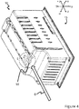
Figure 4 is perspective view of the inner liner in a cooling appliance according to the present invention, wherein the vicinity (E) around an exemplary guide formed thereon is emphasized. -
Figure 5 is detail from theFig.4 showing the vicinity (E) around the guide. - Referring to the figures summarized above, the present invention proposes a cooling appliance (100) comprising an inner liner (10) for defining at least one wall of a storage cabinet (15) of the cooling appliance, the inner liner being substantially surrounding by an outer shell (20), an insulation volume (30) between the inner liner (10) and the outer shell (20) for receiving an insulation material, and an inlet opening (40) on the outer shell (20) for introduction of an insulation material into the insulation volume (30) in a fluid state along an inlet direction (D).
- In the cooling appliance according to the present invention, the inner liner (10) is provided with a guide (50) which is located substantially at a projection of the inlet direction (D), said guide (50) having a shape and size adapted to guide and deflect the insulation material at said introduction.
- Such guide (50) provides a better solution to the problem of poor distribution of insulation material, when compared to simply increasing the distance of between the inner liner (10) and the outer shell (20) along a full height (h) of the cooling appliance (100), which would result in decreased volume of cooling compartment (15) and/or freezing compartment (16). The guide (50) allows a maximized volume in a compartment (i.e. the cooling compartment (15) or freezing compartment (16)) in vicinity of the inlet opening, without compromising the improved distribution of insulation material throughout the insulation volume (30).
- In case where the cooling appliance (100) is of top-freezer type (as exemplified in the
Fig.3 ), the present invention further eliminates sweating on outer shell portions around the freezing compartment (18), thanks to increased availability of uniformly distributed insulation material at the respective zones around the freezer (16) which are distal relative to the inlet opening (40). Accordingly, in an embodiment, the cooling appliance (100) can comprise a freezing compartment (16) at a distal portion of the cooling appliance (100) relative to the inlet opening (40), thereby the technical solution described in this section is obtained. - In an embodiment, the inlet opening (40) can be provided on an inlet portion (25) of the outer shell (20). In this case, the inlet portion (25) substantially corresponds to a plane (x/y) and the inlet direction (D) is substantially perpendicular to said plane (x/y). This provides facilitated alignment of the inlet direction (D) towards the guide (50), thereby further decreasing costs related to the production of the cooling appliance (100).
- The guide (50) can be a groove having a shape and size adapted to guide the insulation material away from the inlet opening (40). In other words, insulation material reaches far end of the insulation volume (30) compared to the inlet opening (40), when it is guided and deflected by the guide (50). In a further embodiment according to the present invention, the guide (50) can have a shape and size adapted to guide the insulation material substantially parallel to the inlet direction (D) and then at least partly deflect the insulation material to at least one side direction (-x/x) transverse to the inlet direction (D). This provides a further enhanced uniformity in distribution of the insulation material in directions substantially transverse to the inlet direction (D).
- The guide (50) is formed at an edge of the inner liner (10) that is substantially in a shape of a rectangle prism. The edge is the closest edge of the inner liner (10) to the inlet opening (40). The guide (50) faces the inlet opening (40), thus the insulation material introduced flows directly in the guide (50). The guide (50) lies along and/or parallel the inlet direction (D) on the inner liner (10). Then, the insulation material reaches an edge of the guide (50) and guided by the guide (50) towards the insulation volume (30) and the outer shell (20) by an inclined form of the guide (50). It may be inclined with a slope or a face with a radius.
- In a further embodiment of the cooling appliance according to the present invention, the guide (50) can have a shape and size adapted to guide the insulation material substantially parallel to the inlet direction (D) and then deflect the insulation material towards the outer shell (20). This results in that the insulation material in the form of liquid directed to the outer shell (20) impacts thereto at a distance from the inlet opening (40) along which the insulation material is guided; and scatters in the directions parallel to the outer shell (20) at such distance, thereby further enhancing the distribution of the insulation material.
- Considering that the cooling appliance (100) can have a height (h) in the inlet direction (D), and the guide can have a projection of a length (L) thereof substantially parallel to the inlet direction (D); the ratio (L:h) of the projection of length (L) of the guide to the height (h) on the inlet direction (D) is equal or less than 5:10 (e.i. 0.5). The ratio (h:L) values within this range is found to be optimal to both guiding the insulation material in the form of fluid to a sufficient distance from the inlet opening (40) to reach the distal end of the cooling appliance relative to the inlet opening. The range can further be between 0.05 and 0.06, which corresponds to further optimized values in the above described terms.
- The insulation volume (30) can be substantially filled with an insulating foam formed from the insulation material fed in fluid state. The insulating foam can comprise polyurethane. The improved distribution uniformity of the insulation material further avails improvement of optical properties of the cooling appliance, by avoidance of bumps on the outer shell or inner liner, thanks to elimination of the need to excessive use of the insulation material.
- Thus, the above-mentioned problems are solved, with the cooling appliance according to the present invention.
-
- 10
- inner liner
- 11
- inner liner of the prior art cooling appliance
- 15
- storage cabinet
- 16
- freezing compartment
- 17
- storage cabinet of the prior art cooling appliance
- 18
- freezing compartment of the prior art cooling appliance
- 20
- outer shell
- 21
- outer shell of the prior art cooling appliance
- 25
- inlet portion
- 30
- insulation volume
- 40
- inlet opening
- 41
- inlet opening of the prior art cooling appliance
- 50
- guide
- 100
- cooling appliance
- 101
- prior art cooling appliance
- D
- inlet direction
- D1
- inlet direction at the prior art cooling appliance
- h
- height of the cooling appliance
- L
- length of the guide in a direction substantially parallel to the height
Claims (9)
- A cooling appliance (100) comprising:- an inner liner (10) for defining at least one wall of a storage cabinet (15) of the cooling appliance, the inner liner being substantially surrounding by an outer shell (20),- an insulation volume (30) between the inner liner (10) and the outer shell (20) for receiving an insulation material,- and an inlet opening (40) on the outer shell (20) for introduction of an insulation material into the insulation volume (30) in a fluid state along an inlet direction (D); whereinthe inner liner (10) is provided with a guide (50) which is located substantially at a projection of the inlet direction (D), said guide (50) having a shape and size adapted to guide and deflect the insulation material at the introduction.
- The cooling appliance according to the claim 1, wherein the inlet opening (40) is provided on an inlet portion (25) of the outer shell (20), said inlet portion (25) substantially corresponding to a plane (x/y) and the inlet direction (D) is substantially perpendicular to said plane (x/y).
- The cooling appliance according to the claim 1 or 2, wherein the guide (50) is in the shape of a groove to guide the insulation material away from the inlet opening (40).
- The cooling appliance according to any one of the claims 1 to 3, wherein the guide (50) has a shape and size adapted to guide the insulation material substantially parallel to the inlet direction (D) and then at least partly deflect the insulation material to at least one side direction (-x/x) transverse to the inlet direction (D).
- The cooling appliance according to any one of the claims 1 to 4, wherein the guide (50) has a shape and size adapted to guide the insulation material substantially parallel to the inlet direction (D) and then deflect the insulation material towards the outer shell (20).
- The cooling appliance according to any one of the claims 1 to 5, said cooling appliance (100) having a height (h) in the inlet direction (D), and the guide having a projection of length (L) on the inlet direction (D); wherein the ratio (L:h) of the projection of length (L) of the guide to the height (h) on the inlet direction (D) is equal or less than 10:5.
- The cooling appliance according to any one of the claims 1 to 6, wherein the cooling appliance (100) comprises a freezing compartment (16) at a distal portion of the cooling appliance (100) relative to the inlet opening (40).
- The cooling appliance according to any one of the claims 1 to 7, wherein the insulation volume (30) is substantially filled with an insulating foam formed from the insulation material fed in fluid state.
- The cooling appliance according to the claim 8, wherein the insulating foam comprises polyurethane.
Priority Applications (1)
| Application Number | Priority Date | Filing Date | Title |
|---|---|---|---|
| PL18205962T PL3492849T3 (en) | 2017-11-30 | 2018-11-13 | A cooling appliance with a guide for insulation material |
Applications Claiming Priority (1)
| Application Number | Priority Date | Filing Date | Title |
|---|---|---|---|
| TR2017/19256A TR201719256A2 (en) | 2017-11-30 | 2017-11-30 | A cooling appliance with a guide for insulation material |
Publications (2)
| Publication Number | Publication Date |
|---|---|
| EP3492849A1 true EP3492849A1 (en) | 2019-06-05 |
| EP3492849B1 EP3492849B1 (en) | 2021-07-21 |
Family
ID=64308637
Family Applications (1)
| Application Number | Title | Priority Date | Filing Date |
|---|---|---|---|
| EP18205962.6A Active EP3492849B1 (en) | 2017-11-30 | 2018-11-13 | A cooling appliance with a guide for insulation material |
Country Status (3)
| Country | Link |
|---|---|
| EP (1) | EP3492849B1 (en) |
| PL (1) | PL3492849T3 (en) |
| TR (1) | TR201719256A2 (en) |
Cited By (1)
| Publication number | Priority date | Publication date | Assignee | Title |
|---|---|---|---|---|
| EP3971500A1 (en) * | 2020-09-18 | 2022-03-23 | Whirlpool Corporation | Walled structure for an appliance with wide sealable aperture for depositing insulation material within the walled structure |
Citations (4)
| Publication number | Priority date | Publication date | Assignee | Title |
|---|---|---|---|---|
| JPH0861837A (en) * | 1994-08-26 | 1996-03-08 | Toshiba Corp | Insulation box |
| DE4439349A1 (en) * | 1994-11-04 | 1996-05-09 | Aeg Hausgeraete Gmbh | Twin=wall refrigerator with insulant foam flow=guides between walls |
| JPH09303949A (en) * | 1996-05-17 | 1997-11-28 | Sanyo Electric Co Ltd | Heat insulating box |
| US20120266962A1 (en) | 2011-04-25 | 2012-10-25 | General Electric Company | Foam manifold for injection molding consumer appliance case, foamed-in case, and related method |
-
2017
- 2017-11-30 TR TR2017/19256A patent/TR201719256A2/en unknown
-
2018
- 2018-11-13 EP EP18205962.6A patent/EP3492849B1/en active Active
- 2018-11-13 PL PL18205962T patent/PL3492849T3/en unknown
Patent Citations (4)
| Publication number | Priority date | Publication date | Assignee | Title |
|---|---|---|---|---|
| JPH0861837A (en) * | 1994-08-26 | 1996-03-08 | Toshiba Corp | Insulation box |
| DE4439349A1 (en) * | 1994-11-04 | 1996-05-09 | Aeg Hausgeraete Gmbh | Twin=wall refrigerator with insulant foam flow=guides between walls |
| JPH09303949A (en) * | 1996-05-17 | 1997-11-28 | Sanyo Electric Co Ltd | Heat insulating box |
| US20120266962A1 (en) | 2011-04-25 | 2012-10-25 | General Electric Company | Foam manifold for injection molding consumer appliance case, foamed-in case, and related method |
Cited By (2)
| Publication number | Priority date | Publication date | Assignee | Title |
|---|---|---|---|---|
| EP3971500A1 (en) * | 2020-09-18 | 2022-03-23 | Whirlpool Corporation | Walled structure for an appliance with wide sealable aperture for depositing insulation material within the walled structure |
| US12078410B2 (en) | 2020-09-18 | 2024-09-03 | Whirlpool Corporation | Walled structure for an appliance with wide sealable aperture for depositing insulation material within the walled structure |
Also Published As
| Publication number | Publication date |
|---|---|
| EP3492849B1 (en) | 2021-07-21 |
| TR201719256A2 (en) | 2019-06-21 |
| PL3492849T3 (en) | 2021-11-22 |
Similar Documents
| Publication | Publication Date | Title |
|---|---|---|
| CN107606838B (en) | Refrigerator provided with ice maker and water supply unit | |
| KR100819085B1 (en) | Refrigerator | |
| CN105928300A (en) | Opening frame structure and refrigeration equipment | |
| CN205561391U (en) | Refrigerator tuber pipe and air -cooled refrigerator | |
| US20180073798A1 (en) | Refrigeration device with reinforced housing | |
| EP3492849B1 (en) | A cooling appliance with a guide for insulation material | |
| CN107002397A (en) | Storagetank, siphonic drainage system and effuser connecting elements | |
| CN205156478U (en) | Refrigerator and fix with screw post thereof | |
| US10739061B2 (en) | Temperature homogenizing container and refrigerator having same | |
| US11047608B2 (en) | Refrigerator | |
| US10821811B2 (en) | Refrigerant container | |
| CN104296460A (en) | Freezing chamber liner component for refrigerator and refrigerator with freezing chamber liner component | |
| KR102619014B1 (en) | Evaporator with double tube structure for ice making equipment | |
| CN104067077A (en) | Refrigerator assembly system and refrigerator | |
| JP5670722B2 (en) | Cooling storage | |
| EP4692684A1 (en) | Condenser | |
| US10890370B2 (en) | Cooling device having an air channel and a baffle | |
| CN215571477U (en) | Refrigerator | |
| CN103528305A (en) | Refrigerator | |
| CN112923625B (en) | A horizontal air-cooled freezer | |
| CN102589238A (en) | Ice scraper | |
| CN217737648U (en) | Box liner and refrigerator | |
| CN204177021U (en) | For refrigerator household freezer courage assembly and there is its refrigerator | |
| CN106766499A (en) | Refrigerator and its central sill | |
| CN110186234A (en) | Refrigeration equipment |
Legal Events
| Date | Code | Title | Description |
|---|---|---|---|
| PUAI | Public reference made under article 153(3) epc to a published international application that has entered the european phase |
Free format text: ORIGINAL CODE: 0009012 |
|
| STAA | Information on the status of an ep patent application or granted ep patent |
Free format text: STATUS: THE APPLICATION HAS BEEN PUBLISHED |
|
| AK | Designated contracting states |
Kind code of ref document: A1 Designated state(s): AL AT BE BG CH CY CZ DE DK EE ES FI FR GB GR HR HU IE IS IT LI LT LU LV MC MK MT NL NO PL PT RO RS SE SI SK SM TR |
|
| AX | Request for extension of the european patent |
Extension state: BA ME |
|
| STAA | Information on the status of an ep patent application or granted ep patent |
Free format text: STATUS: REQUEST FOR EXAMINATION WAS MADE |
|
| 17P | Request for examination filed |
Effective date: 20191205 |
|
| RBV | Designated contracting states (corrected) |
Designated state(s): AL AT BE BG CH CY CZ DE DK EE ES FI FR GB GR HR HU IE IS IT LI LT LU LV MC MK MT NL NO PL PT RO RS SE SI SK SM TR |
|
| GRAP | Despatch of communication of intention to grant a patent |
Free format text: ORIGINAL CODE: EPIDOSNIGR1 |
|
| STAA | Information on the status of an ep patent application or granted ep patent |
Free format text: STATUS: GRANT OF PATENT IS INTENDED |
|
| INTG | Intention to grant announced |
Effective date: 20210115 |
|
| GRAJ | Information related to disapproval of communication of intention to grant by the applicant or resumption of examination proceedings by the epo deleted |
Free format text: ORIGINAL CODE: EPIDOSDIGR1 |
|
| STAA | Information on the status of an ep patent application or granted ep patent |
Free format text: STATUS: REQUEST FOR EXAMINATION WAS MADE |
|
| GRAP | Despatch of communication of intention to grant a patent |
Free format text: ORIGINAL CODE: EPIDOSNIGR1 |
|
| STAA | Information on the status of an ep patent application or granted ep patent |
Free format text: STATUS: GRANT OF PATENT IS INTENDED |
|
| INTC | Intention to grant announced (deleted) | ||
| INTG | Intention to grant announced |
Effective date: 20210318 |
|
| GRAS | Grant fee paid |
Free format text: ORIGINAL CODE: EPIDOSNIGR3 |
|
| GRAA | (expected) grant |
Free format text: ORIGINAL CODE: 0009210 |
|
| STAA | Information on the status of an ep patent application or granted ep patent |
Free format text: STATUS: THE PATENT HAS BEEN GRANTED |
|
| AK | Designated contracting states |
Kind code of ref document: B1 Designated state(s): AL AT BE BG CH CY CZ DE DK EE ES FI FR GB GR HR HU IE IS IT LI LT LU LV MC MK MT NL NO PL PT RO RS SE SI SK SM TR |
|
| REG | Reference to a national code |
Ref country code: GB Ref legal event code: FG4D |
|
| REG | Reference to a national code |
Ref country code: CH Ref legal event code: EP |
|
| REG | Reference to a national code |
Ref country code: DE Ref legal event code: R096 Ref document number: 602018020360 Country of ref document: DE |
|
| REG | Reference to a national code |
Ref country code: AT Ref legal event code: REF Ref document number: 1412956 Country of ref document: AT Kind code of ref document: T Effective date: 20210815 |
|
| REG | Reference to a national code |
Ref country code: IE Ref legal event code: FG4D |
|
| REG | Reference to a national code |
Ref country code: LT Ref legal event code: MG9D |
|
| REG | Reference to a national code |
Ref country code: NL Ref legal event code: MP Effective date: 20210721 |
|
| REG | Reference to a national code |
Ref country code: AT Ref legal event code: MK05 Ref document number: 1412956 Country of ref document: AT Kind code of ref document: T Effective date: 20210721 |
|
| PG25 | Lapsed in a contracting state [announced via postgrant information from national office to epo] |
Ref country code: RS Free format text: LAPSE BECAUSE OF FAILURE TO SUBMIT A TRANSLATION OF THE DESCRIPTION OR TO PAY THE FEE WITHIN THE PRESCRIBED TIME-LIMIT Effective date: 20210721 Ref country code: SE Free format text: LAPSE BECAUSE OF FAILURE TO SUBMIT A TRANSLATION OF THE DESCRIPTION OR TO PAY THE FEE WITHIN THE PRESCRIBED TIME-LIMIT Effective date: 20210721 Ref country code: ES Free format text: LAPSE BECAUSE OF FAILURE TO SUBMIT A TRANSLATION OF THE DESCRIPTION OR TO PAY THE FEE WITHIN THE PRESCRIBED TIME-LIMIT Effective date: 20210721 Ref country code: FI Free format text: LAPSE BECAUSE OF FAILURE TO SUBMIT A TRANSLATION OF THE DESCRIPTION OR TO PAY THE FEE WITHIN THE PRESCRIBED TIME-LIMIT Effective date: 20210721 Ref country code: HR Free format text: LAPSE BECAUSE OF FAILURE TO SUBMIT A TRANSLATION OF THE DESCRIPTION OR TO PAY THE FEE WITHIN THE PRESCRIBED TIME-LIMIT Effective date: 20210721 Ref country code: BG Free format text: LAPSE BECAUSE OF FAILURE TO SUBMIT A TRANSLATION OF THE DESCRIPTION OR TO PAY THE FEE WITHIN THE PRESCRIBED TIME-LIMIT Effective date: 20211021 Ref country code: AT Free format text: LAPSE BECAUSE OF FAILURE TO SUBMIT A TRANSLATION OF THE DESCRIPTION OR TO PAY THE FEE WITHIN THE PRESCRIBED TIME-LIMIT Effective date: 20210721 Ref country code: LT Free format text: LAPSE BECAUSE OF FAILURE TO SUBMIT A TRANSLATION OF THE DESCRIPTION OR TO PAY THE FEE WITHIN THE PRESCRIBED TIME-LIMIT Effective date: 20210721 Ref country code: NO Free format text: LAPSE BECAUSE OF FAILURE TO SUBMIT A TRANSLATION OF THE DESCRIPTION OR TO PAY THE FEE WITHIN THE PRESCRIBED TIME-LIMIT Effective date: 20211021 Ref country code: PT Free format text: LAPSE BECAUSE OF FAILURE TO SUBMIT A TRANSLATION OF THE DESCRIPTION OR TO PAY THE FEE WITHIN THE PRESCRIBED TIME-LIMIT Effective date: 20211122 Ref country code: NL Free format text: LAPSE BECAUSE OF FAILURE TO SUBMIT A TRANSLATION OF THE DESCRIPTION OR TO PAY THE FEE WITHIN THE PRESCRIBED TIME-LIMIT Effective date: 20210721 |
|
| PG25 | Lapsed in a contracting state [announced via postgrant information from national office to epo] |
Ref country code: LV Free format text: LAPSE BECAUSE OF FAILURE TO SUBMIT A TRANSLATION OF THE DESCRIPTION OR TO PAY THE FEE WITHIN THE PRESCRIBED TIME-LIMIT Effective date: 20210721 Ref country code: GR Free format text: LAPSE BECAUSE OF FAILURE TO SUBMIT A TRANSLATION OF THE DESCRIPTION OR TO PAY THE FEE WITHIN THE PRESCRIBED TIME-LIMIT Effective date: 20211022 |
|
| REG | Reference to a national code |
Ref country code: DE Ref legal event code: R097 Ref document number: 602018020360 Country of ref document: DE |
|
| PG25 | Lapsed in a contracting state [announced via postgrant information from national office to epo] |
Ref country code: DK Free format text: LAPSE BECAUSE OF FAILURE TO SUBMIT A TRANSLATION OF THE DESCRIPTION OR TO PAY THE FEE WITHIN THE PRESCRIBED TIME-LIMIT Effective date: 20210721 |
|
| PLBE | No opposition filed within time limit |
Free format text: ORIGINAL CODE: 0009261 |
|
| STAA | Information on the status of an ep patent application or granted ep patent |
Free format text: STATUS: NO OPPOSITION FILED WITHIN TIME LIMIT |
|
| PG25 | Lapsed in a contracting state [announced via postgrant information from national office to epo] |
Ref country code: SM Free format text: LAPSE BECAUSE OF FAILURE TO SUBMIT A TRANSLATION OF THE DESCRIPTION OR TO PAY THE FEE WITHIN THE PRESCRIBED TIME-LIMIT Effective date: 20210721 Ref country code: SK Free format text: LAPSE BECAUSE OF FAILURE TO SUBMIT A TRANSLATION OF THE DESCRIPTION OR TO PAY THE FEE WITHIN THE PRESCRIBED TIME-LIMIT Effective date: 20210721 Ref country code: RO Free format text: LAPSE BECAUSE OF FAILURE TO SUBMIT A TRANSLATION OF THE DESCRIPTION OR TO PAY THE FEE WITHIN THE PRESCRIBED TIME-LIMIT Effective date: 20210721 Ref country code: EE Free format text: LAPSE BECAUSE OF FAILURE TO SUBMIT A TRANSLATION OF THE DESCRIPTION OR TO PAY THE FEE WITHIN THE PRESCRIBED TIME-LIMIT Effective date: 20210721 Ref country code: CZ Free format text: LAPSE BECAUSE OF FAILURE TO SUBMIT A TRANSLATION OF THE DESCRIPTION OR TO PAY THE FEE WITHIN THE PRESCRIBED TIME-LIMIT Effective date: 20210721 Ref country code: AL Free format text: LAPSE BECAUSE OF FAILURE TO SUBMIT A TRANSLATION OF THE DESCRIPTION OR TO PAY THE FEE WITHIN THE PRESCRIBED TIME-LIMIT Effective date: 20210721 |
|
| 26N | No opposition filed |
Effective date: 20220422 |
|
| PG25 | Lapsed in a contracting state [announced via postgrant information from national office to epo] |
Ref country code: MC Free format text: LAPSE BECAUSE OF FAILURE TO SUBMIT A TRANSLATION OF THE DESCRIPTION OR TO PAY THE FEE WITHIN THE PRESCRIBED TIME-LIMIT Effective date: 20210721 |
|
| REG | Reference to a national code |
Ref country code: CH Ref legal event code: PL |
|
| PG25 | Lapsed in a contracting state [announced via postgrant information from national office to epo] |
Ref country code: LU Free format text: LAPSE BECAUSE OF NON-PAYMENT OF DUE FEES Effective date: 20211113 Ref country code: BE Free format text: LAPSE BECAUSE OF NON-PAYMENT OF DUE FEES Effective date: 20211130 |
|
| REG | Reference to a national code |
Ref country code: BE Ref legal event code: MM Effective date: 20211130 |
|
| PG25 | Lapsed in a contracting state [announced via postgrant information from national office to epo] |
Ref country code: IE Free format text: LAPSE BECAUSE OF NON-PAYMENT OF DUE FEES Effective date: 20211113 |
|
| PG25 | Lapsed in a contracting state [announced via postgrant information from national office to epo] |
Ref country code: FR Free format text: LAPSE BECAUSE OF NON-PAYMENT OF DUE FEES Effective date: 20211130 |
|
| PGFP | Annual fee paid to national office [announced via postgrant information from national office to epo] |
Ref country code: IT Payment date: 20221130 Year of fee payment: 5 |
|
| PG25 | Lapsed in a contracting state [announced via postgrant information from national office to epo] |
Ref country code: CY Free format text: LAPSE BECAUSE OF FAILURE TO SUBMIT A TRANSLATION OF THE DESCRIPTION OR TO PAY THE FEE WITHIN THE PRESCRIBED TIME-LIMIT Effective date: 20210721 |
|
| GBPC | Gb: european patent ceased through non-payment of renewal fee |
Effective date: 20221113 |
|
| PG25 | Lapsed in a contracting state [announced via postgrant information from national office to epo] |
Ref country code: LI Free format text: LAPSE BECAUSE OF NON-PAYMENT OF DUE FEES Effective date: 20220701 Ref country code: HU Free format text: LAPSE BECAUSE OF FAILURE TO SUBMIT A TRANSLATION OF THE DESCRIPTION OR TO PAY THE FEE WITHIN THE PRESCRIBED TIME-LIMIT; INVALID AB INITIO Effective date: 20181113 Ref country code: CH Free format text: LAPSE BECAUSE OF NON-PAYMENT OF DUE FEES Effective date: 20220701 |
|
| PG25 | Lapsed in a contracting state [announced via postgrant information from national office to epo] |
Ref country code: GB Free format text: LAPSE BECAUSE OF NON-PAYMENT OF DUE FEES Effective date: 20221113 |
|
| PG25 | Lapsed in a contracting state [announced via postgrant information from national office to epo] |
Ref country code: MK Free format text: LAPSE BECAUSE OF FAILURE TO SUBMIT A TRANSLATION OF THE DESCRIPTION OR TO PAY THE FEE WITHIN THE PRESCRIBED TIME-LIMIT Effective date: 20210721 |
|
| PG25 | Lapsed in a contracting state [announced via postgrant information from national office to epo] |
Ref country code: MT Free format text: LAPSE BECAUSE OF FAILURE TO SUBMIT A TRANSLATION OF THE DESCRIPTION OR TO PAY THE FEE WITHIN THE PRESCRIBED TIME-LIMIT Effective date: 20210721 |
|
| PG25 | Lapsed in a contracting state [announced via postgrant information from national office to epo] |
Ref country code: IT Free format text: LAPSE BECAUSE OF NON-PAYMENT OF DUE FEES Effective date: 20231113 |
|
| PG25 | Lapsed in a contracting state [announced via postgrant information from national office to epo] |
Ref country code: IT Free format text: LAPSE BECAUSE OF NON-PAYMENT OF DUE FEES Effective date: 20231113 |
|
| PGFP | Annual fee paid to national office [announced via postgrant information from national office to epo] |
Ref country code: DE Payment date: 20251130 Year of fee payment: 8 |
|
| PGFP | Annual fee paid to national office [announced via postgrant information from national office to epo] |
Ref country code: TR Payment date: 20251110 Year of fee payment: 8 |
|
| PGFP | Annual fee paid to national office [announced via postgrant information from national office to epo] |
Ref country code: PL Payment date: 20251107 Year of fee payment: 8 |