EP3492722A1 - Coupling device for rotably coupling a shaft with a gearbox in a geared turbo fan engine - Google Patents
Coupling device for rotably coupling a shaft with a gearbox in a geared turbo fan engine Download PDFInfo
- Publication number
- EP3492722A1 EP3492722A1 EP18205169.8A EP18205169A EP3492722A1 EP 3492722 A1 EP3492722 A1 EP 3492722A1 EP 18205169 A EP18205169 A EP 18205169A EP 3492722 A1 EP3492722 A1 EP 3492722A1
- Authority
- EP
- European Patent Office
- Prior art keywords
- coupling device
- gearbox
- section
- cross
- profile
- Prior art date
- Legal status (The legal status is an assumption and is not a legal conclusion. Google has not performed a legal analysis and makes no representation as to the accuracy of the status listed.)
- Granted
Links
Images


Classifications
-
- F—MECHANICAL ENGINEERING; LIGHTING; HEATING; WEAPONS; BLASTING
- F16—ENGINEERING ELEMENTS AND UNITS; GENERAL MEASURES FOR PRODUCING AND MAINTAINING EFFECTIVE FUNCTIONING OF MACHINES OR INSTALLATIONS; THERMAL INSULATION IN GENERAL
- F16D—COUPLINGS FOR TRANSMITTING ROTATION; CLUTCHES; BRAKES
- F16D3/00—Yielding couplings, i.e. with means permitting movement between the connected parts during the drive
- F16D3/50—Yielding couplings, i.e. with means permitting movement between the connected parts during the drive with the coupling parts connected by one or more intermediate members
- F16D3/72—Yielding couplings, i.e. with means permitting movement between the connected parts during the drive with the coupling parts connected by one or more intermediate members with axially-spaced attachments to the coupling parts
- F16D3/74—Yielding couplings, i.e. with means permitting movement between the connected parts during the drive with the coupling parts connected by one or more intermediate members with axially-spaced attachments to the coupling parts the intermediate member or members being made of rubber or other rubber-like flexible material
-
- F—MECHANICAL ENGINEERING; LIGHTING; HEATING; WEAPONS; BLASTING
- F02—COMBUSTION ENGINES; HOT-GAS OR COMBUSTION-PRODUCT ENGINE PLANTS
- F02C—GAS-TURBINE PLANTS; AIR INTAKES FOR JET-PROPULSION PLANTS; CONTROLLING FUEL SUPPLY IN AIR-BREATHING JET-PROPULSION PLANTS
- F02C7/00—Features, components parts, details or accessories, not provided for in, or of interest apart form groups F02C1/00 - F02C6/00; Air intakes for jet-propulsion plants
- F02C7/36—Power transmission arrangements between the different shafts of the gas turbine plant, or between the gas-turbine plant and the power user
-
- F—MECHANICAL ENGINEERING; LIGHTING; HEATING; WEAPONS; BLASTING
- F05—INDEXING SCHEMES RELATING TO ENGINES OR PUMPS IN VARIOUS SUBCLASSES OF CLASSES F01-F04
- F05D—INDEXING SCHEME FOR ASPECTS RELATING TO NON-POSITIVE-DISPLACEMENT MACHINES OR ENGINES, GAS-TURBINES OR JET-PROPULSION PLANTS
- F05D2200/00—Mathematical features
- F05D2200/20—Special functions
- F05D2200/22—Power
-
- F—MECHANICAL ENGINEERING; LIGHTING; HEATING; WEAPONS; BLASTING
- F05—INDEXING SCHEMES RELATING TO ENGINES OR PUMPS IN VARIOUS SUBCLASSES OF CLASSES F01-F04
- F05D—INDEXING SCHEME FOR ASPECTS RELATING TO NON-POSITIVE-DISPLACEMENT MACHINES OR ENGINES, GAS-TURBINES OR JET-PROPULSION PLANTS
- F05D2200/00—Mathematical features
- F05D2200/20—Special functions
- F05D2200/23—Logarithm
-
- F—MECHANICAL ENGINEERING; LIGHTING; HEATING; WEAPONS; BLASTING
- F05—INDEXING SCHEMES RELATING TO ENGINES OR PUMPS IN VARIOUS SUBCLASSES OF CLASSES F01-F04
- F05D—INDEXING SCHEME FOR ASPECTS RELATING TO NON-POSITIVE-DISPLACEMENT MACHINES OR ENGINES, GAS-TURBINES OR JET-PROPULSION PLANTS
- F05D2250/00—Geometry
- F05D2250/70—Shape
- F05D2250/71—Shape curved
-
- F—MECHANICAL ENGINEERING; LIGHTING; HEATING; WEAPONS; BLASTING
- F05—INDEXING SCHEMES RELATING TO ENGINES OR PUMPS IN VARIOUS SUBCLASSES OF CLASSES F01-F04
- F05D—INDEXING SCHEME FOR ASPECTS RELATING TO NON-POSITIVE-DISPLACEMENT MACHINES OR ENGINES, GAS-TURBINES OR JET-PROPULSION PLANTS
- F05D2260/00—Function
- F05D2260/40—Transmission of power
-
- F—MECHANICAL ENGINEERING; LIGHTING; HEATING; WEAPONS; BLASTING
- F05—INDEXING SCHEMES RELATING TO ENGINES OR PUMPS IN VARIOUS SUBCLASSES OF CLASSES F01-F04
- F05D—INDEXING SCHEME FOR ASPECTS RELATING TO NON-POSITIVE-DISPLACEMENT MACHINES OR ENGINES, GAS-TURBINES OR JET-PROPULSION PLANTS
- F05D2260/00—Function
- F05D2260/40—Transmission of power
- F05D2260/403—Transmission of power through the shape of the drive components
- F05D2260/4031—Transmission of power through the shape of the drive components as in toothed gearing
- F05D2260/40311—Transmission of power through the shape of the drive components as in toothed gearing of the epicyclical, planetary or differential type
-
- F—MECHANICAL ENGINEERING; LIGHTING; HEATING; WEAPONS; BLASTING
- F05—INDEXING SCHEMES RELATING TO ENGINES OR PUMPS IN VARIOUS SUBCLASSES OF CLASSES F01-F04
- F05D—INDEXING SCHEME FOR ASPECTS RELATING TO NON-POSITIVE-DISPLACEMENT MACHINES OR ENGINES, GAS-TURBINES OR JET-PROPULSION PLANTS
- F05D2260/00—Function
- F05D2260/94—Functionality given by mechanical stress related aspects such as low cycle fatigue [LCF] of high cycle fatigue [HCF]
-
- F—MECHANICAL ENGINEERING; LIGHTING; HEATING; WEAPONS; BLASTING
- F16—ENGINEERING ELEMENTS AND UNITS; GENERAL MEASURES FOR PRODUCING AND MAINTAINING EFFECTIVE FUNCTIONING OF MACHINES OR INSTALLATIONS; THERMAL INSULATION IN GENERAL
- F16D—COUPLINGS FOR TRANSMITTING ROTATION; CLUTCHES; BRAKES
- F16D1/00—Couplings for rigidly connecting two coaxial shafts or other movable machine elements
- F16D1/10—Quick-acting couplings in which the parts are connected by simply bringing them together axially
- F16D2001/103—Quick-acting couplings in which the parts are connected by simply bringing them together axially the torque is transmitted via splined connections
Definitions
- the coupling device comprises a plurality of oil holes symmetrically positioned around a circumference of the coupling device, in particular positioned at the maximum radius.
- the cross-section is thickened around the oil holes.
- the logarithmic profile L of the cross-section approaches asymptotically a line Asym which is in this embodiment parallel to the rotational axis 11. That means that at the second end B the median line M is almost parallel to the rotational axes.
Landscapes
- Engineering & Computer Science (AREA)
- General Engineering & Computer Science (AREA)
- Mechanical Engineering (AREA)
- Chemical & Material Sciences (AREA)
- Combustion & Propulsion (AREA)
- Structures Of Non-Positive Displacement Pumps (AREA)
- General Details Of Gearings (AREA)
Abstract
Description
- The invention relates to a system for a coupling device for rotably coupling a shaft with a gearbox in a geared turbo fan engine with the features of
claim 1. - Geared turbo fan engines for aircrafts comprise a gearbox which transforms the high rotational speed of a turbine section to a lower rotational speed of a propulsive fan in the turbo fan engine. By allowing different rotational speeds between the turbine section and the propulsive fan, the overall efficiency of the aircraft engine is improved.
- The gearbox has to handle considerable mechanical loads, in particular torque loads, so an effective torque transmission from or to the gearbox within the aircraft engine is required.
- Couplings for geared turbo fan engines are e.g. described in
EP 3 144 487 A1 - This issue is addressed by the coupling device with the features of
claim 1. - The coupling device rotably couples a shaft with a gearbox in the geared turbo fan aircraft engine. The coupling device comprises a connection to the shaft at a first end and a connection to the gearbox at a second end, the first and the second ends being axially separated from each other. Between the first and second end at least one curved shape extending from the gearbox radially inwards to the shaft is located; i.e. the coupling device can have other sections which are differently formed, but at least one curved shape. This at least one curved shaped comprises at least one cross-section in the axial direction of the engine with a logarithmic profile or a power profile. The logarithmic profile can be mathematically described by a logarithmic or exponential functional relationship.
- The at least one curved shape of a coupling device is considered to have a logarithmic profile if a logarithmic curve of the form

- The curved shape of a coupling device is considered to have a power profile to which a power curve of the form

- Having at least one logarithmic profile section or at least one power profile in the coupling device, it provides a very high ratio of torsional stiffness over the lateral one at lowest weight penalty, subject e.g. to stress constraints.
- In one embodiment the logarithmic profile or the power profile applies to a median line of the coupling device, a cross-section of an inner surface of the coupling device and / or a cross-section of an outer surface of the coupling device. This means that the logarithmic profile or power profile can be applied to different lines or shapes of the coupling device. In one embodiment of the coupling device the logarithmic profile or the power profile approaches asymptotically a line parallel to the rotational axis of the geared turbo fan engine or the logarithmic profile or the power profile approaches asymptotically a line perpendicular to the rotational axis of the geared turbo fan engine. In particular, the asymptotic approach can be at a torque input or torque output of the gearbox (i.e. the second end of the coupling device), in particular a carrier for planetary gears or a ring gear mount of the gearbox. In this case the torque input or output are asymptotically approached, i.e. the tangents towards the gearbox gets flatter. It is also possible, that the asymptotic approach is not at the second end of the coupling device, e.g. at one point between the first and the second end.
- In a further embodiment of the coupling device the radius measured from the rotational axis to the coupling device is constant over at least one axial section, in particular, at the torque input or torque output of the gearbox, in particular a carrier for planetary gears or a ring gear mount of the gearbox. This means that the coupling device comprises the at least one logarithmically or power shaped curved section and a tubular section with a constant radius. The tubular part can e.g. be used to save space within the engine close to the gearbox.
- In another embodiment the coupling device has a cross-sectional thickness that varies at least along some section between the first end and the second end. In particular, the thickness of the cross-section decreases at least in parts from the first end and the second end, in particular, it decreases monotonously. In this particular embodiment the thickness is largest in the connection point to the shaft and thinnest at the connection to the gearbox. In one particular embodiment the thickness varies logarithmically or according to a power law along the curved shaped part.
- It is possible that the thickness of the cross-section varies with the same functional relationship as the curved shape.
- It is possible that in one embodiment of the coupling device the cross-section comprises a maximal radius between the first end and the second end. The radius at the torque input or torque output of the gearbox is smaller than the maximal radius.
- It is also possible that the coupling device comprises a plurality of oil holes symmetrically positioned around a circumference of the coupling device, in particular positioned at the maximum radius. In this case it is possible, that the cross-section is thickened around the oil holes.
- Typically, an embodiment of a coupling device can have a maximal radius between 50 and 200 mm. The axial extension of the logarithmic profile or the power profile can be between 40 and 200 mm.
- The connection between the coupling device with the shaft can e.g. be made with a spline connection.
- Embodiments of the invention are shown in the figures, where
- Fig. 1
- shows a schematic drawing of a geared turbo fan engine according to the prior art;
- Fig. 2
- shows a cross-sectional view of an embodiment of a coupling between a fan shaft and a gearbox;
- Fig. 2A
- shows a variation of the embodiment shown in
Fig.2 ; - Fig. 2B
- shows a variation of the embodiment shown in
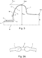
Fig. 2 ; - Fig. 3
- shows a cross-sectional view of a further embodiment of a coupling between a fan shaft and a gearbox;
- Fig. 3A
- shows a cross-section of a detail of an oil hole in the embodiment shown in
Fig. 3 . - With reference to
Fig. 1 , a geared turbo fan engine for an aircraft is generally indicated at 10, having a principal androtational axis 11. Theengine 10 comprises, in axial flow series, anair intake 12, a propulsive fan 13 (could be more than one stage), agearbox 14, anintermediate pressure compressor 15, a high-pressure compressor 16, acombustion equipment 17, a high-pressure turbine 18, an intermediate-pressure turbine 19 and anexhaust nozzle 20. Afan casing 21 generally surrounds theengine 10 and defines theintake 12. - The geared
turbo fan engine 10 works in the conventional manner so that air entering theintake 12 is accelerated by thepropulsive fan 13 to produce two air flows: a first air flow into theintermediate pressure compressor 15 and a second air flow which passes through abypass duct 22 to provide propulsive thrust. Theintermediate pressure compressor 15 compresses the air flow directed into it before delivering that air to thehigh pressure compressor 16 where further compression takes place. - The compressed air exhausted from the high-
pressure compressor 16 is directed into thecombustion equipment 17 where it is mixed with fuel and the mixture is combusted. The resultant hot combustion products then expand through, and thereby drive thehigh pressure turbine 18 and intermediate pressure turbine 19 (i.e. turbine sections) before being exhausted through thenozzle 20 to provide additional propulsive thrust. Thehigh pressure turbine 18 and theintermediate pressure turbine 19, respectively, drive thehigh pressure compressor 16 and theintermediate pressure compressor 15, each by suitable interconnecting shaft assembly. - An
intermediate pressure shaft 101 also drives thepropulsive fan 13 via thegearbox 14. Thegearbox 14 is a reduction gearbox in that it gears down the rate of rotation of thepropulsive fan 13 by comparison with theintermediate pressure compressor 15 andintermediate pressure turbine 19. - The
gearbox 14 is an epicyclic planetary gearbox having a static ring gear mount 105 (e.g. here two parallel ring gears), rotating and orbitingplanet gears 103 supported by aplanet carrier 104 and a rotatingsun gear 102. In the embodiment shown the torque output of thegearbox 14 is through thecarrier 104, the torque input via thesun gear 102. In principle,other gearbox 14 designs can be used, e.g. the torque output can be via a rotatablering gear mount 105. - The embodiment shown in
Fig. 1 has a specific shaft arrangement which is understood not to be limiting. The embodiments described in the following can also work with a 2- or 3-shaft arrangement. - In
Fig. 1 the coupling of the at least onering gear 1 within afront casing 4 of the gearedturbo fan engine 10 is only shown schematically. - In the following
embodiments coupling devices 1 are shown coupling thegearbox 14 with a shaft. InFig. 2 and3 embodiments are shown in which the torque output of the gearbox 14 (here via thecarrier 104 of the planetary gears 103) is coupled to ashaft 4 driving thepropulsive fan 4. Thecoupling device 1 transfers torque from thegearbox 14 to thepropulsive fan 13. - In
Fig. 2 thecoupling device 1 is connected through aspline connection 3 to thefan shaft 4 which drives the propulsive fan 13 (not shown inFig. 2 ). The connection tofan shaft 4 defines the first end A of thecoupling device 1. The second end B is at the torque output of thegearbox 14, i.e. at thecarrier 104. - The first and the second ends A, B are axially spaced apart along the axis of the geared turbo fan engine 10 (not shown in
Fig. 2 ). - The
coupling device 1 shown inFig. 2 comprises one curved shape between the first end A and the second end B extending from the gearbox 14 (i.e. thecarrier 104 inFig. 2 ) radially inwards towards theshaft 4. This means the coupling device arcs inwards form the torque output of thegearbox 14 towards theshaft 4. The maximum radius Rmax of this embodiment is at the torque output of thegearbox 14, i.e. the second end B. The minimum radius is at the first end A at the shaft A. In other embodiments (e.g. shown inFig. 2A or3 ) the shape of thecoupling device 1 can be different or more complex and can also comprise more than one curved shapes. - The curved shape of the
coupling device 1 comprises one cross-section in the axial direction of the engine with a logarithmic profile L. In the embodiment shown the logarithmic profile L extends almost from the first end A to the second B. In alternative embodiments the logarithmic profile does only extend over a part of the curved shape. - In the embodiment shown it is assumed that the median line M follows the logarithmic profile L. It is possible that the inner surface I or the outer surface O follow the logarithmic profile L. Also combinations, e.g. inner surface I, median line M and the outer surface O have a logarithmic shape L, but with slightly different curvature since the cross-sectional thickness T of the
coupling device 1 is highest at the first end A, and smallest at the second end B. - For sake of simplicity the logarithmic profile L of the median line M is discussed in the following.
- The logarithmic profile L of the cross-section approaches asymptotically a line Asym which is in this embodiment parallel to the
rotational axis 11. That means that at the second end B the median line M is almost parallel to the rotational axes. - It is understood that a shape of a coupling device is considered to have a logarithmic profile if a logarithmic curve

Fig. 2 ). - The logarithmic relationship can be described as a different functional relationship. One coordinate system is chosen here, where the origin is placed at the first end A.
- The axial coordinate x extends towards the back of the geared
turbofan engine 10, i.e. away from thepropulsive fan 14. The coordinate r(x) extends from the first end A radially outwards. The logarithmic profile L as r(x) - given these coordinates - follows the following exponential equation (A1, A2 as arbitrary constants)
- As x increases from the first end A to the right in
Fig. 2 , the logarithmic profile L (as a function of x) approaches Rmax at the second end B, i.e. it approaches the line Asym parallel to therotational axis 11. It should be noted that the maximal radius of thecoupling device 1 is Rmax (as shown inFig. 2 ) plus the offset of the origin of the coordinate system from therotational axis 11. This equation given above is to be understood as model equation for the logarithmic profile L only. The realization of thecoupling device 1 might show some deviation from the exact mathematical logarithmic shape. - It is also understood that the mathematical representation of the logarithmic profile L can be made with an exponential equation or a logarithmic equation, depending on the coordinate system chosen. In the embodiment of
Fig. 2 the logarithmic profile L approaches the second end B asymptotically. - In a further embodiment not depicted here, the curved shape can follow a power law:

- This means that a curve with this profile can be fitted to at least a section of the median line M, the inner surface I and / or the outer surface shape with a regression coefficient of r2 = 0,9 or more. A1, A2 are the model parameter of the power model.
- The
coupling device 1 forms in the embodiment ofFig. 2 a flexible output coupling with at least one section with a logarithmic profile. It has been found that this maximizes the lateral flexibility and the rotational (torsional) stiffness - usually mutually contradictory requirements - at the lowest weight penalty and under a given allowable stress constraint. One possible objective function which is satisfied by embodiments described herein is the ratio
- The
coupling device 1 with the logarithmic profile L also has good buckling and stress / fatigue properties. In fact, the logarithmic shape and variable thickness of thecoupling device 1 make the latter optimized for stress vs. weight. - In
Fig. 2A an alternative embodiment of the one described inFig. 2 is shown. Reference can be made to the respective description. - In
Fig. 2A the curvature of the logarithmic shape L is different, i.e. the asymptote Asym' is perpendicular to therotational axis 11. The functional relationship for the logarithmic profile L in this case would be (given a suitable coordinate system)
- If x approaches the axial position of Rmax, the curvature asymptotically approaches the line Asym' perpendicular to the
rotational axis 11. In embodiments ofFig. 2 and2A the asymptotes are approached at point B, i.e. thecarrier 104. - In
Fig. 2B a further embodiment is shown, in which the logarithmic shape L approaches the Point A, i.e. thespline connection 3 asymptotically with the Asymptote Asym" being parallel to the rotational axis. The functional relationship for the logarithmic profile L in this case would be (given a suitable coordinate system)
- In
Fig. 3 a different embodiment ofcoupling device 1 is shown. The design context of thecoupling device 1 is the same as in the embodiment shown inFig. 2 so that reference can be made to the relevant description. - The embodiment shown in
Fig. 2 , comprises a logarithmic profile L starting at the first end A (i.e. at the connection of thecoupling device 1 with the fan shaft 4) which approaches the point Max on thecoupling device 1 which is the point of the maximum radius Rmax. The shape of the logarithmic profile L in the one section of thecoupling device 1 can be determined as described in connection with the previous embodiment. - The second end B of the
coupling device 1 is coupled to thecarrier 104 of thegearbox 14. The radius R measured from therotational axis 11 to thecoupling device 1 here is constant in a section extending from the second end B towards the front of the gearedturbo fan engine 10. The radius R is considerably smaller than RMax in the section with the constant radius R. With this design some special constraints in the vicinity of thegearbox 14 can be addressed. - Typically, an embodiment of a
coupling device 1 can have a maximal radius Rmax between 50 and 200 mm, in particular 100 mm. In the embodiment ofFig. 2 this would be the radius at the second end B. In the embodiment ofFig. 3 this would be the maximal Radius at Point Max. The axial extension of the logarithmic profile L or the power profile can be between 40 and 200 mm (embodiment ofFig 2 ,2A : between first and second ends A, B; embodiment ofFig. 3 : between first end and point Max). These values are typical for several geared turbofan engines. - The curved shape of the embodiment shown in
Fig. 3 could also be in the form of the shape shown inFig. 2A . - The
coupling device 1, of which cross-sections are shown inFig. 2 ,2A and3 , is a body of revolution since it extends circumferentially around therotational axis 11. Within the cavity inside thecoupling device 1, oil is present to lubricate thespline connection 3, theshafts 4, bearings (not shown) and other units within thecoupling device 1. - To allow scavenging the oil from the inside,
oil holes 2 are positioned e.g. at the position of the maximal radius Rmax in the embodiment ofFig. 3 . - The oil holes 2 are positioned symmetrically around the circumference of the
coupling device 1. Since the oil holes structurally weaken the coupling device locally, the thickness of thecoupling device 1 is locally increased as e.g. shown inFig. 3A . - In principle, it is also possible to locate the oil holes in other sections of the coupling device.
-
- 1
- coupling device
- 2
- oil holes
- 3
- spline connection to shaft
- 4
- fan shaft
- 10
- geared turbo fan engine
- 11
- principal rotational axis
- 12
- air intake
- 13
- propulsive fan
- 14
- gearbox, power gearbox
- 15
- intermediate pressure compressor
- 16
- high-pressure compressor
- 17
- combustion equipment
- 18
- high-pressure turbine
- 19
- intermediate-pressure turbine
- 20
- exhaust nozzle
- 21
- fan casing
- 22
- by-pass duct
- 101
- intermediate pressure shaft
- 102
- sun gear
- 103
- planetary gears
- 104
- carrier of the planetary gears
- 105
- ring gear mount
- A
- first end of coupling device
- A1
- model parameter
- A2
- model parameter
- Asym
- asymptote of logarithmic profile
- Asym'
- asymptote of logarithmic profile
- Asym"
- asymptote of logarithmic profile
- B
- second end of coupling device
- I
- inner surface of coupling device
- L
- logarithmic profile
- M
- median line of coupling device
- Max
- point on the coupling device at Rmax
- O
- outer surface of coupling device
- r
- radial coordinate in a coordinate system
- R
- radius
- Rmax
- maximal radius
- T
- thickness of cross-section of the coupling device
- X
- axial coordinate in a coordinate system
Claims (15)
- Coupling device (1) for rotably coupling a shaft (4) with a gearbox (14) in a geared turbo fan aircraft engine (10), wherein the coupling device (1) comprises a connection to the shaft (4) at a first end (A) and a connection to the gearbox (14) at a second end (B), the first and the second ends (A, B) being axially separated and at least one curved shape between the first end (A) and the second end (B) extending from the gearbox (14) radially inwards to the shaft (4) and the at least one curved shape comprising at least one cross-section in the axial direction of the engine (1) with a logarithmic profile (L) or a power profile, wherein
the at least one curved shape of a coupling device is considered to have a logarithmic profile (L) to which a logarithmic curve
can be fitted to at least a section of the median line (M), the inner surface shape (I) and / or the outer surface (O) shape with a regression coefficient of r2 = 0,9 or more,
or
the at least one curved shape of a coupling device is considered to have a power profile to which a power curve
can be fitted to at least a section of the median line (M), the inner surface shape (I) and / or the outer surface (O) shape with a regression coefficient of r2 = 0,9 or more. - Coupling device according to claim 1, wherein the logarithmic profile (L) or the power profile applies to a median line (M) of the coupling device (1), a cross-section of an inner surface (I) of the coupling device and / or a cross-section of an outer surface (O) of the coupling device (1).
- Coupling device according to claim 1 or 2, wherein the logarithmic profile (L) or the power profile approaches asymptotically a line (Asym) parallel to the rotational axis (11) or the logarithmic profile (L) approaches asymptotically a line (Asym') perpendicular to the rotational axis (11), in particular at a torque input or torque output of the gearbox (14), in particular a carrier (104) for planetary gears (103) or a ring gear mount of the gearbox (14).
- Coupling device according to at least one of the preceding claims, wherein the radius (r) measured from the rotational axis (11) to the coupling device (1) is constant over at least one axial section, in particular, at the torque input or torque output of the gearbox (14), in particular, a carrier (104) for planetary gears (103) or a ring gear mount of the gearbox (14).
- Coupling device according to at least one of the preceding claims, wherein the thickness (T) of the cross-section of the coupling device (1) varies at least along some section between the first end (A) and the second end (B).
- Coupling device according to claim 5, wherein the thickness (T) of the cross-section decreases at least in parts from the first end (A) and the second end (B), in particular, it decreases monotonously.
- Coupling device according to claim 5 or 6, wherein the thickness (T) of the cross-section varies logarithmically or according to a power law at least in parts from the first end (A) and the second end (B).
- Coupling device according to at least one of the claims 5 to 7, wherein the thickness (T) of the cross-section varies with the same functional relationship as the curved shape.
- Coupling device according to at least one of the preceding claims, wherein the cross-section comprises a maximal radius (Rmax) between the first end (A) and the second end (B), wherein in particular radius (R) at the torque input or torque output of the gearbox (14) is smaller than the maximal radius (Rmax).
- Coupling device according to at least one of the preceding claims, with a plurality of oil holes (2) symmetrically positioned around a circumference of the coupling device (1), in particular positioned at the maximum radius (Rmax).
- Coupling device according to claim 10, wherein the cross-section is thickened around the oil holes (2).
- Coupling device according to at least one of the preceding claims, wherein the maximal radius (Rmax) is between 50 and 200 mm, in particular 100 mm.
- Coupling device according to at least one of the preceding claims, wherein the axial extension of the logarithmic profile (L) is between 40 and 200 mm.
- Coupling device according to at least one of the preceding claims with a spline connection (3) to the shaft (4).
- Geared turbo fan engine with at least one coupling device according to at least one of the claims 1 to 14.
Applications Claiming Priority (1)
| Application Number | Priority Date | Filing Date | Title |
|---|---|---|---|
| DE102017128490 | 2017-11-30 |
Publications (2)
| Publication Number | Publication Date |
|---|---|
| EP3492722A1 true EP3492722A1 (en) | 2019-06-05 |
| EP3492722B1 EP3492722B1 (en) | 2021-08-18 |
Family
ID=64267665
Family Applications (1)
| Application Number | Title | Priority Date | Filing Date |
|---|---|---|---|
| EP18205169.8A Active EP3492722B1 (en) | 2017-11-30 | 2018-11-08 | Coupling device for rotably coupling a shaft with a gearbox in a geared turbo fan engine |
Country Status (2)
| Country | Link |
|---|---|
| US (1) | US11542989B2 (en) |
| EP (1) | EP3492722B1 (en) |
Families Citing this family (1)
| Publication number | Priority date | Publication date | Assignee | Title |
|---|---|---|---|---|
| CN111027144B (en) * | 2019-12-24 | 2023-09-22 | 中国航空工业集团公司西安飞机设计研究所 | A stiffness-based wing box selection method |
Citations (3)
| Publication number | Priority date | Publication date | Assignee | Title |
|---|---|---|---|---|
| US20090298640A1 (en) * | 2006-03-22 | 2009-12-03 | United Technologies Corporation | Integral sun gear coupling |
| US20120077607A1 (en) * | 2010-09-27 | 2012-03-29 | Eurocopter | Flexible coupling means |
| EP3002434A1 (en) * | 2014-10-03 | 2016-04-06 | Rolls-Royce plc | Geared architecture for a gas turbine with squeeze film damper |
Family Cites Families (21)
| Publication number | Priority date | Publication date | Assignee | Title |
|---|---|---|---|---|
| US3024628A (en) * | 1961-02-06 | 1962-03-13 | Dodge Mfg Corp | Flexible coupling |
| DE1525341A1 (en) * | 1966-03-07 | 1969-07-10 | Colmant Cuvelier | Flexible coupling for the transmission of movements between two shafts |
| DE2255680B2 (en) * | 1972-11-14 | 1978-10-05 | Vulkan Kupplungs- Und Getriebebau, Bernhard Hackforth Gmbh & Co Kg, 4690 Herne | Compliant shaft coupling |
| DE2438088C3 (en) * | 1974-08-08 | 1988-03-24 | BBC Brown Boveri AG, 6800 Mannheim | Power transmission device between hollow shaft and drive wheel of an electric rail vehicle |
| US4107950A (en) * | 1977-05-26 | 1978-08-22 | Ernest Wildhaber | Flexible-disk coupling |
| US4411634A (en) * | 1980-11-10 | 1983-10-25 | The Bendix Corporation | Flexible coupling having molded plastic flexible diaphragms |
| DE3302777A1 (en) * | 1983-01-28 | 1984-08-02 | Phoenix Ag, 2100 Hamburg | Process for manufacturing a filament cage of frustoconical shape for reinforcing inlay of couplings |
| US5000722A (en) * | 1990-03-26 | 1991-03-19 | Kop-Flex, Inc. | Coupling member for rotatable shafts |
| DE4215540C2 (en) * | 1992-05-12 | 1994-02-17 | Kirschey Centa Antriebe | Torsionally flexible coupling |
| US5588917A (en) * | 1994-11-14 | 1996-12-31 | Kop-Flex, Inc. | Coupling with dual torque transmission paths |
| US5899813A (en) * | 1996-06-21 | 1999-05-04 | Lucas Aerospace Power Transmission | Non-welded joint using a polygon |
| US5961244A (en) * | 1997-10-10 | 1999-10-05 | The Atlantic Group, Inc. | Expansion-joint system and belt |
| US20030157987A1 (en) * | 2000-10-26 | 2003-08-21 | Kop Flex, Inc. | Shaft couplings with bonded flexible elements |
| US7493754B2 (en) | 2005-10-19 | 2009-02-24 | General Electric Company | Gas turbine engine assembly and methods of assembling same |
| US7544130B2 (en) * | 2006-09-13 | 2009-06-09 | Reliance Electric Technologies, Llc | Flexible shaft coupling system with antirotational features |
| US8591345B2 (en) * | 2011-09-09 | 2013-11-26 | Goodrich Corporation | Flexible diaphragm coupling for axial force loading |
| US8900090B2 (en) | 2012-11-30 | 2014-12-02 | United Technologies Corporation | Geared architecture gas turbine engine with improved lubrication and misalignment tolerant roller bearing system |
| EP3002475B1 (en) * | 2014-09-30 | 2019-03-06 | Ellergon Antriebstechnik GmbH | Device for absorbing struture-borne sound |
| US11067005B2 (en) | 2015-02-03 | 2021-07-20 | Raytheon Technologies Corporation | Fan drive gear system |
| GB201516571D0 (en) | 2015-09-18 | 2015-11-04 | Rolls Royce Plc | A Coupling for a Geared Turbo Fan |
| GB2544036A (en) | 2015-09-30 | 2017-05-10 | Rolls Royce Deutschland Ltd & Co Kg | A planet carrier assembly for an epicyclic gearbox |
-
2018
- 2018-10-18 US US16/164,207 patent/US11542989B2/en active Active
- 2018-11-08 EP EP18205169.8A patent/EP3492722B1/en active Active
Patent Citations (3)
| Publication number | Priority date | Publication date | Assignee | Title |
|---|---|---|---|---|
| US20090298640A1 (en) * | 2006-03-22 | 2009-12-03 | United Technologies Corporation | Integral sun gear coupling |
| US20120077607A1 (en) * | 2010-09-27 | 2012-03-29 | Eurocopter | Flexible coupling means |
| EP3002434A1 (en) * | 2014-10-03 | 2016-04-06 | Rolls-Royce plc | Geared architecture for a gas turbine with squeeze film damper |
Also Published As
| Publication number | Publication date |
|---|---|
| US11542989B2 (en) | 2023-01-03 |
| US20190162240A1 (en) | 2019-05-30 |
| EP3492722B1 (en) | 2021-08-18 |
Similar Documents
| Publication | Publication Date | Title |
|---|---|---|
| US12158111B2 (en) | Planetary gearbox for gas turbine engine | |
| US11300007B2 (en) | Planetary gearbox having compliant journal bearings | |
| US9021778B2 (en) | Differential gear system with carrier drive | |
| US6964155B2 (en) | Turbofan engine comprising an spicyclic transmission having bearing journals | |
| US7493753B2 (en) | Gas turbine engine assembly and methods of assembling same | |
| EP2949881B1 (en) | Geared architecture for high speed and small volume fan drive turbine | |
| US11022044B1 (en) | Geared gas turbine engine | |
| EP2925982B1 (en) | Geared architecture gas turbine engine with improved lubrication and misalignment tolerant roller bearing system | |
| US10859001B1 (en) | Gas turbine engine having flight cycle ratio | |
| EP3306116B1 (en) | Geared turbofan engine and sun shaft for driving sun gear of planetary gearbox | |
| EP3270009A1 (en) | A geared gas turbine engine and a gearbox | |
| EP3296524B1 (en) | Gas turbine engine with a geared turbofan arrangement | |
| US12221929B2 (en) | High power epicyclic gearbox and operation thereof | |
| EP3109451A1 (en) | Gear system for high bypass ratio geared turbofan engine | |
| US12276228B2 (en) | Planet gear clearances in epicyclic gearboxes | |
| EP3492722B1 (en) | Coupling device for rotably coupling a shaft with a gearbox in a geared turbo fan engine | |
| US12565860B2 (en) | Geared gas turbine engine | |
| CN113819197A (en) | System and method for reducing edge contact stress concentrations in press fits | |
| EP3093512B1 (en) | A bearing shaft | |
| EP4306787A1 (en) | Gearbox assembly | |
| CN112610684B (en) | Bearing spring for epicyclic gear system housing assembly |
Legal Events
| Date | Code | Title | Description |
|---|---|---|---|
| PUAI | Public reference made under article 153(3) epc to a published international application that has entered the european phase |
Free format text: ORIGINAL CODE: 0009012 |
|
| STAA | Information on the status of an ep patent application or granted ep patent |
Free format text: STATUS: THE APPLICATION HAS BEEN PUBLISHED |
|
| AK | Designated contracting states |
Kind code of ref document: A1 Designated state(s): AL AT BE BG CH CY CZ DE DK EE ES FI FR GB GR HR HU IE IS IT LI LT LU LV MC MK MT NL NO PL PT RO RS SE SI SK SM TR |
|
| AX | Request for extension of the european patent |
Extension state: BA ME |
|
| STAA | Information on the status of an ep patent application or granted ep patent |
Free format text: STATUS: REQUEST FOR EXAMINATION WAS MADE |
|
| 17P | Request for examination filed |
Effective date: 20191205 |
|
| RBV | Designated contracting states (corrected) |
Designated state(s): AL AT BE BG CH CY CZ DE DK EE ES FI FR GB GR HR HU IE IS IT LI LT LU LV MC MK MT NL NO PL PT RO RS SE SI SK SM TR |
|
| STAA | Information on the status of an ep patent application or granted ep patent |
Free format text: STATUS: EXAMINATION IS IN PROGRESS |
|
| 17Q | First examination report despatched |
Effective date: 20200421 |
|
| GRAP | Despatch of communication of intention to grant a patent |
Free format text: ORIGINAL CODE: EPIDOSNIGR1 |
|
| STAA | Information on the status of an ep patent application or granted ep patent |
Free format text: STATUS: GRANT OF PATENT IS INTENDED |
|
| INTG | Intention to grant announced |
Effective date: 20210311 |
|
| GRAS | Grant fee paid |
Free format text: ORIGINAL CODE: EPIDOSNIGR3 |
|
| GRAA | (expected) grant |
Free format text: ORIGINAL CODE: 0009210 |
|
| STAA | Information on the status of an ep patent application or granted ep patent |
Free format text: STATUS: THE PATENT HAS BEEN GRANTED |
|
| AK | Designated contracting states |
Kind code of ref document: B1 Designated state(s): AL AT BE BG CH CY CZ DE DK EE ES FI FR GB GR HR HU IE IS IT LI LT LU LV MC MK MT NL NO PL PT RO RS SE SI SK SM TR |
|
| REG | Reference to a national code |
Ref country code: GB Ref legal event code: FG4D |
|
| REG | Reference to a national code |
Ref country code: CH Ref legal event code: EP |
|
| REG | Reference to a national code |
Ref country code: DE Ref legal event code: R096 Ref document number: 602018021945 Country of ref document: DE |
|
| REG | Reference to a national code |
Ref country code: IE Ref legal event code: FG4D Ref country code: AT Ref legal event code: REF Ref document number: 1421849 Country of ref document: AT Kind code of ref document: T Effective date: 20210915 |
|
| REG | Reference to a national code |
Ref country code: LT Ref legal event code: MG9D |
|
| REG | Reference to a national code |
Ref country code: NL Ref legal event code: MP Effective date: 20210818 |
|
| REG | Reference to a national code |
Ref country code: AT Ref legal event code: MK05 Ref document number: 1421849 Country of ref document: AT Kind code of ref document: T Effective date: 20210818 |
|
| PG25 | Lapsed in a contracting state [announced via postgrant information from national office to epo] |
Ref country code: NO Free format text: LAPSE BECAUSE OF FAILURE TO SUBMIT A TRANSLATION OF THE DESCRIPTION OR TO PAY THE FEE WITHIN THE PRESCRIBED TIME-LIMIT Effective date: 20211118 Ref country code: PT Free format text: LAPSE BECAUSE OF FAILURE TO SUBMIT A TRANSLATION OF THE DESCRIPTION OR TO PAY THE FEE WITHIN THE PRESCRIBED TIME-LIMIT Effective date: 20211220 Ref country code: LT Free format text: LAPSE BECAUSE OF FAILURE TO SUBMIT A TRANSLATION OF THE DESCRIPTION OR TO PAY THE FEE WITHIN THE PRESCRIBED TIME-LIMIT Effective date: 20210818 Ref country code: AT Free format text: LAPSE BECAUSE OF FAILURE TO SUBMIT A TRANSLATION OF THE DESCRIPTION OR TO PAY THE FEE WITHIN THE PRESCRIBED TIME-LIMIT Effective date: 20210818 Ref country code: BG Free format text: LAPSE BECAUSE OF FAILURE TO SUBMIT A TRANSLATION OF THE DESCRIPTION OR TO PAY THE FEE WITHIN THE PRESCRIBED TIME-LIMIT Effective date: 20211118 Ref country code: HR Free format text: LAPSE BECAUSE OF FAILURE TO SUBMIT A TRANSLATION OF THE DESCRIPTION OR TO PAY THE FEE WITHIN THE PRESCRIBED TIME-LIMIT Effective date: 20210818 Ref country code: ES Free format text: LAPSE BECAUSE OF FAILURE TO SUBMIT A TRANSLATION OF THE DESCRIPTION OR TO PAY THE FEE WITHIN THE PRESCRIBED TIME-LIMIT Effective date: 20210818 Ref country code: FI Free format text: LAPSE BECAUSE OF FAILURE TO SUBMIT A TRANSLATION OF THE DESCRIPTION OR TO PAY THE FEE WITHIN THE PRESCRIBED TIME-LIMIT Effective date: 20210818 Ref country code: RS Free format text: LAPSE BECAUSE OF FAILURE TO SUBMIT A TRANSLATION OF THE DESCRIPTION OR TO PAY THE FEE WITHIN THE PRESCRIBED TIME-LIMIT Effective date: 20210818 Ref country code: SE Free format text: LAPSE BECAUSE OF FAILURE TO SUBMIT A TRANSLATION OF THE DESCRIPTION OR TO PAY THE FEE WITHIN THE PRESCRIBED TIME-LIMIT Effective date: 20210818 |
|
| PG25 | Lapsed in a contracting state [announced via postgrant information from national office to epo] |
Ref country code: PL Free format text: LAPSE BECAUSE OF FAILURE TO SUBMIT A TRANSLATION OF THE DESCRIPTION OR TO PAY THE FEE WITHIN THE PRESCRIBED TIME-LIMIT Effective date: 20210818 Ref country code: LV Free format text: LAPSE BECAUSE OF FAILURE TO SUBMIT A TRANSLATION OF THE DESCRIPTION OR TO PAY THE FEE WITHIN THE PRESCRIBED TIME-LIMIT Effective date: 20210818 Ref country code: GR Free format text: LAPSE BECAUSE OF FAILURE TO SUBMIT A TRANSLATION OF THE DESCRIPTION OR TO PAY THE FEE WITHIN THE PRESCRIBED TIME-LIMIT Effective date: 20211119 |
|
| PG25 | Lapsed in a contracting state [announced via postgrant information from national office to epo] |
Ref country code: NL Free format text: LAPSE BECAUSE OF FAILURE TO SUBMIT A TRANSLATION OF THE DESCRIPTION OR TO PAY THE FEE WITHIN THE PRESCRIBED TIME-LIMIT Effective date: 20210818 |
|
| PG25 | Lapsed in a contracting state [announced via postgrant information from national office to epo] |
Ref country code: DK Free format text: LAPSE BECAUSE OF FAILURE TO SUBMIT A TRANSLATION OF THE DESCRIPTION OR TO PAY THE FEE WITHIN THE PRESCRIBED TIME-LIMIT Effective date: 20210818 |
|
| REG | Reference to a national code |
Ref country code: DE Ref legal event code: R097 Ref document number: 602018021945 Country of ref document: DE |
|
| PG25 | Lapsed in a contracting state [announced via postgrant information from national office to epo] |
Ref country code: SM Free format text: LAPSE BECAUSE OF FAILURE TO SUBMIT A TRANSLATION OF THE DESCRIPTION OR TO PAY THE FEE WITHIN THE PRESCRIBED TIME-LIMIT Effective date: 20210818 Ref country code: SK Free format text: LAPSE BECAUSE OF FAILURE TO SUBMIT A TRANSLATION OF THE DESCRIPTION OR TO PAY THE FEE WITHIN THE PRESCRIBED TIME-LIMIT Effective date: 20210818 Ref country code: RO Free format text: LAPSE BECAUSE OF FAILURE TO SUBMIT A TRANSLATION OF THE DESCRIPTION OR TO PAY THE FEE WITHIN THE PRESCRIBED TIME-LIMIT Effective date: 20210818 Ref country code: EE Free format text: LAPSE BECAUSE OF FAILURE TO SUBMIT A TRANSLATION OF THE DESCRIPTION OR TO PAY THE FEE WITHIN THE PRESCRIBED TIME-LIMIT Effective date: 20210818 Ref country code: CZ Free format text: LAPSE BECAUSE OF FAILURE TO SUBMIT A TRANSLATION OF THE DESCRIPTION OR TO PAY THE FEE WITHIN THE PRESCRIBED TIME-LIMIT Effective date: 20210818 Ref country code: AL Free format text: LAPSE BECAUSE OF FAILURE TO SUBMIT A TRANSLATION OF THE DESCRIPTION OR TO PAY THE FEE WITHIN THE PRESCRIBED TIME-LIMIT Effective date: 20210818 |
|
| PLBE | No opposition filed within time limit |
Free format text: ORIGINAL CODE: 0009261 |
|
| STAA | Information on the status of an ep patent application or granted ep patent |
Free format text: STATUS: NO OPPOSITION FILED WITHIN TIME LIMIT |
|
| PG25 | Lapsed in a contracting state [announced via postgrant information from national office to epo] |
Ref country code: MC Free format text: LAPSE BECAUSE OF FAILURE TO SUBMIT A TRANSLATION OF THE DESCRIPTION OR TO PAY THE FEE WITHIN THE PRESCRIBED TIME-LIMIT Effective date: 20210818 |
|
| REG | Reference to a national code |
Ref country code: CH Ref legal event code: PL |
|
| 26N | No opposition filed |
Effective date: 20220519 |
|
| PG25 | Lapsed in a contracting state [announced via postgrant information from national office to epo] |
Ref country code: LU Free format text: LAPSE BECAUSE OF NON-PAYMENT OF DUE FEES Effective date: 20211108 Ref country code: IT Free format text: LAPSE BECAUSE OF FAILURE TO SUBMIT A TRANSLATION OF THE DESCRIPTION OR TO PAY THE FEE WITHIN THE PRESCRIBED TIME-LIMIT Effective date: 20210818 Ref country code: BE Free format text: LAPSE BECAUSE OF NON-PAYMENT OF DUE FEES Effective date: 20211130 |
|
| REG | Reference to a national code |
Ref country code: BE Ref legal event code: MM Effective date: 20211130 |
|
| PG25 | Lapsed in a contracting state [announced via postgrant information from national office to epo] |
Ref country code: SI Free format text: LAPSE BECAUSE OF FAILURE TO SUBMIT A TRANSLATION OF THE DESCRIPTION OR TO PAY THE FEE WITHIN THE PRESCRIBED TIME-LIMIT Effective date: 20210818 Ref country code: LI Free format text: LAPSE BECAUSE OF NON-PAYMENT OF DUE FEES Effective date: 20211130 Ref country code: CH Free format text: LAPSE BECAUSE OF NON-PAYMENT OF DUE FEES Effective date: 20211130 |
|
| PG25 | Lapsed in a contracting state [announced via postgrant information from national office to epo] |
Ref country code: IE Free format text: LAPSE BECAUSE OF NON-PAYMENT OF DUE FEES Effective date: 20211108 |
|
| PG25 | Lapsed in a contracting state [announced via postgrant information from national office to epo] |
Ref country code: CY Free format text: LAPSE BECAUSE OF FAILURE TO SUBMIT A TRANSLATION OF THE DESCRIPTION OR TO PAY THE FEE WITHIN THE PRESCRIBED TIME-LIMIT Effective date: 20210818 |
|
| P01 | Opt-out of the competence of the unified patent court (upc) registered |
Effective date: 20230528 |
|
| GBPC | Gb: european patent ceased through non-payment of renewal fee |
Effective date: 20221108 |
|
| PG25 | Lapsed in a contracting state [announced via postgrant information from national office to epo] |
Ref country code: HU Free format text: LAPSE BECAUSE OF FAILURE TO SUBMIT A TRANSLATION OF THE DESCRIPTION OR TO PAY THE FEE WITHIN THE PRESCRIBED TIME-LIMIT; INVALID AB INITIO Effective date: 20181108 |
|
| PG25 | Lapsed in a contracting state [announced via postgrant information from national office to epo] |
Ref country code: GB Free format text: LAPSE BECAUSE OF NON-PAYMENT OF DUE FEES Effective date: 20221108 |
|
| PG25 | Lapsed in a contracting state [announced via postgrant information from national office to epo] |
Ref country code: MK Free format text: LAPSE BECAUSE OF FAILURE TO SUBMIT A TRANSLATION OF THE DESCRIPTION OR TO PAY THE FEE WITHIN THE PRESCRIBED TIME-LIMIT Effective date: 20210818 |
|
| PG25 | Lapsed in a contracting state [announced via postgrant information from national office to epo] |
Ref country code: TR Free format text: LAPSE BECAUSE OF FAILURE TO SUBMIT A TRANSLATION OF THE DESCRIPTION OR TO PAY THE FEE WITHIN THE PRESCRIBED TIME-LIMIT Effective date: 20210818 |
|
| PG25 | Lapsed in a contracting state [announced via postgrant information from national office to epo] |
Ref country code: MT Free format text: LAPSE BECAUSE OF FAILURE TO SUBMIT A TRANSLATION OF THE DESCRIPTION OR TO PAY THE FEE WITHIN THE PRESCRIBED TIME-LIMIT Effective date: 20210818 |
|
| PGFP | Annual fee paid to national office [announced via postgrant information from national office to epo] |
Ref country code: DE Payment date: 20251126 Year of fee payment: 8 |
|
| PGFP | Annual fee paid to national office [announced via postgrant information from national office to epo] |
Ref country code: FR Payment date: 20251124 Year of fee payment: 8 |