EP3492645A1 - A washer-dryer with at least one condenser - Google Patents
A washer-dryer with at least one condenser Download PDFInfo
- Publication number
- EP3492645A1 EP3492645A1 EP18215263.7A EP18215263A EP3492645A1 EP 3492645 A1 EP3492645 A1 EP 3492645A1 EP 18215263 A EP18215263 A EP 18215263A EP 3492645 A1 EP3492645 A1 EP 3492645A1
- Authority
- EP
- European Patent Office
- Prior art keywords
- washer
- duct
- condenser
- washing tub
- dryer according
- Prior art date
- Legal status (The legal status is an assumption and is not a legal conclusion. Google has not performed a legal analysis and makes no representation as to the accuracy of the status listed.)
- Granted
Links
Images


Classifications
-
- D—TEXTILES; PAPER
- D06—TREATMENT OF TEXTILES OR THE LIKE; LAUNDERING; FLEXIBLE MATERIALS NOT OTHERWISE PROVIDED FOR
- D06F—LAUNDERING, DRYING, IRONING, PRESSING OR FOLDING TEXTILE ARTICLES
- D06F25/00—Washing machines with receptacles, e.g. perforated, having a rotary movement, e.g. oscillatory movement, the receptacle serving both for washing and for centrifugally separating water from the laundry and having further drying means, e.g. using hot air
-
- D—TEXTILES; PAPER
- D06—TREATMENT OF TEXTILES OR THE LIKE; LAUNDERING; FLEXIBLE MATERIALS NOT OTHERWISE PROVIDED FOR
- D06F—LAUNDERING, DRYING, IRONING, PRESSING OR FOLDING TEXTILE ARTICLES
- D06F37/00—Details specific to washing machines covered by groups D06F21/00 - D06F25/00
- D06F37/26—Casings; Tubs
- D06F37/267—Tubs specially adapted for mounting thereto components or devices not provided for in preceding subgroups
-
- D—TEXTILES; PAPER
- D06—TREATMENT OF TEXTILES OR THE LIKE; LAUNDERING; FLEXIBLE MATERIALS NOT OTHERWISE PROVIDED FOR
- D06F—LAUNDERING, DRYING, IRONING, PRESSING OR FOLDING TEXTILE ARTICLES
- D06F2103/00—Parameters monitored or detected for the control of domestic laundry washing machines, washer-dryers or laundry dryers
- D06F2103/02—Characteristics of laundry or load
- D06F2103/08—Humidity
-
- D—TEXTILES; PAPER
- D06—TREATMENT OF TEXTILES OR THE LIKE; LAUNDERING; FLEXIBLE MATERIALS NOT OTHERWISE PROVIDED FOR
- D06F—LAUNDERING, DRYING, IRONING, PRESSING OR FOLDING TEXTILE ARTICLES
- D06F2103/00—Parameters monitored or detected for the control of domestic laundry washing machines, washer-dryers or laundry dryers
- D06F2103/28—Air properties
- D06F2103/32—Temperature
-
- D—TEXTILES; PAPER
- D06—TREATMENT OF TEXTILES OR THE LIKE; LAUNDERING; FLEXIBLE MATERIALS NOT OTHERWISE PROVIDED FOR
- D06F—LAUNDERING, DRYING, IRONING, PRESSING OR FOLDING TEXTILE ARTICLES
- D06F34/00—Details of control systems for washing machines, washer-dryers or laundry dryers
- D06F34/14—Arrangements for detecting or measuring specific parameters
- D06F34/26—Condition of the drying air, e.g. air humidity or temperature
-
- D—TEXTILES; PAPER
- D06—TREATMENT OF TEXTILES OR THE LIKE; LAUNDERING; FLEXIBLE MATERIALS NOT OTHERWISE PROVIDED FOR
- D06F—LAUNDERING, DRYING, IRONING, PRESSING OR FOLDING TEXTILE ARTICLES
- D06F58/00—Domestic laundry dryers
- D06F58/02—Domestic laundry dryers having dryer drums rotating about a horizontal axis
- D06F58/04—Details
-
- D—TEXTILES; PAPER
- D06—TREATMENT OF TEXTILES OR THE LIKE; LAUNDERING; FLEXIBLE MATERIALS NOT OTHERWISE PROVIDED FOR
- D06F—LAUNDERING, DRYING, IRONING, PRESSING OR FOLDING TEXTILE ARTICLES
- D06F58/00—Domestic laundry dryers
- D06F58/20—General details of domestic laundry dryers
- D06F58/24—Condensing arrangements
Definitions
- the present invention relates to a washer-dryer with at least one condenser for condensing the moisture-laden air exiting the laundry during the drying cycle, according to the preamble of claim 1.
- the condenser and the rear wall of the washer-dryer are formed as a single-piece part.
- a typical washer-dryer includes an automatic control system, wherein the humidity of the laundry has to be determined.
- One or more sensors are arranged for detecting at least one specific parameter of the air stream flowing through the drying cycle. However, if the sensor is not able to detect variations of said parameter, then the performance of the automatic control system and of the washer-dryer is reduced.
- WO 2007/138019 A1 discloses a washer-dryer comprising a temperature detection unit placed inside the washing tub.
- JP 7-47195 A discloses a washer-dryer with two temperature sensors.
- the one temperature sensor is arranged in the washing tub.
- the other temperature sensor is placed in a hot air conduit.
- GB 2 236 334 A discloses a washer-dryer provided with an NTC element in the washing tub for detecting the temperature of the water. A further thermostat is provided for regulating the temperature of the air stream.
- EP 1 526 210 B1 discloses a washing machine control method using two temperature sensors. One temperature sensor is placed in the washing tub. The other temperature sensor is arranged in the air conduit for controlling the drying cycle.
- EP 1 500 739 A1 discloses a drying apparatus including a condensing duct and a blower duct respectively mounted on a rear surface and an upper surface of a water tub.
- the condensing duct has an ultrasonic atomizing unit, a condensing unit and a water adsorption unit therein, while the blower duct has a blower fan and a heater therein.
- An inner space of the condensing duct is partitioned into a first condensing path, a second condensing path and a third condensing path by a first air guide and a second air guide.
- US 2006/156766 A1 discloses a washing machine with a drying function including a water tub, a rotating tub mounted in the water tub so as to be rotatable, a driver rotating the rotating tub, a circulation passage defined so as to communicate with the water tub, a warm-air supply unit circularly supplying warm air through the circulation passage into the water tub and the rotating tub, a water-supply unit supplying water into the water tub, a control unit controlling the driver, the warm-air supply unit and the water-supply unit thereby to be capable of controlling wash, rinse, dehydration and drying steps, and a preheating unit executing a preheating operation in which warm air is supplied into the water tub and the rotating tub during rotation of the rotating tub before the wash step is executed.
- JP 2001-269495 A discloses a washer-dryer comprising a tub with a duct for guiding process air to a condenser, wherein the inlet of the duct is attached to a lower portion of the tub.
- a temperature or humidity sensor is located inside the duct.
- JP 2001-218994 A discloses a washer-dryer comprising a tub having a rear plate portion with a ventilation hole. A duct cover is attached to the rear of the tub to form a duct for guiding process air to a dehumidifier.
- KR 10-2007-0015280 A discloses a washer-dryer comprising a tub, wherein an inlet of a condensation duct is connected to the rear wall of the tub.
- a first temperature sensor is arranged inside the tub and a second temperature sensor is arranged downstream the condensation duct.
- the object of the present invention is achieved by the washer-dryer according to claim 1.
- the rear wall of the washing tub comprises a duct which is fluidly connected to the inlet of the condenser, so that the air stream from the laundry drum to the inlet of the condenser passes the duct, and at least one sensor is arranged inside the duct.
- the duct may be formed by an embossed area, or by a hollow or sunken area.
- the main idea of the present invention is the duct in the rear wall of the washing tub, advantageously facing the laundry drum, on the one hand, and the sensor inside said duct on the other hand.
- the almost total air stream from the laundry drum to the inlet of the condenser passes the duct and the sensor. This improves the performance of the washer-dryer during the drying cycle.
- this particular positioning of the sensor ensures that most of the air exiting the drum comes in contact with the sensor before entering the condenser, with the effect of ensuring that the sensor effectively detects the temperature of the air stream.
- At least one temperature sensor is arranged inside the duct.
- at least one temperature sensor is arranged in proximity of the inlet of the condenser.
- At least one further temperature sensor is arranged in proximity of a heater. The combination of both sensors allows an improved determination of the humidity of the laundry.
- a partition wall, a septum and/or a bulkhead is provided in the duct in order to protect the sensor from water drops.
- the partition wall, the septum and/or the bulkhead extends along the whole length of the duct.
- partition wall, septum and/or bulkhead is made in a single piece construction with the rear wall of the tub.
- the partition wall, septum and/or bulkhead subdivides the duct in a lower region and in an upper region containing the sensor.
- the washing tub comprises a sump in its lowermost position.
- the duct extends from the sump to the inlet of the condenser.
- a cylindrical curved wall of the laundry drum is perforated, so that the air stream from the laundry drum passes the sump of the washing tub.
- the condenser and the rear wall of the washing tub are formed as a single body.
- the condenser and the rear wall of the washing tub may be formed as a single-piece part.
- FIG 1 illustrates a schematic perspective view of a washing tub 10 for a washer-dryer according to a preferred embodiment of the present invention.
- the washing tub 10 is provided for receiving a laundry drum 24, which is not shown in FIG 1 .
- Said laundry drum 24 is rotatable inside the washing tub 10.
- the washing tub 10 includes a cylindrical lateral wall 12 and a preferably substantially plane or hemispherical rear wall 14.
- the cylindrical lateral wall 12 comprises a sump 16 in its lowermost position.
- the rear wall 14 comprises a duct 18in its lower portion.
- duct 18 may be formed by a hollow or sunken area (in enclosed figures coinciding with the duct 18), obtained in the rear wall 14; in the embodiment illustrated in enclosed figures, this hollow or sunken area 18 extends between the sump 16 and an inlet 20 of a condenser 30 and therefore is fluidly connected to the inlet 20 of the condenser.
- duct 18 may be formed by an embossed area extending between the sump 16 and an inlet 20 of a condenser 30 and therefore fluidly connected to the inlet 20 of the condenser.
- the duct 18 faces a rear wall 50 of the laundry drum 24.
- the duct is provided for an air stream from the laundry drum 24 via the sump 16 to the inlet 20 of the condenser 30.
- the cylindrical curved wall of the laundry drum 24 is perforated, so that the air stream can leave said laundry drum 24 above the sump 16 of the washing tub 10.
- At least one sensor 22 is arranged inside the duct.
- the sensor 22 is provided for detecting the humidity and/or the temperature of the air stream from the laundry drum 24 to the inlet 20 of the condenser.
- the sensor is a temperature sensor 22.
- FIG 2 shows a schematic front view of the washing tub 10 for the washer-dryer according to the preferred embodiment of the present invention.
- the washing tub 10 includes the cylindrical lateral wall 12 and the rear wall 14.
- the rear wall 14 is preferably substantially formed as a circular disk.
- the sump 16 is in the lowermost position of the cylindrical lateral wall 12.
- the duct 18 preferably extends between the sump 16 and the inlet 20 of the condenser.
- the duct faces the rear wall 50 of the laundry drum 24.
- the temperature sensor 22 is arranged inside the duct.
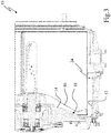
- FIG 3 shows a partial sectional side view of the washing tub 10 for the washer-dryer according to the preferred embodiment of the present invention.
- the laundry drum 24 is arranged inside the washing tub 10.
- a heater, not illustrated, is placed in the sump 16, so as to be able to heat the washing water collected therein.
- the duct 18 and faces the rear wall 50 of the laundry drum 24.
- the condenser 30 and the rear wall 14 of the washing tub 10 form a single body or a single-piece part.
- the condenser 30 may be also formed as a separate part and connected to the washing tub 10 by its inlet 20 and its outlet 40.
- the duct 18 facing the rear wall 50 of the laundry drum 24 allows that the hot and moisture-laden air stream exiting the drum 24 is directed from the laundry drum 24 towards the inlet 20 of the condenser 30.
- This duct ensures that substantially the whole air stream exiting the drum is admitted into the inlet 20 of the condenser. This improves the overall performances of the washer-dryer during the drying phase.
- the duct has the effect of improving the air circulation in the washer-dryer. Further, the duct reduces the turbulence of the air stream. The reduced turbulence of the air stream decrease the noise and also the time required for drying the laundry.
- the sensor 22 is placed inside the duct and in proximity of the inlet 20 of the condenser 30.
- the sensor 22 is a temperature sensor.
- the temperature sensor 22 in this position has the effect that the temperature of the air stream is detected at a meaningful position of the air stream cycle, where the hot and moisture-laden air stream exits the laundry drum 24, since substantially the whole or entire air stream passes in the duct. Thus, substantially the total air stream contacts the sensor 22.
- the temperature sensor 22 operates together with a further temperature sensor arranged in proximity of or in correspondence of the heater, not illustrated, placed in the sump 16.
- the drying cycle is controlled by activating or deactivating an air heater. Further, the drying cycle may be controlled by stopping the drying cycle.
- the control of the drying cycle depends on the temperatures detected by the temperature sensors. Preferably, the control of the drying cycle depends on the difference of the detected temperatures.
- a partition wall, septum and/or bulkhead 28 may be provided in the duct.
- the partition wall, septum and/or bulkhead is made in a single piece construction with the rear wall 14 of the tub 10.
- the partition wall, septum and/or bulkhead 28 have the effect of protecting the temperature sensor 22 placed in the duct from drops of water present in the bottom of the washing tub. For example, condensed water comes out from the condenser 30 or water remained in the bottom of the washing tub, e.g. from a previous washing cycle. These drops of water could compromise the temperature detection of the sensor.
- the partition wall is obtained along the whole length of the duct (i.e. from the sump 16 to the inlet 20 of the condenser 30).
- the partition wall, septum and/or bulkhead 28 subdivides the duct in a lower region 18a and in an upper region 18b, containing the sensor 22.
Landscapes
- Engineering & Computer Science (AREA)
- Textile Engineering (AREA)
- Detail Structures Of Washing Machines And Dryers (AREA)
- Main Body Construction Of Washing Machines And Laundry Dryers (AREA)
- Control Of Washing Machine And Dryer (AREA)
- Accessory Of Washing/Drying Machine, Commercial Washing/Drying Machine, Other Washing/Drying Machine (AREA)
- Processing Of Solid Wastes (AREA)
- Drying Of Solid Materials (AREA)
Abstract
Description
- The present invention relates to a washer-dryer with at least one condenser for condensing the moisture-laden air exiting the laundry during the drying cycle, according to the preamble of claim 1. Advantageously, the condenser and the rear wall of the washer-dryer are formed as a single-piece part.
- A typical washer-dryer includes an automatic control system, wherein the humidity of the laundry has to be determined. One or more sensors are arranged for detecting at least one specific parameter of the air stream flowing through the drying cycle. However, if the sensor is not able to detect variations of said parameter, then the performance of the automatic control system and of the washer-dryer is reduced.
-
WO 2007/138019 A1 discloses a washer-dryer comprising a temperature detection unit placed inside the washing tub. -
JP 7-47195 A -
GB 2 236 334 A -
EP 1 526 210 B1 discloses a washing machine control method using two temperature sensors. One temperature sensor is placed in the washing tub. The other temperature sensor is arranged in the air conduit for controlling the drying cycle. -
EP 1 500 739 A1 discloses a drying apparatus including a condensing duct and a blower duct respectively mounted on a rear surface and an upper surface of a water tub. The condensing duct has an ultrasonic atomizing unit, a condensing unit and a water adsorption unit therein, while the blower duct has a blower fan and a heater therein. An inner space of the condensing duct is partitioned into a first condensing path, a second condensing path and a third condensing path by a first air guide and a second air guide. -
US 2006/156766 A1 discloses a washing machine with a drying function including a water tub, a rotating tub mounted in the water tub so as to be rotatable, a driver rotating the rotating tub, a circulation passage defined so as to communicate with the water tub, a warm-air supply unit circularly supplying warm air through the circulation passage into the water tub and the rotating tub, a water-supply unit supplying water into the water tub, a control unit controlling the driver, the warm-air supply unit and the water-supply unit thereby to be capable of controlling wash, rinse, dehydration and drying steps, and a preheating unit executing a preheating operation in which warm air is supplied into the water tub and the rotating tub during rotation of the rotating tub before the wash step is executed. -
JP 2001-269495 A -
JP 2001-218994 A -
KR 10-2007-0015280 A - It is an object of the present invention to provide an improved washer-dryer with at least one condenser, wherein said washer-dryer allows a reliable detection of parameters in order to determine the humidity of the laundry.
- The object of the present invention is achieved by the washer-dryer according to claim 1.
- According to the present invention the rear wall of the washing tub comprises a duct which is fluidly connected to the inlet of the condenser, so that the air stream from the laundry drum to the inlet of the condenser passes the duct, and at least one sensor is arranged inside the duct.
- Advantageously the duct may be formed by an embossed area, or by a hollow or sunken area.
- The main idea of the present invention is the duct in the rear wall of the washing tub, advantageously facing the laundry drum, on the one hand, and the sensor inside said duct on the other hand. The almost total air stream from the laundry drum to the inlet of the condenser passes the duct and the sensor. This improves the performance of the washer-dryer during the drying cycle. Moreover this particular positioning of the sensor ensures that most of the air exiting the drum comes in contact with the sensor before entering the condenser, with the effect of ensuring that the sensor effectively detects the temperature of the air stream.
- For example, at least one temperature sensor is arranged inside the duct. Advantageously, at least one temperature sensor is arranged in proximity of the inlet of the condenser.
- Additionally, at least one further temperature sensor is arranged in proximity of a heater. The combination of both sensors allows an improved determination of the humidity of the laundry.
- Further, a partition wall, a septum and/or a bulkhead is provided in the duct in order to protect the sensor from water drops. Preferably, the partition wall, the septum and/or the bulkhead extends along the whole length of the duct.
- Advantageously the partition wall, septum and/or bulkhead is made in a single piece construction with the rear wall of the tub.
- Opportunely, the partition wall, septum and/or bulkhead subdivides the duct in a lower region and in an upper region containing the sensor.
- Advantageously, the washing tub comprises a sump in its lowermost position. In this case, the duct extends from the sump to the inlet of the condenser. Advantageously, a cylindrical curved wall of the laundry drum is perforated, so that the air stream from the laundry drum passes the sump of the washing tub.
- Preferably, the condenser and the rear wall of the washing tub are formed as a single body. In this case, the condenser and the rear wall of the washing tub may be formed as a single-piece part.
- The novel and inventive features believed to be the characteristic of the present invention are set forth in the appended claims.
- The invention will be described in further detail with reference to the drawings, in which
- FIG 1
- shows a schematic perspective view of a washing tub for a washer-dryer according to a preferred embodiment of the present invention,
- FIG 2
- shows a schematic front view of the washing tub for the washer-dryer according to the preferred embodiment of the present invention, and
- FIG 3
- shows a partial sectional side view of the washing tub for the washer-dryer according to the preferred embodiment of the present invention.
-
FIG 1 illustrates a schematic perspective view of awashing tub 10 for a washer-dryer according to a preferred embodiment of the present invention. Thewashing tub 10 is provided for receiving alaundry drum 24, which is not shown inFIG 1 . Saidlaundry drum 24 is rotatable inside thewashing tub 10. - The
washing tub 10 includes a cylindricallateral wall 12 and a preferably substantially plane or hemisphericalrear wall 14. The cylindricallateral wall 12 comprises asump 16 in its lowermost position. Therear wall 14 comprises a duct 18in its lower portion. - Advantageously, as illustrated in enclosed figures,
duct 18 may be formed by a hollow or sunken area (in enclosed figures coinciding with the duct 18), obtained in therear wall 14; in the embodiment illustrated in enclosed figures, this hollow orsunken area 18 extends between thesump 16 and aninlet 20 of acondenser 30 and therefore is fluidly connected to theinlet 20 of the condenser. - In a further embodiment,
duct 18 may be formed by an embossed area extending between thesump 16 and aninlet 20 of acondenser 30 and therefore fluidly connected to theinlet 20 of the condenser. - Advantageously, as for example illustrated in
Figure 3 , theduct 18 faces arear wall 50 of thelaundry drum 24. The duct is provided for an air stream from thelaundry drum 24 via thesump 16 to theinlet 20 of thecondenser 30. For example, the cylindrical curved wall of thelaundry drum 24 is perforated, so that the air stream can leave saidlaundry drum 24 above thesump 16 of thewashing tub 10. - As for example illustrated in
Figures 1 and2 , at least onesensor 22 is arranged inside the duct. Thesensor 22 is provided for detecting the humidity and/or the temperature of the air stream from thelaundry drum 24 to theinlet 20 of the condenser. In this example, the sensor is atemperature sensor 22. -
FIG 2 shows a schematic front view of thewashing tub 10 for the washer-dryer according to the preferred embodiment of the present invention. - The
washing tub 10 includes the cylindricallateral wall 12 and therear wall 14. Therear wall 14 is preferably substantially formed as a circular disk. Thesump 16 is in the lowermost position of the cylindricallateral wall 12. Theduct 18 preferably extends between thesump 16 and theinlet 20 of the condenser. The duct faces therear wall 50 of thelaundry drum 24. Thetemperature sensor 22 is arranged inside the duct. -
FIG 3 shows a partial sectional side view of thewashing tub 10 for the washer-dryer according to the preferred embodiment of the present invention. Thelaundry drum 24 is arranged inside thewashing tub 10. A heater, not illustrated, is placed in thesump 16, so as to be able to heat the washing water collected therein. Theduct 18 and faces therear wall 50 of thelaundry drum 24. - Preferably, the
condenser 30 and therear wall 14 of thewashing tub 10 form a single body or a single-piece part. However, thecondenser 30 may be also formed as a separate part and connected to thewashing tub 10 by itsinlet 20 and itsoutlet 40. - The
duct 18 facing therear wall 50 of thelaundry drum 24 allows that the hot and moisture-laden air stream exiting thedrum 24 is directed from thelaundry drum 24 towards theinlet 20 of thecondenser 30. This duct ensures that substantially the whole air stream exiting the drum is admitted into theinlet 20 of the condenser. This improves the overall performances of the washer-dryer during the drying phase. - Moreover, the duct has the effect of improving the air circulation in the washer-dryer. Further, the duct reduces the turbulence of the air stream. The reduced turbulence of the air stream decrease the noise and also the time required for drying the laundry.
- The
sensor 22 is placed inside the duct and in proximity of theinlet 20 of thecondenser 30. For example, thesensor 22 is a temperature sensor. Thetemperature sensor 22 in this position has the effect that the temperature of the air stream is detected at a meaningful position of the air stream cycle, where the hot and moisture-laden air stream exits thelaundry drum 24, since substantially the whole or entire air stream passes in the duct. Thus, substantially the total air stream contacts thesensor 22. - Preferably, the
temperature sensor 22 operates together with a further temperature sensor arranged in proximity of or in correspondence of the heater, not illustrated, placed in thesump 16. For example, the drying cycle is controlled by activating or deactivating an air heater. Further, the drying cycle may be controlled by stopping the drying cycle. The control of the drying cycle depends on the temperatures detected by the temperature sensors. Preferably, the control of the drying cycle depends on the difference of the detected temperatures. - A partition wall, septum and/or
bulkhead 28 may be provided in the duct. Preferably the partition wall, septum and/or bulkhead is made in a single piece construction with therear wall 14 of thetub 10. The partition wall, septum and/orbulkhead 28 have the effect of protecting thetemperature sensor 22 placed in the duct from drops of water present in the bottom of the washing tub. For example, condensed water comes out from thecondenser 30 or water remained in the bottom of the washing tub, e.g. from a previous washing cycle. These drops of water could compromise the temperature detection of the sensor. Preferably the partition wall is obtained along the whole length of the duct (i.e. from thesump 16 to theinlet 20 of the condenser 30). - Advantageously the partition wall, septum and/or
bulkhead 28 subdivides the duct in alower region 18a and in anupper region 18b, containing thesensor 22. - Although an illustrative embodiment of the present invention has been described herein with reference to the accompanying drawings, it is to be understood that the present invention is not limited to this precise embodiment, and that various other changes and modifications may be affected therein by one skilled in the art without departing from the scope or spirit of the invention. All such changes and modifications are intended to be included within the scope of the invention as defined by the appended claims.
-
- 10
- washing tub
- 12
- lateral wall
- 14
- rear wall
- 16
- sump
- 18
- duct
- 18a
- lower region
- 18b
- upper region
- 20
- inlet of the condenser
- 22
- sensor, temperature sensor
- 24
- laundry drum
- 28
- partition wall, septum and/or bulkhead
- 30
- condenser
- 40
- outlet of the condenser
- 50
- rear wall of the drum
Claims (13)
- A washer-dryer comprising:- a washing tub (10) comprising a cylindrical lateral wall (12) and a rear wall (14),- a rotatable laundry drum (24) arranged or arrangeable inside the washing tub (10),- a condenser (30) for condensing moisture-laden air exiting the laundry during a drying cycle;wherein:- an inlet (20) of the condenser (30) is arranged at or connected to the rear wall (14) of the washing tub (10),- an outlet (40) of the condenser is connected to the washing tub (10),characterized by
a duct in the rear wall (14) of the washing tub (10) formed by an embossed area or by a hollow or sunken area, the duct (18) fluidly connected to the inlet (20) of said condenser (30), so that the air stream from the laundry drum (24) to the inlet (20) of the condenser passes said duct (18), wherein at least one temperature sensor (22) detecting the temperature of said air stream is arranged inside the duct (18). - The washer-dryer according to claim 1,
characterized in that
said duct (18) faces a rear wall (50) of said drum (24). - The washer-dryer according to claim 1 or 2,
characterized in that
at least one temperature sensor (22) is arranged in proximity of the inlet (20) of the condenser (30). - The washer-dryer according to any one of the preceding claims,
characterized in that
at least one further temperature sensor is arranged in proximity of a heater. - The washer-dryer according to any one of the preceding claims,
characterized in that
a partition wall, a septum and/or a bulkhead (28) is provided in the duct (18) in order to protect the sensor (22) from water drops. - The washer-dryer according to claim 5,
characterized in that
the partition wall, the septum and/or the bulkhead (28) extends along the whole length of the duct (18). - The washer-dryer according to claim 5 or 6,
characterized in that
said partition wall, septum and/or bulkhead (28) is made in a single piece construction with the rear wall (14) of the tub (10). - The washer-dryer according to claim 5 or 6 or 7,
characterized in that
said partition wall, septum and/or bulkhead (28) subdivides said duct (18) in a lower region (18a) and in an upper region (18b) containing said sensor (22). - The washer-dryer according to any one of the preceding claims,
characterized in that
the washing tub (10) comprises a sump (16) in its lowermost position, where at least one further temperature sensor is arranged. - The washer-dryer according to claim 9,
characterized in that
said duct (18) extends from the sump (16) to the inlet (20) of the condenser (30). - The washer-dryer according to claim 9 and 10,
characterized in that
a cylindrical curved wall of the laundry drum (24) is perforated, so that the air stream from the laundry drum (24) passes to the sump (16) of the washing tub (10). - The washer-dryer according to any one of the preceding claims,
characterized in that
the condenser (30) and the rear wall (14) of the washing tub (10) are formed as a single body. - The washer-dryer according to claim 12,
characterized in, that
the condenser (30) and the rear wall (14) of the washing tub (10) are formed as a single-piece part.
Priority Applications (1)
| Application Number | Priority Date | Filing Date | Title |
|---|---|---|---|
| EP20169978.2A EP3719194A1 (en) | 2011-09-19 | 2012-09-18 | A washer-dryer with at least one condenser |
Applications Claiming Priority (3)
| Application Number | Priority Date | Filing Date | Title |
|---|---|---|---|
| EP11181824A EP2570548A1 (en) | 2011-09-19 | 2011-09-19 | A washer-dryer with at least one condenser |
| PCT/EP2012/068318 WO2013041513A1 (en) | 2011-09-19 | 2012-09-18 | A washer-dryer with at least one condenser |
| EP12759465.3A EP2758583B2 (en) | 2011-09-19 | 2012-09-18 | A washer-dryer with at least one condenser |
Related Parent Applications (2)
| Application Number | Title | Priority Date | Filing Date |
|---|---|---|---|
| EP12759465.3A Division EP2758583B2 (en) | 2011-09-19 | 2012-09-18 | A washer-dryer with at least one condenser |
| EP12759465.3A Division-Into EP2758583B2 (en) | 2011-09-19 | 2012-09-18 | A washer-dryer with at least one condenser |
Related Child Applications (2)
| Application Number | Title | Priority Date | Filing Date |
|---|---|---|---|
| EP20169978.2A Division EP3719194A1 (en) | 2011-09-19 | 2012-09-18 | A washer-dryer with at least one condenser |
| EP20169978.2A Division-Into EP3719194A1 (en) | 2011-09-19 | 2012-09-18 | A washer-dryer with at least one condenser |
Publications (2)
| Publication Number | Publication Date |
|---|---|
| EP3492645A1 true EP3492645A1 (en) | 2019-06-05 |
| EP3492645B1 EP3492645B1 (en) | 2020-09-16 |
Family
ID=45531623
Family Applications (4)
| Application Number | Title | Priority Date | Filing Date |
|---|---|---|---|
| EP11181824A Withdrawn EP2570548A1 (en) | 2011-09-19 | 2011-09-19 | A washer-dryer with at least one condenser |
| EP20169978.2A Withdrawn EP3719194A1 (en) | 2011-09-19 | 2012-09-18 | A washer-dryer with at least one condenser |
| EP12759465.3A Active EP2758583B2 (en) | 2011-09-19 | 2012-09-18 | A washer-dryer with at least one condenser |
| EP18215263.7A Active EP3492645B1 (en) | 2011-09-19 | 2012-09-18 | A washer-dryer with at least one condenser |
Family Applications Before (3)
| Application Number | Title | Priority Date | Filing Date |
|---|---|---|---|
| EP11181824A Withdrawn EP2570548A1 (en) | 2011-09-19 | 2011-09-19 | A washer-dryer with at least one condenser |
| EP20169978.2A Withdrawn EP3719194A1 (en) | 2011-09-19 | 2012-09-18 | A washer-dryer with at least one condenser |
| EP12759465.3A Active EP2758583B2 (en) | 2011-09-19 | 2012-09-18 | A washer-dryer with at least one condenser |
Country Status (11)
| Country | Link |
|---|---|
| US (1) | US10407818B2 (en) |
| EP (4) | EP2570548A1 (en) |
| CN (2) | CN107523976B (en) |
| AU (1) | AU2012311672B2 (en) |
| BR (1) | BR112014006426A2 (en) |
| ES (2) | ES2837418T3 (en) |
| PL (1) | PL2758583T5 (en) |
| PT (1) | PT2758583T (en) |
| RU (1) | RU2014115767A (en) |
| TR (1) | TR201909263T4 (en) |
| WO (1) | WO2013041513A1 (en) |
Cited By (1)
| Publication number | Priority date | Publication date | Assignee | Title |
|---|---|---|---|---|
| WO2021023286A1 (en) * | 2019-08-08 | 2021-02-11 | 青岛海尔洗衣机有限公司 | Drying air passage device, laundry treatment apparatus and control method |
Families Citing this family (4)
| Publication number | Priority date | Publication date | Assignee | Title |
|---|---|---|---|---|
| EP2570548A1 (en) | 2011-09-19 | 2013-03-20 | Electrolux Home Products Corporation N.V. | A washer-dryer with at least one condenser |
| EP3330428B1 (en) * | 2016-11-30 | 2020-11-18 | BSH Hausgeräte GmbH | Tub of a clothes drying appliance |
| CN113265861B (en) * | 2021-05-17 | 2026-02-10 | 青岛海尔洗衣机有限公司 | A garment processing device and its control method |
| CN118147889B (en) * | 2024-05-09 | 2024-07-09 | 珠海格力电器股份有限公司 | Outer cylinder assembly and wall-mounted clothes treatment equipment |
Citations (9)
| Publication number | Priority date | Publication date | Assignee | Title |
|---|---|---|---|---|
| JPH0698991A (en) * | 1992-08-05 | 1994-04-12 | Sanyo Electric Co Ltd | Dryer |
| JP2001269495A (en) * | 2000-03-24 | 2001-10-02 | Sharp Corp | Drum type washing machine |
| KR20040046209A (en) * | 2002-11-26 | 2004-06-05 | 엘지전자 주식회사 | method for cycle of washing machine with dryer |
| EP1500739A1 (en) * | 2003-07-24 | 2005-01-26 | Samsung Electronics Co., Ltd. | Drying apparatus and washing machine having the same |
| CN1611659A (en) * | 2003-10-30 | 2005-05-04 | 乐金电子(天津)电器有限公司 | Drying devcie for drum washing machine and its control method |
| EP1666655A2 (en) * | 2004-12-02 | 2006-06-07 | Samsung Electronics Co., Ltd. | Eliminating wrinkles in laundry |
| WO2007138019A1 (en) * | 2006-05-31 | 2007-12-06 | BSH Bosch und Siemens Hausgeräte GmbH | A drum washing machine and a control method for the same |
| EP2019163A1 (en) * | 2007-07-26 | 2009-01-28 | CANDY S.p.A. | Washer dryer machine |
| WO2010060781A1 (en) * | 2008-11-25 | 2010-06-03 | BSH Bosch und Siemens Hausgeräte GmbH | Laundry drying appliance comprising a process air circuit and a sensor placed therein |
Family Cites Families (35)
| Publication number | Priority date | Publication date | Assignee | Title |
|---|---|---|---|---|
| US2607209A (en) * | 1948-06-09 | 1952-08-19 | Bendix Home Appliances Inc | Combination washer and drier |
| JPS6098991A (en) | 1983-11-04 | 1985-06-01 | Ajinomoto Co Inc | Production of l-phenylalanine by fermentation |
| SE464710B (en) * | 1989-09-22 | 1991-06-03 | Asko Cylinda Ab | DRYER |
| IT1234703B (en) | 1989-09-29 | 1992-05-26 | Zanussi A Spa Industrie | TEMPERATURE CONTROL DEVICE FOR COMBINED MACHINE FOR LAUNDRY WASHING AND DRYING |
| JPH0775640B2 (en) * | 1992-08-24 | 1995-08-16 | 三洋電機株式会社 | Dryer |
| JPH0747195A (en) | 1993-08-05 | 1995-02-21 | Matsushita Electric Ind Co Ltd | Drum washer dryer |
| JP3346993B2 (en) | 1996-09-13 | 2002-11-18 | 株式会社東芝 | Washing and drying machine |
| US7534304B2 (en) * | 1997-04-29 | 2009-05-19 | Whirlpool Corporation | Non-aqueous washing machine and methods |
| JPH117195A (en) | 1997-06-17 | 1999-01-12 | Minolta Co Ltd | Developing device |
| JP3517618B2 (en) † | 1999-10-21 | 2004-04-12 | 株式会社東芝 | Drum type washer / dryer |
| JP2001218994A (en) * | 2000-02-08 | 2001-08-14 | Toshiba Corp | Drum type washer / dryer |
| JP4377576B2 (en) * | 2002-11-11 | 2009-12-02 | 株式会社東芝 | Washing and drying machine |
| KR100480929B1 (en) * | 2003-08-12 | 2005-04-07 | 엘지전자 주식회사 | Method for controlling drying of tumble drier |
| EP1524361B1 (en) * | 2003-10-18 | 2006-10-04 | Lg Electronics Inc. | Condensing apparatus for washing and drying machine |
| AU2004210559B2 (en) | 2003-10-21 | 2010-07-22 | Lg Electronics Inc. | Washing machine and control method thereof |
| JP2006198149A (en) * | 2005-01-20 | 2006-08-03 | Toshiba Corp | Washing machine with drying function |
| KR20060097210A (en) * | 2005-03-04 | 2006-09-14 | 삼성전자주식회사 | Washing machine and its foaming method |
| KR101155486B1 (en) | 2005-07-30 | 2012-06-15 | 엘지전자 주식회사 | Drying method of combined washing machine |
| KR100631574B1 (en) * | 2005-08-13 | 2006-10-09 | 엘지전자 주식회사 | Condensation Laundry Dryer |
| PL1917392T3 (en) * | 2005-08-25 | 2017-10-31 | Lg Electronics Inc | Operating method for laundry machine |
| KR101215449B1 (en) * | 2007-05-16 | 2012-12-26 | 삼성전자주식회사 | Washing machine |
| EP2019160B1 (en) † | 2007-07-26 | 2010-09-22 | Candy S.p.A. | Washer-drier machine |
| US7966683B2 (en) * | 2007-08-31 | 2011-06-28 | Whirlpool Corporation | Method for operating a steam generator in a fabric treatment appliance |
| KR100898930B1 (en) * | 2007-09-04 | 2009-05-26 | 엘지전자 주식회사 | Drying temperature and humidity control device |
| ES2359025T3 (en) * | 2007-10-18 | 2011-05-17 | Electrolux Home Products Corporation N.V. | DRYER WASHER THAT USES A WASHING FLUID AND THAT IS EQUIPPED WITH A COMBINED FILTER ASSEMBLY. |
| ATE475740T1 (en) * | 2008-04-10 | 2010-08-15 | Bonferraro Spa | WASHING/DRYING DEVICE AND APPROPRIATE OPERATING CYCLE |
| JP5048576B2 (en) † | 2008-04-17 | 2012-10-17 | シャープ株式会社 | Dryer and washing dryer |
| DE102008020556A1 (en) * | 2008-04-24 | 2009-10-29 | BSH Bosch und Siemens Hausgeräte GmbH | Exhaust air dryer with reduced condensate formation and method for its operation |
| JP2009297282A (en) | 2008-06-13 | 2009-12-24 | Mitsubishi Electric Corp | Clothes dryer or washing and drying machine |
| CN101684610B (en) * | 2008-09-26 | 2011-11-09 | 博西华电器(江苏)有限公司 | Clothes drying device |
| US20100100111A1 (en) * | 2008-10-21 | 2010-04-22 | Rogerson John S | Apparatus and method for surgery |
| CN201386218Y (en) * | 2009-03-02 | 2010-01-20 | 博西华电器(江苏)有限公司 | Household clothing drying equipment |
| EP2570548A1 (en) | 2011-09-19 | 2013-03-20 | Electrolux Home Products Corporation N.V. | A washer-dryer with at least one condenser |
| EP2634302B1 (en) † | 2012-02-29 | 2016-10-19 | Electrolux Home Products Corporation N.V. | Laundry machine with sensor unit |
| JP6098991B2 (en) | 2012-12-14 | 2017-03-22 | ブラザー工業株式会社 | Sheet transport device |
-
2011
- 2011-09-19 EP EP11181824A patent/EP2570548A1/en not_active Withdrawn
-
2012
- 2012-09-18 RU RU2014115767/12A patent/RU2014115767A/en not_active Application Discontinuation
- 2012-09-18 US US14/345,536 patent/US10407818B2/en active Active
- 2012-09-18 ES ES18215263T patent/ES2837418T3/en active Active
- 2012-09-18 ES ES12759465T patent/ES2732701T5/en active Active
- 2012-09-18 BR BR112014006426A patent/BR112014006426A2/en not_active Application Discontinuation
- 2012-09-18 AU AU2012311672A patent/AU2012311672B2/en active Active
- 2012-09-18 PT PT12759465T patent/PT2758583T/en unknown
- 2012-09-18 PL PL12759465.3T patent/PL2758583T5/en unknown
- 2012-09-18 EP EP20169978.2A patent/EP3719194A1/en not_active Withdrawn
- 2012-09-18 CN CN201710618829.1A patent/CN107523976B/en active Active
- 2012-09-18 EP EP12759465.3A patent/EP2758583B2/en active Active
- 2012-09-18 EP EP18215263.7A patent/EP3492645B1/en active Active
- 2012-09-18 WO PCT/EP2012/068318 patent/WO2013041513A1/en not_active Ceased
- 2012-09-18 TR TR2019/09263T patent/TR201909263T4/en unknown
- 2012-09-18 CN CN201280053405.0A patent/CN103946442B/en active Active
Patent Citations (9)
| Publication number | Priority date | Publication date | Assignee | Title |
|---|---|---|---|---|
| JPH0698991A (en) * | 1992-08-05 | 1994-04-12 | Sanyo Electric Co Ltd | Dryer |
| JP2001269495A (en) * | 2000-03-24 | 2001-10-02 | Sharp Corp | Drum type washing machine |
| KR20040046209A (en) * | 2002-11-26 | 2004-06-05 | 엘지전자 주식회사 | method for cycle of washing machine with dryer |
| EP1500739A1 (en) * | 2003-07-24 | 2005-01-26 | Samsung Electronics Co., Ltd. | Drying apparatus and washing machine having the same |
| CN1611659A (en) * | 2003-10-30 | 2005-05-04 | 乐金电子(天津)电器有限公司 | Drying devcie for drum washing machine and its control method |
| EP1666655A2 (en) * | 2004-12-02 | 2006-06-07 | Samsung Electronics Co., Ltd. | Eliminating wrinkles in laundry |
| WO2007138019A1 (en) * | 2006-05-31 | 2007-12-06 | BSH Bosch und Siemens Hausgeräte GmbH | A drum washing machine and a control method for the same |
| EP2019163A1 (en) * | 2007-07-26 | 2009-01-28 | CANDY S.p.A. | Washer dryer machine |
| WO2010060781A1 (en) * | 2008-11-25 | 2010-06-03 | BSH Bosch und Siemens Hausgeräte GmbH | Laundry drying appliance comprising a process air circuit and a sensor placed therein |
Cited By (1)
| Publication number | Priority date | Publication date | Assignee | Title |
|---|---|---|---|---|
| WO2021023286A1 (en) * | 2019-08-08 | 2021-02-11 | 青岛海尔洗衣机有限公司 | Drying air passage device, laundry treatment apparatus and control method |
Also Published As
| Publication number | Publication date |
|---|---|
| EP3719194A1 (en) | 2020-10-07 |
| EP3492645B1 (en) | 2020-09-16 |
| EP2758583A1 (en) | 2014-07-30 |
| CN107523976B (en) | 2020-12-25 |
| ES2732701T3 (en) | 2019-11-25 |
| US10407818B2 (en) | 2019-09-10 |
| RU2014115767A (en) | 2015-10-27 |
| US20140338404A1 (en) | 2014-11-20 |
| CN103946442B (en) | 2017-09-12 |
| ES2837418T3 (en) | 2021-06-30 |
| EP2570548A1 (en) | 2013-03-20 |
| PT2758583T (en) | 2019-07-05 |
| CN107523976A (en) | 2017-12-29 |
| WO2013041513A1 (en) | 2013-03-28 |
| EP2758583B1 (en) | 2019-04-03 |
| CN103946442A (en) | 2014-07-23 |
| BR112014006426A2 (en) | 2017-04-11 |
| AU2012311672B2 (en) | 2017-05-04 |
| PL2758583T5 (en) | 2023-01-09 |
| AU2012311672A1 (en) | 2014-03-27 |
| TR201909263T4 (en) | 2019-07-22 |
| EP2758583B2 (en) | 2022-08-24 |
| ES2732701T5 (en) | 2022-11-02 |
| PL2758583T3 (en) | 2019-10-31 |
Similar Documents
| Publication | Publication Date | Title |
|---|---|---|
| EP2489777B1 (en) | Clothing dryer and washer dryer | |
| US7866059B2 (en) | Method of controlling a dryer | |
| EP3492645B1 (en) | A washer-dryer with at least one condenser | |
| CN103046298A (en) | Laundry machine and controlling method thereof | |
| US20150059200A1 (en) | Dryer appliance and a method for operating the same | |
| CN107489008B (en) | Method for operating a condensation dryer and condensation dryer | |
| KR20090114785A (en) | Heater unit and clothes treating apparatus having same | |
| WO2013088362A1 (en) | Washer dryer with a temperature sensor and process for its operation | |
| CN205420864U (en) | Dryer containing water -cooled condensing equipment | |
| WO2006041266A1 (en) | Condensing type dryer and controlling method of the same | |
| US20130145644A1 (en) | Process for operating a washer dryer with a sensor placed between a tub and a heat exchanger, and related washer dryer | |
| EP2392717B1 (en) | Washing apparatus and control method thereof | |
| JP2011067233A (en) | Drum washing and drying machine | |
| JP2005137503A (en) | Clothes dryer | |
| KR20130074790A (en) | Cloth treating apparatus | |
| KR101861668B1 (en) | Cloth treating apparatus | |
| JP5597373B2 (en) | Clothes dryer | |
| JP3806655B2 (en) | Drum type washer / dryer | |
| JP2006122697A (en) | Drum type washing and drying machine | |
| JP2005124761A (en) | Drum type washer / dryer | |
| KR20120135693A (en) | Method of drying ending time controlling drying machine of use heat pump | |
| JP5517874B2 (en) | Drum type washer / dryer | |
| JPH0739694A (en) | Drum washer dryer | |
| JP6564270B2 (en) | Washing machine | |
| JP2005137507A (en) | Drum type washer / dryer |
Legal Events
| Date | Code | Title | Description |
|---|---|---|---|
| PUAI | Public reference made under article 153(3) epc to a published international application that has entered the european phase |
Free format text: ORIGINAL CODE: 0009012 |
|
| STAA | Information on the status of an ep patent application or granted ep patent |
Free format text: STATUS: THE APPLICATION HAS BEEN PUBLISHED |
|
| AC | Divisional application: reference to earlier application |
Ref document number: 2758583 Country of ref document: EP Kind code of ref document: P |
|
| AK | Designated contracting states |
Kind code of ref document: A1 Designated state(s): AL AT BE BG CH CY CZ DE DK EE ES FI FR GB GR HR HU IE IS IT LI LT LU LV MC MK MT NL NO PL PT RO RS SE SI SK SM TR |
|
| STAA | Information on the status of an ep patent application or granted ep patent |
Free format text: STATUS: REQUEST FOR EXAMINATION WAS MADE |
|
| 17P | Request for examination filed |
Effective date: 20191205 |
|
| RBV | Designated contracting states (corrected) |
Designated state(s): AL AT BE BG CH CY CZ DE DK EE ES FI FR GB GR HR HU IE IS IT LI LT LU LV MC MK MT NL NO PL PT RO RS SE SI SK SM TR |
|
| REG | Reference to a national code |
Ref country code: DE Ref legal event code: R079 Ref document number: 602012072405 Country of ref document: DE Free format text: PREVIOUS MAIN CLASS: D06F0025000000 Ipc: D06F0058300000 |
|
| GRAP | Despatch of communication of intention to grant a patent |
Free format text: ORIGINAL CODE: EPIDOSNIGR1 |
|
| STAA | Information on the status of an ep patent application or granted ep patent |
Free format text: STATUS: GRANT OF PATENT IS INTENDED |
|
| RIC1 | Information provided on ipc code assigned before grant |
Ipc: D06F 58/30 20200101AFI20200212BHEP Ipc: D06F 58/24 20060101ALI20200212BHEP Ipc: D06F 25/00 20060101ALI20200212BHEP Ipc: D06F 58/20 20060101ALI20200212BHEP Ipc: D06F 58/38 20200101ALI20200212BHEP Ipc: D06F 58/52 20200101ALI20200212BHEP |
|
| INTG | Intention to grant announced |
Effective date: 20200227 |
|
| GRAS | Grant fee paid |
Free format text: ORIGINAL CODE: EPIDOSNIGR3 |
|
| GRAA | (expected) grant |
Free format text: ORIGINAL CODE: 0009210 |
|
| STAA | Information on the status of an ep patent application or granted ep patent |
Free format text: STATUS: THE PATENT HAS BEEN GRANTED |
|
| AC | Divisional application: reference to earlier application |
Ref document number: 2758583 Country of ref document: EP Kind code of ref document: P |
|
| AK | Designated contracting states |
Kind code of ref document: B1 Designated state(s): AL AT BE BG CH CY CZ DE DK EE ES FI FR GB GR HR HU IE IS IT LI LT LU LV MC MK MT NL NO PL PT RO RS SE SI SK SM TR |
|
| REG | Reference to a national code |
Ref country code: GB Ref legal event code: FG4D |
|
| REG | Reference to a national code |
Ref country code: CH Ref legal event code: EP |
|
| REG | Reference to a national code |
Ref country code: DE Ref legal event code: R096 Ref document number: 602012072405 Country of ref document: DE |
|
| REG | Reference to a national code |
Ref country code: IE Ref legal event code: FG4D |
|
| REG | Reference to a national code |
Ref country code: AT Ref legal event code: REF Ref document number: 1314267 Country of ref document: AT Kind code of ref document: T Effective date: 20201015 |
|
| REG | Reference to a national code |
Ref country code: NL Ref legal event code: FP |
|
| PG25 | Lapsed in a contracting state [announced via postgrant information from national office to epo] |
Ref country code: GR Free format text: LAPSE BECAUSE OF FAILURE TO SUBMIT A TRANSLATION OF THE DESCRIPTION OR TO PAY THE FEE WITHIN THE PRESCRIBED TIME-LIMIT Effective date: 20201217 Ref country code: NO Free format text: LAPSE BECAUSE OF FAILURE TO SUBMIT A TRANSLATION OF THE DESCRIPTION OR TO PAY THE FEE WITHIN THE PRESCRIBED TIME-LIMIT Effective date: 20201216 Ref country code: BG Free format text: LAPSE BECAUSE OF FAILURE TO SUBMIT A TRANSLATION OF THE DESCRIPTION OR TO PAY THE FEE WITHIN THE PRESCRIBED TIME-LIMIT Effective date: 20201216 Ref country code: FI Free format text: LAPSE BECAUSE OF FAILURE TO SUBMIT A TRANSLATION OF THE DESCRIPTION OR TO PAY THE FEE WITHIN THE PRESCRIBED TIME-LIMIT Effective date: 20200916 Ref country code: HR Free format text: LAPSE BECAUSE OF FAILURE TO SUBMIT A TRANSLATION OF THE DESCRIPTION OR TO PAY THE FEE WITHIN THE PRESCRIBED TIME-LIMIT Effective date: 20200916 Ref country code: SE Free format text: LAPSE BECAUSE OF FAILURE TO SUBMIT A TRANSLATION OF THE DESCRIPTION OR TO PAY THE FEE WITHIN THE PRESCRIBED TIME-LIMIT Effective date: 20200916 |
|
| REG | Reference to a national code |
Ref country code: AT Ref legal event code: MK05 Ref document number: 1314267 Country of ref document: AT Kind code of ref document: T Effective date: 20200916 |
|
| PG25 | Lapsed in a contracting state [announced via postgrant information from national office to epo] |
Ref country code: LV Free format text: LAPSE BECAUSE OF FAILURE TO SUBMIT A TRANSLATION OF THE DESCRIPTION OR TO PAY THE FEE WITHIN THE PRESCRIBED TIME-LIMIT Effective date: 20200916 Ref country code: RS Free format text: LAPSE BECAUSE OF FAILURE TO SUBMIT A TRANSLATION OF THE DESCRIPTION OR TO PAY THE FEE WITHIN THE PRESCRIBED TIME-LIMIT Effective date: 20200916 |
|
| REG | Reference to a national code |
Ref country code: LT Ref legal event code: MG4D |
|
| PG25 | Lapsed in a contracting state [announced via postgrant information from national office to epo] |
Ref country code: EE Free format text: LAPSE BECAUSE OF FAILURE TO SUBMIT A TRANSLATION OF THE DESCRIPTION OR TO PAY THE FEE WITHIN THE PRESCRIBED TIME-LIMIT Effective date: 20200916 Ref country code: CZ Free format text: LAPSE BECAUSE OF FAILURE TO SUBMIT A TRANSLATION OF THE DESCRIPTION OR TO PAY THE FEE WITHIN THE PRESCRIBED TIME-LIMIT Effective date: 20200916 Ref country code: PT Free format text: LAPSE BECAUSE OF FAILURE TO SUBMIT A TRANSLATION OF THE DESCRIPTION OR TO PAY THE FEE WITHIN THE PRESCRIBED TIME-LIMIT Effective date: 20210118 Ref country code: RO Free format text: LAPSE BECAUSE OF FAILURE TO SUBMIT A TRANSLATION OF THE DESCRIPTION OR TO PAY THE FEE WITHIN THE PRESCRIBED TIME-LIMIT Effective date: 20200916 Ref country code: SM Free format text: LAPSE BECAUSE OF FAILURE TO SUBMIT A TRANSLATION OF THE DESCRIPTION OR TO PAY THE FEE WITHIN THE PRESCRIBED TIME-LIMIT Effective date: 20200916 Ref country code: LT Free format text: LAPSE BECAUSE OF FAILURE TO SUBMIT A TRANSLATION OF THE DESCRIPTION OR TO PAY THE FEE WITHIN THE PRESCRIBED TIME-LIMIT Effective date: 20200916 |
|
| REG | Reference to a national code |
Ref country code: CH Ref legal event code: PL |
|
| PG25 | Lapsed in a contracting state [announced via postgrant information from national office to epo] |
Ref country code: AT Free format text: LAPSE BECAUSE OF FAILURE TO SUBMIT A TRANSLATION OF THE DESCRIPTION OR TO PAY THE FEE WITHIN THE PRESCRIBED TIME-LIMIT Effective date: 20200916 Ref country code: AL Free format text: LAPSE BECAUSE OF FAILURE TO SUBMIT A TRANSLATION OF THE DESCRIPTION OR TO PAY THE FEE WITHIN THE PRESCRIBED TIME-LIMIT Effective date: 20200916 Ref country code: IS Free format text: LAPSE BECAUSE OF FAILURE TO SUBMIT A TRANSLATION OF THE DESCRIPTION OR TO PAY THE FEE WITHIN THE PRESCRIBED TIME-LIMIT Effective date: 20210116 |
|
| REG | Reference to a national code |
Ref country code: DE Ref legal event code: R097 Ref document number: 602012072405 Country of ref document: DE |
|
| PG25 | Lapsed in a contracting state [announced via postgrant information from national office to epo] |
Ref country code: SK Free format text: LAPSE BECAUSE OF FAILURE TO SUBMIT A TRANSLATION OF THE DESCRIPTION OR TO PAY THE FEE WITHIN THE PRESCRIBED TIME-LIMIT Effective date: 20200916 Ref country code: LU Free format text: LAPSE BECAUSE OF NON-PAYMENT OF DUE FEES Effective date: 20200918 Ref country code: MC Free format text: LAPSE BECAUSE OF FAILURE TO SUBMIT A TRANSLATION OF THE DESCRIPTION OR TO PAY THE FEE WITHIN THE PRESCRIBED TIME-LIMIT Effective date: 20200916 |
|
| REG | Reference to a national code |
Ref country code: ES Ref legal event code: FG2A Ref document number: 2837418 Country of ref document: ES Kind code of ref document: T3 Effective date: 20210630 |
|
| PLBE | No opposition filed within time limit |
Free format text: ORIGINAL CODE: 0009261 |
|
| STAA | Information on the status of an ep patent application or granted ep patent |
Free format text: STATUS: NO OPPOSITION FILED WITHIN TIME LIMIT |
|
| 26N | No opposition filed |
Effective date: 20210617 |
|
| PG25 | Lapsed in a contracting state [announced via postgrant information from national office to epo] |
Ref country code: IE Free format text: LAPSE BECAUSE OF NON-PAYMENT OF DUE FEES Effective date: 20200918 Ref country code: DK Free format text: LAPSE BECAUSE OF FAILURE TO SUBMIT A TRANSLATION OF THE DESCRIPTION OR TO PAY THE FEE WITHIN THE PRESCRIBED TIME-LIMIT Effective date: 20200916 Ref country code: SI Free format text: LAPSE BECAUSE OF FAILURE TO SUBMIT A TRANSLATION OF THE DESCRIPTION OR TO PAY THE FEE WITHIN THE PRESCRIBED TIME-LIMIT Effective date: 20200916 Ref country code: CH Free format text: LAPSE BECAUSE OF NON-PAYMENT OF DUE FEES Effective date: 20200930 Ref country code: LI Free format text: LAPSE BECAUSE OF NON-PAYMENT OF DUE FEES Effective date: 20200930 |
|
| PG25 | Lapsed in a contracting state [announced via postgrant information from national office to epo] |
Ref country code: MT Free format text: LAPSE BECAUSE OF FAILURE TO SUBMIT A TRANSLATION OF THE DESCRIPTION OR TO PAY THE FEE WITHIN THE PRESCRIBED TIME-LIMIT Effective date: 20200916 Ref country code: CY Free format text: LAPSE BECAUSE OF FAILURE TO SUBMIT A TRANSLATION OF THE DESCRIPTION OR TO PAY THE FEE WITHIN THE PRESCRIBED TIME-LIMIT Effective date: 20200916 |
|
| PG25 | Lapsed in a contracting state [announced via postgrant information from national office to epo] |
Ref country code: MK Free format text: LAPSE BECAUSE OF FAILURE TO SUBMIT A TRANSLATION OF THE DESCRIPTION OR TO PAY THE FEE WITHIN THE PRESCRIBED TIME-LIMIT Effective date: 20200916 |
|
| PGFP | Annual fee paid to national office [announced via postgrant information from national office to epo] |
Ref country code: NL Payment date: 20220920 Year of fee payment: 11 |
|
| PGFP | Annual fee paid to national office [announced via postgrant information from national office to epo] |
Ref country code: FR Payment date: 20220921 Year of fee payment: 11 Ref country code: BE Payment date: 20220920 Year of fee payment: 11 |
|
| PGFP | Annual fee paid to national office [announced via postgrant information from national office to epo] |
Ref country code: ES Payment date: 20221122 Year of fee payment: 11 |
|
| P01 | Opt-out of the competence of the unified patent court (upc) registered |
Effective date: 20230625 |
|
| REG | Reference to a national code |
Ref country code: NL Ref legal event code: MM Effective date: 20231001 |
|
| REG | Reference to a national code |
Ref country code: BE Ref legal event code: MM Effective date: 20230930 |
|
| PG25 | Lapsed in a contracting state [announced via postgrant information from national office to epo] |
Ref country code: NL Free format text: LAPSE BECAUSE OF NON-PAYMENT OF DUE FEES Effective date: 20231001 |
|
| PG25 | Lapsed in a contracting state [announced via postgrant information from national office to epo] |
Ref country code: NL Free format text: LAPSE BECAUSE OF NON-PAYMENT OF DUE FEES Effective date: 20231001 |
|
| PG25 | Lapsed in a contracting state [announced via postgrant information from national office to epo] |
Ref country code: FR Free format text: LAPSE BECAUSE OF NON-PAYMENT OF DUE FEES Effective date: 20230930 |
|
| PG25 | Lapsed in a contracting state [announced via postgrant information from national office to epo] |
Ref country code: BE Free format text: LAPSE BECAUSE OF NON-PAYMENT OF DUE FEES Effective date: 20230930 |
|
| REG | Reference to a national code |
Ref country code: ES Ref legal event code: FD2A Effective date: 20241030 |
|
| PG25 | Lapsed in a contracting state [announced via postgrant information from national office to epo] |
Ref country code: ES Free format text: LAPSE BECAUSE OF NON-PAYMENT OF DUE FEES Effective date: 20230919 |
|
| PG25 | Lapsed in a contracting state [announced via postgrant information from national office to epo] |
Ref country code: ES Free format text: LAPSE BECAUSE OF NON-PAYMENT OF DUE FEES Effective date: 20230919 |
|
| PGFP | Annual fee paid to national office [announced via postgrant information from national office to epo] |
Ref country code: DE Payment date: 20250926 Year of fee payment: 14 |
|
| PGFP | Annual fee paid to national office [announced via postgrant information from national office to epo] |
Ref country code: TR Payment date: 20250905 Year of fee payment: 14 Ref country code: PL Payment date: 20250910 Year of fee payment: 14 Ref country code: IT Payment date: 20250922 Year of fee payment: 14 |
|
| PGFP | Annual fee paid to national office [announced via postgrant information from national office to epo] |
Ref country code: GB Payment date: 20250923 Year of fee payment: 14 |