EP3492629A1 - Hydrogen purification system - Google Patents
Hydrogen purification system Download PDFInfo
- Publication number
- EP3492629A1 EP3492629A1 EP17834301.8A EP17834301A EP3492629A1 EP 3492629 A1 EP3492629 A1 EP 3492629A1 EP 17834301 A EP17834301 A EP 17834301A EP 3492629 A1 EP3492629 A1 EP 3492629A1
- Authority
- EP
- European Patent Office
- Prior art keywords
- hydrogen generation
- concentrator photovoltaic
- flow path
- generation system
- bottom plate
- Prior art date
- Legal status (The legal status is an assumption and is not a legal conclusion. Google has not performed a legal analysis and makes no representation as to the accuracy of the status listed.)
- Withdrawn
Links
Images


Classifications
-
- C—CHEMISTRY; METALLURGY
- C25—ELECTROLYTIC OR ELECTROPHORETIC PROCESSES; APPARATUS THEREFOR
- C25B—ELECTROLYTIC OR ELECTROPHORETIC PROCESSES FOR THE PRODUCTION OF COMPOUNDS OR NON-METALS; APPARATUS THEREFOR
- C25B1/00—Electrolytic production of inorganic compounds or non-metals
- C25B1/01—Products
- C25B1/02—Hydrogen or oxygen
- C25B1/04—Hydrogen or oxygen by electrolysis of water
-
- C—CHEMISTRY; METALLURGY
- C25—ELECTROLYTIC OR ELECTROPHORETIC PROCESSES; APPARATUS THEREFOR
- C25B—ELECTROLYTIC OR ELECTROPHORETIC PROCESSES FOR THE PRODUCTION OF COMPOUNDS OR NON-METALS; APPARATUS THEREFOR
- C25B15/00—Operating or servicing cells
-
- C—CHEMISTRY; METALLURGY
- C25—ELECTROLYTIC OR ELECTROPHORETIC PROCESSES; APPARATUS THEREFOR
- C25B—ELECTROLYTIC OR ELECTROPHORETIC PROCESSES FOR THE PRODUCTION OF COMPOUNDS OR NON-METALS; APPARATUS THEREFOR
- C25B15/00—Operating or servicing cells
- C25B15/02—Process control or regulation
-
- C—CHEMISTRY; METALLURGY
- C25—ELECTROLYTIC OR ELECTROPHORETIC PROCESSES; APPARATUS THEREFOR
- C25B—ELECTROLYTIC OR ELECTROPHORETIC PROCESSES FOR THE PRODUCTION OF COMPOUNDS OR NON-METALS; APPARATUS THEREFOR
- C25B9/00—Cells or assemblies of cells; Constructional parts of cells; Assemblies of constructional parts, e.g. electrode-diaphragm assemblies; Process-related cell features
-
- C—CHEMISTRY; METALLURGY
- C25—ELECTROLYTIC OR ELECTROPHORETIC PROCESSES; APPARATUS THEREFOR
- C25B—ELECTROLYTIC OR ELECTROPHORETIC PROCESSES FOR THE PRODUCTION OF COMPOUNDS OR NON-METALS; APPARATUS THEREFOR
- C25B9/00—Cells or assemblies of cells; Constructional parts of cells; Assemblies of constructional parts, e.g. electrode-diaphragm assemblies; Process-related cell features
- C25B9/17—Cells comprising dimensionally-stable non-movable electrodes; Assemblies of constructional parts thereof
- C25B9/19—Cells comprising dimensionally-stable non-movable electrodes; Assemblies of constructional parts thereof with diaphragms
-
- H—ELECTRICITY
- H02—GENERATION; CONVERSION OR DISTRIBUTION OF ELECTRIC POWER
- H02S—GENERATION OF ELECTRIC POWER BY CONVERSION OF INFRARED RADIATION, VISIBLE LIGHT OR ULTRAVIOLET LIGHT, e.g. USING PHOTOVOLTAIC [PV] MODULES
- H02S10/00—PV power plants; Combinations of PV energy systems with other systems for the generation of electric power
-
- H—ELECTRICITY
- H02—GENERATION; CONVERSION OR DISTRIBUTION OF ELECTRIC POWER
- H02S—GENERATION OF ELECTRIC POWER BY CONVERSION OF INFRARED RADIATION, VISIBLE LIGHT OR ULTRAVIOLET LIGHT, e.g. USING PHOTOVOLTAIC [PV] MODULES
- H02S20/00—Supporting structures for PV modules
- H02S20/30—Supporting structures being movable or adjustable, e.g. for angle adjustment
- H02S20/32—Supporting structures being movable or adjustable, e.g. for angle adjustment specially adapted for solar tracking
-
- H—ELECTRICITY
- H02—GENERATION; CONVERSION OR DISTRIBUTION OF ELECTRIC POWER
- H02S—GENERATION OF ELECTRIC POWER BY CONVERSION OF INFRARED RADIATION, VISIBLE LIGHT OR ULTRAVIOLET LIGHT, e.g. USING PHOTOVOLTAIC [PV] MODULES
- H02S40/00—Components or accessories in combination with PV modules, not provided for in groups H02S10/00 - H02S30/00
- H02S40/20—Optical components
- H02S40/22—Light-reflecting or light-concentrating means
-
- H—ELECTRICITY
- H02—GENERATION; CONVERSION OR DISTRIBUTION OF ELECTRIC POWER
- H02S—GENERATION OF ELECTRIC POWER BY CONVERSION OF INFRARED RADIATION, VISIBLE LIGHT OR ULTRAVIOLET LIGHT, e.g. USING PHOTOVOLTAIC [PV] MODULES
- H02S40/00—Components or accessories in combination with PV modules, not provided for in groups H02S10/00 - H02S30/00
- H02S40/30—Electrical components
-
- H—ELECTRICITY
- H02—GENERATION; CONVERSION OR DISTRIBUTION OF ELECTRIC POWER
- H02S—GENERATION OF ELECTRIC POWER BY CONVERSION OF INFRARED RADIATION, VISIBLE LIGHT OR ULTRAVIOLET LIGHT, e.g. USING PHOTOVOLTAIC [PV] MODULES
- H02S40/00—Components or accessories in combination with PV modules, not provided for in groups H02S10/00 - H02S30/00
- H02S40/40—Thermal components
- H02S40/42—Cooling means
-
- H—ELECTRICITY
- H02—GENERATION; CONVERSION OR DISTRIBUTION OF ELECTRIC POWER
- H02S—GENERATION OF ELECTRIC POWER BY CONVERSION OF INFRARED RADIATION, VISIBLE LIGHT OR ULTRAVIOLET LIGHT, e.g. USING PHOTOVOLTAIC [PV] MODULES
- H02S40/00—Components or accessories in combination with PV modules, not provided for in groups H02S10/00 - H02S30/00
- H02S40/40—Thermal components
- H02S40/44—Means to utilise heat energy, e.g. hybrid systems producing warm water and electricity at the same time
-
- H—ELECTRICITY
- H02—GENERATION; CONVERSION OR DISTRIBUTION OF ELECTRIC POWER
- H02M—APPARATUS FOR CONVERSION BETWEEN AC AND AC, BETWEEN AC AND DC, OR BETWEEN DC AND DC, AND FOR USE WITH MAINS OR SIMILAR POWER SUPPLY SYSTEMS; CONVERSION OF DC OR AC INPUT POWER INTO SURGE OUTPUT POWER; CONTROL OR REGULATION THEREOF
- H02M3/00—Conversion of DC power input into DC power output
- H02M3/02—Conversion of DC power input into DC power output without intermediate conversion into AC
- H02M3/04—Conversion of DC power input into DC power output without intermediate conversion into AC by static converters
- H02M3/10—Conversion of DC power input into DC power output without intermediate conversion into AC by static converters using discharge tubes with control electrode or semiconductor devices with control electrode
- H02M3/145—Conversion of DC power input into DC power output without intermediate conversion into AC by static converters using discharge tubes with control electrode or semiconductor devices with control electrode using devices of a triode or transistor type requiring continuous application of a control signal
- H02M3/155—Conversion of DC power input into DC power output without intermediate conversion into AC by static converters using discharge tubes with control electrode or semiconductor devices with control electrode using devices of a triode or transistor type requiring continuous application of a control signal using semiconductor devices only
- H02M3/156—Conversion of DC power input into DC power output without intermediate conversion into AC by static converters using discharge tubes with control electrode or semiconductor devices with control electrode using devices of a triode or transistor type requiring continuous application of a control signal using semiconductor devices only with automatic control of output voltage or current, e.g. switching regulators
-
- Y—GENERAL TAGGING OF NEW TECHNOLOGICAL DEVELOPMENTS; GENERAL TAGGING OF CROSS-SECTIONAL TECHNOLOGIES SPANNING OVER SEVERAL SECTIONS OF THE IPC; TECHNICAL SUBJECTS COVERED BY FORMER USPC CROSS-REFERENCE ART COLLECTIONS [XRACs] AND DIGESTS
- Y02—TECHNOLOGIES OR APPLICATIONS FOR MITIGATION OR ADAPTATION AGAINST CLIMATE CHANGE
- Y02E—REDUCTION OF GREENHOUSE GAS [GHG] EMISSIONS, RELATED TO ENERGY GENERATION, TRANSMISSION OR DISTRIBUTION
- Y02E10/00—Energy generation through renewable energy sources
- Y02E10/50—Photovoltaic [PV] energy
- Y02E10/52—PV systems with concentrators
-
- Y—GENERAL TAGGING OF NEW TECHNOLOGICAL DEVELOPMENTS; GENERAL TAGGING OF CROSS-SECTIONAL TECHNOLOGIES SPANNING OVER SEVERAL SECTIONS OF THE IPC; TECHNICAL SUBJECTS COVERED BY FORMER USPC CROSS-REFERENCE ART COLLECTIONS [XRACs] AND DIGESTS
- Y02—TECHNOLOGIES OR APPLICATIONS FOR MITIGATION OR ADAPTATION AGAINST CLIMATE CHANGE
- Y02E—REDUCTION OF GREENHOUSE GAS [GHG] EMISSIONS, RELATED TO ENERGY GENERATION, TRANSMISSION OR DISTRIBUTION
- Y02E10/00—Energy generation through renewable energy sources
- Y02E10/50—Photovoltaic [PV] energy
- Y02E10/56—Power conversion systems, e.g. maximum power point trackers
-
- Y—GENERAL TAGGING OF NEW TECHNOLOGICAL DEVELOPMENTS; GENERAL TAGGING OF CROSS-SECTIONAL TECHNOLOGIES SPANNING OVER SEVERAL SECTIONS OF THE IPC; TECHNICAL SUBJECTS COVERED BY FORMER USPC CROSS-REFERENCE ART COLLECTIONS [XRACs] AND DIGESTS
- Y02—TECHNOLOGIES OR APPLICATIONS FOR MITIGATION OR ADAPTATION AGAINST CLIMATE CHANGE
- Y02E—REDUCTION OF GREENHOUSE GAS [GHG] EMISSIONS, RELATED TO ENERGY GENERATION, TRANSMISSION OR DISTRIBUTION
- Y02E10/00—Energy generation through renewable energy sources
- Y02E10/60—Thermal-PV hybrids
-
- Y—GENERAL TAGGING OF NEW TECHNOLOGICAL DEVELOPMENTS; GENERAL TAGGING OF CROSS-SECTIONAL TECHNOLOGIES SPANNING OVER SEVERAL SECTIONS OF THE IPC; TECHNICAL SUBJECTS COVERED BY FORMER USPC CROSS-REFERENCE ART COLLECTIONS [XRACs] AND DIGESTS
- Y02—TECHNOLOGIES OR APPLICATIONS FOR MITIGATION OR ADAPTATION AGAINST CLIMATE CHANGE
- Y02E—REDUCTION OF GREENHOUSE GAS [GHG] EMISSIONS, RELATED TO ENERGY GENERATION, TRANSMISSION OR DISTRIBUTION
- Y02E60/00—Enabling technologies; Technologies with a potential or indirect contribution to GHG emissions mitigation
- Y02E60/30—Hydrogen technology
- Y02E60/36—Hydrogen production from non-carbon containing sources, e.g. by water electrolysis
Definitions
- the present disclosure relates to a hydrogen generation system.
- the present application claims a priority based on Japanese Patent Application No. 2016-147349 filed on July 27, 2016, the entire contents of which are incorporated herein by reference.
- the system described in PTL 1 includes a concentrator photovoltaic module, and a hydrogen generation apparatus that electrolyzes water with electric power supplied from the concentrator photovoltaic module and generates hydrogen.
- a hydrogen generation system comprises: a concentrator photovoltaic module including: a casing including a frame, and a bottom plate provided at the lower end of the frame, and a concentrator photovoltaic element disposed on the bottom plate; a hydrogen generation apparatus configured to generate hydrogen by electrolyzing water with electric power supplied from the concentrator photovoltaic module; and a heat exhauster mechanism configured to raise the temperature of the water using heat generated in the concentrator photovoltaic module.
- a concentrator photovoltaic element included in a concentrator photovoltaic module has a lower power generation efficiency as the temperature rises.
- the heat generated in the concentrator photovoltaic module is not sufficiently dissipated. This causes a temperature rise of the concentrator photovoltaic element, thus lowering the power generation efficiency of the concentrator photovoltaic module.
- the present disclosure has been made in view of such problems of the prior art. Specifically, the present disclosure provides a hydrogen generation system that can generate hydrogen efficiently regardless of the outside air temperature.
- the hydrogen generation system of (9) can use the heat exhaust from the system more efficiently.
- Fig. 1 is a schematic diagram showing the general configuration of the hydrogen generation system according to the first embodiment.
- the hydrogen generation system according to the first embodiment includes a concentrator photovoltaic apparatus 1, a hydrogen generation apparatus 2, and a heat exhauster mechanism 3.
- Concentrator photovoltaic apparatus 1 includes a plurality of concentrator photovoltaic modules 11.
- Concentrator photovoltaic apparatus 1 is attached to a stand 4.
- Stand 4 includes a driver 41 (not shown), a solar azimuth sensor 42 (not shown), and a tracking control board 43.
- Driver 41 changes the orientation of the light receiving surface of concentrator photovoltaic apparatus 1.
- driver 41 includes a power source, such as an electric motor.
- Solar azimuth sensor 42 outputs a signal representing the direction of the sun.
- solar azimuth sensor 42 includes a sensor for detecting the direction of the sun.
- Tracking control board 43 controls driver 41 based on the signal from solar azimuth sensor 42.
- tracking control board 43 controls the power source, such as an electric motor, included in driver 41 so that the light receiving surface faces toward the sun.
- Fig. 2 is a top view of concentrator photovoltaic apparatus 1.
- each concentrator photovoltaic module 11 includes a casing 12 and concentrator photovoltaic elements 13.
- a plurality of concentrator photovoltaic elements 13 are arranged in each concentrator photovoltaic module 11.
- a plurality of concentrator photovoltaic elements 13 are arranged in a matrix.
- Fig. 3 is an enlarged cross-sectional view of concentrator photovoltaic module 11.
- casing 12 includes a frame 12a, a bottom plate 12b, and a top plate 12c.
- Frame 12a forms the side wall of casing 12.
- Frame 12a is made of, for example, a resin material.
- the resin material for frame 12a is, for example, polybutylene terephthalate (PBT) with glass fiber contained.
- Bottom plate 12b forms the bottom face of casing 12.
- Bottom plate 12b is provided at the lower end of frame 12a.
- Bottom plate 12b includes a flow path 12ba therein.
- bottom plate 12b has an upper bottom plate 12bb and a lower bottom plate 12bc.
- Upper bottom plate 12bb has a groove 12bd.
- Upper bottom plate 12bb is arranged so that its surface having groove 12bd aligns with lower bottom plate 12bc.
- Upper bottom plate 12bb and lower bottom plate 12bc are bonded to each other with a brazing material 12be.
- flow path 12ba is formed in bottom plate 12b.
- Flow path 12ba constitutes a part of heat exhauster mechanism 3. Coolant flows in flow path 12ba.
- the coolant is a liquid or a gas.
- Bottom plate 12b is made of a material higher in thermal conductivity than frame 12a.
- frame 12a is made of a resin material
- bottom plate 12b is made of metallic material.
- the metallic material for bottom plate 12b is, for example, copper (Cu) or aluminum (Al).
- Concentrator photovoltaic element 13 is provided over bottom plate 12b. Between bottom plate 12b and concentrator photovoltaic element 13, an insulating material 14 and a wiring material 15 are provided. Insulating material 14 is provided on bottom plate 12b. Wiring material 15 is provided on insulating material 14. Wiring material 15 is electrically connected to concentrator photovoltaic element 13. Insulating material 14 is made of, for example, polyimide. Wiring material 15 is made of, for example, Cu. Insulating material 14 and wiring material 15 constitute, for example, a flexible printed circuit (FPC) board.
- FPC flexible printed circuit
- concentrator photovoltaic element 13 is preferably disposed over flow path 12ba. That is, concentrator photovoltaic element 13 preferably coincides in position with flow path 12ba in plan view (as seen from the direction orthogonal to bottom plate 12b).
- top plate 12c forms the top face of casing 12.
- Top plate 12c is provided at the upper end of frame 12a.
- the upper end of frame 12a is the end opposite to the lower end of frame 12a at which bottom plate 12b is disposed.
- a primary optical system 16 is provided at top plate 12c.
- Primary optical system 16 is, for example, a Fresnel lens.
- a secondary optical system 17 is provided on concentrator photovoltaic element 13.
- Secondary optical system 17 is, for example, a rod lens.
- Secondary optical system 17 may be a sphere lens or the like.
- the sunlight is condensed by primary optical system 16 and enters secondary optical system 17.
- the sunlight that has entered secondary optical system 17 is transmitted to concentrator photovoltaic element 13.
- Concentrator photovoltaic element 13 generates electric power by receiving the transmitted sunlight.
- the electric power generated by concentrator photovoltaic element 13 is supplied to hydrogen generation apparatus 2.
- the hydrogen generation system according to the first embodiment may include voltage conversion unit 5.
- Voltage conversion unit 5 is, for example, a DCDC converter.
- Voltage conversion unit 5 performs voltage conversion for the electric power supplied from concentrator photovoltaic apparatus 1.
- Fig. 4 is a schematic diagram showing the configuration of hydrogen generation apparatus 2.
- hydrogen generation apparatus 2 includes a storage tank 21, an anode 22, a cathode 23, and a partition 24.
- Storage tank 21 has a pipe 33 connected thereto.
- Storage tank 21 stores water 21a to be electrolyzed.
- An additive such as sodium hydroxide, is added to water 21a for facilitating the electrolysis.
- the additive in water 21a may be sodium carbonate, sodium sulfate, potassium hydroxide or the like. Water 21a, however, may be pure water, for example.
- Anode 22 and cathode 23 are connected to concentrator photovoltaic apparatus 1 (or voltage conversion unit 5).
- Anode 22 and cathode 23 electrolyze water 21a with electric power supplied from concentrator photovoltaic apparatus 1.
- hydrogen 21b is generated at anode 22, and oxygen 21c is generated at cathode 23.
- Heat exhauster mechanism 3 raises the temperature of water 21a stored in hydrogen generation apparatus 2 using the heat generated in photovoltaic module 11. Specifically, as shown in Fig. 1 , heat exhauster mechanism 3 includes a flow path 12ba (not shown in Fig. 1 ), a heat exchanger 31, a pipe 32, and a pipe 33.
- Heat exchanger 31 includes an inlet-side pipe 31a and an outlet-side pipe 31b.
- Inlet-side pipe 31a is connected to flow path 12ba.
- Inlet-side pipe 31a and flow path 12ba are connected to each other via pipe 32.
- Outlet-side pipe 31b is connected to storage tank 21 of hydrogen generation apparatus 2.
- Outlet-side pipe 31b and storage tank 21 are connected to each other via pipe 33.
- Heat exchanger 31 exchanges heat between the coolant flowing through inlet-side pipe 31a and water 21a flowing through outlet-side pipe 31b.
- heat exhauster mechanism 3 raises the temperature of water 21a using the heat generated in photovoltaic module 11.
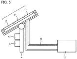
- Fig. 5 is a schematic diagram showing the general configuration of a variation of the hydrogen generation system according to the first embodiment.
- heat exhauster mechanism 3 includes flow path 12ba and pipe 33 but does not include heat exchanger 31.
- Flow path 12ba is connected to pipe 33.
- Such a configuration may be used for heat exhauster mechanism 3 to raise the temperature of water 21a using the heat generated in concentrator photovoltaic module 11.
- heat exhauster mechanism 3 cools concentrator photovoltaic module 11 and raises the temperature of water 21a stored in hydrogen generation apparatus 2 using the heat generated in concentrator photovoltaic module 11. Therefore, the hydrogen generation system according to the first embodiment improves the efficiency of concentrator photovoltaic module 11 and hydrogen generation apparatus 2 regardless of the outside air temperature.
- heat exhauster mechanism 3 includes heat exchanger 31
- water 21a stored in hydrogen generation apparatus 2 does not flow into flow path 12ba in concentrator photovoltaic module 11. Therefore, flow path 12ba can be prevented from being corroded by an additive in water 21a.
- heat exhauster mechanism 3 includes flow path 12ba and pipe 33 but does not include heat exchanger 31, the temperature of water 21a is raised by the heat generated in concentrator photovoltaic module 11. In this case, therefore, the temperature of water 21a in hydrogen generation apparatus 2 can be raised more efficiently. Further, in this case, the configuration of the hydrogen generation system can be simplified.
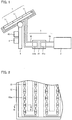
- Fig. 6 is a schematic diagram showing the general configuration of a hydrogen generation system according to the second embodiment.
- the hydrogen generation system according to the second embodiment includes concentrator photovoltaic apparatus 1, hydrogen generation apparatus 2, and heat exhauster mechanism 3.
- Concentrator photovoltaic apparatus 1 is attached to stand 4, and stand 4 includes driver 41 (not shown), solar azimuth sensor 42 (not shown), and tracking control board 43. Between concentrator photovoltaic apparatus 1 and hydrogen generation apparatus 2, voltage conversion unit 5 is provided.
- Heat exhauster mechanism 3 includes flow path 12ba (see Fig. 7 ), heat exchanger 31, pipe 32, and pipe 33. Heat exhauster mechanism 3 may only include flow path 12ba and pipe 33, but without heat exchanger 31.
- Fig. 7 is an enlarged cross-sectional view of concentrator photovoltaic module 11 in the hydrogen generation system according to the second embodiment.
- casing 12 includes frame 12a, bottom plate 12b, and top plate 12c.
- Frame 12a and bottom plate 12b are preferably made of the same material.
- Frame 12a and bottom plate 12b are preferably made of a resin material.
- Frame 12a and bottom plate 12b are preferably integrally formed.
- flow path 12ba is provided on bottom plate 12b.
- flow path 12ba is defined by a tubular member 18.
- Tubular member 18 is provided on bottom plate 12b.
- Tubular member 18 is made of Al, Cu or the like.
- Flow path 12ba is connected to heat exchanger 31 via pipe 32.
- Heat exchanger 31 is connected to storage tank 21 of hydrogen generation apparatus 2 via pipe 32. If heat exhauster mechanism 3 does not include heat exchanger 31, flow path 12ba is connected to storage tank 21 of hydrogen generation apparatus 2 via pipe 33.
- Concentrator photovoltaic element 13 is provided over tubular member 18. Between concentrator photovoltaic element 13 and tubular member 18, insulating material 14 and wiring material 15 are provided. Insulating material 14 is provided on tubular member 18. Wiring material 15 is provided on insulating material 14. Concentrator photovoltaic element 13 is electrically connected to wiring material 15.
- the hydrogen generation system according to the second embodiment provides an improved efficiency of the hydrogen generation system regardless of the outside air temperature.
- bottom plate 12b exhausts the heat from concentrator photovoltaic module 11. It is therefore not necessary for bottom plate 12b to be made of a high-thermal-conductivity material.
- Bottom plate 12b may be made of the same material as frame 12a, i.e., a resin material, and they can be integrally formed. If bottom plate 12b and frame 12a are integrally formed of a resin material, the concentrator photovoltaic module can be manufactured in a simplified process and can be reduced in weight.
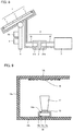
- Fig. 8 is a schematic diagram showing the general configuration of the hydrogen generation system according to the third embodiment.
- the hydrogen generation system according to the third embodiment includes concentrator photovoltaic apparatus 1, hydrogen generation apparatus 2, and heat exhauster mechanism 3.
- Concentrator photovoltaic apparatus 1 is attached to stand 4, and stand 4 includes driver 41 (not shown), solar azimuth sensor 42 (not shown), and tracking control board 43. Between concentrator photovoltaic apparatus 1 and hydrogen generation apparatus 2, voltage conversion unit 5 is provided.
- Heat exhauster mechanism 3 includes flow path 12ba (see Fig. 9 ), heat exchanger 31, pipe 32, and pipe 33. Heat exhauster mechanism 3 may only include flow path 12ba and pipe 33, but without heat exchanger 31.
- Fig. 9 is an enlarged cross-sectional view of concentrator photovoltaic module 11 in the hydrogen generation system according to the third embodiment.
- casing 12 includes frame 12a, bottom plate 12b, and top plate 12c.
- Frame 12a and bottom plate 12b are preferably made of the same material.
- Frame 12a and bottom plate 12b are preferably made of a resin material.
- Frame 12a and bottom plate 12b are preferably integrally formed.
- flow path 12ba is provided on bottom plate 12b.
- flow path 12ba is defined by tubular member 18.
- Tubular member 18 is provided on bottom plate 12b.
- Tubular member 18 is made of Al, Cu or the like.
- Flow path 12ba is connected to heat exchanger 31 by connecting tubular member 18 and pipe 32 to each other.
- Heat exchanger 31 is connected to storage tank 21 of hydrogen generation apparatus 2 by connecting to pipe 32.
- pipe 32 is made of an insulating material for insulation. If heat exhauster mechanism 3 does not include heat exchanger 31, flow path 12ba is connected to storage tank 21 of hydrogen generation apparatus 2 by connecting tubular member 18 and pipe 33 to each other.
- pipe 33 is made of an insulating material for insulation.
- Tubular member 18 is divided into a first portion 18a and a second portion 18b.
- One side of tubular member 18 in the extending direction is first portion 18a, and the other side of tubular member 18 in the extending direction is second portion 18b.
- An insulating portion 18c is interposed between first portion 18a and second portion 18b.
- Insulating portion 18c is made of, for example, butyl rubber.
- Concentrator photovoltaic element 13 is provided on tubular member 18. Concentrator photovoltaic element 13 is electrically connected to tubular member 18. For example, the anode of concentrator photovoltaic element 13 is electrically connected to first portion 18a, and the cathode of concentrator photovoltaic element 13 is electrically connected to second portion 18b. Between concentrator photovoltaic element 13 and tubular member 18, insulating material 14 and wiring material 15 are not provided. In other words, concentrator photovoltaic element 13 is provided directly on tubular member 18.
- the hydrogen generation system according to the second embodiment provides an improved efficiency of the hydrogen generation system regardless of the outside air temperature.
- the hydrogen generation system according to the third embodiment eliminates the need for insulating material 14 and wiring material 15. Therefore, the hydrogen generation system according to the third embodiment can reduce the manufacturing cost. Further, since insulating material 14 is not provided between concentrator photovoltaic element 13 and tubular member 18 in the hydrogen generation system according to the third embodiment, the heat generated from concentrator photovoltaic element 13 can be exhausted more efficiently.
- Fig. 10 is a schematic diagram showing the general configuration of the hydrogen generation system according to the fourth embodiment.
- the hydrogen generation system according to the second embodiment includes concentrator photovoltaic apparatus 1, hydrogen generation apparatus 2, and heat exhauster mechanism 3.
- Heat exhauster mechanism 3 includes flow path 12ba (not shown), pipe 32 connected to flow path 12ba, heat exchanger 31 connected to pipe 32, and pipe 33 connected to heat exchanger 31.
- Heat exhauster mechanism 3 may only include flow path 12ba (not shown) and pipe 33 connected to flow path 12ba, but without pipe 32 and heat exchanger 31.
- Concentrator photovoltaic apparatus 1 is attached to stand 4, and stand 4 includes driver 41 (not shown), solar azimuth sensor 42 (not shown), and tracking control board 43. Between concentrator photovoltaic apparatus 1 and hydrogen generation apparatus 2, voltage conversion unit 5 is provided.
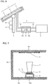
- Fig. 11 is a schematic top view of tracking control board 43.
- tracking control board 43 includes a control unit 43a, a power supply unit 43b, a terminal unit 43c, and a first pipe 43d.
- Control unit 43a is a part to control driver 41 based on the signal from solar azimuth sensor 42.
- Power supply unit 43b is a part to convert AC power supply into DC power supply for control, for example.
- Terminal unit 43c is a part having various types of terminals for connecting to external elements.
- First pipe 43d is provided in tracking control board 43.
- power supply unit 43b generates the largest amount of heat. Therefore, first pipe 43d is provided preferably around power supply unit 43b. Specifically, first pipe 43d is provided preferably on the casing of power supply unit 43b.
- First pipe 43d is made of Al, Cu or the like.
- voltage conversion unit 5 is, for example, a DCDC converter.
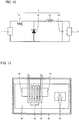
- Fig. 12 is a circuit diagram of voltage conversion unit 5. As shown in Fig. 12 , voltage conversion unit 5 includes a switching element 51, a diode 52, a coil element 53, and a capacitor element 54. Switching element 51 is, for example, a power metal oxide semiconductor field effect transistor (MOSFET).
- MOSFET power metal oxide semiconductor field effect transistor
- Fig. 13 is a schematic top view of voltage conversion unit 5.
- voltage conversion unit 5 includes a casing 55, a substrate 56, and a second pipe 57.
- Switching element 51, diode 52, coil element 53, and capacitor element 54 are mounted on substrate 56.
- Substrate 56 is contained in casing 55.
- Second pipe 57 is provided in casing 55.
- Second pipe 57 is provided preferably around switching element 51, diode 52, and coil element 53. Second pipe 57 is made of Al, Cu or the like.
- First pipe 43d and second pipe 57 are connected to flow path 12ba. Specifically, first pipe 43d and second pipe 57 are disposed on the path of pipe 32. If heat exhauster mechanism 3 does not include pipe 32 and heat exchanger 31, first pipe 43d and second pipe 57 are disposed on the path of pipe 33 and thus connected to flow path 12ba.
- the hydrogen generation system according to the fourth embodiment can raise the temperature of water 21a in hydrogen generation apparatus 2 using not only the heat generated in concentrator photovoltaic module 11 but also the heat generated in tracking control board 43 and voltage conversion unit 5. Therefore, the hydrogen generation system according to the fourth embodiment can use the exhaust heat from the hydrogen generation system more efficiently.
Landscapes
- Chemical & Material Sciences (AREA)
- Engineering & Computer Science (AREA)
- Metallurgy (AREA)
- Chemical Kinetics & Catalysis (AREA)
- Electrochemistry (AREA)
- Materials Engineering (AREA)
- Organic Chemistry (AREA)
- Automation & Control Theory (AREA)
- Inorganic Chemistry (AREA)
- Life Sciences & Earth Sciences (AREA)
- Sustainable Development (AREA)
- Electrolytic Production Of Non-Metals, Compounds, Apparatuses Therefor (AREA)
- Photovoltaic Devices (AREA)
- Hydrogen, Water And Hydrids (AREA)
Abstract
Description
- The present disclosure relates to a hydrogen generation system. The present application claims a priority based on Japanese Patent Application No.
2016-147349 - As described in Japanese Patent Laying-Open No.
2012-94684 - The system described in
PTL 1 includes a concentrator photovoltaic module, and a hydrogen generation apparatus that electrolyzes water with electric power supplied from the concentrator photovoltaic module and generates hydrogen. - PTL 1: Japanese Patent Laying-Open No.
2012-94684 - A hydrogen generation system according to one aspect of the present disclosure comprises: a concentrator photovoltaic module including: a casing including a frame, and a bottom plate provided at the lower end of the frame, and a concentrator photovoltaic element disposed on the bottom plate; a hydrogen generation apparatus configured to generate hydrogen by electrolyzing water with electric power supplied from the concentrator photovoltaic module; and a heat exhauster mechanism configured to raise the temperature of the water using heat generated in the concentrator photovoltaic module.
-
-
Fig. 1 is a schematic diagram showing the general configuration of a hydrogen generation system according to a first embodiment. -
Fig. 2 is a top view of a concentratorphotovoltaic apparatus 1. -
Fig. 3 is an enlarged cross-sectional view of a concentratorphotovoltaic module 11. -
Fig. 4 is a schematic diagram showing the configuration of ahydrogen generation apparatus 2. -
Fig. 5 is a schematic diagram showing the general configuration of a variation of the hydrogen generation system according to the first embodiment. -
Fig. 6 is a schematic diagram showing the general configuration of a hydrogen generation system according to a second embodiment. -
Fig. 7 is an enlarged cross-sectional view of concentratorphotovoltaic module 11 in the hydrogen generation system according to the second embodiment. -
Fig. 8 is a schematic diagram showing the general configuration of a hydrogen generation system according to a third embodiment. -
Fig. 9 is an enlarged cross-sectional view of concentratorphotovoltaic module 11 in the hydrogen generation system according to the third embodiment. -
Fig. 10 is a schematic diagram showing the general configuration of a hydrogen generation system according to a fourth embodiment. -
Fig. 11 is a schematic top view of atracking control board 43. -
Fig. 12 is a circuit diagram of avoltage conversion unit 5. -
Fig. 13 is a schematic top view ofvoltage conversion unit 5. - A concentrator photovoltaic element included in a concentrator photovoltaic module has a lower power generation efficiency as the temperature rises. When the outside air temperature is high, the heat generated in the concentrator photovoltaic module is not sufficiently dissipated. This causes a temperature rise of the concentrator photovoltaic element, thus lowering the power generation efficiency of the concentrator photovoltaic module.
- It is known that, when water to be electrolyzed has a lower temperature, a hydrogen generation apparatus has a lower efficiency in hydrogen generation. Therefore, when the outside air temperature is low, the hydrogen generation apparatus has a low efficiency in hydrogen generation. Thus, the system described in
PTL 1 cannot operate efficiently whether the outside air temperature is high or low. - The present disclosure has been made in view of such problems of the prior art. Specifically, the present disclosure provides a hydrogen generation system that can generate hydrogen efficiently regardless of the outside air temperature.
- According the above, it is possible to generate hydrogen efficiently regardless of the outside air temperature.
- First, embodiments of the present disclosure are enumerated.
- (1) A hydrogen generation system according to one aspect of the present disclosure comprises: a concentrator photovoltaic module including: a casing including a frame, and a bottom plate provided at the lower end of the frame, and a concentrator photovoltaic element disposed on the bottom plate; a hydrogen generation apparatus configured to generate hydrogen by electrolyzing water with electric power supplied from the concentrator photovoltaic module; and a heat exhauster mechanism configured to raise the temperature of the water using heat generated in the concentrator photovoltaic module.
The hydrogen generation system of (1) can generate hydrogen efficiently regardless of the outside air temperature. - (2) In the hydrogen generation system of (1), the heat exhauster mechanism may include: a heat exchanger, and a flow path provided in the bottom plate and connected to the heat exchanger, so that coolant flows in the flow path. The heat exchanger may raise the temperature of the water through the coolant.
The hydrogen generation system of (2) can prevent the water from polluting the flow path in the heat exhauster mechanism. - (3) In the hydrogen generation system of (1), the heat exhauster mechanism may include a flow path provided in the bottom plate, so that the water flows in the flow path.
The hydrogen generation system of (3) can raise the temperature of the water without using a heat exchanger. That is, the system configuration can be simplified. - (4) In the hydrogen generation system of (2) or (3), the flow path may be disposed under the concentrator photovoltaic element.
The hydrogen generation system of (4) can cool the concentrator photovoltaic element efficiently. - (5) In the hydrogen generation system of (1), the heat exhauster mechanism may include: a heat exchanger, and a flow path provided on the bottom plate and connected to the heat exchanger, so that coolant flows in the flow path. The heat exchanger may raise the temperature of the water through the coolant. The concentrator photovoltaic element may be disposed over the flow path.
The hydrogen generation system of (5) can cool the concentrator photovoltaic element efficiently. - (6) In the hydrogen generation system of (5), the frame and the bottom plate may be integrally formed of a resin material.
The hydrogen generation system of (6) allows easy manufacture of the concentrator photovoltaic module and can reduce the weight of the concentrator photovoltaic module. - (7) In the hydrogen generation system of (5) or (6), the flow path and the concentrator photovoltaic element may be electrically connected to each other.
The hydrogen generation system of (7) eliminates the need for providing separate wiring for connecting the concentrator photovoltaic element. - (8) The hydrogen generation system of (2) to (7) may further comprise a tracking control board configured to control the concentrator photovoltaic module to track the sun, the tracking control board including a first pipe in the tracking control board. The first pipe may be connected to the flow path.
The hydrogen generation system of (8) can use the heat exhaust from the system more efficiently. - (9) The hydrogen generation system of (2) to (8) may further comprise a voltage conversion unit configured to convert a voltage supplied from the concentrator photovoltaic module, the voltage conversion unit including a second pipe in the voltage conversion unit. The second pipe may be connected to the flow path.
- The hydrogen generation system of (9) can use the heat exhaust from the system more efficiently.
- The details of embodiments of the present disclosure are hereinafter described with reference to the drawings. In the drawings, identical or corresponding parts are identically denoted. The embodiments hereinafter described may be combined at least partially in any way.
- The configuration of a hydrogen generation system according to the first embodiment is hereinafter described.
-
Fig. 1 is a schematic diagram showing the general configuration of the hydrogen generation system according to the first embodiment. As shown inFig. 1 , the hydrogen generation system according to the first embodiment includes a concentratorphotovoltaic apparatus 1, ahydrogen generation apparatus 2, and aheat exhauster mechanism 3. Concentratorphotovoltaic apparatus 1 includes a plurality of concentratorphotovoltaic modules 11. - Concentrator
photovoltaic apparatus 1 is attached to astand 4.Stand 4 includes a driver 41 (not shown), a solar azimuth sensor 42 (not shown), and atracking control board 43. - Driver 41 changes the orientation of the light receiving surface of concentrator
photovoltaic apparatus 1. Specifically, driver 41 includes a power source, such as an electric motor. Solar azimuth sensor 42 outputs a signal representing the direction of the sun. Specifically, solar azimuth sensor 42 includes a sensor for detecting the direction of the sun.Tracking control board 43 controls driver 41 based on the signal from solar azimuth sensor 42. Specifically, trackingcontrol board 43 controls the power source, such as an electric motor, included in driver 41 so that the light receiving surface faces toward the sun. -
Fig. 2 is a top view of concentratorphotovoltaic apparatus 1. As shown inFig. 2 , each concentratorphotovoltaic module 11 includes acasing 12 and concentratorphotovoltaic elements 13. A plurality of concentratorphotovoltaic elements 13 are arranged in each concentratorphotovoltaic module 11. A plurality of concentratorphotovoltaic elements 13 are arranged in a matrix. -
Fig. 3 is an enlarged cross-sectional view of concentratorphotovoltaic module 11. As shown inFig. 3 , casing 12 includes aframe 12a, abottom plate 12b, and atop plate 12c.Frame 12a forms the side wall ofcasing 12.Frame 12a is made of, for example, a resin material. The resin material forframe 12a is, for example, polybutylene terephthalate (PBT) with glass fiber contained. -
Bottom plate 12b forms the bottom face ofcasing 12.Bottom plate 12b is provided at the lower end offrame 12a.Bottom plate 12b includes a flow path 12ba therein. Specifically,bottom plate 12b has an upper bottom plate 12bb and a lower bottom plate 12bc. Upper bottom plate 12bb has a groove 12bd. Upper bottom plate 12bb is arranged so that its surface having groove 12bd aligns with lower bottom plate 12bc. Upper bottom plate 12bb and lower bottom plate 12bc are bonded to each other with a brazing material 12be. Thus, flow path 12ba is formed inbottom plate 12b. Flow path 12ba constitutes a part ofheat exhauster mechanism 3. Coolant flows in flow path 12ba. The coolant is a liquid or a gas. -
Bottom plate 12b is made of a material higher in thermal conductivity thanframe 12a. For example, ifframe 12a is made of a resin material,bottom plate 12b is made of metallic material. The metallic material forbottom plate 12b is, for example, copper (Cu) or aluminum (Al). - Concentrator
photovoltaic element 13 is provided overbottom plate 12b. Betweenbottom plate 12b and concentratorphotovoltaic element 13, an insulatingmaterial 14 and awiring material 15 are provided. Insulatingmaterial 14 is provided onbottom plate 12b.Wiring material 15 is provided on insulatingmaterial 14.Wiring material 15 is electrically connected to concentratorphotovoltaic element 13. Insulatingmaterial 14 is made of, for example, polyimide.Wiring material 15 is made of, for example, Cu. Insulatingmaterial 14 andwiring material 15 constitute, for example, a flexible printed circuit (FPC) board. - As shown in
Fig. 2 andFig. 3 , concentratorphotovoltaic element 13 is preferably disposed over flow path 12ba. That is, concentratorphotovoltaic element 13 preferably coincides in position with flow path 12ba in plan view (as seen from the direction orthogonal tobottom plate 12b). - As shown in
Fig. 3 ,top plate 12c forms the top face ofcasing 12.Top plate 12c is provided at the upper end offrame 12a. The upper end offrame 12a is the end opposite to the lower end offrame 12a at whichbottom plate 12b is disposed. - A primary
optical system 16 is provided attop plate 12c. Primaryoptical system 16 is, for example, a Fresnel lens. A secondaryoptical system 17 is provided on concentratorphotovoltaic element 13. Secondaryoptical system 17 is, for example, a rod lens. Secondaryoptical system 17 may be a sphere lens or the like. The sunlight is condensed by primaryoptical system 16 and enters secondaryoptical system 17. The sunlight that has entered secondaryoptical system 17 is transmitted to concentratorphotovoltaic element 13. - Concentrator
photovoltaic element 13 generates electric power by receiving the transmitted sunlight. The electric power generated by concentratorphotovoltaic element 13 is supplied tohydrogen generation apparatus 2. As shown inFig. 1 , the hydrogen generation system according to the first embodiment may includevoltage conversion unit 5.Voltage conversion unit 5 is, for example, a DCDC converter.Voltage conversion unit 5 performs voltage conversion for the electric power supplied from concentratorphotovoltaic apparatus 1. -
Fig. 4 is a schematic diagram showing the configuration ofhydrogen generation apparatus 2. As shown inFig. 4 ,hydrogen generation apparatus 2 includes astorage tank 21, ananode 22, acathode 23, and a partition 24.Storage tank 21 has apipe 33 connected thereto.Storage tank 21stores water 21a to be electrolyzed. An additive, such as sodium hydroxide, is added towater 21a for facilitating the electrolysis. The additive inwater 21a may be sodium carbonate, sodium sulfate, potassium hydroxide or the like.Water 21a, however, may be pure water, for example. -
Anode 22 andcathode 23 are connected to concentrator photovoltaic apparatus 1 (or voltage conversion unit 5).Anode 22 andcathode 23electrolyze water 21a with electric power supplied from concentratorphotovoltaic apparatus 1. As a result,hydrogen 21b is generated atanode 22, andoxygen 21c is generated atcathode 23. -
Heat exhauster mechanism 3 raises the temperature ofwater 21a stored inhydrogen generation apparatus 2 using the heat generated inphotovoltaic module 11. Specifically, as shown inFig. 1 ,heat exhauster mechanism 3 includes a flow path 12ba (not shown inFig. 1 ), aheat exchanger 31, apipe 32, and apipe 33. -
Heat exchanger 31 includes an inlet-side pipe 31a and an outlet-side pipe 31b. Inlet-side pipe 31a is connected to flow path 12ba. Inlet-side pipe 31a and flow path 12ba are connected to each other viapipe 32. Outlet-side pipe 31b is connected tostorage tank 21 ofhydrogen generation apparatus 2. Outlet-side pipe 31b andstorage tank 21 are connected to each other viapipe 33.Heat exchanger 31 exchanges heat between the coolant flowing through inlet-side pipe 31a andwater 21a flowing through outlet-side pipe 31b. Thus,heat exhauster mechanism 3 raises the temperature ofwater 21a using the heat generated inphotovoltaic module 11. -
Fig. 5 is a schematic diagram showing the general configuration of a variation of the hydrogen generation system according to the first embodiment. As shown inFig. 5 ,heat exhauster mechanism 3 includes flow path 12ba andpipe 33 but does not includeheat exchanger 31. Flow path 12ba is connected topipe 33. In this case, whenwater 21a passes through flow path 12ba, the temperature ofwater 21a is raised by the heat generated inphotovoltaic module 11. Such a configuration may be used forheat exhauster mechanism 3 to raise the temperature ofwater 21a using the heat generated in concentratorphotovoltaic module 11. - The advantageous effects of the hydrogen generation system according to the first embodiment are hereinafter described.
- In the hydrogen generation system according to the first embodiment,
heat exhauster mechanism 3 cools concentratorphotovoltaic module 11 and raises the temperature ofwater 21a stored inhydrogen generation apparatus 2 using the heat generated in concentratorphotovoltaic module 11. Therefore, the hydrogen generation system according to the first embodiment improves the efficiency of concentratorphotovoltaic module 11 andhydrogen generation apparatus 2 regardless of the outside air temperature. - In the hydrogen generation system according to the first embodiment, if
heat exhauster mechanism 3 includesheat exchanger 31,water 21a stored inhydrogen generation apparatus 2 does not flow into flow path 12ba in concentratorphotovoltaic module 11. Therefore, flow path 12ba can be prevented from being corroded by an additive inwater 21a. - In the hydrogen generation system according to the first embodiment, if
heat exhauster mechanism 3 includes flow path 12ba andpipe 33 but does not includeheat exchanger 31, the temperature ofwater 21a is raised by the heat generated in concentratorphotovoltaic module 11. In this case, therefore, the temperature ofwater 21a inhydrogen generation apparatus 2 can be raised more efficiently. Further, in this case, the configuration of the hydrogen generation system can be simplified. - In the hydrogen generation system according to the first embodiment, if flow path 12ba coincides in position with concentrator
photovoltaic element 13 in plan view, the heat generated in concentratorphotovoltaic module 12 can be efficiently transferred toheat exhauster mechanism 3. In this case, therefore, the efficiency of the hydrogen generation system is further improved. - The configuration of a hydrogen generation system according to the second embodiment is hereinafter described.
- The following mainly describes the differences from the hydrogen generation system according to the first embodiment, and the redundant description will not be repeated.
-
Fig. 6 is a schematic diagram showing the general configuration of a hydrogen generation system according to the second embodiment. As shown inFig. 6 , the hydrogen generation system according to the second embodiment includes concentratorphotovoltaic apparatus 1,hydrogen generation apparatus 2, andheat exhauster mechanism 3. Concentratorphotovoltaic apparatus 1 is attached to stand 4, and stand 4 includes driver 41 (not shown), solar azimuth sensor 42 (not shown), and trackingcontrol board 43. Between concentratorphotovoltaic apparatus 1 andhydrogen generation apparatus 2,voltage conversion unit 5 is provided. -
Heat exhauster mechanism 3 includes flow path 12ba (seeFig. 7 ),heat exchanger 31,pipe 32, andpipe 33.Heat exhauster mechanism 3 may only include flow path 12ba andpipe 33, but withoutheat exchanger 31. -
Fig. 7 is an enlarged cross-sectional view of concentratorphotovoltaic module 11 in the hydrogen generation system according to the second embodiment. As shown inFig. 7 , casing 12 includesframe 12a,bottom plate 12b, andtop plate 12c.Frame 12a andbottom plate 12b are preferably made of the same material.Frame 12a andbottom plate 12b are preferably made of a resin material.Frame 12a andbottom plate 12b are preferably integrally formed. - On
bottom plate 12b, flow path 12ba is provided. Specifically, flow path 12ba is defined by atubular member 18.Tubular member 18 is provided onbottom plate 12b.Tubular member 18 is made of Al, Cu or the like. Flow path 12ba is connected toheat exchanger 31 viapipe 32.Heat exchanger 31 is connected tostorage tank 21 ofhydrogen generation apparatus 2 viapipe 32. Ifheat exhauster mechanism 3 does not includeheat exchanger 31, flow path 12ba is connected tostorage tank 21 ofhydrogen generation apparatus 2 viapipe 33. - Concentrator
photovoltaic element 13 is provided overtubular member 18. Between concentratorphotovoltaic element 13 andtubular member 18, insulatingmaterial 14 andwiring material 15 are provided. Insulatingmaterial 14 is provided ontubular member 18.Wiring material 15 is provided on insulatingmaterial 14. Concentratorphotovoltaic element 13 is electrically connected to wiringmaterial 15. - The advantageous effects of the hydrogen generation system according to the second embodiment are hereinafter described.
- The hydrogen generation system according to the second embodiment provides an improved efficiency of the hydrogen generation system regardless of the outside air temperature.
- In the hydrogen generation system according to the second embodiment, flow path 12ba provided on
bottom plate 12b exhausts the heat from concentratorphotovoltaic module 11. It is therefore not necessary forbottom plate 12b to be made of a high-thermal-conductivity material.Bottom plate 12b may be made of the same material asframe 12a, i.e., a resin material, and they can be integrally formed. Ifbottom plate 12b andframe 12a are integrally formed of a resin material, the concentrator photovoltaic module can be manufactured in a simplified process and can be reduced in weight. - The configuration of a hydrogen generation system according to the third embodiment is hereinafter described.
- The following describes the differences from the hydrogen generation system according to the second embodiment, and the redundant description will not be repeated.
-
Fig. 8 is a schematic diagram showing the general configuration of the hydrogen generation system according to the third embodiment. As shown inFig. 8 , the hydrogen generation system according to the third embodiment includes concentratorphotovoltaic apparatus 1,hydrogen generation apparatus 2, andheat exhauster mechanism 3. Concentratorphotovoltaic apparatus 1 is attached to stand 4, and stand 4 includes driver 41 (not shown), solar azimuth sensor 42 (not shown), and trackingcontrol board 43. Between concentratorphotovoltaic apparatus 1 andhydrogen generation apparatus 2,voltage conversion unit 5 is provided. -
Heat exhauster mechanism 3 includes flow path 12ba (seeFig. 9 ),heat exchanger 31,pipe 32, andpipe 33.Heat exhauster mechanism 3 may only include flow path 12ba andpipe 33, but withoutheat exchanger 31. -
Fig. 9 is an enlarged cross-sectional view of concentratorphotovoltaic module 11 in the hydrogen generation system according to the third embodiment. As shown inFig. 9 , casing 12 includesframe 12a,bottom plate 12b, andtop plate 12c.Frame 12a andbottom plate 12b are preferably made of the same material.Frame 12a andbottom plate 12b are preferably made of a resin material.Frame 12a andbottom plate 12b are preferably integrally formed. - On
bottom plate 12b, flow path 12ba is provided. Specifically, flow path 12ba is defined bytubular member 18.Tubular member 18 is provided onbottom plate 12b.Tubular member 18 is made of Al, Cu or the like. Flow path 12ba is connected toheat exchanger 31 by connectingtubular member 18 andpipe 32 to each other.Heat exchanger 31 is connected tostorage tank 21 ofhydrogen generation apparatus 2 by connecting topipe 32. In this case,pipe 32 is made of an insulating material for insulation. Ifheat exhauster mechanism 3 does not includeheat exchanger 31, flow path 12ba is connected tostorage tank 21 ofhydrogen generation apparatus 2 by connectingtubular member 18 andpipe 33 to each other. In this case,pipe 33 is made of an insulating material for insulation. -
Tubular member 18 is divided into afirst portion 18a and asecond portion 18b. One side oftubular member 18 in the extending direction isfirst portion 18a, and the other side oftubular member 18 in the extending direction issecond portion 18b. An insulatingportion 18c is interposed betweenfirst portion 18a andsecond portion 18b. Insulatingportion 18c is made of, for example, butyl rubber. - Concentrator
photovoltaic element 13 is provided ontubular member 18. Concentratorphotovoltaic element 13 is electrically connected totubular member 18. For example, the anode of concentratorphotovoltaic element 13 is electrically connected tofirst portion 18a, and the cathode of concentratorphotovoltaic element 13 is electrically connected tosecond portion 18b. Between concentratorphotovoltaic element 13 andtubular member 18, insulatingmaterial 14 andwiring material 15 are not provided. In other words, concentratorphotovoltaic element 13 is provided directly ontubular member 18. - The advantageous effects of the hydrogen generation system according to the third embodiment are hereinafter described.
- The hydrogen generation system according to the second embodiment provides an improved efficiency of the hydrogen generation system regardless of the outside air temperature.
- Further, the hydrogen generation system according to the third embodiment eliminates the need for insulating
material 14 andwiring material 15. Therefore, the hydrogen generation system according to the third embodiment can reduce the manufacturing cost. Further, since insulatingmaterial 14 is not provided between concentratorphotovoltaic element 13 andtubular member 18 in the hydrogen generation system according to the third embodiment, the heat generated from concentratorphotovoltaic element 13 can be exhausted more efficiently. - The configuration of a hydrogen generation system according to the fourth embodiment is hereinafter described.
- The following describes the differences from the hydrogen generation systems according to the first to third embodiments, and the redundant description will not be repeated.
-
Fig. 10 is a schematic diagram showing the general configuration of the hydrogen generation system according to the fourth embodiment. As shown inFig. 10 , the hydrogen generation system according to the second embodiment includes concentratorphotovoltaic apparatus 1,hydrogen generation apparatus 2, andheat exhauster mechanism 3.Heat exhauster mechanism 3 includes flow path 12ba (not shown),pipe 32 connected to flow path 12ba,heat exchanger 31 connected topipe 32, andpipe 33 connected toheat exchanger 31.Heat exhauster mechanism 3 may only include flow path 12ba (not shown) andpipe 33 connected to flow path 12ba, but withoutpipe 32 andheat exchanger 31. - Concentrator
photovoltaic apparatus 1 is attached to stand 4, and stand 4 includes driver 41 (not shown), solar azimuth sensor 42 (not shown), and trackingcontrol board 43. Between concentratorphotovoltaic apparatus 1 andhydrogen generation apparatus 2,voltage conversion unit 5 is provided. -
Fig. 11 is a schematic top view of trackingcontrol board 43. As shown inFig. 11 , trackingcontrol board 43 includes acontrol unit 43a, apower supply unit 43b, aterminal unit 43c, and afirst pipe 43d.Control unit 43a is a part to control driver 41 based on the signal from solar azimuth sensor 42.Power supply unit 43b is a part to convert AC power supply into DC power supply for control, for example.Terminal unit 43c is a part having various types of terminals for connecting to external elements. -
First pipe 43d is provided in trackingcontrol board 43. In trackingcontrol board 43,power supply unit 43b generates the largest amount of heat. Therefore,first pipe 43d is provided preferably aroundpower supply unit 43b. Specifically,first pipe 43d is provided preferably on the casing ofpower supply unit 43b.First pipe 43d is made of Al, Cu or the like. - As described above,
voltage conversion unit 5 is, for example, a DCDC converter.Fig. 12 is a circuit diagram ofvoltage conversion unit 5. As shown inFig. 12 ,voltage conversion unit 5 includes a switchingelement 51, adiode 52, acoil element 53, and acapacitor element 54. Switchingelement 51 is, for example, a power metal oxide semiconductor field effect transistor (MOSFET). -
Fig. 13 is a schematic top view ofvoltage conversion unit 5. As shown inFig. 13 ,voltage conversion unit 5 includes acasing 55, asubstrate 56, and asecond pipe 57. Switchingelement 51,diode 52,coil element 53, andcapacitor element 54 are mounted onsubstrate 56.Substrate 56 is contained incasing 55.Second pipe 57 is provided incasing 55. - Switching
element 51,diode 52, andcoil element 53 generate a large amount of heat involtage conversion unit 5. Therefore,second pipe 57 is provided preferably around switchingelement 51,diode 52, andcoil element 53.Second pipe 57 is made of Al, Cu or the like. -
First pipe 43d andsecond pipe 57 are connected to flow path 12ba. Specifically,first pipe 43d andsecond pipe 57 are disposed on the path ofpipe 32. Ifheat exhauster mechanism 3 does not includepipe 32 andheat exchanger 31,first pipe 43d andsecond pipe 57 are disposed on the path ofpipe 33 and thus connected to flow path 12ba. - The advantageous effects of the hydrogen generation system according to the fourth embodiment are hereinafter described.
- The hydrogen generation system according to the fourth embodiment can raise the temperature of
water 21a inhydrogen generation apparatus 2 using not only the heat generated in concentratorphotovoltaic module 11 but also the heat generated in trackingcontrol board 43 andvoltage conversion unit 5. Therefore, the hydrogen generation system according to the fourth embodiment can use the exhaust heat from the hydrogen generation system more efficiently. - The embodiments disclosed herein should be construed as being by way of illustration in every respect, not by way of limitation. The scope of the present invention is defined not by the above-described embodiments but by the terms of the claims. It is intended that the scope of the present invention includes any modification within the meaning and the scope equivalent to the terms of the claims.
- 1: concentrator photovoltaic apparatus; 2: hydrogen generation apparatus; 3: heat exhauster mechanism; 4: stand; 5: voltage conversion unit; 11: concentrator photovoltaic module; 12: casing; 12a: frame; 12b: bottom plate; 12ba: flow path; 12bb: upper bottom plate; 12bc: lower bottom plate; 12bd: groove; 12be: brazing material; 12c: top plate; 13: concentrator photovoltaic element; 14: insulating material; 15: wiring material; 16: primary optical system; 17:secondary optical system; 18: tubular member; 18a: first portion; 18b: second portion; 18c: insulating portion; 21: storage tank; 21a:
water 21b: hydrogen; 21c: oxygen; 22: anode; 23: cathode; 24: partition; 31: heat exchanger; 31a: inlet-side pipe; 31b: outlet-side pipe; 32, 33: pipe; 41: driver; 42: solar azimuth sensor; 43: tracking control board; 43a: control unit; 43b: power supply unit; 43c: terminal unit; 43d: first pipe; 51: switching element; 52: diode; 53: coil element; 54: capacitor element; 55: casing; 56: substrate; 57: second pipe
Claims (9)
- A hydrogen generation system comprising:a concentrator photovoltaic module including:a casing including a frame, and a bottom plate provided at a lower end of the frame, anda concentrator photovoltaic element disposed on the bottom plate;a hydrogen generation apparatus configured to generate hydrogen by electrolyzing water with electric power supplied from the concentrator photovoltaic module; anda heat exhauster mechanism configured to raise a temperature of the water using heat generated in the concentrator photovoltaic module.
- The hydrogen generation system according to claim 1, wherein
the heat exhauster mechanism includes:a heat exchanger, anda flow path provided in the bottom plate and connected to the heat exchanger, so that coolant flows in the flow path, andthe heat exchanger raises the temperature of the water through the coolant. - The hydrogen generation system according to claim 1, wherein the heat exhauster mechanism includes a flow path provided in the bottom plate, so that the water flows in the flow path.
- The hydrogen generation system according to claim 2 or 3, wherein the flow path is disposed under the concentrator photovoltaic element.
- The hydrogen generation system according to claim 1, wherein
the heat exhauster mechanism includes:a heat exchanger, anda flow path provided on the bottom plate and connected to the heat exchanger, so that coolant flows in the flow path,the heat exchanger raises the temperature of the water through the coolant, and
the concentrator photovoltaic element is disposed over the flow path. - The hydrogen generation system according to claim 5, wherein the frame and the bottom plate are integrally formed of a resin material.
- The hydrogen generation system according to claim 5 or 6, wherein
the flow path is made of an electrically conductive material, and
the flow path and the concentrator photovoltaic element are electrically connected to each other. - The hydrogen generation system according to any one of claims 2 to 7, further comprising a tracking control board configured to control the concentrator photovoltaic module to track the sun, the tracking control board including a first pipe in the tracking control board, wherein
the first pipe is connected to the flow path. - The hydrogen generation system according to any one of claims 2 to 8, further comprising a voltage conversion unit configured to convert a voltage supplied from the concentrator photovoltaic module, the voltage conversion unit including a second pipe in the voltage conversion unit, wherein
the second pipe is connected to the flow path.
Applications Claiming Priority (2)
| Application Number | Priority Date | Filing Date | Title |
|---|---|---|---|
| JP2016147349A JP6750370B2 (en) | 2016-07-27 | 2016-07-27 | Hydrogen purification system |
| PCT/JP2017/026839 WO2018021295A1 (en) | 2016-07-27 | 2017-07-25 | Hydrogen purification system |
Publications (2)
| Publication Number | Publication Date |
|---|---|
| EP3492629A1 true EP3492629A1 (en) | 2019-06-05 |
| EP3492629A4 EP3492629A4 (en) | 2020-04-01 |
Family
ID=61016636
Family Applications (1)
| Application Number | Title | Priority Date | Filing Date |
|---|---|---|---|
| EP17834301.8A Withdrawn EP3492629A4 (en) | 2016-07-27 | 2017-07-25 | HYDROGEN PURIFICATION SYSTEM |
Country Status (8)
| Country | Link |
|---|---|
| US (1) | US20190233950A1 (en) |
| EP (1) | EP3492629A4 (en) |
| JP (1) | JP6750370B2 (en) |
| CN (1) | CN109563633A (en) |
| AU (1) | AU2017303447A1 (en) |
| MA (1) | MA45812A (en) |
| TW (1) | TW201815663A (en) |
| WO (1) | WO2018021295A1 (en) |
Families Citing this family (10)
| Publication number | Priority date | Publication date | Assignee | Title |
|---|---|---|---|---|
| US11738305B2 (en) | 2012-08-30 | 2023-08-29 | Element 1 Corp | Hydrogen purification devices |
| JP2019186517A (en) * | 2018-03-30 | 2019-10-24 | パナソニックIpマネジメント株式会社 | Multi-junction light energy conversion device and device including the same, and manufacturing method of srzn2n2 |
| KR102396118B1 (en) * | 2020-05-12 | 2022-05-10 | 스코트라 주식회사 | Eco-friendly floating solar power generation system constructed on the water with self-generation of water oxygen and prevention of frame corrosion |
| WO2022147704A1 (en) * | 2021-01-07 | 2022-07-14 | 博立码杰通讯(深圳)有限公司 | Solar energy utilization device |
| US12187612B2 (en) | 2021-06-15 | 2025-01-07 | Element 1 Corp | Hydrogen generation assemblies |
| CN114050777B (en) * | 2021-11-22 | 2023-08-15 | 西安交通大学 | A self-sustaining series-parallel direct solar concentrating hydrogen production limit tracking system |
| JP2025020476A (en) * | 2022-01-12 | 2025-02-13 | 株式会社カネカ | Electrolysis System |
| JP7329781B2 (en) * | 2022-01-28 | 2023-08-21 | 学校法人同志社 | Energy utilization system and method for producing carbon-containing material |
| US12623181B2 (en) | 2023-06-02 | 2026-05-12 | Element 1 Corp | Hydrogen purification devices |
| CN119460560B (en) * | 2024-11-12 | 2026-05-15 | 长春吉电氢能有限公司 | A distributed off-grid integrated hydrogen production and refueling system |
Family Cites Families (8)
| Publication number | Priority date | Publication date | Assignee | Title |
|---|---|---|---|---|
| US4101406A (en) * | 1976-04-01 | 1978-07-18 | Gow Enterprises Limited | Simplified electrolytic system |
| JPS6130065U (en) * | 1984-07-26 | 1986-02-22 | 株式会社 ほくさん | Gas generator using water electrolysis using solar panels |
| JP2000054174A (en) * | 1998-08-07 | 2000-02-22 | Matsushita Electric Ind Co Ltd | Water electrolysis device and water electrolysis storage battery |
| JP2006176834A (en) * | 2004-12-22 | 2006-07-06 | Nissan Motor Co Ltd | Energy conversion system |
| JP2012036414A (en) * | 2010-08-03 | 2012-02-23 | Sony Corp | Power generation and hydrogen gas generating apparatus |
| JP6271311B2 (en) * | 2014-03-24 | 2018-01-31 | 株式会社東芝 | Electrochemical reactor |
| JP6375489B2 (en) * | 2014-04-28 | 2018-08-22 | 株式会社メセナ | Low floor solar tracker |
| WO2015178850A1 (en) * | 2014-05-21 | 2015-11-26 | Sunthetics Ab | Fuel production using solar energy |
-
2016
- 2016-07-27 JP JP2016147349A patent/JP6750370B2/en not_active Expired - Fee Related
-
2017
- 2017-07-25 CN CN201780046026.1A patent/CN109563633A/en active Pending
- 2017-07-25 WO PCT/JP2017/026839 patent/WO2018021295A1/en not_active Ceased
- 2017-07-25 US US16/318,455 patent/US20190233950A1/en not_active Abandoned
- 2017-07-25 MA MA045812A patent/MA45812A/en unknown
- 2017-07-25 EP EP17834301.8A patent/EP3492629A4/en not_active Withdrawn
- 2017-07-25 AU AU2017303447A patent/AU2017303447A1/en not_active Abandoned
- 2017-07-27 TW TW106125224A patent/TW201815663A/en unknown
Also Published As
| Publication number | Publication date |
|---|---|
| TW201815663A (en) | 2018-05-01 |
| MA45812A (en) | 2019-06-05 |
| EP3492629A4 (en) | 2020-04-01 |
| WO2018021295A1 (en) | 2018-02-01 |
| JP2018016840A (en) | 2018-02-01 |
| CN109563633A (en) | 2019-04-02 |
| JP6750370B2 (en) | 2020-09-02 |
| AU2017303447A1 (en) | 2019-01-24 |
| US20190233950A1 (en) | 2019-08-01 |
Similar Documents
| Publication | Publication Date | Title |
|---|---|---|
| US20190233950A1 (en) | Hydrogen generation system | |
| US8222533B2 (en) | Low profile photovoltaic (LPPV) box | |
| US9578790B2 (en) | Power conversion apparatus | |
| JP5814725B2 (en) | Concentrating solar power generation module and concentrating solar power generation panel | |
| JP2011192809A (en) | Power conditioner device and module substrate structure using the same | |
| CN203301346U (en) | Power conversion equipment | |
| WO2014020806A1 (en) | Cooling structure and power converter | |
| US20150288329A1 (en) | Junction Box | |
| JP2012036414A (en) | Power generation and hydrogen gas generating apparatus | |
| KR101636914B1 (en) | Heating panel assembly of modularizing diode for solar light generation | |
| EP2835449A1 (en) | Photovoltaic module for the production of hydrogen | |
| US20150027510A1 (en) | Concentrator photovoltaic module, concentrator photovoltaic panel, and flexible printed circuit for concentrator photovoltaic module | |
| JP6277113B2 (en) | Fuel cell module | |
| KR101450522B1 (en) | Electrolysis apparatus with rectifier | |
| JP3108179U (en) | Terminal box for a solar cell module using a terminal plate having heat radiation fins | |
| JP2005243326A (en) | Hybrid power supply system | |
| CN104115279B (en) | Solar module | |
| WO2018008322A1 (en) | Concentrator photovoltaic power generation module, concentrator photovoltaic power generation device, and hydrogen purification system | |
| CN215185426U (en) | Air-cooled step-down silicon chain for direct current screen | |
| JP7694488B2 (en) | Fuel Cell Unit | |
| CN208933488U (en) | The shell back frame structure of oxyhydrogen machine | |
| US10937918B2 (en) | Flexible printed circuit, and concentrator photovoltaic module and concentrator photovoltaic panel using same | |
| JP2021007278A (en) | Power conversion system | |
| CN213637656U (en) | Cooling device for photovoltaic power generation assembly | |
| KR20130011525A (en) | Complex hybrid system solar cell and solar heat |
Legal Events
| Date | Code | Title | Description |
|---|---|---|---|
| STAA | Information on the status of an ep patent application or granted ep patent |
Free format text: STATUS: THE INTERNATIONAL PUBLICATION HAS BEEN MADE |
|
| PUAI | Public reference made under article 153(3) epc to a published international application that has entered the european phase |
Free format text: ORIGINAL CODE: 0009012 |
|
| STAA | Information on the status of an ep patent application or granted ep patent |
Free format text: STATUS: REQUEST FOR EXAMINATION WAS MADE |
|
| 17P | Request for examination filed |
Effective date: 20190109 |
|
| AK | Designated contracting states |
Kind code of ref document: A1 Designated state(s): AL AT BE BG CH CY CZ DE DK EE ES FI FR GB GR HR HU IE IS IT LI LT LU LV MC MK MT NL NO PL PT RO RS SE SI SK SM TR |
|
| AX | Request for extension of the european patent |
Extension state: BA ME |
|
| DAX | Request for extension of the european patent (deleted) | ||
| RAV | Requested validation state of the european patent: fee paid |
Extension state: MA Effective date: 20190109 |
|
| A4 | Supplementary search report drawn up and despatched |
Effective date: 20200228 |
|
| RIC1 | Information provided on ipc code assigned before grant |
Ipc: C25B 15/00 20060101ALI20200224BHEP Ipc: C25B 1/04 20060101ALI20200224BHEP Ipc: H02S 40/42 20140101ALI20200224BHEP Ipc: C25B 9/00 20060101AFI20200224BHEP Ipc: H02S 10/00 20140101ALI20200224BHEP |
|
| STAA | Information on the status of an ep patent application or granted ep patent |
Free format text: STATUS: THE APPLICATION HAS BEEN WITHDRAWN |
|
| 18W | Application withdrawn |
Effective date: 20221014 |