EP3492619A1 - Plated steel plate first cooling device, plating facility, and plated steel plate cooling method - Google Patents
Plated steel plate first cooling device, plating facility, and plated steel plate cooling method Download PDFInfo
- Publication number
- EP3492619A1 EP3492619A1 EP17834838.9A EP17834838A EP3492619A1 EP 3492619 A1 EP3492619 A1 EP 3492619A1 EP 17834838 A EP17834838 A EP 17834838A EP 3492619 A1 EP3492619 A1 EP 3492619A1
- Authority
- EP
- European Patent Office
- Prior art keywords
- cooling
- steel plate
- cooling water
- unit
- spraying
- Prior art date
- Legal status (The legal status is an assumption and is not a legal conclusion. Google has not performed a legal analysis and makes no representation as to the accuracy of the status listed.)
- Withdrawn
Links
- 238000001816 cooling Methods 0.000 title claims abstract description 281
- 229910000831 Steel Inorganic materials 0.000 title claims abstract description 230
- 239000010959 steel Substances 0.000 title claims abstract description 230
- 238000007747 plating Methods 0.000 title claims description 180
- 239000000498 cooling water Substances 0.000 claims abstract description 192
- 238000005507 spraying Methods 0.000 claims abstract description 119
- 239000003595 mist Substances 0.000 claims description 82
- 239000002245 particle Substances 0.000 claims description 44
- 238000000034 method Methods 0.000 claims description 34
- 239000007921 spray Substances 0.000 claims description 26
- 239000011248 coating agent Substances 0.000 claims description 18
- 238000000576 coating method Methods 0.000 claims description 18
- 230000002093 peripheral effect Effects 0.000 claims description 7
- 238000002604 ultrasonography Methods 0.000 claims description 6
- 230000001939 inductive effect Effects 0.000 claims description 5
- 230000005684 electric field Effects 0.000 claims description 3
- 238000010586 diagram Methods 0.000 description 27
- 238000002844 melting Methods 0.000 description 8
- 230000008018 melting Effects 0.000 description 8
- XLYOFNOQVPJJNP-UHFFFAOYSA-N water Substances O XLYOFNOQVPJJNP-UHFFFAOYSA-N 0.000 description 8
- HCHKCACWOHOZIP-UHFFFAOYSA-N Zinc Chemical compound [Zn] HCHKCACWOHOZIP-UHFFFAOYSA-N 0.000 description 5
- 229910052725 zinc Inorganic materials 0.000 description 5
- 239000011701 zinc Substances 0.000 description 5
- 230000001965 increasing effect Effects 0.000 description 3
- 239000013078 crystal Substances 0.000 description 2
- 230000007423 decrease Effects 0.000 description 2
- 230000007547 defect Effects 0.000 description 2
- 238000001035 drying Methods 0.000 description 2
- 230000000694 effects Effects 0.000 description 2
- 239000000463 material Substances 0.000 description 2
- 238000007792 addition Methods 0.000 description 1
- 239000000853 adhesive Substances 0.000 description 1
- 230000001070 adhesive effect Effects 0.000 description 1
- 239000000919 ceramic Substances 0.000 description 1
- 239000004020 conductor Substances 0.000 description 1
- 230000008030 elimination Effects 0.000 description 1
- 238000003379 elimination reaction Methods 0.000 description 1
- 230000007773 growth pattern Effects 0.000 description 1
- 238000004519 manufacturing process Methods 0.000 description 1
- 239000002184 metal Substances 0.000 description 1
- 229910052751 metal Inorganic materials 0.000 description 1
- 230000004048 modification Effects 0.000 description 1
- 238000012986 modification Methods 0.000 description 1
- 230000000149 penetrating effect Effects 0.000 description 1
- 238000007711 solidification Methods 0.000 description 1
- 230000008023 solidification Effects 0.000 description 1
Images




Classifications
-
- C—CHEMISTRY; METALLURGY
- C23—COATING METALLIC MATERIAL; COATING MATERIAL WITH METALLIC MATERIAL; CHEMICAL SURFACE TREATMENT; DIFFUSION TREATMENT OF METALLIC MATERIAL; COATING BY VACUUM EVAPORATION, BY SPUTTERING, BY ION IMPLANTATION OR BY CHEMICAL VAPOUR DEPOSITION, IN GENERAL; INHIBITING CORROSION OF METALLIC MATERIAL OR INCRUSTATION IN GENERAL
- C23C—COATING METALLIC MATERIAL; COATING MATERIAL WITH METALLIC MATERIAL; SURFACE TREATMENT OF METALLIC MATERIAL BY DIFFUSION INTO THE SURFACE, BY CHEMICAL CONVERSION OR SUBSTITUTION; COATING BY VACUUM EVAPORATION, BY SPUTTERING, BY ION IMPLANTATION OR BY CHEMICAL VAPOUR DEPOSITION, IN GENERAL
- C23C2/00—Hot-dipping or immersion processes for applying the coating material in the molten state without affecting the shape; Apparatus therefor
- C23C2/14—Removing excess of molten coatings; Controlling or regulating the coating thickness
- C23C2/16—Removing excess of molten coatings; Controlling or regulating the coating thickness using fluids under pressure, e.g. air knives
- C23C2/18—Removing excess of molten coatings from elongated material
- C23C2/20—Strips; Plates
-
- C—CHEMISTRY; METALLURGY
- C23—COATING METALLIC MATERIAL; COATING MATERIAL WITH METALLIC MATERIAL; CHEMICAL SURFACE TREATMENT; DIFFUSION TREATMENT OF METALLIC MATERIAL; COATING BY VACUUM EVAPORATION, BY SPUTTERING, BY ION IMPLANTATION OR BY CHEMICAL VAPOUR DEPOSITION, IN GENERAL; INHIBITING CORROSION OF METALLIC MATERIAL OR INCRUSTATION IN GENERAL
- C23C—COATING METALLIC MATERIAL; COATING MATERIAL WITH METALLIC MATERIAL; SURFACE TREATMENT OF METALLIC MATERIAL BY DIFFUSION INTO THE SURFACE, BY CHEMICAL CONVERSION OR SUBSTITUTION; COATING BY VACUUM EVAPORATION, BY SPUTTERING, BY ION IMPLANTATION OR BY CHEMICAL VAPOUR DEPOSITION, IN GENERAL
- C23C2/00—Hot-dipping or immersion processes for applying the coating material in the molten state without affecting the shape; Apparatus therefor
- C23C2/34—Hot-dipping or immersion processes for applying the coating material in the molten state without affecting the shape; Apparatus therefor characterised by the shape of the material to be treated
- C23C2/36—Elongated material
- C23C2/40—Plates; Strips
Definitions
- the present disclosure relates to a first cooling device cooling a plated steel plate, a plating facility, and a method of cooling a plated steel plate.
- consecutive plating processes may be performed, and plated steel plates may be produced in accordance with customer requirements.
- a melted plating solution attached to a surface of a steel plate which has passed through a plating bath in which a plating solution such as zinc is provided, may be cooled to produce a plated steel plate.
- a plating layer having an appropriate thickness may be formed using an air knife, and a non-solidified zinc solution of 460°C or higher may be solidified using a cooling device. Accordingly, a plating layer having sufficient strength may be formed on a surface of the steel plate, thereby producing a plated steel plate.
- the non-solidified plating solution may be cooled using gas such as an air cooler, and the plating layer partially solidified and having a certain level of strength may be cooled by a cooling nozzle spraying cooling water.
- the reason why the steel plate coated with the plating solution is cooled using the air cooler at an earlier stage of the cooling is that, when water drops of the cooling water are sprayed onto the non-solidified plating layer, pit marks, recesses formed on a surface of the plating layer, may be created.
- the plating layer may be cooled by spraying gas at an earlier stage of the cooling such that defects on a surface of the plated steel plate may be prevented.
- the plating layer partially solidified by the air cooler and having a certain level of strength may be completely solidified by spraying cooling water from the cooling nozzle onto the plating layer.
- the cooling water may need to be attached to the plating layer and may receive heat from the plating layer, but as only some of the sprayed cooling water is attached to the plating layer, cooling ability may degrade.
- a cooling speed may be relatively slow, as compared to the cooling method using cooling water, and also in the case of the cooling method by spraying cooling water, only some of the cooling water may be attached to the plating layer, which may degrade cooling ability, and spangles, a pattern of solidified zinc on the plating layer created by cooling in low speed, may excessively increase.
- the insufficiently cooled plating layer when the insufficiently cooled plating layer is in contact with a transferring roll, some of the plating solution may be attached to the roll, and accordingly, pick-up marks, line patterns formed on a surface of the steel plate in a width direction, may be created, which may cause surface defects.
- the plating layer when the plating layer is cooled at low speed, sufficient time for cooling the plated steel plate may need to be secured in a facility consecutively producing plated steel plates, and a length of a cooling line may be lengthened. Accordingly, there may be a limitation in enlargement of the facility.
- An aspect of the present disclosure is to provide a first cooling device cooling a plated steel plate, a plating facility, and a method of cooling a plated steel plate, which may improve quality of a plated steel plate by increasing a speed of cooling of a plating layer coating the steel plate, and which may not require enlargement of a facility.
- a plated steel plate first cooling device comprises: a cooling water spraying unit for spraying cooling water to a plated steel plate, and an electrifying unit arranged on at least one side of the cooling water spraying unit so as to electrify the cooling water.
- the plated steel plate first cooling device may be characterized in that the cooling water spraying unit is installed such that the cooling water is sprayed while being electrified by the electrifying unit.
- the cooling water spraying unit may include a first vessel receiving cooling water, a water channel connected to the first vessel and having the cooling water to move therein, and a nozzle connected to the water channel, receiving cooling water from the first vessel, and spraying the cooling water onto the plated steel plate.
- the first vessel may be grounded to a ground.
- the electrifying unit may include an electrode forming an electric field by receiving an electrostatic charge, and the water channel may be disposed to intersect the electrode.
- the electrode may be disposed on upper and lower sides of the water channel.
- the electrifying unit may further include an electrode support portion supporting the electrode, and the electrode support portion may be installed to be integrated with or coupled to a first body unit in a front region of the first body unit in which the first vessel is disposed.
- the nozzle may spray the cooling water in droplet form.
- the nozzle may be provided as a plurality of nozzles in a width direction of the plated steel plate.
- the cooling water spraying unit may further include a spraying pressure providing portion connected to the nozzle and providing gas to apply spraying pressure to the cooling water.
- the first cooling device may further include a first gas curtain provided in a peripheral portion of the nozzle, and inducing the sprayed cooling water to the steel plate.
- a plating facility may include a plating bath, and a first cooling device cooling a plated steel plate provided on a moving path of a plated steel plate discharged from the plating bath.
- the plating facility may further include a second cooling device cooling a plated steel plate provided on a moving path of the steel plate between the plating bath and the first cooling device.
- the second cooling device may turn cooling water into mist using ultrasonic vibrations and may spray the mist onto the steel plate along with gas.
- the second cooling device may include a gas spraying unit spraying gas to the steel plate, a ultrasound unit turning cooling water into mist and spraying the mist to the steel plate along with the gas sprayed from the gas spraying unit, and a filter unit provided on a moving path of the mist formed in the ultrasound unit and the gas sprayed from the gas spraying unit.
- the filter unit may adjust sizes of mist particles to be sprayed to the steel plate.
- the filter unit may further include a filter frame provided on a moving path of the mist formed in the ultrasound unit, and a control plate provided in the filter frame such that a moving path of some of mist particles may be changed, and the other mist particles may collide with the control plate by moving inertial force.
- the control plate may be provided as a plurality of control plates in the filter frame with certain gaps, and the control plates may be inclined toward a moving path of the mist particles.
- a method of cooling a plated steel plate may include a plating process of coating the steel plate with a plating solution, a wiping process of adjusting a thickness of the plating solution coating the steel plate, and a cooling process, and the cooling process may include cooling the steel plate by spraying cooling water onto the steel plate, and the cooling water may be sprayed in electrified state.
- the cooling process may include a pre-cooling stage of cooling the steel plate coated with the plating solution, and a post-cooling stage of cooling the steel plate cooled down in the pre-cooling stage by spraying cooling water provided with the same polarity by electrification.
- a first cooling device cooling a plated steel plate, a plating facility, and a method of cooling a plated steel plate in the present disclosure may improve quality of a plated steel plate and may not require enlargement of a facility by increasing a speed of cooling of a plating layer coating the steel plate.
- micro moisture particles formed using ultrasonic waves may also be sprayed such that pit marks, recesses formed in a non-solidified plating layer, may be prevented, and cooling ability may improve.
- cooling water when cooling water is sprayed to cool the steel plate on which the plating solution coating an exterior surface of the steel plate is partially solidified, the cooling water may be sprayed while being electrified. Accordingly, an electrification efficiency of the sprayed cooling water may improve, and an attachment efficiency of the cooling water attached to some of the solidified plating layer may improve, thereby improving a cooling efficiency obtained by spraying cooling water.
- a speed of cooling of a plating layer coating a steel plate S may be increased such that quality of the plated steel plate S may improve, and enlargement of a facility may not be necessary.
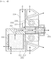
- FIG. 2 is a diagram illustrating a first cooling device 200 cooling a plated steel plate of an exemplary embodiment, viewed from the front.
- the first cooling device 200 cooling a plated steel plate may include a cooling water spraying unit 220 spraying cooling water onto the plated steel plate S, and an electrifying unit 230 disposed on at least one side of the cooling water spraying unit 220 and electrifying the cooling water, and the cooling water spraying unit 220 may be installed to spray the cooling water while the cooling is electrified by the electrifying unit 230.
- the first cooling device 200 cooling the plated steel plate may spray the cooling water in an electrified state.
- the cooling water spraying unit 220 is provided on one side of the electrifying unit 230, the cooling water may be sprayed in electrified state, and the sprayed cooling water may be electrified to have the same polarity such that an electrification efficiency of the cooling water may improve, and an attachment efficiency of the cooling water attached to the plating layer on the steel plate S and also a cooling efficiency may accordingly improve.
- the cooling water spraying unit 220 of the first cooling device 200 cooling a plated steel plate may include a first vessel 222 receiving cooling water; a water channel 221 connected to the first vessel 222 and having the cooling water to move therein; and a nozzle 223 connected to the water channel 221, receiving cooling water from the first vessel 222, and spraying the cooling water onto the plated steel plate.
- the water channel 221 may transfer the sprayed cooling water from the first vessel 222 to the nozzle 223, and a portion of the water channel 221 may penetrate through the electrifying unit 230 and may be provided in a front region of the electrifying unit 230 in a spraying direction to electrify the cooling water to provide the same polarity to the cooling water and to spray the cooling water.
- the configuration above will be described in greater detail later.
- the first vessel 222 may be provided with the cooling water to be sprayed, and may be connected to a providing pipe to receive the cooling water W from the outside, and also allow some of the stored cooling water to be discharged through a drain pipe. However, most of the stored cooling water may be delivered to the nozzle 223 through the water channel 221 and may be sprayed to the steel plate S.
- the first vessel 222 may be grounded to a ground, and may be formed of a conductive material such that, when the cooling water is electrified, the first vessel 222 may receive a negative electric charge from the ground, or may discharge a negative electric charge, and the like.
- the first vessel 222 of the first cooling device 200 cooling a plated steel plate in the exemplary embodiment may be grounded to a ground.
- the cooling water in the first vessel 222 is electrified to have the same polarity by an electrode 232, the issue of offset in electrified polarity while the cooling water is sprayed, and the like, may be prevented.
- the nozzle 223 may spray the cooling water transferred through the water channel 221 from the first vessel 222 to the steel plate S.
- the nozzle 223 may include a hole having a shape in which a size of a spraying channel through which the cooling water is sprayed gradually decreases such that a spraying speed of the cooling water may increase.
- the nozzle 223 of the first cooling device 200 cooling a plated steel plate in the exemplary embodiment may also spray the cooling water in droplet form.
- the nozzle 223 may be provided as a spray nozzle which may spray the cooling water in droplet form such that a spraying area of the sprayed cooling water may be expanded.
- a plurality of the nozzles 223 may be provided to correspond to a width of the steel plate S. The configuration above will be described in greater detail with reference to FIG. 3 later.
- the first cooling device 200 cooling a plated steel plate in the exemplary embodiment may further include a first body unit 210 provided on a moving path of the steel plate.
- the cooling water spraying unit 220 may be coupled to the first body unit 210, and may spray the cooling water to the steel plate S.
- the electrifying unit 230 may be coupled to the first body unit 210, and may be provided such that the water channel 221 through which the cooling water of the cooling water spraying unit 220 moves may penetrate through the electrifying unit 230, and may electrify the cooling water sprayed from the cooling water spraying unit 220 such that the cooling water may have the same polarity.
- the electrifying unit 230 of the first cooling device 200 cooling a plated steel plate in the exemplary embodiment may be coupled to the first body unit 210 while being integrated with the cooling water spraying unit 220.
- the first cooling device 200 cooling a plated steel plate is configured such that the electrifying unit 230 is integrated with the cooling water spraying unit 220 spraying the cooling water, and the cooling water may be sprayed after the cooling water has the polarity.
- the first body unit 210 may serve as a body to which the cooling water spraying unit 220 and the electrifying unit 230 are coupled, and may be provided on a moving path of the steel plate S coated with a plating layer on which some of a plating solution L is solidified.
- the first body unit 210 may further include a first frame 211 to control a spraying area of the cooling water sprayed from the cooling water spraying unit 220, and may also include a first gas curtain 212.
- the configuration above will be described in greater detail with reference to FIG. 4 later.
- the cooling water spraying unit 220 may be configured to spray the cooling water to the steel plate S.
- the cooling water spraying unit 220 may spray the cooling water after electrifying the cooling water because of an arrangement relationship with the electrifying unit 230.
- the cooling water spraying unit 220 of the first cooling device 200 cooling a plated steel plate may be configured such that some of the cooling water spraying unit 220 may be grounded to a ground to discharge a negative electric charge to the ground when an electrostatic charge is applied to the electrifying unit 230, or to receive a negative electric charge from the ground.
- a negative electric charge may be discharged from the cooling water through a portion of the cooling water spraying unit 220 grounded to a ground, or a negative electric charge may be transferred to the cooling water such that the cooling water may be electrified to have a polarity.
- the electrification to form a polarity may be performed as the electrifying unit 230 is provided on one side of the cooling water spraying unit 220.
- the electrifying unit 230 of the first cooling device 200 cooling a plated steel plate may include an electrode 232 forming an electric field by receiving an electrostatic charge, and as the water channel 221 through which the cooling water moves is provided to intersect the electrode 232, the cooling water spraying unit 220 may electrify the cooling water such that the cooling water may have a polarity before the cooling water is sprayed.
- the electrode 232 of the first cooling device 200 cooling a plated steel plate in the exemplary embodiment may be disposed in upper and lower portions of the water channel 221.
- the first cooling device 200 cooling a plated steel plate may include a spraying pressure providing portion 224, and the spraying pressure providing portion 224 may be provided to increase spraying force of the cooling water transferred to the nozzle 223 from the first vessel 222 through the water channel 221.
- the cooling water may be sprayed by the nozzle 223 using only spraying force produced by the moving cooling water, but to increase the spraying force of the cooling water, the spraying pressure providing portion 224 may be provided. Also, the cooling water may also be sprayed by spraying pressure applied by the spraying pressure providing portion 224.
- the cooling water spraying unit 220 of the first cooling device 200 cooling a plated steel plate in the exemplary embodiment may include the spraying pressure providing portion 224 connected to the nozzle 223 and providing gas to apply spraying pressure to the cooling water.
- the gas A may be air, and the spraying pressure providing portion 224 may be configured to receive the gas A from the outside through a pipe, and to provide the received gas A to the nozzle 223, a flow channel of the gas A connected up to the nozzle 223 may be provided.
- the electrifying unit 230 may be configured to spray the cooling water while the cooling water is electrified to have a polarity.
- the electrifying unit 230 may be integrated with the cooling water spraying unit 220, and may be coupled to the first body unit 210.
- the water channel 221 of the cooling water spraying unit 220 may penetrate through the electrifying unit 230, and the electrifying unit 230 may be disposed in a rear region of the water channel 221 in a spraying direction of the cooling water, rather than being disposed in a portion of the water channel 221, such that the electrifying unit 230 may apply the same polarity to the cooling water and may spray the cooling water.
- the configuration above will be described in greater detail later.
- the electrifying unit 230 of the first cooling device 200 cooling a plated steel plate may further include an electrode support portion 231 supporting the electrode 232, and the electrode support portion 231 may be installed to be integrated with or coupled to the first body unit 210 in a front region of the first body unit 210 in which the first vessel 222 is disposed.
- At least portion of the water channel 221 of the cooling water spraying unit 220 through which the cooling water flows may be provided in a front region of the electrode 232 with reference to a spraying direction of the cooling water, and the cooling water in the water channel 221 may be electrified to have the same polarity.
- the water channel 221 may be configured to transfer the sprayed cooling water to the nozzle 223 from the first vessel 222, and the water channel 221 may penetrate through the electrode 232 such that a portion of the water channel 221 may be provided in a front region of the electrode 232, thereby electrifying the cooling water moving in the water channel 221 to apply the same polarity to the cooling water.
- the cooling water is electrified such that the polarity provided to the cooling water may be adjusted depending on the electrified polarity applied by the electrode 232, the overall cooling water may be electrified to have the same polarity and may be sprayed.
- the electrode support portion 231 may be configured to support the electrode 232 such that the electrode 232 may be integrated with the cooling water spraying unit 220.
- the electrode support portion 231 may be coupled to the first body unit 210 to which the cooling water spraying unit 220 is coupled, and may include the electrode 232 inside the electrode support portion 23.
- the electrode 232 may be connected to a high voltage generator PS applying an external electrostatic charge and may receive an electrostatic charge.
- the high voltage generator PS may apply a high voltage while being grounded to a ground and being connected to the electrode 232 such that the electrode 232 may maintain a state in which a positive electrostatic charge or a negative electrostatic charge is applied.
- the high voltage generator PS may discharge a negative electric charge in the electrode 232 through a ground.
- the cooling water in the water channel 221 adjacent to the electrode 232 may be electrified to have a unipolarity, and accordingly, the electrified cooling water may have improved adhesive force to be adhered to the steel plate, and the cooling water may have improved cooling ability.
- the electrification of the cooling water may be performed as the first vessel 222 connected to the water channel 221 is grounded to a ground and receives a negative electric charge from or discharges a negative electric charge to the ground to electrify the cooling water to apply a unipolarity to the cooling water.
- FIG. 3 is a perspective diagram illustrating a first cooling device 200 cooling a plated steel plate according to an exemplary embodiment.
- a nozzle 223 of a first cooling device 200 cooling a plated steel plate in the exemplary embodiment may be provided as a plurality of nozzles 223 in a width direction of the steel plate S.
- the nozzles may be disposed as above to uniformly perform the cooling of the steel plate S.
- the plurality of nozzles 223 may be provided in a width direction of the steel plate S.
- FIG. 4 is a diagram illustrating an exemplary embodiment in which a first cooling device 200 cooling a plated steel plate includes a first gas curtain according to an exemplary embodiment, viewed from the front.
- the first cooling device 200 cooling a plated steel plate in the exemplary embodiment may include a first gas curtain 212 provided in a peripheral region of the nozzle 223, and inducing the sprayed cooling water to the steel plate S.
- a spraying area of the cooling water sprayed from the cooling water spraying unit 220 may be controlled.
- gas A may be sprayed from the first gas curtain 212 such that the gas A may form a shield around the sprayed cooling water, thereby limiting a spraying area of the cooling water.
- the first gas curtain 212 may also be included in the first body unit 210, but an exemplary embodiment thereof is not limited thereto.
- the first gas curtain 212 may be implemented in various manners as long as the first gas curtain 212 is connected to the nozzle 223 and induces the sprayed cooling water to the steel plate.
- the first gas curtain 212 may be connected to a pipe receiving the gas A from the outside.
- FIG. 1 is a diagram illustrating a plating facility according to an exemplary embodiment, viewed from the front.
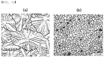
- FIG. 10A is a picture showing a coarsened state of spangle patterns created when a plating layer is cooled in the related art
- FIG. 10B is a picture showing a state of micronized spangle patterns created when a plating layer is cooled in the present disclosure.
- a plating facility in another exemplary embodiment may include a plating bath 300, and a first cooling device 200 cooling a plated steel plate provided on a moving path of a plated steel plate S discharged from the plating bath 300.
- the plating bath 300 may be configured to coat the steel plate S with a plating solution L.
- the plating bath 300 may include a plating solution L such as a melted zinc solution, and the like, and may include a pot roll 400 guiding movement of the steel plate S .
- the first cooling device 200 cooling a plated steel plate in the plating facility described in the aforementioned exemplary embodiment may perform the cooling of a plating layer of the steel plate S cooled and partially solidified in a second cooling device 100 cooling a plated steel plate, and may complete the cooling of the plating layer.
- the first cooling device 200 may receive the steel plate S on which the plating solution L coating an exterior surface of the steel plate S is cooled to a temperature lower than a melting temperature of the plating solution L and may spray the cooling water having a polarity by electrification to the steel plate S to cool the steel plate.
- the first cooling device 200 cooling a plated steel plate may be disposed in a rear region of a moving path of the steel plate S, further behind than the second cooling device 100 cooling a plated steel plate.
- the steel plate S may primarily pass through the second cooling device 100 cooling a plated steel plate after being discharged from the plating bath 300, and may secondarily pass through the first cooling device 200 cooling a plated steel plate.
- a moving path in which the steel plate S is coated with the plating solution L and is cooled may be configured to have a layout in which at least one moving path is changed, rather than forming the moving path in a straight line, such that the plating facility including the moving path of the steel plate S may have a reduced size.
- the moving path of the steel plate S may be configured to have a " ⁇ " shape, opening towards a surface of the ground.
- the first cooling device 200 of the plating facility in the exemplary embodiment may be provided in a first region in which the moving path of the steel plate is formed in an upper direction of the plating bath, a second region connected to the first region such that the moving path of the steel plate is formed horizontally to a surface of the ground, and a third region connected to the second region such that the moving path of the steel plate is formed in a lower direction.
- a water cooling device 600 may be provided in an outlet portion of the first cooling device 200.
- the plating facility in the exemplary embodiment may include the water cooling device 600 provided in a rear region of the moving path of the steel plate S, further behind than the first cooling device 200, and when the plating solution L coating an exterior surface of the steel plate S is completely solidified by the first cooling device 200, the water cooling device 600 may receive the steel plate S from the first cooling device 200 and may cool the steel plate S using water.
- the water cooling device 600 may include a water cooling portion 610 cooling the steel plate S by supplying cooling water to the steel plate S, and a drying portion 620 drying the steel plate S discharged from the water cooling portion 610.
- the plating facility may further include the second cooling device 100 cooling a plated steel plate disposed in an outlet portion from which the steel plate S is discharged, turning the cooling water into mist by ultrasonic vibrations, and spraying the mist to the steel plate S along with the gas A.
- a speed of cooling the steel plate S coated with the plating solution L may improve, and thus, spangle patterns formed on the plating solution L such as a zinc solution, and the like, may be refined.
- a cooling speed in which spangle patterns may be obtained may be refined as in FIG. 10B .
- the time for cooling and solidifying the plating solution L coating the steel plate S may be reduced, and a cooling line may be shortened, thereby reducing a size of the plating facility.
- the second cooling device 100 cooling a plated steel plate may be configured to perform cooling at an earlier stage of when the steel plate S coated with the plating solution L is discharged from the plating bath 300, and may perform the cooling of the non-solidified plating solution L.
- the second cooling device 100 of the plating facility in the exemplary embodiment may cool the plating solution L on a surface of the steel plate S discharged from the plating bath 300 in a temperature higher than a melting temperature of the plating solution L, and may cool the plating solution L such that the plating solution L may have a temperature lower than the melting temperature of the plating solution L at least, and the second cooling device 100 may transfer the steel plate to the first cooling device 200.
- the second cooling device 100 transfers the steel plate S to the first cooling device 200 after the overall plating solution L is solidified, pit marks, recesses formed in the plating layer caused by the cooling water used when the steel plate S is cooled in the first cooling device 200, may be prevented.
- the second cooling device 100 may also spray micronized moisture particles formed by ultrasonic waves such that pit marks, recesses formed in a non-solidified plating layer, may be prevented, and cooling ability may improve.
- the configuration above will be described in greater detail with reference to FIGS. 5 to 8 later.
- the second cooling device 100 cooling a plated steel plate includes a filter unit 140
- sizes of mist particles sprayed to the plating layer may be adjusted using a difference in moving inertial force of the mist particles depending on sizes of the mist particles formed by a ultrasonic unit 130, thereby improving an efficiency of preventing the pit marks.
- an air knife 500 may be provided between the plating bath 300 and the second cooling device 100 cooling a plated steel plate, and the air knife 500 may adjust a thickness of the plating solution L coated in the plating bath 300.
- the plating facility in the exemplary embodiment may include the air knife 500 provided between the plating bath 300 and the second cooling device 100 to adjust a thickness of the plating solution L coating the steel plate S.
- FIG. 5 is a diagram illustrating a second cooling device 100 cooling a plated steel plate according to an exemplary embodiment, viewed from the front.
- the second cooling device 100 cooling a plated steel plate may include a second body unit 110 provided on a moving path of a steel plate S of which an exterior surface is coated with a non-solidified plating solution L, a gas spraying unit 120 provided in the second body unit 110 and spraying gas A to the steel plate S, and an ultrasonic unit 130 provided in the second body unit 110 and turning cooling water into mist and spraying the mist to the steel plate S along with gas A sprayed from the gas spraying unit 120.
- the second cooling device 100 cooling a plated steel plate may be configured such that the mist of the cooling water formed by the ultrasonic unit 130 may be sprayed, and when the plating solution L is cooled by the gas A, pit marks, recesses formed in a non-solidified plating solution L, may be prevented, and cooling ability may improve.
- the second body unit 110 may serve as a body in which the gas spraying unit 120 and the ultrasonic unit 130 are provided.
- the second body unit 110 may also be configured to spray the gas A provided from the gas spraying unit 120 and the mist of the cooling water provided from the ultrasonic unit 130 together to the steel plate S coated with the plating solution L.
- the second body unit 110 may include a second frame 111, a slit nozzle 112, and a second gas curtain 113, and the configuration above will be described in greater detail with reference to FIGS. 7 and 8 later.
- the second body unit 110 may be provided on a moving path of the steel plate S coated with the non-solidified plating solution L, discharged from the plating bath 300, such that the second cooling device 100 cooling a plated steel plate may primarily cool down the steel plate S discharged from the plating bath 300.
- the gas spraying unit 120 may spray the gas A to cool the non-solidified plating solution L coating the steel plate S.
- the gas spraying unit 120 may include a gas providing portion 121, and may also include a temperature adjusting portion 122 adjusting a temperature of the gas A to a relatively low temperature or a relatively high temperature to improve a cooling efficiency obtained by spraying the gas A.
- the configuration above will be described in greater detail with reference to FIG. 6 later.
- the ultrasonic unit 130 may provide the mist of the cooling water to the gas A to improve cooling ability of the gas A sprayed from the gas spraying unit 120.
- the gas A may be air, and the ultrasonic unit 130 may turn the cooling water into mist using ultrasonic vibrations and may provide the mist to the slit nozzle 112 of the second body unit 110 along with the gas A provided from the gas spraying unit 120, and the mist and the gas may be sprayed to the plating solution L coating the steel plate S.
- the ultrasonic unit 130 may include a second vessel 131, an ultrasonic generator 132, a mist guiding portion 133.
- the ultrasonic unit 130 of the second cooling device 100 cooling a plated steel plate in the exemplary embodiment may include the second vessel 131 provided in the second body unit 110 and provided with the cooling water, the ultrasonic generator 132 provided in the second vessel 131 and turning the cooling water into mist by generating ultrasonic waves by vibrations, and the mist guiding portion 133 provided in an upper portion of the second vessel 131 and inducing the mist to a position in which the steel plate S is provided.
- the second vessel 131 may be configured to be provided with the cooling water to be turned into mist when the ultrasonic generator 132 generates vibrations, and may be provided in the second body unit 110.
- a pipe through which the cooling water W is supplied may be connected to the second vessel 131.
- the ultrasonic generator 132 may generate ultrasonic vibrations to turn the cooling water into mist, and may be provided in the second vessel 131 to which the cooling water is provided.
- the ultrasonic generator 132 may be electrically connected to a voltage source to generate ultrasonic vibrations, and may be formed of a material such as a metal, a crystal, ceramics, and the like, which can turn electric energy supplied from the voltage source into vibration energy.
- the mist guiding portion 133 may be configured to, when the cooling water provided to the second vessel 131 is turned into mist by ultrasonic vibrations provided from the ultrasonic generator 132, guide the mist to move to the slit nozzle 112.
- the mist guiding portion 133 provided in an upper portion of the second vessel 131 may have a cap shape, and a hole may be formed in a direction towards the slit nozzle 112.
- a flange extending towards the slit nozzle 112 may be formed around the hole.
- a filter unit 140 for adjusting sizes of mist particles may be provided between the mist guiding portion 133 and the slit nozzle 112, and the filter unit 140 may control sizes of the mist particles provided to the slit nozzle 112.
- FIG. 6 is a diagram illustrating an exemplary embodiment in which a temperature adjusting portion 122 of a gas spraying unit 120 is provided externally of a gas providing portion 121 in a second cooling device 100 cooling a plated steel plate, viewed from a front.
- the gas spraying unit 120 of the second cooling device 100 cooling a plated steel plate in the exemplary embodiment may include a gas providing portion 121 provided in the second body unit 110, receiving gas A from the outside, and spraying the gas to a steel plate S, and a temperature adjusting portion 122 provided in the gas providing portion 121 and adjusting a temperature of the gas A.
- the temperature adjusting portion 122 adjusting a temperature of the gas A to a relatively low temperature or a relatively high temperature may be included.
- the gas providing portion 121 may provide the gas A to the slit nozzle 112, and may receive the high pressure gas A from the outside.
- a pipe may be connected to the gas providing portion 121 for the gas providing portion 121 to receive the gas A.
- the gas A may be air.
- the temperature adjusting portion 122 may adjust a temperature of the gas A provided from the gas providing portion 121, and may be provided as a cooling pipe to lower the temperature of the gas A, for example.
- the temperature adjusting portion 122 may be provided inside the gas providing portion 121 such that the temperature adjusting portion 122 may be directly in contact with the gas A provided from the gas providing portion 121, and may improve an efficiency of controlling the temperature of the gas A.
- An exemplary embodiment thereof is illustrated in FIG. 5 .
- the temperature adjusting portion 122 may also be provided externally of the gas providing portion 121. In this case, a flow channel of the gas A flowing in the gas providing portion 121 may not be interfered, and thus, a flow velocity of the gas A may be maintained. An exemplary embodiment thereof is illustrated in FIG. 6 .
- a region of the gas providing portion 121 in which the temperature adjusting portion 122 is disposed may have a size in which heat exchange between the gas A and the temperature adjusting portion 122 may be sufficiently performed.
- the gas spraying unit 120 may further include a gas amount adjusting portion 123, and the amount of gas transferred to the gas providing portion 121 from the outside may be adjusted.
- the gas spraying unit 120 of the second cooling device 100 cooling a plated steel plate in the exemplary embodiment may include the gas amount adjusting portion 123 provided in the gas providing portion 121, and adjusting the amount of gas transferred from the outside.
- the gas amount adjusting portion 123 may be provided to adjust the amount of gas sprayed to the steel plate S from the slit nozzle 112 of the second body unit 110, and also to adjust predetermined cooling ability in consideration of the amount of mist formed in the ultrasonic unit 130 to cool down the plating solution on the steel plate S to a target temperature.
- FIG. 7 is a perspective diagram illustrating a second cooling device 100 cooling a plated steel plate according to an exemplary embodiment.
- a second body unit 110 of the second cooling device 100 cooling a plated steel plate in the exemplary embodiment may include a second frame 111 provided on a moving path of a steel plate S, and a slit nozzle 112 provided in a front end of the second frame 111 opposing the steel plate S and having a width greater than a width of the steel plate S at least to spray gas A provided from a gas spraying unit 120 and mist provided from a ultrasonic unit 130 to the steel plate S.
- the second body unit 110 may include the second frame 111 and the slit nozzle 112 to spray the gas A provided from the gas spraying unit 120 and the mist of cooling water provided from the ultrasonic unit 130 together to the steel plate S coated with the plating solution L.
- the second frame 111 may be an element in which the gas spraying unit 120 and the ultrasonic unit 130 are provided, and the slit nozzle 112 may spray the gas A and the mist to a non-solidified plating solution L.
- the slit nozzle 112 may have an elongated hole shape with a width greater than a width of the steel plate S, and may spray the gas A and the mist uniformly in a width direction of the steel plate S and may uniformly perform the cooling of the non-solidified plating solution L.
- FIG. 8 is a diagram illustrating an exemplary embodiment in which a second body unit 110 includes a second gas curtain 113 in a second cooling device 100 cooling a plated steel plate according to an exemplary embodiment, viewed from a front.
- the second body unit 110 of the second cooling device 100 cooling a plated steel plate in the exemplary embodiment may include the second gas curtain 113 provided in a peripheral portion of a slit nozzle 112, and inducing sprayed gas A and mist to a steel plate S.
- the second body unit 110 may include the second gas curtain 113 to, when the gas A provided from a gas spraying unit 120 and the mist of cooling water provided from a ultrasonic unit 130 are sprayed to a plating solution L coating the steel plate S, control a position to which the gas and the mist are sprayed.
- the second gas curtain 113 may be provided in a peripheral portion of the slit nozzle 112, and may be provided to surround the peripheral portion of the slit nozzle 112 desirably.
- a pipe through which the gas A is provided from the outside may be disposed, and the gas A may be air.
- the gas A may be air.
- FIG. 9 is a diagram illustrating an operational state of a filter unit 140 in a second cooling device 100 cooling a plated steel plate according to an exemplary embodiment, viewed from the front.
- the second cooling device 100 cooling a plated steel plate may include a filter unit 140 provided in a second body unit 110, and adjusting sizes of mist particles sprayed to a steel plate S.
- the filter unit 140 may adjust sizes of mist particles sprayed to a plating layer using a difference in moving inertial force of the mist particles depending on sizes of the mist particles formed by the ultrasonic unit 130.
- the filter unit 140 may include a filter frame 141 and a control plate 142.
- the filter unit 140 of the second cooling device 100 cooling a plated steel plate may include the filter frame 141 provided on a moving path of the mist formed in the ultrasonic unit 130 and coupled to the second body unit 110, and the control plate 142 provided in the filter frame 141, and changing a moving path of some of mist particles and allowing the other mist particles to collide with the control plate by moving inertial force.
- the filter frame 141 may be a basic frame of a filter unit 140, and may be provided in the second body unit 110, more specifically, provided between a mist guiding portion 133 from which the mist formed in the ultrasonic unit 130 is discharged and a slit nozzle 112.
- the control plate 142 may be provided in the filter frame 141, and may change a moving path of some of mist particles penetrating and flowing through the filter frame 141.
- particles (be) having a relatively great moving inertial force among the moving mist particles may not change a moving path thereof, or only a moving path of some of the mist particles may be changed, and the mist particles may collide with the control plate 142.
- the collided particles may not move to the slit nozzle 112, and may be accumulated on the control plate 142. Accordingly, sizes of the particles may increase such that the particles may be dropped into a second vessel 131.
- a moving path of the particles (se) having relatively low moving inertial force among the moving mist particles may be sufficiently changed to not be collided with the control plate 142, and thus, the particles may move to the slit nozzle 112 without being collided with the control plate 142.
- the moving inertial force is a value proportional to a mass of a particle
- sizes of the mist particles provided to the slit nozzle 112 may be adjusted.
- control plate 142 may be provided as a plurality of control plates 142 in the filter frame 141 with certain gaps.
- control plate 142 may be configured to be provided as a plurality of control plates 142 in the filter frame 141 with certain gaps.
- the provided mist particles guided by the mist guiding portion 133 may be efficiently filtered.
- control plate 142 of the second cooling device 100 cooling a plated steel plate may be inclined toward the moving path of the mist particles.
- the control plate may be configured to be inclined toward the moving path of the mist particles to adjust a degree of change in the moving path of the mist particles.
- a rate of change in moving path of the mist particles may increase such that only particles having relatively small sizes may pass through and may be provided to the slit nozzle 112.
- a rate of change in moving path of the mist particles may decrease such that relatively large-sized particles may also pass through and may be provided to the slit nozzle 112.
- control plate may be replaced with a filter unit 140 having a different degree of inclination, or an angle adjusting motor, and the like, may be connected to adjust the angle of the control plate.
- a method of cooling a plated steel plate may include a process of coating a steel plate S with a plating solution L, a wiping process of adjusting a thickness of the plating solution L coating the steel plate S, and a cooling process, and the cooling process includes cooling the steel plate S by spraying cooling water onto the steel plate S, and the cooling water may be sprayed while being electrified.
- the cooling process of the method of cooling a plated steel plate in the exemplary embodiment may include a pre-cooling stage of cooling the steel plate S coated with the plating solution L, and a post-cooling stage of cooling the steel plate cooled in the pre-cooling stage by spraying the cooling water having the same polarity by electrification.
- the plating process may be performed such that a plating bath 300 may be moved while being supported by a pot roll 400, and the like.
- an exterior surface of the steel plate S may be coated with the plating solution L while the steel plate S passes through the plating bath 300 in which the plating solution L is contained.
- a thickness of the plating solution L coating the steel plate S may be adjusted by spraying gas such as air, and the like, such that a thickness of a plating layer to be formed may be adjusted.
- the cooling of the steel plate S discharged from the plating bath 300 and passing through the wiping process may be performed.
- the plating solution L which is still in a melted state, may be cooled using a second cooling device 100, and to prevent pit marks, recesses formed when the plating solution is solidified, and the like, gas may be sprayed.
- mist a micronized form of cooling water formed by ultrasonic vibrations, may also be sprayed.
- the cooling may be performed by spraying the gas and the mist formed by ultrasonic waves to the plating solution L on the steel plate S, formed in a temperature higher than a melting temperature of the plating solution L, and the plating solution L may be cooled to a temperature lower than a melting temperature of the plating solution L at least, and the steel plate may be transferred to the post-cooling stage.
- cooling ability may further improve than when only gas is sprayed, and pit marks formed while the plating solution L is solidified may be prevented.
- micronized mist formed by ultrasonic vibrations, may not be sprayed, and thus, the post-cooling stage may need to be performed after the plating solution L is solidified. Otherwise, pit marks may be formed on the plating layer formed by the plating solution L.
- the plating solution L and the steel plate S are primarily cooled using the second cooling device 100 in the pre-cooling stage, in the post-cooling stage, the plating solution L and the steel plate S may be secondarily cooled using the first cooling device 200.
- the cooling is performed after receiving the plating layer cooled to a temperature lower than a melting temperature of the plating solution L from the pre-cooling stage, and thus, it may not be necessary to consider the issue of pit marks formed on the plating layer, and the cooling water may be sprayed without turning the cooling water into mist to cool the steel plate.
- the steel plate may be cooled by spraying the cooling water provided with a polarity by electrification to the steel plate.
- attachment force of the cooling water attached to the steel plate S or the plating layer may improve such that cooling ability may improve.
Landscapes
- Chemical & Material Sciences (AREA)
- Chemical Kinetics & Catalysis (AREA)
- Engineering & Computer Science (AREA)
- Materials Engineering (AREA)
- Mechanical Engineering (AREA)
- Metallurgy (AREA)
- Organic Chemistry (AREA)
- Coating With Molten Metal (AREA)
- Heat Treatments In General, Especially Conveying And Cooling (AREA)
- Application Of Or Painting With Fluid Materials (AREA)
Abstract
Description
- The present disclosure relates to a first cooling device cooling a plated steel plate, a plating facility, and a method of cooling a plated steel plate.
- In a process of manufacturing steel products, consecutive plating processes may be performed, and plated steel plates may be produced in accordance with customer requirements.
- In the consecutive plating processes, a melted plating solution, attached to a surface of a steel plate which has passed through a plating bath in which a plating solution such as zinc is provided, may be cooled to produce a plated steel plate.
- As an excessive amount of plating solution may be attached to both surfaces of the steel plate passing through the plating bath, a plating layer having an appropriate thickness may be formed using an air knife, and a non-solidified zinc solution of 460°C or higher may be solidified using a cooling device. Accordingly, a plating layer having sufficient strength may be formed on a surface of the steel plate, thereby producing a plated steel plate.
- However, when the plating solution is not cooled swiftly, it may be impossible to refine spangle patterns, crystal growth patterns created on a surface of a plating layer, and plating quality may degrade.
- Meanwhile, to solidify the plating layer, the non-solidified plating solution may be cooled using gas such as an air cooler, and the plating layer partially solidified and having a certain level of strength may be cooled by a cooling nozzle spraying cooling water.
- The reason why the steel plate coated with the plating solution is cooled using the air cooler at an earlier stage of the cooling is that, when water drops of the cooling water are sprayed onto the non-solidified plating layer, pit marks, recesses formed on a surface of the plating layer, may be created.
- In other words, the plating layer may be cooled by spraying gas at an earlier stage of the cooling such that defects on a surface of the plated steel plate may be prevented.
- Also, the plating layer partially solidified by the air cooler and having a certain level of strength may be completely solidified by spraying cooling water from the cooling nozzle onto the plating layer. To cool the plating layer using the cooling water, the cooling water may need to be attached to the plating layer and may receive heat from the plating layer, but as only some of the sprayed cooling water is attached to the plating layer, cooling ability may degrade.
- As described above, in the case of the method of cooling using gas at an earlier stage of solidification of a plating layer, a cooling speed may be relatively slow, as compared to the cooling method using cooling water, and also in the case of the cooling method by spraying cooling water, only some of the cooling water may be attached to the plating layer, which may degrade cooling ability, and spangles, a pattern of solidified zinc on the plating layer created by cooling in low speed, may excessively increase.
- In other words, when the spangle pattern disclosed in
FIG. 10A is formed on a surface of the plated steel plate, clarity and glossiness of a plated product may degrade, and it may be impossible to use the plated product to make outer plate sheets of vehicles or exterior materials of electronic products. - Also, when the insufficiently cooled plating layer is in contact with a transferring roll, some of the plating solution may be attached to the roll, and accordingly, pick-up marks, line patterns formed on a surface of the steel plate in a width direction, may be created, which may cause surface defects.
- Further, when the plating layer is cooled at low speed, sufficient time for cooling the plated steel plate may need to be secured in a facility consecutively producing plated steel plates, and a length of a cooling line may be lengthened. Accordingly, there may be a limitation in enlargement of the facility.
- An aspect of the present disclosure is to provide a first cooling device cooling a plated steel plate, a plating facility, and a method of cooling a plated steel plate, which may improve quality of a plated steel plate by increasing a speed of cooling of a plating layer coating the steel plate, and which may not require enlargement of a facility.
- According to an aspect of the present disclosure, a plated steel plate first cooling device according to an embodiment of the present invention comprises: a cooling water spraying unit for spraying cooling water to a plated steel plate, and an electrifying unit arranged on at least one side of the cooling water spraying unit so as to electrify the cooling water. The plated steel plate first cooling device according to an embodiment of the present invention may be characterized in that the cooling water spraying unit is installed such that the cooling water is sprayed while being electrified by the electrifying unit.
- The cooling water spraying unit may include a first vessel receiving cooling water, a water channel connected to the first vessel and having the cooling water to move therein, and a nozzle connected to the water channel, receiving cooling water from the first vessel, and spraying the cooling water onto the plated steel plate.
- The first vessel may be grounded to a ground.
- The electrifying unit may include an electrode forming an electric field by receiving an electrostatic charge, and the water channel may be disposed to intersect the electrode.
- The electrode may be disposed on upper and lower sides of the water channel.
- The electrifying unit may further include an electrode support portion supporting the electrode, and the electrode support portion may be installed to be integrated with or coupled to a first body unit in a front region of the first body unit in which the first vessel is disposed.
- The nozzle may spray the cooling water in droplet form.
- The nozzle may be provided as a plurality of nozzles in a width direction of the plated steel plate.
- The cooling water spraying unit may further include a spraying pressure providing portion connected to the nozzle and providing gas to apply spraying pressure to the cooling water.
- The first cooling device may further include a first gas curtain provided in a peripheral portion of the nozzle, and inducing the sprayed cooling water to the steel plate.
- According to an aspect of the present disclosure, a plating facility may include a plating bath, and a first cooling device cooling a plated steel plate provided on a moving path of a plated steel plate discharged from the plating bath.
- The plating facility may further include a second cooling device cooling a plated steel plate provided on a moving path of the steel plate between the plating bath and the first cooling device.
- The second cooling device may turn cooling water into mist using ultrasonic vibrations and may spray the mist onto the steel plate along with gas.
- The second cooling device may include a gas spraying unit spraying gas to the steel plate, a ultrasound unit turning cooling water into mist and spraying the mist to the steel plate along with the gas sprayed from the gas spraying unit, and a filter unit provided on a moving path of the mist formed in the ultrasound unit and the gas sprayed from the gas spraying unit.
- The filter unit may adjust sizes of mist particles to be sprayed to the steel plate.
- The filter unit may further include a filter frame provided on a moving path of the mist formed in the ultrasound unit, and a control plate provided in the filter frame such that a moving path of some of mist particles may be changed, and the other mist particles may collide with the control plate by moving inertial force.
- The control plate may be provided as a plurality of control plates in the filter frame with certain gaps, and the control plates may be inclined toward a moving path of the mist particles.
- According to an aspect of the present disclosure, a method of cooling a plated steel plate may include a plating process of coating the steel plate with a plating solution, a wiping process of adjusting a thickness of the plating solution coating the steel plate, and a cooling process, and the cooling process may include cooling the steel plate by spraying cooling water onto the steel plate, and the cooling water may be sprayed in electrified state.
- The cooling process may include a pre-cooling stage of cooling the steel plate coated with the plating solution, and a post-cooling stage of cooling the steel plate cooled down in the pre-cooling stage by spraying cooling water provided with the same polarity by electrification.
- A first cooling device cooling a plated steel plate, a plating facility, and a method of cooling a plated steel plate in the present disclosure may improve quality of a plated steel plate and may not require enlargement of a facility by increasing a speed of cooling of a plating layer coating the steel plate.
- Further, when the steel plate coated with a plating solution is cooled using gas at an earlier stage of the cooling, micro moisture particles formed using ultrasonic waves may also be sprayed such that pit marks, recesses formed in a non-solidified plating layer, may be prevented, and cooling ability may improve.
- Also, when cooling water is sprayed to cool the steel plate on which the plating solution coating an exterior surface of the steel plate is partially solidified, the cooling water may be sprayed while being electrified. Accordingly, an electrification efficiency of the sprayed cooling water may improve, and an attachment efficiency of the cooling water attached to some of the solidified plating layer may improve, thereby improving a cooling efficiency obtained by spraying cooling water.
-
-
FIG. 1 is a diagram illustrating a plating facility according to an exemplary embodiment, viewed from the front; -
FIG. 2 is a diagram illustrating a first cooling device cooling a plated steel plate in a plating facility according to an exemplary embodiment, viewed from the front; -
FIG. 3 is a perspective diagram illustrating a first cooling device cooling a plated steel plate in a plating facility according to an exemplary embodiment; -
FIG. 4 is a diagram illustrating an exemplary embodiment in which a first cooling device cooling a plated steel plate of a plating facility includes a first gas curtain, viewed from the front; -
FIG. 5 is a diagram illustrating a second cooling device cooling a plated steel plate in a plating facility according to an exemplary embodiment, viewed from the front; -
FIG. 6 is a diagram illustrating an exemplary embodiment in which a temperature adjusting portion of a gas spraying unit is provided externally of a gas providing portion in a second cooling device cooling a plated steel plate in a plating facility, viewed from the front; -
FIG. 7 is a perspective diagram illustrating a second cooling device cooling a plated steel plate in a plating facility according to an exemplary embodiment; -
FIG. 8 is a diagram illustrating an exemplary embodiment in which a second body unit includes a second gas curtain in a second cooling device cooling a plated steel plate in a plating facility according to an exemplary embodiment, viewed from the front; -
FIG. 9 is a diagram illustrating an operational state of a filter unit in a second cooling device cooling a plated steel plate in a plating facility according to an exemplary embodiment, viewed from the front; and -
FIG. 10 is pictures illustrating a state of coarsened spangle patterns created when a plating layer is cooled in the related art, and a state of micronized spangle patterns created when a plating layer is cooled in the present disclosure. - Hereinafter, embodiments of the present disclosure will be described with reference to the accompanied drawings. The present disclosure, however, is not limited to exemplary embodiments, and it is to be understood that various other embodiments included in other prior inventions or in the scope of the present disclosure may easily be made by addition, modification, elimination, and the like, of other elements within the same scope of invention, and the embodiments may also be included in the scope of the present disclosure.
- Also, in the drawings, the elements having the same functions within the scope of the present disclosure will be indicated by the same reference numerals.
- In the present disclosure, a speed of cooling of a plating layer coating a steel plate S may be increased such that quality of the plated steel plate S may improve, and enlargement of a facility may not be necessary.
- Referring to the diagrams,
FIG. 2 is a diagram illustrating afirst cooling device 200 cooling a plated steel plate of an exemplary embodiment, viewed from the front. According toFIG. 2 , thefirst cooling device 200 cooling a plated steel plate may include a coolingwater spraying unit 220 spraying cooling water onto the plated steel plate S, and anelectrifying unit 230 disposed on at least one side of the coolingwater spraying unit 220 and electrifying the cooling water, and the coolingwater spraying unit 220 may be installed to spray the cooling water while the cooling is electrified by theelectrifying unit 230. - As described above, the
first cooling device 200 cooling the plated steel plate may spray the cooling water in an electrified state. - As the cooling
water spraying unit 220 is provided on one side of theelectrifying unit 230, the cooling water may be sprayed in electrified state, and the sprayed cooling water may be electrified to have the same polarity such that an electrification efficiency of the cooling water may improve, and an attachment efficiency of the cooling water attached to the plating layer on the steel plate S and also a cooling efficiency may accordingly improve. - The cooling
water spraying unit 220 of thefirst cooling device 200 cooling a plated steel plate may include afirst vessel 222 receiving cooling water; awater channel 221 connected to thefirst vessel 222 and having the cooling water to move therein; and anozzle 223 connected to thewater channel 221, receiving cooling water from thefirst vessel 222, and spraying the cooling water onto the plated steel plate. - The
water channel 221 may transfer the sprayed cooling water from thefirst vessel 222 to thenozzle 223, and a portion of thewater channel 221 may penetrate through theelectrifying unit 230 and may be provided in a front region of theelectrifying unit 230 in a spraying direction to electrify the cooling water to provide the same polarity to the cooling water and to spray the cooling water. The configuration above will be described in greater detail later. - The
first vessel 222 may be provided with the cooling water to be sprayed, and may be connected to a providing pipe to receive the cooling water W from the outside, and also allow some of the stored cooling water to be discharged through a drain pipe. However, most of the stored cooling water may be delivered to thenozzle 223 through thewater channel 221 and may be sprayed to the steel plate S. - The
first vessel 222 may be grounded to a ground, and may be formed of a conductive material such that, when the cooling water is electrified, thefirst vessel 222 may receive a negative electric charge from the ground, or may discharge a negative electric charge, and the like. - In other words, the
first vessel 222 of thefirst cooling device 200 cooling a plated steel plate in the exemplary embodiment may be grounded to a ground. - As the cooling water in the
first vessel 222 is electrified to have the same polarity by anelectrode 232, the issue of offset in electrified polarity while the cooling water is sprayed, and the like, may be prevented. - The
nozzle 223 may spray the cooling water transferred through thewater channel 221 from thefirst vessel 222 to the steel plate S. - The
nozzle 223 may include a hole having a shape in which a size of a spraying channel through which the cooling water is sprayed gradually decreases such that a spraying speed of the cooling water may increase. - The
nozzle 223 of thefirst cooling device 200 cooling a plated steel plate in the exemplary embodiment may also spray the cooling water in droplet form. - For example, the
nozzle 223 may be provided as a spray nozzle which may spray the cooling water in droplet form such that a spraying area of the sprayed cooling water may be expanded. - Further, a plurality of the
nozzles 223 may be provided to correspond to a width of the steel plate S. The configuration above will be described in greater detail with reference toFIG. 3 later. - The
first cooling device 200 cooling a plated steel plate in the exemplary embodiment may further include afirst body unit 210 provided on a moving path of the steel plate. The coolingwater spraying unit 220 may be coupled to thefirst body unit 210, and may spray the cooling water to the steel plate S. Theelectrifying unit 230 may be coupled to thefirst body unit 210, and may be provided such that thewater channel 221 through which the cooling water of the coolingwater spraying unit 220 moves may penetrate through theelectrifying unit 230, and may electrify the cooling water sprayed from the coolingwater spraying unit 220 such that the cooling water may have the same polarity. - The
electrifying unit 230 of thefirst cooling device 200 cooling a plated steel plate in the exemplary embodiment may be coupled to thefirst body unit 210 while being integrated with the coolingwater spraying unit 220. - As described above, as the
first cooling device 200 cooling a plated steel plate is configured such that theelectrifying unit 230 is integrated with the coolingwater spraying unit 220 spraying the cooling water, and the cooling water may be sprayed after the cooling water has the polarity. - The
first body unit 210 may serve as a body to which the coolingwater spraying unit 220 and theelectrifying unit 230 are coupled, and may be provided on a moving path of the steel plate S coated with a plating layer on which some of a plating solution L is solidified. - The
first body unit 210 may further include afirst frame 211 to control a spraying area of the cooling water sprayed from the coolingwater spraying unit 220, and may also include afirst gas curtain 212. The configuration above will be described in greater detail with reference toFIG. 4 later. - The cooling
water spraying unit 220 may be configured to spray the cooling water to the steel plate S. The coolingwater spraying unit 220 may spray the cooling water after electrifying the cooling water because of an arrangement relationship with theelectrifying unit 230. - For example, the cooling
water spraying unit 220 of thefirst cooling device 200 cooling a plated steel plate may be configured such that some of the coolingwater spraying unit 220 may be grounded to a ground to discharge a negative electric charge to the ground when an electrostatic charge is applied to theelectrifying unit 230, or to receive a negative electric charge from the ground. - In other words, by the electrostatic charge applied by the
electrifying unit 230, a negative electric charge may be discharged from the cooling water through a portion of the coolingwater spraying unit 220 grounded to a ground, or a negative electric charge may be transferred to the cooling water such that the cooling water may be electrified to have a polarity. - Also, the electrification to form a polarity may be performed as the
electrifying unit 230 is provided on one side of the coolingwater spraying unit 220. - For example, the
electrifying unit 230 of thefirst cooling device 200 cooling a plated steel plate may include anelectrode 232 forming an electric field by receiving an electrostatic charge, and as thewater channel 221 through which the cooling water moves is provided to intersect theelectrode 232, the coolingwater spraying unit 220 may electrify the cooling water such that the cooling water may have a polarity before the cooling water is sprayed. - For example, the
electrode 232 of thefirst cooling device 200 cooling a plated steel plate in the exemplary embodiment may be disposed in upper and lower portions of thewater channel 221. - The
first cooling device 200 cooling a plated steel plate may include a sprayingpressure providing portion 224, and the sprayingpressure providing portion 224 may be provided to increase spraying force of the cooling water transferred to thenozzle 223 from thefirst vessel 222 through thewater channel 221. - In other words, the cooling water may be sprayed by the
nozzle 223 using only spraying force produced by the moving cooling water, but to increase the spraying force of the cooling water, the sprayingpressure providing portion 224 may be provided. Also, the cooling water may also be sprayed by spraying pressure applied by the sprayingpressure providing portion 224. - As described above, the cooling
water spraying unit 220 of thefirst cooling device 200 cooling a plated steel plate in the exemplary embodiment may include the sprayingpressure providing portion 224 connected to thenozzle 223 and providing gas to apply spraying pressure to the cooling water. - The gas A may be air, and the spraying
pressure providing portion 224 may be configured to receive the gas A from the outside through a pipe, and to provide the received gas A to thenozzle 223, a flow channel of the gas A connected up to thenozzle 223 may be provided. - The
electrifying unit 230 may be configured to spray the cooling water while the cooling water is electrified to have a polarity. - To this end, the
electrifying unit 230 may be integrated with the coolingwater spraying unit 220, and may be coupled to thefirst body unit 210. - The
water channel 221 of the coolingwater spraying unit 220 may penetrate through theelectrifying unit 230, and theelectrifying unit 230 may be disposed in a rear region of thewater channel 221 in a spraying direction of the cooling water, rather than being disposed in a portion of thewater channel 221, such that theelectrifying unit 230 may apply the same polarity to the cooling water and may spray the cooling water. The configuration above will be described in greater detail later. - The
electrifying unit 230 of thefirst cooling device 200 cooling a plated steel plate may further include anelectrode support portion 231 supporting theelectrode 232, and theelectrode support portion 231 may be installed to be integrated with or coupled to thefirst body unit 210 in a front region of thefirst body unit 210 in which thefirst vessel 222 is disposed. - At least portion of the
water channel 221 of the coolingwater spraying unit 220 through which the cooling water flows may be provided in a front region of theelectrode 232 with reference to a spraying direction of the cooling water, and the cooling water in thewater channel 221 may be electrified to have the same polarity. - In other words, the
water channel 221 may be configured to transfer the sprayed cooling water to thenozzle 223 from thefirst vessel 222, and thewater channel 221 may penetrate through theelectrode 232 such that a portion of thewater channel 221 may be provided in a front region of theelectrode 232, thereby electrifying the cooling water moving in thewater channel 221 to apply the same polarity to the cooling water. - In other words, as the cooling water is electrified such that the polarity provided to the cooling water may be adjusted depending on the electrified polarity applied by the
electrode 232, the overall cooling water may be electrified to have the same polarity and may be sprayed. - The
electrode support portion 231 may be configured to support theelectrode 232 such that theelectrode 232 may be integrated with the coolingwater spraying unit 220. - To this end, the
electrode support portion 231 may be coupled to thefirst body unit 210 to which the coolingwater spraying unit 220 is coupled, and may include theelectrode 232 inside the electrode support portion 23. - The
electrode 232 may be connected to a high voltage generator PS applying an external electrostatic charge and may receive an electrostatic charge. The high voltage generator PS may apply a high voltage while being grounded to a ground and being connected to theelectrode 232 such that theelectrode 232 may maintain a state in which a positive electrostatic charge or a negative electrostatic charge is applied. - As an example, to apply a positive electrostatic charge to the
electrode 232, the high voltage generator PS may discharge a negative electric charge in theelectrode 232 through a ground. - When the
electrode 232 applies an electrostatic charge, the cooling water in thewater channel 221 adjacent to theelectrode 232 may be electrified to have a unipolarity, and accordingly, the electrified cooling water may have improved adhesive force to be adhered to the steel plate, and the cooling water may have improved cooling ability. - The electrification of the cooling water may be performed as the
first vessel 222 connected to thewater channel 221 is grounded to a ground and receives a negative electric charge from or discharges a negative electric charge to the ground to electrify the cooling water to apply a unipolarity to the cooling water. -
FIG. 3 is a perspective diagram illustrating afirst cooling device 200 cooling a plated steel plate according to an exemplary embodiment. Referring to the diagram, anozzle 223 of afirst cooling device 200 cooling a plated steel plate in the exemplary embodiment may be provided as a plurality ofnozzles 223 in a width direction of the steel plate S. - The nozzles may be disposed as above to uniformly perform the cooling of the steel plate S. In other words, to spray electrified cooling water within an overall width of the steel plate to obtain a uniform cooling effect, the plurality of
nozzles 223 may be provided in a width direction of the steel plate S. -
FIG. 4 is a diagram illustrating an exemplary embodiment in which afirst cooling device 200 cooling a plated steel plate includes a first gas curtain according to an exemplary embodiment, viewed from the front. Referring to the diagram, thefirst cooling device 200 cooling a plated steel plate in the exemplary embodiment may include afirst gas curtain 212 provided in a peripheral region of thenozzle 223, and inducing the sprayed cooling water to the steel plate S. - By including the
first gas curtain 212, a spraying area of the cooling water sprayed from the coolingwater spraying unit 220 may be controlled. - In other words, when the cooling water is sprayed from the
nozzle 223, gas A may be sprayed from thefirst gas curtain 212 such that the gas A may form a shield around the sprayed cooling water, thereby limiting a spraying area of the cooling water. - The
first gas curtain 212 may also be included in thefirst body unit 210, but an exemplary embodiment thereof is not limited thereto. Thefirst gas curtain 212 may be implemented in various manners as long as thefirst gas curtain 212 is connected to thenozzle 223 and induces the sprayed cooling water to the steel plate. - To this end, the
first gas curtain 212 may be connected to a pipe receiving the gas A from the outside. -
FIG. 1 is a diagram illustrating a plating facility according to an exemplary embodiment, viewed from the front.FIG. 10A is a picture showing a coarsened state of spangle patterns created when a plating layer is cooled in the related art,FIG. 10B is a picture showing a state of micronized spangle patterns created when a plating layer is cooled in the present disclosure. - Referring to the diagram, a plating facility in another exemplary embodiment may include a
plating bath 300, and afirst cooling device 200 cooling a plated steel plate provided on a moving path of a plated steel plate S discharged from theplating bath 300. - The
plating bath 300 may be configured to coat the steel plate S with a plating solution L. To this end, theplating bath 300 may include a plating solution L such as a melted zinc solution, and the like, and may include apot roll 400 guiding movement of the steel plate S . - The
first cooling device 200 cooling a plated steel plate in the plating facility described in the aforementioned exemplary embodiment may perform the cooling of a plating layer of the steel plate S cooled and partially solidified in asecond cooling device 100 cooling a plated steel plate, and may complete the cooling of the plating layer. - In other words, the
first cooling device 200 may receive the steel plate S on which the plating solution L coating an exterior surface of the steel plate S is cooled to a temperature lower than a melting temperature of the plating solution L and may spray the cooling water having a polarity by electrification to the steel plate S to cool the steel plate. - To this end, the
first cooling device 200 cooling a plated steel plate may be disposed in a rear region of a moving path of the steel plate S, further behind than thesecond cooling device 100 cooling a plated steel plate. In other words, the steel plate S may primarily pass through thesecond cooling device 100 cooling a plated steel plate after being discharged from theplating bath 300, and may secondarily pass through thefirst cooling device 200 cooling a plated steel plate. - A moving path in which the steel plate S is coated with the plating solution L and is cooled may be configured to have a layout in which at least one moving path is changed, rather than forming the moving path in a straight line, such that the plating facility including the moving path of the steel plate S may have a reduced size.
- For example, the moving path of the steel plate S may be configured to have a "⊏" shape, opening towards a surface of the ground.
- In other words, the
first cooling device 200 of the plating facility in the exemplary embodiment may be provided in a first region in which the moving path of the steel plate is formed in an upper direction of the plating bath, a second region connected to the first region such that the moving path of the steel plate is formed horizontally to a surface of the ground, and a third region connected to the second region such that the moving path of the steel plate is formed in a lower direction. - Further, to completely solidify the plating layer formed by the plating solution L after the plating layer formed on the steel plate S is cooled in the
first cooling device 200, awater cooling device 600 may be provided in an outlet portion of thefirst cooling device 200. - In other words, the plating facility in the exemplary embodiment may include the
water cooling device 600 provided in a rear region of the moving path of the steel plate S, further behind than thefirst cooling device 200, and when the plating solution L coating an exterior surface of the steel plate S is completely solidified by thefirst cooling device 200, thewater cooling device 600 may receive the steel plate S from thefirst cooling device 200 and may cool the steel plate S using water. - The
water cooling device 600 may include awater cooling portion 610 cooling the steel plate S by supplying cooling water to the steel plate S, and a dryingportion 620 drying the steel plate S discharged from thewater cooling portion 610. - In addition to the
plating bath 300 and thefirst cooling device 200, the plating facility may further include thesecond cooling device 100 cooling a plated steel plate disposed in an outlet portion from which the steel plate S is discharged, turning the cooling water into mist by ultrasonic vibrations, and spraying the mist to the steel plate S along with the gas A. - As the plating facility includes the
first cooling device 200 cooling a plated steel plate and thesecond cooling device 100 cooling a plated steel plate as described above, a speed of cooling the steel plate S coated with the plating solution L may improve, and thus, spangle patterns formed on the plating solution L such as a zinc solution, and the like, may be refined. - As compared to the example of the related art in which a cooling speed is not secured as in
FIG. 10A , in the exemplary embodiment, a cooling speed in which spangle patterns may be obtained may be refined as inFIG. 10B . - Further, as cooling ability improves by the
first cooling device 200 and thesecond cooling device 100, the time for cooling and solidifying the plating solution L coating the steel plate S may be reduced, and a cooling line may be shortened, thereby reducing a size of the plating facility. - The
second cooling device 100 cooling a plated steel plate may be configured to perform cooling at an earlier stage of when the steel plate S coated with the plating solution L is discharged from theplating bath 300, and may perform the cooling of the non-solidified plating solution L. - In other words, the
second cooling device 100 of the plating facility in the exemplary embodiment may cool the plating solution L on a surface of the steel plate S discharged from theplating bath 300 in a temperature higher than a melting temperature of the plating solution L, and may cool the plating solution L such that the plating solution L may have a temperature lower than the melting temperature of the plating solution L at least, and thesecond cooling device 100 may transfer the steel plate to thefirst cooling device 200. - As the
second cooling device 100 transfers the steel plate S to thefirst cooling device 200 after the overall plating solution L is solidified, pit marks, recesses formed in the plating layer caused by the cooling water used when the steel plate S is cooled in thefirst cooling device 200, may be prevented. - When the
second cooling device 100 cooling a plated steel plate performs the cooling of the steel plate S coated with the plating solution L using gas A at an earlier stage of the cooling, thesecond cooling device 100 may also spray micronized moisture particles formed by ultrasonic waves such that pit marks, recesses formed in a non-solidified plating layer, may be prevented, and cooling ability may improve. The configuration above will be described in greater detail with reference toFIGS. 5 to 8 later. - Further, when the
second cooling device 100 cooling a plated steel plate includes afilter unit 140, sizes of mist particles sprayed to the plating layer may be adjusted using a difference in moving inertial force of the mist particles depending on sizes of the mist particles formed by aultrasonic unit 130, thereby improving an efficiency of preventing the pit marks. The configuration above will be described in greater detail with reference toFIG. 9 later. - Also, in the plating facility, an
air knife 500 may be provided between the platingbath 300 and thesecond cooling device 100 cooling a plated steel plate, and theair knife 500 may adjust a thickness of the plating solution L coated in theplating bath 300. - In other words, the plating facility in the exemplary embodiment may include the
air knife 500 provided between the platingbath 300 and thesecond cooling device 100 to adjust a thickness of the plating solution L coating the steel plate S. -
FIG. 5 is a diagram illustrating asecond cooling device 100 cooling a plated steel plate according to an exemplary embodiment, viewed from the front. Referring to the diagram, thesecond cooling device 100 cooling a plated steel plate may include asecond body unit 110 provided on a moving path of a steel plate S of which an exterior surface is coated with a non-solidified plating solution L, agas spraying unit 120 provided in thesecond body unit 110 and spraying gas A to the steel plate S, and anultrasonic unit 130 provided in thesecond body unit 110 and turning cooling water into mist and spraying the mist to the steel plate S along with gas A sprayed from thegas spraying unit 120. - In other words, the
second cooling device 100 cooling a plated steel plate may be configured such that the mist of the cooling water formed by theultrasonic unit 130 may be sprayed, and when the plating solution L is cooled by the gas A, pit marks, recesses formed in a non-solidified plating solution L, may be prevented, and cooling ability may improve. - The
second body unit 110 may serve as a body in which thegas spraying unit 120 and theultrasonic unit 130 are provided. Thesecond body unit 110 may also be configured to spray the gas A provided from thegas spraying unit 120 and the mist of the cooling water provided from theultrasonic unit 130 together to the steel plate S coated with the plating solution L. To this end, thesecond body unit 110 may include asecond frame 111, aslit nozzle 112, and asecond gas curtain 113, and the configuration above will be described in greater detail with reference toFIGS. 7 and8 later. - The
second body unit 110 may be provided on a moving path of the steel plate S coated with the non-solidified plating solution L, discharged from theplating bath 300, such that thesecond cooling device 100 cooling a plated steel plate may primarily cool down the steel plate S discharged from theplating bath 300. - The
gas spraying unit 120 may spray the gas A to cool the non-solidified plating solution L coating the steel plate S. To this end, thegas spraying unit 120 may include agas providing portion 121, and may also include atemperature adjusting portion 122 adjusting a temperature of the gas A to a relatively low temperature or a relatively high temperature to improve a cooling efficiency obtained by spraying the gas A. The configuration above will be described in greater detail with reference toFIG. 6 later. - The
ultrasonic unit 130 may provide the mist of the cooling water to the gas A to improve cooling ability of the gas A sprayed from thegas spraying unit 120. - The gas A may be air, and the
ultrasonic unit 130 may turn the cooling water into mist using ultrasonic vibrations and may provide the mist to theslit nozzle 112 of thesecond body unit 110 along with the gas A provided from thegas spraying unit 120, and the mist and the gas may be sprayed to the plating solution L coating the steel plate S. - To this end, the
ultrasonic unit 130 may include asecond vessel 131, anultrasonic generator 132, amist guiding portion 133. - In other words, the
ultrasonic unit 130 of thesecond cooling device 100 cooling a plated steel plate in the exemplary embodiment may include thesecond vessel 131 provided in thesecond body unit 110 and provided with the cooling water, theultrasonic generator 132 provided in thesecond vessel 131 and turning the cooling water into mist by generating ultrasonic waves by vibrations, and themist guiding portion 133 provided in an upper portion of thesecond vessel 131 and inducing the mist to a position in which the steel plate S is provided. - The
second vessel 131 may be configured to be provided with the cooling water to be turned into mist when theultrasonic generator 132 generates vibrations, and may be provided in thesecond body unit 110. - Also, a pipe through which the cooling water W is supplied may be connected to the
second vessel 131. - The
ultrasonic generator 132 may generate ultrasonic vibrations to turn the cooling water into mist, and may be provided in thesecond vessel 131 to which the cooling water is provided. - The
ultrasonic generator 132 may be electrically connected to a voltage source to generate ultrasonic vibrations, and may be formed of a material such as a metal, a crystal, ceramics, and the like, which can turn electric energy supplied from the voltage source into vibration energy. - The
mist guiding portion 133 may be configured to, when the cooling water provided to thesecond vessel 131 is turned into mist by ultrasonic vibrations provided from theultrasonic generator 132, guide the mist to move to theslit nozzle 112. - To this end, the
mist guiding portion 133 provided in an upper portion of thesecond vessel 131 may have a cap shape, and a hole may be formed in a direction towards theslit nozzle 112. A flange extending towards theslit nozzle 112 may be formed around the hole. - A
filter unit 140 for adjusting sizes of mist particles may be provided between themist guiding portion 133 and theslit nozzle 112, and thefilter unit 140 may control sizes of the mist particles provided to theslit nozzle 112. -
FIG. 6 is a diagram illustrating an exemplary embodiment in which atemperature adjusting portion 122 of agas spraying unit 120 is provided externally of agas providing portion 121 in asecond cooling device 100 cooling a plated steel plate, viewed from a front. Referring to the diagram, thegas spraying unit 120 of thesecond cooling device 100 cooling a plated steel plate in the exemplary embodiment may include agas providing portion 121 provided in thesecond body unit 110, receiving gas A from the outside, and spraying the gas to a steel plate S, and atemperature adjusting portion 122 provided in thegas providing portion 121 and adjusting a temperature of the gas A. - To improve a cooling efficiency obtained by spraying the gas A, the
temperature adjusting portion 122 adjusting a temperature of the gas A to a relatively low temperature or a relatively high temperature may be included. - The
gas providing portion 121 may provide the gas A to theslit nozzle 112, and may receive the high pressure gas A from the outside. To this end, a pipe may be connected to thegas providing portion 121 for thegas providing portion 121 to receive the gas A. The gas A may be air. - The
temperature adjusting portion 122 may adjust a temperature of the gas A provided from thegas providing portion 121, and may be provided as a cooling pipe to lower the temperature of the gas A, for example. - The
temperature adjusting portion 122 may be provided inside thegas providing portion 121 such that thetemperature adjusting portion 122 may be directly in contact with the gas A provided from thegas providing portion 121, and may improve an efficiency of controlling the temperature of the gas A. An exemplary embodiment thereof is illustrated inFIG. 5 . - The
temperature adjusting portion 122 may also be provided externally of thegas providing portion 121. In this case, a flow channel of the gas A flowing in thegas providing portion 121 may not be interfered, and thus, a flow velocity of the gas A may be maintained. An exemplary embodiment thereof is illustrated inFIG. 6 . - A region of the
gas providing portion 121 in which thetemperature adjusting portion 122 is disposed may have a size in which heat exchange between the gas A and thetemperature adjusting portion 122 may be sufficiently performed. - The
gas spraying unit 120 may further include a gasamount adjusting portion 123, and the amount of gas transferred to thegas providing portion 121 from the outside may be adjusted. - The
gas spraying unit 120 of thesecond cooling device 100 cooling a plated steel plate in the exemplary embodiment may include the gasamount adjusting portion 123 provided in thegas providing portion 121, and adjusting the amount of gas transferred from the outside. - The gas
amount adjusting portion 123 may be provided to adjust the amount of gas sprayed to the steel plate S from theslit nozzle 112 of thesecond body unit 110, and also to adjust predetermined cooling ability in consideration of the amount of mist formed in theultrasonic unit 130 to cool down the plating solution on the steel plate S to a target temperature. -
FIG. 7 is a perspective diagram illustrating asecond cooling device 100 cooling a plated steel plate according to an exemplary embodiment. Referring to the diagram, asecond body unit 110 of thesecond cooling device 100 cooling a plated steel plate in the exemplary embodiment may include asecond frame 111 provided on a moving path of a steel plate S, and aslit nozzle 112 provided in a front end of thesecond frame 111 opposing the steel plate S and having a width greater than a width of the steel plate S at least to spray gas A provided from agas spraying unit 120 and mist provided from aultrasonic unit 130 to the steel plate S. - The
second body unit 110 may include thesecond frame 111 and theslit nozzle 112 to spray the gas A provided from thegas spraying unit 120 and the mist of cooling water provided from theultrasonic unit 130 together to the steel plate S coated with the plating solution L. - The
second frame 111 may be an element in which thegas spraying unit 120 and theultrasonic unit 130 are provided, and theslit nozzle 112 may spray the gas A and the mist to a non-solidified plating solution L. - The
slit nozzle 112 may have an elongated hole shape with a width greater than a width of the steel plate S, and may spray the gas A and the mist uniformly in a width direction of the steel plate S and may uniformly perform the cooling of the non-solidified plating solution L. -
FIG. 8 is a diagram illustrating an exemplary embodiment in which asecond body unit 110 includes asecond gas curtain 113 in asecond cooling device 100 cooling a plated steel plate according to an exemplary embodiment, viewed from a front. Referring to the diagram, thesecond body unit 110 of thesecond cooling device 100 cooling a plated steel plate in the exemplary embodiment may include thesecond gas curtain 113 provided in a peripheral portion of aslit nozzle 112, and inducing sprayed gas A and mist to a steel plate S. - The
second body unit 110 may include thesecond gas curtain 113 to, when the gas A provided from agas spraying unit 120 and the mist of cooling water provided from aultrasonic unit 130 are sprayed to a plating solution L coating the steel plate S, control a position to which the gas and the mist are sprayed. - To this end, the
second gas curtain 113 may be provided in a peripheral portion of theslit nozzle 112, and may be provided to surround the peripheral portion of theslit nozzle 112 desirably. - For the
second gas curtain 113 to form a gas curtain (or an air curtain), a pipe through which the gas A is provided from the outside may be disposed, and the gas A may be air. By spraying the gas A received from the outside to a peripheral portion of theslit nozzle 112, paths of the gas and mist particles sprayed from theslit nozzle 112 may be controlled. -
FIG. 9 is a diagram illustrating an operational state of afilter unit 140 in asecond cooling device 100 cooling a plated steel plate according to an exemplary embodiment, viewed from the front. Referring to the diagram, thesecond cooling device 100 cooling a plated steel plate may include afilter unit 140 provided in asecond body unit 110, and adjusting sizes of mist particles sprayed to a steel plate S. - The
filter unit 140 may adjust sizes of mist particles sprayed to a plating layer using a difference in moving inertial force of the mist particles depending on sizes of the mist particles formed by theultrasonic unit 130. - To this end, the
filter unit 140 may include afilter frame 141 and acontrol plate 142. In other words, thefilter unit 140 of thesecond cooling device 100 cooling a plated steel plate may include thefilter frame 141 provided on a moving path of the mist formed in theultrasonic unit 130 and coupled to thesecond body unit 110, and thecontrol plate 142 provided in thefilter frame 141, and changing a moving path of some of mist particles and allowing the other mist particles to collide with the control plate by moving inertial force. - The
filter frame 141 may be a basic frame of afilter unit 140, and may be provided in thesecond body unit 110, more specifically, provided between amist guiding portion 133 from which the mist formed in theultrasonic unit 130 is discharged and aslit nozzle 112. - The
control plate 142 may be provided in thefilter frame 141, and may change a moving path of some of mist particles penetrating and flowing through thefilter frame 141. In other words, when thecontrol plate 142 is configured to change a moving path of some of the mist particles, particles (be) having a relatively great moving inertial force among the moving mist particles may not change a moving path thereof, or only a moving path of some of the mist particles may be changed, and the mist particles may collide with thecontrol plate 142. - The collided particles (be) may not move to the
slit nozzle 112, and may be accumulated on thecontrol plate 142. Accordingly, sizes of the particles may increase such that the particles may be dropped into asecond vessel 131. - A moving path of the particles (se) having relatively low moving inertial force among the moving mist particles may be sufficiently changed to not be collided with the
control plate 142, and thus, the particles may move to theslit nozzle 112 without being collided with thecontrol plate 142. - As the moving inertial force is a value proportional to a mass of a particle, sizes of the mist particles provided to the
slit nozzle 112 may be adjusted. - To this end, the
control plate 142 may be provided as a plurality ofcontrol plates 142 in thefilter frame 141 with certain gaps. - In other words, the
control plate 142 may be configured to be provided as a plurality ofcontrol plates 142 in thefilter frame 141 with certain gaps. - Accordingly, the provided mist particles guided by the
mist guiding portion 133 may be efficiently filtered. - Also, the
control plate 142 of thesecond cooling device 100 cooling a plated steel plate may be inclined toward the moving path of the mist particles. - The control plate may be configured to be inclined toward the moving path of the mist particles to adjust a degree of change in the moving path of the mist particles.
- In other words, when a degree of inclination of the control plate is relatively great, a rate of change in moving path of the mist particles may increase such that only particles having relatively small sizes may pass through and may be provided to the
slit nozzle 112. When the inclination is relative small, a rate of change in moving path of the mist particles may decrease such that relatively large-sized particles may also pass through and may be provided to theslit nozzle 112. - To change a degree of the inclination of the control plate, the control plate may be replaced with a
filter unit 140 having a different degree of inclination, or an angle adjusting motor, and the like, may be connected to adjust the angle of the control plate. - A method of cooling a plated steel plate according to another exemplary embodiment may include a process of coating a steel plate S with a plating solution L, a wiping process of adjusting a thickness of the plating solution L coating the steel plate S, and a cooling process, and the cooling process includes cooling the steel plate S by spraying cooling water onto the steel plate S, and the cooling water may be sprayed while being electrified.
- To be specific, the cooling process of the method of cooling a plated steel plate in the exemplary embodiment may include a pre-cooling stage of cooling the steel plate S coated with the plating solution L, and a post-cooling stage of cooling the steel plate cooled in the pre-cooling stage by spraying the cooling water having the same polarity by electrification.
- The plating process may be performed such that a
plating bath 300 may be moved while being supported by apot roll 400, and the like. - In other words, in the plating process, an exterior surface of the steel plate S may be coated with the plating solution L while the steel plate S passes through the
plating bath 300 in which the plating solution L is contained. - In the wiping process, when the steel plate S coated with the plating solution L is discharged, a thickness of the plating solution L coating the steel plate S may be adjusted by spraying gas such as air, and the like, such that a thickness of a plating layer to be formed may be adjusted.
- In the pre-cooling stage, the cooling of the steel plate S discharged from the
plating bath 300 and passing through the wiping process may be performed. In the process, the plating solution L, which is still in a melted state, may be cooled using asecond cooling device 100, and to prevent pit marks, recesses formed when the plating solution is solidified, and the like, gas may be sprayed. Also, to improve cooling ability, mist, a micronized form of cooling water formed by ultrasonic vibrations, may also be sprayed. - Thus, in the pre-cooling stage of the method of cooling a plated steel plate in the exemplary embodiment, the cooling may be performed by spraying the gas and the mist formed by ultrasonic waves to the plating solution L on the steel plate S, formed in a temperature higher than a melting temperature of the plating solution L, and the plating solution L may be cooled to a temperature lower than a melting temperature of the plating solution L at least, and the steel plate may be transferred to the post-cooling stage.
- Accordingly, in the pre-cooling stage, cooling ability may further improve than when only gas is sprayed, and pit marks formed while the plating solution L is solidified may be prevented.
- In other words, in the post-cooling stage, micronized mist, formed by ultrasonic vibrations, may not be sprayed, and thus, the post-cooling stage may need to be performed after the plating solution L is solidified. Otherwise, pit marks may be formed on the plating layer formed by the plating solution L. Thus, it may be desirable to transfer the steel plate to the post-cooling stage after the plating solution L is cooled down in a temperature lower than a melting temperature of the plating solution L at least in the pre-cooling stage.
- When the plating solution L and the steel plate S are primarily cooled using the
second cooling device 100 in the pre-cooling stage, in the post-cooling stage, the plating solution L and the steel plate S may be secondarily cooled using thefirst cooling device 200. - In the post-cooling stage, the cooling is performed after receiving the plating layer cooled to a temperature lower than a melting temperature of the plating solution L from the pre-cooling stage, and thus, it may not be necessary to consider the issue of pit marks formed on the plating layer, and the cooling water may be sprayed without turning the cooling water into mist to cool the steel plate.
- Further, in the post-cooling stage of the method of cooling a plated steel plate in the exemplary embodiment, after the plated steel plate cooled to a temperature lower than a melting temperature of the plating solution at least is received, the steel plate may be cooled by spraying the cooling water provided with a polarity by electrification to the steel plate.
- Accordingly, attachment force of the cooling water attached to the steel plate S or the plating layer may improve such that cooling ability may improve.
Claims (19)
- A first cooling device cooling a plated steel plate, comprising:a cooling water spraying unit spraying cooling water onto a printed steel plate; andan electrifying unit disposed in at least one side of the cooling water spraying unit and electrifying the cooling water,wherein the cooling water spraying unit is installed to spray the cooling water while the cooling is electrified by the electrifying unit.
- The first cooling device of claim 1, wherein the cooling water spraying unit comprises:a first vessel receiving cooling water;a water channel connected to the first vessel and having the cooling water to move therein; anda nozzle connected to the water channel, receiving cooling water from the first vessel, and spraying the cooling water onto the plated steel plate.
- The first cooling device of claim 2, wherein the first vessel is grounded to a ground.
- The first cooling device of claim 2,
wherein the electrifying unit includes an electrode forming an electric field by receiving an electrostatic charge, and
wherein the water channel is disposed to intersect the electrode. - The first cooling device of claim 4, wherein the electrode is disposed on upper and lower sides of the water channel.
- The first cooling device of claim 4,
wherein the electrifying unit further includes an electrode support portion supporting the electrode, and
wherein the electrode support portion is installed to be integrated with or coupled to a first body unit in a front region of the first body unit in which the first vessel is disposed. - The first cooling device of claim 2, wherein the nozzle sprays the cooling water in droplet form.
- The first cooling device of claim 2, wherein the nozzle is provided as a plurality of nozzles in a width direction of the plated steel plate.
- The first cooling device of claim 2, wherein the cooling water spraying unit further includes a spraying pressure providing portion connected to the nozzle and providing gas to apply spraying pressure to the cooling water.
- The first cooling device of claim 2, further comprising:
a first gas curtain provided in a peripheral portion of the nozzle, and inducing the sprayed cooling water to the steel plate. - A plating facility, comprising:a plating bath; anda first cooling device cooling a plated steel plate in any one of claims 1 to 10, configured to be provided on a moving path of a plated steel plate discharged from the plating bath.
- The plating facility of claim 11, further comprising:
a second cooling device cooling a plated steel plate provided on a moving path of the steel plate between the plating bath and the first cooling device. - The plating facility of claim 12, wherein the second cooling device turns cooling water into mist using ultrasonic vibrations and sprays the mist to the steel plate along with gas.
- The plating facility of claim 13, wherein the second cooling device comprises:a gas spraying unit spraying gas to the steel plate;a ultrasound unit turning cooling water into mist and spraying the mist to the steel plate along with the gas sprayed from the gas spraying unit; anda filter unit provided on a moving path of the mist formed in the ultrasound unit and the gas sprayed from the gas spraying unit.
- The plating facility of claim 14, wherein the filter unit adjusts sizes of mist particles to be sprayed to the steel plate.
- The plating facility of claim 15, wherein the filter unit comprises:a filter frame provided on a moving path of the mist formed in the ultrasound unit; anda control plate provided in the filter frame such that a moving path of some of mist particles are changed, and the other mist particles collide with the control plate by moving inertial force.
- The plating facility of claim 16, the control plate is provided as a plurality of control plates in the filter frame with certain gaps, and the control plates are inclined toward a moving path of the mist particles.
- A method of cooling a plated steel plate, comprising:a plating process of coating the steel plate with a plating solution;a wiping process of adjusting a thickness of the plating solution coating the steel plate; anda cooling process,wherein the cooling process includes cooling the steel plate by spraying cooling water onto the steel plate, and the cooling water is sprayed in electrified state.
- The method of claim 18, wherein the cooling process comprises:a pre-cooling stage of cooling the steel plate coated with the plating solution; anda post-cooling stage of cooling the steel plate cooled down in the pre-cooling stage by spraying cooling water provided with the same polarity by electrification.
Applications Claiming Priority (3)
| Application Number | Priority Date | Filing Date | Title |
|---|---|---|---|
| KR1020160096736A KR101778457B1 (en) | 2016-07-29 | 2016-07-29 | Backwarded cooling apparatus for coated strip and coating facility |
| KR1020160116656A KR101795965B1 (en) | 2016-09-09 | 2016-09-09 | Coating facility and coating method |
| PCT/KR2017/008262 WO2018021898A1 (en) | 2016-07-29 | 2017-07-31 | Plated steel plate first cooling device, plating facility, and plated steel plate cooling method |
Publications (2)
| Publication Number | Publication Date |
|---|---|
| EP3492619A4 EP3492619A4 (en) | 2019-06-05 |
| EP3492619A1 true EP3492619A1 (en) | 2019-06-05 |
Family
ID=61016282
Family Applications (1)
| Application Number | Title | Priority Date | Filing Date |
|---|---|---|---|
| EP17834838.9A Withdrawn EP3492619A1 (en) | 2016-07-29 | 2017-07-31 | Plated steel plate first cooling device, plating facility, and plated steel plate cooling method |
Country Status (4)
| Country | Link |
|---|---|
| EP (1) | EP3492619A1 (en) |
| CN (1) | CN109563604A (en) |
| MX (1) | MX2019001068A (en) |
| WO (1) | WO2018021898A1 (en) |
Family Cites Families (9)
| Publication number | Priority date | Publication date | Assignee | Title |
|---|---|---|---|---|
| KR0146887B1 (en) * | 1994-12-23 | 1998-11-02 | 김종진 | Apparatus for forming mini-spangle with homogeniety and surface brightness |
| JP3096039B1 (en) * | 1999-11-05 | 2000-10-10 | 丸紅ファインスチール株式会社 | Wire hot-dip thick plating manufacturing equipment |
| KR100415677B1 (en) * | 1999-12-28 | 2004-01-31 | 주식회사 포스코 | A Method for Producing Spangle Free Hot Dip Galvanizing Steel Sheet |
| KR100504370B1 (en) * | 2000-12-27 | 2005-07-28 | 주식회사 포스코 | Method and apparatus for producing the zinc plated steel |
| KR20050010359A (en) * | 2003-07-19 | 2005-01-27 | 주식회사 포스코 | An apparatus for spraing the mini spangle - solvent be capable of controlling the amount of spray |
| MX2007007844A (en) * | 2004-12-28 | 2008-02-19 | Posco | Galvanized steel-sheet without spangle, manufacturing method thereof and device used therefor. |
| KR101079486B1 (en) * | 2008-12-26 | 2011-11-03 | 주식회사 포스코 | Method for Preparing Galvanized Steel Sheet |
| CN103591661B (en) * | 2009-01-19 | 2016-04-13 | 报知机股份有限公司 | Charged spray head |
| KR101126014B1 (en) * | 2009-08-07 | 2012-03-19 | 주식회사 엠.이.시 | Manufacturing Method of Galvannealed Steel Sheet |
-
2017
- 2017-07-31 WO PCT/KR2017/008262 patent/WO2018021898A1/en not_active Ceased
- 2017-07-31 MX MX2019001068A patent/MX2019001068A/en unknown
- 2017-07-31 EP EP17834838.9A patent/EP3492619A1/en not_active Withdrawn
- 2017-07-31 CN CN201780045895.2A patent/CN109563604A/en not_active Withdrawn
Also Published As
| Publication number | Publication date |
|---|---|
| WO2018021898A1 (en) | 2018-02-01 |
| EP3492619A4 (en) | 2019-06-05 |
| MX2019001068A (en) | 2019-08-12 |
| CN109563604A (en) | 2019-04-02 |
Similar Documents
| Publication | Publication Date | Title |
|---|---|---|
| JP7114246B2 (en) | Application head for coating product onto surface to be coated and application system comprising such application head | |
| KR101795965B1 (en) | Coating facility and coating method | |
| CN101548027B (en) | Gas wiping unit with multiple nozzles | |
| TWI902703B (en) | Method and device for splitting an electrically conductive liquid | |
| US2710589A (en) | Apparatus for oiling metal strip | |
| CN112893867B (en) | Method for inhibiting hole defects in uniform metal droplet jetting 3D printing | |
| EP2810541B1 (en) | Method and arrangement for transferring electrically conductive material in fluid form on a substrate to be printed | |
| US4500561A (en) | Minimization of spangling on hot dip galvanized steel strip | |
| KR100415677B1 (en) | A Method for Producing Spangle Free Hot Dip Galvanizing Steel Sheet | |
| US6514342B2 (en) | Linear nozzle with tailored gas plumes | |
| US5968601A (en) | Linear nozzle with tailored gas plumes and method | |
| KR102004971B1 (en) | Manufacturing method and apparatus for galvanized steel sheet | |
| US2794417A (en) | Apparatus for electrostatically coating articles | |
| KR100380134B1 (en) | Manufacturing method of hot dip galvanized steel sheet with excellent surface appearance | |
| US6258166B1 (en) | Linear nozzle with tailored gas plumes | |
| KR101778454B1 (en) | Forwarded cooling apparatus for coated strip and coating facility | |
| JP2796826B2 (en) | Method for producing and applying liquid or molten particles | |
| JP3637874B2 (en) | Spungle refiner for hot-dip galvanized steel sheet and method for producing different spangled hot-dip galvanized steel sheet | |
| KR101778457B1 (en) | Backwarded cooling apparatus for coated strip and coating facility | |
| CN110325659B (en) | Continuous hot-dip metal plating device and hot-dip metal plating method using same | |
| JPH02149357A (en) | Atomizing treatment device for liquid | |
| JPH11158593A (en) | Levitation pot of hot-dip plating equipment | |
| JP2003193215A (en) | Method and apparatus for producing hot-dip galvanized steel strip | |
| CN109563604A (en) | The first cooling device of coated steel sheet, plating equipment and coated steel sheet cooling means | |
| JP2005171336A (en) | Hot dip metal plating method and apparatus |
Legal Events
| Date | Code | Title | Description |
|---|---|---|---|
| PUAI | Public reference made under article 153(3) epc to a published international application that has entered the european phase |
Free format text: ORIGINAL CODE: 0009012 |
|
| 17P | Request for examination filed |
Effective date: 20190218 |
|
| A4 | Supplementary search report drawn up and despatched |
Effective date: 20190425 |
|
| AK | Designated contracting states |
Kind code of ref document: A1 Designated state(s): AL AT BE BG CH CY CZ DE DK EE ES FI FR GB GR HR HU IE IS IT LI LT LU LV MC MK MT NL NO PL PT RO RS SE SI SK SM TR |
|
| AX | Request for extension of the european patent |
Extension state: BA ME |
|
| DAV | Request for validation of the european patent (deleted) | ||
| DAX | Request for extension of the european patent (deleted) | ||
| RIN1 | Information on inventor provided before grant (corrected) |
Inventor name: JANG, TAE-IN Inventor name: LEE, WON-HO Inventor name: KIM, SANG-JOON Inventor name: CHUN, MYUNG-SIK Inventor name: CHOUN, SI-YOUL |
|
| STAA | Information on the status of an ep patent application or granted ep patent |
Free format text: STATUS: THE APPLICATION HAS BEEN WITHDRAWN |
|
| 18W | Application withdrawn |
Effective date: 20200916 |