EP3492612A1 - High strength seamless steel pipe and riser - Google Patents
High strength seamless steel pipe and riser Download PDFInfo
- Publication number
- EP3492612A1 EP3492612A1 EP17833981.8A EP17833981A EP3492612A1 EP 3492612 A1 EP3492612 A1 EP 3492612A1 EP 17833981 A EP17833981 A EP 17833981A EP 3492612 A1 EP3492612 A1 EP 3492612A1
- Authority
- EP
- European Patent Office
- Prior art keywords
- steel pipe
- strength
- hardness
- steel
- content
- Prior art date
- Legal status (The legal status is an assumption and is not a legal conclusion. Google has not performed a legal analysis and makes no representation as to the accuracy of the status listed.)
- Granted
Links
Images





Classifications
-
- C—CHEMISTRY; METALLURGY
- C22—METALLURGY; FERROUS OR NON-FERROUS ALLOYS; TREATMENT OF ALLOYS OR NON-FERROUS METALS
- C22C—ALLOYS
- C22C38/00—Ferrous alloys, e.g. steel alloys
-
- C—CHEMISTRY; METALLURGY
- C21—METALLURGY OF IRON
- C21D—MODIFYING THE PHYSICAL STRUCTURE OF FERROUS METALS; GENERAL DEVICES FOR HEAT TREATMENT OF FERROUS OR NON-FERROUS METALS OR ALLOYS; MAKING METAL MALLEABLE, e.g. BY DECARBURISATION OR TEMPERING
- C21D6/00—Heat treatment of ferrous alloys
- C21D6/004—Heat treatment of ferrous alloys containing Cr and Ni
-
- C—CHEMISTRY; METALLURGY
- C21—METALLURGY OF IRON
- C21D—MODIFYING THE PHYSICAL STRUCTURE OF FERROUS METALS; GENERAL DEVICES FOR HEAT TREATMENT OF FERROUS OR NON-FERROUS METALS OR ALLOYS; MAKING METAL MALLEABLE, e.g. BY DECARBURISATION OR TEMPERING
- C21D6/00—Heat treatment of ferrous alloys
- C21D6/005—Heat treatment of ferrous alloys containing Mn
-
- C—CHEMISTRY; METALLURGY
- C21—METALLURGY OF IRON
- C21D—MODIFYING THE PHYSICAL STRUCTURE OF FERROUS METALS; GENERAL DEVICES FOR HEAT TREATMENT OF FERROUS OR NON-FERROUS METALS OR ALLOYS; MAKING METAL MALLEABLE, e.g. BY DECARBURISATION OR TEMPERING
- C21D8/00—Modifying the physical properties of ferrous metals or ferrous alloys by deformation combined with, or followed by, heat treatment
- C21D8/10—Modifying the physical properties of ferrous metals or ferrous alloys by deformation combined with, or followed by, heat treatment during manufacturing of tubular bodies
-
- C—CHEMISTRY; METALLURGY
- C21—METALLURGY OF IRON
- C21D—MODIFYING THE PHYSICAL STRUCTURE OF FERROUS METALS; GENERAL DEVICES FOR HEAT TREATMENT OF FERROUS OR NON-FERROUS METALS OR ALLOYS; MAKING METAL MALLEABLE, e.g. BY DECARBURISATION OR TEMPERING
- C21D9/00—Heat treatment, e.g. annealing, hardening, quenching or tempering, adapted for particular articles; Furnaces therefor
- C21D9/08—Heat treatment, e.g. annealing, hardening, quenching or tempering, adapted for particular articles; Furnaces therefor for tubular bodies or pipes
-
- C—CHEMISTRY; METALLURGY
- C22—METALLURGY; FERROUS OR NON-FERROUS ALLOYS; TREATMENT OF ALLOYS OR NON-FERROUS METALS
- C22C—ALLOYS
- C22C38/00—Ferrous alloys, e.g. steel alloys
- C22C38/001—Ferrous alloys, e.g. steel alloys containing N
-
- C—CHEMISTRY; METALLURGY
- C22—METALLURGY; FERROUS OR NON-FERROUS ALLOYS; TREATMENT OF ALLOYS OR NON-FERROUS METALS
- C22C—ALLOYS
- C22C38/00—Ferrous alloys, e.g. steel alloys
- C22C38/002—Ferrous alloys, e.g. steel alloys containing In, Mg, or other elements not provided for in one single group C22C38/001 - C22C38/60
-
- C—CHEMISTRY; METALLURGY
- C22—METALLURGY; FERROUS OR NON-FERROUS ALLOYS; TREATMENT OF ALLOYS OR NON-FERROUS METALS
- C22C—ALLOYS
- C22C38/00—Ferrous alloys, e.g. steel alloys
- C22C38/02—Ferrous alloys, e.g. steel alloys containing silicon
-
- C—CHEMISTRY; METALLURGY
- C22—METALLURGY; FERROUS OR NON-FERROUS ALLOYS; TREATMENT OF ALLOYS OR NON-FERROUS METALS
- C22C—ALLOYS
- C22C38/00—Ferrous alloys, e.g. steel alloys
- C22C38/04—Ferrous alloys, e.g. steel alloys containing manganese
-
- C—CHEMISTRY; METALLURGY
- C22—METALLURGY; FERROUS OR NON-FERROUS ALLOYS; TREATMENT OF ALLOYS OR NON-FERROUS METALS
- C22C—ALLOYS
- C22C38/00—Ferrous alloys, e.g. steel alloys
- C22C38/06—Ferrous alloys, e.g. steel alloys containing aluminium
-
- C—CHEMISTRY; METALLURGY
- C22—METALLURGY; FERROUS OR NON-FERROUS ALLOYS; TREATMENT OF ALLOYS OR NON-FERROUS METALS
- C22C—ALLOYS
- C22C38/00—Ferrous alloys, e.g. steel alloys
- C22C38/18—Ferrous alloys, e.g. steel alloys containing chromium
- C22C38/40—Ferrous alloys, e.g. steel alloys containing chromium with nickel
- C22C38/42—Ferrous alloys, e.g. steel alloys containing chromium with nickel with copper
-
- C—CHEMISTRY; METALLURGY
- C22—METALLURGY; FERROUS OR NON-FERROUS ALLOYS; TREATMENT OF ALLOYS OR NON-FERROUS METALS
- C22C—ALLOYS
- C22C38/00—Ferrous alloys, e.g. steel alloys
- C22C38/18—Ferrous alloys, e.g. steel alloys containing chromium
- C22C38/40—Ferrous alloys, e.g. steel alloys containing chromium with nickel
- C22C38/44—Ferrous alloys, e.g. steel alloys containing chromium with nickel with molybdenum or tungsten
-
- C—CHEMISTRY; METALLURGY
- C22—METALLURGY; FERROUS OR NON-FERROUS ALLOYS; TREATMENT OF ALLOYS OR NON-FERROUS METALS
- C22C—ALLOYS
- C22C38/00—Ferrous alloys, e.g. steel alloys
- C22C38/18—Ferrous alloys, e.g. steel alloys containing chromium
- C22C38/40—Ferrous alloys, e.g. steel alloys containing chromium with nickel
- C22C38/46—Ferrous alloys, e.g. steel alloys containing chromium with nickel with vanadium
-
- C—CHEMISTRY; METALLURGY
- C22—METALLURGY; FERROUS OR NON-FERROUS ALLOYS; TREATMENT OF ALLOYS OR NON-FERROUS METALS
- C22C—ALLOYS
- C22C38/00—Ferrous alloys, e.g. steel alloys
- C22C38/18—Ferrous alloys, e.g. steel alloys containing chromium
- C22C38/40—Ferrous alloys, e.g. steel alloys containing chromium with nickel
- C22C38/48—Ferrous alloys, e.g. steel alloys containing chromium with nickel with niobium or tantalum
-
- C—CHEMISTRY; METALLURGY
- C22—METALLURGY; FERROUS OR NON-FERROUS ALLOYS; TREATMENT OF ALLOYS OR NON-FERROUS METALS
- C22C—ALLOYS
- C22C38/00—Ferrous alloys, e.g. steel alloys
- C22C38/18—Ferrous alloys, e.g. steel alloys containing chromium
- C22C38/40—Ferrous alloys, e.g. steel alloys containing chromium with nickel
- C22C38/50—Ferrous alloys, e.g. steel alloys containing chromium with nickel with titanium or zirconium
-
- C—CHEMISTRY; METALLURGY
- C22—METALLURGY; FERROUS OR NON-FERROUS ALLOYS; TREATMENT OF ALLOYS OR NON-FERROUS METALS
- C22C—ALLOYS
- C22C38/00—Ferrous alloys, e.g. steel alloys
- C22C38/18—Ferrous alloys, e.g. steel alloys containing chromium
- C22C38/40—Ferrous alloys, e.g. steel alloys containing chromium with nickel
- C22C38/54—Ferrous alloys, e.g. steel alloys containing chromium with nickel with boron
Definitions
- the present invention relates to a high-strength seamless steel pipe and a riser that uses it, and, more particularly, to a high-strength seamless steel pipe suitable for a workover riser and a riser that uses it.
- a flow line is a transport steel pipe laid along the terrain on land or on the seabed.
- a riser is a transport steel pipe rising from the seabed to the platform on the sea.
- a flow line or riser laid in the deep sea receives pressures from high-pressure fluids to which deep-formation pressures have been applied. Further, it is affected by deep-sea water pressures when the operation is halted.
- a riser is further subject to repeated distortions by waves. Accordingly, a flow line or riser is required to have a high strength, where thick-wall steel pipes with wall thicknesses of 30 mm or larger are used.
- a workover riser is used for test operations of oil-well equipment or test production during offshore oil-field development.
- a workover riser may be in contact with produced fluids during test production. Accordingly, a workover riser is required to have a high strength and, in addition, a certain sour resistance.
- X60 grade steel pipes with a yield strength of 415 MPa or higher
- X65 grade steel pipes with a yield strength of 450 MPa or higher
- API American Petroleum Institute
- X80 grade steel pipes with a yield strength of 555 MPa or higher
- Japanese Patent No. 4502010 discloses a seamless steel pipe for line pipe with a large wall thickness and having high strength and stable toughness and good corrosion resistance, and a method of manufacturing it.
- This publication describes, as an inventive example, a steel pipe for line pipe with a wall thickness of 40 mm and a yield strength of 555 MPa or higher and having good sulfide stress-corrosion cracking resistance (SSC resistance).
- JP 2013-32584 A discloses a thick-wall high-strength seamless steel pipe with good sour resistance and a method of manufacturing it.
- This publication describes, as an inventive example, a seamless steel pipe with a wall thickness of 30 mm and a yield strength of 600 MPa and having good sour resistance.
- Japanese Patent 5516831 discloses a seamless steel pipe suitable for line pipe with high strength and good hydrogen-induced cracking resistance (HIC resistance) and having good HIC resistance in welded heat-affected zones (HAZs) even after circumferential welding.
- HIC resistance hydrogen-induced cracking resistance
- HZs welded heat-affected zones
- a high-strength seamless steel pipe for line pipe is produced by a heat treatment process with quenching and tempering.
- carbon equivalent may be increased to increase hardenability.
- increasing carbon equivalent decreases weldability.
- the ingredients of a steel pipe for line pipe are decided so as to provide a lower carbon equivalent than in a steel pipe for oil wells which is deployed without welding, resulting in a low hardenability.
- ISO 15156 stipulates that the hardness of the surface layers of a carbon-steel line pipe which is required to have SSC resistance should be controlled to be 250 Hv or lower.
- a steel pipe for line pipe has low hardenability, as discussed above, the hardness of central portions as determined along the wall thickness, where the cooling rate is low during quenching, does not easily increase, while the hardness of the surface layers with higher cooling rates is relatively high. This hardness distribution is retained even after tempering. Thus, particularly in a thick-wall steel pipe, it is difficult to control the hardness of the surface layers to be low.
- JP 2013-32584 A describes, for example, a method of grinding high-hardness surface layers after quenching, a method of causing surface decarburization before quenching, and a method of quenching in a film-boiling state.
- these methods are greatly different from the typical steps for manufacturing a seamless steel pipe, and thus may decrease manufacture efficiency.
- Japanese Patent Nos. 4502010 and 5516831 are silent on a specific method for controlling hardness.
- An object of the present invention is to provide a high-strength seamless steel pipe and riser providing both high strength and low hardness in a stable manner while weldability is maintained.
- a high-strength seamless steel pipe has a chemical composition of, in mass %: 0.10 to 0.18 % C; 0.03 to 1.0 % Si; 0.5 to 2.0 % Mn; up to 0.020 % P; up to 0.0080 % S; 0.10 to 0.60 % Cr; 0.10 to 0.40 % Mo; 0.02 to 0.40 % V; 0.004 to 0.020 % Ti; 0.0005 to 0.005 % B; up to 0.10 % Al; up to 0.008 % N; 0.0004 to 0.0040 % Ca; 0.1 to 1.0 % Cu; 0.2 to 1.0 % Ni; 0 to 0.05 % Nb; and the balance being Fe and impurities, wherein the following formula, F (1), is satisfied: C+Si/30+(Mn+Cu+Cr)/20+Ni/60+Mo/15+V/10+5 ⁇ B ⁇ 0.28 F (1).
- F (1) the contents of the corresponding
- the present invention provides a high-strength seamless steel pipe and riser providing both high strength and low hardness in a stable manner while weldability is maintained.
- the present inventors attempted to create a high-strength seamless steel pipe having both high strength and low hardness while maintaining weldability, and obtained the following findings.
- PCM C + Si / 30 + Mn + Cu + Cr / 20 + Ni / 60 + Mo / 15 + V / 10 + 5 ⁇ B
- PCM C + Si / 30 + Mn + Cu + Cr / 20 + Ni / 60 + Mo / 15 + V / 10 + 5 ⁇ B
- B Boron (B) significantly deteriorates weldability, and it is though that B should not be intentionally contained in a steel product for line pipe.
- B is contained in an appropriate amount that satisfies PCM ⁇ 0.28, the hardenability of the steel can be dramatically improved.
- Cu and Ni which are elements that improve hardenability and whose influence on PCM is relatively small, are contained in predetermined amounts. This will provide a quenched microstructure even in central portions as determined along the wall thickness even in a thick-wall steel pipe, thereby providing both high strength and low hardness.
- the variance of hardness in a cross section perpendicular to the pipe-axis direction can be reduced. This contributes to the improvement of the toughness of the steel pipe. Reducing the variance of hardness and restricting impurities such as P and S as appropriate provide good toughness.
- the present invention was made based on these findings.
- the high-strength seamless steel pipe according to an embodiment of the present invention will be described below in detail.
- the high-strength seamless steel pipe according to the present embodiment has the chemical composition described below.
- "%" in the content of an element means mass percent.
- Carbon (C) increases the hardenability of steel. This effect is not sufficiently present if the C content is lower than 0.10 %. On the other hand, if the C content exceeds 0.18 %, the weldability of the steel decreases. In view of this, the C content should be in the range of 0.10 to 0.18 %.
- the lower limit of C content is preferably 0.12 %.
- the upper limit of C content is preferably 0.15 %.
- Si deoxidizes steel. This effect is conspicuous if the Si content is 0.03 % or higher. However, if the Si content exceeds 1.0 %, the toughness of the steel decreases. In view of this, the Si content should be in the range of 0.03 to 1.0 %.
- the lower limit of Si content is preferably 0.05 %, and more preferably 0.10 %.
- the upper limit of Si content is preferably 0.8 %, and more preferably 0.5 %.
- Manganese (Mn) increases the hardenability of steel. This effect is not sufficiently present if the Mn content is lower than 0.5 %. On the other hand, if the Mn content exceeds 2.0 %, Mn is segregated in the steel, decreasing the toughness of the steel. In view of this, the Mn content should be in the range of 0.5 to 2.0 %.
- the lower limit of Mn content is preferably 0.6 %.
- the upper limit of Mn content is preferably 1.5 %, and more preferably 1.0 %.
- Phosphorus (P) is an impurity. P decreases the toughness of the steel. Thus, the lower the P content, the better. In view of this, the P content should be 0.020 % or lower.
- the P content is preferably not higher than 0.015 %, and more preferably not higher than 0.013 %.
- S Sulfur
- Mn MnS particles
- HIC resistance HIC resistance
- the S content should be 0.0080 % or lower.
- the S content is preferably not higher than 0.0060 %, and more preferably not higher than 0.0040 %.
- Chromium (Cr) increases the hardenability of steel. Cr further increases the temper-softening resistance of the steel. These effects are not sufficiently present if the Cr content is lower than 0.10 %. On the other hand, if the Cr content exceeds 0.60 %, weldability and HAZ toughness decrease. In view of this, the Cr content should be in the range of 0.10 to 0.60 %.
- the lower limit of Cr content is preferably 0.20 %, and more preferably 0.25 %, and yet more preferably 0.30 %.
- the upper limit of Cr content is preferably 0.55 %, and more preferably 0.50 %.
- Molybdenum (Mo) increases hardenability of steel. Mo further combines with C and V in the steel to increase the strength of the steel. These effects are not sufficiently present if the Mo content is lower than 0.10 %. On the other hand, if the Mo content exceeds 0.40 %, the weldability and HAZ toughness of the steel decrease. In view of this, the Mo content should be in the range of 0.10 to 0.40 %.
- the lower limit of Mo content is preferably 0.20 %, and more preferably 0.25 %.
- the upper limit of Mo content is preferably 0.35 %.
- V 0.02 to 0.40 %
- Vanadium (V) combines with C in the steel to form V carbides to increase the strength of the steel. This effect is not sufficiently present if the V content is lower than 0.02 %. On the other hand, if the V content is higher than 0.40 %, carbide particles become coarse, decreasing the toughness of the steel. In view of this, the V content should be in the range of 0.02 to 0.40 %.
- the lower limit of V content is preferably 0.03 %.
- the upper limit of V content is preferably 0.30 %, and more preferably 0.20 %, and yet more preferably 0.10 %.
- Titanium (Ti) combines with N in the steel to form TiN, minimizing the decrease in the toughness of the steel due to dissolved N. Further, fine dispersed TiN particles that have been deposited increase the toughness of the steel. These effects are not sufficiently present if the Ti content is lower than 0.004 %. On the other hand, if the Ti content is higher than 0.020 %, TiN particles become coarse or coarse TiC particles are formed, decreasing the toughness of the steel. In view of this, the Ti content should be in the range of 0.004 to 0.020 %. The lower limit of Ti content is preferably 0.010 %.
- B Boron
- B Boron
- it widens the ranges of tempering conditions that satisfy predetermined ranges of strength and hardness at the same time. This makes it possible to produce a seamless steel pipe having predetermined ranges of strength and hardness at the same time in an industrially stable manner.
- the above-discussed effects are not sufficiently present if the B content is lower than 0.0005 %. On the other hand, if an excessive amount of B is contained, weldability rapidly decreases.
- the B content should be in the range of 0.0005 to 0.005 %.
- the lower limit of B content is preferably 0.0008 %, and more preferably 0.0010 %.
- the upper limit of B content is preferably 0.0030 %, and more preferably 0.0020 %, and yet more preferably 0.0015 %.
- Aluminum (Al) combines with N to form fine nitride particles, increasing the toughness of the steel. This effect is present if small amounts of Al are contained. On the other hand, if the Al content is higher than 0.10 %, Al nitride particles become coarse, decreasing the toughness of the steel. In view of this, the Al content should be 0.10 % or lower.
- the lower limit of Al content is preferably 0.001 %, and more preferably 0.01 %.
- the upper limit of Al content is preferably 0.08 %, and more preferably 0.06 %.
- Al content as used herein means the content of acid-soluble Al (i.e. so-called Sol-Al).
- N Nitrogen
- the N content is higher than 0.008 %, dissolved N decreases the toughness of the steel. Further, if the N content is too high, carbonotride particles become coarse, decreasing the toughness of the steel. In view of this, the N content should be 0.008 % or lower.
- the lower limit of N content is preferably 0.001 %.
- the upper limit of N content is preferably 0.006 %, and more preferably 0.005 %.
- Ca Calcium (Ca) combines with S in steel to form CaS. As CaS is formed, the formation of MnS is reduced. Thus, Ca increases the toughness and HIC resistance of the steel. It also has the function of preventing alumina-based inclusions from becoming coarse, thereby improving toughness and HIC resistance. These effects are not sufficiently present if the Ca content is lower than 0.0004 %. On the other hand, if the Ca content is higher than 0.0040 %, the index of cleanliness of the steel decreases, decreasing the toughness and HIC resistance of the steel. In view of this, the Ca content should be in the range of 0.0004 to 0.0040 %.
- the lower limit of Ca content is preferably 0.0005 %, and more preferably 0.0008 %.
- the upper limit of Ca content is preferably 0.0035 %, and more preferably 0.0030 %.
- Copper (Cu) increases the hardenability of the steel and increases the strength of the steel. This effect is not sufficiently present if the Cu content is lower than 0.1 %. On the other hand, if the Cu content is higher than 1.0 %, the weldability of the steel decreases. Further, if the Cu content is too high, the grain-boundary strength of the steel at high temperatures decreases, decreasing the hot workability of the steel. In view of this, the Cu content should be in the range of 0.1 to 1.0 %.
- the lower limit of Cu content is preferably 0.12 %, and more preferably 0.15 %.
- the upper limit of Cu content is preferably 0.5 %, and more preferably 0.3 %, and yet more preferably 0.2 %.
- Nickel (Ni) increases the hardenability of steel and increases the strength of the steel. Further, Ni has only small adverse effects on weldability even though Ni is an element that increases hardenability. Furthermore, Ni improves the toughness of the steel. These effects are not sufficiently present if the Ni content is lower than 0.2 %. On the other hand, if the Ni content is higher than 1.0 %, SSC resistance decreases. In view of this, the Ni content should be in the range of 0.2 to 1.0 %.
- the lower limit of Ni content is preferably 0.3 %, and more preferably 0.35 %, and yet more preferably 0.4 %.
- the upper limit of Ni content is preferably 0.9 %, and more preferably 0.8 %.
- the balance of the chemical composition of the high-strength seamless steel pipe according to the present embodiment is Fe and impurities.
- Impurity as used herein means an element originating from ore or scraps used as raw material for steel or an element that has entered from the environment or the like during the manufacturing process.
- Nb is an optional element. That is, the chemical composition of the high-strength seamless steel pipe according to the present embodiment may lack Nb.
- Niobium (Nb) combines with C and/or N in steel to form fine Nb carbide particles, increasing the strength and toughness of the steel. Further, Nb dissolves in Mo carbides, preventing Mo carbide particles from becoming coarse. These effects are present if small amounts of Nb are contained. On the other hand, if the Nb content is higher than 0.05 %, carbide particles become coarse, decreasing the toughness of the steel. In view of this, the Nb content should be in the range of 0 to 0.05 %. The lower limit of Nb content is preferably 0.005 %. The upper limit of Nb content is preferably 0.04 %, and more preferably 0.03 %.
- the chemical composition of the high-strength seamless steel pipe for a riser satisfies the following formula, F (1): C+Si/30+(Mn+Cu+Cr)/20+Ni/60+Mo/15+V/10+5 ⁇ B ⁇ 0.28 F (1)
- F (1) For the element symbols in F (1), the contents of the corresponding elements in mass % are substituted.
- PCM The value of the left side of F (1) is referred to as PCM. If PCM is high, weldability can easily decrease or, more particularly, the hardness of welded heat-affected zones (HAZs) can easily increase excessively, or weld cracking can easily occur. In view of this, PCM should be 0.28 or smaller. PCM is preferably not larger than 0.27, and more preferably not larger than 0.26.
- F (2) the contents of the corresponding elements in mass % are substituted.
- the carbon equivalent Ceq is used as in indicator of hardenability. If the carbon equivalent Ceq is too small, sufficient hardenability is not achieved; particularly, in a steel pipe with large wall thickness, the difference between the hardness of surface layers and the hardness of central portions as determined along the wall thickness is large. This makes it difficult to provide both high strength and low hardness.
- the lower limit of the carbon equivalent Ceq is preferably 0.42, and more preferably 0.45. On the other hand, if the carbon equivalent Ceq is too large, this makes it difficult to provide sufficient weldability.
- the upper limit of the carbon equivalent Ceq is preferably 0.55, and more preferably 0.50.
- the high-strength seamless steel pipe according to the present embodiment has a yield strength of 555 MPa or higher and a tensile strength of 625 MPa or higher. More preferably, the high-strength seamless steel pipe according to the present embodiment has a yield strength of 600 MPa or higher and a tensile strength of 670 MPa or higher.
- the hardness of the surface layers is preferably 250 Hv or lower. More particularly, each of the hardness measured at a position 1 mm from the inner surface of the steel pipe and the hardness measured at a position 1 mm from the outer surface of the steel pipe is preferably 250 Hv or lower. Hardness is measured in accordance with JIS Z 2244. More preferably, in the high-strength seamless steel pipe according to the present embodiment, the hardness of the surface layers is 240 Hv or lower.
- the variance of hardness in a cross section perpendicular to the pipe-axis direction is preferably 15 Hv or smaller. More specifically, the difference between the larger one of the hardness measured at a position 1 mm from the inner surface of the steel pipe and the hardness measured at a position 1 mm from the outer surface of the steel pipe and the average hardness in central portions as determined along the wall thickness is preferably 15 Hv or smaller. Average hardness in central portions as determined along the wall thickness is the average of the values measured at four points in central portions as determined along the wall thickness (i.e. 1/2 wall-thickness position). More preferably, in the high-strength seamless steel pipe according to the present embodiment, the variance of hardness in a given cross section is 13 Hv or smaller.
- the high-strength seamless steel pipe according to the present embodiment preferably has a wall thickness of 30 mm or larger.
- the high-strength seamless steel pipe according to the present embodiment preferably has a wall thickness of 35 mm or larger, and more preferably has a wall thickness of 40 mm or larger.
- the high-strength seamless steel pipe according to the present embodiment is suitable for risers.
- the high-strength seamless steel pipe according to the present embodiment is particularly suitable for workover risers.
- Steel with the above-listed chemical composition is smelted and refined. Subsequently, the steel melt is subjected to continuous casting to produce a billet. Alternatively, a slab or bloom may be produced from the steel melt, and the slab or bloom may be subjected to hot working to produce a billet. The billet is subjected to hot working to produce a hollow shell. More specifically, piercing/rolling, elongation rolling and sizing/rolling are performed to produce a hollow shell.
- Quenching is a heat treatment in which a hollow shell is rapidly cooled from the austenite region.
- the quenching may be so-called direct quenching, i.e. a hot hollow shell after hot working may be rapidly cooled from a temperature that is not lower than the Ar 3 point, or the quenching may be so-called in-line quenching, i.e. a hot hollow shell after hot working may be soaked to a temperature that is not lower than the Ac 3 point in a supplementary heating furnace and then rapidly cooled.
- the quenching may be so-called reheat quenching, i.e. a hollow shell may cooled and then reheated to a temperature that is not lower than the Ac 3 point and then rapidly cooled.
- the quenched hollow shell is tempered. Tempering usually occurs at a temperature that is not higher than the Ac 1 point.
- the conditions of tempering are adjusted depending on yield strength and hardness.
- T is the tempering temperature in °C
- t is the tempering time in hours
- log(t) is the common logarithm of t.
- the higher the tempering parameter TP during tempering the lower the yield strength and surface-layer hardness.
- the high-strength seamless steel pipe preferably has a high yield strength and a low surface-layer hardness.
- the tempering parameter TP is adjusted to provide the required properties.
- the high-strength seamless steel pipe according to the present embodiment and a riser using it provide both high strength and low hardness while providing sufficient weldability.
- Steel types 1, 2 and 10 are steels satisfying the preferred conditions of the present embodiment.
- Steel type 3 is a comparative example selected from steel products for line pipe with common chemical components with low C content and having a carbon equivalent Ceq that is substantially equal to that of steel type 1.
- Steel type 4 is a comparative example selected from steel products for line pipe with common chemical components containing Nb and having a carbon equivalent Ceq that is substantially equal to that of steel type 1.
- Steel type 5 is a comparative example having a C content and a carbon equivalent Ceq that are substantially equal to those of steel type 1 and having low B content.
- Steel type 6 is a comparative example simulating a steel product with high carbon equivalent used for steel pipe for oil wells, for example.
- Steel type 7 is a comparative example with low Ca content.
- Steel type 8 is a comparative example with low Cu and Ni contents.
- Steel type 9 is a comparative example with low Mo content.
- the produced round billets were heated in a heating furnace to 1100 to 1300 °C and were subjected to piercing/rolling in a piercing mill. Further, elongation rolling was performed by a mandrel mill and sizing/rolling was performed by a sizer to produce seamless steel pipes with the outer diameters (OD) and wall thicknesses (WT) shown in Table 2.
- the seamless steel pipes were quenched and tempered under the conditions shown in Table 2 to produce the seamless steel pipes labeled Items A to L.
- test specimen including a portion of the inner surface, a test specimen including a central portion as determined along the wall thickness, and a test specimen including a portion of the outer surface were taken.
- Each test specimen had a thickness of 30 mm, a width (circumferential) of 20 mm, and a length 100 mm.
- the HIC resistance of each test specimen was evaluated in accordance with NACE TM 0284-2003.
- the testing bath was a 5 % NaCl + 0.5 % acetic acid-water solution at room temperature, saturated with 1 atm hydrogen sulfide gas. 96 hours after each specimen was immersed, the specimen was cut into three equal parts arranged in the longitudinal direction, and the presence or absence of cracks was visually determined. Further, in each test specimen including a portion of the inner surface of the steel pipe, the presence or absence of cracks was determined by ultrasonic inspection testing.
- test specimens including a portion of the inner surface, a test specimen including a central portion as determined in the wall thickness, and a test specimen including a portion of the outer surface were taken.
- Each test specimen had a thickness of 2 mm, a width (circumferential) of 20 mm, and a length of 100 mm.
- These test specimens were immersed in the same NACE testing bath as for the above-discussed HIC testing for 720 hours, where each test specimen had a stress of 90 % of its yield strength applied thereto. After the immersion, the presence or absence of cracks were determined in the test specimens.
- the groove shape was 5 ° narrow groove
- the welding process was gas metal arc welding (GMAW), and the welding conditions were as follows: the heat input during welding was 1.0 kJ/mm, the preheating/interlayer temperature was 200 to 250 °C, and the shield gas was diargon (80 volume % Ar + 20 volume % CO 2 ).
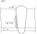
- FIG. 1 schematically shows the positions for measurement of HAZ hardness.
- a circumferentially-welded joint was cut in a plane parallel to the pipe axis.
- hardness was measured at 7 points with a 1.0 mm interval, beginning with the position of 1.5 mm away from the inner surface of the steel pipe toward the outer surface along the wall-thickness direction.
- the maximum hardness measured at the measurement points was treated as the maximum HAZ hardness. The results are shown in the column "Maximum HAZ Hardness" in Table 2.
- the toughness of each produced steel pipe was determined by Charpy impact testing.
- a 2 mm V-notch test specimen (with a cross-sectional area of 10 ⁇ 10 mm (10 ⁇ 8 mm at the notch)) with long sides extending in the longitudinal direction (L direction) of the steel pipe was taken from near central portions of the steel pipe as determined along the wall thickness and testing was conducted at -40 °C.
- the results are shown in the column "Absorbed Energy" in Table 2.
- a material that exhibited an absorbed energy above 100 J during this Charpy impact testing was determined to have high toughness.
- the yield strength was not lower than 555 MPa and the tensile strength was not lower than 625 MPa, and the surface-layer hardness was not higher than 250 Hv.
- the variance of hardness in a given cross section i.e. difference between the surface-layer hardness and the hardness of central portions as determined along the wall thickness
- the maximum HAZ hardness was not higher than 250 Hv. Also, in Charpy impact testing, they had an absorbed energy above 100 J, which means high toughness.
- Item C produced from steel type 3, the yield strength and tensile strength did not satisfy specifications of X80 grade.
- Item D which was produced also from steel type 3 but under different tempering conditions, the specifications of X80 grade were satisfied but the hardness of the surface layers exceeded 250 Hv. Consequently, in Item D, cracks were found in SSC testing.
- Item E produced from steel type 4, the yield strength and tensile strength satisfied the specifications of X80 grade, and the surface-layer hardness was not higher than 250 Hv. However, the variance of the hardness in a given cross section was larger than 15 Hv. The yield strength and tensile strength of Item E were close to their lower limits for X80 grade, and the surface-layer hardness was close to its upper limit for the specifications of ISO 15156. As such, variations in operation conditions may lead to one or more of these specifications not being satisfied. In Item F, which was produced also from steel type 4 but under different tempering conditions, the surface-layer hardness exceeded 250 Hv. Consequently, in Item F, cracks were found in SSC testing.
- Item I produced from steel type 7, the yield strength and tensile strength satisfied the specifications for X80 grade, and the surface-layer hardness was not higher than 250 Hv. However, cracks were produced in HIC testing, and the absorbed energy in Charpy impact testing was below 100 J.
- TP tolerance TP MAX ⁇ TP MIN , where TP MIN is the minimum TP that results in a surface-layer hardness not higher than 250 Hv, and TP MAX is the smaller one of the maximum TP that results in a yield strength not lower than 555 MPa and the maximum TP that results in a tensile strength not lower than 625 MPa.
- the TP tolerance is preferably not less than 200, and more preferably not less than 300, and yet more preferably not less than 400.
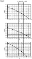
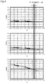
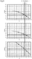
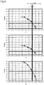
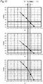
- FIGS. 2 to 11 The results are shown in FIGS. 2 to 11 and in the column "TP Tolerance" in Table 2.
- FIG. 2 shows the relationship between the tempering parameter TP on one hand and yield strength, tensile strength and surface-layer hardness on the other hand for steel type 1.
- FIGS. 3 to 11 each show the relationship between the tempering parameter TP on one hand and yield strength, tensile strength and surface-layer hardness on the other hand for steel types 2 to 10, respectively.
- steel types 1, 2 and 10 which satisfy the preferred conditions specified by the present embodiment had larger TP tolerances than steel types 3 to 9. Thus, even when the operation conditions vary to some degree, both the strength of X80 grade and a hardness not higher than 250 Hv can be provided. Thus, using steel types 1, 2 and 10, a high-strength seamless steel pipe having the above-discussed properties can be produced in an industrially stable manner.
Landscapes
- Chemical & Material Sciences (AREA)
- Engineering & Computer Science (AREA)
- Materials Engineering (AREA)
- Mechanical Engineering (AREA)
- Metallurgy (AREA)
- Organic Chemistry (AREA)
- Physics & Mathematics (AREA)
- Thermal Sciences (AREA)
- Crystallography & Structural Chemistry (AREA)
- Manufacturing & Machinery (AREA)
- Heat Treatment Of Steel (AREA)
- Heat Treatment Of Articles (AREA)
Abstract
Description
- The present invention relates to a high-strength seamless steel pipe and a riser that uses it, and, more particularly, to a high-strength seamless steel pipe suitable for a workover riser and a riser that uses it.
- In recent years, oil and natural-gas resources in on-land and shallow-sea oil fields have been drying up, prompting development in offshore oil fields. In an offshore oil field, crude oil or natural gas must be transported from the pithead of the oil well or natural gas well installed on the seabed to the platform on the sea using a transport steel pipe (or line pipe) known as flow line or riser.
- A flow line is a transport steel pipe laid along the terrain on land or on the seabed. A riser is a transport steel pipe rising from the seabed to the platform on the sea. A flow line or riser laid in the deep sea receives pressures from high-pressure fluids to which deep-formation pressures have been applied. Further, it is affected by deep-sea water pressures when the operation is halted. A riser is further subject to repeated distortions by waves. Accordingly, a flow line or riser is required to have a high strength, where thick-wall steel pipes with wall thicknesses of 30 mm or larger are used.
- A workover riser is used for test operations of oil-well equipment or test production during offshore oil-field development. A workover riser may be in contact with produced fluids during test production. Accordingly, a workover riser is required to have a high strength and, in addition, a certain sour resistance.
- For risers and flow lines, X60 grade steel pipes (with a yield strength of 415 MPa or higher) and X65 grade steel pipes (with a yield strength of 450 MPa or higher) in accordance with the American Petroleum Institute (API) standards are currently used; in addition, X80 grade steel pipes (with a yield strength of 555 MPa or higher) are being developed.
- Japanese Patent No.
4502010 -
JP 2013-32584 A - Japanese Patent
5516831 - Typically, a high-strength seamless steel pipe for line pipe is produced by a heat treatment process with quenching and tempering. In order to achieve a high strength in a thick-wall product, carbon equivalent may be increased to increase hardenability. However, increasing carbon equivalent decreases weldability. Since a line pipe is used after circumferential welding, it is required to have a sufficient weldability. Accordingly, the ingredients of a steel pipe for line pipe are decided so as to provide a lower carbon equivalent than in a steel pipe for oil wells which is deployed without welding, resulting in a low hardenability.
- ISO 15156 stipulates that the hardness of the surface layers of a carbon-steel line pipe which is required to have SSC resistance should be controlled to be 250 Hv or lower. However, since a steel pipe for line pipe has low hardenability, as discussed above, the hardness of central portions as determined along the wall thickness, where the cooling rate is low during quenching, does not easily increase, while the hardness of the surface layers with higher cooling rates is relatively high. This hardness distribution is retained even after tempering. Thus, particularly in a thick-wall steel pipe, it is difficult to control the hardness of the surface layers to be low.
-
JP 2013-32584 A - Japanese Patent Nos.
4502010 5516831 - An object of the present invention is to provide a high-strength seamless steel pipe and riser providing both high strength and low hardness in a stable manner while weldability is maintained.
- A high-strength seamless steel pipe according to an embodiment of the present invention has a chemical composition of, in mass %: 0.10 to 0.18 % C; 0.03 to 1.0 % Si; 0.5 to 2.0 % Mn; up to 0.020 % P; up to 0.0080 % S; 0.10 to 0.60 % Cr; 0.10 to 0.40 % Mo; 0.02 to 0.40 % V; 0.004 to 0.020 % Ti; 0.0005 to 0.005 % B; up to 0.10 % Al; up to 0.008 % N; 0.0004 to 0.0040 % Ca; 0.1 to 1.0 % Cu; 0.2 to 1.0 % Ni; 0 to 0.05 % Nb; and the balance being Fe and impurities, wherein the following formula, F (1), is satisfied:
C+Si/30+(Mn+Cu+Cr)/20+Ni/60+Mo/15+V/10+5×B≤0.28 F (1).
For the element symbols in F (1), the contents of the corresponding elements in mass % are substituted. - The present invention provides a high-strength seamless steel pipe and riser providing both high strength and low hardness in a stable manner while weldability is maintained.
-
-
FIG. 1 schematically shows the positions for measurement of HAZ hardness. -
FIG. 2 shows the relationship between the tempering parameter TP on one hand and yield strength, tensile strength and surface-layer hardness forsteel type 1. -
FIG. 3 shows the relationship between the tempering parameter TP on one hand and yield strength, tensile strength and surface-layer hardness for steel type 2. -
FIG. 4 shows the relationship between the tempering parameter TP on one hand and yield strength, tensile strength and surface-layer hardness for steel type 3. -
FIG. 5 shows the relationship between the tempering parameter TP on one hand and yield strength, tensile strength and surface-layer hardness for steel type 4. -
FIG. 6 shows the relationship between the tempering parameter TP on one hand and yield strength, tensile strength and surface-layer hardness for steel type 5. -
FIG. 7 shows the relationship between the tempering parameter TP on one hand and yield strength, tensile strength and surface-layer hardness for steel type 6. -
FIG. 8 shows the relationship between the tempering parameter TP on one hand and yield strength, tensile strength and surface-layer hardness forsteel type 7. -
FIG. 9 shows the relationship between the tempering parameter TP on one hand and yield strength, tensile strength and surface-layer hardness for steel type 8. -
FIG. 10 shows the relationship between the tempering parameter TP on one hand and yield strength, tensile strength and surface-layer hardness for steel type 9. -
FIG. 11 shows the relationship between the tempering parameter TP on one hand and yield strength, tensile strength and surface-layer hardness for steel type 10. - The present inventors attempted to create a high-strength seamless steel pipe having both high strength and low hardness while maintaining weldability, and obtained the following findings.
- To increase hardenability, a steel product containing 0.10 to 0.18 % carbon (C), which has traditionally not been considered suitable for a steel product for line pipe, is used. Even if a steel product has C in this content range, it provides a weldability required for practical use if PCM, defined by the formula provided below, is 0.28 or smaller. More specifically, if PCM is 0.28 or smaller, the product can be welded without preheating.

- Boron (B) significantly deteriorates weldability, and it is though that B should not be intentionally contained in a steel product for line pipe. However, if B is contained in an appropriate amount that satisfies PCM≤0.28, the hardenability of the steel can be dramatically improved. Further, it is effective if Cu and Ni, which are elements that improve hardenability and whose influence on PCM is relatively small, are contained in predetermined amounts. This will provide a quenched microstructure even in central portions as determined along the wall thickness even in a thick-wall steel pipe, thereby providing both high strength and low hardness.
- By improving the hardenability of the steel pipe, the variance of hardness in a cross section perpendicular to the pipe-axis direction can be reduced. This contributes to the improvement of the toughness of the steel pipe. Reducing the variance of hardness and restricting impurities such as P and S as appropriate provide good toughness.
- The present invention was made based on these findings. The high-strength seamless steel pipe according to an embodiment of the present invention will be described below in detail.
- The high-strength seamless steel pipe according to the present embodiment has the chemical composition described below. In the following description, "%" in the content of an element means mass percent.
- Carbon (C) increases the hardenability of steel. This effect is not sufficiently present if the C content is lower than 0.10 %. On the other hand, if the C content exceeds 0.18 %, the weldability of the steel decreases. In view of this, the C content should be in the range of 0.10 to 0.18 %. The lower limit of C content is preferably 0.12 %. The upper limit of C content is preferably 0.15 %.
- Silicon (Si) deoxidizes steel. This effect is conspicuous if the Si content is 0.03 % or higher. However, if the Si content exceeds 1.0 %, the toughness of the steel decreases. In view of this, the Si content should be in the range of 0.03 to 1.0 %. The lower limit of Si content is preferably 0.05 %, and more preferably 0.10 %. The upper limit of Si content is preferably 0.8 %, and more preferably 0.5 %.
- Manganese (Mn) increases the hardenability of steel. This effect is not sufficiently present if the Mn content is lower than 0.5 %. On the other hand, if the Mn content exceeds 2.0 %, Mn is segregated in the steel, decreasing the toughness of the steel. In view of this, the Mn content should be in the range of 0.5 to 2.0 %. The lower limit of Mn content is preferably 0.6 %. The upper limit of Mn content is preferably 1.5 %, and more preferably 1.0 %.
- Phosphorus (P) is an impurity. P decreases the toughness of the steel. Thus, the lower the P content, the better. In view of this, the P content should be 0.020 % or lower. The P content is preferably not higher than 0.015 %, and more preferably not higher than 0.013 %.
- Sulfur (S) is an impurity. S combines with Mn to form coarse MnS particles, decreasing the toughness and HIC resistance of the steel. Thus, the lower the S content, the better. In view of this, the S content should be 0.0080 % or lower. The S content is preferably not higher than 0.0060 %, and more preferably not higher than 0.0040 %.
- Chromium (Cr) increases the hardenability of steel. Cr further increases the temper-softening resistance of the steel. These effects are not sufficiently present if the Cr content is lower than 0.10 %. On the other hand, if the Cr content exceeds 0.60 %, weldability and HAZ toughness decrease. In view of this, the Cr content should be in the range of 0.10 to 0.60 %. The lower limit of Cr content is preferably 0.20 %, and more preferably 0.25 %, and yet more preferably 0.30 %. The upper limit of Cr content is preferably 0.55 %, and more preferably 0.50 %.
- Molybdenum (Mo) increases hardenability of steel. Mo further combines with C and V in the steel to increase the strength of the steel. These effects are not sufficiently present if the Mo content is lower than 0.10 %. On the other hand, if the Mo content exceeds 0.40 %, the weldability and HAZ toughness of the steel decrease. In view of this, the Mo content should be in the range of 0.10 to 0.40 %. The lower limit of Mo content is preferably 0.20 %, and more preferably 0.25 %. The upper limit of Mo content is preferably 0.35 %.
- Vanadium (V) combines with C in the steel to form V carbides to increase the strength of the steel. This effect is not sufficiently present if the V content is lower than 0.02 %. On the other hand, if the V content is higher than 0.40 %, carbide particles become coarse, decreasing the toughness of the steel. In view of this, the V content should be in the range of 0.02 to 0.40 %. The lower limit of V content is preferably 0.03 %. The upper limit of V content is preferably 0.30 %, and more preferably 0.20 %, and yet more preferably 0.10 %.
- Titanium (Ti) combines with N in the steel to form TiN, minimizing the decrease in the toughness of the steel due to dissolved N. Further, fine dispersed TiN particles that have been deposited increase the toughness of the steel. These effects are not sufficiently present if the Ti content is lower than 0.004 %. On the other hand, if the Ti content is higher than 0.020 %, TiN particles become coarse or coarse TiC particles are formed, decreasing the toughness of the steel. In view of this, the Ti content should be in the range of 0.004 to 0.020 %. The lower limit of Ti content is preferably 0.010 %.
- Boron (B), even in small contents, dramatically improves hardenability. Thus, even in a thick-wall steel pipe, quenched microstructure can be provided even in central portions as determined along the wall thickness, providing both high strength and lower hardness. Further, if B is contained, it widens the ranges of tempering conditions that satisfy predetermined ranges of strength and hardness at the same time. This makes it possible to produce a seamless steel pipe having predetermined ranges of strength and hardness at the same time in an industrially stable manner. The above-discussed effects are not sufficiently present if the B content is lower than 0.0005 %. On the other hand, if an excessive amount of B is contained, weldability rapidly decreases. In view of this, the B content should be in the range of 0.0005 to 0.005 %. The lower limit of B content is preferably 0.0008 %, and more preferably 0.0010 %. The upper limit of B content is preferably 0.0030 %, and more preferably 0.0020 %, and yet more preferably 0.0015 %.
- Aluminum (Al) combines with N to form fine nitride particles, increasing the toughness of the steel. This effect is present if small amounts of Al are contained. On the other hand, if the Al content is higher than 0.10 %, Al nitride particles become coarse, decreasing the toughness of the steel. In view of this, the Al content should be 0.10 % or lower. The lower limit of Al content is preferably 0.001 %, and more preferably 0.01 %. The upper limit of Al content is preferably 0.08 %, and more preferably 0.06 %. Al content as used herein means the content of acid-soluble Al (i.e. so-called Sol-Al).
- Nitrogen (N) combines with Al to form fine Al nitride particles, increasing the toughness of the steel. This effect is present if small amounts of N are contained. On the other hand, if the N content is higher than 0.008 %, dissolved N decreases the toughness of the steel. Further, if the N content is too high, carbonotride particles become coarse, decreasing the toughness of the steel. In view of this, the N content should be 0.008 % or lower. The lower limit of N content is preferably 0.001 %. The upper limit of N content is preferably 0.006 %, and more preferably 0.005 %.
- Calcium (Ca) combines with S in steel to form CaS. As CaS is formed, the formation of MnS is reduced. Thus, Ca increases the toughness and HIC resistance of the steel. It also has the function of preventing alumina-based inclusions from becoming coarse, thereby improving toughness and HIC resistance. These effects are not sufficiently present if the Ca content is lower than 0.0004 %. On the other hand, if the Ca content is higher than 0.0040 %, the index of cleanliness of the steel decreases, decreasing the toughness and HIC resistance of the steel. In view of this, the Ca content should be in the range of 0.0004 to 0.0040 %. The lower limit of Ca content is preferably 0.0005 %, and more preferably 0.0008 %. The upper limit of Ca content is preferably 0.0035 %, and more preferably 0.0030 %.
- Copper (Cu) increases the hardenability of the steel and increases the strength of the steel. This effect is not sufficiently present if the Cu content is lower than 0.1 %. On the other hand, if the Cu content is higher than 1.0 %, the weldability of the steel decreases. Further, if the Cu content is too high, the grain-boundary strength of the steel at high temperatures decreases, decreasing the hot workability of the steel. In view of this, the Cu content should be in the range of 0.1 to 1.0 %. The lower limit of Cu content is preferably 0.12 %, and more preferably 0.15 %. The upper limit of Cu content is preferably 0.5 %, and more preferably 0.3 %, and yet more preferably 0.2 %.
- Nickel (Ni) increases the hardenability of steel and increases the strength of the steel. Further, Ni has only small adverse effects on weldability even though Ni is an element that increases hardenability. Furthermore, Ni improves the toughness of the steel. These effects are not sufficiently present if the Ni content is lower than 0.2 %. On the other hand, if the Ni content is higher than 1.0 %, SSC resistance decreases. In view of this, the Ni content should be in the range of 0.2 to 1.0 %. The lower limit of Ni content is preferably 0.3 %, and more preferably 0.35 %, and yet more preferably 0.4 %. The upper limit of Ni content is preferably 0.9 %, and more preferably 0.8 %.
- The balance of the chemical composition of the high-strength seamless steel pipe according to the present embodiment is Fe and impurities. Impurity as used herein means an element originating from ore or scraps used as raw material for steel or an element that has entered from the environment or the like during the manufacturing process.
- In the chemical composition of the high-strength seamless steel pipe according to the present embodiment, some of the Fe may be replaced by Nb. Nb is an optional element. That is, the chemical composition of the high-strength seamless steel pipe according to the present embodiment may lack Nb.
- Niobium (Nb) combines with C and/or N in steel to form fine Nb carbide particles, increasing the strength and toughness of the steel. Further, Nb dissolves in Mo carbides, preventing Mo carbide particles from becoming coarse. These effects are present if small amounts of Nb are contained. On the other hand, if the Nb content is higher than 0.05 %, carbide particles become coarse, decreasing the toughness of the steel. In view of this, the Nb content should be in the range of 0 to 0.05 %. The lower limit of Nb content is preferably 0.005 %. The upper limit of Nb content is preferably 0.04 %, and more preferably 0.03 %.
- The chemical composition of the high-strength seamless steel pipe for a riser according to the present embodiment satisfies the following formula, F (1):
C+Si/30+(Mn+Cu+Cr)/20+Ni/60+Mo/15+V/10+5×B≤0.28 F (1)
For the element symbols in F (1), the contents of the corresponding elements in mass % are substituted. - The value of the left side of F (1) is referred to as PCM. If PCM is high, weldability can easily decrease or, more particularly, the hardness of welded heat-affected zones (HAZs) can easily increase excessively, or weld cracking can easily occur. In view of this, PCM should be 0.28 or smaller. PCM is preferably not larger than 0.27, and more preferably not larger than 0.26.
- In the chemical composition of the high-strength seamless steel pipe for risers according to the present embodiment, the carbon equivalent Ceq defined by the following formula, F (2), is preferably 0.40 or more:
Ceq=C+Mn/6+(Cr+Mo+V)/5+(Ni+Cu)/15 F (2)
For the element symbols in F (2), the contents of the corresponding elements in mass % are substituted. - The carbon equivalent Ceq is used as in indicator of hardenability. If the carbon equivalent Ceq is too small, sufficient hardenability is not achieved; particularly, in a steel pipe with large wall thickness, the difference between the hardness of surface layers and the hardness of central portions as determined along the wall thickness is large. This makes it difficult to provide both high strength and low hardness. The lower limit of the carbon equivalent Ceq is preferably 0.42, and more preferably 0.45. On the other hand, if the carbon equivalent Ceq is too large, this makes it difficult to provide sufficient weldability. The upper limit of the carbon equivalent Ceq is preferably 0.55, and more preferably 0.50.
- Preferably, the high-strength seamless steel pipe according to the present embodiment has a yield strength of 555 MPa or higher and a tensile strength of 625 MPa or higher. More preferably, the high-strength seamless steel pipe according to the present embodiment has a yield strength of 600 MPa or higher and a tensile strength of 670 MPa or higher.
- In the high-strength seamless steel pipe according to the present embodiment, the hardness of the surface layers is preferably 250 Hv or lower. More particularly, each of the hardness measured at a
position 1 mm from the inner surface of the steel pipe and the hardness measured at aposition 1 mm from the outer surface of the steel pipe is
preferably 250 Hv or lower. Hardness is measured in accordance with JIS Z 2244. More preferably, in the high-strength seamless steel pipe according to the present embodiment, the hardness of the surface layers is 240 Hv or lower. - In the high-strength seamless steel pipe according to the present embodiment, the variance of hardness in a cross section perpendicular to the pipe-axis direction (hereinafter referred to as "variance of hardness in a given cross section") is preferably 15 Hv or smaller. More specifically, the difference between the larger one of the hardness measured at a
position 1 mm from the inner surface of the steel pipe and the hardness measured at aposition 1 mm from the outer surface of the steel pipe and the average hardness in central portions as determined along the wall thickness is preferably 15 Hv or smaller. Average hardness in central portions as determined along the wall thickness is the average of the values measured at four points in central portions as determined along the wall thickness (i.e. 1/2 wall-thickness position). More preferably, in the high-strength seamless steel pipe according to the present embodiment, the variance of hardness in a given cross section is 13 Hv or smaller. - The high-strength seamless steel pipe according to the present embodiment preferably has a wall thickness of 30 mm or larger. The high-strength seamless steel pipe according to the present embodiment preferably has a wall thickness of 35 mm or larger, and more preferably has a wall thickness of 40 mm or larger.
- The high-strength seamless steel pipe according to the present embodiment is suitable for risers. The high-strength seamless steel pipe according to the present embodiment is particularly suitable for workover risers.
- An example of the method of manufacturing the high-strength seamless steel pipe according to the present embodiment will be described below. However, the method of manufacturing the high-strength seamless steel pipe according to the present embodiment is not limited to this example.
- Steel with the above-listed chemical composition is smelted and refined. Subsequently, the steel melt is subjected to continuous casting to produce a billet. Alternatively, a slab or bloom may be produced from the steel melt, and the slab or bloom may be subjected to hot working to produce a billet. The billet is subjected to hot working to produce a hollow shell. More specifically, piercing/rolling, elongation rolling and sizing/rolling are performed to produce a hollow shell.
- The resulting hollow shell is quenched. Quenching is a heat treatment in which a hollow shell is rapidly cooled from the austenite region. The quenching may be so-called direct quenching, i.e. a hot hollow shell after hot working may be rapidly cooled from a temperature that is not lower than the Ar3 point, or the quenching may be so-called in-line quenching, i.e. a hot hollow shell after hot working may be soaked to a temperature that is not lower than the Ac3 point in a supplementary heating furnace and then rapidly cooled. Or, the quenching may be so-called reheat quenching, i.e. a hollow shell may cooled and then reheated to a temperature that is not lower than the Ac3 point and then rapidly cooled.
- The quenched hollow shell is tempered. Tempering usually occurs at a temperature that is not higher than the Ac1 point. The conditions of tempering are adjusted depending on yield strength and hardness. The tempering conditions can be controlled using the following tempering parameter TP:

- The higher the tempering parameter TP during tempering, the lower the yield strength and surface-layer hardness. As discussed above, the high-strength seamless steel pipe preferably has a high yield strength and a low surface-layer hardness. The tempering parameter TP is adjusted to provide the required properties.
- An embodiment of the method of manufacturing a high-strength seamless steel pipe has been described. The high-strength seamless steel pipe according to the present embodiment and a riser using it provide both high strength and low hardness while providing sufficient weldability.
- The present invention will now be described in more detail using inventive examples. The present invention is not limited to these inventive examples.
- Steels with the chemical compositions of
steel types 1 to 10 shown in Table 1 were smelted in a converter furnace, and continuous casting was performed to produce round billets. "-" in Table 1 indicates that the content of the relevant element was at an impurity level. -

-
Steel types 1, 2 and 10 are steels satisfying the preferred conditions of the present embodiment. Steel type 3 is a comparative example selected from steel products for line pipe with common chemical components with low C content and having a carbon equivalent Ceq that is substantially equal to that ofsteel type 1. Steel type 4 is a comparative example selected from steel products for line pipe with common chemical components containing Nb and having a carbon equivalent Ceq that is substantially equal to that ofsteel type 1. Steel type 5 is a comparative example having a C content and a carbon equivalent Ceq that are substantially equal to those ofsteel type 1 and having low B content. Steel type 6 is a comparative example simulating a steel product with high carbon equivalent used for steel pipe for oil wells, for example.Steel type 7 is a comparative example with low Ca content. Steel type 8 is a comparative example with low Cu and Ni contents. Steel type 9 is a comparative example with low Mo content. - The produced round billets were heated in a heating furnace to 1100 to 1300 °C and were subjected to piercing/rolling in a piercing mill. Further, elongation rolling was performed by a mandrel mill and sizing/rolling was performed by a sizer to produce seamless steel pipes with the outer diameters (OD) and wall thicknesses (WT) shown in Table 2. The seamless steel pipes were quenched and tempered under the conditions shown in Table 2 to produce the seamless steel pipes labeled Items A to L.
-
TABLE 2 Item Steel Type OD (mm) WT (mm) Quenching Temp. (°C) Tempering Temp. (°C) Tempering Time (Min.) TP Hardness after Tempering (Hv10kgf) YS (MPa) TS (MPa) HIC SSC Strength-Hardness Balance Maximum HAZ Hardness (Hv10kgf) Absorbed Energy @-40°C(J) Surface Layer Thickness Center Difference TP Tolerance A 1 254.0 42.3 950 680 200 19.558 236 225 11 611 708 No HIC No SSC wide 400 235 190 B 2 241.8 38.0 920 680 120 19,347 233 228 5 602 680 No HIC No SSC wide 430 239 135 C 3 323.9 40.0 950 645 190 18,820 238 199 39 535 609 No HIC No SSC narrow 40 202 333 D 323.9 40.0 950 640 220 18,775 253 212 41 559 642 No HIC SSC narrow 330 E 4 254.0 42.3 950 640 180 18,696 243 219 24 564 645 No HIC No SSC narrow 180 211 310 F 254.0 42.3 950 630 185 18,502 262 217 45 574 651 No HIC SSC narrow 305 G 5 254.0 42.3 950 680 200 19,558 238 211 27 549 650 No HIC No SSC narrow 1 246 205 H 6 272.5 30.4 950 700 135 19,803 240 236 4 619 772 No HIC No SSC wide 510 267 95 I 7 355.6 35.7 950 680 208 19,575 248 246 2 608 695 HIC SSC wide 410 242 62 J 8 254.0 42.3 950 680 114 19,326 258 222 36 598 669 No HIC SSC narrow 20 223 132 K 9 355.6 35.0 950 670 205 19,363 228 211 17 530 600 No HIC No SSC narrow 110 218 196 L 10 355.6 38.1 950 690 135 19.599 243 233 10 615 685 No HIC No SSC wide 610 238 136 - From each seamless steel pipe after tempering, a test specimen for hardness measurement was taken and its hardness was measured in accordance with JIS Z 2244. The higher one of the hardness measured at a
position 1 mm from the inner surface of the steel pipe and the hardness measured at aposition 1 mm from the outer surface of the steel pipe is listed in the column "Surface Layer" in Table 2. The four-point average hardness measured in central portions as determined along the wall thickness is listed in the column "Thickness Center" in Table 2.. The difference between the value of "Surface Layer" and the value of "Thickness Center" is listed in the column "Difference" in Table 2. - From each seamless steel pipe after tempering, an arched test specimen with long sides extending in the longitudinal direction (L-direction) of the steel pipe, defined by ASTM E8/E8M (with a width of 38.1 mm and a gauge-mark distance of 50.8 mm), was taken. The test specimen taken was used to perform tensile testing in the atmosphere at room temperature (25 °C) to determine the yield stress and tensile strength. The yield stress was calculated by the 0.5 % total-elongation method. The yield stress is listed in the column "YS" in Table 2 and the tensile strength is listed in the column "TS".
- From each seamless steel pipe after tempering, a test specimen including a portion of the inner surface, a test specimen including a central portion as determined along the wall thickness, and a test specimen including a portion of the outer surface were taken. Each test specimen had a thickness of 30 mm, a width (circumferential) of 20 mm, and a length 100 mm. The HIC resistance of each test specimen was evaluated in accordance with NACE TM 0284-2003. The testing bath was a 5 % NaCl + 0.5 % acetic acid-water solution at room temperature, saturated with 1 atm hydrogen sulfide gas. 96 hours after each specimen was immersed, the specimen was cut into three equal parts arranged in the longitudinal direction, and the presence or absence of cracks was visually determined. Further, in each test specimen including a portion of the inner surface of the steel pipe, the presence or absence of cracks was determined by ultrasonic inspection testing.
- The results are shown in the column "HIC" in Table 2. "No HIC" in the column "HIC" indicates that no cracks were found. "HIC" indicates that cracks were found.
- From each seamless steel pipe after tempering, a test specimen including a portion of the inner surface, a test specimen including a central portion as determined in the wall thickness, and a test specimen including a portion of the outer surface were taken. Each test specimen had a thickness of 2 mm, a width (circumferential) of 20 mm, and a length of 100 mm. These test specimens were immersed in the same NACE testing bath as for the above-discussed HIC testing for 720 hours, where each test specimen had a stress of 90 % of its yield strength applied thereto. After the immersion, the presence or absence of cracks were determined in the test specimens.
- The results are shown in the column "SSC" in Table 2. "No SSC" in the column "SSC" indicates that no cracks were found in any of the test specimens. "SSC" indicates that cracks were found in one of the test specimens.
- Each seamless steel pipe after tempering was used to make a circumferentially welded joint, and HAZ hardness testing was conducted. The groove shape was 5 ° narrow groove, and the welding process was gas metal arc welding (GMAW), and the welding conditions were as follows: the heat input during welding was 1.0 kJ/mm, the preheating/interlayer temperature was 200 to 250 °C, and the shield gas was diargon (80 volume % Ar + 20 volume % CO2).
-
FIG. 1 schematically shows the positions for measurement of HAZ hardness. A circumferentially-welded joint was cut in a plane parallel to the pipe axis. At a position 0.3 mm distant from the fusion line (FL), hardness was measured at 7 points with a 1.0 mm interval, beginning with the position of 1.5 mm away from the inner surface of the steel pipe toward the outer surface along the wall-thickness direction. The maximum hardness measured at the measurement points was treated as the maximum HAZ hardness. The results are shown in the column "Maximum HAZ Hardness" in Table 2. - The toughness of each produced steel pipe was determined by Charpy impact testing. A 2 mm V-notch test specimen (with a cross-sectional area of 10×10 mm (10×8 mm at the notch)) with long sides extending in the longitudinal direction (L direction) of the steel pipe was taken from near central portions of the steel pipe as determined along the wall thickness and testing was conducted at -40 °C. The results are shown in the column "Absorbed Energy" in Table 2. A material that exhibited an absorbed energy above 100 J during this Charpy impact testing was determined to have high toughness.
- As shown in Table 2, in each of Items A, B and L which were produced from
steel types 1, 2 and 10 which satisfied the preferred conditions of the present embodiment, the yield strength was not lower than 555 MPa and the tensile strength was not lower than 625 MPa, and the surface-layer hardness was not higher than 250 Hv. Further, in each of Items A, B and L the variance of hardness in a given cross section (i.e. difference between the surface-layer hardness and the hardness of central portions as determined along the wall thickness) was not higher than 15 Hv. Further, in each of Items A, B and L the maximum HAZ hardness was not higher than 250 Hv. Also, in Charpy impact testing, they had an absorbed energy above 100 J, which means high toughness. - In Item C produced from steel type 3, the yield strength and tensile strength did not satisfy specifications of X80 grade. In Item D, which was produced also from steel type 3 but under different tempering conditions, the specifications of X80 grade were satisfied but the hardness of the surface layers exceeded 250 Hv. Consequently, in Item D, cracks were found in SSC testing.
- In Item E produced from steel type 4, the yield strength and tensile strength satisfied the specifications of X80 grade, and the surface-layer hardness was not higher than 250 Hv. However, the variance of the hardness in a given cross section was larger than 15 Hv. The yield strength and tensile strength of Item E were close to their lower limits for X80 grade, and the surface-layer hardness was close to its upper limit for the specifications of ISO 15156. As such, variations in operation conditions may lead to one or more of these specifications not being satisfied. In Item F, which was produced also from steel type 4 but under different tempering conditions, the surface-layer hardness exceeded 250 Hv. Consequently, in Item F, cracks were found in SSC testing.
- In Item G produced from steel type 5, the yield strength did not satisfy the specifications of X80 grade.
- In Item H produced from steel type 6, the yield strength and tensile strength satisfied the specifications for X80 grade and the surface-layer hardness was not higher than 250 Hv. However, the maximum HAZ hardness exceeded 260 Hv, which is a high value. The absorbed energy from Charpy impact testing was below 100 J.
- In Item I produced from
steel type 7, the yield strength and tensile strength satisfied the specifications for X80 grade, and the surface-layer hardness was not higher than 250 Hv. However, cracks were produced in HIC testing, and the absorbed energy in Charpy impact testing was below 100 J. - In Item J produced from steel pipe 8, the surface-layer hardness exceeded 250 Hv. Thus, cracks were found in Item J in the SSC test.
- In Item K produced from steel pipe 9, the yield strength did not satisfy the provisions of X80 grade.
- For each of
steel types 1 to 10, seamless steel pipes were produced under different tempering conditions, and the yield strength, tensile strength and the hardness of the surface layers were measured. From the measurements, the relationship between the tempering parameter TP and these properties was determined by regression analysis. Then, the range of TP where all of the three conditions of a yield strength not lower than 555 MPa, a tensile strength not lower than 625 MPa and a surface-layer hardness not higher than 250 Hv were satisfied (i.e. TP tolerance) was determined. - More specifically, the TP tolerance is defined by the following formula:

- If the TP tolerance is wide, both the strength of X80 grade and a hardness of 250 Hv or lower can be provided even when operation conditions vary to some degree. This will enable producing the high-strength seamless steel pipe exhibiting the above-indicated properties in an industrially stable manner. The TP tolerance is preferably not less than 200, and more preferably not less than 300, and yet more preferably not less than 400.
- The results are shown in
FIGS. 2 to 11 and in the column "TP Tolerance" in Table 2.FIG. 2 shows the relationship between the tempering parameter TP on one hand and yield strength, tensile strength and surface-layer hardness on the other hand forsteel type 1. Similarly,FIGS. 3 to 11 each show the relationship between the tempering parameter TP on one hand and yield strength, tensile strength and surface-layer hardness on the other hand for steel types 2 to 10, respectively. - As shown in
FIGS. 2 to 11 and Table 2,steel types 1, 2 and 10, which satisfy the preferred conditions specified by the present embodiment had larger TP tolerances than steel types 3 to 9. Thus, even when the operation conditions vary to some degree, both the strength of X80 grade and a hardness not higher than 250 Hv can be provided. Thus, usingsteel types 1, 2 and 10, a high-strength seamless steel pipe having the above-discussed properties can be produced in an industrially stable manner. - An embodiment of the present invention has been described. The above-described embodiment is merely an example for carrying out the present invention. Thus, the present invention is not limited to the above-described embodiment, and the above-described embodiment can be modified appropriately without departing from the spirit of the present invention.
Claims (5)
- A high-strength seamless steel pipe having a chemical composition of, in mass %:0.10 to 0.18 % C;0.03 to 1.0 % Si;0.5 to 2.0 % Mn;up to 0.020 % P;up to 0.0080 % S;0.10 to 0.60 % Cr;0.10 to 0.40 % Mo;0.02 to 0.40 % V;0.004 to 0.020 % Ti;0.0005 to 0.005 % B;up to 0.10 % Al;up to 0.008 % N;0.0004 to 0.0040 % Ca;0.1 to 1.0 % Cu;0.2 to 1.0 % Ni;0 to 0.05 % Nb; andthe balance being Fe and impurities,
wherein the following formula, F (1), is satisfied:
C+Si/30+(Mn+Cu+Cr)/20+Ni/60+Mo/15+V/10+5×B≤0.28 F (1),
wherein, for the element symbols in F (1), the contents of the corresponding elements in mass % are substituted. - The high-strength seamless steel pipe according to claim 1, wherein the chemical composition includes, in mass %:
0.005 to 0.05 % Nb. - The high-strength seamless steel pipe according to claim 1 or 2, wherein:the pipe has a wall thickness of 30 mm or larger,the pipe has a yield strength of 555 MPa or higher and a tensile strength of 625 MPa or higher, anda hardness of surface layers is 250 Hv or lower.
- The high-strength seamless steel pipe according to any one of claims 1 to 3, wherein a variance of hardness in a cross section perpendicular to a pipe-axis direction is 15 Hv or smaller.
- A riser composed of the high-strength seamless steel pipe according to any one of claims 1 to 4.
Applications Claiming Priority (2)
| Application Number | Priority Date | Filing Date | Title |
|---|---|---|---|
| JP2016148646 | 2016-07-28 | ||
| PCT/JP2017/024739 WO2018020972A1 (en) | 2016-07-28 | 2017-07-05 | High strength seamless steel pipe and riser |
Publications (3)
| Publication Number | Publication Date |
|---|---|
| EP3492612A1 true EP3492612A1 (en) | 2019-06-05 |
| EP3492612A4 EP3492612A4 (en) | 2019-08-07 |
| EP3492612B1 EP3492612B1 (en) | 2025-05-21 |
Family
ID=61016070
Family Applications (1)
| Application Number | Title | Priority Date | Filing Date |
|---|---|---|---|
| EP17833981.8A Active EP3492612B1 (en) | 2016-07-28 | 2017-07-05 | High strength seamless steel pipe and riser |
Country Status (6)
| Country | Link |
|---|---|
| EP (1) | EP3492612B1 (en) |
| JP (1) | JP6642715B2 (en) |
| AR (1) | AR109055A1 (en) |
| BR (1) | BR112018015533A2 (en) |
| MX (1) | MX2018011404A (en) |
| WO (1) | WO2018020972A1 (en) |
Cited By (1)
| Publication number | Priority date | Publication date | Assignee | Title |
|---|---|---|---|---|
| EP4596129A4 (en) * | 2022-09-30 | 2026-01-07 | Nippon Steel Corp | STEEL PLATE |
Families Citing this family (3)
| Publication number | Priority date | Publication date | Assignee | Title |
|---|---|---|---|---|
| JP6891828B2 (en) * | 2018-01-25 | 2021-06-18 | 日本製鉄株式会社 | High-strength seamless steel pipe and jack-up rig bracing pipe |
| CN111187982A (en) * | 2020-02-17 | 2020-05-22 | 本钢板材股份有限公司 | Low-yield-ratio spiral welded pipe steel A139Gr.B and preparation method thereof |
| JP7464900B1 (en) | 2022-10-03 | 2024-04-10 | 日本製鉄株式会社 | Seamless steel pipe and method for manufacturing seamless steel pipe |
Family Cites Families (10)
| Publication number | Priority date | Publication date | Assignee | Title |
|---|---|---|---|---|
| JPS575819A (en) * | 1980-06-13 | 1982-01-12 | Nippon Kokan Kk <Nkk> | Preparation of seamless line pipe having excellent sulfide hydrogen cracking resistance |
| JPS61238917A (en) * | 1985-04-15 | 1986-10-24 | Kawasaki Steel Corp | Manufacture of low alloy tempered high tensile seamless steel pipe |
| JP3975852B2 (en) * | 2001-10-25 | 2007-09-12 | Jfeスチール株式会社 | Steel pipe excellent in workability and manufacturing method thereof |
| JP2004176172A (en) * | 2002-10-01 | 2004-06-24 | Sumitomo Metal Ind Ltd | High-strength seamless steel pipe excellent in resistance to hydrogen-induced cracking and its manufacturing method |
| JP4945946B2 (en) * | 2005-07-26 | 2012-06-06 | 住友金属工業株式会社 | Seamless steel pipe and manufacturing method thereof |
| JP5326344B2 (en) * | 2007-04-27 | 2013-10-30 | 新日鐵住金株式会社 | Heat-resistant structure with excellent creep characteristics in heat-affected zone |
| WO2010061882A1 (en) * | 2008-11-26 | 2010-06-03 | 住友金属工業株式会社 | Seamless steel pipe and method for manufacturing same |
| JP6047947B2 (en) * | 2011-06-30 | 2016-12-21 | Jfeスチール株式会社 | Thick high-strength seamless steel pipe for line pipes with excellent sour resistance and method for producing the same |
| IN2014DN09528A (en) * | 2012-04-27 | 2015-07-17 | Nippon Steel & Sumitomo Metal Corp | |
| AU2014303873B2 (en) * | 2013-08-06 | 2017-06-08 | Nippon Steel Corporation | Seamless steel pipe for line pipe, and method for producing same |
-
2017
- 2017-07-05 WO PCT/JP2017/024739 patent/WO2018020972A1/en not_active Ceased
- 2017-07-05 JP JP2018529468A patent/JP6642715B2/en active Active
- 2017-07-05 MX MX2018011404A patent/MX2018011404A/en unknown
- 2017-07-05 EP EP17833981.8A patent/EP3492612B1/en active Active
- 2017-07-05 BR BR112018015533-0A patent/BR112018015533A2/en not_active Application Discontinuation
- 2017-07-14 AR ARP170101966A patent/AR109055A1/en active IP Right Grant
Cited By (1)
| Publication number | Priority date | Publication date | Assignee | Title |
|---|---|---|---|---|
| EP4596129A4 (en) * | 2022-09-30 | 2026-01-07 | Nippon Steel Corp | STEEL PLATE |
Also Published As
| Publication number | Publication date |
|---|---|
| BR112018015533A2 (en) | 2018-12-26 |
| WO2018020972A1 (en) | 2018-02-01 |
| EP3492612A4 (en) | 2019-08-07 |
| EP3492612B1 (en) | 2025-05-21 |
| JPWO2018020972A1 (en) | 2018-11-01 |
| AR109055A1 (en) | 2018-10-24 |
| JP6642715B2 (en) | 2020-02-12 |
| MX2018011404A (en) | 2019-03-28 |
Similar Documents
| Publication | Publication Date | Title |
|---|---|---|
| EP2492361B1 (en) | High strength steel pipe with excellent toughness at low temperature and good sulfide stress corrosion cracking resistance | |
| EP2484784B1 (en) | Heavy wall steel pipes with excellent toughness at low temperature and sulfide stress corrosion cracking resistance | |
| EP1546417B1 (en) | High strength seamless steel pipe excellent in hydrogen-induced cracking resistance and its production method | |
| JP4502011B2 (en) | Seamless steel pipe for line pipe and its manufacturing method | |
| EP2824198B1 (en) | Method for producing seamless steel pipe having high-strength and excellent sulfide stress cracking resistance | |
| JP4969915B2 (en) | Steel tube for high-strength line pipe excellent in strain aging resistance, steel plate for high-strength line pipe, and production method thereof | |
| CN102906292B (en) | Line-pipes weldless steel tube and manufacture method thereof | |
| CN108699644B (en) | Seamless steel pipe and manufacturing method thereof | |
| EP3636787B1 (en) | Bent steel pipe and method for producing same | |
| JP5499575B2 (en) | Martensitic stainless steel seamless pipe for oil well pipe and method for producing the same | |
| KR102450006B1 (en) | Microalloy steel and method for producing said steel | |
| EP3492612B1 (en) | High strength seamless steel pipe and riser | |
| JP4250851B2 (en) | Martensitic stainless steel and manufacturing method | |
| JP2023022159A (en) | Steel composition meeting X-65 grade API 5L PSL-2 specification with enhanced resistance to hydrogen-induced cracking (HIC) and method for producing same | |
| EP3330398B1 (en) | Steel pipe for line pipe and method for manufacturing same | |
| KR20170128575A (en) | Steel plate for structural pipe, method for producing steel plate for structural pipe, and structural pipe | |
| KR102031455B1 (en) | Hot-rolled steel sheet having excellent low temperature toughness, steel pipe using the steel sheet and method for manufacturing thereof | |
| KR102719164B1 (en) | Hot-rolled steel sheet and method of manufacturing the same |
Legal Events
| Date | Code | Title | Description |
|---|---|---|---|
| STAA | Information on the status of an ep patent application or granted ep patent |
Free format text: STATUS: THE INTERNATIONAL PUBLICATION HAS BEEN MADE |
|
| PUAI | Public reference made under article 153(3) epc to a published international application that has entered the european phase |
Free format text: ORIGINAL CODE: 0009012 |
|
| STAA | Information on the status of an ep patent application or granted ep patent |
Free format text: STATUS: REQUEST FOR EXAMINATION WAS MADE |
|
| 17P | Request for examination filed |
Effective date: 20180711 |
|
| AK | Designated contracting states |
Kind code of ref document: A1 Designated state(s): AL AT BE BG CH CY CZ DE DK EE ES FI FR GB GR HR HU IE IS IT LI LT LU LV MC MK MT NL NO PL PT RO RS SE SI SK SM TR |
|
| AX | Request for extension of the european patent |
Extension state: BA ME |
|
| A4 | Supplementary search report drawn up and despatched |
Effective date: 20190710 |
|
| RIC1 | Information provided on ipc code assigned before grant |
Ipc: C22C 38/04 20060101ALI20190704BHEP Ipc: C21D 8/10 20060101ALI20190704BHEP Ipc: C22C 38/46 20060101ALI20190704BHEP Ipc: C22C 38/48 20060101ALI20190704BHEP Ipc: C22C 38/02 20060101ALI20190704BHEP Ipc: C22C 38/00 20060101AFI20190704BHEP Ipc: C21D 9/08 20060101ALI20190704BHEP Ipc: C22C 38/54 20060101ALI20190704BHEP Ipc: C21D 6/00 20060101ALI20190704BHEP Ipc: C22C 38/42 20060101ALI20190704BHEP Ipc: C22C 38/58 20060101ALI20190704BHEP Ipc: C22C 38/44 20060101ALI20190704BHEP Ipc: C22C 38/50 20060101ALI20190704BHEP Ipc: C22C 38/06 20060101ALI20190704BHEP |
|
| RAP1 | Party data changed (applicant data changed or rights of an application transferred) |
Owner name: NIPPON STEEL CORPORATION |
|
| DAV | Request for validation of the european patent (deleted) | ||
| DAX | Request for extension of the european patent (deleted) | ||
| GRAP | Despatch of communication of intention to grant a patent |
Free format text: ORIGINAL CODE: EPIDOSNIGR1 |
|
| STAA | Information on the status of an ep patent application or granted ep patent |
Free format text: STATUS: GRANT OF PATENT IS INTENDED |
|
| INTG | Intention to grant announced |
Effective date: 20250303 |
|
| GRAS | Grant fee paid |
Free format text: ORIGINAL CODE: EPIDOSNIGR3 |
|
| GRAA | (expected) grant |
Free format text: ORIGINAL CODE: 0009210 |
|
| STAA | Information on the status of an ep patent application or granted ep patent |
Free format text: STATUS: THE PATENT HAS BEEN GRANTED |
|
| AK | Designated contracting states |
Kind code of ref document: B1 Designated state(s): AL AT BE BG CH CY CZ DE DK EE ES FI FR GB GR HR HU IE IS IT LI LT LU LV MC MK MT NL NO PL PT RO RS SE SI SK SM TR |
|
| REG | Reference to a national code |
Ref country code: GB Ref legal event code: FG4D |
|
| REG | Reference to a national code |
Ref country code: CH Ref legal event code: EP |
|
| REG | Reference to a national code |
Ref country code: DE Ref legal event code: R096 Ref document number: 602017089591 Country of ref document: DE |
|
| REG | Reference to a national code |
Ref country code: IE Ref legal event code: FG4D |
|
| REG | Reference to a national code |
Ref country code: NL Ref legal event code: MP Effective date: 20250521 |
|
| PG25 | Lapsed in a contracting state [announced via postgrant information from national office to epo] |
Ref country code: PT Free format text: LAPSE BECAUSE OF FAILURE TO SUBMIT A TRANSLATION OF THE DESCRIPTION OR TO PAY THE FEE WITHIN THE PRESCRIBED TIME-LIMIT Effective date: 20250922 Ref country code: FI Free format text: LAPSE BECAUSE OF FAILURE TO SUBMIT A TRANSLATION OF THE DESCRIPTION OR TO PAY THE FEE WITHIN THE PRESCRIBED TIME-LIMIT Effective date: 20250521 Ref country code: ES Free format text: LAPSE BECAUSE OF FAILURE TO SUBMIT A TRANSLATION OF THE DESCRIPTION OR TO PAY THE FEE WITHIN THE PRESCRIBED TIME-LIMIT Effective date: 20250521 |
|
| REG | Reference to a national code |
Ref country code: LT Ref legal event code: MG9D |
|
| PG25 | Lapsed in a contracting state [announced via postgrant information from national office to epo] |
Ref country code: GR Free format text: LAPSE BECAUSE OF FAILURE TO SUBMIT A TRANSLATION OF THE DESCRIPTION OR TO PAY THE FEE WITHIN THE PRESCRIBED TIME-LIMIT Effective date: 20250822 Ref country code: NO Free format text: LAPSE BECAUSE OF FAILURE TO SUBMIT A TRANSLATION OF THE DESCRIPTION OR TO PAY THE FEE WITHIN THE PRESCRIBED TIME-LIMIT Effective date: 20250821 |
|
| PG25 | Lapsed in a contracting state [announced via postgrant information from national office to epo] |
Ref country code: NL Free format text: LAPSE BECAUSE OF FAILURE TO SUBMIT A TRANSLATION OF THE DESCRIPTION OR TO PAY THE FEE WITHIN THE PRESCRIBED TIME-LIMIT Effective date: 20250521 Ref country code: PL Free format text: LAPSE BECAUSE OF FAILURE TO SUBMIT A TRANSLATION OF THE DESCRIPTION OR TO PAY THE FEE WITHIN THE PRESCRIBED TIME-LIMIT Effective date: 20250521 |
|
| PG25 | Lapsed in a contracting state [announced via postgrant information from national office to epo] |
Ref country code: BG Free format text: LAPSE BECAUSE OF FAILURE TO SUBMIT A TRANSLATION OF THE DESCRIPTION OR TO PAY THE FEE WITHIN THE PRESCRIBED TIME-LIMIT Effective date: 20250521 |
|
| PG25 | Lapsed in a contracting state [announced via postgrant information from national office to epo] |
Ref country code: HR Free format text: LAPSE BECAUSE OF FAILURE TO SUBMIT A TRANSLATION OF THE DESCRIPTION OR TO PAY THE FEE WITHIN THE PRESCRIBED TIME-LIMIT Effective date: 20250521 |
|
| PG25 | Lapsed in a contracting state [announced via postgrant information from national office to epo] |
Ref country code: RS Free format text: LAPSE BECAUSE OF FAILURE TO SUBMIT A TRANSLATION OF THE DESCRIPTION OR TO PAY THE FEE WITHIN THE PRESCRIBED TIME-LIMIT Effective date: 20250821 |
|
| PG25 | Lapsed in a contracting state [announced via postgrant information from national office to epo] |
Ref country code: IS Free format text: LAPSE BECAUSE OF FAILURE TO SUBMIT A TRANSLATION OF THE DESCRIPTION OR TO PAY THE FEE WITHIN THE PRESCRIBED TIME-LIMIT Effective date: 20250921 |
|
| PG25 | Lapsed in a contracting state [announced via postgrant information from national office to epo] |
Ref country code: LV Free format text: LAPSE BECAUSE OF FAILURE TO SUBMIT A TRANSLATION OF THE DESCRIPTION OR TO PAY THE FEE WITHIN THE PRESCRIBED TIME-LIMIT Effective date: 20250521 |
|
| REG | Reference to a national code |
Ref country code: AT Ref legal event code: MK05 Ref document number: 1796809 Country of ref document: AT Kind code of ref document: T Effective date: 20250521 |
|
| PG25 | Lapsed in a contracting state [announced via postgrant information from national office to epo] |
Ref country code: AT Free format text: LAPSE BECAUSE OF FAILURE TO SUBMIT A TRANSLATION OF THE DESCRIPTION OR TO PAY THE FEE WITHIN THE PRESCRIBED TIME-LIMIT Effective date: 20250521 Ref country code: SM Free format text: LAPSE BECAUSE OF FAILURE TO SUBMIT A TRANSLATION OF THE DESCRIPTION OR TO PAY THE FEE WITHIN THE PRESCRIBED TIME-LIMIT Effective date: 20250521 Ref country code: DK Free format text: LAPSE BECAUSE OF FAILURE TO SUBMIT A TRANSLATION OF THE DESCRIPTION OR TO PAY THE FEE WITHIN THE PRESCRIBED TIME-LIMIT Effective date: 20250521 |
|
| PG25 | Lapsed in a contracting state [announced via postgrant information from national office to epo] |
Ref country code: CZ Free format text: LAPSE BECAUSE OF FAILURE TO SUBMIT A TRANSLATION OF THE DESCRIPTION OR TO PAY THE FEE WITHIN THE PRESCRIBED TIME-LIMIT Effective date: 20250521 |
|
| PG25 | Lapsed in a contracting state [announced via postgrant information from national office to epo] |
Ref country code: EE Free format text: LAPSE BECAUSE OF FAILURE TO SUBMIT A TRANSLATION OF THE DESCRIPTION OR TO PAY THE FEE WITHIN THE PRESCRIBED TIME-LIMIT Effective date: 20250521 |
|
| PG25 | Lapsed in a contracting state [announced via postgrant information from national office to epo] |
Ref country code: SK Free format text: LAPSE BECAUSE OF FAILURE TO SUBMIT A TRANSLATION OF THE DESCRIPTION OR TO PAY THE FEE WITHIN THE PRESCRIBED TIME-LIMIT Effective date: 20250521 Ref country code: RO Free format text: LAPSE BECAUSE OF FAILURE TO SUBMIT A TRANSLATION OF THE DESCRIPTION OR TO PAY THE FEE WITHIN THE PRESCRIBED TIME-LIMIT Effective date: 20250521 |
|
| REG | Reference to a national code |
Ref country code: DE Ref legal event code: R119 Ref document number: 602017089591 Country of ref document: DE |
|
| REG | Reference to a national code |
Ref country code: CH Ref legal event code: H13 Free format text: ST27 STATUS EVENT CODE: U-0-0-H10-H13 (AS PROVIDED BY THE NATIONAL OFFICE) Effective date: 20260224 |
|
| PG25 | Lapsed in a contracting state [announced via postgrant information from national office to epo] |
Ref country code: LU Free format text: LAPSE BECAUSE OF NON-PAYMENT OF DUE FEES Effective date: 20250705 |
|
| REG | Reference to a national code |
Ref country code: BE Ref legal event code: MM Effective date: 20250731 |
|
| PLBE | No opposition filed within time limit |
Free format text: ORIGINAL CODE: 0009261 |
|
| STAA | Information on the status of an ep patent application or granted ep patent |
Free format text: STATUS: NO OPPOSITION FILED WITHIN TIME LIMIT |
|
| REG | Reference to a national code |
Ref country code: CH Ref legal event code: L10 Free format text: ST27 STATUS EVENT CODE: U-0-0-L10-L00 (AS PROVIDED BY THE NATIONAL OFFICE) Effective date: 20260402 |
|
| PG25 | Lapsed in a contracting state [announced via postgrant information from national office to epo] |
Ref country code: DE Free format text: LAPSE BECAUSE OF NON-PAYMENT OF DUE FEES Effective date: 20260203 |
|
| PG25 | Lapsed in a contracting state [announced via postgrant information from national office to epo] |
Ref country code: BE Free format text: LAPSE BECAUSE OF NON-PAYMENT OF DUE FEES Effective date: 20250731 |
|
| PG25 | Lapsed in a contracting state [announced via postgrant information from national office to epo] |
Ref country code: FR Free format text: LAPSE BECAUSE OF NON-PAYMENT OF DUE FEES Effective date: 20250721 |
|
| PG25 | Lapsed in a contracting state [announced via postgrant information from national office to epo] |
Ref country code: CH Free format text: LAPSE BECAUSE OF NON-PAYMENT OF DUE FEES Effective date: 20250731 |
|
| 26N | No opposition filed |
Effective date: 20260224 |
|
| GBPC | Gb: european patent ceased through non-payment of renewal fee |
Effective date: 20250821 |
|
| PG25 | Lapsed in a contracting state [announced via postgrant information from national office to epo] |
Ref country code: LT Free format text: LAPSE BECAUSE OF FAILURE TO SUBMIT A TRANSLATION OF THE DESCRIPTION OR TO PAY THE FEE WITHIN THE PRESCRIBED TIME-LIMIT Effective date: 20250521 |
|
| PG25 | Lapsed in a contracting state [announced via postgrant information from national office to epo] |
Ref country code: GB Free format text: LAPSE BECAUSE OF NON-PAYMENT OF DUE FEES Effective date: 20250821 |
|
| PGFP | Annual fee paid to national office [announced via postgrant information from national office to epo] |
Ref country code: IT Payment date: 20260622 Year of fee payment: 10 |
|
| PG25 | Lapsed in a contracting state [announced via postgrant information from national office to epo] |
Ref country code: IE Free format text: LAPSE BECAUSE OF NON-PAYMENT OF DUE FEES Effective date: 20250705 |
|
| PG25 | Lapsed in a contracting state [announced via postgrant information from national office to epo] |
Ref country code: MC Free format text: LAPSE BECAUSE OF FAILURE TO SUBMIT A TRANSLATION OF THE DESCRIPTION OR TO PAY THE FEE WITHIN THE PRESCRIBED TIME-LIMIT Effective date: 20250521 |
|
| PG25 | Lapsed in a contracting state [announced via postgrant information from national office to epo] |
Ref country code: SE Free format text: LAPSE BECAUSE OF FAILURE TO SUBMIT A TRANSLATION OF THE DESCRIPTION OR TO PAY THE FEE WITHIN THE PRESCRIBED TIME-LIMIT Effective date: 20250521 Ref country code: CY Free format text: LAPSE BECAUSE OF FAILURE TO SUBMIT A TRANSLATION OF THE DESCRIPTION OR TO PAY THE FEE WITHIN THE PRESCRIBED TIME-LIMIT Effective date: 20250521 |