EP3492573A1 - Test device - Google Patents
Test device Download PDFInfo
- Publication number
- EP3492573A1 EP3492573A1 EP17834225.9A EP17834225A EP3492573A1 EP 3492573 A1 EP3492573 A1 EP 3492573A1 EP 17834225 A EP17834225 A EP 17834225A EP 3492573 A1 EP3492573 A1 EP 3492573A1
- Authority
- EP
- European Patent Office
- Prior art keywords
- housing
- lid
- container
- support
- hole
- Prior art date
- Legal status (The legal status is an assumption and is not a legal conclusion. Google has not performed a legal analysis and makes no representation as to the accuracy of the status listed.)
- Pending
Links
- 238000012360 testing method Methods 0.000 title claims abstract description 152
- 239000007788 liquid Substances 0.000 claims abstract description 184
- 238000004587 chromatography analysis Methods 0.000 claims abstract description 154
- 230000001681 protective effect Effects 0.000 claims description 11
- 230000007246 mechanism Effects 0.000 claims description 7
- 238000002834 transmittance Methods 0.000 claims description 6
- 238000013508 migration Methods 0.000 abstract description 11
- 230000005012 migration Effects 0.000 abstract description 11
- 238000011109 contamination Methods 0.000 abstract description 8
- 238000001514 detection method Methods 0.000 description 65
- 230000002093 peripheral effect Effects 0.000 description 27
- 238000002372 labelling Methods 0.000 description 21
- 239000003795 chemical substances by application Substances 0.000 description 20
- 108020004707 nucleic acids Proteins 0.000 description 17
- 150000007523 nucleic acids Chemical class 0.000 description 17
- 102000039446 nucleic acids Human genes 0.000 description 17
- 239000000463 material Substances 0.000 description 12
- 238000010521 absorption reaction Methods 0.000 description 9
- 238000011161 development Methods 0.000 description 9
- 238000000034 method Methods 0.000 description 9
- 239000000758 substrate Substances 0.000 description 9
- 230000000007 visual effect Effects 0.000 description 9
- 238000013459 approach Methods 0.000 description 8
- 230000008569 process Effects 0.000 description 7
- 239000000126 substance Substances 0.000 description 7
- 229910052751 metal Inorganic materials 0.000 description 6
- 239000002184 metal Substances 0.000 description 6
- 239000011347 resin Substances 0.000 description 6
- 229920005989 resin Polymers 0.000 description 6
- 239000012528 membrane Substances 0.000 description 5
- 230000003321 amplification Effects 0.000 description 4
- 239000000975 dye Substances 0.000 description 4
- 230000000694 effects Effects 0.000 description 4
- 230000004907 flux Effects 0.000 description 4
- 238000003199 nucleic acid amplification method Methods 0.000 description 4
- 239000002245 particle Substances 0.000 description 4
- VYPSYNLAJGMNEJ-UHFFFAOYSA-N Silicium dioxide Chemical compound O=[Si]=O VYPSYNLAJGMNEJ-UHFFFAOYSA-N 0.000 description 3
- 239000000427 antigen Substances 0.000 description 3
- 102000036639 antigens Human genes 0.000 description 3
- 108091007433 antigens Proteins 0.000 description 3
- 230000005489 elastic deformation Effects 0.000 description 3
- 239000000499 gel Substances 0.000 description 3
- 230000000630 rising effect Effects 0.000 description 3
- 210000003934 vacuole Anatomy 0.000 description 3
- 239000011534 wash buffer Substances 0.000 description 3
- 239000000872 buffer Substances 0.000 description 2
- 235000019646 color tone Nutrition 0.000 description 2
- 238000004891 communication Methods 0.000 description 2
- 239000006185 dispersion Substances 0.000 description 2
- 239000012530 fluid Substances 0.000 description 2
- 239000011521 glass Substances 0.000 description 2
- 150000004676 glycans Chemical class 0.000 description 2
- 229910052500 inorganic mineral Inorganic materials 0.000 description 2
- 230000033001 locomotion Effects 0.000 description 2
- 239000011707 mineral Substances 0.000 description 2
- 239000000203 mixture Substances 0.000 description 2
- -1 plate Substances 0.000 description 2
- BASFCYQUMIYNBI-UHFFFAOYSA-N platinum Chemical compound [Pt] BASFCYQUMIYNBI-UHFFFAOYSA-N 0.000 description 2
- 229920001282 polysaccharide Polymers 0.000 description 2
- 239000005017 polysaccharide Substances 0.000 description 2
- 238000007789 sealing Methods 0.000 description 2
- 239000007790 solid phase Substances 0.000 description 2
- 238000011144 upstream manufacturing Methods 0.000 description 2
- XLYOFNOQVPJJNP-UHFFFAOYSA-N water Substances O XLYOFNOQVPJJNP-UHFFFAOYSA-N 0.000 description 2
- RYGMFSIKBFXOCR-UHFFFAOYSA-N Copper Chemical compound [Cu] RYGMFSIKBFXOCR-UHFFFAOYSA-N 0.000 description 1
- 108010010803 Gelatin Proteins 0.000 description 1
- 239000006173 Good's buffer Substances 0.000 description 1
- 239000000020 Nitrocellulose Substances 0.000 description 1
- 108091028043 Nucleic acid sequence Proteins 0.000 description 1
- 239000004677 Nylon Substances 0.000 description 1
- 239000004695 Polyether sulfone Substances 0.000 description 1
- 229920005654 Sephadex Polymers 0.000 description 1
- BQCADISMDOOEFD-UHFFFAOYSA-N Silver Chemical compound [Ag] BQCADISMDOOEFD-UHFFFAOYSA-N 0.000 description 1
- 229910000831 Steel Inorganic materials 0.000 description 1
- 239000007983 Tris buffer Substances 0.000 description 1
- 230000009471 action Effects 0.000 description 1
- 239000000853 adhesive Substances 0.000 description 1
- 239000011543 agarose gel Substances 0.000 description 1
- 229910052782 aluminium Inorganic materials 0.000 description 1
- XAGFODPZIPBFFR-UHFFFAOYSA-N aluminium Chemical compound [Al] XAGFODPZIPBFFR-UHFFFAOYSA-N 0.000 description 1
- 238000004166 bioassay Methods 0.000 description 1
- 239000000919 ceramic Substances 0.000 description 1
- 239000003153 chemical reaction reagent Substances 0.000 description 1
- 238000010276 construction Methods 0.000 description 1
- 229910052802 copper Inorganic materials 0.000 description 1
- 239000010949 copper Substances 0.000 description 1
- 229920001971 elastomer Polymers 0.000 description 1
- 239000004744 fabric Substances 0.000 description 1
- 235000013305 food Nutrition 0.000 description 1
- 239000008273 gelatin Substances 0.000 description 1
- 229920000159 gelatin Polymers 0.000 description 1
- 235000019322 gelatine Nutrition 0.000 description 1
- 235000011852 gelatine desserts Nutrition 0.000 description 1
- 230000002068 genetic effect Effects 0.000 description 1
- 239000003365 glass fiber Substances 0.000 description 1
- PCHJSUWPFVWCPO-UHFFFAOYSA-N gold Chemical compound [Au] PCHJSUWPFVWCPO-UHFFFAOYSA-N 0.000 description 1
- 229910052737 gold Inorganic materials 0.000 description 1
- 239000010931 gold Substances 0.000 description 1
- 238000003780 insertion Methods 0.000 description 1
- 230000037431 insertion Effects 0.000 description 1
- 230000009545 invasion Effects 0.000 description 1
- 239000004816 latex Substances 0.000 description 1
- 229920000126 latex Polymers 0.000 description 1
- 238000004519 manufacturing process Methods 0.000 description 1
- 150000002739 metals Chemical class 0.000 description 1
- 239000002105 nanoparticle Substances 0.000 description 1
- 239000002055 nanoplate Substances 0.000 description 1
- 239000002073 nanorod Substances 0.000 description 1
- 229920001220 nitrocellulos Polymers 0.000 description 1
- 229920001778 nylon Polymers 0.000 description 1
- 239000008363 phosphate buffer Substances 0.000 description 1
- 229910052697 platinum Inorganic materials 0.000 description 1
- 229920006393 polyether sulfone Polymers 0.000 description 1
- 238000003825 pressing Methods 0.000 description 1
- 230000002265 prevention Effects 0.000 description 1
- 230000001105 regulatory effect Effects 0.000 description 1
- 230000000717 retained effect Effects 0.000 description 1
- 239000000741 silica gel Substances 0.000 description 1
- 229910002027 silica gel Inorganic materials 0.000 description 1
- 229910052710 silicon Inorganic materials 0.000 description 1
- 239000010703 silicon Substances 0.000 description 1
- 239000000377 silicon dioxide Substances 0.000 description 1
- 229910052709 silver Inorganic materials 0.000 description 1
- 239000004332 silver Substances 0.000 description 1
- 239000010959 steel Substances 0.000 description 1
- 239000004094 surface-active agent Substances 0.000 description 1
- LENZDBCJOHFCAS-UHFFFAOYSA-N tris Chemical compound OCC(N)(CO)CO LENZDBCJOHFCAS-UHFFFAOYSA-N 0.000 description 1
Images












Classifications
-
- B—PERFORMING OPERATIONS; TRANSPORTING
- B01—PHYSICAL OR CHEMICAL PROCESSES OR APPARATUS IN GENERAL
- B01L—CHEMICAL OR PHYSICAL LABORATORY APPARATUS FOR GENERAL USE
- B01L3/00—Containers or dishes for laboratory use, e.g. laboratory glassware; Droppers
- B01L3/50—Containers for the purpose of retaining a material to be analysed, e.g. test tubes
- B01L3/502—Containers for the purpose of retaining a material to be analysed, e.g. test tubes with fluid transport, e.g. in multi-compartment structures
- B01L3/5023—Containers for the purpose of retaining a material to be analysed, e.g. test tubes with fluid transport, e.g. in multi-compartment structures with a sample being transported to, and subsequently stored in an absorbent for analysis
-
- B—PERFORMING OPERATIONS; TRANSPORTING
- B01—PHYSICAL OR CHEMICAL PROCESSES OR APPARATUS IN GENERAL
- B01L—CHEMICAL OR PHYSICAL LABORATORY APPARATUS FOR GENERAL USE
- B01L3/00—Containers or dishes for laboratory use, e.g. laboratory glassware; Droppers
- B01L3/50—Containers for the purpose of retaining a material to be analysed, e.g. test tubes
- B01L3/502—Containers for the purpose of retaining a material to be analysed, e.g. test tubes with fluid transport, e.g. in multi-compartment structures
-
- B—PERFORMING OPERATIONS; TRANSPORTING
- B01—PHYSICAL OR CHEMICAL PROCESSES OR APPARATUS IN GENERAL
- B01L—CHEMICAL OR PHYSICAL LABORATORY APPARATUS FOR GENERAL USE
- B01L3/00—Containers or dishes for laboratory use, e.g. laboratory glassware; Droppers
- B01L3/50—Containers for the purpose of retaining a material to be analysed, e.g. test tubes
- B01L3/502—Containers for the purpose of retaining a material to be analysed, e.g. test tubes with fluid transport, e.g. in multi-compartment structures
- B01L3/5025—Containers for the purpose of retaining a material to be analysed, e.g. test tubes with fluid transport, e.g. in multi-compartment structures for parallel transport of multiple samples
-
- B—PERFORMING OPERATIONS; TRANSPORTING
- B01—PHYSICAL OR CHEMICAL PROCESSES OR APPARATUS IN GENERAL
- B01L—CHEMICAL OR PHYSICAL LABORATORY APPARATUS FOR GENERAL USE
- B01L3/00—Containers or dishes for laboratory use, e.g. laboratory glassware; Droppers
- B01L3/50—Containers for the purpose of retaining a material to be analysed, e.g. test tubes
- B01L3/502—Containers for the purpose of retaining a material to be analysed, e.g. test tubes with fluid transport, e.g. in multi-compartment structures
- B01L3/5027—Containers for the purpose of retaining a material to be analysed, e.g. test tubes with fluid transport, e.g. in multi-compartment structures by integrated microfluidic structures, i.e. dimensions of channels and chambers are such that surface tension forces are important, e.g. lab-on-a-chip
- B01L3/502715—Containers for the purpose of retaining a material to be analysed, e.g. test tubes with fluid transport, e.g. in multi-compartment structures by integrated microfluidic structures, i.e. dimensions of channels and chambers are such that surface tension forces are important, e.g. lab-on-a-chip characterised by interfacing components, e.g. fluidic, electrical, optical or mechanical interfaces
-
- C—CHEMISTRY; METALLURGY
- C12—BIOCHEMISTRY; BEER; SPIRITS; WINE; VINEGAR; MICROBIOLOGY; ENZYMOLOGY; MUTATION OR GENETIC ENGINEERING
- C12M—APPARATUS FOR ENZYMOLOGY OR MICROBIOLOGY; APPARATUS FOR CULTURING MICROORGANISMS FOR PRODUCING BIOMASS, FOR GROWING CELLS OR FOR OBTAINING FERMENTATION OR METABOLIC PRODUCTS, i.e. BIOREACTORS OR FERMENTERS
- C12M1/00—Apparatus for enzymology or microbiology
-
- C—CHEMISTRY; METALLURGY
- C12—BIOCHEMISTRY; BEER; SPIRITS; WINE; VINEGAR; MICROBIOLOGY; ENZYMOLOGY; MUTATION OR GENETIC ENGINEERING
- C12Q—MEASURING OR TESTING PROCESSES INVOLVING ENZYMES, NUCLEIC ACIDS OR MICROORGANISMS; COMPOSITIONS OR TEST PAPERS THEREFOR; PROCESSES OF PREPARING SUCH COMPOSITIONS; CONDITION-RESPONSIVE CONTROL IN MICROBIOLOGICAL OR ENZYMOLOGICAL PROCESSES
- C12Q1/00—Measuring or testing processes involving enzymes, nucleic acids or microorganisms; Compositions therefor; Processes of preparing such compositions
- C12Q1/68—Measuring or testing processes involving enzymes, nucleic acids or microorganisms; Compositions therefor; Processes of preparing such compositions involving nucleic acids
- C12Q1/6844—Nucleic acid amplification reactions
-
- G—PHYSICS
- G01—MEASURING; TESTING
- G01N—INVESTIGATING OR ANALYSING MATERIALS BY DETERMINING THEIR CHEMICAL OR PHYSICAL PROPERTIES
- G01N30/00—Investigating or analysing materials by separation into components using adsorption, absorption or similar phenomena or using ion-exchange, e.g. chromatography or field flow fractionation
- G01N30/90—Plate chromatography, e.g. thin layer or paper chromatography
-
- G—PHYSICS
- G01—MEASURING; TESTING
- G01N—INVESTIGATING OR ANALYSING MATERIALS BY DETERMINING THEIR CHEMICAL OR PHYSICAL PROPERTIES
- G01N30/00—Investigating or analysing materials by separation into components using adsorption, absorption or similar phenomena or using ion-exchange, e.g. chromatography or field flow fractionation
- G01N30/90—Plate chromatography, e.g. thin layer or paper chromatography
- G01N30/91—Application of the sample
-
- G—PHYSICS
- G01—MEASURING; TESTING
- G01N—INVESTIGATING OR ANALYSING MATERIALS BY DETERMINING THEIR CHEMICAL OR PHYSICAL PROPERTIES
- G01N30/00—Investigating or analysing materials by separation into components using adsorption, absorption or similar phenomena or using ion-exchange, e.g. chromatography or field flow fractionation
- G01N30/90—Plate chromatography, e.g. thin layer or paper chromatography
- G01N30/92—Construction of the plate
-
- B—PERFORMING OPERATIONS; TRANSPORTING
- B01—PHYSICAL OR CHEMICAL PROCESSES OR APPARATUS IN GENERAL
- B01L—CHEMICAL OR PHYSICAL LABORATORY APPARATUS FOR GENERAL USE
- B01L2200/00—Solutions for specific problems relating to chemical or physical laboratory apparatus
- B01L2200/02—Adapting objects or devices to another
- B01L2200/021—Adjust spacings in an array of wells, pipettes or holders, format transfer between arrays of different size or geometry
- B01L2200/022—Variable spacings
-
- B—PERFORMING OPERATIONS; TRANSPORTING
- B01—PHYSICAL OR CHEMICAL PROCESSES OR APPARATUS IN GENERAL
- B01L—CHEMICAL OR PHYSICAL LABORATORY APPARATUS FOR GENERAL USE
- B01L2200/00—Solutions for specific problems relating to chemical or physical laboratory apparatus
- B01L2200/02—Adapting objects or devices to another
- B01L2200/025—Align devices or objects to ensure defined positions relative to each other
-
- B—PERFORMING OPERATIONS; TRANSPORTING
- B01—PHYSICAL OR CHEMICAL PROCESSES OR APPARATUS IN GENERAL
- B01L—CHEMICAL OR PHYSICAL LABORATORY APPARATUS FOR GENERAL USE
- B01L2200/00—Solutions for specific problems relating to chemical or physical laboratory apparatus
- B01L2200/02—Adapting objects or devices to another
- B01L2200/026—Fluid interfacing between devices or objects, e.g. connectors, inlet details
-
- B—PERFORMING OPERATIONS; TRANSPORTING
- B01—PHYSICAL OR CHEMICAL PROCESSES OR APPARATUS IN GENERAL
- B01L—CHEMICAL OR PHYSICAL LABORATORY APPARATUS FOR GENERAL USE
- B01L2200/00—Solutions for specific problems relating to chemical or physical laboratory apparatus
- B01L2200/06—Fluid handling related problems
- B01L2200/0642—Filling fluids into wells by specific techniques
-
- B—PERFORMING OPERATIONS; TRANSPORTING
- B01—PHYSICAL OR CHEMICAL PROCESSES OR APPARATUS IN GENERAL
- B01L—CHEMICAL OR PHYSICAL LABORATORY APPARATUS FOR GENERAL USE
- B01L2300/00—Additional constructional details
- B01L2300/04—Closures and closing means
- B01L2300/041—Connecting closures to device or container
- B01L2300/042—Caps; Plugs
-
- B—PERFORMING OPERATIONS; TRANSPORTING
- B01—PHYSICAL OR CHEMICAL PROCESSES OR APPARATUS IN GENERAL
- B01L—CHEMICAL OR PHYSICAL LABORATORY APPARATUS FOR GENERAL USE
- B01L2300/00—Additional constructional details
- B01L2300/04—Closures and closing means
- B01L2300/041—Connecting closures to device or container
- B01L2300/044—Connecting closures to device or container pierceable, e.g. films, membranes
-
- B—PERFORMING OPERATIONS; TRANSPORTING
- B01—PHYSICAL OR CHEMICAL PROCESSES OR APPARATUS IN GENERAL
- B01L—CHEMICAL OR PHYSICAL LABORATORY APPARATUS FOR GENERAL USE
- B01L2300/00—Additional constructional details
- B01L2300/06—Auxiliary integrated devices, integrated components
- B01L2300/0672—Integrated piercing tool
-
- B—PERFORMING OPERATIONS; TRANSPORTING
- B01—PHYSICAL OR CHEMICAL PROCESSES OR APPARATUS IN GENERAL
- B01L—CHEMICAL OR PHYSICAL LABORATORY APPARATUS FOR GENERAL USE
- B01L2300/00—Additional constructional details
- B01L2300/08—Geometry, shape and general structure
- B01L2300/0848—Specific forms of parts of containers
- B01L2300/0858—Side walls
Definitions
- the present invention relates to a test device used for chromatography.
- Nucleic acid chromatography is carried out on a chromatography support comprising a nucleic acid immobilized thereon to develop, capture, and detect a detection target comprising a nucleic acid tag hybridizing to the nucleic acid immobilized on the support.
- Nucleic acids comprising different nucleotide sequences are immobilized on a chromatography support at different positions, and each of a plurality of detection targets is tagged with a nucleic acid tag specific to the nucleic acid, so that a plurality of detection targets contained in a single specimen can be detected on a single support.
- techniques of chromatography comprising capturing the detection targets on a chromatography support with the use of an antigen-antibody combination or a ligand-receptor combination capable of forming a specific bond are extensively used in the field of, for example, molecular biological testing or genetic testing for medical or food testing.
- the chromatography techniques as described above involve the use of various types of liquids, such as a sample liquid containing detection targets or developing liquids.
- liquids such as a sample liquid containing detection targets or developing liquids.
- an instrument such as a pipette
- the liquid may disperse in the testing environment and contaminate the environment, which may lead to a false-positive result.
- a liquid in the container may be contaminated.
- a device for detection of analytes in affinity bioassays disclosed in Patent Document 1 comprises at least one transparent wall, at least one test recess adapted to receive at least one test strip and arranged in a manner such that said test strip is visible through the transparent wall, at least one cavity adapted to receive a container accommodating a fluid sample, said cavity being in fluid communication with said at least one test recess, and piercing means arranged in correspondence with said at least one cavity, in a manner such that, upon insertion of a container in the cavity, the container is pierced and at least an area of the sample is released from the container and reaches the test recess.
- a totally-enclosed device for quick detection of a target nucleic acid amplification product disclosed in Patent Document 2 comprises an inner core and an outer casing, wherein the inner core comprises a fixing case part and a base part, the fixing case part being provided with two holes respectively for housing washing buffer vacuoles and a PCR tube containing an amplification product, the base part comprising a washing buffer container element having a vacuole puncture needle, an amplification product container element having a blade, a sealing diaphragm, a piece of glass fiber paper, and a test strip sealing part having a transparent window; and the outer casing comprises a handle cover, a fixing case pressing part, a washing buffer vacuole extruding part, and a transparent window.
- Patent Document 1 discloses that a container accommodating a liquid containing a sample is pierced only when the container is inside the device and the container is then released on a test strip. Thus, sample contamination can be avoided.
- Patent Document 1 the problem of contamination is not sufficiently dissolved.
- the opening of the recess into which the container is to be inserted is open to the outside.
- the pressure inside the container may be elevated upon invasion of the piercing means into the bottom of the container, and an opening at the top of the container may open.
- Patent Document 2 also discloses that use of the device disclosed in Patent Document 2 enables testing of a PCR amplified product in a totally enclosed state and prevention of an experimental laboratory from contamination.
- a fixing case part is composed of two members comprising a hole corresponding to a PCR tube when they are superposed to each other, and the two members laterally sandwich the PCR tube in positions in the vicinity of the opening at the top of the PCR tube to fix the PCR tube.
- sandwiching a PCR tube with the two members it is necessary to arrange the PCR tube in adequate directions.
- the opening of the PCR tube may be opened, disadvantageously.
- An aspect of the present invention provides a test device that can reduce contamination when a liquid comes into contact with a chromatography support.
- An aspect of the present invention provides a test device that is provided with a simple mechanism for allowing a liquid used for chromatography to efficiently leak from the container accommodating the liquid.
- An aspect of the present invention provides a test device that is provided with a chromatography support accommodated in a housing and is easily observed from the outside of the housing.
- An aspect of the present invention provides a test device comprising a chromatography support accommodated in a housing that can allow a liquid used for chromatography to leak from the container accommodating the liquid and efficiently bring the liquid into contact with the support.
- test device comprises:
- test device for example, for example, a risk of contamination occurring when a liquid comes into contact with the chromatography support is reduced by the action described below.
- the container accommodating a liquid is inserted into and supported by the at least one hole of the housing and the lid is positioned in the first position with respect to the housing.
- the lid covers the hole-formed part of the housing and the outer portion of the container protruding from the at least one hole toward the lid.
- the perforation/incision part does not perforate or incise the container in that state.
- the outer portion of the container and the hole-formed part of the housing are covered by the lids before liquid leaks from the container.
- the part of the lid abuts against the end of the outer portion of the container.
- the container is pushed toward the perforation/incision part, the container is perforated or incised at the perforation/incision part, and the liquid leaks into the internal space.
- the lid migrates while covering the hole-formed part of the housing.
- dispersion of a liquid leaked from the container to the outside of the test device can be suppressed.
- the part of the lid abuts against the end of the outer portion of the container.
- the housing comprises a lid-mounting part formed to surround the hole-formed part of the housing on which the lid is to be mounted, and when the housing with the container inserted into and supported by the at least one hole of the housing is viewed from the outside of the housing in the through-hole direction, the housing is constructed in a manner such that a profile of the outer portion of the container is enclosed within the inner periphery of the lid-mounting part.
- the lid can be easily mounted while the container is inserted into and supported by the at least one hole of the housing, and migration of the lid from the first position to the second position is less likely to be blocked by the outer portion of the container.
- the guide comprises a power boost mechanism that allows the lid mounted on the housing to migrate from the first position to the second position.
- the lid mounted on the housing can easily migrate from the first position to the second position.
- the guide comprises screw-engagement parts formed on the lid and the housing, and the screw-engagement parts are engaged with each other in a manner such that, when the lid mounted on the housing in the first position is revolved around the axis along the direction in which the hole-formed part of the housing faces the lid, the lid migrates along the axis toward the hole-formed part of the housing.
- a power of allowing the lid to revolve is utilized, so that the lid mounted on the housing can migrate from the first position to the second position. While the lid migrates from the first position to the second position, the lid revolves in a manner such that the inner surface of the lid abuts against the end of the outer portion of the container. As a result, friction occurs, and torsion is applied to the container in a direction approximately vertical to the axis. This accelerates the liquid to leak from the container.
- the housing comprises, in a position surrounding the at least one hole, an elastic member that urges the container supported by the at least one hole against the axis of the hole and retains the position of the container within the hole.
- a concave-convex surface such as an undulated surface, is provided on the lateral surface of the housing.
- test device According to the embodiment of the test device according to the aspect of the present invention, slip caused when a user operates the test device with fingers can be prevented.
- test devices When a plurality of test devices are arranged in such a manner that lateral surfaces face each other, a concave surface can be engaged with a convex surface.
- test device With the use of the test device according to the another aspect of the present invention, two or more containers can be perforated or incised at the one perforation/incision part to leak the liquids from the containers.
- the mechanism can be simplified, and production cost can be reduced.
- a chromatography support is disposed in a position close to the upper wall of the housing, and the upper wall is visible light permeable.
- the support is sufficiently visible at the time of chromatographic development.
- the distance between the part of the support provided on the support-mounting part and the upper wall is 10 mm or less. According to this embodiment, the support is more sufficiently visible from the outside of the housing through the upper wall.
- a surface facing the upper wall of the support is covered by a visible light permeable protective film.
- the support is more sufficiently visible from the outside of the housing through the upper wall.
- the part of the upper wall facing the support has a thickness of 20 ⁇ m to 10 mm and total luminous transmittance of 70% or more.
- the support is more sufficiently visible from the outside of the housing through the upper wall.
- an area accounting for 5% or more of the total area of the housing is preferably a visible light permeable part of the upper wall facing the support.
- the support is more sufficiently visible from the outside of the housing through the upper wall.
- the support is more sufficiently visible from the outside of the housing through the upper wall.
- the test device preferably comprises a visible light permeable protrusive part extending along the support toward the outside of the housing in a position outside of the housing in a part of the upper wall facing the support.
- a visible light permeable protrusive part extending along the support toward the outside of the housing in a position outside of the housing in a part of the upper wall facing the support.
- a liquid used for chromatography accommodated in a container leaks from the container and efficiently comes into contact with the chromatography support.
- test device used herein refers to an apparatus used for performing chromatography.
- a test device that is provided with a simple mechanism for allowing a liquid used for chromatography to efficiently leak from the container accommodating the liquid is provided.
- a test device that is provided with a chromatography support accommodated in a housing and is easily visible from the outside of the housing is provided.
- a test device comprising a chromatography support accommodated in a housing that can allow a liquid used for chromatography to leak from the container accommodating the liquid and efficiently bring the liquid into contact with the support is provided.
- test device 1 according to the first embodiment is described with reference to Fig. 1A to Fig. 5C .
- the test device 1 comprises a housing 10 and a lid 20.
- Materials constituting the housing 10 and the lid 20 are not particularly limited, and materials, such as resin and glass, can be adequately used.
- the housing 10 encloses an internal space 11 in which chromatography involving the use of a chromatography support 30 is to be carried out.
- the housing 10 also comprises a perforation/incision part 13 where containers 40 provided inside the internal space 11 are perforated or incised to allow liquids L to leak from the containers 40 into the internal space 11.
- the housing 10 is composed of an upper housing member 10A and a lower housing member 10B.
- the lower housing member 10B comprises a bottom wall 101 of the housing 10 and a side wall 102 rising upright from the periphery of the bottom wall 101.
- the upper housing member 10A comprises an upper wall 103 of the housing 10, the hole-formed part 14 of the housing described below, and a lid-mounting part 15.
- a surface serving as an outer surface of the housing 10 in combination with the lower housing member 10B is designated as an upper surface 103a
- a surface serving as an inner surface of the housing 10 in combination with the lower housing member 10B is designated as a lower surface 103b.
- the outer peripheral surface 103b3 of the protrusive part 103b2 on the lower surface 103b of the upper wall 103 of the upper housing member 10A abuts against an area adjacent to the upper edge 102b of the inner surface 102c of the side wall 102 of the lower housing member 10B.
- a liquid can be prevented from leaking from the boundary between the side wall 102 and the upper wall 103.
- the housing 10 is composed of two members (i.e., the upper housing member 10A and the lower housing member 10B). Members constituting the housing 10 are not limited thereto, and the housing 10 may be composed of a single member or three or more members.
- the housing 10 is provided with one or more holes 12 (two holes according to an embodiment shown in the figure) through which the internal space 11 can communicate with the outside and one or more containers 40 (two containers according to an embodiment shown in the figure) accommodating liquids L used for chromatography can be supported.
- the part of the housing 10 where the holes 12 are formed is designated as a hole-formed part 14.
- the internal space 11 is enclosed in the housing 10. According to an embodiment shown in the figure, the internal space 11 is communicated with the outside through the holes 12, 12 while other portions are closed.
- chromatography is carried out.
- a solid-phase chromatography support 30 is provided in the internal space 11.
- chromatography can be carried out when liquid L comes into contact with a part of the chromatography support 30.
- liquid L examples include a sample liquid containing detection targets in a medium such as water, a developing liquid, and a liquid containing labeling agents in a medium such as water.
- sample liquids include sample liquids containing amplified products of nucleic acids.
- developing liquids include phosphate buffer, Tris buffer, Good's buffer, and SSC buffer.
- a developing liquid may further contain a surfactant.
- a liquid L may be a mixture containing one or more of a sample liquid, a developing liquid, and a liquid containing a labeling agent. Alternatively, a liquid containing a color reagent or a dye may be used as liquid L.
- liquids accommodated in a plurality of containers 40 and a liquid released into the internal space 11 are collectively referred to as "liquid L," and each liquid L accommodated in one of a plurality of containers 40 may be of different compositions.
- a container 40 that accommodates liquid L other than the sample liquid may be communicated with the hole 12 in advance.
- the chromatography support 30 provided in the internal space 11 of the housing 10 is not limited, provided that it is a solid-phase support.
- a support composed of a resin, metal, polysaccharide, mineral, or other material may be used in the form of, for example, a membrane, film, unwoven fabric, plate, or gel.
- a configuration of the chromatography support 30 is a thin and long membrane, although the configuration is not limited thereto.
- the chromatography support 30 preferably has a porous structure.
- chromatography support 30 examples include paper, a nitrocellulose membrane, a polyether sulfone membrane, a nylon membrane, various types of dehydrated gels (e.g., silica gel, agarose gel, dextran gel, and gelatin gel), silicon, glass, and resin.
- dehydrated gels e.g., silica gel, agarose gel, dextran gel, and gelatin gel
- a capture substance for capturing detection targets can be provided.
- detection targets contain nucleic acids, for example, nucleic acids hybridizing to such nucleic acids can be used as capture substances.
- detection targets contain antigens or antibodies, antigens or antibodies immunologically reacting with such antigens or antibodies can be used as capture substances.
- detection targets be visually detectable on the chromatography support 30.
- detection targets may be labeled with labeling agents enabling visual detection of the detection targets and developed on the chromatography support 30.
- labeling agents enabling visual detection include colored particles, dyes, and fluorescent substances.
- colored particles include metal (e.g., gold, silver, copper, and platinum) particles, latex particles containing metal nanorods, metal nanoplates, dyes, and fluorescent substances, and silica nanoparticles including dyes and fluorescent substances.
- a method for labeling detection targets with labeling agents enabling visual detection is not particularly limited.
- detection targets contain nucleic acids
- labeling agents to which nucleic acids hybridizing to the nucleic acids of interest are ligated may come into contact with the detection targets.
- detection targets can be labeled with labeling agents.
- at least a part of a wall surrounding the internal space 11 of the housing 10 is preferably formed of a material through which a visible light can penetrate, so that the chromatography support 30 can be observed from the outside of the housing 10.
- a part 103c positioned to face the part of the upper wall 103 of the housing 10 where the chromatography support 30 is to be positioned is preferably formed of a material through which a visible light can penetrate.
- Fig. 9 shows the structure of the chromatography support 30 used in the present embodiment.
- the chromatography support 30 comprises a liquid receiver 31 and a detection part 32.
- the liquid receiver 31 is positioned at one end of the detection part 32 and liquid L is supplied thereto.
- detection targets are developed in the detection part 32.
- An absorption pad 33 is positioned at another end of the detection part 32.
- a labeling agent holder 34 for holding the labeling agents is positioned in a space between the liquid receiver 31 and the detection part 32.
- the liquid receiver 31 can be located in a position adjacent to the detection part 32, or the liquid receiver 31 can be omitted.
- the detection part 32 comprises a capture region 321 on which the capture substance for capturing detection targets is provided.
- the liquid receiver 31, the labeling agent holder 34, the detection part 32, and the absorption pad 33 can be composed of the materials described above, so that these components can be used for the chromatography support 30. These components may be composed of the same or different members.
- the liquid receiver 31, the labeling agent holder 34, the detection part 32, and the absorption pad 33 can be positioned on a substrate 35, as shown in the figures.
- the substrate 35 can be composed of a resin, metal, polysaccharide, mineral, or other material.
- the substrate 35 can be partially or completely omitted.
- a substrate equivalent to the lower portion of the liquid receiver 31 may be partially or completely omitted.
- flexibility of the liquid receiver 31 can be improved, and resistance caused when the container 40 is pushed toward the perforation/incision part can be reduced. Similar effects can also be attained with the use of a highly flexible substrate.
- a constitution of the chromatography support 30 is not limited to the constitution shown in Fig. 9 , and a chromatography support with an adequate constitution can be selected in accordance with chromatography of interest.
- chromatography support 30 Another example of the chromatography support 30 is the chromatography support 30 consisting of the detection part 32 that does not comprise the liquid receiver 31, the labeling agent holder 34, the absorption pad 33, and the substrate 35, as shown in Fig. 10 .
- the chromatography support 30 consisting of the detection part 32 and the substrate 35 that supports the detection part 32 can also be used (not shown).
- the chromatography support 30 comprises the labeling agent holder 34
- the liquid receiver 31 comes into contact with liquid L leaked from the container 40, but the detection part 32 and the absorption pad 33 are positioned to refrain from direct contact with the leaked liquid L.
- the labeling agent holder 34 can be omitted from the chromatography support 30 when, for example, liquid L contains labeling agents.
- the chromatography support 30 consisting of the detection part 32 or the chromatography support 30 consisting of the detection part 32 and the substrate 35 can be used as described above.
- the chromatography support 30 from which the labeling agent holder 34 is omitted, the chromatography support 30 consisting of the detection part 32 as shown in Fig.
- liquid L leaked from the container 40 may be positioned to be in direct contact with the detection part 32.
- the chromatography support 30 is positioned in the internal space 11 of the housing 10 in such a manner that liquid L leaked from the container 40 comes into direct contact with the liquid receiver 31 but liquid L does not come into direct contact with the detection part 32 and the absorption pad 33 is described as a representative embodiment. It should be noted that the present invention is not limited to this embodiment.
- a support-mounting part 16 where the chromatography support 30 rising upright from the bottom wall 101 toward the internal space 11 is provided.
- the support-mounting part 16 is constituted in such a manner that the chromatography support 30 is positioned to face the part 103c of the upper wall 103 in a position closer to the upper wall 103 between the bottom wall 101 and the upper wall 103 in the direction in which the bottom wall 101 and the upper wall 103 of the housing face each other.
- the detection part 32 and the absorption pad 33 of the chromatography support 30 are provided on an upper surface 16a of the support-mounting part 16.
- the liquid receiver 31 is positioned between the holes 12 and the perforation/incision part 13.
- the detection part 32 and the absorption pad 33 of the chromatography support 30 may be fixed to the upper surface 16a of the support-mounting part 16 with the aid of an adhesive agent or a pressure-sensitive adhesion tape. Liquid L leaked from the container 40 perforated or incised at the perforation/incision part 13 would not reach the upper surface 16a of the support-mounting part 16.
- the upper surface 16a is located in a position higher than the position where liquid L leaks from the container into the internal space 11.
- the upper surface 16a of the support-mounting part 16 has a planar configuration in accordance with a region comprising the detection part 32 and the absorption pad 33 of the chromatography support 30.
- the upper surface 16a has a configuration with a longitudinal direction and a short-width direction.
- the support-mounting part 16 comprises a plurality of positioning protrusive parts in positions surrounding the upper surface 16a.
- the positioning protrusive parts prevent the migration of the chromatography support 30 in the direction along the upper surface 16a and positioning the chromatography support 30.
- Positioning protrusive parts are composed of the first positioning protrusive parts 16b positioned at both sides of the short-width direction of the upper surface 16a and the second positioning protrusive parts 16c positioned at one end of the upper surface 16a in the longitudinal direction.
- the number of holes 12 formed in the housing 10 is 2.
- the number thereof may be 1, it may be 3 or more, and it may be determined in accordance with the number of containers 40 accommodating liquids L used for chromatography of interest.
- the number of holes 12 formed is 2.
- the amount of detection targets reaching the detection part 32 is increased, although the positions are not limited thereto.
- configurations, color tones, and patterns of containers 40 may be different from each other, so that containers can be easily distinguished from each other.
- Each liquid L accommodated in each container 40 may be colored to have a color tone different from that of liquid L to be contained in another container.
- holes 12 may have different configurations to fit the configurations of relevant containers.
- the lid 20 is mounted on the housing 10 to cover the hole-formed part 14 of the housing 10.
- the lid 20 covers the hole-formed part 14 of the housing, so as to prevent the liquid from leaking to the outside of the test device 1 under normal conditions.
- At least either one of the housing 10 and the lid 20 comprises a guide 50 that guides the lid 20 to the housing 10, so that the lid 20 can migrate from the first position to the second position described below while covering the hole-formed part 14 of the housing 10.
- guide used herein may also be referred to as a "lid guide.”
- the first position refers to a position of the lid 20 relative to the housing 10, such that the lid 20 covers the hole-formed part 14 of the housing 10 while keeping a space S therebetween, so as to designate the distance D between the hole-formed part 14 of the housing 10 and a main lid part 21 facing the hole-formed part 14 of the housing of the lid 20 as the first distance.
- Fig. 4A and Fig. 5A schematically shows the test device 1 according to the present embodiment in which, while the containers 40 are inserted into and supported by the holes 12 of the housing 10, the hole-formed part 14 of the housing 10 is covered by the lid 20, and the position of the lid 20 relative to the housing 10 is the first position.
- the second position refers to a position of the lid 20 relative to the housing 10, such that the lid 20 covers the hole-formed part 14 of the housing 10, so as to adjust the distance D as the second distance, which is shorter than the first distance.
- Fig. 4B and Fig. 5C schematically show the test device 1 according to the present embodiment in which, while the containers 40 are inserted into and supported by the holes 12, 12 of the housing 10, the hole-formed part 14 of the housing 10 is covered by the lid 20, and the position of the lid 20 is the second position.
- the distance D refers to a distance between the outer surface 14a of the hole-formed part 14 of the housing facing the lid 20 and the inner surface 21 of the main lid part 21 of the lid 20 facing the hole-formed part 14 of the housing in a direction X in which the outer surface 14a and the inner surface 21a face each other.
- the longest distance is designated as the distance D.
- the lid 20 is composed of the main lid part 21 and the peripheral wall part 22 starting from the outer periphery of the main lid part 21 extending toward the inner surface 21a of the main lid part 21.
- the hole-formed part 14 of the housing 10 is provided in a position protruded outwardly from the upper wall 103, and the hole-formed part 14 of the housing is connected to the upper wall 103 by the lid-mounting part 15 on which the lid 2 is to be mounted that surrounds the hole-formed part 14 of the housing.
- the guide 50 is composed of a housing-side screw-engagement part 51 provided on the outer peripheral surface 15a in the lid-mounting part 15 of the housing 10 and a lid-side screw-engagement part 52 provided on the inner peripheral surface 22a in the peripheral wall part 22 of the lid 20 that can engage with the housing-side screw-engagement part 51.
- the lid 20 mounted on the housing 10 in the first position is allowed to revolve with the aid of the housing-side screw-engagement part 51 and the lid-side screw-engagement part 52 around the axis along the direction X in which the hole-formed part 14 of the housing 10 faces the lid 20, the main lid part 21 of the lid 20 can migrate along the direction X toward the hole-formed part 14 of the housing 10.
- the guide 50 can allow the lid 20 to migrate from the first position to the second position of the housing 10. During the migration, the hole-formed part 14 of the housing remains covered by the lid 20, and leaking of a liquid can be prevented.
- the guide 50 can be constructed in such a manner that liquid L cannot substantially pass through a space between the housing 10 and the lid 20.
- the screw-engagement part composed of the housing-side screw-engagement part 51 and the lid-side screw-engagement part 52 is an embodiment of the power boost mechanism that converts a power of allowing the lid 20 to revolve around the direction X into a power of allowing the lid 20 to migrate toward the hole-formed part 14 of the housing 10 along the direction X.
- the lid 20 can migrate to the hole-formed part 14 of the housing 10 more efficiently.
- an anti-slip area 23 comprising a plurality of concave grooves 23a with gaps therebetween that extend in the direction X be provided on the outer surface 22b of the peripheral wall part 22 of the lid 20.
- a label 21c that enables visual observation of the revolving direction can be provided.
- the guide 50 is not limited to the screw-engagement part shown in the figure, and another embodiment may be employed. According to another embodiment of the guide 50, for example, screw-engagement parts are not provided on the outer peripheral surface 15a of the lid-mounting part 15 of the housing 10 and on the inner peripheral surface 22a of the peripheral wall part 22 of the lid 20. While the outer peripheral surface 15a of the lid-mounting part 15 of the housing 10 abuts against the inner peripheral surface 22a of the peripheral wall part 22 of the lid 20, the lid 20 is guided from the first position to the second position while sliding to the housing 10. According to a further embodiment, screw-engagement parts are not provided on the outer peripheral surface 15a of the lid-mounting part 15 of the housing 10 and on the inner peripheral surface 22a of the peripheral wall part 22 of the lid 20.
- a seal material can be made of a material capable of elastic deformation, such as rubber.
- a seal material may be fixed to either one of the outer peripheral surface 15a of the lid-mounting part 15 of the housing 10 and the inner peripheral surface 22a of the peripheral wall part 22 of the lid 20.
- a lock mechanism that locks the lid 20, which had migrated from the first position to the second position, in the second position and prevents the lid 20 from returning back to the first position or from being released from the housing 10 may be provided.
- the perforation/incision part 13 perforates or incises the containers 40 to leak liquids L from the containers 40 into the internal space 11.
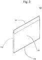
- a blade that incises the containers 40 as shown in Fig. 3 is used as the perforation/incision part 13 (indicated as the "blade 13" when the perforation/incision part 13 is specified as the blade).
- the blade 13 shown in Fig. 3 is of a double-edge structure, such that both the lateral surface 132 and the lateral surface 133 incline in the vicinity of the edge 131 and intersect with each other at the edge 131, although the blade is not limited thereto.
- a blade of a single-edge structure such that one of the two lateral surfaces 132 and 133 inclines, the other remain flat, and such surfaces intersect with each other at the edge 131 may be employed.
- the perforation/incision part 13 is not limited to the blade.
- An example of the perforation/incision part 13 other than the blade is a needle that perforates the containers 40.
- a plurality of containers 40 are incised at a single perforation/incision part 13, the construction is not limited thereto, and a plurality of perforation/incision parts 13 may be provided in accordance with the relevant containers.
- Materials constituting the perforation/incision part 13 are not particularly limited, provided that such materials can provide sufficient strength to perforate or incise the containers 40. Examples thereof include metals, such as steels and aluminum, ceramics, and resin.
- the perforation/incision part 13 is provided inside the internal space 11 of the housing 10. According to the present embodiment, the perforation/incision part 13 is provided on the bottom wall 101 facing the holes 12 inside the internal space 11 of the housing 10, although the perforation/incision part 13 is not limited thereto.
- a fixing part 17 provided upright from the bottom wall 101 toward the hole-formed part 14 of the housing is provided inside the internal space 11, and a perforation/incision part 13 is fixed to the housing 10 through the fixing part 17.
- the fixing part 17 is arranged on the same line with the support-mounting part 16 in the bottom wall 101.
- the upper surface 17a of the fixing part 17 is located in a position lower than the upper surface 16a of the support-mounting part 16.
- the support-mounting part 16 is connected to the fixing part 17 with the connector 18 provided upright from the bottom wall 101 in the internal space 11.
- the upper surface 16a of the support-mounting part 16 is connected to the upper surface 17a of the fixing part 17 through the upper surface 18a of the connector 18 inclined from the upper surface 16a of the support-mounting part 16 toward the upper surface 17a of the fixing part 17.
- third positioning protrusive parts 17b are provided on both sides of the fixing part 17 that fixes the perforation/incision part 13 in the short-width direction of the upper surface 17a.
- the perforation/incision part 13 fixed by the fixing part 17 and the liquid receiver 31 of the chromatography support 30 provided between the holes 12 and 12 migrate toward the fixing part 17.
- migration of the liquid receiver 31 is restricted to the direction of the migration of the lid 20.
- the holes 12 formed in the hole-formed part 14 of the housing 10 are through holes that allow communication between the internal space 11 and the outside of the housing 10.
- the configuration of the holes 12 is not particularly limited, provided that the containers 40 can be inserted thereinto and supported thereby in a through-hole direction, and the containers 40 can be guided to move toward the perforation/incision part 13 as the lid 20 migrates.
- the container 40 a container that can accommodate liquid L used for chromatography, that can be inserted into and supported by the hole 12 of the housing 10, and that can be perforated or incised by the perforation/incision part 13 can be used.
- the container 40 is typically a resin container.
- a tubular container that extends in one direction with one end being closed and the other end having an opening is preferable.
- the embodiment shown in the figure specifically, employs a container that has an opening 41a at the outer end 41 positioned outside of the housing 10 and that is closed at the inner end 42 positioned inside of the housing 10 when the containers are inserted into the holes 12.
- An example of such container 40 is a microtube used for nucleic acid amplification or biochemical testing.
- the hole-formed part 14 of the housing comprises, at a position surrounding a relevant hole 12, an elastic member 190 that urges the container 40, which is inserted into and supported by the hole 12, against the axis along the through-hole direction of the hole 12 and retains the position of the container 40 in the hole 12 .
- the elastic member 190 is composed of a pair of elastic supporting pieces 191 and 192 protruded from a pair of positions facing each other in the vicinity of the hole 12 on the inner surface 14b facing the internal space 11 of the hole-formed part 14 of the housing toward the internal space 11.
- the pair of elastic supporting pieces 191 and 192 are positioned in a manner such that a surface 191a of an elastic supporting piece 191 faces a surface 192a of the other elastic supporting piece 192.
- the surface 191a of an elastic supporting piece 191 and the surface 192a of the other elastic supporting piece 192 are formed in a manner such that the distance therebetween becomes smaller as the distance along the direction X from the inner surface 14b of the hole-formed part 14 of the housing becomes larger.
- the pair of elastic supporting pieces 191 and 192 flank the container 40 inserted into the hole 12 and urge the container against the axis along the through-hole direction of the hole 12 to retain the position.
- the pair of elastic supporting pieces 191 and 192 are capable of elastic deformation. As the container 40 is pushed toward the perforation/incision part 13, the elastic supporting pieces are pushed to open in accordance with the configuration of the container 40.
- the position of the container 40 can be stably maintained even with the use of the container 40 configured to have an increasing width from the inner end 42 toward the outer end 41.
- the elastic supporting pieces 191 and 192 are capable of elastic deformation, a container 40 with a different width can be supported stably.
- the positions of the containers 40 inserted into the holes 12 can be maintained with the aid of the elastic member 190 composed of the pair of elastic supporting pieces 191 and 192.
- the position of the container 40 with respect to the perforation/incision part 13 can be stabilized, and the amount of liquid L leaking from the container 40 can be stabilized.
- the containers 40 are inserted into and supported by the holes 12 of the housing 10, and the lid 20 is mounted on the lid-mounting part 15 surrounding the hole-formed part 14 of the housing 10.
- the housing-side screw-engagement part 51 on the outer peripheral surface 15a of the lid-mounting part 15 of the housing 10 is allowed to partially engage with the lid-side screw-engagement part 52 on the inner peripheral surface 22a of the peripheral wall part 22 of the lid 20.
- the hole-formed part 14 of the housing 10 and the outer regions 40a of the container 40 are covered by the lid 20.
- the containers 40 are not perforated or incised at the perforation/incision part 13.
- the container 40 When the lid 20 is positioned in the first position, specifically, the container 40 is located between the main lid part 21 of the lid 20 and the perforation/incision part 13 facing each other.
- the inner ends 42 of the containers 40 may not be in contact with the edge 131 of the perforation/incision part 13. Alternatively, they may be in contact with each other, but the containers are not perforated or incised.
- the outer portions 40a of the containers 40 and the hole-formed part 14 of the housing are covered by the lid 20 before liquids L are allowed to leak from the containers 40.
- a space S is formed between the hole-formed part 14 of the housing 10 and the lid 20.
- a space S is communicated with the internal space 11 of the housing 10 through the holes 12.
- the entire space S is a closed space within the test device 1, it is not necessarily airtight.
- the height of the space S is the distance D described above, and the distance D is the first distance described above.
- the entire containers 40 are enclosed in a closed space. Thus, dispersion of liquids L from the test environment can be effectively suppressed.
- the hole-formed part of the housing is covered by the lid, and the lid is positioned in the first position with respect to the housing.
- a part of the lid facing the hole-formed part of the housing may or may not abut against the outer portion protruded from the one or more holes of the container toward the lid.
- the part of the lid facing the hole-formed part of the housing and the outer portion protruded from the one or more holes of the container toward the lid may begin to abut against each other while the lid migrates from the first position to the second position toward the housing.
- a main lid part 21 of the lid 20 which faces the hole-formed part 14 of the housing, abuts against the outer end 41 of the container 40 when the lid 20 is in the first position, although the present invention is not limited to such embodiment.
- a given main lid part 21 of the lid 20 may be located separately from the outer end 41 of the container 40, and the main lid part 21 may begin to abut against the outer end 41 of the container 40 while the lid 20 migrates from the first position to the second position.
- the liquid receiver 31 of the chromatography support 30 when the lid 20 is positioned in the first position, the liquid receiver 31 of the chromatography support 30 is located between the inner end 42 of the container 40 and the edge 131 of the perforation/incision part 13.
- the liquid receiver 31 is not necessarily positioned in this position, but it may be positioned in a manner such that it can come into contact with the leaked liquid L when liquid L leaks into the internal space 11.
- Fig. 5B schematically shows the condition during the process of migration.
- the main lid part 21 of the lid 20 abuts against the outer end 41 of the container 40, the container 40 is pushed toward the perforation/incision part 13, the container 40 is perforated or incised at the perforation/incision part 13 (incised according to an embodiment shown in the figure), and liquid L then leaks into the internal space 11.
- the lid 20 migrates while covering the hole-formed part 14 of the housing 10. In the internal space 11, accordingly, liquid L leaked from the container 40 can be suppressed to disperse outside the test device 1.
- the main lid part 21 of the lid 20 abuts against the outer end 41 of the container 40.
- an opening 41a of a microtube would not open when a microtube having an opening 41a at the outer end 41 is used as the container 40. This can suppress the opening 41a of the microtube to open, even when the container 40 is pushed against the perforation/incision part 13 and the pressure inside the container is increased.
- the guide 50 is composed of the housing-side screw-engagement part 51 and the lid-side screw-engagement part 52, the lid 20 mounted on the housing 10 in the first position revolves around the direction X, and the main lid part 21 of the lid 20 migrates along the direction X toward the hole-formed part 14 of the housing 10.
- a torsion is applied in a direction approximately vertical to the direction X, and the container 40 is pushed along the direction X toward the perforation/incision part 13.
- Fig. 5B schematically shows that the container 40 is pushed into the perforation/incision part 13 with some inclination from the direction X as the lid 20 revolves. This opens the leakage port 43 formed via perforation or incision of the container, liquid L is effectively leaked, and chromatography conditions can be thus stabilized.
- the containers 40 are each pushed into the perforation/incision part 13 while the positions thereof in the holes 12 are maintained by the pair of elastic supporting pieces 191 and 192.
- the position thereof with respect to the perforation/incision part 13 can be kept stable, the amount of liquid L leaked from the container can be kept constant, and chromatography conditions can be thus stabilized.
- Liquids L leaks from the containers 40 through the leakage port 43 to regions on the fixing part 17 of the perforation/incision part 13 and in the vicinity of the fixing part 17.
- a reservoir space for storing liquid L may be separately provided in the internal space 11.
- the liquid receiver 31 of the chromatography support 30 is pushed into the perforation/incision part 13 by the inner end 42 of the container 40, the liquid receiver 31 is perforated or incised together with the container 40 at the edge 131 of the perforation/incision part 13, and the liquid receiver 31 approaches the fixing part 17.
- the present invention is not limited to the present embodiment, and the liquid receiver 31 of the chromatography support 30 may be positioned in any position, provided that it can come into contact with liquid L leaked in the internal space 11.
- Fig. 4B and Fig. 5C each schematically show the conditions in which the lid 20 is further allowed to migrate to the second position toward the housing 10.
- the liquid receiver 31 of the chromatography support 30 In the second position, a large amount of liquid L leaks, the liquid receiver 31 of the chromatography support 30 is sufficiently soaked in the leaked liquid L, and development thereof on the chromatography support 30 proceeds.
- the third positioning protrusive parts 17b are provided in positions flanking the liquid receiver 31 of the chromatography support 30 in a width direction.
- movement of the liquid receiver 31 is limited to one direction along the direction X in which the lid 20 moves from the first position to the second position.
- the liquid receiver 31 can be soaked in liquid L with certainty.
- the present embodiment as shown in Fig.
- the liquid receiver 31 of the chromatography support 30 begins to be soaked in liquid L while the lid 20 migrates from the first position to the second position, although the constitution is not limited thereto.
- the liquid receiver 31 may be constituted in a manner such that the liquid receiver 31 is first soaked in liquid L when the housing 20 is positioned in the second position.
- the distance D between the outer surface 14a of the hole-formed part 14 of the housing and the inner surface 21a of the main lid part 21 of the lid 20 facing the outer surface 14a is the second distance, which is smaller than the first distance.
- the second distance is larger than 0, and the space S remains between the outer surface 14a of the hole-formed part 14 of the housing and the inner surface 21a of the main lid part 21 of the lid 20.
- the present invention is not limited to such embodiment, the second distance may be zero, and the space S may not be present.
- the lid 20 covers the hole-formed part 14 of the housing 10.
- liquid L leaked into the internal space 11 can be prevented from dispersing to the outside of the test device 1.
- the test device 1 is constructed in a manner such that the lid-mounting part 15 surrounds the hole-formed part 14 of the housing, as described above.
- the housing 10 is constituted in a manner such that the profile 400 of the outer portion 40a of the container 40 is enclosed in the inner periphery 150 of the lid-mounting part 15, when the container 40 inserted into and supported by the hole 12 is viewed from the outside of the housing 10 in the through-hole direction of the hole 12. Because of this constitution, the lid 20 is easily mounted while the containers 40 are inserted into the holes 12 of the housing 10, and migration of the lid 20 from the first position to the second position is less likely to be blocked by the outer portion 40a of the container 40.
- the housing 10 is constituted in a manner such that the profiles 400 of the outer portions 40a of the containers 40 are enclosed in the inner periphery 150 of the lid-mounting part 15 while the containers 40 remain inserted into and supported by the holes 12, regardless of the direction of the containers 40 in the holes 12.
- the lid 20 can be mounted on the lid-mounting part 15 without causing interference between the lid 20 and the outer portion 40a of the container 40 when the container 40 is inserted into the hole 12 of the housing 10, regardless of the direction of the container 40 in the hole 12. This enables a user to operate the test device according to the present embodiment, regardless of the direction of the container.
- the container 40 comprising an opening 41a at the outer end 41 as shown in the figure generally comprises, in the periphery of the opening 41a, a hinge 401 and a pinch 402 that would protrude outwardly from the profile 400 in a plane view of the outer end 41.
- the lid 20 can be mounted on the lid-mounting part 15 while the container 40 comprising an opening 41a at the outer end 41 remains inserted into the hole 12, regardless of the direction.
- the housing 10 is not necessarily constituted in a manner such that the profile 400 of the outer portion 40a of the container 40 is enclosed in the inner periphery 150 of the lid-mounting part 15 while the container 40 remains inserted into and supported by the hole 12, regardless of the direction of the container 40 in the hole 12.
- effects similar to those achieved by the present embodiment can be achieved by constituting the housing 10 as described below.
- the test device 1 also comprises undulated surfaces 102d formed on at least a part of the outer surface 102a of the side wall 102, which is the lateral surface of the housing 10.
- the undulated surfaces 102d are formed of continuous plurality of grooves 102e in the direction in which the bottom wall 101 and the upper wall 103 of the housing 10 face each other. Because the undulated surfaces 102d are provided on the outer surfaces 102a of the side wall 102, slip caused when a user operates the test device with fingers can be prevented.
- the undulated surfaces 102d can be engaged with each other.
- An undulated surface is an example of a concave-convex surface.
- concave-convex surfaces with different configurations may be provided instead of the undulated surfaces 102d.
- a concave-convex surface is formed of a plurality of continuous grooves extending in one direction, and a flat surface may be formed between grooves adjacent to each other.
- a configuration of a cross section of a plane vertical to the extending direction is not particularly limited.
- An example of a surface having a cross section with a curved configuration is an undulated surface shown in the figure.
- a configuration of the cross section may be a rectangle or U-shape.
- the upper surface 17a of the fixing part 17 is flat, and the blade 13 is provided in a manner such that the lateral surfaces 132 and 133 are positioned to be vertical to the upper surface 17a of the fixing part 17.
- the structure in the vicinity of the blade 13 can be adequately regulated. Specific variation examples are as described below.
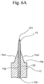
- Fig. 6A , Fig. 6B , and Fig. 6D each schematically show a cross section taken at a plane vertical to the direction in which the edge 131 of the blade 3 extends in the vicinity of the fixing part 17 and the blade 13 of each variation example.
- a variation example shown in Fig. 6A comprises the sloped portion 17a1 that is inclined to approach the edge 131, as the upper surface 17a of the fixing part 17 approaches the lateral surfaces 132 and 133 in the vicinity of the blade 13.
- the leakage port 43 is incised not only by the blade 13 but also by the sloped portion 17a1 of the upper surface 17a of the fixing part 17.
- a larger leakage port 43 can be formed.
- a variation example shown in Fig. 6B comprises the sloped portion 17a2 that is inclined to approach the edge 131, as the upper surface 17a of the fixing part 17 approaches the lateral surfaces 132 and 133 in the vicinity of the blade 13.
- the sloped portion 17a2 has a concave-convex structure comprising a plurality of concave grooves 171 extending along the direction from the fixing part 17 to the edge 131 of the blade 13 arranged in parallel at intervals.
- the container 40 is pushed from the edge 131 of the blade 13 toward the base end 134 of the blade 13, the leakage port 43 is incised not only by the blade 13 but also by the sloped portion 17a2 on the upper surface 17a of the fixing part 17, and liquid L efficiently leaks into the internal space 11 through a plurality of the concave grooves 171.
- the leakage port 43 is incised not only by the blade 13 but also by the sloped portion 17a2 on the upper surface 17a of the fixing part 17, and liquid L efficiently leaks into the internal space 11 through a plurality of the concave grooves 171.
- liquid L efficiently leaks into the internal space 11 through a plurality of the concave grooves 171.
- a variation example shown in Fig. 6D comprises the sloped portion 17a3 that is inclined to approach the edge 131, as the upper surface 17a of the fixing part 17 approaches the lateral surfaces 132 and 133 in the vicinity of the blade 13.
- a slope of the sloped portion 17a3 continuously becomes shallow as it approaches the lateral surfaces 132 and 133.
- the container 40 is pushed from the edge 131 of the blade 13 toward the base end 134 of the blade 13, and the leakage port 43 is incised not only by the blade 13 but also by the sloped portion 17a3 on the upper surface 17a of the fixing part 17.
- a larger leakage port 43 can be formed.
- the test device 1 according to the first embodiment comprises:
- This feature is referred to as the "other feature 1.”
- the supporting part may be a part of the housing in which a structure supporting two or more containers accommodating liquids for chromatography is formed.
- a specific example of the supporting part is the hole-formed part 14 of the housing provided with holes 12 through which two or more containers 40 are supported.
- the test device 1 having the other feature 1 is capable of perforation or incision of two or more containers 40 at a single perforation/incision part 13 to leak liquids L from the containers 40 into the internal space 11.
- the test device 1 having the other feature 1 is simply structured, and such test device can be produced at a lower cost. In such a case, the test device 1 is not necessarily equipped with the lid 20.
- the perforation/incision part is the blade 13
- the supporting part is the hole-formed part 14 provided with two or more holes 12 through which two or more containers 40 are supported.
- two or more containers 40 are provided to face each other at different positions on the edge 131 of the single blade 13.
- the two or more holes 12 are constructed in a manner such that the containers 40 are guided by the blade 13 from the position facing the edge 131 of the blade 13 to the site to be incised by the blade 13 when the containers 40 inserted into the two or more holes 12 are pushed toward the blade 13.
- test device 1 having the other feature 1 more preferably comprises some or all the features described with reference to the test device 1 according to the first embodiment described herein.
- the test device 1 according to the first embodiment comprises:
- This feature is referred to as the "other feature 2.”
- the chromatography support 30 (hereafter, it is occasionally referred to as the "support 30") is positioned to face the upper wall 103 of the housing 10 in a position close to the upper wall 103, and a part 103c of the upper wall 103 is visible light permeable. Accordingly, the support 30 is sufficiently visible at the time of chromatographic development.
- the part 103c of the upper wall 103 of the housing 10 is not particularly limited, provided that it is visible light permeable to the extent that the support 30 in the housing 10 is visually observable from the outside of the housing 10 through the part 103c of the upper wall 103 under application of light including visible light, such as sunlight.
- a specific configuration of the support-mounting part 16 is a protrusive part rising upright from the bottom wall 101 toward the upper wall 103 in the internal space 11, which is provided with an upper surface 16a on which at least a part of the support 30 can be provided.
- the whole of the support 30 is not necessary provided on the support-mounting part 16, and it may be provided in at least a part thereof. At least a part comprising the detection part 32 of the support 30 is preferably provided on the support-mounting part 16, so that the detection part 32 is visible through the upper wall 103.
- the housing 10 comprises the side wall 102.
- the test device 1 is disposed on a horizontal surface to adjust the bottom wall 101 of the housing 10 to be on the lower side, accordingly, the test device can be easily operated while touching the side wall 102 of the housing 10 with fingers; that is, the test device is easy to handle.
- a height of the side wall 102 can be adequately determined, it is preferably 4 mm or more, and more preferably 6 mm to 20 mm.
- the support 30 is provided in a position closer to the upper wall 103 even if the housing 10 has a thickness in accordance with the height of the side wall 102. Thus, visual observation is easily carried out through the upper wall 103.
- test device 1 having the other feature 2 When the test device 1 having the other feature 2 is disposed on a horizontal surface to adjust the bottom wall 101 of the housing 10 to be on the lower side, a portion disposed on the support-mounting part 16 of the support 30 is positioned in a position higher than the bottom wall 101.
- the portion disposed on the support-mounting part 16 of support 30 is less likely to come into direct contact with liquid L leaked from the containers 40 at the perforation/incision part 13, and chromatographic development can be easily performed with high accuracy.
- the test device 1 having the other feature 2 does not necessarily comprise the lid 20.
- test device 1 having the other feature 2 more preferably comprises some or all the features described with reference to the test device 1 according to the first embodiment described herein.
- the distance D2 between a part of the support 30 provided on the support-mounting part 16 and the upper wall 103 is preferably 10 mm or less (see Fig. 4A , Fig. 4B , and Fig. 14 ).
- the term "the distance D2 between a part of the support 30 provided on the support-mounting part 16 and the upper wall 103" used herein refers to the shortest distance among various distances between the part of the support 30 provided on the support-mounting part 16 and the upper wall 103.
- the distance D2 between the entire part of the support 30 provided on the support-mounting part 16 and the upper wall 103 is preferably 10 mm or less.
- the part of the support 30 provided on the support-mounting part 16 is in a position sufficiently close to the upper wall 103. Under visible light, accordingly, visual observation can be easily performed from the outside of the housing 10 through the upper wall 103.
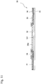
- a surface 30a of the support 30 facing the upper wall 103 is preferably covered by the visible light permeable protective film 36, as shown in Fig. 11 and Fig. 12 .
- Fig. 11 shows an embodiment of the chromatography support 30 shown in Fig. 9 comprising the surface 30a facing the upper wall 103 covered by the protective film 36.
- Fig. 12 shows an embodiment of the chromatography support 30 shown in Fig. 10 comprising the surface 30a facing the upper wall 103 covered by the protective film 36.
- Use of the support 30 comprising the surface 30a covered by the visible light permeable protective film 36 is preferable since chromatographic development is less likely to be influenced by the contact between the surface 30a of the support 30 and the upper wall 103.
- the visible light permeable protective film 36 can be a visible light permeable film through which liquid L does not substantially penetrate.
- the protective film 36 is not particularly limited, provided that it is visible light permeable to the extent that the lower surface of the protective film 36 of the support 30 is visually observable with the application of light including visible light, such as sunlight.
- the part 103c of the upper wall 103 of the housing 10 facing the support 30 has a thickness of 20 ⁇ m to 10 mm and total luminous transmittance of 70% or more.
- the total luminous transmittance represents the ratio of the transmitted luminous flux to the parallel incident luminous flux of the test piece, which is standardized under JIS 7375:2008. In such a case, visual observation of the support 30 can be performed particularly clearly from the outside of the housing 10 through the part 103c of the upper wall 103.
- an area accounting for 5% or more of the total area of the housing 10 is preferably a visible light permeable part 103c of the upper wall 103 facing the support.
- Fig. 13 shows a plane view of the housing 10.
- the visible light permeable part 103c of the upper wall 103 facing the support is preferably 5% or more relative to the total area of the housing 10 when the housing 10 is viewed horizontally, as shown in the plane view shown in Fig. 13 .
- This embodiment is preferable since visibility of the support 30 from the outside of the housing 10 through the part 103c of the upper wall 103 is particularly high.
- the test device 1 having the other feature 2 preferably, at least either one of the outer surface (the upper surface) 103a and the inner surface (the lower surface) 103b of the upper wall 103 of the housing 10 is provided with an antireflection member 140.
- the term "the outer surface” of the upper wall refers to a surface of the upper wall outside the housing, and the term “inner surface” of the upper wall refers to a surface of the upper wall inside the housing.
- Fig. 14 shows a partial structure associated with the housing 10 of the test device 1 according to this embodiment in which the antireflection member 140 is provided on an outer surface (an upper surface) 103a of the upper wall 103 of the housing 10.
- the total luminous transmittance of the antireflection member 140 is preferably 2% or less, and more preferably 1% or less.
- the total luminous transmittance represents the ratio of the transmitted luminous flux to the parallel incident luminous flux of the test piece, which is standardized under JIS 7375:2008.
- the test device 1 having the other feature 2 preferably comprises a visible light permeable protrusive part 103d extending along the support 30 toward the outside of the housing 10 in a position 103c1 outside of the housing 10 where the part 103c of the upper wall 103 of the housing 10 faces the support 30.
- Fig. 15A and Fig. 15B each show the upper housing member 10A constituting the first example of the housing 10 of the test device 1 according to the present embodiment.
- Fig. 16A and Fig. 16B each show the upper housing member 10A constituting the second example of the housing 10 of the test device 1 according to the present embodiment.
- the outer surface 103d1 of the protrusive part 103d is a part of a cylindric surface around the axis along the direction of the protrusive part 103d extending along the support 30.
- the second example of the housing 10 as shown in Fig. 16A and Fig.
- the outer surface 103d1 of the protrusive part 103d is a part of a polygonal tube surface around the axis along the direction of the protrusive part 103d extending along the support 30.
- the protrusive part 103d of the upper wall 103 of the housing 10 is not particularly limited, provided that it is visible light permeable to the extent that the support 30 in the housing 10 is visually observable from the outside of the housing 10 through the protrusive part 103d and the part 103c of the upper wall 103 under application of light including visible light, such as sunlight.
- the test device 1 according to the first embodiment also comprises:
- This feature is referred to as the "other feature 3.”
- the supporting part may be a part of the housing in which a structure supporting the container accommodating a liquid for chromatography is formed.
- a specific example of the supporting part is the hole-formed part 14 of the housing provided with holes 12 through which the containers 40 are inserted and supported.
- Examples of the container guide include holes 12 formed in the hole-formed part 14 of the housing. Each of the holes 12 functions as a guide hole that guides the container 40, which is inserted into and supported by the hole, from position A to position B.
- a part of the support 30 positioned between the supporting part and the perforation/incision part 13 is the liquid receiver 31 of the support 30 according to an embodiment shown in the figure.
- the part of the support 30 positioned between the supporting part and the perforation/incision part 13 is not limited thereto, and it may be a part other than the detection part 32 of the support 30 (e.g., an upstream end of development on the support 30).
- Fig. 4A and Fig. 5A each schematically show a cross sectional view of the test device 1 in which the container 40 is located in position A.
- the container 40 located in position A is inserted into and supported by a hole (i.e., a container guide) 12 formed in the hole-formed part (the supporting part) 14 of the housing, it faces the edge 131 of the perforation/incision part 13 at the inner end 42, and a liquid receiver 31, which is a part of the support 30, is positioned between the inner end 42 of the container 40 and the edge 131 of the perforation/incision part 13.
- Fig. 4B and Fig. 5C each schematically show a cross sectional view of the test device 1 in which the container 40 is located in position B.
- the container 40 located in position B is perforated or incised together with the liquid receiver 31, which is a part of the support 30, at the perforation/incision part 13.
- the outer portion 40a of the container 40 in position A is located outside the housing 10.
- the container 40 is guided by the hole (i.e., the container guide) 12 to position B.
- the inner end 42 of the container 40 and the liquid receiver 31 of the support 30 are pushed against the edge 131 of the perforation/incision part 13 and then perforated or incised.
- liquid L leaked from the container 40 is able to come into contact with the liquid receiver 31 of the support 30 and penetrate into the liquid receiver 31 immediately with certainty.
- the test device 1 having the other feature 3 is preferable since it is capable of efficiently bringing liquid L leaked from the container 40 into contact with the support 30.
- the test device 1 having the other feature 3 is not necessarily equipped with the lid 20 shown in Fig. 1A to Fig. 5C .
- the test device 1 that does not comprise the lid 20 but comprises the housing 10 may be used, and such test device 1 may be operated in a manner such that a user pushes the outer portion 40a of the container 40 supported by the hole 12 of the hole-formed part 14 of the housing with fingers.
- the second embodiment ( Fig. 7 ) and the third embodiment ( Fig. 8 ) of the present invention are described below.
- the constitutions and the functions in common with those according to the first embodiment are numbered in the same manner and descriptions thereof are omitted.
- the chromatography support 30 is provided in the internal space 11 in a manner such that the direction X in which the hole-formed part 14 of the housing 10 faces the lid 20 and the container 40 is pushed toward the perforation/incision part 13 becomes orthogonal to the direction Y in which the portion comprising the detection part 32 of the chromatography support 30 provided in the internal space 11 of the housing 10 extends and liquid L develops.
- the test device 1 according to the first embodiment comprising the chromatography support 30 provided in the internal space 11 is disposed on a horizontal surface, so that the container 40 is pushed downward in a vertical direction and liquid L is developed in a horizontal direction in the detection part 32 on the chromatography support 30.
- the chromatography support 30 may be provided in any direction in the internal space 11 of the housing 10.
- the chromatography support 30 is provided in the internal space 11 in a manner such that the direction X in which the hole-formed part 14 of the housing 10 faces the lid 20 and the container 40 is pushed toward the perforation/incision part 13 becomes approximately the same as the direction Y in which an area of the chromatography support 30 comprising the detection part 32 provided in the internal space 11 of the housing 10 extends and liquid L develops.
- the chromatography support 30 is provided in the internal space 11 in a manner such that the direction X in which the hole-formed part 14 of the housing 10 faces the lid 20 and the container 40 is pushed toward the perforation/incision part 13 becomes approximately the same as the direction Y in which an area of the chromatography support 30 comprising the detection part 32 provided in the internal space 11 of the housing 10 extends and liquid L develops.
- the chromatography support 30 is provided in the internal space 11 in a manner such that it is bent between the liquid receiver 31 and the detection part 32 and an area of the chromatography support 30 comprising the liquid receiver 31 is positioned between the hole-formed part 14 of the housing and the perforation/incision part 13.
- a test device is constructed in a manner such that a plurality of chromatography supports are provided in a single housing and a liquid leaked from the container comes into contact with a relevant chromatography support.
Landscapes
- Chemical & Material Sciences (AREA)
- Health & Medical Sciences (AREA)
- Life Sciences & Earth Sciences (AREA)
- General Health & Medical Sciences (AREA)
- Analytical Chemistry (AREA)
- Biochemistry (AREA)
- Engineering & Computer Science (AREA)
- Organic Chemistry (AREA)
- Immunology (AREA)
- Physics & Mathematics (AREA)
- Bioinformatics & Cheminformatics (AREA)
- Zoology (AREA)
- Wood Science & Technology (AREA)
- Pathology (AREA)
- General Physics & Mathematics (AREA)
- Biotechnology (AREA)
- Chemical Kinetics & Catalysis (AREA)
- Hematology (AREA)
- Clinical Laboratory Science (AREA)
- Microbiology (AREA)
- Genetics & Genomics (AREA)
- General Engineering & Computer Science (AREA)
- Proteomics, Peptides & Aminoacids (AREA)
- Sustainable Development (AREA)
- Biomedical Technology (AREA)
- Medicinal Chemistry (AREA)
- Biophysics (AREA)
- Molecular Biology (AREA)
- Dispersion Chemistry (AREA)
- Sampling And Sample Adjustment (AREA)
- Apparatus Associated With Microorganisms And Enzymes (AREA)
- Treatment Of Liquids With Adsorbents In General (AREA)
Abstract
Description
- The present invention relates to a test device used for chromatography.
- Nucleic acid chromatography is carried out on a chromatography support comprising a nucleic acid immobilized thereon to develop, capture, and detect a detection target comprising a nucleic acid tag hybridizing to the nucleic acid immobilized on the support. Nucleic acids comprising different nucleotide sequences are immobilized on a chromatography support at different positions, and each of a plurality of detection targets is tagged with a nucleic acid tag specific to the nucleic acid, so that a plurality of detection targets contained in a single specimen can be detected on a single support. In addition to nucleic acid chromatography, techniques of chromatography comprising capturing the detection targets on a chromatography support with the use of an antigen-antibody combination or a ligand-receptor combination capable of forming a specific bond are extensively used in the field of, for example, molecular biological testing or genetic testing for medical or food testing.
- The chromatography techniques as described above involve the use of various types of liquids, such as a sample liquid containing detection targets or developing liquids. When such liquids are removed from a container with the use of an instrument, such as a pipette, and applied to a chromatography support, the liquid may disperse in the testing environment and contaminate the environment, which may lead to a false-positive result. By opening the container in the test environment, a liquid in the container may be contaminated.
- An apparatus that breaks a part of a container to allow a liquid to leak therefrom and brings the leaked liquid into contact with a chromatography support while maintaining a liquid, such as a sample liquid or developing liquid, used for chromatography inside the container without the use of an instrument, such as a pipette, has been developed.
- For example, a device for detection of analytes in affinity bioassays disclosed in
Patent Document 1 comprises at least one transparent wall, at least one test recess adapted to receive at least one test strip and arranged in a manner such that said test strip is visible through the transparent wall, at least one cavity adapted to receive a container accommodating a fluid sample, said cavity being in fluid communication with said at least one test recess, and piercing means arranged in correspondence with said at least one cavity, in a manner such that, upon insertion of a container in the cavity, the container is pierced and at least an area of the sample is released from the container and reaches the test recess. - Also, a totally-enclosed device for quick detection of a target nucleic acid amplification product disclosed in Patent Document 2 comprises an inner core and an outer casing, wherein the inner core comprises a fixing case part and a base part, the fixing case part being provided with two holes respectively for housing washing buffer vacuoles and a PCR tube containing an amplification product, the base part comprising a washing buffer container element having a vacuole puncture needle, an amplification product container element having a blade, a sealing diaphragm, a piece of glass fiber paper, and a test strip sealing part having a transparent window; and the outer casing comprises a handle cover, a fixing case pressing part, a washing buffer vacuole extruding part, and a transparent window.
-
- Patent Document 1:
JP 2015-51 2250 A - Patent Document 2:
JP 2010-500009 A -
Patent Document 1 discloses that a container accommodating a liquid containing a sample is pierced only when the container is inside the device and the container is then released on a test strip. Thus, sample contamination can be avoided. - In
Patent Document 1, however, the problem of contamination is not sufficiently dissolved. In the device according toPatent Document 1, the opening of the recess into which the container is to be inserted is open to the outside. When the container is inserted into and pushed down in the recess and the liquid is released by piercing the container, accordingly, a liquid may leak from the space between the container and the recess. When the container is pierced by a piercing means, the pressure inside the container may be elevated upon invasion of the piercing means into the bottom of the container, and an opening at the top of the container may open. - Patent Document 2 also discloses that use of the device disclosed in Patent Document 2 enables testing of a PCR amplified product in a totally enclosed state and prevention of an experimental laboratory from contamination.
- However, the structure of the device according to Patent Document 2 is complicated. This complicates the operation and increases a risk of errors. Thus, such device is not preferable. In addition, the problem of contamination is not sufficiently dissolved with the use of the device according to Patent Document 2. In the device according to Patent Document 2, a fixing case part is composed of two members comprising a hole corresponding to a PCR tube when they are superposed to each other, and the two members laterally sandwich the PCR tube in positions in the vicinity of the opening at the top of the PCR tube to fix the PCR tube. When sandwiching a PCR tube with the two members, it is necessary to arrange the PCR tube in adequate directions. When the PCR tube is not adequately arranged, the opening of the PCR tube may be opened, disadvantageously.
- An aspect of the present invention provides a test device that can reduce contamination when a liquid comes into contact with a chromatography support.
- An aspect of the present invention provides a test device that is provided with a simple mechanism for allowing a liquid used for chromatography to efficiently leak from the container accommodating the liquid.
- An aspect of the present invention provides a test device that is provided with a chromatography support accommodated in a housing and is easily observed from the outside of the housing.
- An aspect of the present invention provides a test device comprising a chromatography support accommodated in a housing that can allow a liquid used for chromatography to leak from the container accommodating the liquid and efficiently bring the liquid into contact with the support.
- The test device according to an aspect of the present invention comprises:
- a housing enclosing an internal space where chromatography involving the use of a chromatography support is carried out, the housing having at least one hole through which the internal space is communicated with the outside and at least one container accommodating a liquid used for chromatography is inserted and supported, and the housing comprising a perforation/incision part provided in the internal space that perforates or incises the container to leak the liquid from the container into the internal space; and
- a lid mounted on the housing that covers a hole-formed part of the housing where the at least one hole is formed,
- wherein at least either one of the housing and the lid comprises a guide that guides the lid to the housing in a manner such that, while the lid covers the hole-formed part of the housing, the lid can migrate from a first position where the lid covers the hole-formed part of the housing while keeping a space therebetween and where the distance between the hole-formed part of the housing and a part of the lid facing the hole-formed part of the housing designated as a first distance to a second position where the lid covers the hole-formed part of the housing and where the distance between the hole-formed part of the housing and a part of the lid facing the hole-formed part of the housing is a second distance smaller than the first distance,
- when the lid is allowed to migrate from the first position to the second position while supporting the container through the at least one hole of the housing and covering the hole-formed part of the housing with the lid,
- the first position is a position where the lid covers the hole-formed part of the housing and an outer portion of the container protruded toward the lid through the at least one hole and the container is not perforated or incised at the perforation/incision part, and
- while the lid is allowed to migrate from the first position to the second position, the housing and the lid are guided by the guide in a manner such that the part of the lid abuts against an end of the outer portion of the container, the container is pushed toward the perforation/incision part, and the perforation/incision part perforates or incises the container to leak the liquid into the internal space.
- With the use of the test device according to the aspect of the present invention, for example, a risk of contamination occurring when a liquid comes into contact with the chromatography support is reduced by the action described below.
- At the outset, the container accommodating a liquid is inserted into and supported by the at least one hole of the housing and the lid is positioned in the first position with respect to the housing. In such a state, the lid covers the hole-formed part of the housing and the outer portion of the container protruding from the at least one hole toward the lid. However, the perforation/incision part does not perforate or incise the container in that state. Specifically, the outer portion of the container and the hole-formed part of the housing are covered by the lids before liquid leaks from the container.
- Subsequently, during the process of migration of the lid from the first position to the second position, the part of the lid abuts against the end of the outer portion of the container. Thus, the container is pushed toward the perforation/incision part, the container is perforated or incised at the perforation/incision part, and the liquid leaks into the internal space. During the process, the lid migrates while covering the hole-formed part of the housing. Thus, dispersion of a liquid leaked from the container to the outside of the test device can be suppressed. During this process, in addition, the part of the lid abuts against the end of the outer portion of the container. When a microtube comprising an opening at the end is used as the container, the opening of the microtube would not be opened unintentionally.
- According to a preferable embodiment of the test device according to the aspect of the present invention,
the housing comprises a lid-mounting part formed to surround the hole-formed part of the housing on which the lid is to be mounted, and
when the housing with the container inserted into and supported by the at least one hole of the housing is viewed from the outside of the housing in the through-hole direction, the housing is constructed in a manner such that a profile of the outer portion of the container is enclosed within the inner periphery of the lid-mounting part. - According to the embodiment of the test device according to the aspect of the present invention, the lid can be easily mounted while the container is inserted into and supported by the at least one hole of the housing, and migration of the lid from the first position to the second position is less likely to be blocked by the outer portion of the container.
- According to another preferable embodiment of the test device according to the aspect of the present invention, the guide comprises a power boost mechanism that allows the lid mounted on the housing to migrate from the first position to the second position.
- According to the embodiment of the test device according to the aspect of the present invention, the lid mounted on the housing can easily migrate from the first position to the second position.
- According to a more preferable embodiment of the test device according to the aspect of the present invention, the guide comprises screw-engagement parts formed on the lid and the housing, and the screw-engagement parts are engaged with each other in a manner such that, when the lid mounted on the housing in the first position is revolved around the axis along the direction in which the hole-formed part of the housing faces the lid, the lid migrates along the axis toward the hole-formed part of the housing.
- According to this embodiment, a power of allowing the lid to revolve is utilized, so that the lid mounted on the housing can migrate from the first position to the second position. While the lid migrates from the first position to the second position, the lid revolves in a manner such that the inner surface of the lid abuts against the end of the outer portion of the container. As a result, friction occurs, and torsion is applied to the container in a direction approximately vertical to the axis. This accelerates the liquid to leak from the container.
- According to another preferable embodiment of the test device according to the aspect of the present invention,
the housing comprises, in a position surrounding the at least one hole, an elastic member that urges the container supported by the at least one hole against the axis of the hole and retains the position of the container within the hole. - According to the embodiment of the test device according to the aspect of the present invention, the position of the container inserted into the hole is retained by the elastic member. Thus, the position of the container relative to the perforation/incision part can be stabilized.
- According to another preferable embodiment of the test device according to the aspect of the present invention, a concave-convex surface, such as an undulated surface, is provided on the lateral surface of the housing.
- According to the embodiment of the test device according to the aspect of the present invention, slip caused when a user operates the test device with fingers can be prevented. When a plurality of test devices are arranged in such a manner that lateral surfaces face each other, a concave surface can be engaged with a convex surface.
- The test device according to another aspect of the present invention comprises:
- a housing for accommodating a chromatography support, the housing enclosing an internal space where chromatography involving the use of the chromatography support is carried out,
- wherein the housing comprises a supporting part for supporting two or more containers accommodating liquids used for chromatography, and
- a perforation/incision part that perforates or incises by itself the two or more containers supported by the supporting part to leak the liquids from the containers into the internal space.
- With the use of the test device according to the another aspect of the present invention, two or more containers can be perforated or incised at the one perforation/incision part to leak the liquids from the containers. Thus, the mechanism can be simplified, and production cost can be reduced.
- The test device according to another aspect of the present invention comprises:
- a chromatography support; and
- a housing accommodating the chromatography support, the housing enclosing an internal space where chromatography involving the use of the chromatography support is carried out,
- wherein the housing comprises:
- a bottom wall;
- an upper wall facing the bottom wall;
- a side wall connecting the periphery of the bottom wall to the periphery of the upper wall; and
- a support-mounting part for providing the support in a direction facing the upper wall in a position closer to the upper wall between the bottom wall and the upper wall in the direction in which the bottom wall faces the upper wall,
- the support is provided on the support-mounting part of the housing, and
- a part of the upper wall facing the support is visible light permeable.
- In the test device according to the another aspect of the present invention, a chromatography support is disposed in a position close to the upper wall of the housing, and the upper wall is visible light permeable. Thus, the support is sufficiently visible at the time of chromatographic development.
- In the test device according to the another aspect of the present invention, preferably, the distance between the part of the support provided on the support-mounting part and the upper wall is 10 mm or less. According to this embodiment, the support is more sufficiently visible from the outside of the housing through the upper wall.
- In the test device according to the another aspect of the present invention, preferably, a surface facing the upper wall of the support is covered by a visible light permeable protective film. According to this embodiment, the support is more sufficiently visible from the outside of the housing through the upper wall.
- In the test device according to the another aspect of the present invention, preferably, the part of the upper wall facing the support has a thickness of 20 µm to 10 mm and total luminous transmittance of 70% or more. According to this embodiment, the support is more sufficiently visible from the outside of the housing through the upper wall.
- In the test device according to the another aspect of the present invention, in the plane view of the housing, an area accounting for 5% or more of the total area of the housing is preferably a visible light permeable part of the upper wall facing the support. According to this embodiment, the support is more sufficiently visible from the outside of the housing through the upper wall.
- In the test device according to the another aspect of the present invention, preferably, at least either one of the outer surface and the inner surface of the upper wall is provided with an antireflection member. According to this embodiment, the support is more sufficiently visible from the outside of the housing through the upper wall.
- The test device according to the another aspect of the present invention preferably comprises a visible light permeable protrusive part extending along the support toward the outside of the housing in a position outside of the housing in a part of the upper wall facing the support. According to the present embodiment, when the support is observed under a visible light through the protrusive part of the upper wall, an image of the support is enlarged by the protrusive part. Thus, visibility of the support can further be enhanced.
- The test device according to a further aspect of the present invention comprises:
- a chromatography support; and
- a housing accommodating the chromatography support, the housing enclosing an internal space where chromatography involving the use of the chromatography support is carried out,
- wherein the housing comprises:
- a supporting part for supporting a container accommodating a liquid used for chromatography; and
- a perforation/incision part that perforates or incises the container supported by the supporting part to leak the liquid from the container into the internal space,
- the support is accommodated in the housing in a manner such that a part of the support is positioned between the supporting part and the perforation/incision part, and
- the supporting part comprises a container guide that guides the container from position A where the container faces the perforation/incision part through the part of the support to position B where the perforation/incision part perforates or incises the container together with the part of the support while the container is supported by the supporting part.
- According to the further aspect of the present invention, a liquid used for chromatography accommodated in a container leaks from the container and efficiently comes into contact with the chromatography support.
- The term "test device" used herein refers to an apparatus used for performing chromatography.
- This description includes part or all of the content as disclosed in the description and/or drawings of Japanese Patent Application No.
2016-150452 - According to one or more embodiments of the present invention, a test device that can reduce a risk of contamination when a liquid comes into contact with a chromatography support is provided.
- According to another one or more embodiments of the present invention, a test device that is provided with a simple mechanism for allowing a liquid used for chromatography to efficiently leak from the container accommodating the liquid is provided.
- According to another one or more embodiments of the present invention, a test device that is provided with a chromatography support accommodated in a housing and is easily visible from the outside of the housing is provided.
- According to another one or more embodiments of the present invention, a test device comprising a chromatography support accommodated in a housing that can allow a liquid used for chromatography to leak from the container accommodating the liquid and efficiently bring the liquid into contact with the support is provided.
-
-
Fig. 1A shows an exploded perspective view of the test device according to the first embodiment of the present invention. -
Fig. 1B shows a perspective view of the test device according to the first embodiment of the present invention. -
Fig. 1C shows a perspective view taken from the underneath of an upper housing member of the test device according to the first embodiment of the present invention. -
Fig. 2 shows a plane view of an upper housing member of the test device according to the first embodiment of the present invention. -
Fig. 3 shows a perspective view of a blade (a perforation/incision part) of the test device according to the first embodiment of the present invention. -
Fig. 4A schematically shows a cross section of the test device according to the first embodiment of the present invention in a longitudinal direction in which the lid is positioned in the first position with respect to the housing. -
Fig. 4B schematically shows a cross section of the test device according to the first embodiment of the present invention in a longitudinal direction in which the lid is positioned in the second position with respect to the housing. -
Fig. 5A schematically shows an end plane of the test device according to the first embodiment of the present invention in a short-width direction in which the container is inserted into a hole and the lid is positioned in the first position with respect to the housing. -
Fig. 5B schematically shows an end plane of the test device according to the first embodiment of the present invention in a short-width direction in which the container is inserted into a hole and the lid is allowed to migrate from the first position to the second position toward the housing. -
Fig. 5C schematically shows an end plane of the test device according to the first embodiment of the present invention in a short-width direction in which the container is inserted into a hole and the lid is positioned in the second position with respect to the housing. -
Fig. 6A schematically shows an end plane showing a variation example of a structure in the vicinity of a blade (a perforation/incision part) in the housing. -
Fig. 6B schematically shows an end plane showing another variation example of a structure in the vicinity of a blade (a perforation/incision part) in the housing. -
Fig. 6C shows an end plane of a variation example shown inFig. 6B taken along the I-I line of the variation example shown inFig. 6B . -
Fig. 6D schematically shows an end plane showing another variation example of a structure in the vicinity of a blade (a perforation/incision part) in the housing. -
Fig. 7 schematically shows a cross sectional view of the test device according to the second embodiment of the present invention. -
Fig. 8 schematically shows a cross sectional view of the test device according to the third embodiment of the present invention. -
Fig. 9 shows a structure of a chromatography support that can be used in the present invention; wherein (A) shows a plane view and (B) shows a cross sectional view. -
Fig. 10 shows a structure of another chromatography support that can be used in the present invention; wherein (A) shows a plane view and (B) shows a cross sectional view. -
Fig. 11 shows an example in which thesurface 30a facing theupper wall 103 of thechromatography support 30 shown inFig. 9 is covered with theprotective film 36. -
Fig. 12 shows an example in which thesurface 30a facing theupper wall 103 of thechromatography support 30 shown inFig. 10 is covered with theprotective film 36. -
Fig. 13 shows a plane view of the housing of the test device according to the first embodiment of the present invention. -
Fig. 14 shows a partial structure of thetest device 1 provided with thehousing 10 comprising anantireflection member 140 provided on an outer surface (an upper surface) 103a of thehousing 10 -
Fig. 15A shows a perspective view of theupper housing member 10A constituting the first example of thehousing 10 of thetest device 1 provided with the visible light permeableprotrusive part 103d outside of theupper wall 103c. -
Fig. 15B shows an end plane of theupper housing member 10A shown inFig. 15A taken along the I-I line. -
Fig. 16A shows a perspective view of theupper housing member 10A constituting the second example of thehousing 10 of thetest device 1 provided with the visible light permeableprotrusive part 103d outside of theupper wall 103c. -
Fig. 16B shows an end plane of theupper housing member 10A shown inFig. 16A taken along the I-I line. - Hereafter, specific embodiments of the present invention are described with reference to the drawings, although the scope of the present invention is not limited to the embodiments shown in the drawings.
- The
test device 1 according to the first embodiment is described with reference toFig. 1A to Fig. 5C . - The
test device 1 according to the first embodiment comprises ahousing 10 and alid 20. Materials constituting thehousing 10 and thelid 20 are not particularly limited, and materials, such as resin and glass, can be adequately used. - The
housing 10 encloses aninternal space 11 in which chromatography involving the use of achromatography support 30 is to be carried out. - The
housing 10 also comprises a perforation/incision part 13 wherecontainers 40 provided inside theinternal space 11 are perforated or incised to allow liquids L to leak from thecontainers 40 into theinternal space 11. - According to an embodiment shown in the figure, the
housing 10 is composed of anupper housing member 10A and alower housing member 10B. Thelower housing member 10B comprises abottom wall 101 of thehousing 10 and aside wall 102 rising upright from the periphery of thebottom wall 101. Theupper housing member 10A comprises anupper wall 103 of thehousing 10, the hole-formedpart 14 of the housing described below, and a lid-mountingpart 15. In theupper wall 103 of theupper housing member 10A, a surface serving as an outer surface of thehousing 10 in combination with thelower housing member 10B is designated as anupper surface 103a, and a surface serving as an inner surface of thehousing 10 in combination with thelower housing member 10B is designated as alower surface 103b. In the periphery of theupper wall 103 of theupper housing member 10A, four latching convex parts 10A1 protruding toward thelower surface 103b are formed, and four latching concave parts 10B1 engaged with the latching convex parts10A1 are formed on anouter surface 102 of theside wall 102 of thelower housing member 10B. - The
upper edge 102b of theside wall 102 of thelower housing member 10B abuts against the peripheral area 103b1 of thelower surface 103b of theupper wall 103 of theupper housing member 10A when theupper housing member 10A is engaged with thelower housing member 10B. In addition, a protrusive part 103b2 is provided on thelower surface 103b of theupper wall 103 in such a manner that it is adjacent to the inner periphery along the peripheral area 103b1 and protrudes from the peripheral area 103b1. When theupper housing member 10A is engaged with thelower housing member 10B, the outer peripheral surface 103b3 of the protrusive part 103b2 on thelower surface 103b of theupper wall 103 of theupper housing member 10A abuts against an area adjacent to theupper edge 102b of theinner surface 102c of theside wall 102 of thelower housing member 10B. When theupper housing member 10A is engaged with thelower housing member 10B to form thehousing 10, a liquid can be prevented from leaking from the boundary between theside wall 102 and theupper wall 103. - According to an embodiment shown in the figure, the
housing 10 is composed of two members (i.e., theupper housing member 10A and thelower housing member 10B). Members constituting thehousing 10 are not limited thereto, and thehousing 10 may be composed of a single member or three or more members. - The
housing 10 is provided with one or more holes 12 (two holes according to an embodiment shown in the figure) through which theinternal space 11 can communicate with the outside and one or more containers 40 (two containers according to an embodiment shown in the figure) accommodating liquids L used for chromatography can be supported. The part of thehousing 10 where theholes 12 are formed is designated as a hole-formedpart 14. - The
internal space 11 is enclosed in thehousing 10. According to an embodiment shown in the figure, theinternal space 11 is communicated with the outside through theholes - In the
internal space 11 of thehousing 10, chromatography is carried out. A solid-phase chromatography support 30 is provided in theinternal space 11. In theinternal space 11, chromatography can be carried out when liquid L comes into contact with a part of thechromatography support 30. - Examples of liquid L include a sample liquid containing detection targets in a medium such as water, a developing liquid, and a liquid containing labeling agents in a medium such as water. Examples of sample liquids include sample liquids containing amplified products of nucleic acids. Examples of developing liquids include phosphate buffer, Tris buffer, Good's buffer, and SSC buffer. A developing liquid may further contain a surfactant. A liquid L may be a mixture containing one or more of a sample liquid, a developing liquid, and a liquid containing a labeling agent. Alternatively, a liquid containing a color reagent or a dye may be used as liquid L. In the drawings and descriptions provided below, liquids accommodated in a plurality of
containers 40 and a liquid released into theinternal space 11 are collectively referred to as "liquid L," and each liquid L accommodated in one of a plurality ofcontainers 40 may be of different compositions. Acontainer 40 that accommodates liquid L other than the sample liquid may be communicated with thehole 12 in advance. - The
chromatography support 30 provided in theinternal space 11 of thehousing 10 is not limited, provided that it is a solid-phase support. A support composed of a resin, metal, polysaccharide, mineral, or other material may be used in the form of, for example, a membrane, film, unwoven fabric, plate, or gel. According to an embodiment shown in the figure, a configuration of thechromatography support 30 is a thin and long membrane, although the configuration is not limited thereto. Thechromatography support 30 preferably has a porous structure. Specific examples of thechromatography support 30 include paper, a nitrocellulose membrane, a polyether sulfone membrane, a nylon membrane, various types of dehydrated gels (e.g., silica gel, agarose gel, dextran gel, and gelatin gel), silicon, glass, and resin. - In a part of the
chromatography support 30, a capture substance for capturing detection targets can be provided. When detection targets contain nucleic acids, for example, nucleic acids hybridizing to such nucleic acids can be used as capture substances. When detection targets contain antigens or antibodies, antigens or antibodies immunologically reacting with such antigens or antibodies can be used as capture substances. - It is preferable that detection targets be visually detectable on the
chromatography support 30. For example, detection targets may be labeled with labeling agents enabling visual detection of the detection targets and developed on thechromatography support 30. Thus, the detection targets can be visually detected. Examples of labeling agents enabling visual detection include colored particles, dyes, and fluorescent substances. Examples of "colored particles" include metal (e.g., gold, silver, copper, and platinum) particles, latex particles containing metal nanorods, metal nanoplates, dyes, and fluorescent substances, and silica nanoparticles including dyes and fluorescent substances. A method for labeling detection targets with labeling agents enabling visual detection is not particularly limited. When detection targets contain nucleic acids, for example, labeling agents to which nucleic acids hybridizing to the nucleic acids of interest are ligated may come into contact with the detection targets. Thus, detection targets can be labeled with labeling agents. From the viewpoint of visual detection, at least a part of a wall surrounding theinternal space 11 of thehousing 10 is preferably formed of a material through which a visible light can penetrate, so that thechromatography support 30 can be observed from the outside of thehousing 10. In particular, apart 103c positioned to face the part of theupper wall 103 of thehousing 10 where thechromatography support 30 is to be positioned is preferably formed of a material through which a visible light can penetrate. -
Fig. 9 shows the structure of thechromatography support 30 used in the present embodiment. In this embodiment, thechromatography support 30 comprises aliquid receiver 31 and adetection part 32. Theliquid receiver 31 is positioned at one end of thedetection part 32 and liquid L is supplied thereto. In thedetection part 32, detection targets are developed. Anabsorption pad 33 is positioned at another end of thedetection part 32. Alabeling agent holder 34 for holding the labeling agents is positioned in a space between theliquid receiver 31 and thedetection part 32. When liquid L supplied to theliquid receiver 31 contains detection targets, the detection targets are first labeled with labeling agents when passing through thelabeling agent holder 34, and the detection targets then move to thedetection part 32. When detection targets are labeled in advance or liquid L contains labeling agents, alabeling agent holder 34 is not necessary, theliquid receiver 31 can be located in a position adjacent to thedetection part 32, or theliquid receiver 31 can be omitted. Thedetection part 32 comprises acapture region 321 on which the capture substance for capturing detection targets is provided. Theliquid receiver 31, thelabeling agent holder 34, thedetection part 32, and theabsorption pad 33 can be composed of the materials described above, so that these components can be used for thechromatography support 30. These components may be composed of the same or different members. Theliquid receiver 31, thelabeling agent holder 34, thedetection part 32, and theabsorption pad 33 can be positioned on asubstrate 35, as shown in the figures. Thesubstrate 35 can be composed of a resin, metal, polysaccharide, mineral, or other material. Thesubstrate 35 can be partially or completely omitted. For example, a substrate equivalent to the lower portion of theliquid receiver 31 may be partially or completely omitted. Thus, flexibility of theliquid receiver 31 can be improved, and resistance caused when thecontainer 40 is pushed toward the perforation/incision part can be reduced. Similar effects can also be attained with the use of a highly flexible substrate. A constitution of thechromatography support 30 is not limited to the constitution shown inFig. 9 , and a chromatography support with an adequate constitution can be selected in accordance with chromatography of interest. - Another example of the
chromatography support 30 is thechromatography support 30 consisting of thedetection part 32 that does not comprise theliquid receiver 31, thelabeling agent holder 34, theabsorption pad 33, and thesubstrate 35, as shown inFig. 10 . Thechromatography support 30 consisting of thedetection part 32 and thesubstrate 35 that supports thedetection part 32 can also be used (not shown). - In the
internal space 11 of thehousing 10 according to the present embodiment, when thechromatography support 30 comprises thelabeling agent holder 34, theliquid receiver 31 comes into contact with liquid L leaked from thecontainer 40, but thedetection part 32 and theabsorption pad 33 are positioned to refrain from direct contact with the leaked liquid L. As described above, thelabeling agent holder 34 can be omitted from thechromatography support 30 when, for example, liquid L contains labeling agents. Also, thechromatography support 30 consisting of thedetection part 32 or thechromatography support 30 consisting of thedetection part 32 and thesubstrate 35 can be used as described above. When thechromatography support 30 from which thelabeling agent holder 34 is omitted, thechromatography support 30 consisting of thedetection part 32 as shown inFig. 10 , or thechromatography support 30 consisting of thedetection part 32 and thesubstrate 35 are used, liquid L leaked from thecontainer 40 may be positioned to be in direct contact with thedetection part 32. Hereafter, an embodiment in which thechromatography support 30 is positioned in theinternal space 11 of thehousing 10 in such a manner that liquid L leaked from thecontainer 40 comes into direct contact with theliquid receiver 31 but liquid L does not come into direct contact with thedetection part 32 and theabsorption pad 33 is described as a representative embodiment. It should be noted that the present invention is not limited to this embodiment. - In the
internal space 11 of thehousing 10, a support-mountingpart 16 where thechromatography support 30 rising upright from thebottom wall 101 toward theinternal space 11 is provided. The support-mountingpart 16 is constituted in such a manner that thechromatography support 30 is positioned to face thepart 103c of theupper wall 103 in a position closer to theupper wall 103 between thebottom wall 101 and theupper wall 103 in the direction in which thebottom wall 101 and theupper wall 103 of the housing face each other. Thedetection part 32 and theabsorption pad 33 of thechromatography support 30 are provided on anupper surface 16a of the support-mountingpart 16. In contrast, theliquid receiver 31 is positioned between theholes 12 and the perforation/incision part 13. Thedetection part 32 and theabsorption pad 33 of thechromatography support 30 may be fixed to theupper surface 16a of the support-mountingpart 16 with the aid of an adhesive agent or a pressure-sensitive adhesion tape. Liquid L leaked from thecontainer 40 perforated or incised at the perforation/incision part 13 would not reach theupper surface 16a of the support-mountingpart 16. When thehousing 10 is disposed on a horizontal surface, specifically, theupper surface 16a is located in a position higher than the position where liquid L leaks from the container into theinternal space 11. Theupper surface 16a of the support-mountingpart 16 has a planar configuration in accordance with a region comprising thedetection part 32 and theabsorption pad 33 of thechromatography support 30. According to an embodiment shown in the figure, theupper surface 16a has a configuration with a longitudinal direction and a short-width direction. The support-mountingpart 16 comprises a plurality of positioning protrusive parts in positions surrounding theupper surface 16a. The positioning protrusive parts prevent the migration of thechromatography support 30 in the direction along theupper surface 16a and positioning thechromatography support 30. Positioning protrusive parts are composed of the first positioning protrusiveparts 16b positioned at both sides of the short-width direction of theupper surface 16a and the second positioning protrusiveparts 16c positioned at one end of theupper surface 16a in the longitudinal direction. - According to an embodiment shown in the figure, the number of
holes 12 formed in thehousing 10 is 2. The number thereof may be 1, it may be 3 or more, and it may be determined in accordance with the number ofcontainers 40 accommodating liquids L used for chromatography of interest. When a sample liquid and a developing liquid are used as liquids L, for example, the number ofholes 12 formed is 2. In such a case, it is preferable that twoholes 12 be formed in positions facing the position where thechromatography support 30 is provided in theinternal space 11 along the direction of chromatographic development, acontainer 40 accommodating a sample liquid be inserted into thehole 12 located downstream in the direction of chromatographic development, and thecontainer 40 accommodating a developing liquid be inserted into thehole 12 located upstream in the direction of chromatographic development. Thus, the amount of detection targets reaching thedetection part 32 is increased, although the positions are not limited thereto. When there are 2 ormore containers 40, configurations, color tones, and patterns ofcontainers 40 may be different from each other, so that containers can be easily distinguished from each other. Each liquid L accommodated in eachcontainer 40 may be colored to have a color tone different from that of liquid L to be contained in another container. When two ormore containers 40 having different configurations are used, holes 12 may have different configurations to fit the configurations of relevant containers. - The
lid 20 is mounted on thehousing 10 to cover the hole-formedpart 14 of thehousing 10. When a liquid is present between the hole-formedpart 14 of the housing and thelid 20, thelid 20 covers the hole-formedpart 14 of the housing, so as to prevent the liquid from leaking to the outside of thetest device 1 under normal conditions. - At least either one of the
housing 10 and thelid 20 comprises aguide 50 that guides thelid 20 to thehousing 10, so that thelid 20 can migrate from the first position to the second position described below while covering the hole-formedpart 14 of thehousing 10. The term "guide" used herein may also be referred to as a "lid guide." - The term "the first position" refers to a position of the
lid 20 relative to thehousing 10, such that thelid 20 covers the hole-formedpart 14 of thehousing 10 while keeping a space S therebetween, so as to designate the distance D between the hole-formedpart 14 of thehousing 10 and amain lid part 21 facing the hole-formedpart 14 of the housing of thelid 20 as the first distance.Fig. 4A andFig. 5A schematically shows thetest device 1 according to the present embodiment in which, while thecontainers 40 are inserted into and supported by theholes 12 of thehousing 10, the hole-formedpart 14 of thehousing 10 is covered by thelid 20, and the position of thelid 20 relative to thehousing 10 is the first position. - The term "the second position" refers to a position of the
lid 20 relative to thehousing 10, such that thelid 20 covers the hole-formedpart 14 of thehousing 10, so as to adjust the distance D as the second distance, which is shorter than the first distance.Fig. 4B andFig. 5C schematically show thetest device 1 according to the present embodiment in which, while thecontainers 40 are inserted into and supported by theholes housing 10, the hole-formedpart 14 of thehousing 10 is covered by thelid 20, and the position of thelid 20 is the second position. - The term "the distance D" refers to a distance between the
outer surface 14a of the hole-formedpart 14 of the housing facing thelid 20 and theinner surface 21 of themain lid part 21 of thelid 20 facing the hole-formedpart 14 of the housing in a direction X in which theouter surface 14a and theinner surface 21a face each other. When such distance varies depending on sites, the longest distance is designated as the distance D. - According to the present embodiment, the
lid 20 is composed of themain lid part 21 and theperipheral wall part 22 starting from the outer periphery of themain lid part 21 extending toward theinner surface 21a of themain lid part 21. - According to the present embodiment, the hole-formed
part 14 of thehousing 10 is provided in a position protruded outwardly from theupper wall 103, and the hole-formedpart 14 of the housing is connected to theupper wall 103 by the lid-mountingpart 15 on which the lid 2 is to be mounted that surrounds the hole-formedpart 14 of the housing. - According to the present embodiment, the
guide 50 is composed of a housing-side screw-engagement part 51 provided on the outerperipheral surface 15a in the lid-mountingpart 15 of thehousing 10 and a lid-side screw-engagement part 52 provided on the innerperipheral surface 22a in theperipheral wall part 22 of thelid 20 that can engage with the housing-side screw-engagement part 51. When thelid 20 mounted on thehousing 10 in the first position is allowed to revolve with the aid of the housing-side screw-engagement part 51 and the lid-side screw-engagement part 52 around the axis along the direction X in which the hole-formedpart 14 of thehousing 10 faces thelid 20, themain lid part 21 of thelid 20 can migrate along the direction X toward the hole-formedpart 14 of thehousing 10. Theguide 50 can allow thelid 20 to migrate from the first position to the second position of thehousing 10. During the migration, the hole-formedpart 14 of the housing remains covered by thelid 20, and leaking of a liquid can be prevented. Theguide 50 can be constructed in such a manner that liquid L cannot substantially pass through a space between thehousing 10 and thelid 20. - The screw-engagement part composed of the housing-side screw-
engagement part 51 and the lid-side screw-engagement part 52 is an embodiment of the power boost mechanism that converts a power of allowing thelid 20 to revolve around the direction X into a power of allowing thelid 20 to migrate toward the hole-formedpart 14 of thehousing 10 along the direction X. As the diameter of the screw-engagement part is increased, thelid 20 can migrate to the hole-formedpart 14 of thehousing 10 more efficiently. In order to allow thelid 20 to revolve more easily, as shown in the figure, it is preferable that ananti-slip area 23 comprising a plurality ofconcave grooves 23a with gaps therebetween that extend in the direction X be provided on theouter surface 22b of theperipheral wall part 22 of thelid 20. On theouter surface 21b of themain lid part 21 of thelid 20, alabel 21c that enables visual observation of the revolving direction can be provided. - The
guide 50 is not limited to the screw-engagement part shown in the figure, and another embodiment may be employed. According to another embodiment of theguide 50, for example, screw-engagement parts are not provided on the outerperipheral surface 15a of the lid-mountingpart 15 of thehousing 10 and on the innerperipheral surface 22a of theperipheral wall part 22 of thelid 20. While the outerperipheral surface 15a of the lid-mountingpart 15 of thehousing 10 abuts against the innerperipheral surface 22a of theperipheral wall part 22 of thelid 20, thelid 20 is guided from the first position to the second position while sliding to thehousing 10. According to a further embodiment, screw-engagement parts are not provided on the outerperipheral surface 15a of the lid-mountingpart 15 of thehousing 10 and on the innerperipheral surface 22a of theperipheral wall part 22 of thelid 20. While the outerperipheral surface 15a of the lid-mountingpart 15 of thehousing 10 abuts against the innerperipheral surface 22a of theperipheral wall part 22 of thelid 20 through one or more seal members disposed therebetween, thelid 20 is guided from the first position to the second position to thehousing 10. A seal material can be made of a material capable of elastic deformation, such as rubber. A seal material may be fixed to either one of the outerperipheral surface 15a of the lid-mountingpart 15 of thehousing 10 and the innerperipheral surface 22a of theperipheral wall part 22 of thelid 20. Also, a lock mechanism that locks thelid 20, which had migrated from the first position to the second position, in the second position and prevents thelid 20 from returning back to the first position or from being released from thehousing 10 may be provided. - The perforation/
incision part 13 perforates or incises thecontainers 40 to leak liquids L from thecontainers 40 into theinternal space 11. In the present embodiment, a blade that incises thecontainers 40 as shown inFig. 3 is used as the perforation/incision part 13 (indicated as the "blade 13" when the perforation/incision part 13 is specified as the blade). Theblade 13 shown inFig. 3 is of a double-edge structure, such that both thelateral surface 132 and thelateral surface 133 incline in the vicinity of theedge 131 and intersect with each other at theedge 131, although the blade is not limited thereto. Alternatively, a blade of a single-edge structure, such that one of the twolateral surfaces edge 131 may be employed. Also, the perforation/incision part 13 is not limited to the blade. An example of the perforation/incision part 13 other than the blade is a needle that perforates thecontainers 40. According to the present embodiment, a plurality ofcontainers 40 are incised at a single perforation/incision part 13, the construction is not limited thereto, and a plurality of perforation/incision parts 13 may be provided in accordance with the relevant containers. Materials constituting the perforation/incision part 13 are not particularly limited, provided that such materials can provide sufficient strength to perforate or incise thecontainers 40. Examples thereof include metals, such as steels and aluminum, ceramics, and resin. - The perforation/
incision part 13 is provided inside theinternal space 11 of thehousing 10. According to the present embodiment, the perforation/incision part 13 is provided on thebottom wall 101 facing theholes 12 inside theinternal space 11 of thehousing 10, although the perforation/incision part 13 is not limited thereto. In thehousing 10, a fixingpart 17 provided upright from thebottom wall 101 toward the hole-formedpart 14 of the housing is provided inside theinternal space 11, and a perforation/incision part 13 is fixed to thehousing 10 through the fixingpart 17. According to the present embodiment, the fixingpart 17 is arranged on the same line with the support-mountingpart 16 in thebottom wall 101. When thetest device 1 according to the present embodiment is placed on a horizontal surface, theupper surface 17a of the fixingpart 17 is located in a position lower than theupper surface 16a of the support-mountingpart 16. The support-mountingpart 16 is connected to the fixingpart 17 with theconnector 18 provided upright from thebottom wall 101 in theinternal space 11. Theupper surface 16a of the support-mountingpart 16 is connected to theupper surface 17a of the fixingpart 17 through theupper surface 18a of theconnector 18 inclined from theupper surface 16a of the support-mountingpart 16 toward theupper surface 17a of the fixingpart 17. On both sides of the fixingpart 17 that fixes the perforation/incision part 13 in the short-width direction of theupper surface 17a, third positioning protrusiveparts 17b are provided. In accordance with the migration of thelid 20 from the first position to the second position, the perforation/incision part 13 fixed by the fixingpart 17 and theliquid receiver 31 of thechromatography support 30 provided between theholes part 17. In such a case, migration of theliquid receiver 31 is restricted to the direction of the migration of thelid 20. - The
holes 12 formed in the hole-formedpart 14 of thehousing 10 are through holes that allow communication between theinternal space 11 and the outside of thehousing 10. The configuration of theholes 12 is not particularly limited, provided that thecontainers 40 can be inserted thereinto and supported thereby in a through-hole direction, and thecontainers 40 can be guided to move toward the perforation/incision part 13 as thelid 20 migrates. - As the
container 40, a container that can accommodate liquid L used for chromatography, that can be inserted into and supported by thehole 12 of thehousing 10, and that can be perforated or incised by the perforation/incision part 13 can be used. Thecontainer 40 is typically a resin container. As thecontainer 40, a tubular container that extends in one direction with one end being closed and the other end having an opening is preferable. The embodiment shown in the figure, specifically, employs a container that has anopening 41a at theouter end 41 positioned outside of thehousing 10 and that is closed at theinner end 42 positioned inside of thehousing 10 when the containers are inserted into theholes 12. An example ofsuch container 40 is a microtube used for nucleic acid amplification or biochemical testing. - The hole-formed
part 14 of the housing comprises, at a position surrounding arelevant hole 12, anelastic member 190 that urges thecontainer 40, which is inserted into and supported by thehole 12, against the axis along the through-hole direction of thehole 12 and retains the position of thecontainer 40 in thehole 12 . Specifically, theelastic member 190 is composed of a pair of elastic supportingpieces hole 12 on theinner surface 14b facing theinternal space 11 of the hole-formedpart 14 of the housing toward theinternal space 11. The pair of elastic supportingpieces surface 191a of an elastic supportingpiece 191 faces asurface 192a of the other elastic supportingpiece 192. Thesurface 191a of an elastic supportingpiece 191 and thesurface 192a of the other elastic supportingpiece 192 are formed in a manner such that the distance therebetween becomes smaller as the distance along the direction X from theinner surface 14b of the hole-formedpart 14 of the housing becomes larger. The pair of elastic supportingpieces container 40 inserted into thehole 12 and urge the container against the axis along the through-hole direction of thehole 12 to retain the position. The pair of elastic supportingpieces container 40 is pushed toward the perforation/incision part 13, the elastic supporting pieces are pushed to open in accordance with the configuration of thecontainer 40. As shown in the figure, accordingly, the position of thecontainer 40 can be stably maintained even with the use of thecontainer 40 configured to have an increasing width from theinner end 42 toward theouter end 41. As long as the elastic supportingpieces container 40 with a different width can be supported stably. According to the present embodiment, the positions of thecontainers 40 inserted into theholes 12 can be maintained with the aid of theelastic member 190 composed of the pair of elastic supportingpieces container 40 with respect to the perforation/incision part 13 can be stabilized, and the amount of liquid L leaking from thecontainer 40 can be stabilized. - Subsequently, the movement of the
lid 20 from the first position to the second position, while allowing thecontainers 40 accommodating liquids L to be inserted into and supported by theholes 12 of thehousing 10 of thetest device 1 according to the present embodiment, by mounting thelid 20 on thehousing 10 through the lid-mountingpart 15, and covering the hole-formedpart 14 of thehousing 10 with thelid 20 is described with reference toFig. 4A to Fig. 5C . - In order to provide the
lid 20 in the first position, as shown inFig. 4A andFig. 5A , thecontainers 40 are inserted into and supported by theholes 12 of thehousing 10, and thelid 20 is mounted on the lid-mountingpart 15 surrounding the hole-formedpart 14 of thehousing 10. In this case, the housing-side screw-engagement part 51 on the outerperipheral surface 15a of the lid-mountingpart 15 of thehousing 10 is allowed to partially engage with the lid-side screw-engagement part 52 on the innerperipheral surface 22a of theperipheral wall part 22 of thelid 20. Thus, the hole-formedpart 14 of thehousing 10 and theouter regions 40a of thecontainer 40 are covered by thelid 20. In the first position, thecontainers 40 are not perforated or incised at the perforation/incision part 13. When thelid 20 is positioned in the first position, specifically, thecontainer 40 is located between themain lid part 21 of thelid 20 and the perforation/incision part 13 facing each other. The inner ends 42 of thecontainers 40 may not be in contact with theedge 131 of the perforation/incision part 13. Alternatively, they may be in contact with each other, but the containers are not perforated or incised. Specifically, theouter portions 40a of thecontainers 40 and the hole-formedpart 14 of the housing are covered by thelid 20 before liquids L are allowed to leak from thecontainers 40. A space S is formed between the hole-formedpart 14 of thehousing 10 and thelid 20. A space S is communicated with theinternal space 11 of thehousing 10 through theholes 12. While the entire space S is a closed space within thetest device 1, it is not necessarily airtight. The height of the space S is the distance D described above, and the distance D is the first distance described above. Before liquids L are allowed to leak from thecontainers 40, theentire containers 40 are enclosed in a closed space. Thus, dispersion of liquids L from the test environment can be effectively suppressed. - In the present invention, while the container is inserted into and supported by at least one hole of the housing described above, the hole-formed part of the housing is covered by the lid, and the lid is positioned in the first position with respect to the housing. In that state, a part of the lid facing the hole-formed part of the housing may or may not abut against the outer portion protruded from the one or more holes of the container toward the lid. When these components do not abut against each other, the part of the lid facing the hole-formed part of the housing and the outer portion protruded from the one or more holes of the container toward the lid may begin to abut against each other while the lid migrates from the first position to the second position toward the housing. According to the embodiments shown in
Fig. 4A andFig. 5A , specifically, amain lid part 21 of thelid 20, which faces the hole-formedpart 14 of the housing, abuts against theouter end 41 of thecontainer 40 when thelid 20 is in the first position, although the present invention is not limited to such embodiment. Alternatively, a givenmain lid part 21 of thelid 20 may be located separately from theouter end 41 of thecontainer 40, and themain lid part 21 may begin to abut against theouter end 41 of thecontainer 40 while thelid 20 migrates from the first position to the second position. - According to the embodiments shown in
Fig. 4A andFig. 5A , when thelid 20 is positioned in the first position, theliquid receiver 31 of thechromatography support 30 is located between theinner end 42 of thecontainer 40 and theedge 131 of the perforation/incision part 13. However, theliquid receiver 31 is not necessarily positioned in this position, but it may be positioned in a manner such that it can come into contact with the leaked liquid L when liquid L leaks into theinternal space 11. - Subsequently, the
lid 20 is allowed to migrate from the first position to the second position toward thehousing 10.Fig. 5B schematically shows the condition during the process of migration. In this process, themain lid part 21 of thelid 20 abuts against theouter end 41 of thecontainer 40, thecontainer 40 is pushed toward the perforation/incision part 13, thecontainer 40 is perforated or incised at the perforation/incision part 13 (incised according to an embodiment shown in the figure), and liquid L then leaks into theinternal space 11. During the process of migration, thelid 20 migrates while covering the hole-formedpart 14 of thehousing 10. In theinternal space 11, accordingly, liquid L leaked from thecontainer 40 can be suppressed to disperse outside thetest device 1. - In this process, in addition, the
main lid part 21 of thelid 20 abuts against theouter end 41 of thecontainer 40. As shown in the figure, accordingly, anopening 41a of a microtube would not open when a microtube having anopening 41a at theouter end 41 is used as thecontainer 40. This can suppress theopening 41a of the microtube to open, even when thecontainer 40 is pushed against the perforation/incision part 13 and the pressure inside the container is increased. - According to the present embodiment, the
guide 50 is composed of the housing-side screw-engagement part 51 and the lid-side screw-engagement part 52, thelid 20 mounted on thehousing 10 in the first position revolves around the direction X, and themain lid part 21 of thelid 20 migrates along the direction X toward the hole-formedpart 14 of thehousing 10. As a result, friction occurs between themain lid part 21 of thelid 20 and theouter end 41 of thecontainer 40, a torsion is applied in a direction approximately vertical to the direction X, and thecontainer 40 is pushed along the direction X toward the perforation/incision part 13.Fig. 5B schematically shows that thecontainer 40 is pushed into the perforation/incision part 13 with some inclination from the direction X as thelid 20 revolves. This opens theleakage port 43 formed via perforation or incision of the container, liquid L is effectively leaked, and chromatography conditions can be thus stabilized. - As described above, the
containers 40 are each pushed into the perforation/incision part 13 while the positions thereof in theholes 12 are maintained by the pair of elastic supportingpieces incision part 13 can be kept stable, the amount of liquid L leaked from the container can be kept constant, and chromatography conditions can be thus stabilized. - Liquids L leaks from the
containers 40 through theleakage port 43 to regions on the fixingpart 17 of the perforation/incision part 13 and in the vicinity of the fixingpart 17. According to another embodiment, a reservoir space for storing liquid L may be separately provided in theinternal space 11. - According to the present embodiment, the
liquid receiver 31 of thechromatography support 30 is pushed into the perforation/incision part 13 by theinner end 42 of thecontainer 40, theliquid receiver 31 is perforated or incised together with thecontainer 40 at theedge 131 of the perforation/incision part 13, and theliquid receiver 31 approaches the fixingpart 17. The present invention is not limited to the present embodiment, and theliquid receiver 31 of thechromatography support 30 may be positioned in any position, provided that it can come into contact with liquid L leaked in theinternal space 11. -
Fig. 4B andFig. 5C each schematically show the conditions in which thelid 20 is further allowed to migrate to the second position toward thehousing 10. In the second position, a large amount of liquid L leaks, theliquid receiver 31 of thechromatography support 30 is sufficiently soaked in the leaked liquid L, and development thereof on thechromatography support 30 proceeds. According to the present embodiment, the third positioning protrusiveparts 17b are provided in positions flanking theliquid receiver 31 of thechromatography support 30 in a width direction. Thus, movement of theliquid receiver 31 is limited to one direction along the direction X in which thelid 20 moves from the first position to the second position. Thus, theliquid receiver 31 can be soaked in liquid L with certainty. According to the present embodiment, as shown inFig. 5B , theliquid receiver 31 of thechromatography support 30 begins to be soaked in liquid L while thelid 20 migrates from the first position to the second position, although the constitution is not limited thereto. Alternatively, theliquid receiver 31 may be constituted in a manner such that theliquid receiver 31 is first soaked in liquid L when thehousing 20 is positioned in the second position. - When the
lid 20 is positioned in the second position with respect to thehousing 10, the distance D between theouter surface 14a of the hole-formedpart 14 of the housing and theinner surface 21a of themain lid part 21 of thelid 20 facing theouter surface 14a is the second distance, which is smaller than the first distance. According to embodiments shown inFig. 4B andFig. 5C , the second distance is larger than 0, and the space S remains between theouter surface 14a of the hole-formedpart 14 of the housing and theinner surface 21a of themain lid part 21 of thelid 20. It should be noted that the present invention is not limited to such embodiment, the second distance may be zero, and the space S may not be present. - In the second position, the
lid 20 covers the hole-formedpart 14 of thehousing 10. Thus, liquid L leaked into theinternal space 11 can be prevented from dispersing to the outside of thetest device 1. - The
test device 1 according to the present embodiment is constructed in a manner such that the lid-mountingpart 15 surrounds the hole-formedpart 14 of the housing, as described above. As shown inFig. 2 , thehousing 10 is constituted in a manner such that theprofile 400 of theouter portion 40a of thecontainer 40 is enclosed in theinner periphery 150 of the lid-mountingpart 15, when thecontainer 40 inserted into and supported by thehole 12 is viewed from the outside of thehousing 10 in the through-hole direction of thehole 12. Because of this constitution, thelid 20 is easily mounted while thecontainers 40 are inserted into theholes 12 of thehousing 10, and migration of thelid 20 from the first position to the second position is less likely to be blocked by theouter portion 40a of thecontainer 40. - According to the present embodiment, the
housing 10 is constituted in a manner such that theprofiles 400 of theouter portions 40a of thecontainers 40 are enclosed in theinner periphery 150 of the lid-mountingpart 15 while thecontainers 40 remain inserted into and supported by theholes 12, regardless of the direction of thecontainers 40 in theholes 12. Thus, thelid 20 can be mounted on the lid-mountingpart 15 without causing interference between thelid 20 and theouter portion 40a of thecontainer 40 when thecontainer 40 is inserted into thehole 12 of thehousing 10, regardless of the direction of thecontainer 40 in thehole 12. This enables a user to operate the test device according to the present embodiment, regardless of the direction of the container. In particular, thecontainer 40 comprising anopening 41a at theouter end 41 as shown in the figure generally comprises, in the periphery of theopening 41a, ahinge 401 and apinch 402 that would protrude outwardly from theprofile 400 in a plane view of theouter end 41. According to the present embodiment, however, thelid 20 can be mounted on the lid-mountingpart 15 while thecontainer 40 comprising anopening 41a at theouter end 41 remains inserted into thehole 12, regardless of the direction. In order to achieve effects similar to those achieved by the present embodiment, thehousing 10 is not necessarily constituted in a manner such that theprofile 400 of theouter portion 40a of thecontainer 40 is enclosed in theinner periphery 150 of the lid-mountingpart 15 while thecontainer 40 remains inserted into and supported by thehole 12, regardless of the direction of thecontainer 40 in thehole 12. For example, effects similar to those achieved by the present embodiment can be achieved by constituting thehousing 10 as described below. When thecontainer 40 is inserted into and supported by thehole 12, a part of theprofile 400 of theouter portion 40a of thecontainer 40 is protruded from theinner periphery 150 of the lid-mountingpart 15 depending on the direction of thecontainer 40 in thehole 12, thelid 20 is mounted on thehousing 10 through the lid-mountingpart 15, thelid 20 comes into contact with theouter portion 40a of thecontainer 40, and thecontainer 40 is guided in a direction such that theentire profile 400 is enclosed in theinner periphery 150 of the lid-mountingpart 15. - In
Fig. 2 , "S" drawn on theouter surface 14a of the hole-formedpart 14 of the housing indicates thehole 12 into which thecontainer 40 accommodating a sample liquid (a sample) as liquid L is inserted, and "B" indicates thehole 12 into which thecontainer 40 accommodating a developing liquid (a buffer) as liquid L is inserted. - The
test device 1 according to the present embodiment also comprises undulatedsurfaces 102d formed on at least a part of theouter surface 102a of theside wall 102, which is the lateral surface of thehousing 10. The undulatedsurfaces 102d are formed of continuous plurality ofgrooves 102e in the direction in which thebottom wall 101 and theupper wall 103 of thehousing 10 face each other. Because the undulatedsurfaces 102d are provided on theouter surfaces 102a of theside wall 102, slip caused when a user operates the test device with fingers can be prevented. When a plurality oftest devices 1 according to the present embodiment are arranged in a manner such that theouter surfaces 102a of theside walls 102 of thehousings 10 are in contact with each other, the undulatedsurfaces 102d can be engaged with each other. An undulated surface is an example of a concave-convex surface. In thetest device 1 according to the present embodiment, concave-convex surfaces with different configurations may be provided instead of the undulatedsurfaces 102d. A concave-convex surface is formed of a plurality of continuous grooves extending in one direction, and a flat surface may be formed between grooves adjacent to each other. Concerning the plurality of grooves on the concave-convex surface, a configuration of a cross section of a plane vertical to the extending direction is not particularly limited. An example of a surface having a cross section with a curved configuration is an undulated surface shown in the figure. But a configuration of the cross section may be a rectangle or U-shape. - According to the embodiments shown in
Fig. 1A to Fig. 5C , theupper surface 17a of the fixingpart 17 is flat, and theblade 13 is provided in a manner such that thelateral surfaces upper surface 17a of the fixingpart 17. In order to accelerate liquid L to leak by enlarging theleakage port 43 of thecontainer 40 formed by theblade 13, the structure in the vicinity of theblade 13 can be adequately regulated. Specific variation examples are as described below. -
Fig. 6A ,Fig. 6B , andFig. 6D each schematically show a cross section taken at a plane vertical to the direction in which theedge 131 of the blade 3 extends in the vicinity of the fixingpart 17 and theblade 13 of each variation example. - A variation example shown in
Fig. 6A comprises the sloped portion 17a1 that is inclined to approach theedge 131, as theupper surface 17a of the fixingpart 17 approaches thelateral surfaces blade 13. With the constitution of this variation example, when thecontainer 40 is pushed toward thebase end 134 from theedge 131 of theblade 13, theleakage port 43 is incised not only by theblade 13 but also by the sloped portion 17a1 of theupper surface 17a of the fixingpart 17. Thus, alarger leakage port 43 can be formed. - A variation example shown in
Fig. 6B comprises the sloped portion 17a2 that is inclined to approach theedge 131, as theupper surface 17a of the fixingpart 17 approaches thelateral surfaces blade 13. As shown inFig. 6C , the sloped portion 17a2 has a concave-convex structure comprising a plurality ofconcave grooves 171 extending along the direction from the fixingpart 17 to theedge 131 of theblade 13 arranged in parallel at intervals. According to the constitution of this variation example, thecontainer 40 is pushed from theedge 131 of theblade 13 toward thebase end 134 of theblade 13, theleakage port 43 is incised not only by theblade 13 but also by the sloped portion 17a2 on theupper surface 17a of the fixingpart 17, and liquid L efficiently leaks into theinternal space 11 through a plurality of theconcave grooves 171. Thus, such constitution is preferable. - A variation example shown in
Fig. 6D comprises the sloped portion 17a3 that is inclined to approach theedge 131, as theupper surface 17a of the fixingpart 17 approaches thelateral surfaces blade 13. A slope of the sloped portion 17a3 continuously becomes shallow as it approaches thelateral surfaces container 40 is pushed from theedge 131 of theblade 13 toward thebase end 134 of theblade 13, and theleakage port 43 is incised not only by theblade 13 but also by the sloped portion 17a3 on theupper surface 17a of the fixingpart 17. Thus, alarger leakage port 43 can be formed. - The
test device 1 according to the first embodiment comprises: - a
housing 10 for accommodating achromatography support 30, the housing enclosing aninternal space 11 where chromatography involving the use of thechromatography support 30 is carried out, - wherein the
housing 10 comprises a supporting part for supporting two ormore containers 40 accommodating liquids L used for chromatography, and - a perforation/
incision part 13 that perforates or incises the two ormore containers 40 supported by the supporting part to leak the liquids L from thecontainers 40 into theinternal space 11. - This feature is referred to as the "
other feature 1." - The supporting part may be a part of the housing in which a structure supporting two or more containers accommodating liquids for chromatography is formed. A specific example of the supporting part is the hole-formed
part 14 of the housing provided withholes 12 through which two ormore containers 40 are supported. - The
test device 1 having theother feature 1 is capable of perforation or incision of two ormore containers 40 at a single perforation/incision part 13 to leak liquids L from thecontainers 40 into theinternal space 11. Compared with the test device equipped with two or more perforation/incision parts corresponding to two ormore containers 40, accordingly, thetest device 1 having theother feature 1 is simply structured, and such test device can be produced at a lower cost. In such a case, thetest device 1 is not necessarily equipped with thelid 20. For example, thetest device 1 that does not comprise thelid 20 but comprises thehousing 10 may be used, andsuch test device 1 may be operated in a manner such that a user pushes theouter portions 40a of thecontainers 40 supported by theholes 12 of the hole-formedpart 14 of the housing with fingers. - In the
test device 1 having theother feature 1, preferably, the perforation/incision part is theblade 13, and the supporting part is the hole-formedpart 14 provided with two ormore holes 12 through which two ormore containers 40 are supported. Thus, two ormore containers 40 are provided to face each other at different positions on theedge 131 of thesingle blade 13. The two ormore holes 12 are constructed in a manner such that thecontainers 40 are guided by theblade 13 from the position facing theedge 131 of theblade 13 to the site to be incised by theblade 13 when thecontainers 40 inserted into the two ormore holes 12 are pushed toward theblade 13. - The
test device 1 having theother feature 1 more preferably comprises some or all the features described with reference to thetest device 1 according to the first embodiment described herein. - The
test device 1 according to the first embodiment comprises: - a
chromatography support 30; and - a
housing 10 accommodating thechromatography support 30, the housing enclosing aninternal space 11 where chromatography involving the use of thechromatography support 30 is carried out, - wherein the
housing 10 comprises:- a
bottom wall 101; - an
upper wall 103 facing thebottom wall 101; - a
side wall 102 connecting the periphery of thebottom wall 101 to the periphery of theupper wall 103; and - a support-mounting
part 16 for providing thechromatography support 30 in a direction facing theupper wall 103 in a position closer to theupper wall 103 between thebottom wall 101 and theupper wall 103 in the direction in which thebottom wall 101 faces theupper wall 103, - the
chromatography support 30 is provided on the support-mountingpart 16 of thehousing 10, and - a
part 103c of theupper wall 103 facing thechromatography support 30 is visible light permeable.
- a
- This feature is referred to as the "other feature 2."
- In the
test device 1 having the other feature 2, the chromatography support 30 (hereafter, it is occasionally referred to as the "support 30") is positioned to face theupper wall 103 of thehousing 10 in a position close to theupper wall 103, and apart 103c of theupper wall 103 is visible light permeable. Accordingly, thesupport 30 is sufficiently visible at the time of chromatographic development. - The
part 103c of theupper wall 103 of thehousing 10 is not particularly limited, provided that it is visible light permeable to the extent that thesupport 30 in thehousing 10 is visually observable from the outside of thehousing 10 through thepart 103c of theupper wall 103 under application of light including visible light, such as sunlight. - As shown in, for example,
Fig. 1A andFig. 4A , a specific configuration of the support-mountingpart 16 is a protrusive part rising upright from thebottom wall 101 toward theupper wall 103 in theinternal space 11, which is provided with anupper surface 16a on which at least a part of thesupport 30 can be provided. - The whole of the
support 30 is not necessary provided on the support-mountingpart 16, and it may be provided in at least a part thereof. At least a part comprising thedetection part 32 of thesupport 30 is preferably provided on the support-mountingpart 16, so that thedetection part 32 is visible through theupper wall 103. - In the
test device 1 having the other feature 2, thehousing 10 comprises theside wall 102. When thetest device 1 is disposed on a horizontal surface to adjust thebottom wall 101 of thehousing 10 to be on the lower side, accordingly, the test device can be easily operated while touching theside wall 102 of thehousing 10 with fingers; that is, the test device is easy to handle. While a height of theside wall 102 can be adequately determined, it is preferably 4 mm or more, and more preferably 6 mm to 20 mm. By providing thesupport 30 on the support-mountingpart 16 of thehousing 10, thesupport 30 is provided in a position closer to theupper wall 103 even if thehousing 10 has a thickness in accordance with the height of theside wall 102. Thus, visual observation is easily carried out through theupper wall 103. When thetest device 1 having the other feature 2 is disposed on a horizontal surface to adjust thebottom wall 101 of thehousing 10 to be on the lower side, a portion disposed on the support-mountingpart 16 of thesupport 30 is positioned in a position higher than thebottom wall 101. Thus, the portion disposed on the support-mountingpart 16 ofsupport 30 is less likely to come into direct contact with liquid L leaked from thecontainers 40 at the perforation/incision part 13, and chromatographic development can be easily performed with high accuracy. - The
test device 1 having the other feature 2 does not necessarily comprise thelid 20. - The
test device 1 having the other feature 2 more preferably comprises some or all the features described with reference to thetest device 1 according to the first embodiment described herein. - In the
test device 1 having the other feature 2, the distance D2 between a part of thesupport 30 provided on the support-mountingpart 16 and theupper wall 103 is preferably 10 mm or less (seeFig. 4A ,Fig. 4B , andFig. 14 ). The term "the distance D2 between a part of thesupport 30 provided on the support-mountingpart 16 and theupper wall 103" used herein refers to the shortest distance among various distances between the part of thesupport 30 provided on the support-mountingpart 16 and theupper wall 103. The distance D2 between the entire part of thesupport 30 provided on the support-mountingpart 16 and theupper wall 103 is preferably 10 mm or less. When the distance D2 is 10 mm or less, the part of thesupport 30 provided on the support-mountingpart 16 is in a position sufficiently close to theupper wall 103. Under visible light, accordingly, visual observation can be easily performed from the outside of thehousing 10 through theupper wall 103. - In the
test device 1 having the other feature 2, asurface 30a of thesupport 30 facing theupper wall 103 is preferably covered by the visible light permeableprotective film 36, as shown inFig. 11 andFig. 12 .Fig. 11 shows an embodiment of thechromatography support 30 shown inFig. 9 comprising thesurface 30a facing theupper wall 103 covered by theprotective film 36.Fig. 12 shows an embodiment of thechromatography support 30 shown inFig. 10 comprising thesurface 30a facing theupper wall 103 covered by theprotective film 36. Use of thesupport 30 comprising thesurface 30a covered by the visible light permeableprotective film 36 is preferable since chromatographic development is less likely to be influenced by the contact between thesurface 30a of thesupport 30 and theupper wall 103. This embodiment is particularly effective when the distance D2 is as short as 10 mm or less. The visible light permeableprotective film 36 can be a visible light permeable film through which liquid L does not substantially penetrate. Theprotective film 36 is not particularly limited, provided that it is visible light permeable to the extent that the lower surface of theprotective film 36 of thesupport 30 is visually observable with the application of light including visible light, such as sunlight. - In the
test device 1 having the other feature 2, preferably, thepart 103c of theupper wall 103 of thehousing 10 facing thesupport 30 has a thickness of 20 µm to 10 mm and total luminous transmittance of 70% or more. The total luminous transmittance represents the ratio of the transmitted luminous flux to the parallel incident luminous flux of the test piece, which is standardized under JIS 7375:2008. In such a case, visual observation of thesupport 30 can be performed particularly clearly from the outside of thehousing 10 through thepart 103c of theupper wall 103. - In the
test device 1 having the other feature 2, in the plane view of thehousing 10, an area accounting for 5% or more of the total area of thehousing 10 is preferably a visible lightpermeable part 103c of theupper wall 103 facing the support.Fig. 13 shows a plane view of thehousing 10. The visible lightpermeable part 103c of theupper wall 103 facing the support is preferably 5% or more relative to the total area of thehousing 10 when thehousing 10 is viewed horizontally, as shown in the plane view shown inFig. 13 . This embodiment is preferable since visibility of thesupport 30 from the outside of thehousing 10 through thepart 103c of theupper wall 103 is particularly high. - In the
test device 1 having the other feature 2, preferably, at least either one of the outer surface (the upper surface) 103a and the inner surface (the lower surface) 103b of theupper wall 103 of thehousing 10 is provided with anantireflection member 140. The term "the outer surface" of the upper wall refers to a surface of the upper wall outside the housing, and the term "inner surface" of the upper wall refers to a surface of the upper wall inside the housing.Fig. 14 shows a partial structure associated with thehousing 10 of thetest device 1 according to this embodiment in which theantireflection member 140 is provided on an outer surface (an upper surface) 103a of theupper wall 103 of thehousing 10. By providing theantireflection member 140 on theupper wall 103 of thehousing 10, visual observation of thesupport 30 can be performed particularly clearly from the outside of thehousing 10 through thepart 103c. The total luminous transmittance of theantireflection member 140 is preferably 2% or less, and more preferably 1% or less. The total luminous transmittance represents the ratio of the transmitted luminous flux to the parallel incident luminous flux of the test piece, which is standardized under JIS 7375:2008. - The
test device 1 having the other feature 2 preferably comprises a visible light permeableprotrusive part 103d extending along thesupport 30 toward the outside of thehousing 10 in a position 103c1 outside of thehousing 10 where thepart 103c of theupper wall 103 of thehousing 10 faces thesupport 30.Fig. 15A andFig. 15B each show theupper housing member 10A constituting the first example of thehousing 10 of thetest device 1 according to the present embodiment.Fig. 16A andFig. 16B each show theupper housing member 10A constituting the second example of thehousing 10 of thetest device 1 according to the present embodiment. Theupper housing member 10A shown inFig. 15A andFig. 15B constitutes the first example of thehousing 10 in combination with thelower housing member 10B shown inFig. 1A . Theupper housing member 10A shown inFig. 16A andFig. 16B constitutes the second example of thehousing 10 in combination with thelower housing member 10B shown inFig. 1A . In the first example of thehousing 10, as shown inFig. 15A andFig. 15B , the outer surface 103d1 of theprotrusive part 103d is a part of a cylindric surface around the axis along the direction of theprotrusive part 103d extending along thesupport 30. In the second example of thehousing 10, as shown inFig. 16A andFig. 16B , the outer surface 103d1 of theprotrusive part 103d is a part of a polygonal tube surface around the axis along the direction of theprotrusive part 103d extending along thesupport 30. With the use of thetest device 1 comprising thehousing 10 having theupper wall 103 with theprotrusive part 103d formed thereon and having the other feature 2, an image of thesupport 30 is enlarged by theprotrusive part 103d when thesupport 30 is observed under a visible light through theprotrusive part 103d and thepart 103c of theupper wall 103 of thehousing 10. Thus, visibility of thesupport 30 can further be enhanced. - The
protrusive part 103d of theupper wall 103 of thehousing 10 is not particularly limited, provided that it is visible light permeable to the extent that thesupport 30 in thehousing 10 is visually observable from the outside of thehousing 10 through theprotrusive part 103d and thepart 103c of theupper wall 103 under application of light including visible light, such as sunlight. - The
test device 1 according to the first embodiment also comprises: - a chromatography support 30 (a support 30); and
- a
housing 10 accommodating thechromatography support 30, the housing enclosing aninternal space 11 where chromatography involving the use of thesupport 30 is carried out, - wherein the
housing 10 comprises:- a supporting part for supporting
containers 40 accommodating liquids L used for chromatography; and - a perforation/
incision part 13 that perforates or incises thecontainers 40 supported by the supporting part to leak the liquids L from thecontainers 40 into theinternal space 11, - the
support 30 is accommodated in thehousing 10 in a manner such that a part of thesupport 30 is positioned between the supporting part and the perforation/incision part 13, and - the supporting part comprises a container guide that guides the
containers 40 from position A where thecontainers 40 face the perforation/incision part 130 through the part of thesupport 30 to position B where thecontainers 40 are perforated or incised together with the part of thesupport 30 at the perforation/incision part 13 with thecontainers 40 being supported thereby.
- a supporting part for supporting
- This feature is referred to as the "other feature 3."
- The supporting part may be a part of the housing in which a structure supporting the container accommodating a liquid for chromatography is formed. A specific example of the supporting part is the hole-formed
part 14 of the housing provided withholes 12 through which thecontainers 40 are inserted and supported. - Examples of the container guide include
holes 12 formed in the hole-formedpart 14 of the housing. Each of theholes 12 functions as a guide hole that guides thecontainer 40, which is inserted into and supported by the hole, from position A to position B. - A part of the
support 30 positioned between the supporting part and the perforation/incision part 13 is theliquid receiver 31 of thesupport 30 according to an embodiment shown in the figure. However, the part of thesupport 30 positioned between the supporting part and the perforation/incision part 13 is not limited thereto, and it may be a part other than thedetection part 32 of the support 30 (e.g., an upstream end of development on the support 30). -
Fig. 4A andFig. 5A each schematically show a cross sectional view of thetest device 1 in which thecontainer 40 is located in position A. As shown inFig. 4A andFig. 5A , thecontainer 40 located in position A is inserted into and supported by a hole (i.e., a container guide) 12 formed in the hole-formed part (the supporting part) 14 of the housing, it faces theedge 131 of the perforation/incision part 13 at theinner end 42, and aliquid receiver 31, which is a part of thesupport 30, is positioned between theinner end 42 of thecontainer 40 and theedge 131 of the perforation/incision part 13. -
Fig. 4B andFig. 5C each schematically show a cross sectional view of thetest device 1 in which thecontainer 40 is located in position B. As shown inFig. 4B andFig. 5C , thecontainer 40 located in position B is perforated or incised together with theliquid receiver 31, which is a part of thesupport 30, at the perforation/incision part 13. - The
outer portion 40a of thecontainer 40 in position A is located outside thehousing 10. When theouter portion 40a of thecontainer 40 is pushed into thehousing 10, thecontainer 40 is guided by the hole (i.e., the container guide) 12 to position B. While migrating from position A to position B, theinner end 42 of thecontainer 40 and theliquid receiver 31 of thesupport 30 are pushed against theedge 131 of the perforation/incision part 13 and then perforated or incised. In such a case, liquid L leaked from thecontainer 40 is able to come into contact with theliquid receiver 31 of thesupport 30 and penetrate into theliquid receiver 31 immediately with certainty. Thetest device 1 having the other feature 3 is preferable since it is capable of efficiently bringing liquid L leaked from thecontainer 40 into contact with thesupport 30. - The
test device 1 having the other feature 3 is not necessarily equipped with thelid 20 shown inFig. 1A to Fig. 5C . For example, thetest device 1 that does not comprise thelid 20 but comprises thehousing 10 may be used, andsuch test device 1 may be operated in a manner such that a user pushes theouter portion 40a of thecontainer 40 supported by thehole 12 of the hole-formedpart 14 of the housing with fingers. - The
test device 1 having the other feature 3 more preferably comprises some or all the features described with reference to thetest device 1 according to the first embodiment described herein. - The second embodiment (
Fig. 7 ) and the third embodiment (Fig. 8 ) of the present invention are described below. The constitutions and the functions in common with those according to the first embodiment are numbered in the same manner and descriptions thereof are omitted. - In the
test device 1 according to the first embodiment, thechromatography support 30 is provided in theinternal space 11 in a manner such that the direction X in which the hole-formedpart 14 of thehousing 10 faces thelid 20 and thecontainer 40 is pushed toward the perforation/incision part 13 becomes orthogonal to the direction Y in which the portion comprising thedetection part 32 of thechromatography support 30 provided in theinternal space 11 of thehousing 10 extends and liquid L develops. Thetest device 1 according to the first embodiment comprising thechromatography support 30 provided in theinternal space 11 is disposed on a horizontal surface, so that thecontainer 40 is pushed downward in a vertical direction and liquid L is developed in a horizontal direction in thedetection part 32 on thechromatography support 30. - However, the
chromatography support 30 may be provided in any direction in theinternal space 11 of thehousing 10. - In the
test device 1 according to the second embodiment, the cross section of which is schematically shown inFig. 7 , for example, thechromatography support 30 is provided in theinternal space 11 in a manner such that the direction X in which the hole-formedpart 14 of thehousing 10 faces thelid 20 and thecontainer 40 is pushed toward the perforation/incision part 13 becomes approximately the same as the direction Y in which an area of thechromatography support 30 comprising thedetection part 32 provided in theinternal space 11 of thehousing 10 extends and liquid L develops. Thetest device 1 according to the second embodiment shown inFig. 7 is used in a manner such that it is disposed on a horizontal surface, thecontainer 40 is pushed downward in a vertical direction, and liquid L is developed upward in a vertical direction in thedetection part 32 on thechromatography support 30. According to the second embodiment, thechromatography support 30 is provided in theinternal space 11 in a manner such that it is bent between theliquid receiver 31 and thedetection part 32 and an area of thechromatography support 30 comprising theliquid receiver 31 is positioned between the hole-formedpart 14 of the housing and the perforation/incision part 13. - In the
test device 1 according to the third embodiment, the cross section of which is schematically shown inFig. 8 , thechromatography support 30 is provided in theinternal space 11 in a manner such that the direction X in which the hole-formedpart 14 of thehousing 10 faces thelid 20 and thecontainer 40 is pushed toward the perforation/incision part 13 becomes approximately the same as the direction Y in which an area of thechromatography support 30 comprising thedetection part 32 provided in theinternal space 11 of thehousing 10 extends and liquid L develops. Thetest device 1 according to the third embodiment shown inFig. 8 is used in a manner such that it is disposed on a horizontal surface, thecontainer 40 is pushed in a horizontal direction, and liquid L is developed in a horizontal direction in thedetection part 32 on thechromatography support 30. According to the third embodiment, thechromatography support 30 is provided in theinternal space 11 in a manner such that it is bent between theliquid receiver 31 and thedetection part 32 and an area of thechromatography support 30 comprising theliquid receiver 31 is positioned between the hole-formedpart 14 of the housing and the perforation/incision part 13. - According to another embodiment, although it is not shown, a test device is constructed in a manner such that a plurality of chromatography supports are provided in a single housing and a liquid leaked from the container comes into contact with a relevant chromatography support.
-
- 1: Test device
- 10: Housing
- 102a: Outer surface (lateral surface) of the side wall of the housing
- 11: Internal space
- 12: Hole (container guide)
- 13: Perforation/incision site (blade)
- 14: Hole-formed part (supporting part) of the housing
- 15: Lid-mounting part
- 16: Support-mounting part
- 150: Inner periphery of the lid-mounting part
- 190: Elastic member
- 191 and 192: Elastic supporting pieces
- 20: Lid
- 21: Main lid part (a part of the lid facing the hole-formed part of the housing)
- 30: Chromatography support
- 40: Container
- 400: Profile of the outer portion of the container
- 50: Guide (lid guide)
- 51: Housing-side screw-engagement part
- 52: Lid-side screw-engagement part
- 102d: Undulated surface
- L: Liquid
- D: Distance between the hole-formed part of the housing and the part of the lid facing the hole-formed part of the housing
- All publications, patents, and patent applications cited herein are incorporated herein by reference in their entirety.
Claims (14)
- A test device comprising:a housing enclosing an internal space where chromatography involving the use of a chromatography support is carried out, the housing having at least one hole through which the internal space is communicated with the outside and at least one container accommodating a liquid used for chromatography is inserted and supported, and the housing comprising a perforation/incision part provided in the internal space that perforates or incises the container to leak the liquid from the container into the internal space; anda lid mounted on the housing that covers a hole-formed part of the housing where the at least one hole is formed,wherein at least either one of the housing and the lid comprises a guide that guides the lid to the housing in a manner such that, while the lid covers the hole-formed part of the housing, the lid can migrate from a first position where the lid covers the hole-formed part of the housing while keeping a space therebetween and where the distance between the hole-formed part of the housing and a part of the lid facing the hole-formed part of the housing is designated as a first distance to a second position where the lid covers the hole-formed part of the housing and where the distance between the hole-formed part of the housing and a part of the lid facing the hole-formed part of the housing is a second distance smaller than the first distance,when the lid is allowed to migrate from the first position to the second position while supporting the container through the at least one hole of the housing and covering the hole-formed part of the housing with the lid,the first position is a position where the lid covers the hole-formed part of the housing and an outer portion of the container protruded toward the lid through the at least one hole and the container is not perforated or incised at the perforation/incision part, andwhile the lid is allowed to migrate from the first position to the second position, the housing and the lid are guided by the guide in a manner such that the part of the lid abuts against an end of the outer portion of the container, the container is pushed toward the perforation/incision part, and the container is perforated or incised at the perforation/incision part to leak the liquid into the internal space.
- The test device according to claim 1, wherein the housing comprises a lid-mounting part formed to surround the hole-formed part of the housing on which the lid is to be mounted,
wherein, when the housing with the container inserted into and supported by the at least one hole of the housing is viewed from the outside of the housing in the through-hole direction, the housing is constructed in a manner such that a profile of the outer portion of the container is enclosed within the inner periphery of the lid-mounting part. - The test device according to claim 1 or 2, wherein the guide comprises a power boost mechanism that allows the lid mounted on the housing to migrate from the first position to the second position.
- The test device according to claim 3, wherein the guide comprises screw-engagement parts formed on the lid and the housing, and the screw-engagement parts are engaged with each other in a manner such that, when the lid mounted on the housing in the first position is revolved around the axis along the direction in which the hole-formed part of the housing faces the lid, the lid migrates along the axis toward the hole-formed part of the housing.
- The test device according to any one of claims 1 to 4, wherein the housing comprises, in a position surrounding the at least one hole, an elastic member that urges the container supported by the at least one hole against the axis of the hole and retains the position of the container within the hole.
- The test device according to any one of claims 1 to 5, wherein the housing is provided with a concave-convex surface on its lateral surface.
- A test device comprising a housing for accommodating a chromatography support, the housing enclosing an internal space where chromatography involving the use of the chromatography support is carried out,
wherein the housing comprises
a supporting part for supporting two or more containers accommodating liquids used for chromatography, and
a perforation/incision part that perforates or incises the two or more containers supported by the supporting part to leak the liquids from the containers into the internal space. - A test device comprising:a chromatography support; anda housing accommodating the chromatography support, the housing enclosing an internal space where chromatography involving the use of the chromatography support is carried out,wherein the housing comprises:a bottom wall;an upper wall facing the bottom wall;a side wall connecting the periphery of the bottom wall to the periphery of the upper wall; anda support-mounting part for providing the support in a direction facing the upper wall in a position closer to the upper wall between the bottom wall and the upper wall in the direction in which the bottom wall faces the upper wall,the support is provided on the support-mounting part of the housing, anda part of the upper wall facing the support is visible light permeable.
- The test device according to claim 8, wherein the distance between the part of the support provided on the support-mounting part and the upper wall is 10 mm or less.
- The test device according to claim 9, wherein the surface of the support facing the upper wall is covered by a visible light permeable protective film.
- The test device according to claim 8 or 9, wherein the part of the upper wall facing the support has a thickness of 20 µm to 10 mm and total luminous transmittance of 70% or more.
- The test device according to any one of claims 8 to 11, wherein, in the plane view of the housing, an area accounting for 5% or more of the total area of the housing is a visible light permeable part of the upper wall facing the support.
- The test device according to any one of claims 8 to 12, wherein at least either one of the outer surface and the inner surface of the upper wall is provided with an antireflection member.
- A test device comprising:a chromatography support; anda housing accommodating the chromatography support, the housing enclosing an internal space where chromatography involving the use of the chromatography support is carried out,wherein the housing comprises:a supporting part for supporting a container accommodating a liquid used for chromatography; anda perforation/incision part that perforates or incises the container supported by the supporting part to leak the liquid from the container into the internal space,the support is accommodated in the housing in a manner such that a part of the support is positioned between the supporting part and the perforation/incision part, andthe supporting part comprises a container guide that guides the container from position A where the container faces the perforation/incision part through the part of the support to position B where the container is perforated or incised together with the part of the support at the perforation/incision part while the container is supported by the supporting part.
Applications Claiming Priority (2)
| Application Number | Priority Date | Filing Date | Title |
|---|---|---|---|
| JP2016150452 | 2016-07-29 | ||
| PCT/JP2017/026637 WO2018021219A1 (en) | 2016-07-29 | 2017-07-24 | Test device |
Publications (2)
| Publication Number | Publication Date |
|---|---|
| EP3492573A1 true EP3492573A1 (en) | 2019-06-05 |
| EP3492573A4 EP3492573A4 (en) | 2020-07-29 |
Family
ID=61016315
Family Applications (1)
| Application Number | Title | Priority Date | Filing Date |
|---|---|---|---|
| EP17834225.9A Pending EP3492573A4 (en) | 2016-07-29 | 2017-07-24 | Test device |
Country Status (5)
| Country | Link |
|---|---|
| US (1) | US11154856B2 (en) |
| EP (1) | EP3492573A4 (en) |
| JP (2) | JP6971233B2 (en) |
| CN (1) | CN109477057B (en) |
| WO (1) | WO2018021219A1 (en) |
Families Citing this family (6)
| Publication number | Priority date | Publication date | Assignee | Title |
|---|---|---|---|---|
| CN110672776A (en) * | 2019-10-21 | 2020-01-10 | 清谱(上海)分析仪器有限公司 | Micro-tube embedded device |
| US12533678B2 (en) * | 2020-02-07 | 2026-01-27 | Kraton Corporation | Apparatus and methods for piercing a centrifuge tube |
| KR102556977B1 (en) * | 2020-10-28 | 2023-07-18 | 엘지전자 주식회사 | Plants cultivation apparatus |
| IT202100010313A1 (en) * | 2021-04-22 | 2021-07-22 | Addlab Soc Cooperativa | KITS FOR THE QUALITY CONTROL OF INJECTABLE RADIO-PHARMACEUTICALS FOR DIAGNOSTIC OR THERAPEUTIC PURPOSES |
| US20230097960A1 (en) * | 2021-09-29 | 2023-03-30 | Madhu S. Malo | Vitro device to measure stool alkaline phosphatease |
| WO2023084485A1 (en) * | 2021-11-12 | 2023-05-19 | Stark Sarl | Screening method and kit for rapid diagnosis and related disposable kit and machine |
Family Cites Families (18)
| Publication number | Priority date | Publication date | Assignee | Title |
|---|---|---|---|---|
| CA2373341A1 (en) * | 1999-05-24 | 2000-11-30 | Abbott Laboratories | Apparatus for pretreating a sample containing an analyte |
| JP2003190254A (en) * | 2001-12-25 | 2003-07-08 | Takeuchi Press Ind Co Ltd | Closed membrane tube with screwed cap with needle |
| CN101120253B (en) | 2005-01-28 | 2012-12-05 | 持田制药株式会社 | Immunochromatographic test instrument and semiquantitative method using the same |
| US20070122848A1 (en) * | 2005-11-29 | 2007-05-31 | Canon Kabushiki Kaisha | Biochemical reaction cassette and detection apparatus for biochemical reaction cassette |
| JP2007178423A (en) * | 2005-11-29 | 2007-07-12 | Canon Inc | Biochemical reaction cassette and detection device for biochemical reaction cassette |
| US20080124244A1 (en) * | 2006-02-24 | 2008-05-29 | Sigel Jennifer E | Testing device housing |
| CN1888902B (en) | 2006-08-11 | 2011-05-18 | 杭州优思达生物技术有限公司 | Full closed target nucleic amplifier fast testing device |
| US8415141B2 (en) * | 2007-08-17 | 2013-04-09 | Qimin You | Enclosed unit for rapid detection of a target nucleic acid amplification product |
| WO2009113694A1 (en) * | 2008-03-13 | 2009-09-17 | Nakahana Yoko | Sample storage container |
| JP2012230025A (en) | 2011-04-27 | 2012-11-22 | Fujikura Kasei Co Ltd | Inspection instrument |
| EP2641975A1 (en) | 2012-03-21 | 2013-09-25 | Vircell, S.L. | Device for detection of analytes in affinity bioassays |
| CN202538799U (en) * | 2012-04-27 | 2012-11-21 | 丁茹 | Composite bottle cap device for liquid chromatography mobile phase bottle |
| EP2864503B1 (en) * | 2012-06-26 | 2019-10-09 | Axxin Pty Ltd | Nucleic acid amplification and detection kit |
| CN103267839B (en) * | 2013-04-28 | 2015-09-23 | 上海快灵生物科技有限公司 | Closed plastic cartridge for chromatography test strips |
| CN103278625A (en) * | 2013-04-28 | 2013-09-04 | 上海快灵生物科技有限公司 | Closed type chromatography test paper detection device and application method of closed type chromatography test paper detection device |
| WO2015072718A1 (en) | 2013-11-12 | 2015-05-21 | 바디텍메드 주식회사 | Multi-well cuvette provided with integrated reaction and detection means |
| ES2808609T3 (en) | 2014-10-24 | 2021-03-01 | Hai Zhu | Immunochromatographic Assay Device |
| JP2016150452A (en) | 2015-02-16 | 2016-08-22 | セイコーエプソン株式会社 | Three-dimensional molding apparatus, manufacturing method, and computer program |
-
2017
- 2017-07-24 CN CN201780046665.8A patent/CN109477057B/en active Active
- 2017-07-24 EP EP17834225.9A patent/EP3492573A4/en active Pending
- 2017-07-24 WO PCT/JP2017/026637 patent/WO2018021219A1/en not_active Ceased
- 2017-07-24 JP JP2018529867A patent/JP6971233B2/en active Active
-
2019
- 2019-01-28 US US16/259,277 patent/US11154856B2/en active Active
-
2021
- 2021-11-01 JP JP2021178718A patent/JP7284239B2/en active Active
Also Published As
| Publication number | Publication date |
|---|---|
| CN109477057A (en) | 2019-03-15 |
| JPWO2018021219A1 (en) | 2019-05-16 |
| US20190168209A1 (en) | 2019-06-06 |
| US11154856B2 (en) | 2021-10-26 |
| JP2022009826A (en) | 2022-01-14 |
| CN109477057B (en) | 2023-01-10 |
| JP6971233B2 (en) | 2021-11-24 |
| JP7284239B2 (en) | 2023-05-30 |
| WO2018021219A1 (en) | 2018-02-01 |
| EP3492573A4 (en) | 2020-07-29 |
Similar Documents
| Publication | Publication Date | Title |
|---|---|---|
| US11154856B2 (en) | Test device | |
| EP0830206B1 (en) | Test strip holder and method of use | |
| EP2027466B1 (en) | Directed-flow assay device | |
| US8003060B2 (en) | Reaction vessel with integrated optical and fluid control elements | |
| US20190049347A1 (en) | Microchip, microchip apparatus and method of manufacturing a microchip | |
| US11702650B2 (en) | Chromatographic test device | |
| CN104471392A (en) | Biochemical assay cartridge | |
| KR20090108428A (en) | Micro-nanofluidic biochips for biological sample analysis | |
| CN109425573B (en) | Solution detection device and detection method | |
| JP7344540B2 (en) | Test equipment and methods | |
| JP7217133B2 (en) | inspection device | |
| JP6932617B2 (en) | Inspection device | |
| JP6962789B2 (en) | Inspection device | |
| KR102797889B1 (en) | Rapid testing device with multiple heterogeneous diagnostic methods | |
| US20020123064A1 (en) | Hybridization reaction method and hybridization device | |
| JP2019070661A (en) | Microchip | |
| US20240367164A1 (en) | Systems and methods for controlling fluid flow between multiple chambers of a testing device | |
| JP2017203776A (en) | Microchip | |
| HK1132039B (en) | Directed-flow assay device |
Legal Events
| Date | Code | Title | Description |
|---|---|---|---|
| STAA | Information on the status of an ep patent application or granted ep patent |
Free format text: STATUS: THE INTERNATIONAL PUBLICATION HAS BEEN MADE |
|
| PUAI | Public reference made under article 153(3) epc to a published international application that has entered the european phase |
Free format text: ORIGINAL CODE: 0009012 |
|
| STAA | Information on the status of an ep patent application or granted ep patent |
Free format text: STATUS: REQUEST FOR EXAMINATION WAS MADE |
|
| 17P | Request for examination filed |
Effective date: 20190228 |
|
| AK | Designated contracting states |
Kind code of ref document: A1 Designated state(s): AL AT BE BG CH CY CZ DE DK EE ES FI FR GB GR HR HU IE IS IT LI LT LU LV MC MK MT NL NO PL PT RO RS SE SI SK SM TR |
|
| AX | Request for extension of the european patent |
Extension state: BA ME |
|
| DAV | Request for validation of the european patent (deleted) | ||
| DAX | Request for extension of the european patent (deleted) | ||
| RIC1 | Information provided on ipc code assigned before grant |
Ipc: G01N 30/90 20060101ALI20200110BHEP Ipc: C12M 1/00 20060101AFI20200110BHEP Ipc: G01N 30/91 20060101ALI20200110BHEP Ipc: G01N 30/92 20060101ALI20200110BHEP Ipc: B01L 3/00 20060101ALI20200110BHEP |
|
| RIC1 | Information provided on ipc code assigned before grant |
Ipc: G01N 30/90 20060101ALI20200618BHEP Ipc: C12M 1/00 20060101AFI20200618BHEP Ipc: B01L 3/00 20060101ALI20200618BHEP Ipc: G01N 30/92 20060101ALI20200618BHEP Ipc: G01N 30/91 20060101ALI20200618BHEP |
|
| A4 | Supplementary search report drawn up and despatched |
Effective date: 20200626 |
|
| RIC1 | Information provided on ipc code assigned before grant |
Ipc: G01N 30/91 20060101ALI20200622BHEP Ipc: G01N 30/90 20060101ALI20200622BHEP Ipc: C12M 1/00 20060101AFI20200622BHEP Ipc: B01L 3/00 20060101ALI20200622BHEP Ipc: G01N 30/92 20060101ALI20200622BHEP |
|
| STAA | Information on the status of an ep patent application or granted ep patent |
Free format text: STATUS: EXAMINATION IS IN PROGRESS |
|
| 17Q | First examination report despatched |
Effective date: 20231213 |