EP3492357A1 - Vehicle seat and vehicle - Google Patents
Vehicle seat and vehicle Download PDFInfo
- Publication number
- EP3492357A1 EP3492357A1 EP17834257.2A EP17834257A EP3492357A1 EP 3492357 A1 EP3492357 A1 EP 3492357A1 EP 17834257 A EP17834257 A EP 17834257A EP 3492357 A1 EP3492357 A1 EP 3492357A1
- Authority
- EP
- European Patent Office
- Prior art keywords
- ink layer
- outer cover
- cover member
- region
- side wall
- Prior art date
- Legal status (The legal status is an assumption and is not a legal conclusion. Google has not performed a legal analysis and makes no representation as to the accuracy of the status listed.)
- Granted
Links
Images





Classifications
-
- B—PERFORMING OPERATIONS; TRANSPORTING
- B62—LAND VEHICLES FOR TRAVELLING OTHERWISE THAN ON RAILS
- B62J—CYCLE SADDLES OR SEATS; AUXILIARY DEVICES OR ACCESSORIES SPECIALLY ADAPTED TO CYCLES AND NOT OTHERWISE PROVIDED FOR, e.g. ARTICLE CARRIERS OR CYCLE PROTECTORS
- B62J1/00—Saddles or other seats for cycles; Arrangement thereof; Component parts
- B62J1/18—Covers for saddles or other seats; Paddings
-
- B—PERFORMING OPERATIONS; TRANSPORTING
- B32—LAYERED PRODUCTS
- B32B—LAYERED PRODUCTS, i.e. PRODUCTS BUILT-UP OF STRATA OF FLAT OR NON-FLAT, e.g. CELLULAR OR HONEYCOMB, FORM
- B32B27/00—Layered products comprising a layer of synthetic resin
- B32B27/06—Layered products comprising a layer of synthetic resin as the main or only constituent of a layer, which is next to another layer of the same or of a different material
- B32B27/065—Layered products comprising a layer of synthetic resin as the main or only constituent of a layer, which is next to another layer of the same or of a different material of foam
-
- B—PERFORMING OPERATIONS; TRANSPORTING
- B32—LAYERED PRODUCTS
- B32B—LAYERED PRODUCTS, i.e. PRODUCTS BUILT-UP OF STRATA OF FLAT OR NON-FLAT, e.g. CELLULAR OR HONEYCOMB, FORM
- B32B27/00—Layered products comprising a layer of synthetic resin
- B32B27/06—Layered products comprising a layer of synthetic resin as the main or only constituent of a layer, which is next to another layer of the same or of a different material
- B32B27/08—Layered products comprising a layer of synthetic resin as the main or only constituent of a layer, which is next to another layer of the same or of a different material of synthetic resin
-
- B—PERFORMING OPERATIONS; TRANSPORTING
- B32—LAYERED PRODUCTS
- B32B—LAYERED PRODUCTS, i.e. PRODUCTS BUILT-UP OF STRATA OF FLAT OR NON-FLAT, e.g. CELLULAR OR HONEYCOMB, FORM
- B32B27/00—Layered products comprising a layer of synthetic resin
- B32B27/30—Layered products comprising a layer of synthetic resin comprising vinyl (co)polymers; comprising acrylic (co)polymers
- B32B27/304—Layered products comprising a layer of synthetic resin comprising vinyl (co)polymers; comprising acrylic (co)polymers comprising vinyl halide (co)polymers, e.g. PVC, PVDC, PVF, PVDF
-
- B—PERFORMING OPERATIONS; TRANSPORTING
- B32—LAYERED PRODUCTS
- B32B—LAYERED PRODUCTS, i.e. PRODUCTS BUILT-UP OF STRATA OF FLAT OR NON-FLAT, e.g. CELLULAR OR HONEYCOMB, FORM
- B32B27/00—Layered products comprising a layer of synthetic resin
- B32B27/30—Layered products comprising a layer of synthetic resin comprising vinyl (co)polymers; comprising acrylic (co)polymers
- B32B27/308—Layered products comprising a layer of synthetic resin comprising vinyl (co)polymers; comprising acrylic (co)polymers comprising acrylic (co)polymers
-
- B—PERFORMING OPERATIONS; TRANSPORTING
- B32—LAYERED PRODUCTS
- B32B—LAYERED PRODUCTS, i.e. PRODUCTS BUILT-UP OF STRATA OF FLAT OR NON-FLAT, e.g. CELLULAR OR HONEYCOMB, FORM
- B32B27/00—Layered products comprising a layer of synthetic resin
- B32B27/32—Layered products comprising a layer of synthetic resin comprising polyolefins
-
- B—PERFORMING OPERATIONS; TRANSPORTING
- B32—LAYERED PRODUCTS
- B32B—LAYERED PRODUCTS, i.e. PRODUCTS BUILT-UP OF STRATA OF FLAT OR NON-FLAT, e.g. CELLULAR OR HONEYCOMB, FORM
- B32B3/00—Layered products comprising a layer with external or internal discontinuities or unevennesses, or a layer of non-planar shape; Layered products comprising a layer having particular features of form
- B32B3/02—Layered products comprising a layer with external or internal discontinuities or unevennesses, or a layer of non-planar shape; Layered products comprising a layer having particular features of form characterised by features of form at particular places, e.g. in edge regions
- B32B3/04—Layered products comprising a layer with external or internal discontinuities or unevennesses, or a layer of non-planar shape; Layered products comprising a layer having particular features of form characterised by features of form at particular places, e.g. in edge regions characterised by at least one layer folded at the edge, e.g. over another layer ; characterised by at least one layer enveloping or enclosing a material
-
- B—PERFORMING OPERATIONS; TRANSPORTING
- B32—LAYERED PRODUCTS
- B32B—LAYERED PRODUCTS, i.e. PRODUCTS BUILT-UP OF STRATA OF FLAT OR NON-FLAT, e.g. CELLULAR OR HONEYCOMB, FORM
- B32B5/00—Layered products characterised by the non- homogeneity or physical structure, i.e. comprising a fibrous, filamentary, particulate or foam layer; Layered products characterised by having a layer differing constitutionally or physically in different parts
- B32B5/02—Layered products characterised by the non- homogeneity or physical structure, i.e. comprising a fibrous, filamentary, particulate or foam layer; Layered products characterised by having a layer differing constitutionally or physically in different parts characterised by structural features of a fibrous or filamentary layer
-
- B—PERFORMING OPERATIONS; TRANSPORTING
- B32—LAYERED PRODUCTS
- B32B—LAYERED PRODUCTS, i.e. PRODUCTS BUILT-UP OF STRATA OF FLAT OR NON-FLAT, e.g. CELLULAR OR HONEYCOMB, FORM
- B32B5/00—Layered products characterised by the non- homogeneity or physical structure, i.e. comprising a fibrous, filamentary, particulate or foam layer; Layered products characterised by having a layer differing constitutionally or physically in different parts
- B32B5/18—Layered products characterised by the non- homogeneity or physical structure, i.e. comprising a fibrous, filamentary, particulate or foam layer; Layered products characterised by having a layer differing constitutionally or physically in different parts characterised by features of a layer of foamed material
-
- B—PERFORMING OPERATIONS; TRANSPORTING
- B32—LAYERED PRODUCTS
- B32B—LAYERED PRODUCTS, i.e. PRODUCTS BUILT-UP OF STRATA OF FLAT OR NON-FLAT, e.g. CELLULAR OR HONEYCOMB, FORM
- B32B5/00—Layered products characterised by the non- homogeneity or physical structure, i.e. comprising a fibrous, filamentary, particulate or foam layer; Layered products characterised by having a layer differing constitutionally or physically in different parts
- B32B5/22—Layered products characterised by the non- homogeneity or physical structure, i.e. comprising a fibrous, filamentary, particulate or foam layer; Layered products characterised by having a layer differing constitutionally or physically in different parts characterised by the presence of two or more layers which are next to each other and are fibrous, filamentary, formed of particles or foamed
- B32B5/24—Layered products characterised by the non- homogeneity or physical structure, i.e. comprising a fibrous, filamentary, particulate or foam layer; Layered products characterised by having a layer differing constitutionally or physically in different parts characterised by the presence of two or more layers which are next to each other and are fibrous, filamentary, formed of particles or foamed one layer being a fibrous or filamentary layer
- B32B5/245—Layered products characterised by the non- homogeneity or physical structure, i.e. comprising a fibrous, filamentary, particulate or foam layer; Layered products characterised by having a layer differing constitutionally or physically in different parts characterised by the presence of two or more layers which are next to each other and are fibrous, filamentary, formed of particles or foamed one layer being a fibrous or filamentary layer another layer next to it being a foam layer
-
- B—PERFORMING OPERATIONS; TRANSPORTING
- B32—LAYERED PRODUCTS
- B32B—LAYERED PRODUCTS, i.e. PRODUCTS BUILT-UP OF STRATA OF FLAT OR NON-FLAT, e.g. CELLULAR OR HONEYCOMB, FORM
- B32B9/00—Layered products comprising a layer of a particular substance not covered by groups B32B11/00 - B32B29/00
- B32B9/02—Layered products comprising a layer of a particular substance not covered by groups B32B11/00 - B32B29/00 comprising animal or vegetable substances, e.g. cork, bamboo, starch
- B32B9/025—Layered products comprising a layer of a particular substance not covered by groups B32B11/00 - B32B29/00 comprising animal or vegetable substances, e.g. cork, bamboo, starch comprising leather
-
- B—PERFORMING OPERATIONS; TRANSPORTING
- B32—LAYERED PRODUCTS
- B32B—LAYERED PRODUCTS, i.e. PRODUCTS BUILT-UP OF STRATA OF FLAT OR NON-FLAT, e.g. CELLULAR OR HONEYCOMB, FORM
- B32B9/00—Layered products comprising a layer of a particular substance not covered by groups B32B11/00 - B32B29/00
- B32B9/04—Layered products comprising a layer of a particular substance not covered by groups B32B11/00 - B32B29/00 comprising such particular substance as the main or only constituent of a layer, which is next to another layer of the same or of a different material
- B32B9/045—Layered products comprising a layer of a particular substance not covered by groups B32B11/00 - B32B29/00 comprising such particular substance as the main or only constituent of a layer, which is next to another layer of the same or of a different material of synthetic resin
-
- B—PERFORMING OPERATIONS; TRANSPORTING
- B32—LAYERED PRODUCTS
- B32B—LAYERED PRODUCTS, i.e. PRODUCTS BUILT-UP OF STRATA OF FLAT OR NON-FLAT, e.g. CELLULAR OR HONEYCOMB, FORM
- B32B9/00—Layered products comprising a layer of a particular substance not covered by groups B32B11/00 - B32B29/00
- B32B9/04—Layered products comprising a layer of a particular substance not covered by groups B32B11/00 - B32B29/00 comprising such particular substance as the main or only constituent of a layer, which is next to another layer of the same or of a different material
- B32B9/046—Layered products comprising a layer of a particular substance not covered by groups B32B11/00 - B32B29/00 comprising such particular substance as the main or only constituent of a layer, which is next to another layer of the same or of a different material of foam
-
- B—PERFORMING OPERATIONS; TRANSPORTING
- B60—VEHICLES IN GENERAL
- B60N—SEATS SPECIALLY ADAPTED FOR VEHICLES; VEHICLE PASSENGER ACCOMMODATION NOT OTHERWISE PROVIDED FOR
- B60N2/00—Seats specially adapted for vehicles; Arrangement or mounting of seats in vehicles
- B60N2/58—Seat coverings
- B60N2/5891—Seat coverings characterised by the manufacturing process; manufacturing seat coverings not otherwise provided for
-
- B—PERFORMING OPERATIONS; TRANSPORTING
- B62—LAND VEHICLES FOR TRAVELLING OTHERWISE THAN ON RAILS
- B62J—CYCLE SADDLES OR SEATS; AUXILIARY DEVICES OR ACCESSORIES SPECIALLY ADAPTED TO CYCLES AND NOT OTHERWISE PROVIDED FOR, e.g. ARTICLE CARRIERS OR CYCLE PROTECTORS
- B62J1/00—Saddles or other seats for cycles; Arrangement thereof; Component parts
- B62J1/12—Box-shaped seats; Bench-type seats, e.g. dual or twin seats
-
- B—PERFORMING OPERATIONS; TRANSPORTING
- B32—LAYERED PRODUCTS
- B32B—LAYERED PRODUCTS, i.e. PRODUCTS BUILT-UP OF STRATA OF FLAT OR NON-FLAT, e.g. CELLULAR OR HONEYCOMB, FORM
- B32B2250/00—Layers arrangement
- B32B2250/44—Number of layers variable across the laminate
-
- B—PERFORMING OPERATIONS; TRANSPORTING
- B32—LAYERED PRODUCTS
- B32B—LAYERED PRODUCTS, i.e. PRODUCTS BUILT-UP OF STRATA OF FLAT OR NON-FLAT, e.g. CELLULAR OR HONEYCOMB, FORM
- B32B2255/00—Coating on the layer surface
- B32B2255/10—Coating on the layer surface on synthetic resin layer or on natural or synthetic rubber layer
-
- B—PERFORMING OPERATIONS; TRANSPORTING
- B32—LAYERED PRODUCTS
- B32B—LAYERED PRODUCTS, i.e. PRODUCTS BUILT-UP OF STRATA OF FLAT OR NON-FLAT, e.g. CELLULAR OR HONEYCOMB, FORM
- B32B2255/00—Coating on the layer surface
- B32B2255/26—Polymeric coating
-
- B—PERFORMING OPERATIONS; TRANSPORTING
- B32—LAYERED PRODUCTS
- B32B—LAYERED PRODUCTS, i.e. PRODUCTS BUILT-UP OF STRATA OF FLAT OR NON-FLAT, e.g. CELLULAR OR HONEYCOMB, FORM
- B32B2255/00—Coating on the layer surface
- B32B2255/28—Multiple coating on one surface
-
- B—PERFORMING OPERATIONS; TRANSPORTING
- B32—LAYERED PRODUCTS
- B32B—LAYERED PRODUCTS, i.e. PRODUCTS BUILT-UP OF STRATA OF FLAT OR NON-FLAT, e.g. CELLULAR OR HONEYCOMB, FORM
- B32B2262/00—Composition or structural features of fibres which form a fibrous or filamentary layer or are present as additives
- B32B2262/02—Synthetic macromolecular fibres
- B32B2262/0261—Polyamide fibres
-
- B—PERFORMING OPERATIONS; TRANSPORTING
- B32—LAYERED PRODUCTS
- B32B—LAYERED PRODUCTS, i.e. PRODUCTS BUILT-UP OF STRATA OF FLAT OR NON-FLAT, e.g. CELLULAR OR HONEYCOMB, FORM
- B32B2266/00—Composition of foam
- B32B2266/02—Organic
- B32B2266/0214—Materials belonging to B32B27/00
- B32B2266/0278—Polyurethane
-
- B—PERFORMING OPERATIONS; TRANSPORTING
- B32—LAYERED PRODUCTS
- B32B—LAYERED PRODUCTS, i.e. PRODUCTS BUILT-UP OF STRATA OF FLAT OR NON-FLAT, e.g. CELLULAR OR HONEYCOMB, FORM
- B32B2307/00—Properties of the layers or laminate
- B32B2307/40—Properties of the layers or laminate having particular optical properties
- B32B2307/402—Coloured
-
- B—PERFORMING OPERATIONS; TRANSPORTING
- B32—LAYERED PRODUCTS
- B32B—LAYERED PRODUCTS, i.e. PRODUCTS BUILT-UP OF STRATA OF FLAT OR NON-FLAT, e.g. CELLULAR OR HONEYCOMB, FORM
- B32B2307/00—Properties of the layers or laminate
- B32B2307/40—Properties of the layers or laminate having particular optical properties
- B32B2307/412—Transparent
-
- B—PERFORMING OPERATIONS; TRANSPORTING
- B32—LAYERED PRODUCTS
- B32B—LAYERED PRODUCTS, i.e. PRODUCTS BUILT-UP OF STRATA OF FLAT OR NON-FLAT, e.g. CELLULAR OR HONEYCOMB, FORM
- B32B2307/00—Properties of the layers or laminate
- B32B2307/50—Properties of the layers or laminate having particular mechanical properties
- B32B2307/536—Hardness
-
- B—PERFORMING OPERATIONS; TRANSPORTING
- B32—LAYERED PRODUCTS
- B32B—LAYERED PRODUCTS, i.e. PRODUCTS BUILT-UP OF STRATA OF FLAT OR NON-FLAT, e.g. CELLULAR OR HONEYCOMB, FORM
- B32B2307/00—Properties of the layers or laminate
- B32B2307/50—Properties of the layers or laminate having particular mechanical properties
- B32B2307/538—Roughness
-
- B—PERFORMING OPERATIONS; TRANSPORTING
- B32—LAYERED PRODUCTS
- B32B—LAYERED PRODUCTS, i.e. PRODUCTS BUILT-UP OF STRATA OF FLAT OR NON-FLAT, e.g. CELLULAR OR HONEYCOMB, FORM
- B32B2307/00—Properties of the layers or laminate
- B32B2307/70—Other properties
- B32B2307/712—Weather resistant
-
- B—PERFORMING OPERATIONS; TRANSPORTING
- B32—LAYERED PRODUCTS
- B32B—LAYERED PRODUCTS, i.e. PRODUCTS BUILT-UP OF STRATA OF FLAT OR NON-FLAT, e.g. CELLULAR OR HONEYCOMB, FORM
- B32B2307/00—Properties of the layers or laminate
- B32B2307/70—Other properties
- B32B2307/744—Non-slip, anti-slip
-
- B—PERFORMING OPERATIONS; TRANSPORTING
- B32—LAYERED PRODUCTS
- B32B—LAYERED PRODUCTS, i.e. PRODUCTS BUILT-UP OF STRATA OF FLAT OR NON-FLAT, e.g. CELLULAR OR HONEYCOMB, FORM
- B32B2605/00—Vehicles
-
- B—PERFORMING OPERATIONS; TRANSPORTING
- B62—LAND VEHICLES FOR TRAVELLING OTHERWISE THAN ON RAILS
- B62J—CYCLE SADDLES OR SEATS; AUXILIARY DEVICES OR ACCESSORIES SPECIALLY ADAPTED TO CYCLES AND NOT OTHERWISE PROVIDED FOR, e.g. ARTICLE CARRIERS OR CYCLE PROTECTORS
- B62J1/00—Saddles or other seats for cycles; Arrangement thereof; Component parts
- B62J1/18—Covers for saddles or other seats; Paddings
- B62J1/26—Paddings involving other resilient material, e.g. sponge rubber with inflatable compartments
Definitions
- the UV-based ink contains a pigment, a photopolymerizable monomer and/or oligomer as a precursor of a resin acting as a binder, and a photoinitiator.
- the UV-based ink is attached onto the outer cover member 40 and is irradiated with ultraviolet to form the ink layer 50.
- the ink layer 50 formed by use of the UV-based ink has a high rub fastness.
Landscapes
- Engineering & Computer Science (AREA)
- Mechanical Engineering (AREA)
- Ceramic Engineering (AREA)
- Aviation & Aerospace Engineering (AREA)
- Transportation (AREA)
- Laminated Bodies (AREA)
- Seats For Vehicles (AREA)
- Mattresses And Other Support Structures For Chairs And Beds (AREA)
Abstract
Description
- The present invention relates to a vehicle seat and a vehicle.
- In general, a vehicle seat includes a cushion member having an appropriate level of resilience and an outer cover member covering the cushion member. Patent Document 1 discloses a seat for a straddled vehicle.
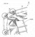
FIG. 25 shows aseat 90 for a straddled vehicle disclosed inFigure 2(A) and Figure 2(B) in Patent Document 1.FIG. 25(a) is a cross-sectional view showing a part of theseat 90, andFIG. 25(b) is a planar view showing a part of theseat 90 as seen from below. - The
seat 90 includes aseat base 91 and anouter cover member 92. Theseat base 91 includes abottom plate 93 and acushion member 94 located on thebottom plate 93. Theouter cover member 92 covers thecushion member 94. Theseat base 91 includes asitting plane 91a corresponding a sitting plane and aside wall 91b extending downward from a perimeter of thesitting plane 91a. - The
outer cover member 92 has a size larger than that of a surface of theseat base 91 such that a covering work is easily done. As shown in the figure, a peripheral portion of theouter cover member 92 is folded back at a tip of theside wall 91b of theseat base 91 and is secured to a back surface of theside wall 91b (back surface of the bottom plate 93) by staples 95 (is stapled). - The covering work of the
outer cover member 92 is performed as follows specifically. First, thesitting plane 91a of theseat base 91 is covered with theouter cover member 92. Next, the peripheral portion of theouter cover member 92 is pulled in a direction in which theside wall 91b extends. Then, in the state where the peripheral portion of theouter cover member 92 is pulled, theouter cover member 92 is folded back at the tip of theside wall 91b. Next, the peripheral portion of theouter cover member 92 overlapping the back surface of theside wall 91 is stapled by use of a tucker or the like. Thestaples 95 are driven sequentially along a circumferential direction in the state where theouter cover member 92 is pulled. In this step, a small number ofstaples 95 may be driven at a relatively large interval, so that theouter cover member 92 is temporarily secured. - Patent Document 1: Japanese Examined Utility Model Application Publication No.
H1-20232 - The
outer cover member 92 needs to be secured while being pulled at an appropriate force such that a portion overlapping thesitting plane 91a and a portion overlapping theside wall 91b are not wrinkled or broken. Since theouter cover member 92 has a size larger than that of the surface of theseat base 91 as described above, there is an extra portion in the peripheral portion of theouter cover member 92. As shown inFIG. 25(b) , this extra portion is secured by thestaples 95 while being partially folded up or is wrinkled betweenadjacent staples 95. - Unless the peripheral portion of the
outer cover member 92 is pulled properly (such that there is no variance in the tensile forced to be stapled, theouter cover member 92 may be wrinkled as floating in a portion thereof corresponding to (overlapping) the tip of theside wall 91b. More specifically, wrinkles may be continuously made from the extra portion to the tip of the folded portion of theouter cover member 92. - In other words, if two different tensile forces act on two continuous areas in the peripheral portion of the
outer cover member 92, the wrinkles from the extra portion of theouter cover member 92 are continued to the tip of the folded portion of theouter cover member 92. Such wrinkles are shown in an external appearance of theseat 90 and is visually recognizable, and thus deteriorates the appearance of theseat 90.FIG. 26 shows theseat 90 in the state where theouter cover member 92 is stapled to theseat base 91. As shown in the regions enclosed by the dashed lines inFIG. 26 , the tip of the folded portion of theouter cover member 92 may be wrinkled. - In the meantime, a textured portion including microscopic convex portions and concave portions may be formed in the outer cover member of the vehicle seat for the purpose of providing an effect of preventing slipping or for the purpose of improving the external appearance. The outer cover member having such a textured portion is easily deformed in a pulling direction from the concave portions, and thus is easily stretchable than an outer cover member having a smooth surface (namely, an outer cover member with no textured portion). Therefore, the outer cover member having the textured portion merely needs a relatively small force to be pulled, but is easily stretched in a different amount by a slightly different tensile force, which easily wrinkles the folded portion.
- The present invention made in light of the above-described problem has an object of providing a vehicle seat suppressing a tip of a folded portion of an outer cover member from being wrinkled.
- A vehicle seat in an embodiment according to the present invention includes a seat base including a plate member and a cushion member stacked on a surface of the plate member; and an outer cover member covering the cushion member, the outer cover member being secured to a back surface of the plate member. The seat base includes a rider support and a side wall extending in a thickness direction of the rider support from a perimeter of the rider support; the outer cover member includes a folded portion folded back at a tip of the side wall; the folded portion includes an outer region overlapping an outer side surface of the side wall, a tip region overlapping the tip of the side wall, and an inner region overlapping an inner side surface of the side wall; the outer cover member has a textured portion formed in the folded portion, the textured portion including a convex portion and a concave portion; the outer cover member further includes an ink layer in at least a part of the folded portion, the ink layer being continuously formed in the outer region, the tip region and the inner region, the ink layer being continuously formed on the convex portion and the concave portion of the textured portion; and a portion of the ink layer that is located on the concave portion has a thickness larger than that of a portion of the ink layer that is located on the convex portion.
- In an embodiment, the side wall of the seat base includes a rounded portion curved in a circumferential direction; and the outer cover member includes the ink layer at least in a region corresponding to the rounded portion in the folded portion.
- In an embodiment, the side wall of the seat base includes two areas that are continuous to each other and have different lengths in the thickness direction of the rider support; and the outer cover member includes the ink layer at least in a region corresponding to the two areas in the folded portion, the ink layer being continuously formed in the outer region, the tip region and the inner region.
- In an embodiment, the ink layer contains a resin material; and the outer cover member further includes an outer cover member main body supporting the ink layer, and an intermediate layer provided between the outer cover member main body and the ink layer, the intermediate layer containing a resin material of a same type as the resin material contained in the ink layer.
- In an embodiment, the resin material contained in the ink layer is an acrylic resin; and the intermediate layer contains an acrylic resin.
- In an embodiment, the portion of the ink layer that is located on the concave portion does not exceed a height from a trough of the concave portion to a peak of the convex portion.
- A vehicle in an embodiment according to the present invention includes the vehicle seat having any of the above-described structures.
- Hereinafter, functions and effects of an embodiment according to the present invention will be described.
- In the vehicle seat in an embodiment according to the present invention, the ink layer is continuously formed in the outer region, the tip region and the inner region in at least a part of the folded portion of the outer cover member. Therefore, as compared with a case where the ink layer is not formed, the rigidity of the folded portion (hereinafter, referred to as an "outer cover rigidity") is higher, and thus the following effects are provided.
- First, the ink layer formed in the tip region increases the outer cover rigidity of the tip region. Therefore, the tip region of the outer cover member is not easily deformed (floated). The ink layer continuously formed in the inner region and the tip region increases the outer cover rigidity of the inner region. Therefore, wrinkles in an extra portion of the inner region do not easily extend long. Namely, the wrinkles in the extra portion of the inner region are suppressed from being continued to the tip region. In addition, the ink layer is continuously formed in the outer region and the tip region. Therefore, the outer region has the outer cover rigidity thereof increased and thus plays a role of restricting the deformation (floating) of the tip region. Thus, the wrinkles continuous from the extra portion of the inner region to the tip region are more difficult to be formed. For the above-described reasons, in the vehicle seat according to the present invention, even if different tensile forces act on two continuous areas of a peripheral portion of the outer cover member, wrinkles are not easily formed in the tip region.
- In the case where the outer cover member has the textured portion, the folded portion is easily wrinkled. In the vehicle seat according to the present invention, the ink layer is continuously formed on the convex portion and the concave portion of the textured portion. Therefore, a portion of the ink layer located on the concave portion (continuous from a portion of the ink layer located on the convex portion) plays a role of limiting the convex portion (restricting the movement of the convex portion) . Therefore, although the outer cover member has the textured portion, the tip region is difficult to be wrinkled. In addition, the thickness of the portion of the ink layer located on the concave portion is larger than the thickness of the portion of the ink layer located on the convex portion. Therefore, the action of limiting the concave portion is made stronger, and thus the Lip region is more difficult to be wrinkled.
- In the case where the side wall of the seat base includes a rounded portion curved in a circumferential direction (i.e. , having a larger radius of curvature than the rest of the circumference), the extra portion is made large in a region of the outer cover member corresponding to the rounded portion. Therefore, during a work of securing the outer cover member to the plate member (performed while the outer cover member is pulled), it is made more difficult to deal with the extra portion in the region of the outer cover member corresponding to the rounded portion. Thus, it is preferred that the ink layer is formed in at least a region, corresponding to the rounded portion, of the folded portion of the outer cover member.
- In the case where the side wall of the seat base includes two areas that are continuous to each other and have different lengths in the thickness direction of the rider support, portions of the outer cover member corresponding to such areas have extra portions having different lengths in the thickness direction of the rider support. Therefore, wrinkles are easily formed in the extra portions. For this reason, it is preferred that the ink layer is formed in at least portions, corresponding to the areas, of the folded portion of the outer cover member.
- The outer cover member may further include an intermediate layer provided between the outer cover member main body and the ink layer. In the case where the intermediate layer contains a resin material of the same type as the resin material contained in the ink layer, the resin material in the intermediate layer and the resin material in the ink layer have a high level of affinity to each other. Therefore, the adhesion of the ink layer is increased. Such a high level of affinity also provides an effect of improving the ability of the ink layer of being colored.
- A preferable resin material contained in the ink layer is, for example, an acrylic resin. The acrylic resin has a high transparency and a high climate resistance. In the case where the ink layer contains an acrylic resin, the intermediate layer preferably contains a resin of the same type, namely, an acrylic resin.
- If the thickness of the portion of the ink layer located on the concave portion exceeds the height from the trough of the concave portion to the peak of the convex portion, the concave portion is completely filled with the ink layer. In this case, the touch of the textured portion (convex and concave portions) is changed. For this reason, it is preferred that the thickness of the portion of the ink layer located on the concave portion does not exceed the height from the trough of the concave portion to the peak of the convex portion.
- An embodiment of the present invention provides a vehicle seat suppressing a tip of a folded portion of an outer cover member from being wrinkled.
-
-
FIG. 1 is a side view schematically showing a straddled vehicle (motorcycle) 1 in an embodiment according to the present invention. -
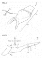
FIG. 2 is an isometric view schematically showing aseat 20 included in the motorcycle 1. -
FIG. 3 is a side view schematically showing theseat 20. -
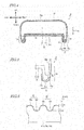
FIG. 4 is a cross-sectional view taken alongline 4A-4A' inFIG. 3 , schematically showing theseat 20. -
FIG. 5 is a cross-sectional view schematically showing aside wall 34 of aseat base 30 and the vicinity thereof. -
FIG. 6 schematically shows a cross-sectional structure of a folded portion 41 (outer region 41a,tip region 41b andinner region 41c) of anouter cover member 40. -
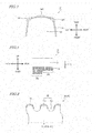
FIG. 7 is a planar view of a rear portion of theseat base 30 of theseat 20 as seen from below. -
FIG. 8 is a side view showing a part of theseat base 30. -
FIG. 9 is a cross-sectional view schematically showing an ink layer 50' formed by a screen printing method. -
FIG. 10(a) and FIG. 10(b) are each an optical micrograph showing an outer cover member (including no ink layer) having a textured portion of pattern A. -
FIG. 11(a) and FIG. 11(b) are each an optical micrograph showing an outer cover member (including no ink layer) having a textured portion of pattern B. -
FIG. 12(a) and FIG. 12(b) are each an optical micrograph showing an outer cover member having a textured portion of pattern A and including an ink layer formed by an inkjet method. -
FIG. 13(a) and FIG. 13(b) are each an optical micrograph showing an outer cover member having a textured portion of pattern B and including an ink layer formed by an inkjet method. -
FIG. 14(a) and FIG. 14(b) are each an optical micrograph showing an outer cover member having a textured portion of pattern A and including an ink layer formed by the screen printing method. -
FIG. 15(a) and FIG. 15(b) are each an optical micrograph showing an outer cover member having a textured portion of pattern B and including an ink layer formed by the screen printing method. -
FIG. 16(a), FIG. 16(b) and FIG. 16(c) are respectively graphs showing roughness curves of outer cover members having a textured portion of patter A, in the case where no ink layer is formed, in the case where an ink layer is formed by the inkjet method, and in the case where an ink layer is formed by the screen printing method. -
FIG. 17(a), FIG. 17(b) and FIG. 17(c) are respectively graphs showing roughness curves of outer cover members having a textured portion of patter B, in the case where no ink layer is formed, in the case where an ink layer is formed by the inkjet method, and in the case where an ink layer is formed by the screen printing method. -
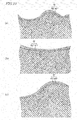
FIG. 18(a), FIG. 18(b) and FIG. 18(c) are each a schematic view showing a cross-sectional structure in the case where an ink layer is formed by the inkjet method on an outer cover member having a textured portion of pattern A. -
FIG. 19(a), FIG. 19(b) and FIG. 19(c) are each a schematic view showing a cross-sectional structure in the case where an ink layer is formed by the inkjet method on an outer cover member having a textured portion of pattern B. -
FIG. 20(a), FIG. 20(b) and FIG. 20(c) are each a schematic view showing a cross-sectional structure in the case where an ink layer is formed by the screen printing method on an outer cover member having a textured portion of pattern A. -
FIG. 21(a), FIG. 21(b) and FIG. 21(c) are each a schematic view showing a cross-sectional structure in the case where an ink layer is formed by the screen printing method on an outer cover member having a textured portion of pattern B. -
FIG. 22(a) shows anink layer 50 formed by the inkjet method, andFIG. 22(b) shows an ink layer 50' formed by the screen printing method. -
FIG. 23 is a cross-sectional view schematically showing theside wall 34 of theseat base 30 and the vicinity thereof. -
FIG. 24 is a cross-sectional view taken alongline 4A-4A' inFIG. 3 , schematically showing theseat 20. -
FIG. 25(a) and FIG. 25(b) are respectively a cross-sectional view and a planar view showing a part of a straddledvehicle seat 90 disclosed in Patent Document 1. -
FIG. 26 shows theseat 90 in the state where anouter cover member 92 is secured on aseat base 91 by stapling. - Hereinafter, embodiments of the present invention will be described with reference to the drawings. The present invention is not limited to any of the following embodiments.
-
FIG. 1 show a straddled vehicle 1 in this embodiment.FIG. 1 is a side view schematically showing the straddled vehicle 1. As shown inFIG. 1 , the straddled vehicle 1 is an on-load type motorcycle. In the following description and the drawings, the terms "front", "rear", "left", "right", "up" and "down" respectively refer to front, rear, left, right, up and down as seen from a rider of the motorcycle. - As shown in
FIG. 1 , the motorcycle 1 includes avehicle frame 2. Thevehicle frame 2 includes ahead pipe 3, amain frame 4, and a seat rail 5. Themain frame 4 extends obliquely rearward and downward from thehead pipe 3. The seat rail 5 extends obliquely rearward and slightly upward from themain frame 4. Aseat 20 is attached on the seat rail 5. Theseat 20 includes arider seat 20A on which the rider may sit and atandem seat 20B on which a passenger may sit. - A steering shaft (not shown) is inserted through the
head pipe 3. At a top end and a bottom end of the steering shaft, brackets (an upper bracket and an under bracket) 3a and 3b are respectively coupled. A pair of extendable front wheel support members 7 are coupled with thebrackets front wheel 8 is rotatably attached. - An
engine 9 is suspended to themain frame 4. At a rear end of themain frame 4, arear arm 11 is attached swingably as being centered around apivot shaft 10. At a rear end of therear arm 11, arear wheel 12 is rotatably attached. - Now, with reference to
FIG. 2, FIG. 3 andFIG. 4 , a structure of the seat (vehicle seat) 20 included in the motorcycle 1 will be described.FIG. 2, FIG. 3 andFIG. 4 are respectively an isometric view, a side view and a cross-sectional view schematically showing theseat 20.FIG. 4 shows a cross-section taken alongline 4A-4A' inFIG. 3 . - As shown in
FIG. 2, FIG. 3 andFIG. 4 , theseat 20 includes aseat base 30 and anouter cover member 40. As shown inFIG. 4 , theseat base 30 includes aplate member 31 and acushion member 32. For easier understanding,FIG. 4 shows the cross-sectional structure of theplate member 31 in a simplified manner. - The plate member (referred to also as a "bottom plate") 31 supports the
cushion member 32. Theplate member 31 forms a bottom portion of theseat 20, and has a role of providing a certain level of strength to the entirety of theseat 20. Therefore, theplate member 31 is preferably formed of a relatively highly rigid material. The material of theplate member 31 may be, specifically, a resin material such as polypropylene or the like. Theplate member 31 includes astay 31a and amount 31b securing theseat 20 to the seat rail 5. - The
cushion member 32 is stacked on asurface 31c of theplate member 31. Thecushion member 32 is preferably formed of a material that keeps having an appropriate level of resilience for a long time in order to keep providing a high level of comfort of riding. A preferable material of thecushion member 32 may be, for example, foamed polyurethane (urethane foam), but is not limited to this. - The
outer cover member 40 covers thecushion member 32. Theouter cover member 40 is stacked on asurface 32a of thecushion member 32. Theouter cover member 40 is secured to a back surface 31d of theplate member 31. Theouter cover member 40 may be secured to theplate member 31 by, for example, stapling. The outer cover member 40 (more precisely, an outer cover membermain body 40a described below) includes, for example, a base layer (lining; formed of, for example, wooly nylon) and a PVC (polyvinylchloride) layer (outer layer) covering a surface of the base layer, but is not limited to having such a structure, needless to say. For example, the outer cover membermain body 40a may be formed of, for example, synthetic leather, artificial leather, natural leather or the like. - As shown in
FIG. 4 , theseat base 30 includes arider support 33 supporting at least a part of the body of the rider. In this example, therider support 33 is a sitting plane that supports the buttocks of the rider. Theseat base 30 further includes aside wall 34 extending in a thickness direction TD of the sitting plane 33 (extending downward) from a perimeter of the sittingplane 33. - The
outer cover member 40 includes a foldedportion 41 folded inward from an outer side surface of theside wall 34 at a tip of theside wall 34. The foldedportion 41 includes anouter region 41a overlapping the outer side surface of theside wall 34, atip region 41b overlapping the tip of theside wall 34, and aninner region 41c overlapping an inner side surface of theside wall 34. In the state where theseat 20 is secured to the motorcycle 1, theouter region 41a is exposed outside of theseat 20 and is visually recognizable. By contrast, theinner region 41c is not exposed outside of theseat 20 and is not visually recognizable. -
FIG. 5 shows theside wall 34 and the vicinity thereof in enlargement. As shown inFIG. 5 , theouter cover member 40 includes anink layer 50 in the foldedportion 41. Hereinafter, aportion 40a of theouter cover member 40 other than the ink layer 50 (portion supporting the ink layer 50) will be referred to as the "outer cover member main body". Theink layer 50 is continuously formed in theouter region 41a, thetip region 41b and theinner region 41c of the foldedportion 41. In this example, theink layer 50 is also formed in a region other than the foldedportion 41, and is formed on substantially the entirety of a surface of the outer cover membermain body 40a. Theink layer 50 may be colored or transparent (i.e., non-colored). Theink layer 50 may have a stack structure including a colored layer and a transparent layer formed on the colored layer. -
FIG. 6 shows a cross-sectional structure of the foldedportion 41 of theouter cover member 40. Atextured portion 42 is formed in the foldedportion 41 of the outer cover member 40 (more specifically, formed at a surface of the folded portion 41). Thetextured portion 42 includes a plurality ofconvex portions 42a and a plurality ofconcave portions 42b. Thetextured portion 42 may be formed in a portion other than the foldedportion 41. In this embodiment, thetextured portion 42 is formed in substantially the entirety of theouter cover member 40. Thetextured portion 42 including theconvex portions 42a and theconcave portions 42b, which are microscopic, may provide theouter cover member 40 with an effect of preventing slipping or improve the external appearance of theouter cover member 40. There is no specific limitation on the size or the pitch of theconvex portions 42a or theconcave portions 42b of thetextured portion 42. A height difference between a peak of theconvex portions 42a and a trough of theconcave portions 42b is, for example, about 10 µm to about 110 µm. - As shown in
FIG. 6 , theink layer 50 is continuously formed on theconvex portions 42a and theconcave portions 42b of thetextured portion 41. Thickness d1 of aportion 50a of theink layer 50 located on theconvex portions 42a (hereinafter, such a portion will be referred to as a "convex region"), and thickness d2 of aportion 50b of theink layer 50 located on theconcave portions 42b (hereinafter, such a portion will be referred to as a "concave region"), are different from each other. Specifically, thickness d2 of theconcave region 50b of theink layer 50 is larger than thickness d1 of theconvex region 50a of theink layer 50. In this specification, the comparison between thickness d1 of theconvex region 50a of theink layer 50 and thickness d2 of theconcave region 50b of theink layer 50 is a comparison between the thickness of the region corresponding to the peak of theconvex portions 42a and the thickness of the region corresponding to the trough of theconcave portions 42b. Namely, unless otherwise specified, thickness d1 of theconvex region 50a is the thickness on the peak of theconvex portions 42a, and thickness d2 of theconcave region 50b is the thickness on the trough of theconcave portions 42b. The "peak" is a portion of theconvex portions 42a that protrudes most. The "trough" is a portion of theconcave portions 42b that is recessed most. - Thickness d1 of the
convex region 50a of theink layer 50 is, for example, 5 µm to 20 µm. Thickness d2 of theconcave region 50b of theink layer 50 is, for example, 20 µm to 50 µm. Needless to say, the thicknesses of theink layer 50 are not limited to the above. - As described above, in the seat (vehicle seat) 20 in this embodiment, the
ink layer 50 is continuously formed in theouter region 41a, thetip region 41b and theinner region 41c of the foldedportion 41 of theouter cover member 40. Therefore, as compared with a case where theink layer 50 is not formed, the rigidity of the folded portion 41 (rigidity of a stack structure including the outer cover membermain body 40a and theink layer 50; hereinafter, referred to as an "outer cover rigidity") is higher, and thus the following effects are provided. - First, the
ink layer 50 formed in thetip region 41b increases the outer cover rigidity of thetip region 41b. Therefore, thetip region 41b of theouter cover member 40 is not easily deformed (floated). Theink layer 50 continuously formed in theinner region 41c and thetip region 41b increases the outer cover rigidity of theinner region 41c. Therefore, wrinkles in an extra portion of theinner region 41c do not easily extend long. Namely, the wrinkles in the extra portion of theinner region 41c are suppressed from being continued to thetip region 41b. In addition, theink layer 50 is continuously formed in theouter region 41a and thetip region 41b. Therefore, theouter region 41a has the outer cover rigidity thereof increased and thus plays a role of restricting the deformation (floating) of thetip region 41b. Thus, the wrinkles continuous from the extra portion of theinner region 41c to thetip region 41b are more difficult to be formed. For the above-described reasons, in theseat 20 in this embodiment, even if different tensile forces act on two continuous areas of a peripheral portion of theouter cover member 40, wrinkles (as shown inFIG. 24 ) are not easily formed in thetip region 41b. - As described above, in the case where an outer cover member has a textured portion, a folded portion is easily wrinkled. In the
seat 20 in this embodiment, theink layer 50 is continuously formed on theconvex portions 42a and theconcave portions 42b of thetextured portion 42. Therefore, theconcave region 50b (continuous from theconvex region 50a) of theink layer 50 plays a role of limiting theconvex portions 42a in a left-right direction inFIG. 6 . In other words, theconcave region 50b of theink layer 50 restricts the movement of theconvex portions 42a in a pulling direction in which theouter cover member 40 is pulled to be secured to the seat base 30 (in the left-right direction inFIG. 6 ). Therefore, although theouter cover member 40 has the texturedportion 42, thetip region 41b is difficult to be wrinkled. In addition, in this embodiment, thickness d2 of theconcave region 50b of theink layer 50 is larger than thickness d1 of theconvex region 50a. Therefore, the action of limiting theconcave portions 42b is made stronger, and thus thetip region 41b is more difficult to be wrinkled. - The
ink layer 50 is preferably harder than the outer cover membermain body 40a. In the case where theink layer 50 is harder than the outer cover membermain body 40a, the outer cover rigidity of the foldedportion 40 is further increased. Thus, thetip region 41b is still more difficult to be wrinkled. - The
ink layer 50 does not need to be formed in substantially the entirety of theouter cover member 40. Theink layer 50 does not need to be formed in a region other than the foldedportion 41. The foldedportion 41 is present along substantially the entirety of a circumference of theseat 20, whereas theink layer 50 does not need to be formed in substantially the entirety of the foldedportion 41. As long as theink layer 50 is formed in at least a part of the foldedportion 41, a region of thetip region 41b where theink layer 50 is formed is suppressed from being wrinkled. In other words, it is preferred that theink layer 50 is formed in a region of thetip region 41b that would be easily wrinkled without theink layer 50. Hereinafter, a region where it is preferred that theink layer 50 is formed will be described specifically. - The
side wall 34 of theseat base 30 typically includes a rounded portion that is curved in the circumferential direction. Paying attention to a rear portion of theseat 20 shown inFIG. 2 , theside wall 34 includes a rounded portion in the rear portion of theseat 20. -
FIG. 7 shows the rear portion of theseat base 30 of theseat 20 as seen from below (detailed shape of theplate member 31 is omitted) . As shown inFIG. 7 , theside wall 34 of theseat base 30 includes threerounded portions 34R in a region corresponding to the rear portion of theseat 20. Therounded portions 34R are curved in the circumferential direction, namely, are curved as seen in a vertical direction. In other words, therounded portions 34R have a radius of curvature larger than the rest of the circumference of theside wall 34. The extra portion of theouter cover member 40 is made large in each of therounded portions 34R. Therefore, during a work of securing theouter cover member 40 to the plate member 31 (performed while theouter cover member 40 is pulled), it is made more difficult to deal with the extra portion. Thus, it is preferred that theink layer 50 is formed in at least regions, corresponding to therounded portions 34R, of the foldedportion 41 of theouter cover member 40. - The
side wall 34 of theseat base 30 may include two areas that are continuous to each other and have different lengths in the thickness direction TD of the sittingplane 33.FIG. 8 shows an example of such areas.FIG. 8 is a side view showing a part of theseat base 30. InFIG. 8 , for easier understanding, theplate member 31 and thecushion member 32 are integrally shown, and theside wall 34 is hatched (the sittingplane 33 is not hatched). - The two
areas FIG. 8 are continuous to each other in a front-rear direction and have different lengths L1 and L2 in the thickness direction TD of the sittingplane 33. In the case where theside wall 34 includessuch areas outer cover member 40 corresponding to theareas plane 33. Therefore, wrinkles are easily formed in the extra portions. For this reason, it is preferred that theink layer 50 is formed in at least portions, corresponding to theareas portion 41 of the outer cover member 40 (as described above, theink layer 50 is continuous in theouter region 41a, thetip region 41b and theinner region 41c). - The
ink layer 50 may decorate theouter cover member 40. Namely, theink layer 50 may exhibit a predetermined color, a predetermined letter, a predetermined pattern, a predetermined image or the like. As described above, in theseat 20 in this embodiment, theink layer 50 is formed even in theinner region 41c, which is not visually recognizable, of the foldedportion 41. In the case where theink layer 50 is formed even in a region that is not visually recognizable, the effect of suppressing generation of wrinkles is provided as described above. - If thickness d2 of the
concave region 50b of theink layer 50 exceeds the height from the trough of theconcave portions 42b to the peak of theconvex portions 42a, theconcave portions 42b are completely filled with theink layer 50. In this case, the touch of the textured portion (convex and concave portions) 42 is changed. For this reason, it is preferred that thickness d2 of theconcave region 50b of theink layer 50 does not exceed the height from the trough of theconcave portions 42b to the peak of theconvex portions 42a. - The
ink layer 50 is formed by a printing method. A preferably usable printing method may be, specifically, an inkjet method. A screen printing method is also a well known printing method. Studies made by the inventors of the present application have shown that with the screen printing method, it is difficult to form theink layer 50 continuously on the microscopicconvex portions 42a andconcave portions 42b of thetextured portion 42 as described above. -
FIG. 9 schematically shows an ink layer 50' formed by the screen printing method. In the case where the screen printing method is used, as shown inFIG. 9 , the ink layer 50' is formed on theconvex portions 42a but is not formed on theconcave portions 42b. A conceivable reason is the following. With the screen printing method, a relatively highly viscous ink material is extruded (rubbed) through holes of a screen by use of a squeegee. Therefore, the ink material is not easily attached to theconcave portions 42b, which are at a lower position than theconvex portions 42a. - By contrast, with the inkjet method, the ink material is injected from a nozzle of an inkjet printer as microscopic ink drops. Therefore, the ink material is attached to the
concave portions 42b as well as theconvex portions 42a. Thus, theink layer 50 is continuously formed on the microscopicconvex portions 42a and the microscopicconcave portions 42b of thetextured portion 42 in a preferred manner. In the case where the inkjet method is used, the viscosity or the like of the ink material may be appropriately adjusted (e.g., the ink material may be adjusted to have a low viscosity than that of the ink material used for the screen printing method), so that the ink material attached to theconvex portions 42a partially move to theconcave portions 42b by its own weight. Therefore, thickness d2 of the portion of theink layer 50 on theconcave portions 42b (thickness d2 of the concave region) is made larger than thickness d1 of the portion of theink layer 50 on theconvex portions 42a (thickness d1 of the convex region). - In the case where the inkjet method is used, examples of the usable ink material (material used to form the ink layer 50) include solvent-based ink, UV-based ink, and solvent-UV-based ink.
- The solvent-based ink contains a pigment, a resin acting as a binder (e.g., thermoplastic resin), and an organic solvent. In the case where the solvent-based ink is used, the solvent-based ink is attached onto the
outer cover member 40 and is heated to evaporate the organic solvent (is thermally dried) to form theink layer 50. Theink layer 50 formed by use of the solvent-based ink has a high climate resistance. - The UV-based ink contains a pigment, a photopolymerizable monomer and/or oligomer as a precursor of a resin acting as a binder, and a photoinitiator. In the case where the UV-based ink is used, the UV-based ink is attached onto the
outer cover member 40 and is irradiated with ultraviolet to form theink layer 50. Theink layer 50 formed by use of the UV-based ink has a high rub fastness. - The solvent-UV-based ink contains both of the components of the solvent-based ink and the components of the UV-based ink. The solvent-UV-based ink, for example, dilutes a polymer compound with a solvent to provide viscosity and also rub fastness and climate resistance. In the case where the solvent-UV-based ink is used, the solvent-UV-based ink is attached onto the
outer cover member 40, and is irradiated with ultraviolet and thermally dried to form theink layer 50. Theink layer 50 formed by use of the solvent-UV-based ink has both of a high climate resistance and a high rub fastness. - Whichever ink may be used, the
resultant ink layer 50 contains a resin material. A preferable resin material contained in the ink layer is, for example, an acrylic resin. The acrylic resin has a high transparency and a high climate resistance. Whichever ink may be used, the pigment, among the above-described components, may be removed to make the ink transparent. - The
textured portion 42 may be formed in theouter cover member 40 by any of various known texturing methods. - Now, an ink layer was formed by the inkjet method on an outer cover member having a textured portion, and separately, an ink layer was formed by the screen printing method on an outer cover member having a textured portion. In each case, an external appearance of the outer cover member including the ink layer was observed. The results will be described.
- Outer cover members having textured portions of two patterns shown in
FIG. 10 and FIG. 11 were prepared.FIG. 10 and FIG. 11 are each an optical micrograph of such an outer cover member (the ink layer is not formed) . As seen from the scale bars in the figures,FIG. 10(b) and FIG. 11(b) are of a higher magnification thanFIG. 10(a) and FIG. 11(a) . - The textured portion of the outer cover member shown in
FIG. 10(a) and FIG. 10(b) has a satin finish with a relatively small size and a relatively small pitch of the convex portions and the concave portions (hereinafter, such a pattern will be referred to as a "pattern A") . The textured portion of the outer cover member shown inFIG. 11(a) and FIG. 11(b) has a larger size and a larger pitch of the convex portions and the concave portions than those of pattern A (hereinafter, such a pattern will be referred to as a "pattern B"). -
FIG. 12 and FIG. 13 show optical micrographs of the outer cover members each including an ink layer formed by the inkjet method. It is seen fromFIG. 12(a), FIG. 12(b), FIG. 13(a) and FIG. 13(b) that even after the ink layer is formed, the external appearance of each outer cover member sufficiently reflects the convex and concave shape of the textured portion below the ink layer. Namely, it is seen that the textured portion is not completely filled with the ink layer. -
FIG. 14 and FIG. 15 show optical micrographs of the outer cover members each including an ink layer formed by the screen printing method. It is seen fromFIG. 14(a), FIG. 14(b), FIG. 15(a) and FIG. 15(b) that in this case also, the external appearance of each outer cover member reflects the convex and concave shape of the textured portion. However, as seen from a comparison ofFIG. 13(a) and FIG. 13(b) againstFIG. 15(a) and FIG. 15(b) , in the case where the screen printing method is used, the contrast in the micrograph is more conspicuous than in the case where the inkjet method is used. This is caused because the ink layer is formed only on the convex portions of the textured portion but is not formed on the concave portions. - Now, on each of an outer cover member including no ink layer, an outer cover member including an ink layer formed by the inkjet method, and an outer cover member including an ink layer formed by the screen printing method, the convex and concave shape was measured by a surface roughness meter. The results will be described.
-
FIG. 16(a), FIG. 16(b) and FIG. 16(c) respectively show roughness curves of an outer cover member including no ink layer, an outer cover member including an ink layer formed by the inkjet method, and an outer cover member including an ink layer formed by the screen printing method. All the outer cover members have the textured portion of pattern A.FIG. 16(a), FIG. 16(b) and FIG. 16(c) also each show the maximum height (the largest height difference between the peak and the trough) of the roughness curve. This is applicable toFIG. 17 described below. The "roughness" refers to the height of a waviness of the convex and concave portions of the outer cover member. - From a comparison between
FIG. 16(a) and FIG. 16(b) , it is seen that the height difference is smaller in the case where the ink layer is formed by the inkjet method than in the case where no ink layer is formed. A reason for this is that in the case where the ink layer is formed by the inkjet method, the thickness of a portion of the ink layer that corresponds to the concave portions of the textured portion is larger than the thickness of a portion of the ink layer that corresponds to the convex portions of the textured portion. - From a comparison between
FIG. 16(a) and FIG. 16(c) , it is seen that the height difference is larger in the case where the ink layer is formed by the screen printing method than in the case where no ink layer is formed. A reason for this is that in the case where the ink layer is formed by the screen printing method, the ink layer is formed on the convex portions of the textured portion but is not formed on the concave portions of the textured portion. -
FIG. 17(a), FIG. 17(b) and FIG. 17(c) respectively show roughness curves of an outer cover member including no ink layer, an outer cover member including an ink layer formed by the inkjet method, and an outer cover member including an ink layer formed by the screen printing method. All the outer cover members have the textured portion of pattern B. - From a comparison between
FIG. 17(a), FIG. 17(b) and FIG. 17(c) , it is seen that the outer cover members having the textured portion of patter B have the same tendency as that of the outer cover members having the textured portion of pattern A. - Now, on each of an outer cover member including an ink layer formed by the inkjet method and an outer cover member including an ink layer formed by the screen printing method, the cross-sectional structure was observed. The results will be described.
-
FIG. 16(a) ,FIG. 18(b) and FIG. 18(c) are schematic views showing the cross-sectional structure of the ink layer formed by the inkjet method on the outer cover member having the textured portion of pattern A.FIG. 18(b) and FIG. 18(c) show the cross-sectional structure at a larger scale than that inFIG. 18(a). FIG. 18(b) and FIG. 18(c) show the cross-sectional structure at the same scale. In the example shown inFIG. 18(a), FIG. 18(b) and FIG. 18(c) , theink layer 50 has a stack structure including acolor layer 50C and atransparent layer 50T stacked on thecolor layer 50C. The same is applicable to the example shown inFIG. 19 described below. - From
FIG. 18(a) , it is seen that the ink layer is continuously formed on the convex portions and the concave portions of the textured portion. FromFIG. 18(b) and FIG. 18(c) , it is seen that the portion of the ink layer that is located on the concave portions has a thickness larger than that of the portion of the ink layer that is located on the convex portions. -
FIG. 19(a), FIG. 19(b) and FIG. 19(c) are schematic views showing the cross-sectional structure of the ink layer formed by the inkjet method on the outer cover member having the textured portion of pattern B.FIG. 19(b) and FIG. 19(c) show the cross-sectional structure at a larger scale than that inFIG. 19(a) . FIG. 19(b) and FIG. 19(c) show the cross-sectional structure at the same scale. - From
FIG. 19(a) , it is seen that the ink layer is continuously formed on the convex portions and the concave portions of the textured portion. FromFIG. 19(b) and FIG. 19(c) , it is seen that the portion of the ink layer that is located on the concave portions has a thickness larger than that of the portion of the ink layer that is located on the convex portions. -
FIG. 20(a), FIG. 20(b) and FIG. 20(c) are schematic views showing the cross-sectional structure of the ink layer formed by the screen printing method on the outer cover member having the textured portion of pattern A.FIG. 20(b) and FIG. 20(c) show the cross-sectional structure at a larger scale than that inFIG. 20(a). FIG. 20(b) and FIG. 20(c) show the cross-sectional structure at the same scale. In the example shown inFIG. 20(a), FIG. 20(b) and FIG. 20(c) , the ink layer 50' has a stack structure including acolor layer 50C' and atransparent layer 50T' stacked on thecolor layer 50C'. The same is applicable to the example shown inFIG. 21 described below. - From
FIG. 20(a), FIG. 20(b) and FIG. 20(c) , it is seen that the ink layer is formed on the convex portions of the textured portion but is not much formed on the concave portions (the ink layer is thin) . -
FIG. 21(a), FIG. 21(b) and FIG. 21(c) are schematic views showing the cross-sectional structure of the ink layer formed by the screen printing method on the outer cover member having the textured portion of pattern B.FIG. 21(b) and FIG. 21(c) show the cross-sectional structure at a larger scale than that inFIG. 21(a). FIG. 21(b) and FIG. 21(c) show the cross-sectional structure at the same scale. - From
FIG. 21(a), FIG. 21(b) andFIG. 21(c) , it is seen that the ink layer is formed on the convex portions of the textured portion but is not much formed on the concave portions (the ink layer is thin) . - It is seen from the above description made with reference to
FIG. 12 through FIG. 21 , use of the inkjet method allows theink layer 50 to be preferably formed continuously on theconvex portions 42a and theconcave portions 42b of thetextured portion 42. - Now, with reference to
FIG. 22(a) and FIG. 22(b) , a difference in the surface structure between the ink layer formed by the inkjet method and the ink layer formed by the screen printing method, more specifically, a difference in microscopic ruggedness at the surface (hereinafter, referred to as the "microscopic ruggedness" or the "microscopic roughness") between the two ink layers, will be described.FIG. 22(a) shows theink layer 50 formed by the inkjet method, andFIG. 22(b) shows the ink layer 50' formed by the screen printing method. - As seen from a comparison between
FIG. 22(a) and FIG. 22(b) , a microscopic ruggedness u (microscopic roughness) at the surface of theink layer 50 formed by the inkjet method is smaller than that of the surface of the ink layer 50' formed by the screen printing method. More specifically, in theink layer 50 formed by the inkjet method, the microscopic ruggedness u of each of thecolored layer 50C and thetransparent layer 50T is smaller. - The "microscopic ruggedness" refers to the smoothness of the surface of the ink layer that follows the textured pattern of the outer cover member main body. More specifically, the "microscopic ruggedness" refers to the height of the ink layer from a line obtained as a result of the waviness of the convex and concave portions at the surface of the outer cover member main body being corrected to a straight line (average line of the waviness) in a cross-section of the seat taken along the thickness direction. As the height of the ink layer is lower, the smoothness is lower. Namely, the expression that the "microscopic ruggedness is smaller" indicates that the height, from the surface of the waviness of the ink layer, of the microscopic ruggedness that is convex and concave in a direction normal to the surface is small.
- As described above, the ink layer formed by the inkjet method has a small microscopic ruggedness (microscopic roughness) of the surface thereof. Therefore, cracks starting from the surface are not easily continued, and thus the rigidity and the durability are increased.
- In the above, a structure in which the
ink layer 50 is directly formed on the outer cover membermain body 40a is described. Theseat 20 in this embodiment is not limited to having such a structure. As shown inFIG. 23 , theouter cover member 40 may further include an intermediate layer (underlying layer) 51 provided between the outer cover membermain body 40a and theink layer 50. Theintermediate layer 51 may be formed of, for example, a resin material. In the case where theintermediate layer 51 contains a resin material of the same type as the resin material contained in theink layer 50, the resin material in theintermediate layer 51 and the resin material in theink layer 50 have a high level of affinity to each other. Therefore, the adhesion of theink layer 50 is increased. Such a high level of affinity also provides an effect of improving the color exhibiting ability of theink layer 50. For example, in the case where theink layer 50 contains an acrylic resin, theintermediate layer 51 preferably contains a resin of the same type, namely, an acrylic resin. -
FIG. 4 and the like show the shape of theplate member 31 in a simplified manner. There is no specific limitation on the shape of theplate member 31 as long as theplate member 31 allows theseat base 30 to include theside wall 34.FIG. 24 shows an example of shape of theplate member 31.FIG. 24 is a cross-sectional view schematically showing theseat 20, taken alongline 4A-4A' inFIG. 3 . In the example shown inFIG. 24 , the sittingplane 33 of theplate member 31 includes a plurality of regions having different heights (namely, includes a stepped portion) . As can be seen, theplate member 31 may have any of various shapes in accordance with the structure of the seat rail 5. - The motorcycle 1 shown in
FIG. 1 is of an on-load type. The straddled vehicle in this embodiment may be of a so-called off-road type, a moped type, a scooter type or any other type. The term "straddled vehicle" refers to any vehicle on which a rider rides astride, and is not limited to a two-wheel vehicle. The straddled vehicle may be, for example, a three-wheel vehicle (LMW), the vehicle body of which is inclined to change the advancing direction. - The present invention is not limited to being applicable to the seat of a straddled vehicle, and may be applicable to a vehicle seat widely. For example, the present invention is usable for a seat of a four-wheel automobile.
- In the above, the
rider support 33 is the sitting plane. The rider support does not need to be the sitting plane. In a seat including a backrest or a headrest, the rider support may be a portion that supports the back of the rider or a portion that supports the head of the rider. - An embodiment according to the present invention provides a vehicle seat that suppresses a tip of a folded portion of an outer cover member from being wrinkled. An embodiment according to the present invention is preferably usable for a seat of any of various types of vehicles.
-
- 1 Motorcycle (straddled vehicle)
- 20 Seat
- 30 Seat base
- 31 Plate member
- 32 Cushion member
- 33 Rider support (sitting plane)
- 34 Side wall
- 40 Outer cover member
- 40a Outer cover member main body
- 41 Folded portion
- 41a Outer region
- 41b Tip region
- 41c Inner region
- 42 Textured portion
- 42a Convex portion
- 42b Concave portion
- 50 Ink layer
- 50a Convex region of the ink layer (portion located on the convex portions of the textured portion)
- 50b Concave region of the ink layer (portion located on the concave portions of the textured portion)
- 51 Intermediate portion
Claims (7)
- A vehicle seat, comprising:a seat base including a plate member and a cushion member stacked on a surface of the plate member; andan outer cover member covering the cushion member, the outer cover member being secured to a rear surface of the plate member;
wherein:the seat base includes a rider support and a side wall extending in a thickness direction of the rider support from a perimeter of the rider support;the outer cover member includes a folded portion folded back at a tip of the side wall;the folded portion includes an outer region overlapping an outer side surface of the side wall, a tip region overlapping the tip of the side wall, and an inner region overlapping an inner side surface of the side wall;the outer cover member has a textured portion formed in the folded portion, the textured portion including a convex portion and a concave portion;the outer cover member further includes an ink layer in at least a part of the folded portion, the ink layer being continuously formed in the outer region, the tip region and the inner region, the ink layer being continuously formed on the convex portion and the concave portion of the textured portion; anda portion of the ink layer that is located on the concave portion has a thickness larger than that of a portion of the ink layer that is located on the convex portion. - The vehicle seat according to claim 1, wherein:the side wall of the seat base includes a rounded portion curved in a circumferential direction; andthe outer cover member includes the ink layer at least in a region corresponding to the rounded portion in the folded portion.
- The vehicle seat according to claim 1 or 2, wherein:the side wall of the seat base includes two areas that are continuous to each other and have different lengths in the thickness direction of the rider support; andthe outer cover member includes the ink layer at least in a region corresponding to the two areas in the folded portion, the ink layer being continuously formed in the outer region, the tip region and the inner region.
- The vehicle seat according to any one of claims 1 through 3, wherein:the ink layer contains a resin material; andthe outer cover member further includes an outer cover member main body supporting the ink layer, and an intermediate layer provided between the outer cover member main body and the ink layer, the intermediate layer containing a resin material of a same type as the resin material contained in the ink layer.
- The vehicle seat according to claim 4, wherein:the resin material contained in the ink layer is an acrylic resin; andthe intermediate layer contains an acrylic resin.
- The vehicle seat according to any one of claims 1 through 5, wherein the portion of the ink layer that is located on the concave portion does not exceed a height from a trough of the concave portion to a peak of the convex portion.
- A vehicle, comprising the vehicle seat according to any one of claims 1 through 6.
Applications Claiming Priority (2)
| Application Number | Priority Date | Filing Date | Title |
|---|---|---|---|
| JP2016145914 | 2016-07-26 | ||
| PCT/JP2017/026718 WO2018021251A1 (en) | 2016-07-26 | 2017-07-24 | Vehicle seat and vehicle |
Publications (3)
| Publication Number | Publication Date |
|---|---|
| EP3492357A1 true EP3492357A1 (en) | 2019-06-05 |
| EP3492357A4 EP3492357A4 (en) | 2019-08-28 |
| EP3492357B1 EP3492357B1 (en) | 2020-09-30 |
Family
ID=61016108
Family Applications (1)
| Application Number | Title | Priority Date | Filing Date |
|---|---|---|---|
| EP17834257.2A Active EP3492357B1 (en) | 2016-07-26 | 2017-07-24 | Vehicle seat and vehicle |
Country Status (3)
| Country | Link |
|---|---|
| EP (1) | EP3492357B1 (en) |
| PH (1) | PH12018550012B1 (en) |
| WO (1) | WO2018021251A1 (en) |
Cited By (1)
| Publication number | Priority date | Publication date | Assignee | Title |
|---|---|---|---|---|
| DE102021130096A1 (en) | 2021-11-18 | 2023-05-25 | Bayerische Motoren Werke Aktiengesellschaft | Seat device for a tilting vehicle and tilting vehicle with such a seat device |
Family Cites Families (9)
| Publication number | Priority date | Publication date | Assignee | Title |
|---|---|---|---|---|
| JP3069070B2 (en) * | 1997-12-01 | 2000-07-24 | 恵和株式会社 | Method of manufacturing ink jet recording sheet |
| JP4824610B2 (en) * | 2007-03-19 | 2011-11-30 | テイ・エス テック株式会社 | Outdoor vehicle seat |
| JP5215832B2 (en) * | 2008-12-08 | 2013-06-19 | テイ・エス テック株式会社 | Motorcycle seat |
| US20130017356A1 (en) * | 2010-03-18 | 2013-01-17 | Johnson Controls Technology Company | Soft component with decorative surface finish |
| JP5749482B2 (en) * | 2010-12-09 | 2015-07-15 | テイ・エス テック株式会社 | Stretched vehicle |
| JP6209334B2 (en) * | 2013-02-08 | 2017-10-04 | テイ・エス テック株式会社 | Vehicle seat |
| JP6353833B2 (en) * | 2013-07-05 | 2018-07-04 | セーレン株式会社 | Synthetic leather for automobiles |
| JP6357367B2 (en) * | 2014-06-30 | 2018-07-11 | 株式会社イノアックコーポレーション | Skin material and its manufacturing method |
| JP6440460B2 (en) * | 2014-11-07 | 2018-12-19 | ダイキョーニシカワ株式会社 | Interior parts for vehicles |
-
2017
- 2017-07-24 PH PH1/2018/550012A patent/PH12018550012B1/en unknown
- 2017-07-24 EP EP17834257.2A patent/EP3492357B1/en active Active
- 2017-07-24 WO PCT/JP2017/026718 patent/WO2018021251A1/en not_active Ceased
Cited By (1)
| Publication number | Priority date | Publication date | Assignee | Title |
|---|---|---|---|---|
| DE102021130096A1 (en) | 2021-11-18 | 2023-05-25 | Bayerische Motoren Werke Aktiengesellschaft | Seat device for a tilting vehicle and tilting vehicle with such a seat device |
Also Published As
| Publication number | Publication date |
|---|---|
| WO2018021251A1 (en) | 2018-02-01 |
| PH12018550012A1 (en) | 2018-07-30 |
| PH12018550012B1 (en) | 2024-01-05 |
| EP3492357A4 (en) | 2019-08-28 |
| EP3492357B1 (en) | 2020-09-30 |
Similar Documents
| Publication | Publication Date | Title |
|---|---|---|
| JP7197578B2 (en) | motorcycle seat arrangement | |
| TWI538840B (en) | Support element for human body and method for its realisation | |
| US3269773A (en) | Cycle seats | |
| CH706858A2 (en) | Breathable saddle for cycles, motor cycles and other pedal vehicles, promotes the flow of air through the saddle to the body | |
| CN201086768Y (en) | Large goods shelf of motorcycle overlapped with plastic cladding element | |
| EP3492357B1 (en) | Vehicle seat and vehicle | |
| EP2428408B1 (en) | Vehicle upholstery member | |
| JP2013018363A (en) | Saddle type vehicle | |
| EP3492358B1 (en) | Vehicle seat and vehicle | |
| KR20130033365A (en) | Soft component with decorative surface finish | |
| CN1265993C (en) | Saddle of motorcycle | |
| EP1880897A3 (en) | Backrest for a motor vehicle seat | |
| EP0706933B1 (en) | Motorcycle seat | |
| CN105745146B (en) | Straddle-type vehicle | |
| EP4494985A1 (en) | Three-dimensional bicycle saddle structure | |
| US20090064917A1 (en) | Kayak and Canoe seat | |
| US20250026423A1 (en) | Three-dimensional bicycle saddle structure | |
| TWI286109B (en) | Protection cover for car body cover | |
| JP6362928B2 (en) | Seats for two and three-wheeled vehicles | |
| KR102210249B1 (en) | Supplementary back for motorcycle | |
| EP3009335B1 (en) | Exterior cover for straddled vehicles | |
| JP5115074B2 (en) | Vehicle seat | |
| JP5749482B2 (en) | Stretched vehicle | |
| CN217864468U (en) | Tricycle saddle | |
| USD520913S1 (en) | Seven passenger pedaled vehicle |
Legal Events
| Date | Code | Title | Description |
|---|---|---|---|
| STAA | Information on the status of an ep patent application or granted ep patent |
Free format text: STATUS: THE INTERNATIONAL PUBLICATION HAS BEEN MADE |
|
| PUAI | Public reference made under article 153(3) epc to a published international application that has entered the european phase |
Free format text: ORIGINAL CODE: 0009012 |
|
| STAA | Information on the status of an ep patent application or granted ep patent |
Free format text: STATUS: REQUEST FOR EXAMINATION WAS MADE |
|
| 17P | Request for examination filed |
Effective date: 20180216 |
|
| AK | Designated contracting states |
Kind code of ref document: A1 Designated state(s): AL AT BE BG CH CY CZ DE DK EE ES FI FR GB GR HR HU IE IS IT LI LT LU LV MC MK MT NL NO PL PT RO RS SE SI SK SM TR |
|
| AX | Request for extension of the european patent |
Extension state: BA ME |
|
| A4 | Supplementary search report drawn up and despatched |
Effective date: 20190731 |
|
| RIC1 | Information provided on ipc code assigned before grant |
Ipc: B62J 1/12 20060101AFI20190725BHEP Ipc: B32B 27/18 20060101ALI20190725BHEP Ipc: B60N 2/58 20060101ALI20190725BHEP Ipc: B41J 2/01 20060101ALI20190725BHEP Ipc: A47C 31/02 20060101ALI20190725BHEP |
|
| DAV | Request for validation of the european patent (deleted) | ||
| DAX | Request for extension of the european patent (deleted) | ||
| GRAP | Despatch of communication of intention to grant a patent |
Free format text: ORIGINAL CODE: EPIDOSNIGR1 |
|
| STAA | Information on the status of an ep patent application or granted ep patent |
Free format text: STATUS: GRANT OF PATENT IS INTENDED |
|
| INTG | Intention to grant announced |
Effective date: 20200529 |
|
| GRAS | Grant fee paid |
Free format text: ORIGINAL CODE: EPIDOSNIGR3 |
|
| GRAA | (expected) grant |
Free format text: ORIGINAL CODE: 0009210 |
|
| STAA | Information on the status of an ep patent application or granted ep patent |
Free format text: STATUS: THE PATENT HAS BEEN GRANTED |
|
| AK | Designated contracting states |
Kind code of ref document: B1 Designated state(s): AL AT BE BG CH CY CZ DE DK EE ES FI FR GB GR HR HU IE IS IT LI LT LU LV MC MK MT NL NO PL PT RO RS SE SI SK SM TR |
|
| REG | Reference to a national code |
Ref country code: CH Ref legal event code: EP Ref country code: GB Ref legal event code: FG4D |
|
| REG | Reference to a national code |
Ref country code: DE Ref legal event code: R096 Ref document number: 602017024770 Country of ref document: DE Ref country code: AT Ref legal event code: REF Ref document number: 1318527 Country of ref document: AT Kind code of ref document: T Effective date: 20201015 |
|
| REG | Reference to a national code |
Ref country code: IE Ref legal event code: FG4D |
|
| PG25 | Lapsed in a contracting state [announced via postgrant information from national office to epo] |
Ref country code: FI Free format text: LAPSE BECAUSE OF FAILURE TO SUBMIT A TRANSLATION OF THE DESCRIPTION OR TO PAY THE FEE WITHIN THE PRESCRIBED TIME-LIMIT Effective date: 20200930 Ref country code: BG Free format text: LAPSE BECAUSE OF FAILURE TO SUBMIT A TRANSLATION OF THE DESCRIPTION OR TO PAY THE FEE WITHIN THE PRESCRIBED TIME-LIMIT Effective date: 20201230 Ref country code: SE Free format text: LAPSE BECAUSE OF FAILURE TO SUBMIT A TRANSLATION OF THE DESCRIPTION OR TO PAY THE FEE WITHIN THE PRESCRIBED TIME-LIMIT Effective date: 20200930 Ref country code: NO Free format text: LAPSE BECAUSE OF FAILURE TO SUBMIT A TRANSLATION OF THE DESCRIPTION OR TO PAY THE FEE WITHIN THE PRESCRIBED TIME-LIMIT Effective date: 20201230 Ref country code: GR Free format text: LAPSE BECAUSE OF FAILURE TO SUBMIT A TRANSLATION OF THE DESCRIPTION OR TO PAY THE FEE WITHIN THE PRESCRIBED TIME-LIMIT Effective date: 20201231 Ref country code: HR Free format text: LAPSE BECAUSE OF FAILURE TO SUBMIT A TRANSLATION OF THE DESCRIPTION OR TO PAY THE FEE WITHIN THE PRESCRIBED TIME-LIMIT Effective date: 20200930 |
|
| REG | Reference to a national code |
Ref country code: AT Ref legal event code: MK05 Ref document number: 1318527 Country of ref document: AT Kind code of ref document: T Effective date: 20200930 |
|
| PG25 | Lapsed in a contracting state [announced via postgrant information from national office to epo] |
Ref country code: RS Free format text: LAPSE BECAUSE OF FAILURE TO SUBMIT A TRANSLATION OF THE DESCRIPTION OR TO PAY THE FEE WITHIN THE PRESCRIBED TIME-LIMIT Effective date: 20200930 Ref country code: LV Free format text: LAPSE BECAUSE OF FAILURE TO SUBMIT A TRANSLATION OF THE DESCRIPTION OR TO PAY THE FEE WITHIN THE PRESCRIBED TIME-LIMIT Effective date: 20200930 |
|
| REG | Reference to a national code |
Ref country code: NL Ref legal event code: MP Effective date: 20200930 |
|
| REG | Reference to a national code |
Ref country code: LT Ref legal event code: MG4D |
|
| PG25 | Lapsed in a contracting state [announced via postgrant information from national office to epo] |
Ref country code: RO Free format text: LAPSE BECAUSE OF FAILURE TO SUBMIT A TRANSLATION OF THE DESCRIPTION OR TO PAY THE FEE WITHIN THE PRESCRIBED TIME-LIMIT Effective date: 20200930 Ref country code: PT Free format text: LAPSE BECAUSE OF FAILURE TO SUBMIT A TRANSLATION OF THE DESCRIPTION OR TO PAY THE FEE WITHIN THE PRESCRIBED TIME-LIMIT Effective date: 20210201 Ref country code: CZ Free format text: LAPSE BECAUSE OF FAILURE TO SUBMIT A TRANSLATION OF THE DESCRIPTION OR TO PAY THE FEE WITHIN THE PRESCRIBED TIME-LIMIT Effective date: 20200930 Ref country code: EE Free format text: LAPSE BECAUSE OF FAILURE TO SUBMIT A TRANSLATION OF THE DESCRIPTION OR TO PAY THE FEE WITHIN THE PRESCRIBED TIME-LIMIT Effective date: 20200930 Ref country code: LT Free format text: LAPSE BECAUSE OF FAILURE TO SUBMIT A TRANSLATION OF THE DESCRIPTION OR TO PAY THE FEE WITHIN THE PRESCRIBED TIME-LIMIT Effective date: 20200930 Ref country code: SM Free format text: LAPSE BECAUSE OF FAILURE TO SUBMIT A TRANSLATION OF THE DESCRIPTION OR TO PAY THE FEE WITHIN THE PRESCRIBED TIME-LIMIT Effective date: 20200930 |
|
| PG25 | Lapsed in a contracting state [announced via postgrant information from national office to epo] |
Ref country code: AL Free format text: LAPSE BECAUSE OF FAILURE TO SUBMIT A TRANSLATION OF THE DESCRIPTION OR TO PAY THE FEE WITHIN THE PRESCRIBED TIME-LIMIT Effective date: 20200930 Ref country code: AT Free format text: LAPSE BECAUSE OF FAILURE TO SUBMIT A TRANSLATION OF THE DESCRIPTION OR TO PAY THE FEE WITHIN THE PRESCRIBED TIME-LIMIT Effective date: 20200930 Ref country code: ES Free format text: LAPSE BECAUSE OF FAILURE TO SUBMIT A TRANSLATION OF THE DESCRIPTION OR TO PAY THE FEE WITHIN THE PRESCRIBED TIME-LIMIT Effective date: 20200930 Ref country code: PL Free format text: LAPSE BECAUSE OF FAILURE TO SUBMIT A TRANSLATION OF THE DESCRIPTION OR TO PAY THE FEE WITHIN THE PRESCRIBED TIME-LIMIT Effective date: 20200930 Ref country code: IS Free format text: LAPSE BECAUSE OF FAILURE TO SUBMIT A TRANSLATION OF THE DESCRIPTION OR TO PAY THE FEE WITHIN THE PRESCRIBED TIME-LIMIT Effective date: 20210130 |
|
| PG25 | Lapsed in a contracting state [announced via postgrant information from national office to epo] |
Ref country code: NL Free format text: LAPSE BECAUSE OF FAILURE TO SUBMIT A TRANSLATION OF THE DESCRIPTION OR TO PAY THE FEE WITHIN THE PRESCRIBED TIME-LIMIT Effective date: 20200930 Ref country code: SK Free format text: LAPSE BECAUSE OF FAILURE TO SUBMIT A TRANSLATION OF THE DESCRIPTION OR TO PAY THE FEE WITHIN THE PRESCRIBED TIME-LIMIT Effective date: 20200930 |
|
| REG | Reference to a national code |
Ref country code: DE Ref legal event code: R097 Ref document number: 602017024770 Country of ref document: DE |
|
| PLBE | No opposition filed within time limit |
Free format text: ORIGINAL CODE: 0009261 |
|
| STAA | Information on the status of an ep patent application or granted ep patent |
Free format text: STATUS: NO OPPOSITION FILED WITHIN TIME LIMIT |
|
| PG25 | Lapsed in a contracting state [announced via postgrant information from national office to epo] |
Ref country code: DK Free format text: LAPSE BECAUSE OF FAILURE TO SUBMIT A TRANSLATION OF THE DESCRIPTION OR TO PAY THE FEE WITHIN THE PRESCRIBED TIME-LIMIT Effective date: 20200930 |
|
| 26N | No opposition filed |
Effective date: 20210701 |
|
| PG25 | Lapsed in a contracting state [announced via postgrant information from national office to epo] |
Ref country code: SI Free format text: LAPSE BECAUSE OF FAILURE TO SUBMIT A TRANSLATION OF THE DESCRIPTION OR TO PAY THE FEE WITHIN THE PRESCRIBED TIME-LIMIT Effective date: 20200930 |
|
| REG | Reference to a national code |
Ref country code: CH Ref legal event code: PL |
|
| GBPC | Gb: european patent ceased through non-payment of renewal fee |
Effective date: 20210724 |
|
| PG25 | Lapsed in a contracting state [announced via postgrant information from national office to epo] |
Ref country code: MC Free format text: LAPSE BECAUSE OF FAILURE TO SUBMIT A TRANSLATION OF THE DESCRIPTION OR TO PAY THE FEE WITHIN THE PRESCRIBED TIME-LIMIT Effective date: 20200930 |
|
| REG | Reference to a national code |
Ref country code: BE Ref legal event code: MM Effective date: 20210731 |
|
| PG25 | Lapsed in a contracting state [announced via postgrant information from national office to epo] |
Ref country code: LI Free format text: LAPSE BECAUSE OF NON-PAYMENT OF DUE FEES Effective date: 20210731 Ref country code: GB Free format text: LAPSE BECAUSE OF NON-PAYMENT OF DUE FEES Effective date: 20210724 Ref country code: CH Free format text: LAPSE BECAUSE OF NON-PAYMENT OF DUE FEES Effective date: 20210731 |
|
| PG25 | Lapsed in a contracting state [announced via postgrant information from national office to epo] |
Ref country code: IS Free format text: LAPSE BECAUSE OF FAILURE TO SUBMIT A TRANSLATION OF THE DESCRIPTION OR TO PAY THE FEE WITHIN THE PRESCRIBED TIME-LIMIT Effective date: 20210130 Ref country code: LU Free format text: LAPSE BECAUSE OF NON-PAYMENT OF DUE FEES Effective date: 20210724 |
|
| PG25 | Lapsed in a contracting state [announced via postgrant information from national office to epo] |
Ref country code: IE Free format text: LAPSE BECAUSE OF NON-PAYMENT OF DUE FEES Effective date: 20210724 Ref country code: BE Free format text: LAPSE BECAUSE OF NON-PAYMENT OF DUE FEES Effective date: 20210731 |
|
| PG25 | Lapsed in a contracting state [announced via postgrant information from national office to epo] |
Ref country code: CY Free format text: LAPSE BECAUSE OF FAILURE TO SUBMIT A TRANSLATION OF THE DESCRIPTION OR TO PAY THE FEE WITHIN THE PRESCRIBED TIME-LIMIT Effective date: 20200930 |
|
| P01 | Opt-out of the competence of the unified patent court (upc) registered |
Effective date: 20230527 |
|
| PG25 | Lapsed in a contracting state [announced via postgrant information from national office to epo] |
Ref country code: HU Free format text: LAPSE BECAUSE OF FAILURE TO SUBMIT A TRANSLATION OF THE DESCRIPTION OR TO PAY THE FEE WITHIN THE PRESCRIBED TIME-LIMIT; INVALID AB INITIO Effective date: 20170724 |
|
| PG25 | Lapsed in a contracting state [announced via postgrant information from national office to epo] |
Ref country code: MK Free format text: LAPSE BECAUSE OF FAILURE TO SUBMIT A TRANSLATION OF THE DESCRIPTION OR TO PAY THE FEE WITHIN THE PRESCRIBED TIME-LIMIT Effective date: 20200930 |
|
| PG25 | Lapsed in a contracting state [announced via postgrant information from national office to epo] |
Ref country code: TR Free format text: LAPSE BECAUSE OF FAILURE TO SUBMIT A TRANSLATION OF THE DESCRIPTION OR TO PAY THE FEE WITHIN THE PRESCRIBED TIME-LIMIT Effective date: 20200930 |
|
| PG25 | Lapsed in a contracting state [announced via postgrant information from national office to epo] |
Ref country code: MT Free format text: LAPSE BECAUSE OF FAILURE TO SUBMIT A TRANSLATION OF THE DESCRIPTION OR TO PAY THE FEE WITHIN THE PRESCRIBED TIME-LIMIT Effective date: 20200930 |
|
| PGFP | Annual fee paid to national office [announced via postgrant information from national office to epo] |
Ref country code: DE Payment date: 20250722 Year of fee payment: 9 |
|
| PGFP | Annual fee paid to national office [announced via postgrant information from national office to epo] |
Ref country code: IT Payment date: 20250724 Year of fee payment: 9 |
|
| PGFP | Annual fee paid to national office [announced via postgrant information from national office to epo] |
Ref country code: FR Payment date: 20250725 Year of fee payment: 9 |