EP3492283A1 - Tire tread comprising a stabilizer structure - Google Patents
Tire tread comprising a stabilizer structure Download PDFInfo
- Publication number
- EP3492283A1 EP3492283A1 EP18207946.7A EP18207946A EP3492283A1 EP 3492283 A1 EP3492283 A1 EP 3492283A1 EP 18207946 A EP18207946 A EP 18207946A EP 3492283 A1 EP3492283 A1 EP 3492283A1
- Authority
- EP
- European Patent Office
- Prior art keywords
- tread
- main groove
- tire
- subgroove
- sidewall
- Prior art date
- Legal status (The legal status is an assumption and is not a legal conclusion. Google has not performed a legal analysis and makes no representation as to the accuracy of the status listed.)
- Granted
Links
Images



Classifications
-
- B—PERFORMING OPERATIONS; TRANSPORTING
- B60—VEHICLES IN GENERAL
- B60C—VEHICLE TYRES; TYRE INFLATION; TYRE CHANGING; CONNECTING VALVES TO INFLATABLE ELASTIC BODIES IN GENERAL; DEVICES OR ARRANGEMENTS RELATED TO TYRES
- B60C11/00—Tyre tread bands; Tread patterns; Anti-skid inserts
- B60C11/03—Tread patterns
- B60C11/12—Tread patterns characterised by the use of narrow slits or incisions, e.g. sipes
- B60C11/1204—Tread patterns characterised by the use of narrow slits or incisions, e.g. sipes with special shape of the sipe
- B60C11/1218—Three-dimensional shape with regard to depth and extending direction
-
- B—PERFORMING OPERATIONS; TRANSPORTING
- B60—VEHICLES IN GENERAL
- B60C—VEHICLE TYRES; TYRE INFLATION; TYRE CHANGING; CONNECTING VALVES TO INFLATABLE ELASTIC BODIES IN GENERAL; DEVICES OR ARRANGEMENTS RELATED TO TYRES
- B60C11/00—Tyre tread bands; Tread patterns; Anti-skid inserts
- B60C11/03—Tread patterns
- B60C11/032—Patterns comprising isolated recesses
- B60C11/0323—Patterns comprising isolated recesses tread comprising channels under the tread surface, e.g. for draining water
-
- B—PERFORMING OPERATIONS; TRANSPORTING
- B60—VEHICLES IN GENERAL
- B60C—VEHICLE TYRES; TYRE INFLATION; TYRE CHANGING; CONNECTING VALVES TO INFLATABLE ELASTIC BODIES IN GENERAL; DEVICES OR ARRANGEMENTS RELATED TO TYRES
- B60C11/00—Tyre tread bands; Tread patterns; Anti-skid inserts
- B60C11/03—Tread patterns
- B60C11/04—Tread patterns in which the raised area of the pattern consists only of continuous circumferential ribs, e.g. zig-zag
- B60C11/042—Tread patterns in which the raised area of the pattern consists only of continuous circumferential ribs, e.g. zig-zag further characterised by the groove cross-section
-
- B—PERFORMING OPERATIONS; TRANSPORTING
- B60—VEHICLES IN GENERAL
- B60C—VEHICLE TYRES; TYRE INFLATION; TYRE CHANGING; CONNECTING VALVES TO INFLATABLE ELASTIC BODIES IN GENERAL; DEVICES OR ARRANGEMENTS RELATED TO TYRES
- B60C11/00—Tyre tread bands; Tread patterns; Anti-skid inserts
- B60C11/03—Tread patterns
- B60C11/12—Tread patterns characterised by the use of narrow slits or incisions, e.g. sipes
- B60C11/1236—Tread patterns characterised by the use of narrow slits or incisions, e.g. sipes with special arrangements in the tread pattern
- B60C11/125—Tread patterns characterised by the use of narrow slits or incisions, e.g. sipes with special arrangements in the tread pattern arranged at the groove bottom
-
- B—PERFORMING OPERATIONS; TRANSPORTING
- B60—VEHICLES IN GENERAL
- B60C—VEHICLE TYRES; TYRE INFLATION; TYRE CHANGING; CONNECTING VALVES TO INFLATABLE ELASTIC BODIES IN GENERAL; DEVICES OR ARRANGEMENTS RELATED TO TYRES
- B60C11/00—Tyre tread bands; Tread patterns; Anti-skid inserts
- B60C11/03—Tread patterns
- B60C11/12—Tread patterns characterised by the use of narrow slits or incisions, e.g. sipes
- B60C11/1204—Tread patterns characterised by the use of narrow slits or incisions, e.g. sipes with special shape of the sipe
- B60C2011/1213—Tread patterns characterised by the use of narrow slits or incisions, e.g. sipes with special shape of the sipe sinusoidal or zigzag at the tread surface
-
- B—PERFORMING OPERATIONS; TRANSPORTING
- B60—VEHICLES IN GENERAL
- B60C—VEHICLE TYRES; TYRE INFLATION; TYRE CHANGING; CONNECTING VALVES TO INFLATABLE ELASTIC BODIES IN GENERAL; DEVICES OR ARRANGEMENTS RELATED TO TYRES
- B60C2200/00—Tyres specially adapted for particular applications
- B60C2200/06—Tyres specially adapted for particular applications for heavy duty vehicles
Definitions
- the present invention relates to a tread for a tire and more specifically to a tread for a pneumatic tire such as a truck tire.
- a construction is adopted in conventional pneumatic tires in which, when a cross-section is viewed from a tire meridian direction, a contact patch of a shoulder rib arches and forms a convex on an inner side of a tire radial direction. Due to this construction, contact pressure of the tire is distributed evenly over a center region and a shoulder region of a tread portion and uneven wear of the tire may be suppressed.
- the invention relates to a tread in accordance with claim 1, to a tire in accordance with claim 8 and to a method in accordance with claim 9.
- a tread for a tire in accordance with one embodiment of the present invention includes a first circumferential main groove, a second circumferential main groove, a third circumferential main groove, and a fourth circumferential main groove.
- the fourth main groove has a stabilizing structure for increasing tread stiffness.
- the stabilizing structure has a circumferentially extending wavy subgroove in a radially innermost bottom of the fourth circumferential main groove.
- the subgroove has a curved, cylindrical radially innermost surface for mitigating cracking and increasing axial flexibility of the stabilizing structures.
- an axial width of the subgroove shrinks to 0.0 mm under a predetermined operating condition.
- the subgroove has a first sidewall and a second sidewall interconnected by the curved, cylindrical radially innermost surface of the subgroove.
- the first sidewall abuts the second sidewall under the predetermined operating condition.
- relative motion between the first sidewall and the second sidewall is prevented by a wavy configuration of the first sidewall and a corresponding wavy configuration of the second sidewall.
- a method in accordance with the present invention stiffens a tire tread.
- the method comprises the steps of: extending a first circumferential main groove across the tire tread; extending a second circumferential main groove across the tire tread; circumferentially extending a wavy subgroove across a radially innermost cylindrical bottom surface of the first main groove; and curving a radially innermost surface of the subgroove.
- the radially innermost surface of the subgroove being radially inside the radially innermost cylindrical bottom surface of the first main groove. sidewall under the predetermined operating condition.
- a system in accordance with the present invention increases cornering stiffness of a tire tread.
- the system includes a first circumferential main groove, a second circumferential main groove, and a stabilizing structure for increasing tread stiffness.
- the stabilizing structure has a circumferentially extending wavy subgroove in a radially innermost bottom of the first main groove.
- the subgroove has a curved, cylindrical radially innermost surface for mitigating cracking and increasing axial flexibility of the stabilizing structures.
- “Circumferential” means lines or directions extending along the perimeter of the surface of the annular tire parallel to the Equatorial Plane (EP) and perpendicular to the axial direction; it can also refer to the direction of the sets of adjacent circular curves whose radii define the axial curvature of the tread, as viewed in cross section.
- “Groove” means an elongated void area in a tread that may extend circumferentially or laterally about the tread in a straight, curved, or zigzag manner. Circumferentially and laterally extending grooves sometimes have common portions.
- the "groove width" may be the tread surface occupied by a groove or groove portion divided by the length of such groove or groove portion; thus, the groove width may be its average width over its length.
- Grooves may be of varying depths in a tire. The depth of a groove may vary around the circumference of the tread, or the depth of one groove may be constant but vary from the depth of another groove in the tire. If such narrow or wide grooves are of substantially reduced depth as compared to wide circumferential grooves, which they interconnect, they may be regarded as forming "tie bars" tending to maintain a rib-like character in the tread region involved.
- Ring and radially are used to mean directions radially toward or away from the axis of rotation of the tire.
- Ring means a circumferentially extending strip of rubber on the tread which is defined by at least one, preferably circumferential groove and either a second such groove or a lateral edge.
- the strip may be laterally undivided by full-depth grooves.
- “Sipe” or “incision” means small slots molded into the tread elements of the tire that subdivide the tread surface and improve traction; sipes may be designed to close when within the contact patch or footprint.
- Thread means a molded rubber component which, when bonded to a tire casing, includes that portion of the tire that comes into contact with the road when the tire is normally inflated and under normal load.
- Thread element or “traction element” means a rib or a block element.
- Thread width means the arc length of the tread surface in a plane including the axis of rotation of the tire.
- the axial width of the circumferential shoulder ribs 18 is each preferably in a range of from 2% to 10%, more preferably 3% to 7% of overall the axial width of the tread 11.
- the narrow circumferential shoulder ribs 18 are preferably sacrificial ribs.
- the tire 10 is a truck tire.
- the shoulder grooves 28 have curved, in cross-section preferably cylindrical or hemispherical radially innermost surfaces 29 to mitigate cracking (see FIG. 5 ).
- the shoulder grooves 28 In cross-section, the shoulder grooves 28 overall preferably have a key-hole shape with a widened, basically rain drop shaped or circular radial inner portion.
- the width of the shoulder grooves 28 at their radially outermost portion is preferably in a range of from 0.7 mm to 3 mm, more preferably 1-2 mm.
- the narrow shoulder ribs 18 are preferably radially recessed from the main tread portion as shown in Fig. 4 .
- This recess is preferably in a range from 0.5 to 2 mm. Accordingly, there is a respective step in the tread 11 at the shoulder groove 28 when moving axially from the shoulder rib 18 towards the equatorial plane of the tire 10.
- the main tread portion is preferably defined by a pair of intermediate circumferential first ribs 12, a pair of intermediate circumferential second ribs 14, and one or more center circumferential third ribs 16.
- the intermediate circumferential first ribs 12 are each defined by the respective shoulder groove 18 and a respective first circumferential groove 22.
- the intermediate circumferential second ribs 14 are each defined by the respective first circumferential groove 22 and a respective second circumferential groove 24.
- the center circumferential third rib 16 is defined by the second circumferential grooves 24.
- the first circumferential groove 22 serve as stabilizing circumferential grooves 22.
- the two second or central circumferential grooves 24 preferably each have a trapezoidal cross-section with slanted walls and a flat bottom ( FIG. 4 ).
- the slanted walls preferably make an angle with the equatorial plane of the tire 10 in a range of from 10 to 30 degrees, more preferably 15 to 25 degrees.
- the radial depth of the second or central circumferential grooves 24 is preferably in a range of from 12 to 20 mm and/or in a range of from 80% to 100% or from 90% to 100% of the non-skid depth of the tread 11.
- the intermediate circumferential second ribs 14 and the center intermediate circumferential third rib 16 preferably each have wavy blind sipes 15, 17, respectively, for improving performance of the tread 11.
- the two first circumferential grooves 22 preferably also have a trapezoidal cross-section with slanted walls and a flat bottom, similar to the two central circumferential grooves 24.
- the slanted walls preferably again make an angle with the equatorial plane of the tire 10 in a range of from 10 to 30 degrees, more preferably 15 to 25 degrees.
- each of the two first circumferential grooves 22 is shallower or less than the depth of the central circumferential grooves 24.
- the radial depth of each of the two first circumferential grooves 22 is preferably 50% or about 50% of the central groove depths ( FIG. 4 ). In another embodiment, the radial depth of each of the two first circumferential grooves 22 is in a range of from 40% to 70% or 40% to 60% of the central groove depths.
- each of the two first circumferential grooves 22 is a stabilizing structure 220.
- the stabilizing structures 220 are defined circumferentially extending wavy or sinusoidal subgrooves 222 in the bottoms of the grooves 22.
- the wavelength of the wavy or sinusoidal subgrooves 222 in the circumferential direction is preferably in a range of from 8 to 50 mm, more preferably 10 to 40 mm.
- both the axial width of the subgrooves 222 and the axial width of the wave or sinusoidal pattern of the subgrooves 222, i.e. twice their amplitude, is preferably be less than the axial width of the bottoms of the circumferential grooves 22.
- the axial width of the subgrooves 222 is in a range of from 5 to 25%, more preferably 10 to 20%, of the axial width of the bottoms of the circumferential grooves 22.
- the axial width of the wave or sinusoidal pattern of the subgrooves 222 is in a range of from 25 to 80%, more preferably 30 to 50%, of the axial width of the bottoms of the circumferential grooves 22.
- the subgrooves 222 preferably extend into curved, in cross-section preferably cylindrical or hemispherical radially innermost surfaces 229 to mitigate cracking and to increase axial flexibility of the stabilizing structures 222 ( FIG. 5 ).
- the subgrooves 222 together with the radially innermost surfaces 229 overall preferably have a key-hole shape with a widened, basically rain drop shaped or round radial inner portion.
- the axial width of the radially innermost surfaces 229 is preferably in a range of from 70 to 110%, more preferably 90 to 100%, of the axial width of the bottoms of the circumferential grooves 22. More
- the total radial depth of the two first circumferential grooves 22 including the radial depth of the subgrooves 222 and the innermost structures 229 is preferably in a range of from 90% to 110%, more preferably 100% or about 100% of the radial depth of the center or second circumferential grooves 24.
- the axial width of the subgrooves 222 may shrink to as little as 0.0 mm (e.g., touching). Because of the wavy pattern of the subgrooves 222, the walls of the subgrooves may interlock thereby preventing relative circumferential movement between the walls of the subgrooves 222. This may provide an increase in stiffness of the tread 11 while cornering, without requiring increased overall stiffness of the tread during straight line movement of the vehicle.
- the relatively narrow sacrificial shoulder ribs 18 may remain recessed to maintain a sharp edge at the axially or laterally outer edges of first ribs 12.
- the narrow shoulder ribs 18 may deflect into the first ribs 12 during lateral maneuvers of the vehicle in order to laterally support the first ribs 12.
- These narrow shoulder ribs 18 may hence have a coupling effect with the first ribs 12 to maintain a flat lateral or transverse profile of the footprint of the tread 11.
- the narrow shoulder ribs 18 preferably wear at essentially the same rate as the main tread portion thereby maintaining a stable radial recess or offset distance from the main tread profile ( FIG. 5 ).
Landscapes
- Engineering & Computer Science (AREA)
- Mechanical Engineering (AREA)
- Tires In General (AREA)
Abstract
Description
- The present invention relates to a tread for a tire and more specifically to a tread for a pneumatic tire such as a truck tire.
- A construction is adopted in conventional pneumatic tires in which, when a cross-section is viewed from a tire meridian direction, a contact patch of a shoulder rib arches and forms a convex on an inner side of a tire radial direction. Due to this construction, contact pressure of the tire is distributed evenly over a center region and a shoulder region of a tread portion and uneven wear of the tire may be suppressed.
- The invention relates to a tread in accordance with claim 1, to a tire in accordance with claim 8 and to a method in accordance with claim 9.
- Dependent claims refer to preferred embodiments of the invention.
- A tread for a tire in accordance with one embodiment of the present invention includes a first circumferential main groove, a second circumferential main groove, a third circumferential main groove, and a fourth circumferential main groove. The fourth main groove has a stabilizing structure for increasing tread stiffness. The stabilizing structure has a circumferentially extending wavy subgroove in a radially innermost bottom of the fourth circumferential main groove.
- According to a preferred aspect of the tread, the subgroove has a curved, cylindrical radially innermost surface for mitigating cracking and increasing axial flexibility of the stabilizing structures.
- According to still another preferred aspect of the tread, an axial width of the subgroove shrinks to 0.0 mm under a predetermined operating condition.
- According to yet another preferred aspect of the tread, the subgroove has a first sidewall and a second sidewall interconnected by the curved, cylindrical radially innermost surface of the subgroove.
- According to still another preferred aspect of the tread, the first sidewall abuts the second sidewall under the predetermined operating condition.
- According to yet another preferred aspect of the tread, relative motion between the first sidewall and the second sidewall is prevented by a wavy configuration of the first sidewall and a corresponding wavy configuration of the second sidewall.
- A method in accordance with the present invention stiffens a tire tread. In accordance with one embodiment of the present invention, the method comprises the steps of: extending a first circumferential main groove across the tire tread; extending a second circumferential main groove across the tire tread; circumferentially extending a wavy subgroove across a radially innermost cylindrical bottom surface of the first main groove; and curving a radially innermost surface of the subgroove. The radially innermost surface of the subgroove being radially inside the radially innermost cylindrical bottom surface of the first main groove. sidewall under the predetermined operating condition.
- A system in accordance with the present invention increases cornering stiffness of a tire tread. The system includes a first circumferential main groove, a second circumferential main groove, and a stabilizing structure for increasing tread stiffness. The stabilizing structure has a circumferentially extending wavy subgroove in a radially innermost bottom of the first main groove.
- According to a preferred aspect of the system, the subgroove has a curved, cylindrical radially innermost surface for mitigating cracking and increasing axial flexibility of the stabilizing structures.
- "Axial" and "axially" are used herein to refer to lines or directions that are parallel to the axis of rotation of the tire.
- "Circumferential" means lines or directions extending along the perimeter of the surface of the annular tire parallel to the Equatorial Plane (EP) and perpendicular to the axial direction; it can also refer to the direction of the sets of adjacent circular curves whose radii define the axial curvature of the tread, as viewed in cross section.
- "Groove" means an elongated void area in a tread that may extend circumferentially or laterally about the tread in a straight, curved, or zigzag manner. Circumferentially and laterally extending grooves sometimes have common portions.
- The "groove width" may be the tread surface occupied by a groove or groove portion divided by the length of such groove or groove portion; thus, the groove width may be its average width over its length. Grooves may be of varying depths in a tire. The depth of a groove may vary around the circumference of the tread, or the depth of one groove may be constant but vary from the depth of another groove in the tire. If such narrow or wide grooves are of substantially reduced depth as compared to wide circumferential grooves, which they interconnect, they may be regarded as forming "tie bars" tending to maintain a rib-like character in the tread region involved.
- "Radial" and "radially" are used to mean directions radially toward or away from the axis of rotation of the tire.
- "Rib" means a circumferentially extending strip of rubber on the tread which is defined by at least one, preferably circumferential groove and either a second such groove or a lateral edge. The strip may be laterally undivided by full-depth grooves.
- "Sipe" or "incision" means small slots molded into the tread elements of the tire that subdivide the tread surface and improve traction; sipes may be designed to close when within the contact patch or footprint.
- "Tread" means a molded rubber component which, when bonded to a tire casing, includes that portion of the tire that comes into contact with the road when the tire is normally inflated and under normal load.
- "Tread element" or "traction element" means a rib or a block element.
- "Tread width" means the arc length of the tread surface in a plane including the axis of rotation of the tire.
- The present invention will be better understood through reference to the following description and the appended drawings, in which:
-
FIG. 1 is a schematic perspective view of a tire in accordance with the present invention. -
FIG. 2 is a schematic orthogonal view of the tread of the tire ofFIG. 1 . -
FIG. 3 is a schematic detail view of the tread ofFIG. 2 . -
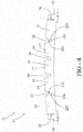
FIG. 4 is a schematic section view taken along the line "4-4" inFIG. 2 . -
FIG. 5 is a schematic detail drawing of a shoulder area ofFIG. 4 . - Referring now in more detail to the drawings, the present invention will below be described in more detail.
- A
pneumatic tire 10, which could also be a non-pneumatic tire, is illustrated inFIGS. 1-5 and has atread 11 with relatively narrowcircumferential shoulder ribs 18 defined bycircumferential shoulder grooves 28 at the lateral edges of the main tread portion. The axial width of thecircumferential shoulder ribs 18 is each preferably in a range of from 2% to 10%, more preferably 3% to 7% of overall the axial width of thetread 11. The narrowcircumferential shoulder ribs 18 are preferably sacrificial ribs. Preferably, thetire 10 is a truck tire. - The
shoulder grooves 28 have curved, in cross-section preferably cylindrical or hemispherical radiallyinnermost surfaces 29 to mitigate cracking (seeFIG. 5 ). In cross-section, theshoulder grooves 28 overall preferably have a key-hole shape with a widened, basically rain drop shaped or circular radial inner portion. The width of theshoulder grooves 28 at their radially outermost portion is preferably in a range of from 0.7 mm to 3 mm, more preferably 1-2 mm. - The
narrow shoulder ribs 18 are preferably radially recessed from the main tread portion as shown inFig. 4 . This recess is preferably in a range from 0.5 to 2 mm. Accordingly, there is a respective step in thetread 11 at theshoulder groove 28 when moving axially from theshoulder rib 18 towards the equatorial plane of thetire 10. - The main tread portion is preferably defined by a pair of intermediate circumferential
first ribs 12, a pair of intermediate circumferentialsecond ribs 14, and one or more center circumferentialthird ribs 16. - The intermediate circumferential
first ribs 12 are each defined by therespective shoulder groove 18 and a respective firstcircumferential groove 22. - The intermediate circumferential
second ribs 14 are each defined by the respective firstcircumferential groove 22 and a respective secondcircumferential groove 24. - The center circumferential
third rib 16 is defined by the secondcircumferential grooves 24. - The first
circumferential groove 22 serve as stabilizingcircumferential grooves 22. - The two second or central
circumferential grooves 24 preferably each have a trapezoidal cross-section with slanted walls and a flat bottom (FIG. 4 ). The slanted walls preferably make an angle with the equatorial plane of thetire 10 in a range of from 10 to 30 degrees, more preferably 15 to 25 degrees. - The radial depth of the second or central
circumferential grooves 24 is preferably in a range of from 12 to 20 mm and/or in a range of from 80% to 100% or from 90% to 100% of the non-skid depth of thetread 11. - The intermediate circumferential
second ribs 14 and the center intermediate circumferentialthird rib 16 preferably each have wavyblind sipes tread 11. - The two first
circumferential grooves 22 preferably also have a trapezoidal cross-section with slanted walls and a flat bottom, similar to the two centralcircumferential grooves 24. The slanted walls preferably again make an angle with the equatorial plane of thetire 10 in a range of from 10 to 30 degrees, more preferably 15 to 25 degrees. - As shown in
FIG. 4 , the radial depth of each of the two firstcircumferential grooves 22 is shallower or less than the depth of the centralcircumferential grooves 24. - The radial depth of each of the two first
circumferential grooves 22 is preferably 50% or about 50% of the central groove depths (FIG. 4 ). In another embodiment, the radial depth of each of the two firstcircumferential grooves 22 is in a range of from 40% to 70% or 40% to 60% of the central groove depths. - At the flat bottom of each of the two first
circumferential grooves 22 is a stabilizingstructure 220. - The stabilizing
structures 220 are defined circumferentially extending wavy orsinusoidal subgrooves 222 in the bottoms of thegrooves 22. The wavelength of the wavy orsinusoidal subgrooves 222 in the circumferential direction is preferably in a range of from 8 to 50 mm, more preferably 10 to 40 mm. - As shown in
FIG. 3 , both the axial width of thesubgrooves 222 and the axial width of the wave or sinusoidal pattern of thesubgrooves 222, i.e. twice their amplitude, is preferably be less than the axial width of the bottoms of thecircumferential grooves 22. - Preferably, the axial width of the
subgrooves 222 is in a range of from 5 to 25%, more preferably 10 to 20%, of the axial width of the bottoms of thecircumferential grooves 22. - Preferably, the axial width of the wave or sinusoidal pattern of the
subgrooves 222 is in a range of from 25 to 80%, more preferably 30 to 50%, of the axial width of the bottoms of thecircumferential grooves 22. - The
subgrooves 222 preferably extend into curved, in cross-section preferably cylindrical or hemispherical radiallyinnermost surfaces 229 to mitigate cracking and to increase axial flexibility of the stabilizing structures 222 (FIG. 5 ). Hence, thesubgrooves 222 together with the radiallyinnermost surfaces 229 overall preferably have a key-hole shape with a widened, basically rain drop shaped or round radial inner portion. The axial width of the radiallyinnermost surfaces 229 is preferably in a range of from 70 to 110%, more preferably 90 to 100%, of the axial width of the bottoms of thecircumferential grooves 22. More - The total radial depth of the two first
circumferential grooves 22 including the radial depth of thesubgrooves 222 and theinnermost structures 229 is preferably in a range of from 90% to 110%, more preferably 100% or about 100% of the radial depth of the center or secondcircumferential grooves 24. - When an axially inward load is placed on the
tread 11, such as while the vehicle is cornering, the axial width of thesubgrooves 222 may shrink to as little as 0.0 mm (e.g., touching). Because of the wavy pattern of thesubgrooves 222, the walls of the subgrooves may interlock thereby preventing relative circumferential movement between the walls of thesubgrooves 222. This may provide an increase in stiffness of thetread 11 while cornering, without requiring increased overall stiffness of the tread during straight line movement of the vehicle. - During normal running of the vehicle, the relatively narrow
sacrificial shoulder ribs 18 may remain recessed to maintain a sharp edge at the axially or laterally outer edges offirst ribs 12. Thenarrow shoulder ribs 18 may deflect into thefirst ribs 12 during lateral maneuvers of the vehicle in order to laterally support thefirst ribs 12. Thesenarrow shoulder ribs 18 may hence have a coupling effect with thefirst ribs 12 to maintain a flat lateral or transverse profile of the footprint of thetread 11. - The
narrow shoulder ribs 18 preferably wear at essentially the same rate as the main tread portion thereby maintaining a stable radial recess or offset distance from the main tread profile (FIG. 5 ).
Claims (10)
- A tread for a tire (10), the tread (11) comprising:a first circumferential main groove (24); anda second circumferential main groove (22), the second circumferential main groove (22) comprising a stabilizing structure (220) comprising a circumferentially extending wavy or sinusoidal subgroove (222) in a radially innermost bottom of the fourth circumferential main groove (22).
- The tread as set forth in claim 1 wherein the subgroove (222) has a in cross-section curved, cylindrical or hemispherical radially innermost surface (229).
- The tread as set forth in claim 1 or 2 wherein an axial width of the subgroove (222) is such that it shrinks to 0.0 mm under predetermined operating conditions of the tire (10).
- The tread as set forth in at least one of the previous claims wherein the subgroove (222) has a first sidewall and a second sidewall interconnected by the curved innermost surface (229) of the subgroove (222).
- The tread as set forth in claim 4 wherein the first sidewall abuts the second sidewall under predetermined operating conditions of the tire.
- The tread as set forth in claim 5 wherein relative motion between the first sidewall and the second sidewall is prevented or reduced by a wavy configuration of the first sidewall and a corresponding wavy configuration of the second sidewall.
- The tread as set forth in at least one of the previous claims, wherein the tread (11) further comprises a third circumferential main groove (24) and a fourth circumferential main groove (22).
- A tire comprising the tread (11) in accordance with at least one of the previous claims.
- A method for stiffening a tire tread, the method comprising the steps of:extending a first circumferential main groove (22) across the tire tread (11);extending a second circumferential main groove (24) across the tire tread (11);circumferentially extending a wavy or sinusoidal subgroove (222) across a radially innermost bottom surface of the first main groove (22); andcurving a radially innermost surface of the subgroove (222), the radially innermost surface (229) of the subgroove (222) being radially inside the radially innermost bottom surface of the first main groove (22).
- The method as set forth in claim 8 wherein curved radially innermost surface (229) of the subgroove (222) mitigates cracking and increases axial flexibility of the first main groove (22).
Applications Claiming Priority (1)
| Application Number | Priority Date | Filing Date | Title |
|---|---|---|---|
| US15/828,541 US11701925B2 (en) | 2017-12-01 | 2017-12-01 | Stabilizer structure for a tread of a tire |
Publications (2)
| Publication Number | Publication Date |
|---|---|
| EP3492283A1 true EP3492283A1 (en) | 2019-06-05 |
| EP3492283B1 EP3492283B1 (en) | 2020-10-07 |
Family
ID=64456793
Family Applications (1)
| Application Number | Title | Priority Date | Filing Date |
|---|---|---|---|
| EP18207946.7A Active EP3492283B1 (en) | 2017-12-01 | 2018-11-23 | Tire tread comprising a stabilizer structure |
Country Status (2)
| Country | Link |
|---|---|
| US (1) | US11701925B2 (en) |
| EP (1) | EP3492283B1 (en) |
Cited By (3)
| Publication number | Priority date | Publication date | Assignee | Title |
|---|---|---|---|---|
| EP3974208A1 (en) * | 2020-09-24 | 2022-03-30 | Continental Reifen Deutschland GmbH | Vehicle tyres |
| EP4134250A1 (en) * | 2021-08-10 | 2023-02-15 | Sumitomo Rubber Industries, Ltd. | Tire |
| EP4399104A1 (en) * | 2021-09-10 | 2024-07-17 | Compagnie Generale Des Etablissements Michelin | Tyre for an urban bus comprising a tread with improved grip |
Families Citing this family (4)
| Publication number | Priority date | Publication date | Assignee | Title |
|---|---|---|---|---|
| USD927410S1 (en) * | 2019-10-08 | 2021-08-10 | The Goodyear Tire & Rubber Company | Tire |
| FR3111292B1 (en) * | 2020-06-10 | 2022-08-26 | Michelin & Cie | Tire tread for a heavy-duty vehicle with improved resistance to attacks |
| US20220088967A1 (en) | 2020-09-22 | 2022-03-24 | The Goodyear Tire & Rubber Company | Tire tread |
| US11697312B2 (en) * | 2020-09-22 | 2023-07-11 | The Goodyear Tire & Rubber Company | Stabilizer structure for a tread of a tire |
Citations (5)
| Publication number | Priority date | Publication date | Assignee | Title |
|---|---|---|---|---|
| EP0841199A2 (en) * | 1996-09-19 | 1998-05-13 | Sumitomo Rubber Industries Ltd. | Pneumatic tyre |
| JP2001187517A (en) * | 1999-12-28 | 2001-07-10 | Bridgestone Corp | Pneumatic tire |
| JP2002029221A (en) * | 2000-07-12 | 2002-01-29 | Bridgestone Corp | Pneumatic tire |
| US20090301622A1 (en) * | 2008-06-06 | 2009-12-10 | Continental Tire North America | Undercut stone bumper structure for vehicle tire groove |
| WO2017090332A1 (en) * | 2015-11-24 | 2017-06-01 | 株式会社ブリヂストン | Pneumatic tire |
Family Cites Families (19)
| Publication number | Priority date | Publication date | Assignee | Title |
|---|---|---|---|---|
| US4854358A (en) * | 1985-06-26 | 1989-08-08 | Sumitomo Rubber Industries, Ltd. | Tread pattern for a heavy load pneumatic tire which changes from a block pattern to a rib pattern with wear |
| EP1007377B1 (en) * | 1996-12-19 | 2004-03-17 | Michelin Recherche Et Technique S.A. | Sacrificial ribs for improved tire wear |
| US6109316A (en) * | 1998-01-26 | 2000-08-29 | Michelin Recherche Et Technique S.A. | Tire having improved tread portion for reducing formation of anomalies causing user dissatisfaction |
| USD483320S1 (en) * | 2002-10-31 | 2003-12-09 | Michelin Recherche Et Technique S.A. | Tire tread |
| US7793692B2 (en) | 2005-10-31 | 2010-09-14 | The Goodyear Tire & Rubber Company | Pneumatic tire tread having sipe that devolves into groove as tread wears |
| JP4347360B2 (en) * | 2007-04-16 | 2009-10-21 | 東洋ゴム工業株式会社 | Pneumatic tire |
| US8261790B2 (en) | 2008-08-18 | 2012-09-11 | The Goodyear Tire & Rubber Company | Directional tread for a tire |
| US8074690B2 (en) | 2008-11-11 | 2011-12-13 | The Goodyear Tire & Rubber Company | Decoupling groove for pneumatic tire tread |
| CN102224022A (en) | 2008-11-21 | 2011-10-19 | 横滨橡胶株式会社 | Pneumatic tire |
| JP5249993B2 (en) * | 2010-06-18 | 2013-07-31 | 住友ゴム工業株式会社 | Pneumatic tire |
| US8720508B2 (en) | 2011-03-17 | 2014-05-13 | Michelin Recherche Et Technique S.A. | Tread having a gradient of properties for improving irregular wear |
| US20160272012A1 (en) | 2011-04-29 | 2016-09-22 | Compagnie Generale Des Etablissements Michelin | Tire with tread having bridged areas with split contact faces within a longitudinal groove |
| USD690258S1 (en) * | 2011-07-05 | 2013-09-24 | Compagnie Generale Des Etablissements Michelin | Pneumatic tire |
| US9751365B2 (en) | 2011-09-13 | 2017-09-05 | The Goodyear Tire & Rubber Company | High mileage truck tire tread |
| WO2015080771A1 (en) | 2013-11-26 | 2015-06-04 | Compagnie Generale Des Etablissements Michelin | Method for forming a tire having a zeo thickness sipe and tire obtained thereby |
| FR3014746B1 (en) | 2013-12-13 | 2017-08-11 | Michelin & Cie | EVOLUTIVE BEARING TAPE FOR TIRES. |
| FR3014747B1 (en) | 2013-12-13 | 2015-12-11 | Michelin & Cie | ADVANCED TIRE ROLLER FOR TIRES |
| FR3017075B1 (en) | 2014-02-03 | 2016-02-12 | Michelin & Cie | TIRE TREAD TIRE FOR HEAVY WEIGHT |
| WO2016003435A1 (en) | 2014-06-30 | 2016-01-07 | Compagnie Generale Des Etablissements Michelin | Variable-width sipe for tire tread and tire |
-
2017
- 2017-12-01 US US15/828,541 patent/US11701925B2/en active Active
-
2018
- 2018-11-23 EP EP18207946.7A patent/EP3492283B1/en active Active
Patent Citations (5)
| Publication number | Priority date | Publication date | Assignee | Title |
|---|---|---|---|---|
| EP0841199A2 (en) * | 1996-09-19 | 1998-05-13 | Sumitomo Rubber Industries Ltd. | Pneumatic tyre |
| JP2001187517A (en) * | 1999-12-28 | 2001-07-10 | Bridgestone Corp | Pneumatic tire |
| JP2002029221A (en) * | 2000-07-12 | 2002-01-29 | Bridgestone Corp | Pneumatic tire |
| US20090301622A1 (en) * | 2008-06-06 | 2009-12-10 | Continental Tire North America | Undercut stone bumper structure for vehicle tire groove |
| WO2017090332A1 (en) * | 2015-11-24 | 2017-06-01 | 株式会社ブリヂストン | Pneumatic tire |
Cited By (3)
| Publication number | Priority date | Publication date | Assignee | Title |
|---|---|---|---|---|
| EP3974208A1 (en) * | 2020-09-24 | 2022-03-30 | Continental Reifen Deutschland GmbH | Vehicle tyres |
| EP4134250A1 (en) * | 2021-08-10 | 2023-02-15 | Sumitomo Rubber Industries, Ltd. | Tire |
| EP4399104A1 (en) * | 2021-09-10 | 2024-07-17 | Compagnie Generale Des Etablissements Michelin | Tyre for an urban bus comprising a tread with improved grip |
Also Published As
| Publication number | Publication date |
|---|---|
| EP3492283B1 (en) | 2020-10-07 |
| US11701925B2 (en) | 2023-07-18 |
| US20190168546A1 (en) | 2019-06-06 |
Similar Documents
| Publication | Publication Date | Title |
|---|---|---|
| EP3492283B1 (en) | Tire tread comprising a stabilizer structure | |
| CN108136853B (en) | Pneumatic tire | |
| EP3178668B1 (en) | Pneumatic tire | |
| EP3397512B1 (en) | A tyre for vehicle wheels | |
| EP3269567B1 (en) | Tire | |
| CN110891800B (en) | tires for vehicle wheels | |
| US11370251B2 (en) | Tire | |
| EP3124291B1 (en) | Heavy duty pneumatic tire | |
| CN102442163A (en) | Reinforced tire tread | |
| CN112124008B (en) | pneumatic tire | |
| EP3581402B1 (en) | Multiplane interlocking structure for a tread of a tire | |
| US20100101695A1 (en) | Pneumatic tire | |
| KR20170057391A (en) | Pneumatic tire | |
| EP3444129A1 (en) | Pneumatic tire | |
| EP3666551B1 (en) | Tire tread | |
| EP3444128A1 (en) | Tire tread for off the road tires | |
| EP3970994B1 (en) | Tire tread and tire with such a tread | |
| EP3670209B1 (en) | Tread for a pneumatic tire | |
| RU2633030C1 (en) | Pneumatic tyre for high-load vehicles | |
| US12558923B2 (en) | Commercial vehicle tyre | |
| EP3269566A1 (en) | Tire | |
| JP7403987B2 (en) | pneumatic tires | |
| EP3970993B1 (en) | Tire tread and tire comprising a stabilizer structure | |
| EP3744535A1 (en) | Tire | |
| CN111032372A (en) | Pneumatic tire for vehicle |
Legal Events
| Date | Code | Title | Description |
|---|---|---|---|
| PUAI | Public reference made under article 153(3) epc to a published international application that has entered the european phase |
Free format text: ORIGINAL CODE: 0009012 |
|
| STAA | Information on the status of an ep patent application or granted ep patent |
Free format text: STATUS: THE APPLICATION HAS BEEN PUBLISHED |
|
| AK | Designated contracting states |
Kind code of ref document: A1 Designated state(s): AL AT BE BG CH CY CZ DE DK EE ES FI FR GB GR HR HU IE IS IT LI LT LU LV MC MK MT NL NO PL PT RO RS SE SI SK SM TR |
|
| AX | Request for extension of the european patent |
Extension state: BA ME |
|
| STAA | Information on the status of an ep patent application or granted ep patent |
Free format text: STATUS: REQUEST FOR EXAMINATION WAS MADE |
|
| 17P | Request for examination filed |
Effective date: 20191205 |
|
| RBV | Designated contracting states (corrected) |
Designated state(s): AL AT BE BG CH CY CZ DE DK EE ES FI FR GB GR HR HU IE IS IT LI LT LU LV MC MK MT NL NO PL PT RO RS SE SI SK SM TR |
|
| GRAP | Despatch of communication of intention to grant a patent |
Free format text: ORIGINAL CODE: EPIDOSNIGR1 |
|
| STAA | Information on the status of an ep patent application or granted ep patent |
Free format text: STATUS: GRANT OF PATENT IS INTENDED |
|
| RIC1 | Information provided on ipc code assigned before grant |
Ipc: B60C 11/12 20060101ALI20200414BHEP Ipc: B60C 11/03 20060101ALI20200414BHEP Ipc: B60C 11/04 20060101AFI20200414BHEP Ipc: B60C 11/13 20060101ALI20200414BHEP |
|
| INTG | Intention to grant announced |
Effective date: 20200512 |
|
| GRAS | Grant fee paid |
Free format text: ORIGINAL CODE: EPIDOSNIGR3 |
|
| GRAA | (expected) grant |
Free format text: ORIGINAL CODE: 0009210 |
|
| STAA | Information on the status of an ep patent application or granted ep patent |
Free format text: STATUS: THE PATENT HAS BEEN GRANTED |
|
| AK | Designated contracting states |
Kind code of ref document: B1 Designated state(s): AL AT BE BG CH CY CZ DE DK EE ES FI FR GB GR HR HU IE IS IT LI LT LU LV MC MK MT NL NO PL PT RO RS SE SI SK SM TR |
|
| REG | Reference to a national code |
Ref country code: GB Ref legal event code: FG4D |
|
| REG | Reference to a national code |
Ref country code: CH Ref legal event code: EP Ref country code: AT Ref legal event code: REF Ref document number: 1320780 Country of ref document: AT Kind code of ref document: T Effective date: 20201015 |
|
| REG | Reference to a national code |
Ref country code: DE Ref legal event code: R096 Ref document number: 602018008489 Country of ref document: DE |
|
| REG | Reference to a national code |
Ref country code: IE Ref legal event code: FG4D |
|
| REG | Reference to a national code |
Ref country code: NL Ref legal event code: MP Effective date: 20201007 |
|
| REG | Reference to a national code |
Ref country code: AT Ref legal event code: MK05 Ref document number: 1320780 Country of ref document: AT Kind code of ref document: T Effective date: 20201007 |
|
| PG25 | Lapsed in a contracting state [announced via postgrant information from national office to epo] |
Ref country code: NO Free format text: LAPSE BECAUSE OF FAILURE TO SUBMIT A TRANSLATION OF THE DESCRIPTION OR TO PAY THE FEE WITHIN THE PRESCRIBED TIME-LIMIT Effective date: 20210107 Ref country code: GR Free format text: LAPSE BECAUSE OF FAILURE TO SUBMIT A TRANSLATION OF THE DESCRIPTION OR TO PAY THE FEE WITHIN THE PRESCRIBED TIME-LIMIT Effective date: 20210108 Ref country code: FI Free format text: LAPSE BECAUSE OF FAILURE TO SUBMIT A TRANSLATION OF THE DESCRIPTION OR TO PAY THE FEE WITHIN THE PRESCRIBED TIME-LIMIT Effective date: 20201007 Ref country code: RS Free format text: LAPSE BECAUSE OF FAILURE TO SUBMIT A TRANSLATION OF THE DESCRIPTION OR TO PAY THE FEE WITHIN THE PRESCRIBED TIME-LIMIT Effective date: 20201007 Ref country code: PT Free format text: LAPSE BECAUSE OF FAILURE TO SUBMIT A TRANSLATION OF THE DESCRIPTION OR TO PAY THE FEE WITHIN THE PRESCRIBED TIME-LIMIT Effective date: 20210208 |
|
| REG | Reference to a national code |
Ref country code: LT Ref legal event code: MG4D |
|
| PG25 | Lapsed in a contracting state [announced via postgrant information from national office to epo] |
Ref country code: AT Free format text: LAPSE BECAUSE OF FAILURE TO SUBMIT A TRANSLATION OF THE DESCRIPTION OR TO PAY THE FEE WITHIN THE PRESCRIBED TIME-LIMIT Effective date: 20201007 Ref country code: ES Free format text: LAPSE BECAUSE OF FAILURE TO SUBMIT A TRANSLATION OF THE DESCRIPTION OR TO PAY THE FEE WITHIN THE PRESCRIBED TIME-LIMIT Effective date: 20201007 Ref country code: BG Free format text: LAPSE BECAUSE OF FAILURE TO SUBMIT A TRANSLATION OF THE DESCRIPTION OR TO PAY THE FEE WITHIN THE PRESCRIBED TIME-LIMIT Effective date: 20210107 Ref country code: SE Free format text: LAPSE BECAUSE OF FAILURE TO SUBMIT A TRANSLATION OF THE DESCRIPTION OR TO PAY THE FEE WITHIN THE PRESCRIBED TIME-LIMIT Effective date: 20201007 Ref country code: LV Free format text: LAPSE BECAUSE OF FAILURE TO SUBMIT A TRANSLATION OF THE DESCRIPTION OR TO PAY THE FEE WITHIN THE PRESCRIBED TIME-LIMIT Effective date: 20201007 Ref country code: PL Free format text: LAPSE BECAUSE OF FAILURE TO SUBMIT A TRANSLATION OF THE DESCRIPTION OR TO PAY THE FEE WITHIN THE PRESCRIBED TIME-LIMIT Effective date: 20201007 Ref country code: IS Free format text: LAPSE BECAUSE OF FAILURE TO SUBMIT A TRANSLATION OF THE DESCRIPTION OR TO PAY THE FEE WITHIN THE PRESCRIBED TIME-LIMIT Effective date: 20210207 |
|
| PG25 | Lapsed in a contracting state [announced via postgrant information from national office to epo] |
Ref country code: NL Free format text: LAPSE BECAUSE OF FAILURE TO SUBMIT A TRANSLATION OF THE DESCRIPTION OR TO PAY THE FEE WITHIN THE PRESCRIBED TIME-LIMIT Effective date: 20201007 Ref country code: HR Free format text: LAPSE BECAUSE OF FAILURE TO SUBMIT A TRANSLATION OF THE DESCRIPTION OR TO PAY THE FEE WITHIN THE PRESCRIBED TIME-LIMIT Effective date: 20201007 |
|
| REG | Reference to a national code |
Ref country code: DE Ref legal event code: R097 Ref document number: 602018008489 Country of ref document: DE |
|
| PG25 | Lapsed in a contracting state [announced via postgrant information from national office to epo] |
Ref country code: LU Free format text: LAPSE BECAUSE OF NON-PAYMENT OF DUE FEES Effective date: 20201123 Ref country code: MC Free format text: LAPSE BECAUSE OF FAILURE TO SUBMIT A TRANSLATION OF THE DESCRIPTION OR TO PAY THE FEE WITHIN THE PRESCRIBED TIME-LIMIT Effective date: 20201007 Ref country code: LT Free format text: LAPSE BECAUSE OF FAILURE TO SUBMIT A TRANSLATION OF THE DESCRIPTION OR TO PAY THE FEE WITHIN THE PRESCRIBED TIME-LIMIT Effective date: 20201007 Ref country code: RO Free format text: LAPSE BECAUSE OF FAILURE TO SUBMIT A TRANSLATION OF THE DESCRIPTION OR TO PAY THE FEE WITHIN THE PRESCRIBED TIME-LIMIT Effective date: 20201007 Ref country code: SK Free format text: LAPSE BECAUSE OF FAILURE TO SUBMIT A TRANSLATION OF THE DESCRIPTION OR TO PAY THE FEE WITHIN THE PRESCRIBED TIME-LIMIT Effective date: 20201007 Ref country code: SM Free format text: LAPSE BECAUSE OF FAILURE TO SUBMIT A TRANSLATION OF THE DESCRIPTION OR TO PAY THE FEE WITHIN THE PRESCRIBED TIME-LIMIT Effective date: 20201007 Ref country code: CZ Free format text: LAPSE BECAUSE OF FAILURE TO SUBMIT A TRANSLATION OF THE DESCRIPTION OR TO PAY THE FEE WITHIN THE PRESCRIBED TIME-LIMIT Effective date: 20201007 Ref country code: EE Free format text: LAPSE BECAUSE OF FAILURE TO SUBMIT A TRANSLATION OF THE DESCRIPTION OR TO PAY THE FEE WITHIN THE PRESCRIBED TIME-LIMIT Effective date: 20201007 |
|
| REG | Reference to a national code |
Ref country code: BE Ref legal event code: MM Effective date: 20201130 |
|
| PLBE | No opposition filed within time limit |
Free format text: ORIGINAL CODE: 0009261 |
|
| STAA | Information on the status of an ep patent application or granted ep patent |
Free format text: STATUS: NO OPPOSITION FILED WITHIN TIME LIMIT |
|
| PG25 | Lapsed in a contracting state [announced via postgrant information from national office to epo] |
Ref country code: DK Free format text: LAPSE BECAUSE OF FAILURE TO SUBMIT A TRANSLATION OF THE DESCRIPTION OR TO PAY THE FEE WITHIN THE PRESCRIBED TIME-LIMIT Effective date: 20201007 |
|
| 26N | No opposition filed |
Effective date: 20210708 |
|
| PG25 | Lapsed in a contracting state [announced via postgrant information from national office to epo] |
Ref country code: AL Free format text: LAPSE BECAUSE OF FAILURE TO SUBMIT A TRANSLATION OF THE DESCRIPTION OR TO PAY THE FEE WITHIN THE PRESCRIBED TIME-LIMIT Effective date: 20201007 Ref country code: IE Free format text: LAPSE BECAUSE OF NON-PAYMENT OF DUE FEES Effective date: 20201123 |
|
| PG25 | Lapsed in a contracting state [announced via postgrant information from national office to epo] |
Ref country code: SI Free format text: LAPSE BECAUSE OF FAILURE TO SUBMIT A TRANSLATION OF THE DESCRIPTION OR TO PAY THE FEE WITHIN THE PRESCRIBED TIME-LIMIT Effective date: 20201007 |
|
| PG25 | Lapsed in a contracting state [announced via postgrant information from national office to epo] |
Ref country code: IS Free format text: LAPSE BECAUSE OF FAILURE TO SUBMIT A TRANSLATION OF THE DESCRIPTION OR TO PAY THE FEE WITHIN THE PRESCRIBED TIME-LIMIT Effective date: 20210207 Ref country code: TR Free format text: LAPSE BECAUSE OF FAILURE TO SUBMIT A TRANSLATION OF THE DESCRIPTION OR TO PAY THE FEE WITHIN THE PRESCRIBED TIME-LIMIT Effective date: 20201007 Ref country code: MT Free format text: LAPSE BECAUSE OF FAILURE TO SUBMIT A TRANSLATION OF THE DESCRIPTION OR TO PAY THE FEE WITHIN THE PRESCRIBED TIME-LIMIT Effective date: 20201007 Ref country code: CY Free format text: LAPSE BECAUSE OF FAILURE TO SUBMIT A TRANSLATION OF THE DESCRIPTION OR TO PAY THE FEE WITHIN THE PRESCRIBED TIME-LIMIT Effective date: 20201007 |
|
| PG25 | Lapsed in a contracting state [announced via postgrant information from national office to epo] |
Ref country code: MK Free format text: LAPSE BECAUSE OF FAILURE TO SUBMIT A TRANSLATION OF THE DESCRIPTION OR TO PAY THE FEE WITHIN THE PRESCRIBED TIME-LIMIT Effective date: 20201007 |
|
| REG | Reference to a national code |
Ref country code: CH Ref legal event code: PL |
|
| PG25 | Lapsed in a contracting state [announced via postgrant information from national office to epo] |
Ref country code: BE Free format text: LAPSE BECAUSE OF NON-PAYMENT OF DUE FEES Effective date: 20201130 |
|
| PG25 | Lapsed in a contracting state [announced via postgrant information from national office to epo] |
Ref country code: LI Free format text: LAPSE BECAUSE OF NON-PAYMENT OF DUE FEES Effective date: 20211130 Ref country code: CH Free format text: LAPSE BECAUSE OF NON-PAYMENT OF DUE FEES Effective date: 20211130 |
|
| GBPC | Gb: european patent ceased through non-payment of renewal fee |
Effective date: 20221123 |
|
| PG25 | Lapsed in a contracting state [announced via postgrant information from national office to epo] |
Ref country code: GB Free format text: LAPSE BECAUSE OF NON-PAYMENT OF DUE FEES Effective date: 20221123 |
|
| PGFP | Annual fee paid to national office [announced via postgrant information from national office to epo] |
Ref country code: DE Payment date: 20251022 Year of fee payment: 8 |
|
| PGFP | Annual fee paid to national office [announced via postgrant information from national office to epo] |
Ref country code: IT Payment date: 20251022 Year of fee payment: 8 |
|
| PGFP | Annual fee paid to national office [announced via postgrant information from national office to epo] |
Ref country code: FR Payment date: 20251022 Year of fee payment: 8 |