EP3492282A1 - Motorcycle tire - Google Patents
Motorcycle tire Download PDFInfo
- Publication number
- EP3492282A1 EP3492282A1 EP18201512.3A EP18201512A EP3492282A1 EP 3492282 A1 EP3492282 A1 EP 3492282A1 EP 18201512 A EP18201512 A EP 18201512A EP 3492282 A1 EP3492282 A1 EP 3492282A1
- Authority
- EP
- European Patent Office
- Prior art keywords
- grooves
- sub
- groove
- tire
- main groove
- Prior art date
- Legal status (The legal status is an assumption and is not a legal conclusion. Google has not performed a legal analysis and makes no representation as to the accuracy of the status listed.)
- Granted
Links
Images


Classifications
-
- B—PERFORMING OPERATIONS; TRANSPORTING
- B60—VEHICLES IN GENERAL
- B60C—VEHICLE TYRES; TYRE INFLATION; TYRE CHANGING; CONNECTING VALVES TO INFLATABLE ELASTIC BODIES IN GENERAL; DEVICES OR ARRANGEMENTS RELATED TO TYRES
- B60C11/00—Tyre tread bands; Tread patterns; Anti-skid inserts
- B60C11/03—Tread patterns
- B60C11/04—Tread patterns in which the raised area of the pattern consists only of continuous circumferential ribs, e.g. zig-zag
-
- B—PERFORMING OPERATIONS; TRANSPORTING
- B60—VEHICLES IN GENERAL
- B60C—VEHICLE TYRES; TYRE INFLATION; TYRE CHANGING; CONNECTING VALVES TO INFLATABLE ELASTIC BODIES IN GENERAL; DEVICES OR ARRANGEMENTS RELATED TO TYRES
- B60C11/00—Tyre tread bands; Tread patterns; Anti-skid inserts
- B60C11/03—Tread patterns
- B60C11/0304—Asymmetric patterns
-
- B—PERFORMING OPERATIONS; TRANSPORTING
- B60—VEHICLES IN GENERAL
- B60C—VEHICLE TYRES; TYRE INFLATION; TYRE CHANGING; CONNECTING VALVES TO INFLATABLE ELASTIC BODIES IN GENERAL; DEVICES OR ARRANGEMENTS RELATED TO TYRES
- B60C11/00—Tyre tread bands; Tread patterns; Anti-skid inserts
- B60C11/03—Tread patterns
- B60C11/0302—Tread patterns directional pattern, i.e. with main rolling direction
-
- B—PERFORMING OPERATIONS; TRANSPORTING
- B60—VEHICLES IN GENERAL
- B60C—VEHICLE TYRES; TYRE INFLATION; TYRE CHANGING; CONNECTING VALVES TO INFLATABLE ELASTIC BODIES IN GENERAL; DEVICES OR ARRANGEMENTS RELATED TO TYRES
- B60C11/00—Tyre tread bands; Tread patterns; Anti-skid inserts
- B60C11/03—Tread patterns
- B60C11/0311—Patterns comprising tread lugs arranged parallel or oblique to the axis of rotation
-
- B—PERFORMING OPERATIONS; TRANSPORTING
- B60—VEHICLES IN GENERAL
- B60C—VEHICLE TYRES; TYRE INFLATION; TYRE CHANGING; CONNECTING VALVES TO INFLATABLE ELASTIC BODIES IN GENERAL; DEVICES OR ARRANGEMENTS RELATED TO TYRES
- B60C11/00—Tyre tread bands; Tread patterns; Anti-skid inserts
- B60C11/03—Tread patterns
- B60C11/12—Tread patterns characterised by the use of narrow slits or incisions, e.g. sipes
-
- B—PERFORMING OPERATIONS; TRANSPORTING
- B60—VEHICLES IN GENERAL
- B60C—VEHICLE TYRES; TYRE INFLATION; TYRE CHANGING; CONNECTING VALVES TO INFLATABLE ELASTIC BODIES IN GENERAL; DEVICES OR ARRANGEMENTS RELATED TO TYRES
- B60C11/00—Tyre tread bands; Tread patterns; Anti-skid inserts
- B60C11/03—Tread patterns
- B60C11/13—Tread patterns characterised by the groove cross-section, e.g. for buttressing or preventing stone-trapping
- B60C11/1353—Tread patterns characterised by the groove cross-section, e.g. for buttressing or preventing stone-trapping with special features of the groove bottom
-
- B—PERFORMING OPERATIONS; TRANSPORTING
- B60—VEHICLES IN GENERAL
- B60C—VEHICLE TYRES; TYRE INFLATION; TYRE CHANGING; CONNECTING VALVES TO INFLATABLE ELASTIC BODIES IN GENERAL; DEVICES OR ARRANGEMENTS RELATED TO TYRES
- B60C11/00—Tyre tread bands; Tread patterns; Anti-skid inserts
- B60C11/03—Tread patterns
- B60C2011/0337—Tread patterns characterised by particular design features of the pattern
- B60C2011/0339—Grooves
- B60C2011/0341—Circumferential grooves
- B60C2011/0348—Narrow grooves, i.e. having a width of less than 4 mm
-
- B—PERFORMING OPERATIONS; TRANSPORTING
- B60—VEHICLES IN GENERAL
- B60C—VEHICLE TYRES; TYRE INFLATION; TYRE CHANGING; CONNECTING VALVES TO INFLATABLE ELASTIC BODIES IN GENERAL; DEVICES OR ARRANGEMENTS RELATED TO TYRES
- B60C11/00—Tyre tread bands; Tread patterns; Anti-skid inserts
- B60C11/03—Tread patterns
- B60C2011/0337—Tread patterns characterised by particular design features of the pattern
- B60C2011/0339—Grooves
- B60C2011/0341—Circumferential grooves
- B60C2011/0353—Circumferential grooves characterised by width
-
- B—PERFORMING OPERATIONS; TRANSPORTING
- B60—VEHICLES IN GENERAL
- B60C—VEHICLE TYRES; TYRE INFLATION; TYRE CHANGING; CONNECTING VALVES TO INFLATABLE ELASTIC BODIES IN GENERAL; DEVICES OR ARRANGEMENTS RELATED TO TYRES
- B60C11/00—Tyre tread bands; Tread patterns; Anti-skid inserts
- B60C11/03—Tread patterns
- B60C2011/0337—Tread patterns characterised by particular design features of the pattern
- B60C2011/0339—Grooves
- B60C2011/0358—Lateral grooves, i.e. having an angle of 45 to 90 degees to the equatorial plane
-
- B—PERFORMING OPERATIONS; TRANSPORTING
- B60—VEHICLES IN GENERAL
- B60C—VEHICLE TYRES; TYRE INFLATION; TYRE CHANGING; CONNECTING VALVES TO INFLATABLE ELASTIC BODIES IN GENERAL; DEVICES OR ARRANGEMENTS RELATED TO TYRES
- B60C11/00—Tyre tread bands; Tread patterns; Anti-skid inserts
- B60C11/03—Tread patterns
- B60C2011/0337—Tread patterns characterised by particular design features of the pattern
- B60C2011/0339—Grooves
- B60C2011/0358—Lateral grooves, i.e. having an angle of 45 to 90 degees to the equatorial plane
- B60C2011/0365—Lateral grooves, i.e. having an angle of 45 to 90 degees to the equatorial plane characterised by width
-
- B—PERFORMING OPERATIONS; TRANSPORTING
- B60—VEHICLES IN GENERAL
- B60C—VEHICLE TYRES; TYRE INFLATION; TYRE CHANGING; CONNECTING VALVES TO INFLATABLE ELASTIC BODIES IN GENERAL; DEVICES OR ARRANGEMENTS RELATED TO TYRES
- B60C11/00—Tyre tread bands; Tread patterns; Anti-skid inserts
- B60C11/03—Tread patterns
- B60C2011/0337—Tread patterns characterised by particular design features of the pattern
- B60C2011/0339—Grooves
- B60C2011/0358—Lateral grooves, i.e. having an angle of 45 to 90 degees to the equatorial plane
- B60C2011/0367—Lateral grooves, i.e. having an angle of 45 to 90 degees to the equatorial plane characterised by depth
-
- B—PERFORMING OPERATIONS; TRANSPORTING
- B60—VEHICLES IN GENERAL
- B60C—VEHICLE TYRES; TYRE INFLATION; TYRE CHANGING; CONNECTING VALVES TO INFLATABLE ELASTIC BODIES IN GENERAL; DEVICES OR ARRANGEMENTS RELATED TO TYRES
- B60C11/00—Tyre tread bands; Tread patterns; Anti-skid inserts
- B60C11/03—Tread patterns
- B60C2011/0337—Tread patterns characterised by particular design features of the pattern
- B60C2011/0339—Grooves
- B60C2011/0374—Slant grooves, i.e. having an angle of about 5 to 35 degrees to the equatorial plane
-
- B—PERFORMING OPERATIONS; TRANSPORTING
- B60—VEHICLES IN GENERAL
- B60C—VEHICLE TYRES; TYRE INFLATION; TYRE CHANGING; CONNECTING VALVES TO INFLATABLE ELASTIC BODIES IN GENERAL; DEVICES OR ARRANGEMENTS RELATED TO TYRES
- B60C11/00—Tyre tread bands; Tread patterns; Anti-skid inserts
- B60C11/03—Tread patterns
- B60C2011/0337—Tread patterns characterised by particular design features of the pattern
- B60C2011/0339—Grooves
- B60C2011/0374—Slant grooves, i.e. having an angle of about 5 to 35 degrees to the equatorial plane
- B60C2011/0376—Slant grooves, i.e. having an angle of about 5 to 35 degrees to the equatorial plane characterised by width
-
- B—PERFORMING OPERATIONS; TRANSPORTING
- B60—VEHICLES IN GENERAL
- B60C—VEHICLE TYRES; TYRE INFLATION; TYRE CHANGING; CONNECTING VALVES TO INFLATABLE ELASTIC BODIES IN GENERAL; DEVICES OR ARRANGEMENTS RELATED TO TYRES
- B60C11/00—Tyre tread bands; Tread patterns; Anti-skid inserts
- B60C11/03—Tread patterns
- B60C2011/0337—Tread patterns characterised by particular design features of the pattern
- B60C2011/0339—Grooves
- B60C2011/0374—Slant grooves, i.e. having an angle of about 5 to 35 degrees to the equatorial plane
- B60C2011/0379—Slant grooves, i.e. having an angle of about 5 to 35 degrees to the equatorial plane characterised by depth
-
- B—PERFORMING OPERATIONS; TRANSPORTING
- B60—VEHICLES IN GENERAL
- B60C—VEHICLE TYRES; TYRE INFLATION; TYRE CHANGING; CONNECTING VALVES TO INFLATABLE ELASTIC BODIES IN GENERAL; DEVICES OR ARRANGEMENTS RELATED TO TYRES
- B60C11/00—Tyre tread bands; Tread patterns; Anti-skid inserts
- B60C11/03—Tread patterns
- B60C2011/0337—Tread patterns characterised by particular design features of the pattern
- B60C2011/0339—Grooves
- B60C2011/0381—Blind or isolated grooves
-
- B—PERFORMING OPERATIONS; TRANSPORTING
- B60—VEHICLES IN GENERAL
- B60C—VEHICLE TYRES; TYRE INFLATION; TYRE CHANGING; CONNECTING VALVES TO INFLATABLE ELASTIC BODIES IN GENERAL; DEVICES OR ARRANGEMENTS RELATED TO TYRES
- B60C11/00—Tyre tread bands; Tread patterns; Anti-skid inserts
- B60C11/03—Tread patterns
- B60C11/12—Tread patterns characterised by the use of narrow slits or incisions, e.g. sipes
- B60C11/1204—Tread patterns characterised by the use of narrow slits or incisions, e.g. sipes with special shape of the sipe
- B60C2011/1209—Tread patterns characterised by the use of narrow slits or incisions, e.g. sipes with special shape of the sipe straight at the tread surface
-
- B—PERFORMING OPERATIONS; TRANSPORTING
- B60—VEHICLES IN GENERAL
- B60C—VEHICLE TYRES; TYRE INFLATION; TYRE CHANGING; CONNECTING VALVES TO INFLATABLE ELASTIC BODIES IN GENERAL; DEVICES OR ARRANGEMENTS RELATED TO TYRES
- B60C2200/00—Tyres specially adapted for particular applications
- B60C2200/10—Tyres specially adapted for particular applications for motorcycles, scooters or the like
Definitions
- the present disclosure relates to a motorcycle tire.
- Patent document 1 discloses a motorcycle tire having a tread portion which is provided with inner inclined main grooves around the tire equator.
- the above-mentioned inner inclined main grooves for example, exert drainage performance when not only straight traveling but also turning with small camber angles.
- Patent document 1 Japanese Unexamined Patent Application Publication 2013-159207
- the present disclosure has a main object to provide a motorcycle tire capable of exerting an excellent wet performance while maintaining roll property.
- a motorcycle tire includes a tread portion including a ground contact surface curved in an arc shape manner to protrude radially outwardly, a first tread edge and a tire equator, the tread portion provided with inclined main grooves arranged between the tire equator and the first tread edge and sub-grooves smaller than the inclined main grooves in groove width.
- the inclined main grooves include inner main grooves each extending from a first end located on the tire equator side to a second end located on the first tread edge side with an inclination with respect to a tire circumferential direction, wherein no other grooves are provided between the first end of each inner main groove and the tire equator.
- the sub-grooves include first sub-grooves extending from the inner main grooves toward the tire equator with an opposite inclination direction to the inner main grooves with respect to the tire circumferential direction and terminating on the tire equator side without being communicated with any other grooves.
- the tread portion has a designated rotation direction
- the inner main grooves each extend from the first end forwardly in the rotation direction toward the first tread edge.
- the sub-grooves may include second sub-grooves extending from the inner main grooves toward the first tread edge with a same inclination direction as the first sub-grooves with respect to the tire circumferential direction.
- the first sub-grooves each may include a portion having an angle with respect to the tire circumferential direction smaller than that of each of the second sub-grooves.
- the respective second sub-grooves may be continuous smoothly to the respective first sub-grooves through the inner main grooves.
- a circumferential distance from a first end of the first sub-groove located on the tire equator side to a second end of the second sub-groove located on the first tread edge side may be longer than a circumferential length of the inner main groove.
- groove widths of the first sub-grooves may be in a range of from 0.3 to 1.5 mm.
- groove depths of the first sub-grooves may be in a range of from 0.2 to 1.5 mm.
- the inclined main grooves may include outer main grooves arranged on the first tread edge side of the first sub-grooves and inclined in an opposite direction to the inner main grooves.
- the respective outer main grooves may overlap regions where the respective inner main grooves are expanded in a longitudinal direction thereof.
- the sub-grooves may include third sub-grooves each having a portion that is inclined in a same direction as the first sub-grooves in a region between one inner main groove and one adjacent outer main groove.
- FIG. 1 illustrates a cross-sectional view of a motorcycle tire (hereinafter, simply referred to as "tire") 1 under a normal state according to an embodiment of the disclosure.
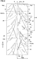
- FIG. 2 is a development view of a tread portion 2 of the tire 1, and FIG. 1 corresponds to the cross-section taken along line A-A of FIG. 2 .
- the tire 1 according to the embodiment may preferably be used for rear tires for sports driving, e.g., circuit racing.
- the normal state of the tire 1 is such that the tire 1 is mounted on a standard wheel rim with a standard pressure but is loaded with no tire load. Unless otherwise noted, dimensions of respective portions of the tire are values measured under the normal state.
- the standard wheel rim is a wheel rim officially approved for each tire by standards organizations on which the tire is based, wherein the standard wheel rim is the "standard rim” specified in JATMA, the "Design Rim” in TRA, and the “Measuring Rim” in ETRTO, for example.
- the standard pressure is a standard pressure officially approved for each tire by standards organizations on which the tire is based, wherein the standard pressure is the "maximum air pressure" in JATMA, the maximum pressure given in the "Tire Load Limits at Various Cold Inflation Pressures” table in TRA, and the “Inflation Pressure” in ETRTO, for example.
- the tire 1 under the normal state, includes the tread portion 2 that includes a first tread edge Te1, a second tread edge Te2, and a ground contact surface 2s between the first and second tread edges Te1 and Te2, wherein the ground contact surface 2s is curved in an arc shape manner to protrude radially outwardly.
- the tire 1 as such can obtain a sufficient ground contact surface area even when turning with large camber angles.
- the first tread edge Te1 and the second tread edge Te2 define axially both edges of the tread portion 2, and thus these edges can come into contact with the ground when turning with maximum camber angles.
- the tire 1 according to the embodiment for example, includes a carcass 6 and a belt 7. As these, conventional structures can be used.
- the tread portion 2 has a directional tread pattern having a designated rotation direction R.
- the rotation direction R for example, may be indicated on sidewall portions (illustrated in FIG. 1 ) by a mark or character. Note that the tire 1 according to the disclosure cannot be limited to such an aspect. Further, note that a forward side in the rotation direction R corresponds to upside of FIGS. 2 to 4 , and simply referred to as “forwardly” or “forward”. Note that a rearward side in the rotation direction R corresponds to downside of FIGS. 2 to 4 , and simply referred to as “rearward” or “rearwardly”.
- the tread portion 2 is provided with a plurality of first groove groups 10 and a plurality of second groove groups 20.
- the first groove groups 10, for example, are provided between the tire equator C and the first tread edge Te1. Note that one first groove group 10 in FIG. 2 is colored to help readers understanding.
- the second groove groups 20, for example, are provided between the tire equator C and the second tread edge Te2.
- the first groove groups 10 and the second groove groups 20 are arranged in a substantially symmetrical manner except that the first groove groups 10 are shifted in the tire circumferential direction from the second groove groups by a certain distance. Note detailed explanation for the second groove groups 20 is omitted since configuration of the first groove groups 10 can be applied to the second groove groups 20.
- Each of the first groove groups 10 includes a plurality of inclined main grooves 11 and a plurality of sub-grooves 12 smaller than the inclined main grooves 11 in groove width.
- groove widths W1 of the inclined main grooves 11 are preferably in a range of from 4.0% to 7.0% of a tread development half width TWh, for example.
- the tread development half width TWh is a distance from the tire equator C to the first tread edge Te1 measured along the ground contact surface 2s of the tread portion 2.
- groove depths of the inclined main grooves 11, for example, are of from 4 to 7 mm.
- groove width W2 of the sub-grooves 12, for example, are less than 2.0 mm.
- groove depths of the sub-grooves 12, for example, are less than 2.0 mm.
- the sub-grooves 12 can be useful to reduce in rigidity of portions therearound. By arranging the sub-grooves 12 on suitable locations, the difference in rigidity between portions around the inclined main grooves 11 and the remaining portions can be reduced, resulting in improving roll property.
- the inclined main grooves 11 includes an inner main groove 14.
- the inclined main grooves 11, in addition to the inner main groove 14, for example, include an outer main groove 15, a first short main groove 16, a second short main groove 17 and a third short main groove 18.
- the sub-grooves 12 include a first sub-groove 21.
- the sub-grooves 12 may further include a second sub-groove 22 and a third sub-groove 23.
- the inner main groove 14 extends from a first end 14a located on the tire equator side C to a second end 14b located on the first tread edge Te1 side with an inclination with respect to the tire circumferential direction, wherein no other grooves are provided between the first end 14a of the inner main groove 14 and the tire equator C.
- the inner main grooves 14 can be helpful to improve wet performance when not only straight traveling but also turning with small camber angles. Further, since no other grooves are provided between the tire equator C and the first end 14a of the inner main groove 14, sufficient tread rigidity around the tire equator C can be maintained to improve roll property so that riders feel linear response when the motorbike is leaned.
- the first sub-groove 21 extends from the inner main groove 14 toward the tire equator C with an opposite inclination direction to the inner main groove 14 with respect to the tire circumferential direction and terminating on the tire equator C side without being communicated with any other grooves.
- the first sub-groove 21 using its edges, generates friction force in a different direction to the inner main groove 14 on wet road conditions, resulting in better wet performance.
- the first sub-groove 21 since the first sub-groove 21 has a small groove width in relation to the inner main groove 14 and terminates without being communicated with any other grooves, it may not reduce in rigidity of a land portion around the tire equator C, thus maintaining excellent roll property.
- FIG. 3 illustrates an enlarged view of the inclined main grooves 11 included in one first groove group 10. Note that in FIG. 3 the sub-grooves are not illustrated. As illustrated in FIG. 3 , the inner main grooves 14 extends from the first end 14a forwardly in the rotation direction R to the first tread edge Te1 side. The inner main groove 14 with such an inclination can deliver excellent roll property. On the other hand, although the inner main groove 14 tends to send water to the tire equator C side on wet road traveling, wet performance can be improved due to the above-mentioned effect of the first sub-grooves 21.
- the inner main groove 14 is preferably inclined at an angle ⁇ 1 of from 15 to 30 degrees with respect to the tire circumferential direction.
- the first end 14a of the inner main groove 14 is located on the first tread edge Te1 side with respect to the tire equator C. That is, the inner main groove 14 does not traverse the tire equator C.
- a circumferentially and continuously extending plain region on which no other grooves are provided is formed on the tire equator C.
- the plain region as such can provide sufficient rigidity with a land portion around the tire equator C, improving initial roll property when the motorbike is leaned.
- an axial distance L1a from the first end 14a of the inner main groove 14 to the tire equator C is preferably in a range of from 0.03 to 0.08 times the tread development half width TWh (shown in FIG. 2 ).
- lengths and distances of the respective portions shall mean those which are measured along the ground contact surface 2s of the tread portion 2.
- an axial distance L1b from the second end 14b of the inner main groove 14 to the tire equator C is in a range of from 0.35 to 0.45 times the tread development half width TWh.
- the inner main groove 14 as such can exert excellent drainage performance while maintaining better roll property.
- the outer main grooves 15, for example, is located forward in the rotation direction R with respect to the inner main groove 14, and which are adjacent with each other.
- the outer main groove 15 is arranged in such a manner as to cross a region where the inner main groove 14 is expanded in a longitudinal direction thereof.
- the outer main groove 15, for example, is arranged on the first tread edge Te1 side with respect to the first sub-grooves 21 (shown in FIG. 2 ).
- the outer main groove 15, for example, is inclined in an opposite direction to the inner main groove 14 with respect to the tire circumferential direction. That is, the outer main grooves 15 extends from a first side 15a located on the tire equator C side to a second end 15b located on the first tread edge Te1 side toward rearwardly in the rotation direction R.
- an angle ⁇ 2 (shown in FIG. 2 ) of the outer main groove 15, for example, is in a range of from 40 to 50 degrees with respect to the tire circumferential direction. In some preferred embodiments, the angle ⁇ 2 of the outer main groove 15 is greater than the angle ⁇ 1 of the inner main groove 14.
- the outer main groove 15, for example, has a length shorter than that of the inner main groove 14.
- the outer main groove 15, for example, has a groove width which varies in the longitudinal direction, wherein the maximum groove width portion 15m is positioned on the tire equator C side with respect to a center location in the tire axial direction of the outer main groove 15. Further, in the outer main groove 15, the groove width decreases gradually from the maximum width portion 15m to the second end 15b.
- the first end 15a of the outer main groove 15, for example, is located on the tire equator C side with respect to the second end 14b of the inner main groove 14.
- the second end 15b of the outer main groove 15, for example, is located on the first tread edge Te1 side with respect to the second end 14b of the inner main groove 14.
- an axial first overlapped length L2 from the first end 15a of the outer main groove 15 to the second end 14b of the inner main groove 14, for example, is preferably in a range of from 0.10 to 0.25 times the tread development half width TWh.
- an axial distance L3 from the second end 15b of the outer main groove 15 to the tire equator C is in a range of from 0.50 to 0.65 times the tread development half width TWh.
- the second end 15b of the outer main groove 15, for example, is located forward in the rotation direction R with respect to the second end 14b of the inner main groove 14. That is, the outer main grooves 15 and the inner main groove 14 are preferably arranged with a circumferential gap therebetween so as not to overlap with each other in the tire circumferential direction.
- a circumferential first gap length L4 between the second end 15b of the outer main groove 15 and the second end 14b of the inner main groove 14, for example, is in a range of from 0.25 to 0.35 times a circumferential length L5 (shown in FIG. 2 ) of the inner main groove 14.
- Such a layout of the outer main groove 15 and the inner main groove 14, for example, may generate large traction when turning with large camber angles in which the second end 15b of the outer main groove 15 comes into contact with the ground.
- the first short main groove 16 for example, is located forward in the rotation direction R with respect to the outer main grooves 15, and which are adjacent with each other.
- the first short main groove 16, for example, has a length shorter than that of the outer main groove 15.
- the first short main groove 16 according to the embodiment, for example, is inclined in the same direction as the outer main groove 15.
- an angle ⁇ 3 (shown in FIG. 2 ) of the first short main groove 16 is in a range of from 45 to 60 degrees with respect to the tire circumferential direction.
- the first short main groove 16 for example, has a groove width which varies in the longitudinal direction, wherein the maximum groove width portion 16m is positioned on the tire equator C side with respect to a center location in the tire axial direction of the first short main groove 16. Further, in the first short main groove 16, the groove width decreases gradually from the maximum width portion 16m to the first tread edge Te1 side.
- a first end 16a of the first short main groove 16 located on the tire equator C side is located on the tire equator C side with respect to the second end 15b of the outer main groove 15.
- a second end 16b of the first short main groove 16 is located on the first tread edge Te1 side with respect to the second end 15b of the outer main groove 15.
- an axial second overlapped length L6 from the first end 16a of the first short main groove 16 to the second end 15b of the outer main groove 15, for example, is in a range of from 0.05 to 0.15 times the tread development half width TWh.
- the second overlapped length L6 is smaller than the first overlapped length L2 in order to further improve roll property so that response in which a rider leans with the motorbike to turn tends to increase proportionally according to an increase of the camber angle.
- an axial distance L7 from the second end 16b of the first short main groove 16 to the first tread edge Te1 is in a range of from 0.20 to 0.35 times the tread development half width TWh.
- the second end 16b of the first short main groove 16 is located forward in the rotation direction R with respect to the first end 15a of the outer main grooves 15. That is, the first short main groove 16 and the outer main grooves 15 are preferably arranged with a circumferential gap therebetween so as not to overlap with each other in the tire circumferential direction.
- a circumferential second gap length L8 between the second end 16b of the first short main groove 16 and the first end 15a of the outer main groove 15, for example is in a range of from 0.20 to 0.30 times the circumferential length L5 of the inner main groove 14.
- Such a layout of the first short main groove 16 and the outer main grooves 15, for example, may generate large traction when turning while maintaining better drainage performance.
- the second short main groove 17, for example, is located forward in the rotation direction R with respect to the first short main groove 16, and which are adjacent with each other.
- the second short main groove 17, for example, has a length shorter than that of the first short main groove 16.
- the second short main groove 17 according to the embodiment, for example, is inclined in the same direction as the first short main groove 16.
- an angle ⁇ 4 (shown in FIG. 2 ) of the second short main groove 17, for example, is in a range of from 60 to 70 degrees with respect to the tire circumferential direction.
- the maximum angle of the second short main groove 17 with respect to the tire circumferential direction is greater than the maximum angle of the first short main groove 16 with respect to the tire circumferential direction.
- the second short main groove 17 for example, has a groove width which varies in the longitudinal direction, wherein the maximum groove width portion 17m is positioned on the tire equator C side with respect to a center location in the tire axial direction of the second short main groove 17. Further, in the second short main groove 17, the groove width decreases gradually from the maximum width portion 17m to the first tread edge Te1 side.
- a first end 17a of the second short main groove 17 located on the tire equator C side is located on the tire equator C side with respect to the second end 16b of the first short main groove 16.
- a second end 17b of the second short main groove 17 on the first tread edge Te1 side is located on the first tread edge Te1 side with respect to the second end 16b of the first short main groove 16.
- an axial third overlapped length L9 from the first end 17a of the second short main groove 17 to the second end 16b of the first short main groove 16, for example, is in a range of from 0.05 to 0.10 times the tread development half width TWh.
- the third overlapped length L9 for example, is shorter than the second overlapped length L6 in order to improve wet performance and roll property in a well-balanced manner.
- an axial distance L10 from the second end 17b of the second short main groove 17 to the first tread edge Te1 is in a range of from 0.02 to 0.07 times the tread development half width TWh.
- the second end 17b of the second short main groove 17, for example, is located forward in the rotation direction R with respect to the first end 16a of the first short main groove 16. That is, the second short main groove 17 and the first short main groove 16 are preferably arranged with a circumferential gap therebetween so as not to overlap with each other in the tire circumferential direction.
- a circumferential third gap length L11 between the second end 17b of the second short main groove 17 and the first end 16a of the first short main groove 16, for example is in a range of from 0.30 to 0.45 times the circumferential length L5 of the inner main groove 14.
- the third gap length L11 for example, is longer than the second gap length L8.
- Such a layout of the second short main groove 17 and the first short main groove 16, for example, may generate large traction when turning with large camber angles in which the first tread edge Te1 comes into contact with the ground.
- the third short main groove 18, for example, is located forward in the rotation direction R with respect to the second end 14b of the inner main groove 14, and is located rearward in the rotation direction R with respect to the second end 15b of the outer main groove 15.
- the third short main groove 18, for example, is located on the first tread edge Te1 side with respect to the second end 16b of the first short main groove 16.
- a first end 18a of the third short main groove 18 on the tire equator C side is adjacent to the second end 15b the outer main grooves 15.
- the third short main groove 18, for example, is inclined in the same direction as the outer main grooves 15.
- an angle ⁇ 5 (shown in FIG. 2 ) of the third short main groove 18, for example, is in a range of from 55 to 65 degrees with respect to the tire circumferential direction.
- the maximum angle of the third short main groove 18 with respect to the tire circumferential direction is greater than the maximum angle of the outer main grooves 15 with respect to the tire circumferential direction.
- the first end 18a of the third short main groove 18 on the tire equator C side is located so as to cross a region in which the outer main groove 15 is expanded in a longitudinal direction thereof.
- third short main groove 18 makes up for a shortage of drainage of the outer main groove 15, resulting in better wet performance.
- the third short main groove 18, is located within an axial region of the second short main groove 17, i.e., located axially outwardly of the first end 17a but axially inwardly of the second end 17b.
- an axial length L12 of a second end 18b of the third short main groove 18 on the first tread edge Te1 side to the first tread edge Te1 is in a range of from 0.03 to 0.10 times the tread development half width TWh.
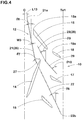
- FIG. 4 illustrates an enlarged view of the sub-grooves 12 included in one first groove group 10. Note that in FIG. 4 , some of the inclined main grooves 11 are not illustrated.
- the first sub-groove 21, for example includes a first portion 26 extending from a first end 21a located on the tire equator C side, and a second portion 27 connected to the first portion 26 and inclined at an angle ⁇ 7 greater than the angle ⁇ 6 of the first portion 26 with respect to the tire circumferential direction.
- the first portion 26 and the second portion 27 can maintain sufficient circumferential rigidity of a portion around the tire equator C, delivering better traction performance while maintaining the above effect.
- the angle ⁇ 6 of the first portion 26, for example, is in a range of from 5 to 15 degrees with respect to the tire circumferential direction.
- the angle ⁇ 7 of the second portion 27, for example, is in a range of from 20 to 35 degrees with respect to the tire circumferential direction.
- an axial distance L13 from the first end 21a of the first sub-groove 21 to the tire equator C is in a range of from 0.03 to 0.10 times the tread development half width TWh.
- the first end 21a of the first sub-grooves 21 is located forward in the rotation direction R with respect to the first end 15a of the outer main groove 15 to further improve wet performance.
- the first sub-groove 21 is in communication with the inner main groove 14 at a location which is on the first tread edge Te1 side with respect to the center location in the tire axial direction of the inner main groove 14.
- the first sub-groove 21 as such upon driving on wet road conditions, may suppress water in the inner main groove 41 to be sent toward the tire equator C, improving wet performance.
- the first sub-groove 21, for example, has a groove width W3 of from 0.3 to 1.5 mm.
- the first sub-groove 21, for example, has a groove depth of from 0.2 to 1.5 mm.
- the second sub-groove 22 and the third sub-groove 23 which are described later also have the same groove width and depth as the first sub-groove 21.
- the second sub-groove 22 is in communication with the inner main groove 14 as a location which is on the first tread edge Te1 side with respect to the center location in the tire axial direction of the inner main grooves 14.
- the second sub-groove 22 is arranged so as to be continuous smoothly to the first sub-groove 21 through the inner main groove 14.
- the above "be continuous smoothly” shall mean that when one of the sub-grooves is expanded in its longitudinal direction, the extended region is in communication with the end of the other one of the sub-grooves.
- an angle ⁇ 8 of the second sub-groove 22 is in a range of from 20 to 35 degrees with respect to the tire circumferential direction.
- the angle ⁇ 8 of the second sub-groove 22 is greater than the angle ⁇ 6 of the first portion 26 of the first sub-groove 21. That is, the first sub-groove 21 may include a portion having an angle with respect to the tire circumferential direction which is smaller than that of the second sub-groove 22.
- the second sub-groove 22 is inclined at the same angle with respect to the tire circumferential direction as the second portion 27 of the first sub-groove 21.
- the second sub-groove 22 extends between the first short main groove 16 and the second short main groove 17 which are adjacent each other, and terminates without reaching the first tread edge Te1.
- a second end 22b of the second sub-groove 22 on the first tread edge Te1 side is located on the first tread edge Te1 side with respect to the first end 18a of the third short main groove 18.
- a circumferential distance L14 (shown in FIG. 2 ) from the first end 21a of the first sub-groove 21 to the second end 22b of the second sub-groove 22 is longer than the circumferential length of the inner main groove L5.
- the distance L14 is in a range of from 2.0 to 3.0 times the length L5 of the inner main groove 14.
- the third sub-groove 23, for example, is arranged on the first tread edge Te1 side with respect to the first sub-groove 21 and the second sub-groove 22.
- the third sub-groove 23, for example, is inclined in the same direction as the first sub-groove 21.
- the third sub-groove 23 has both ends which terminate within the tread land portion to improve roll property and wet performance in a well-balanced manner upon turning with large camber angles.
- the third sub-groove 23 includes a portion extending in the same inclination direction as the first sub-groove 21 between the inner main groove 14 and the outer main groove 15.
- the third sub-groove 23 according to the embodiment, for example, includes an inner portion 28 on the tire equator C side, and an outer portion 29 on the first tread edge Te1 side.
- the inner portion 28, for example, extends between the inner main groove 14 and the outer main groove 15 and has an angle ⁇ 9 which is greater than the angle ⁇ 6 of the first portion 26 of the first sub-groove 21 with respect to the tire circumferential direction.
- the angle ⁇ 9 of the inner portion 28, for example is of from 25 to 35 degrees.
- the outer portion 29, for example, extends between the third short main groove 18 and the second short main groove 17 that is included in another first groove group 10 adjacent rearwardly in the rotation direction R, and is inclined with respect to the tire circumferential direction at an angle ⁇ 10 greater than the angle ⁇ 9 of the inner portion 28.
- the angle ⁇ 10 of the outer portion 29, for example, is greater than the angle ⁇ 8 of the second sub-groove 22.
- the angle ⁇ 10 of the outer portion 29, for example, is of from 35 to 50 degrees.
- the third sub-groove 23 preferably has a length which is longer than that of the outer main groove 15 but shorter than that of the inner main groove 14.
- a rider drove the motorcycle having each test tire for the rear wheel on a racing circuit with a dry road condition to evaluate initial roll property as well as middle and final roll property by the rider's sense.
- the initial roll property is roll property for camber angles in a range of from 0 to the angle of 30% of the maximum camber angle.
- the middle and final roll property is roll property for camber angles over 30% of the maximum camber angle.
- the test results are shown in Table 1 using a score system, wherein the score of comparative example (Ref.) is set to 100. The larger the value, the better the property is.
- a rider drove the motorcycle having each test tire for the rear wheel on a racing circuit with a wet road condition to evaluate wet performance by the rider's sense.
- the test results are shown in Table 1 using a score system, wherein the score of comparative example (Ref.) is set to 100. The larger the value, the better the wet performance is.
- Table 1 shows the test results. [Table 1] Ref. Ex. 1 Ex. 2 Ex. 3 Ex. 4 Ex. 5 Ex. 6 Ex. 7 Ex. 8 First sub-grooves none presence presence presence presence presence presence presence presence presence Second sub-grooves none presence none presence none presence presence presence presence presence Third sub-groove none presence none presence presence presence presence presence presence First sub-groove widths (mm) - 0.90 0.90 0.90 0.90 0.30 0.60 1.2 1.5 First sub-groove depths (mm) - 0.85 0.85 0.85 0.85 0.2 0.5 1.1 1.5
Landscapes
- Engineering & Computer Science (AREA)
- Mechanical Engineering (AREA)
- Tires In General (AREA)
Abstract
Description
- The present disclosure relates to a motorcycle tire.
- The following Patent document 1, for example, discloses a motorcycle tire having a tread portion which is provided with inner inclined main grooves around the tire equator. The above-mentioned inner inclined main grooves, for example, exert drainage performance when not only straight traveling but also turning with small camber angles.
- Unfortunately, it has been difficult to obtain sufficient improved wet performance by the inner inclined main grooves only. On the other hand, when additional grooves having larger widths and/or longer lengths are provided on the tread portion, tire response when a rider leans with the motorbike to turn tends to change suddenly, resulting in deterioration of roll property.
- [Patent document 1] Japanese Unexamined Patent Application Publication
2013-159207 - In view of the above problems in the conventional art, the present disclosure has a main object to provide a motorcycle tire capable of exerting an excellent wet performance while maintaining roll property.
- According to an aspect of the disclosure, a motorcycle tire includes a tread portion including a ground contact surface curved in an arc shape manner to protrude radially outwardly, a first tread edge and a tire equator, the tread portion provided with inclined main grooves arranged between the tire equator and the first tread edge and sub-grooves smaller than the inclined main grooves in groove width. The inclined main grooves include inner main grooves each extending from a first end located on the tire equator side to a second end located on the first tread edge side with an inclination with respect to a tire circumferential direction, wherein no other grooves are provided between the first end of each inner main groove and the tire equator. The sub-grooves include first sub-grooves extending from the inner main grooves toward the tire equator with an opposite inclination direction to the inner main grooves with respect to the tire circumferential direction and terminating on the tire equator side without being communicated with any other grooves.
- In another aspect of the disclosure, the tread portion has a designated rotation direction, and the inner main grooves each extend from the first end forwardly in the rotation direction toward the first tread edge.
- In another aspect of the disclosure, the sub-grooves may include second sub-grooves extending from the inner main grooves toward the first tread edge with a same inclination direction as the first sub-grooves with respect to the tire circumferential direction.
- In another aspect of the disclosure, the first sub-grooves each may include a portion having an angle with respect to the tire circumferential direction smaller than that of each of the second sub-grooves.
- In another aspect of the disclosure, the respective second sub-grooves may be continuous smoothly to the respective first sub-grooves through the inner main grooves.
- In another aspect of the disclosure, in a pair of first and second sub-grooves which are communicated with a same inner main groove, a circumferential distance from a first end of the first sub-groove located on the tire equator side to a second end of the second sub-groove located on the first tread edge side may be longer than a circumferential length of the inner main groove.
- In another aspect of the disclosure, groove widths of the first sub-grooves may be in a range of from 0.3 to 1.5 mm.
- In another aspect of the disclosure, groove depths of the first sub-grooves may be in a range of from 0.2 to 1.5 mm.
- In another aspect of the disclosure, the inclined main grooves may include outer main grooves arranged on the first tread edge side of the first sub-grooves and inclined in an opposite direction to the inner main grooves.
- In another aspect of the disclosure, the respective outer main grooves may overlap regions where the respective inner main grooves are expanded in a longitudinal direction thereof.
- In another aspect of the disclosure, the sub-grooves may include third sub-grooves each having a portion that is inclined in a same direction as the first sub-grooves in a region between one inner main groove and one adjacent outer main groove.
-
-
FIG. 1 is a cross-sectional view of a motorcycle tire according to an embodiment of the disclosure; -
FIG. 2 is a development view of a tread portion of the tire; -
FIG. 3 is a partial enlarged view for explaining inclined main grooves; and -
FIG. 4 is an enlarged view of sub-grooves ofFIG. 2 . - An embodiment of the present invention will be explained below with reference to the accompanying drawings.
-
FIG. 1 illustrates a cross-sectional view of a motorcycle tire (hereinafter, simply referred to as "tire") 1 under a normal state according to an embodiment of the disclosure.FIG. 2 is a development view of atread portion 2 of the tire 1, andFIG. 1 corresponds to the cross-section taken along line A-A ofFIG. 2 . - The tire 1 according to the embodiment, for example, may preferably be used for rear tires for sports driving, e.g., circuit racing.
- The normal state of the tire 1 is such that the tire 1 is mounted on a standard wheel rim with a standard pressure but is loaded with no tire load. Unless otherwise noted, dimensions of respective portions of the tire are values measured under the normal state.
- The standard wheel rim is a wheel rim officially approved for each tire by standards organizations on which the tire is based, wherein the standard wheel rim is the "standard rim" specified in JATMA, the "Design Rim" in TRA, and the "Measuring Rim" in ETRTO, for example.
- The standard pressure is a standard pressure officially approved for each tire by standards organizations on which the tire is based, wherein the standard pressure is the "maximum air pressure" in JATMA, the maximum pressure given in the "Tire Load Limits at Various Cold Inflation Pressures" table in TRA, and the "Inflation Pressure" in ETRTO, for example.
- As illustrated in
FIG. 1 , the tire 1 according to the embodiment, under the normal state, includes thetread portion 2 that includes a first tread edge Te1, a second tread edge Te2, and aground contact surface 2s between the first and second tread edges Te1 and Te2, wherein theground contact surface 2s is curved in an arc shape manner to protrude radially outwardly. The tire 1 as such can obtain a sufficient ground contact surface area even when turning with large camber angles. Note that the first tread edge Te1 and the second tread edge Te2 define axially both edges of thetread portion 2, and thus these edges can come into contact with the ground when turning with maximum camber angles. - The tire 1 according to the embodiment, for example, includes a
carcass 6 and abelt 7. As these, conventional structures can be used. - As illustrated in
FIG. 2 , thetread portion 2, for example, has a directional tread pattern having a designated rotation direction R. The rotation direction R, for example, may be indicated on sidewall portions (illustrated inFIG. 1 ) by a mark or character. Note that the tire 1 according to the disclosure cannot be limited to such an aspect. Further, note that a forward side in the rotation direction R corresponds to upside ofFIGS. 2 to 4 , and simply referred to as "forwardly" or "forward". Note that a rearward side in the rotation direction R corresponds to downside ofFIGS. 2 to 4 , and simply referred to as "rearward" or "rearwardly". - The
tread portion 2 is provided with a plurality offirst groove groups 10 and a plurality ofsecond groove groups 20. Thefirst groove groups 10, for example, are provided between the tire equator C and the first tread edge Te1. Note that onefirst groove group 10 inFIG. 2 is colored to help readers understanding. Thesecond groove groups 20, for example, are provided between the tire equator C and the second tread edge Te2. Thefirst groove groups 10 and thesecond groove groups 20 are arranged in a substantially symmetrical manner except that thefirst groove groups 10 are shifted in the tire circumferential direction from the second groove groups by a certain distance. Note detailed explanation for thesecond groove groups 20 is omitted since configuration of thefirst groove groups 10 can be applied to thesecond groove groups 20. - Each of the
first groove groups 10 includes a plurality of inclinedmain grooves 11 and a plurality ofsub-grooves 12 smaller than the inclinedmain grooves 11 in groove width. - It is not particularly limited, but groove widths W1 of the inclined
main grooves 11 are preferably in a range of from 4.0% to 7.0% of a tread development half width TWh, for example. As used herein, the tread development half width TWh is a distance from the tire equator C to the first tread edge Te1 measured along theground contact surface 2s of thetread portion 2. Preferably, groove depths of the inclinedmain grooves 11, for example, are of from 4 to 7 mm. - Preferably, groove width W2 of the
sub-grooves 12, for example, are less than 2.0 mm. Preferably, groove depths of thesub-grooves 12, for example, are less than 2.0 mm. Thesub-grooves 12 can be useful to reduce in rigidity of portions therearound. By arranging thesub-grooves 12 on suitable locations, the difference in rigidity between portions around the inclinedmain grooves 11 and the remaining portions can be reduced, resulting in improving roll property. - In each
first groove group 10, the inclinedmain grooves 11 includes an innermain groove 14. The inclinedmain grooves 11, in addition to the innermain groove 14, for example, include an outermain groove 15, a first shortmain groove 16, a second shortmain groove 17 and a third shortmain groove 18. In eachfirst groove group 10, thesub-grooves 12 include afirst sub-groove 21. In some preferred embodiments, the sub-grooves 12 may further include a second sub-groove 22 and athird sub-groove 23. - The inner
main groove 14 extends from afirst end 14a located on the tire equator side C to asecond end 14b located on the first tread edge Te1 side with an inclination with respect to the tire circumferential direction, wherein no other grooves are provided between thefirst end 14a of the innermain groove 14 and the tire equator C. - The inner
main grooves 14 can be helpful to improve wet performance when not only straight traveling but also turning with small camber angles. Further, since no other grooves are provided between the tire equator C and thefirst end 14a of the innermain groove 14, sufficient tread rigidity around the tire equator C can be maintained to improve roll property so that riders feel linear response when the motorbike is leaned. - The first sub-groove 21 extends from the inner
main groove 14 toward the tire equator C with an opposite inclination direction to the innermain groove 14 with respect to the tire circumferential direction and terminating on the tire equator C side without being communicated with any other grooves. - The first sub-groove 21, using its edges, generates friction force in a different direction to the inner
main groove 14 on wet road conditions, resulting in better wet performance. On the other hand, since the first sub-groove 21 has a small groove width in relation to the innermain groove 14 and terminates without being communicated with any other grooves, it may not reduce in rigidity of a land portion around the tire equator C, thus maintaining excellent roll property. -
FIG. 3 illustrates an enlarged view of the inclinedmain grooves 11 included in onefirst groove group 10. Note that inFIG. 3 the sub-grooves are not illustrated. As illustrated inFIG. 3 , the innermain grooves 14 extends from thefirst end 14a forwardly in the rotation direction R to the first tread edge Te1 side. The innermain groove 14 with such an inclination can deliver excellent roll property. On the other hand, although the innermain groove 14 tends to send water to the tire equator C side on wet road traveling, wet performance can be improved due to the above-mentioned effect of thefirst sub-grooves 21. - As illustrated in
FIG. 2 , in order to improve roll property and wet performance in a well-balanced manner, the innermain groove 14, for example, is preferably inclined at an angle θ1 of from 15 to 30 degrees with respect to the tire circumferential direction. - The
first end 14a of the innermain groove 14 is located on the first tread edge Te1 side with respect to the tire equator C. That is, the innermain groove 14 does not traverse the tire equator C. Thus, in this embodiment, on the tire equator C, a circumferentially and continuously extending plain region on which no other grooves are provided is formed. The plain region as such can provide sufficient rigidity with a land portion around the tire equator C, improving initial roll property when the motorbike is leaned. - As illustrated in
FIG. 3 , an axial distance L1a from thefirst end 14a of the innermain groove 14 to the tire equator C, for example, is preferably in a range of from 0.03 to 0.08 times the tread development half width TWh (shown inFIG. 2 ). Unless otherwise noted, lengths and distances of the respective portions shall mean those which are measured along theground contact surface 2s of thetread portion 2. - Preferably, an axial distance L1b from the
second end 14b of the innermain groove 14 to the tire equator C, for example, is in a range of from 0.35 to 0.45 times the tread development half width TWh. The innermain groove 14 as such can exert excellent drainage performance while maintaining better roll property. - The outer
main grooves 15, for example, is located forward in the rotation direction R with respect to the innermain groove 14, and which are adjacent with each other. In this embodiment, the outermain groove 15 is arranged in such a manner as to cross a region where the innermain groove 14 is expanded in a longitudinal direction thereof. Preferably, the outermain groove 15, for example, is arranged on the first tread edge Te1 side with respect to the first sub-grooves 21 (shown inFIG. 2 ). - The outer
main groove 15, for example, is inclined in an opposite direction to the innermain groove 14 with respect to the tire circumferential direction. That is, the outermain grooves 15 extends from afirst side 15a located on the tire equator C side to asecond end 15b located on the first tread edge Te1 side toward rearwardly in the rotation direction R. Preferably, an angle θ2 (shown inFIG. 2 ) of the outermain groove 15, for example, is in a range of from 40 to 50 degrees with respect to the tire circumferential direction. In some preferred embodiments, the angle θ2 of the outermain groove 15 is greater than the angle θ1 of the innermain groove 14. - The outer
main groove 15, for example, has a length shorter than that of the innermain groove 14. The outermain groove 15, for example, has a groove width which varies in the longitudinal direction, wherein the maximumgroove width portion 15m is positioned on the tire equator C side with respect to a center location in the tire axial direction of the outermain groove 15. Further, in the outermain groove 15, the groove width decreases gradually from themaximum width portion 15m to thesecond end 15b. Thus, response in which a rider leans with the motorbike to turn tends to increase proportionally according to an increase of the camber angle, resulting in excellent roll property. - Preferably, the
first end 15a of the outermain groove 15, for example, is located on the tire equator C side with respect to thesecond end 14b of the innermain groove 14. Preferably, thesecond end 15b of the outermain groove 15, for example, is located on the first tread edge Te1 side with respect to thesecond end 14b of the innermain groove 14. - In order to improve roll property and wet performance in a well-balanced manner, an axial first overlapped length L2 from the
first end 15a of the outermain groove 15 to thesecond end 14b of the innermain groove 14, for example, is preferably in a range of from 0.10 to 0.25 times the tread development half width TWh. - Preferably, an axial distance L3 from the
second end 15b of the outermain groove 15 to the tire equator C, for example, is in a range of from 0.50 to 0.65 times the tread development half width TWh. - Preferably, the
second end 15b of the outermain groove 15, for example, is located forward in the rotation direction R with respect to thesecond end 14b of the innermain groove 14. That is, the outermain grooves 15 and the innermain groove 14 are preferably arranged with a circumferential gap therebetween so as not to overlap with each other in the tire circumferential direction. Preferably, a circumferential first gap length L4 between thesecond end 15b of the outermain groove 15 and thesecond end 14b of the innermain groove 14, for example, is in a range of from 0.25 to 0.35 times a circumferential length L5 (shown inFIG. 2 ) of the innermain groove 14. Such a layout of the outermain groove 15 and the innermain groove 14, for example, may generate large traction when turning with large camber angles in which thesecond end 15b of the outermain groove 15 comes into contact with the ground. - The first short
main groove 16, for example, is located forward in the rotation direction R with respect to the outermain grooves 15, and which are adjacent with each other. The first shortmain groove 16, for example, has a length shorter than that of the outermain groove 15. The first shortmain groove 16 according to the embodiment, for example, is inclined in the same direction as the outermain groove 15. - Preferably, an angle θ3 (shown in
FIG. 2 ) of the first shortmain groove 16 is in a range of from 45 to 60 degrees with respect to the tire circumferential direction. - The first short
main groove 16, for example, has a groove width which varies in the longitudinal direction, wherein the maximumgroove width portion 16m is positioned on the tire equator C side with respect to a center location in the tire axial direction of the first shortmain groove 16. Further, in the first shortmain groove 16, the groove width decreases gradually from themaximum width portion 16m to the first tread edge Te1 side. - Preferably, a
first end 16a of the first shortmain groove 16 located on the tire equator C side, for example, is located on the tire equator C side with respect to thesecond end 15b of the outermain groove 15. Preferably, asecond end 16b of the first shortmain groove 16, for example, is located on the first tread edge Te1 side with respect to thesecond end 15b of the outermain groove 15. - Preferably, an axial second overlapped length L6 from the
first end 16a of the first shortmain groove 16 to thesecond end 15b of the outermain groove 15, for example, is in a range of from 0.05 to 0.15 times the tread development half width TWh. Preferably, the second overlapped length L6 is smaller than the first overlapped length L2 in order to further improve roll property so that response in which a rider leans with the motorbike to turn tends to increase proportionally according to an increase of the camber angle. - Preferably, an axial distance L7 from the
second end 16b of the first shortmain groove 16 to the first tread edge Te1, for example, is in a range of from 0.20 to 0.35 times the tread development half width TWh. - Preferably, the
second end 16b of the first shortmain groove 16, for example, is located forward in the rotation direction R with respect to thefirst end 15a of the outermain grooves 15. That is, the first shortmain groove 16 and the outermain grooves 15 are preferably arranged with a circumferential gap therebetween so as not to overlap with each other in the tire circumferential direction. Preferably, a circumferential second gap length L8 between thesecond end 16b of the first shortmain groove 16 and thefirst end 15a of the outermain groove 15, for example, is in a range of from 0.20 to 0.30 times the circumferential length L5 of the innermain groove 14. Such a layout of the first shortmain groove 16 and the outermain grooves 15, for example, may generate large traction when turning while maintaining better drainage performance. - The second short
main groove 17, for example, is located forward in the rotation direction R with respect to the first shortmain groove 16, and which are adjacent with each other. The second shortmain groove 17, for example, has a length shorter than that of the first shortmain groove 16. The second shortmain groove 17 according to the embodiment, for example, is inclined in the same direction as the first shortmain groove 16. - Preferably, an angle θ4 (shown in
FIG. 2 ) of the second shortmain groove 17, for example, is in a range of from 60 to 70 degrees with respect to the tire circumferential direction. In some preferred embodiments, the maximum angle of the second shortmain groove 17 with respect to the tire circumferential direction is greater than the maximum angle of the first shortmain groove 16 with respect to the tire circumferential direction. Thus, sufficient axial rigidity of a portion around the second shortmain groove 17 is maintained, resulting in large camber thrust. - The second short
main groove 17, for example, has a groove width which varies in the longitudinal direction, wherein the maximumgroove width portion 17m is positioned on the tire equator C side with respect to a center location in the tire axial direction of the second shortmain groove 17. Further, in the second shortmain groove 17, the groove width decreases gradually from themaximum width portion 17m to the first tread edge Te1 side. - Preferably, a
first end 17a of the second shortmain groove 17 located on the tire equator C side, for example, is located on the tire equator C side with respect to thesecond end 16b of the first shortmain groove 16. Preferably, asecond end 17b of the second shortmain groove 17 on the first tread edge Te1 side, for example, is located on the first tread edge Te1 side with respect to thesecond end 16b of the first shortmain groove 16. - Preferably, an axial third overlapped length L9 from the
first end 17a of the second shortmain groove 17 to thesecond end 16b of the first shortmain groove 16, for example, is in a range of from 0.05 to 0.10 times the tread development half width TWh. Preferably, the third overlapped length L9, for example, is shorter than the second overlapped length L6 in order to improve wet performance and roll property in a well-balanced manner. - Preferably, an axial distance L10 from the
second end 17b of the second shortmain groove 17 to the first tread edge Te1, for example, is in a range of from 0.02 to 0.07 times the tread development half width TWh. - Preferably, the
second end 17b of the second shortmain groove 17, for example, is located forward in the rotation direction R with respect to thefirst end 16a of the first shortmain groove 16. That is, the second shortmain groove 17 and the first shortmain groove 16 are preferably arranged with a circumferential gap therebetween so as not to overlap with each other in the tire circumferential direction. Preferably, a circumferential third gap length L11 between thesecond end 17b of the second shortmain groove 17 and thefirst end 16a of the first shortmain groove 16, for example, is in a range of from 0.30 to 0.45 times the circumferential length L5 of the innermain groove 14. Preferably, the third gap length L11, for example, is longer than the second gap length L8. Such a layout of the second shortmain groove 17 and the first shortmain groove 16, for example, may generate large traction when turning with large camber angles in which the first tread edge Te1 comes into contact with the ground. - The third short
main groove 18, for example, is located forward in the rotation direction R with respect to thesecond end 14b of the innermain groove 14, and is located rearward in the rotation direction R with respect to thesecond end 15b of the outermain groove 15. The third shortmain groove 18, for example, is located on the first tread edge Te1 side with respect to thesecond end 16b of the first shortmain groove 16. Thus, afirst end 18a of the third shortmain groove 18 on the tire equator C side is adjacent to thesecond end 15b the outermain grooves 15. - The third short
main groove 18, for example, is inclined in the same direction as the outermain grooves 15. Preferably, an angle θ5 (shown inFIG. 2 ) of the third shortmain groove 18, for example, is in a range of from 55 to 65 degrees with respect to the tire circumferential direction. In some preferred embodiments, the maximum angle of the third shortmain groove 18 with respect to the tire circumferential direction is greater than the maximum angle of the outermain grooves 15 with respect to the tire circumferential direction. Thus, sufficient axial rigidity of a portion around the third shortmain groove 18 can be maintained to generate large camber thrust. - Preferably, the
first end 18a of the third shortmain groove 18 on the tire equator C side, for example, is located so as to cross a region in which the outermain groove 15 is expanded in a longitudinal direction thereof. Thus, third shortmain groove 18 makes up for a shortage of drainage of the outermain groove 15, resulting in better wet performance. - Preferably, the third short
main groove 18, for example, is located within an axial region of the second shortmain groove 17, i.e., located axially outwardly of thefirst end 17a but axially inwardly of thesecond end 17b. - Preferably, an axial length L12 of a
second end 18b of the third shortmain groove 18 on the first tread edge Te1 side to the first tread edge Te1, for example, is in a range of from 0.03 to 0.10 times the tread development half width TWh. -
FIG. 4 illustrates an enlarged view of the sub-grooves 12 included in onefirst groove group 10. Note that inFIG. 4 , some of the inclinedmain grooves 11 are not illustrated. As illustrated inFIG. 4 , the first sub-groove 21, for example, includes afirst portion 26 extending from afirst end 21a located on the tire equator C side, and asecond portion 27 connected to thefirst portion 26 and inclined at an angle θ7 greater than the angle θ6 of thefirst portion 26 with respect to the tire circumferential direction. Thefirst portion 26 and thesecond portion 27 can maintain sufficient circumferential rigidity of a portion around the tire equator C, delivering better traction performance while maintaining the above effect. - Preferably, the angle θ6 of the
first portion 26, for example, is in a range of from 5 to 15 degrees with respect to the tire circumferential direction. Preferably, the angle θ7 of thesecond portion 27, for example, is in a range of from 20 to 35 degrees with respect to the tire circumferential direction. - Preferably, an axial distance L13 from the
first end 21a of the first sub-groove 21 to the tire equator C, for example, is in a range of from 0.03 to 0.10 times the tread development half width TWh. In this embodiment, thefirst end 21a of the first sub-grooves 21 is located forward in the rotation direction R with respect to thefirst end 15a of the outermain groove 15 to further improve wet performance. - Preferably, the first sub-groove 21, for example, is in communication with the inner
main groove 14 at a location which is on the first tread edge Te1 side with respect to the center location in the tire axial direction of the innermain groove 14. The first sub-groove 21 as such, upon driving on wet road conditions, may suppress water in the inner main groove 41 to be sent toward the tire equator C, improving wet performance. - Preferably, the first sub-groove 21, for example, has a groove width W3 of from 0.3 to 1.5 mm. Preferably, the first sub-groove 21, for example, has a groove depth of from 0.2 to 1.5 mm. Note that the second sub-groove 22 and the third sub-groove 23 which are described later also have the same groove width and depth as the
first sub-groove 21. - The second sub-groove 22, for example, extend from the inner
main grooves 14 to the first tread edge Te1 side with the same inclination direction as thefirst sub-grooves 21. - The second sub-groove 22, for example, is in communication with the inner
main groove 14 as a location which is on the first tread edge Te1 side with respect to the center location in the tire axial direction of the innermain grooves 14. In this embodiment, the second sub-groove 22 is arranged so as to be continuous smoothly to the first sub-groove 21 through the innermain groove 14. As used herein, the above "be continuous smoothly" shall mean that when one of the sub-grooves is expanded in its longitudinal direction, the extended region is in communication with the end of the other one of the sub-grooves. - Preferably, an angle θ8 of the second sub-groove 22, for example, is in a range of from 20 to 35 degrees with respect to the tire circumferential direction. Preferably, the angle θ8 of the second sub-groove 22 is greater than the angle θ6 of the
first portion 26 of thefirst sub-groove 21. That is, the first sub-groove 21 may include a portion having an angle with respect to the tire circumferential direction which is smaller than that of thesecond sub-groove 22. In some preferred embodiments, the second sub-groove 22 is inclined at the same angle with respect to the tire circumferential direction as thesecond portion 27 of thefirst sub-groove 21. - The second sub-groove 22, for example, extends between the first short
main groove 16 and the second shortmain groove 17 which are adjacent each other, and terminates without reaching the first tread edge Te1. In some preferred embodiments, asecond end 22b of the second sub-groove 22 on the first tread edge Te1 side, for example, is located on the first tread edge Te1 side with respect to thefirst end 18a of the third shortmain groove 18. - In order to further improve roll property and wet performance in a well-balanced manner, in a pair of first and second sub-grooves 21 and 22 which are communicated with a same inner
main groove 14, a circumferential distance L14 (shown inFIG. 2 ) from thefirst end 21a of the first sub-groove 21 to thesecond end 22b of the second sub-groove 22 is longer than the circumferential length of the inner main groove L5. Preferably, the distance L14 is in a range of from 2.0 to 3.0 times the length L5 of the innermain groove 14. - The third sub-groove 23, for example, is arranged on the first tread edge Te1 side with respect to the first sub-groove 21 and the
second sub-groove 22. The third sub-groove 23, for example, is inclined in the same direction as thefirst sub-groove 21. The third sub-groove 23 has both ends which terminate within the tread land portion to improve roll property and wet performance in a well-balanced manner upon turning with large camber angles. - The third sub-groove 23, for example, includes a portion extending in the same inclination direction as the first sub-groove 21 between the inner
main groove 14 and the outermain groove 15. The third sub-groove 23 according to the embodiment, for example, includes aninner portion 28 on the tire equator C side, and anouter portion 29 on the first tread edge Te1 side. Theinner portion 28, for example, extends between the innermain groove 14 and the outermain groove 15 and has an angle θ9 which is greater than the angle θ6 of thefirst portion 26 of the first sub-groove 21 with respect to the tire circumferential direction. Preferably, the angle θ9 of theinner portion 28, for example, is of from 25 to 35 degrees. - The
outer portion 29, for example, extends between the third shortmain groove 18 and the second shortmain groove 17 that is included in anotherfirst groove group 10 adjacent rearwardly in the rotation direction R, and is inclined with respect to the tire circumferential direction at an angle θ10 greater than the angle θ9 of theinner portion 28. The angle θ10 of theouter portion 29, for example, is greater than the angle θ8 of thesecond sub-groove 22. Specifically, the angle θ10 of theouter portion 29, for example, is of from 35 to 50 degrees. - In order to improve roll property further, the third sub-groove 23 preferably has a length which is longer than that of the outer
main groove 15 but shorter than that of the innermain groove 14. - While the particularly preferable embodiments in accordance with the present disclosure have been described in detail, the present disclosure is not limited to the illustrated embodiments but can be modified and carried out in various aspects.
- Motorcycle tires for rear wheels with a basic tread pattern as shown in
FIG. 1 andFIG. 2 were manufactured by way of trial based on the specification in Table 1. As for a comparative example (Ref.), a motorcycle tire which is not provided with any sub-grooves was also manufactured. The tread portion of the comparative example was a substantially same as the example tires as shown inFIG. 2 except for the above difference. Then, roll property and wet performance of each tire was evaluated. The common specification and the testing method for the test tires are as follows: - Test vehicle: motorcycle with a 1000 cc displacement
- Tire size: 180/55ZR17
- Rim size: MT5.50x17
- Tire inner pressure: 290 kPa
- A rider drove the motorcycle having each test tire for the rear wheel on a racing circuit with a dry road condition to evaluate initial roll property as well as middle and final roll property by the rider's sense. The initial roll property is roll property for camber angles in a range of from 0 to the angle of 30% of the maximum camber angle. The middle and final roll property is roll property for camber angles over 30% of the maximum camber angle. The test results are shown in Table 1 using a score system, wherein the score of comparative example (Ref.) is set to 100. The larger the value, the better the property is.
- A rider drove the motorcycle having each test tire for the rear wheel on a racing circuit with a wet road condition to evaluate wet performance by the rider's sense. The test results are shown in Table 1 using a score system, wherein the score of comparative example (Ref.) is set to 100. The larger the value, the better the wet performance is.
- Table 1 shows the test results.
[Table 1] Ref. Ex. 1 Ex. 2 Ex. 3 Ex. 4 Ex. 5 Ex. 6 Ex. 7 Ex. 8 First sub-grooves none presence presence presence presence presence presence presence presence Second sub-grooves none presence none presence none presence presence presence presence Third sub-groove none presence none none presence presence presence presence presence First sub-groove widths (mm) - 0.90 0.90 0.90 0.90 0.30 0.60 1.2 1.5 First sub-groove depths (mm) - 0.85 0.85 0.85 0.85 0.2 0.5 1.1 1.5 Initial roll property (score) 100 107 107 107 106 107 107 106 105 Middle/final roll property (score) 100 104 103 101 101 104 104 104 103 Wet performance (score) 100 110 106 108 108 105 108 110 111 - From the test results, it is confirmed that the example motorcycle tires improve wet performance while maintaining better roll property.
Claims (11)
- A motorcycle tire comprising:a tread portion comprising a ground contact surface curved in an arc shape manner to protrude radially outwardly, a first tread edge and a tire equator, the tread portion provided with inclined main grooves arranged between the tire equator and the first tread edge and sub-grooves smaller than the inclined main grooves in groove width;the inclined main grooves comprising inner main grooves each extending from a first end located on the tire equator side to a second end located on the first tread edge side with an inclination with respect to a tire circumferential direction, wherein no other grooves are provided between the first end of each inner main groove and the tire equator; andthe sub-grooves comprising first sub-grooves extending from the inner main grooves toward the tire equator with an opposite inclination direction to the inner main grooves with respect to the tire circumferential direction and terminating on the tire equator side without being communicated with any other grooves.
- The motorcycle tire according to claim 1, wherein
the tread portion has a designated rotation direction, and the inner main grooves each extend from the first end forwardly in the rotation direction toward the first tread edge. - The motorcycle tire according to claim 1 or 2, wherein
the sub-grooves comprise second sub-grooves extending from the inner main grooves toward the first tread edge with a same inclination direction as the first sub-grooves with respect to the tire circumferential direction. - The motorcycle tire according to claim 3, wherein
the first sub-grooves each comprise a portion having an angle with respect to the tire circumferential direction smaller than that of each of the second sub-grooves. - The motorcycle tire according to claim 3 or 4, wherein
the respective second sub-grooves are continuous smoothly to the respective first sub-grooves through the inner main grooves. - The motorcycle tire according to any one of claims 3 to 5, wherein
in a pair of first and second sub-grooves which are communicated with a same inner main groove, a circumferential distance from a first end of the first sub-groove located on the tire equator side to a second end of the second sub-groove located on the first tread edge side is longer than a circumferential length of the inner main groove. - The motorcycle tire according to any one of claims 1 to 6, wherein
groove widths of the first sub-grooves are in a range of from 0.3 to 1.5 mm. - The motorcycle tire according to any one of claims 1 to 7, wherein
groove depths of the first sub-grooves are in a range of from 0.2 to 1.5 mm. - The motorcycle tire according to any one of claims 1 to 8, wherein
the inclined main grooves comprise outer main grooves arranged on the first tread edge side of the first sub-grooves and inclined in an opposite direction to the inner main grooves. - The motorcycle tire according to claim 9, wherein
the respective outer main grooves overlap regions where the respective inner main grooves are expanded in a longitudinal direction thereof. - The motorcycle tire according to claim 9 or 10, wherein
the sub-grooves comprise third sub-grooves each having a portion that is inclined in a same direction as the first sub-grooves in a region between one inner main groove and one adjacent outer main groove.
Applications Claiming Priority (1)
| Application Number | Priority Date | Filing Date | Title |
|---|---|---|---|
| JP2017232468A JP6972986B2 (en) | 2017-12-04 | 2017-12-04 | Motorcycle tires |
Publications (2)
| Publication Number | Publication Date |
|---|---|
| EP3492282A1 true EP3492282A1 (en) | 2019-06-05 |
| EP3492282B1 EP3492282B1 (en) | 2020-09-30 |
Family
ID=63965133
Family Applications (1)
| Application Number | Title | Priority Date | Filing Date |
|---|---|---|---|
| EP18201512.3A Active EP3492282B1 (en) | 2017-12-04 | 2018-10-19 | Motorcycle tire |
Country Status (4)
| Country | Link |
|---|---|
| US (1) | US10981420B2 (en) |
| EP (1) | EP3492282B1 (en) |
| JP (1) | JP6972986B2 (en) |
| CN (1) | CN109866557B (en) |
Families Citing this family (3)
| Publication number | Priority date | Publication date | Assignee | Title |
|---|---|---|---|---|
| JP6851924B2 (en) * | 2017-07-14 | 2021-03-31 | 株式会社ブリヂストン | Pneumatic tires for motorcycles |
| CN114734759A (en) * | 2022-04-25 | 2022-07-12 | 建大橡胶(中国)有限公司 | High security electric motor car tire tread decorative pattern structure |
| EP4364971B1 (en) * | 2022-11-01 | 2025-12-03 | Sumitomo Rubber Industries, Ltd. | Two-wheel vehicle tire |
Citations (6)
| Publication number | Priority date | Publication date | Assignee | Title |
|---|---|---|---|---|
| GB2114069A (en) * | 1982-02-01 | 1983-08-17 | Avon Tyres Ltd | Motorcycle tyre tread |
| JPH0939516A (en) * | 1995-07-25 | 1997-02-10 | Bridgestone Corp | Pneumatic tire for two wheeler |
| JP2013159207A (en) | 2012-02-03 | 2013-08-19 | Sumitomo Rubber Ind Ltd | Motorcycle tire |
| CN205553802U (en) * | 2016-01-20 | 2016-09-07 | 厦门正新橡胶工业有限公司 | Pneumatic tire tread structure for two wheeler |
| WO2017077419A1 (en) * | 2015-11-04 | 2017-05-11 | Pirelli Tyre S.P.A. | Tyre for motorcycle wheels |
| CN107415596A (en) * | 2017-07-17 | 2017-12-01 | 正新(漳州)橡胶工业有限公司 | A kind of Pneumatic tire for two-wheeled vehicle tread pattern structure |
Family Cites Families (5)
| Publication number | Priority date | Publication date | Assignee | Title |
|---|---|---|---|---|
| JP5250021B2 (en) * | 2010-12-27 | 2013-07-31 | 住友ゴム工業株式会社 | Motorcycle tires |
| JP5444393B2 (en) * | 2012-03-01 | 2014-03-19 | 住友ゴム工業株式会社 | Motorcycle tires |
| JP5839594B2 (en) * | 2012-12-11 | 2016-01-06 | 住友ゴム工業株式会社 | Motorcycle tires |
| JP6581371B2 (en) * | 2015-03-20 | 2019-09-25 | 株式会社ブリヂストン | Motorcycle tires |
| JP6564303B2 (en) * | 2015-10-29 | 2019-08-21 | 株式会社ブリヂストン | Pneumatic tires for motorcycles |
-
2017
- 2017-12-04 JP JP2017232468A patent/JP6972986B2/en active Active
-
2018
- 2018-10-19 EP EP18201512.3A patent/EP3492282B1/en active Active
- 2018-11-02 CN CN201811299829.0A patent/CN109866557B/en active Active
- 2018-11-07 US US16/182,684 patent/US10981420B2/en active Active
Patent Citations (6)
| Publication number | Priority date | Publication date | Assignee | Title |
|---|---|---|---|---|
| GB2114069A (en) * | 1982-02-01 | 1983-08-17 | Avon Tyres Ltd | Motorcycle tyre tread |
| JPH0939516A (en) * | 1995-07-25 | 1997-02-10 | Bridgestone Corp | Pneumatic tire for two wheeler |
| JP2013159207A (en) | 2012-02-03 | 2013-08-19 | Sumitomo Rubber Ind Ltd | Motorcycle tire |
| WO2017077419A1 (en) * | 2015-11-04 | 2017-05-11 | Pirelli Tyre S.P.A. | Tyre for motorcycle wheels |
| CN205553802U (en) * | 2016-01-20 | 2016-09-07 | 厦门正新橡胶工业有限公司 | Pneumatic tire tread structure for two wheeler |
| CN107415596A (en) * | 2017-07-17 | 2017-12-01 | 正新(漳州)橡胶工业有限公司 | A kind of Pneumatic tire for two-wheeled vehicle tread pattern structure |
Also Published As
| Publication number | Publication date |
|---|---|
| US20190168543A1 (en) | 2019-06-06 |
| EP3492282B1 (en) | 2020-09-30 |
| JP6972986B2 (en) | 2021-11-24 |
| US10981420B2 (en) | 2021-04-20 |
| CN109866557B (en) | 2022-05-31 |
| JP2019098950A (en) | 2019-06-24 |
| CN109866557A (en) | 2019-06-11 |
Similar Documents
| Publication | Publication Date | Title |
|---|---|---|
| US9211768B2 (en) | Pneumatic tire | |
| EP3296127B1 (en) | Pneumatic tire | |
| EP3088211B1 (en) | Motorcycle pneumatic tire | |
| EP3189983B1 (en) | Pneumatic tire | |
| EP2620298B1 (en) | Pneumatic tire | |
| EP2732982B1 (en) | Pneumatic tire | |
| US9150056B2 (en) | Pneumatic tire | |
| US9096099B2 (en) | Pneumatic tire | |
| US10427465B2 (en) | Pneumatic tire | |
| EP3388255B1 (en) | Pneumatic tire | |
| US10836216B2 (en) | Tire | |
| EP2623338B1 (en) | Motorcycle tire | |
| EP3549794B1 (en) | Tyre | |
| US20240246366A1 (en) | Motorcycle tire set | |
| US11267289B2 (en) | Tire | |
| EP2851210A1 (en) | Motorcycle tire | |
| EP3492282B1 (en) | Motorcycle tire | |
| US10940722B2 (en) | Tire for a motorcycle | |
| CN109968910B (en) | Tyre for motorcycle | |
| EP3666553B1 (en) | Tyre for a motorcycle | |
| EP3040214B1 (en) | Tire for two-wheeled motor vehicle | |
| EP2821257B1 (en) | Pneumatic tire | |
| JP2022173900A (en) | tire |
Legal Events
| Date | Code | Title | Description |
|---|---|---|---|
| PUAI | Public reference made under article 153(3) epc to a published international application that has entered the european phase |
Free format text: ORIGINAL CODE: 0009012 |
|
| STAA | Information on the status of an ep patent application or granted ep patent |
Free format text: STATUS: THE APPLICATION HAS BEEN PUBLISHED |
|
| AK | Designated contracting states |
Kind code of ref document: A1 Designated state(s): AL AT BE BG CH CY CZ DE DK EE ES FI FR GB GR HR HU IE IS IT LI LT LU LV MC MK MT NL NO PL PT RO RS SE SI SK SM TR |
|
| AX | Request for extension of the european patent |
Extension state: BA ME |
|
| STAA | Information on the status of an ep patent application or granted ep patent |
Free format text: STATUS: REQUEST FOR EXAMINATION WAS MADE |
|
| 17P | Request for examination filed |
Effective date: 20190827 |
|
| RBV | Designated contracting states (corrected) |
Designated state(s): AL AT BE BG CH CY CZ DE DK EE ES FI FR GB GR HR HU IE IS IT LI LT LU LV MC MK MT NL NO PL PT RO RS SE SI SK SM TR |
|
| STAA | Information on the status of an ep patent application or granted ep patent |
Free format text: STATUS: EXAMINATION IS IN PROGRESS |
|
| 17Q | First examination report despatched |
Effective date: 20200203 |
|
| GRAP | Despatch of communication of intention to grant a patent |
Free format text: ORIGINAL CODE: EPIDOSNIGR1 |
|
| STAA | Information on the status of an ep patent application or granted ep patent |
Free format text: STATUS: GRANT OF PATENT IS INTENDED |
|
| INTG | Intention to grant announced |
Effective date: 20200709 |
|
| GRAS | Grant fee paid |
Free format text: ORIGINAL CODE: EPIDOSNIGR3 |
|
| GRAA | (expected) grant |
Free format text: ORIGINAL CODE: 0009210 |
|
| STAA | Information on the status of an ep patent application or granted ep patent |
Free format text: STATUS: THE PATENT HAS BEEN GRANTED |
|
| AK | Designated contracting states |
Kind code of ref document: B1 Designated state(s): AL AT BE BG CH CY CZ DE DK EE ES FI FR GB GR HR HU IE IS IT LI LT LU LV MC MK MT NL NO PL PT RO RS SE SI SK SM TR |
|
| REG | Reference to a national code |
Ref country code: CH Ref legal event code: EP Ref country code: GB Ref legal event code: FG4D |
|
| REG | Reference to a national code |
Ref country code: DE Ref legal event code: R096 Ref document number: 602018008269 Country of ref document: DE Ref country code: AT Ref legal event code: REF Ref document number: 1318435 Country of ref document: AT Kind code of ref document: T Effective date: 20201015 |
|
| REG | Reference to a national code |
Ref country code: IE Ref legal event code: FG4D |
|
| PG25 | Lapsed in a contracting state [announced via postgrant information from national office to epo] |
Ref country code: HR Free format text: LAPSE BECAUSE OF FAILURE TO SUBMIT A TRANSLATION OF THE DESCRIPTION OR TO PAY THE FEE WITHIN THE PRESCRIBED TIME-LIMIT Effective date: 20200930 Ref country code: BG Free format text: LAPSE BECAUSE OF FAILURE TO SUBMIT A TRANSLATION OF THE DESCRIPTION OR TO PAY THE FEE WITHIN THE PRESCRIBED TIME-LIMIT Effective date: 20201230 Ref country code: SE Free format text: LAPSE BECAUSE OF FAILURE TO SUBMIT A TRANSLATION OF THE DESCRIPTION OR TO PAY THE FEE WITHIN THE PRESCRIBED TIME-LIMIT Effective date: 20200930 Ref country code: FI Free format text: LAPSE BECAUSE OF FAILURE TO SUBMIT A TRANSLATION OF THE DESCRIPTION OR TO PAY THE FEE WITHIN THE PRESCRIBED TIME-LIMIT Effective date: 20200930 Ref country code: NO Free format text: LAPSE BECAUSE OF FAILURE TO SUBMIT A TRANSLATION OF THE DESCRIPTION OR TO PAY THE FEE WITHIN THE PRESCRIBED TIME-LIMIT Effective date: 20201230 Ref country code: GR Free format text: LAPSE BECAUSE OF FAILURE TO SUBMIT A TRANSLATION OF THE DESCRIPTION OR TO PAY THE FEE WITHIN THE PRESCRIBED TIME-LIMIT Effective date: 20201231 |
|
| REG | Reference to a national code |
Ref country code: AT Ref legal event code: MK05 Ref document number: 1318435 Country of ref document: AT Kind code of ref document: T Effective date: 20200930 |
|
| PG25 | Lapsed in a contracting state [announced via postgrant information from national office to epo] |
Ref country code: RS Free format text: LAPSE BECAUSE OF FAILURE TO SUBMIT A TRANSLATION OF THE DESCRIPTION OR TO PAY THE FEE WITHIN THE PRESCRIBED TIME-LIMIT Effective date: 20200930 Ref country code: LV Free format text: LAPSE BECAUSE OF FAILURE TO SUBMIT A TRANSLATION OF THE DESCRIPTION OR TO PAY THE FEE WITHIN THE PRESCRIBED TIME-LIMIT Effective date: 20200930 |
|
| REG | Reference to a national code |
Ref country code: NL Ref legal event code: MP Effective date: 20200930 |
|
| REG | Reference to a national code |
Ref country code: LT Ref legal event code: MG4D |
|
| PG25 | Lapsed in a contracting state [announced via postgrant information from national office to epo] |
Ref country code: EE Free format text: LAPSE BECAUSE OF FAILURE TO SUBMIT A TRANSLATION OF THE DESCRIPTION OR TO PAY THE FEE WITHIN THE PRESCRIBED TIME-LIMIT Effective date: 20200930 Ref country code: RO Free format text: LAPSE BECAUSE OF FAILURE TO SUBMIT A TRANSLATION OF THE DESCRIPTION OR TO PAY THE FEE WITHIN THE PRESCRIBED TIME-LIMIT Effective date: 20200930 Ref country code: PT Free format text: LAPSE BECAUSE OF FAILURE TO SUBMIT A TRANSLATION OF THE DESCRIPTION OR TO PAY THE FEE WITHIN THE PRESCRIBED TIME-LIMIT Effective date: 20210201 Ref country code: CZ Free format text: LAPSE BECAUSE OF FAILURE TO SUBMIT A TRANSLATION OF THE DESCRIPTION OR TO PAY THE FEE WITHIN THE PRESCRIBED TIME-LIMIT Effective date: 20200930 Ref country code: LT Free format text: LAPSE BECAUSE OF FAILURE TO SUBMIT A TRANSLATION OF THE DESCRIPTION OR TO PAY THE FEE WITHIN THE PRESCRIBED TIME-LIMIT Effective date: 20200930 Ref country code: SM Free format text: LAPSE BECAUSE OF FAILURE TO SUBMIT A TRANSLATION OF THE DESCRIPTION OR TO PAY THE FEE WITHIN THE PRESCRIBED TIME-LIMIT Effective date: 20200930 |
|
| PG25 | Lapsed in a contracting state [announced via postgrant information from national office to epo] |
Ref country code: AL Free format text: LAPSE BECAUSE OF FAILURE TO SUBMIT A TRANSLATION OF THE DESCRIPTION OR TO PAY THE FEE WITHIN THE PRESCRIBED TIME-LIMIT Effective date: 20200930 Ref country code: AT Free format text: LAPSE BECAUSE OF FAILURE TO SUBMIT A TRANSLATION OF THE DESCRIPTION OR TO PAY THE FEE WITHIN THE PRESCRIBED TIME-LIMIT Effective date: 20200930 Ref country code: ES Free format text: LAPSE BECAUSE OF FAILURE TO SUBMIT A TRANSLATION OF THE DESCRIPTION OR TO PAY THE FEE WITHIN THE PRESCRIBED TIME-LIMIT Effective date: 20200930 Ref country code: PL Free format text: LAPSE BECAUSE OF FAILURE TO SUBMIT A TRANSLATION OF THE DESCRIPTION OR TO PAY THE FEE WITHIN THE PRESCRIBED TIME-LIMIT Effective date: 20200930 Ref country code: IS Free format text: LAPSE BECAUSE OF FAILURE TO SUBMIT A TRANSLATION OF THE DESCRIPTION OR TO PAY THE FEE WITHIN THE PRESCRIBED TIME-LIMIT Effective date: 20210130 |
|
| PG25 | Lapsed in a contracting state [announced via postgrant information from national office to epo] |
Ref country code: MC Free format text: LAPSE BECAUSE OF FAILURE TO SUBMIT A TRANSLATION OF THE DESCRIPTION OR TO PAY THE FEE WITHIN THE PRESCRIBED TIME-LIMIT Effective date: 20200930 Ref country code: NL Free format text: LAPSE BECAUSE OF FAILURE TO SUBMIT A TRANSLATION OF THE DESCRIPTION OR TO PAY THE FEE WITHIN THE PRESCRIBED TIME-LIMIT Effective date: 20200930 Ref country code: LU Free format text: LAPSE BECAUSE OF NON-PAYMENT OF DUE FEES Effective date: 20201019 Ref country code: SK Free format text: LAPSE BECAUSE OF FAILURE TO SUBMIT A TRANSLATION OF THE DESCRIPTION OR TO PAY THE FEE WITHIN THE PRESCRIBED TIME-LIMIT Effective date: 20200930 |
|
| REG | Reference to a national code |
Ref country code: DE Ref legal event code: R097 Ref document number: 602018008269 Country of ref document: DE |
|
| REG | Reference to a national code |
Ref country code: BE Ref legal event code: MM Effective date: 20201031 |
|
| PLBE | No opposition filed within time limit |
Free format text: ORIGINAL CODE: 0009261 |
|
| STAA | Information on the status of an ep patent application or granted ep patent |
Free format text: STATUS: NO OPPOSITION FILED WITHIN TIME LIMIT |
|
| PG25 | Lapsed in a contracting state [announced via postgrant information from national office to epo] |
Ref country code: DK Free format text: LAPSE BECAUSE OF FAILURE TO SUBMIT A TRANSLATION OF THE DESCRIPTION OR TO PAY THE FEE WITHIN THE PRESCRIBED TIME-LIMIT Effective date: 20200930 Ref country code: BE Free format text: LAPSE BECAUSE OF NON-PAYMENT OF DUE FEES Effective date: 20201031 |
|
| 26N | No opposition filed |
Effective date: 20210701 |
|
| PG25 | Lapsed in a contracting state [announced via postgrant information from national office to epo] |
Ref country code: IE Free format text: LAPSE BECAUSE OF NON-PAYMENT OF DUE FEES Effective date: 20201019 Ref country code: IT Free format text: LAPSE BECAUSE OF FAILURE TO SUBMIT A TRANSLATION OF THE DESCRIPTION OR TO PAY THE FEE WITHIN THE PRESCRIBED TIME-LIMIT Effective date: 20200930 |
|
| PG25 | Lapsed in a contracting state [announced via postgrant information from national office to epo] |
Ref country code: SI Free format text: LAPSE BECAUSE OF FAILURE TO SUBMIT A TRANSLATION OF THE DESCRIPTION OR TO PAY THE FEE WITHIN THE PRESCRIBED TIME-LIMIT Effective date: 20200930 |
|
| REG | Reference to a national code |
Ref country code: CH Ref legal event code: PL |
|
| PG25 | Lapsed in a contracting state [announced via postgrant information from national office to epo] |
Ref country code: IS Free format text: LAPSE BECAUSE OF FAILURE TO SUBMIT A TRANSLATION OF THE DESCRIPTION OR TO PAY THE FEE WITHIN THE PRESCRIBED TIME-LIMIT Effective date: 20210130 Ref country code: TR Free format text: LAPSE BECAUSE OF FAILURE TO SUBMIT A TRANSLATION OF THE DESCRIPTION OR TO PAY THE FEE WITHIN THE PRESCRIBED TIME-LIMIT Effective date: 20200930 Ref country code: MT Free format text: LAPSE BECAUSE OF FAILURE TO SUBMIT A TRANSLATION OF THE DESCRIPTION OR TO PAY THE FEE WITHIN THE PRESCRIBED TIME-LIMIT Effective date: 20200930 Ref country code: CY Free format text: LAPSE BECAUSE OF FAILURE TO SUBMIT A TRANSLATION OF THE DESCRIPTION OR TO PAY THE FEE WITHIN THE PRESCRIBED TIME-LIMIT Effective date: 20200930 |
|
| PG25 | Lapsed in a contracting state [announced via postgrant information from national office to epo] |
Ref country code: MK Free format text: LAPSE BECAUSE OF FAILURE TO SUBMIT A TRANSLATION OF THE DESCRIPTION OR TO PAY THE FEE WITHIN THE PRESCRIBED TIME-LIMIT Effective date: 20200930 |
|
| PG25 | Lapsed in a contracting state [announced via postgrant information from national office to epo] |
Ref country code: LI Free format text: LAPSE BECAUSE OF NON-PAYMENT OF DUE FEES Effective date: 20211031 Ref country code: CH Free format text: LAPSE BECAUSE OF NON-PAYMENT OF DUE FEES Effective date: 20211031 |
|
| P01 | Opt-out of the competence of the unified patent court (upc) registered |
Effective date: 20230510 |
|
| GBPC | Gb: european patent ceased through non-payment of renewal fee |
Effective date: 20221019 |
|
| PG25 | Lapsed in a contracting state [announced via postgrant information from national office to epo] |
Ref country code: GB Free format text: LAPSE BECAUSE OF NON-PAYMENT OF DUE FEES Effective date: 20221019 |
|
| PGFP | Annual fee paid to national office [announced via postgrant information from national office to epo] |
Ref country code: FR Payment date: 20250908 Year of fee payment: 8 |
|
| PGFP | Annual fee paid to national office [announced via postgrant information from national office to epo] |
Ref country code: DE Payment date: 20250902 Year of fee payment: 8 |