EP3492250A1 - System and method for applying vacuum pressure to composite parts - Google Patents
System and method for applying vacuum pressure to composite parts Download PDFInfo
- Publication number
- EP3492250A1 EP3492250A1 EP18193041.3A EP18193041A EP3492250A1 EP 3492250 A1 EP3492250 A1 EP 3492250A1 EP 18193041 A EP18193041 A EP 18193041A EP 3492250 A1 EP3492250 A1 EP 3492250A1
- Authority
- EP
- European Patent Office
- Prior art keywords
- vacuum
- probe
- sharpened body
- valve element
- recited
- Prior art date
- Legal status (The legal status is an assumption and is not a legal conclusion. Google has not performed a legal analysis and makes no representation as to the accuracy of the status listed.)
- Granted
Links
Images


Classifications
-
- B—PERFORMING OPERATIONS; TRANSPORTING
- B29—WORKING OF PLASTICS; WORKING OF SUBSTANCES IN A PLASTIC STATE IN GENERAL
- B29C—SHAPING OR JOINING OF PLASTICS; SHAPING OF MATERIAL IN A PLASTIC STATE, NOT OTHERWISE PROVIDED FOR; AFTER-TREATMENT OF THE SHAPED PRODUCTS, e.g. REPAIRING
- B29C43/00—Compression moulding, i.e. applying external pressure to flow the moulding material; Apparatus therefor
- B29C43/32—Component parts, details or accessories; Auxiliary operations
- B29C43/36—Moulds for making articles of definite length, i.e. discrete articles
- B29C43/3642—Bags, bleeder sheets or cauls for isostatic pressing
-
- B—PERFORMING OPERATIONS; TRANSPORTING
- B29—WORKING OF PLASTICS; WORKING OF SUBSTANCES IN A PLASTIC STATE IN GENERAL
- B29C—SHAPING OR JOINING OF PLASTICS; SHAPING OF MATERIAL IN A PLASTIC STATE, NOT OTHERWISE PROVIDED FOR; AFTER-TREATMENT OF THE SHAPED PRODUCTS, e.g. REPAIRING
- B29C43/00—Compression moulding, i.e. applying external pressure to flow the moulding material; Apparatus therefor
- B29C43/32—Component parts, details or accessories; Auxiliary operations
- B29C43/36—Moulds for making articles of definite length, i.e. discrete articles
- B29C43/3607—Moulds for making articles of definite length, i.e. discrete articles with sealing means or the like
-
- B—PERFORMING OPERATIONS; TRANSPORTING
- B29—WORKING OF PLASTICS; WORKING OF SUBSTANCES IN A PLASTIC STATE IN GENERAL
- B29C—SHAPING OR JOINING OF PLASTICS; SHAPING OF MATERIAL IN A PLASTIC STATE, NOT OTHERWISE PROVIDED FOR; AFTER-TREATMENT OF THE SHAPED PRODUCTS, e.g. REPAIRING
- B29C70/00—Shaping composites, i.e. plastics material comprising reinforcements, fillers or preformed parts, e.g. inserts
- B29C70/04—Shaping composites, i.e. plastics material comprising reinforcements, fillers or preformed parts, e.g. inserts comprising reinforcements only, e.g. self-reinforcing plastics
- B29C70/28—Shaping operations therefor
- B29C70/40—Shaping or impregnating by compression not applied
- B29C70/42—Shaping or impregnating by compression not applied for producing articles of definite length, i.e. discrete articles
- B29C70/44—Shaping or impregnating by compression not applied for producing articles of definite length, i.e. discrete articles using isostatic pressure, e.g. pressure difference-moulding, vacuum bag-moulding, autoclave-moulding or expanding rubber-moulding
-
- B—PERFORMING OPERATIONS; TRANSPORTING
- B29—WORKING OF PLASTICS; WORKING OF SUBSTANCES IN A PLASTIC STATE IN GENERAL
- B29C—SHAPING OR JOINING OF PLASTICS; SHAPING OF MATERIAL IN A PLASTIC STATE, NOT OTHERWISE PROVIDED FOR; AFTER-TREATMENT OF THE SHAPED PRODUCTS, e.g. REPAIRING
- B29C70/00—Shaping composites, i.e. plastics material comprising reinforcements, fillers or preformed parts, e.g. inserts
- B29C70/04—Shaping composites, i.e. plastics material comprising reinforcements, fillers or preformed parts, e.g. inserts comprising reinforcements only, e.g. self-reinforcing plastics
- B29C70/28—Shaping operations therefor
- B29C70/40—Shaping or impregnating by compression not applied
- B29C70/42—Shaping or impregnating by compression not applied for producing articles of definite length, i.e. discrete articles
- B29C70/44—Shaping or impregnating by compression not applied for producing articles of definite length, i.e. discrete articles using isostatic pressure, e.g. pressure difference-moulding, vacuum bag-moulding, autoclave-moulding or expanding rubber-moulding
- B29C70/443—Shaping or impregnating by compression not applied for producing articles of definite length, i.e. discrete articles using isostatic pressure, e.g. pressure difference-moulding, vacuum bag-moulding, autoclave-moulding or expanding rubber-moulding and impregnating by vacuum or injection
-
- B—PERFORMING OPERATIONS; TRANSPORTING
- B29—WORKING OF PLASTICS; WORKING OF SUBSTANCES IN A PLASTIC STATE IN GENERAL
- B29C—SHAPING OR JOINING OF PLASTICS; SHAPING OF MATERIAL IN A PLASTIC STATE, NOT OTHERWISE PROVIDED FOR; AFTER-TREATMENT OF THE SHAPED PRODUCTS, e.g. REPAIRING
- B29C70/00—Shaping composites, i.e. plastics material comprising reinforcements, fillers or preformed parts, e.g. inserts
- B29C70/04—Shaping composites, i.e. plastics material comprising reinforcements, fillers or preformed parts, e.g. inserts comprising reinforcements only, e.g. self-reinforcing plastics
- B29C70/28—Shaping operations therefor
- B29C70/54—Component parts, details or accessories; Auxiliary operations, e.g. feeding or storage of prepregs or SMC after impregnation or during ageing
- B29C70/544—Details of vacuum bags, e.g. materials or shape
-
- B—PERFORMING OPERATIONS; TRANSPORTING
- B32—LAYERED PRODUCTS
- B32B—LAYERED PRODUCTS, i.e. PRODUCTS BUILT-UP OF STRATA OF FLAT OR NON-FLAT, e.g. CELLULAR OR HONEYCOMB, FORM
- B32B37/00—Methods or apparatus for laminating, e.g. by curing or by ultrasonic bonding
- B32B37/10—Methods or apparatus for laminating, e.g. by curing or by ultrasonic bonding characterised by the pressing technique, e.g. using action of vacuum or fluid pressure
- B32B37/1009—Methods or apparatus for laminating, e.g. by curing or by ultrasonic bonding characterised by the pressing technique, e.g. using action of vacuum or fluid pressure using vacuum and fluid pressure
-
- F—MECHANICAL ENGINEERING; LIGHTING; HEATING; WEAPONS; BLASTING
- F16—ENGINEERING ELEMENTS AND UNITS; GENERAL MEASURES FOR PRODUCING AND MAINTAINING EFFECTIVE FUNCTIONING OF MACHINES OR INSTALLATIONS; THERMAL INSULATION IN GENERAL
- F16K—VALVES; TAPS; COCKS; ACTUATING-FLOATS; DEVICES FOR VENTING OR AERATING
- F16K15/00—Check valves
- F16K15/02—Check valves with guided rigid valve members
- F16K15/06—Check valves with guided rigid valve members with guided stems
- F16K15/063—Check valves with guided rigid valve members with guided stems the valve being loaded by a spring
-
- F—MECHANICAL ENGINEERING; LIGHTING; HEATING; WEAPONS; BLASTING
- F16—ENGINEERING ELEMENTS AND UNITS; GENERAL MEASURES FOR PRODUCING AND MAINTAINING EFFECTIVE FUNCTIONING OF MACHINES OR INSTALLATIONS; THERMAL INSULATION IN GENERAL
- F16K—VALVES; TAPS; COCKS; ACTUATING-FLOATS; DEVICES FOR VENTING OR AERATING
- F16K15/00—Check valves
- F16K15/02—Check valves with guided rigid valve members
- F16K15/06—Check valves with guided rigid valve members with guided stems
- F16K15/063—Check valves with guided rigid valve members with guided stems the valve being loaded by a spring
- F16K15/066—Check valves with guided rigid valve members with guided stems the valve being loaded by a spring with a plurality of valve members
-
- F—MECHANICAL ENGINEERING; LIGHTING; HEATING; WEAPONS; BLASTING
- F16—ENGINEERING ELEMENTS AND UNITS; GENERAL MEASURES FOR PRODUCING AND MAINTAINING EFFECTIVE FUNCTIONING OF MACHINES OR INSTALLATIONS; THERMAL INSULATION IN GENERAL
- F16L—PIPES; JOINTS OR FITTINGS FOR PIPES; SUPPORTS FOR PIPES, CABLES OR PROTECTIVE TUBING; MEANS FOR THERMAL INSULATION IN GENERAL
- F16L37/00—Couplings of the quick-acting type
- F16L37/08—Couplings of the quick-acting type in which the connection between abutting or axially overlapping ends is maintained by locking members
- F16L37/084—Couplings of the quick-acting type in which the connection between abutting or axially overlapping ends is maintained by locking members combined with automatic locking
- F16L37/098—Couplings of the quick-acting type in which the connection between abutting or axially overlapping ends is maintained by locking members combined with automatic locking by means of flexible hooks
- F16L37/0982—Couplings of the quick-acting type in which the connection between abutting or axially overlapping ends is maintained by locking members combined with automatic locking by means of flexible hooks with a separate member for releasing the coupling
-
- B—PERFORMING OPERATIONS; TRANSPORTING
- B29—WORKING OF PLASTICS; WORKING OF SUBSTANCES IN A PLASTIC STATE IN GENERAL
- B29C—SHAPING OR JOINING OF PLASTICS; SHAPING OF MATERIAL IN A PLASTIC STATE, NOT OTHERWISE PROVIDED FOR; AFTER-TREATMENT OF THE SHAPED PRODUCTS, e.g. REPAIRING
- B29C43/00—Compression moulding, i.e. applying external pressure to flow the moulding material; Apparatus therefor
- B29C43/32—Component parts, details or accessories; Auxiliary operations
- B29C43/36—Moulds for making articles of definite length, i.e. discrete articles
- B29C43/3642—Bags, bleeder sheets or cauls for isostatic pressing
- B29C2043/3644—Vacuum bags; Details thereof, e.g. fixing or clamping
-
- B—PERFORMING OPERATIONS; TRANSPORTING
- B32—LAYERED PRODUCTS
- B32B—LAYERED PRODUCTS, i.e. PRODUCTS BUILT-UP OF STRATA OF FLAT OR NON-FLAT, e.g. CELLULAR OR HONEYCOMB, FORM
- B32B37/00—Methods or apparatus for laminating, e.g. by curing or by ultrasonic bonding
- B32B37/10—Methods or apparatus for laminating, e.g. by curing or by ultrasonic bonding characterised by the pressing technique, e.g. using action of vacuum or fluid pressure
- B32B37/1018—Methods or apparatus for laminating, e.g. by curing or by ultrasonic bonding characterised by the pressing technique, e.g. using action of vacuum or fluid pressure using only vacuum
Definitions
- This disclosure relates to manufacturing of parts made of composite material.
- this disclosure relates to applying vacuum pressure to composite parts made of fiber-reinforced plastic material.
- fiber reinforced/resin matrix composite materials in the manufacture of articles and components is becoming increasingly widespread in a number of industries, including the aircraft industry.
- Such composite materials include, for example, carbon fiber-reinforced/epoxy resin matrix materials and glass fiber-reinforced/polyimide resin matrix materials.
- a plurality of layers of the material typically called a "lay-up” are held on a tool, and the tool with the lay-up thereon is placed in an autoclave, which applies heat and pressure, to cure the resin matrix.
- the lay-up is covered by an impermeable, flexible film, often referred to as the "vacuum bag” and sealed to the tool with a vacuum bag sealant.
- the vacuum bag In this way, the autoclave pressure is transmitted uniformly over the surface of the lay-up.
- the uniform pressure produces a high-quality finished article or component and is particularly important in the manufacture of aircraft parts which must meet stringent tolerance limitations and/or structural strength requirements.
- a vacuum probe also known as a vacuum port
- a vacuum is drawn through the line and the probe to evacuate air between the vacuum bag and the lay-up. This presses the vacuum bag against the lay-up so that the desired uniform pressure will be achieved.
- the use of additional vacuum probes ensures sufficient vacuum is applied to composite parts and helps to minimize these effects. Frequently, if a technician wants to apply additional vacuum, the technician pulls up a portion of the vacuum bag sealant to insert an additional vacuum probe base. This process disturbs the existing vacuum condition in the bag. For complex parts, adding probes may not be possible or may require the technician to rework the vacuum bag in many areas due to the loss of vacuum. Adding new probes may also deform the bag, remove existing bag pleats, or introduce bag wrinkles. There is a need for improved systems and methods for applying sufficient vacuum to composite parts, for example, through the addition of vacuum probes in a vacuum bagged part.
- a vacuum probe can be produced specifically for adding on the exterior surface of a vacuum bag.
- the vacuum probe incorporates a device that punctures the vacuum bag during the process of connecting the vacuum probe to a vacuum source by means of a vacuum hose, e.g., during a quick connect/disconnect coupling of the male end of the vacuum probe and the female end of the vacuum hose by inserting the former into the latter.
- some existing vacuum probes having an externally threaded portion for threaded coupling with a base that can be modified or supplemented to produce a similar effect without using the base.
- the vacuum probe when a vacuum probe is added and sealed to the exterior surface of the vacuum bag using vacuum bag sealant tape in the shape of a donut, the vacuum probe itself becomes a sealed-off environment.
- the term "donut-shaped" means having a shape of a continuous mass of material that surrounds and bounds an open volume.
- the vacuum probe comprises a sharpened body that is recessed slightly for safety reasons, but is displaced downward and toward the vacuum bag during vacuum hose quick connection. When connected, the sharpened body and a valve element move in tandem in the vacuum channel until the sharpened body projects outside the vacuum probe. A vacuum pressure applied via the vacuum hose pulls the vacuum bag upwards and towards the sharpened body, which punctures the vacuum bag, thereby enabling air under the vacuum bag to be evacuated via the added vacuum probe as vacuum pressure continues to be applied.
- One aspect of the subject matter disclosed in detail hereinafter is a method for applying vacuum pressure to a composite part, comprising: (a) placing a composite part on a tool; (b) placing a flexible sealant tape on the tool along a perimeter that surrounds the composite part; (c) laying a vacuum bag over the composite part and in contact with the sealant tape; (d) placing a vacuum probe overlying a portion of the vacuum bag with sealing material disposed between the vacuum probe and the vacuum bag, the vacuum probe comprising a sharpened body; (e) coupling a vacuum hose to an end of the vacuum probe in a manner that causes a valve element to separate from a valve seat inside a vacuum channel of the vacuum probe; and (f) applying a vacuum pressure inside the vacuum channel by way of the vacuum hose, as a result of which a portion of the vacuum bag surrounded by the sealing material is pulled toward and punctured by the sharpened body.
- step (e) comprises inserting a male quick connect/disconnect coupling element of the vacuum probe into a female quick connect/disconnect coupling element of the vacuum hose.
- the vacuum probe comprises an externally threaded portion that projects into a space bounded by the sealing material.
- the method further comprises threadably coupling an internally threaded end cap to the externally threaded portion of the vacuum probe, wherein the sharpened body projects through an opening in and is axially displaceable relative to the internally threaded end cap.
- the method further comprises inserting a portion of a plug made of porous material in a portion of the vacuum channel disposed in the externally threaded portion of the vacuum probe, wherein the sharpened body projects from the plug.
- a vacuum probe comprising: a vacuum channel having an axis and first and second openings at opposite ends thereof; and a sharpened body that points away from the first opening of the vacuum channel and projects outside of the vacuum channel in a vicinity of the second opening of the vacuum channel.
- the vacuum probe further comprises: a valve seat surrounding the first opening of the vacuum channel; a valve element that is axially displaceable in the vacuum channel between first and second axial positions, the valve element being in contact with the valve seat while in the first axial position and being separated from the valve seat while in the second axial position; and a rod disposed in the vacuum channel, the rod having a first end to which the sharpened body is fixedly coupled and a second end that is either connected to or in abutment with the valve element.
- the sharpened body is axially displaceable in tandem with the valve element as the valve element moves toward the second axial position and projects outside the vacuum channel when the valve element is in the second axial position.
- the vacuum probe further comprises an air-permeable sharpened body support element to which the first end of the rod and the sharpened body are affixed.
- the air-permeable sharpened body support element is a disk having at least one through-hole.
- the vacuum probe further comprises a spring that urges the rod toward the valve element.
- the vacuum probe further comprises an externally threaded portion projecting downward from a bottom of the vacuum probe.
- the vacuum probe further comprises an internally threaded end cap threadably coupled to the externally threaded portion and a chamber affixed to the internally threaded end cap, wherein the internally threaded end cap comprises an opening through which the sharpened body passes, while the chamber comprises an opening through which the rod passes.
- the internally threaded end cap may comprise through-holes which allow air to flow into the chamber, while the chamber may comprise through-holes which allow air to flow out of the chamber and into the vacuum channel.
- the vacuum probe further comprises an air-permeable sharpened body support element in the form of a porous plug seated inside the portion of the vacuum channel that is disposed in the externally threaded portion and to which the sharpened body is affixed.
- a further aspect of the subject matter disclosed in detail hereinafter is a system for applying vacuum pressure to a composite part, comprising: a tool that supports a composite part; a vacuum bag overlying the composite part; a flexible sealant tape that seals the vacuum bag to the tool along a perimeter that surrounds the composite part; sealing material on an exterior surface of the vacuum bag within the perimeter and separated from the composite part; a vacuum probe on top of the sealing material; and a vacuum hose coupled to an end of the vacuum probe in a manner that causes a valve element of the vacuum probe to axially displace from the first axial position to the second axial position during coupling.
- the vacuum probe comprises a vacuum channel having an axis and first and second openings at opposite ends thereof, a valve seat surrounding the first opening, a valve element that is axially displaceable in the vacuum channel between a first axial position in contact with the valve seat and a second axial position separated from the valve seat, and a sharpened body that points away from the first opening of the vacuum channel and projects outside of the vacuum channel in a vicinity of the second opening of the vacuum channel.
- the system further comprises a rod having a first end to which the sharpened body is fixedly coupled and a second end that is either connected to or in abutment with the valve element, wherein the sharpened body is axially displaceable in tandem with the valve element as the valve element moves toward the second axial position and projects into a space surrounded by the sealing material when the valve element is in the second axial position.
- the vacuum probe further comprises an air-permeable sharpened body support element to which the first end of the rod and the sharpened body are affixed.
- the vacuum probe further comprises: an externally threaded portion projecting into the space surrounded by the sealing material; an internally threaded end cap threadably coupled to the externally threaded portion of the vacuum probe; and a chamber affixed to the internally threaded end cap, wherein the internally threaded end cap comprises an opening through which the sharpened body passes, while the chamber comprises an opening through which the rod passes.
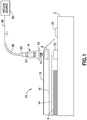
- FIG. 1 is a diagram representing an exploded side view of a typical vacuum bag assembly 10 for evacuating a sealed space underneath a vacuum bag 18 and surrounding a composite part 4 laid on a tool 2.
- a release film 14 overlies the composite part 4.
- a breather cloth 16 overlies the release film.
- a vacuum bag 18 (made, e.g., of a sheet of nylon film) covers the breather cloth 16.
- the vacuum bag 18 is typically sealed to the surface of tool 2 by sealing tape 20 which surrounds the breather cloth 16 and the composite part 4. In an unevacuated state, the vacuum bag 18 fits loosely over the breather cloth 16, leaving open space therebetween.
- the outer peripheries of the release film 14 and breather cloth 16 are sandwiched between an edge breather 22 (placed on the tool 2) and a vacuum probe base 6 having an internal threads for threadably engaging an externally threaded portion 12 of a vacuum probe 8.
- the release film 14 does not end at the same place as the breather 16 and the edge breather 22. It will usually end halfway over the edge breather 22 or prior to it. This is because the breather 16 should make contact with the edge breather 22 to facilitate air flow. If the release film 14 is non-porous, the release film 14 can cut off flow.
- the coupling of the vacuum probe 8 to the vacuum probe base 6 is accomplished by forming an opening (not shown) in the vacuum bag 18, through which the externally threaded portion 12 of vacuum probe 8 is passed and then screwed into an internally threaded hole in the vacuum probe base 6.
- a sealant gasket 52 which is made of a compressible material that is squeezed between opposing surfaces of vacuum probe 8 and vacuum probe base 6 to seal around the opening in the vacuum bag 18.
- the vacuum probe 8 is connected to a vacuum source 30 by means of a vacuum hose 28.
- a common type of coupling used to connect a vacuum hose 28 to a vacuum probe 8 is a valved quick connect/disconnect coupling.
- the structure and operation of various types of valved quick connect/disconnect couplings are well known, including many such couplings which are commercially available from Swagelok Company, Solon, Ohio. More specifically, detailed descriptions of various valved quick connect/disconnect couplings can be found in U.S. Patents Nos. 4,378,028 , 4,982,761 and 6,669,168 , which patents are assigned to Swagelok Company. In the example, depicted in FIG.
- the vacuum hose 28 is coupled to the vacuum probe 8 by inserting a male quick connect/disconnect coupling element 24 disposed at one end of the vacuum probe 8 into a female quick connect/disconnect coupling element 26 disposed at one end of the vacuum hose 28.
- the female quick connect/disconnect coupling element 26 in turn incorporates a valve core (not shown in the drawings) that comes into contact with and then pushes inward a valve element (not shown in FIG. 1 , but see valve element 38 in FIG. 2 ) that is incorporated in the vacuum probe 8.
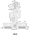
- FIG. 2 is a diagram representing a partially sectional view of a vacuum probe 32a comprising a male quick connect/disconnect coupling element 24 and a flat probe bottom part 36 in accordance with one embodiment.
- This vacuum probe 32a has a valve seat 50 that surrounds an opening 58 and a valve element 38 that bears against the valve seat 50 in the absence of a downward force sufficient to overcome the resistance of a spring 60 that urges the valve element 38 toward the valve seat 50.
- the spring 60 is seated on a spring seat 62, which may take the form of an inwardly directed annular flange inside the vacuum channel 34 of the vacuum probe 32a.
- the valve element 38 bears against a valve seat 50 inside the vacuum probe 32a.
- FIG. 2 depicts a situation in which the valve element 38 is separated from the valve seat 50, which separation allows air to flow from the vacuum channel 34 out through opening 58 when vacuum pressure is applied at opening 58.
- the valve element 38 comprises a forward portion 40 which protrudes through opening 58.
- the end face of the forward portion 40 of the valve element 38 is acted upon by the valve core of the female quick connect/disconnect coupling element 26 of the vacuum hose 28. More specifically, the valve core (not shown in the drawings) forces the valve element 38 to displace downward and away from the valve seat 50.
- the valve element 38 is displaceable along an axis of the vacuum channel 34. This inward displacement causes the valve element 38 to move away from the valve seat 50, thereby opening the vacuum channel 34 inside the vacuum probe 32a.
- the sealed space underneath the vacuum bag 18 can be evacuated by applying vacuum pressure from the vacuum source 30 via the vacuum hose 28 and the vacuum probe 32a.
- the vacuum probe 32a comprises a vacuum channel 34 having an axis and openings 58 and 59 at opposite ends thereof.
- the vacuum probe 32a further comprises a sharpened body 46 that points away from opening 58 of the vacuum channel 34 and projects outside of the vacuum channel 34 in a vicinity of opening 59.
- the vacuum probe 32a comprises: a valve seat 50 surrounding the opening 58 of the vacuum channel 34; a valve element 38 that is axially displaceable in the vacuum channel 34 between first and second axial positions, the valve element 38 being in contact with the valve seat while in the first axial (i.e., closed) position and being separated from the valve seat 50 while in the second axial (i.e., open) position; and a rod 42 disposed in the vacuum channel 34.
- the rod 42 has a first end to which the sharpened body 46 is fixedly coupled by means of an air-permeable sharpened body support element 44 and a second end that is connected to the valve element 38.
- the sharpened body 46 is axially displaceable in tandem with the valve element 38 as the valve element 38 moves toward the second axial position.
- the sharpened body 46 projects outside the vacuum channel 34 when the valve element 38 is in the second axial position.
- the vacuum probe 32a when the vacuum probe 32a is added and sealed to the exterior surface of a vacuum bag 18 using donut-shaped sealing material 48a that is tacky on both sides, the vacuum probe 32a itself becomes a sealed-off environment.
- sealing material can be utilized, such as sealing tape or a sealing gasket, provided that the sealing element has sufficient height to create a volume of space under the bottom of the vacuum probe 32a that allows the sharpened body 46 to project downward for puncturing the uplifted vacuum bag.
- the donut-shaped sealing material 48a may comprise a conformable, tacky, putty-like material for removably adhering the vacuum probe 32a to the exterior surface of the vacuum bag 18.
- the donut-shaped sealing material 48a may comprise a partially cured rubber compound that is inherently tacky and that may be used to form an airtight seal between the vacuum probe 32a and the exterior surface of the vacuum bag 18.
- the donut-shaped sealing material 48a may be provided in a composition that is generally soft and pliable during room-temperature installation of the vacuum bag assembly 10, and at elevated temperatures associated with processing (e.g., curing or solidifying) the composite part 4.
- the sharpened body 46 Prior to quick connection of the vacuum probe 32a and the vacuum hose 28, the sharpened body 46 is recessed slightly (not shown in the drawings) inside the vacuum channel 34 for safety reasons, but is displaced downward and toward the vacuum bag 18 during vacuum hose quick connection. During quick connection, the sharpened body 46 and the valve element 38 move in tandem in the vacuum channel 34 until the sharpened body 46 projects through opening 59 and outside the vacuum channel 34, as depicted in FIG. 2 . A vacuum pressure applied via the vacuum hose 28 pulls the vacuum bag 18 upwards and towards the sharpened body 46, which punctures the vacuum bag 18, thereby enabling air under the vacuum bag 18 to be evacuated via the vacuum probe 32a as vacuum pressure continues to be applied.
- FIG. 3 is a diagram representing an orthographic view of a portion of a device which is incorporated in the vacuum probe 32a depicted in FIG. 2 and which is designed to puncture a vacuum bag 18 in response to a quick connection of vacuum probe 32a and vacuum hose 28.
- This device is an air-permeable sharpened body support element 44 in the form of a disk having six through-holes 54 which allow air to flow upward in the vacuum channel 34 during evacuation.
- the first end of rod 42 and the sharpened body 46 are affixed to the air-permeable sharpened body support element 44 to form a rigid assembly that displaces (e.g., slides) inside the vacuum channel 34 in tandem with the valve element 38 (not shown in FIG. 3 ).
- the air-permeable sharpened body support element 44 may be in the form of a plug of porous material configured to slide up and down inside the vacuum channel 34.
- FIG. 4 is a diagram representing a partially sectional view of a vacuum probe 32b in accordance with another embodiment. As seen in FIG. 4 , when the vacuum probe 32b is added and sealed to the exterior surface of a vacuum bag 18 using a stack of two layers of donut-shaped sealing material 48a and 48b having adhesive on both sides, the vacuum probe 32b itself becomes a sealed-off environment. More than two layers of donut-shaped sealing material can be stacked.
- vacuum probe 32b has a valve seat 50 that surrounds an opening 58 and a valve element 38 that bears against the valve seat 50, which elements interact in the manner previously described.
- FIG. 4 depicts a situation in which the valve element 38 is separated from the valve seat 50, which separation allows air to flow from the vacuum channel 34 out through opening 58 when vacuum pressure is applied at opening 58.
- the valve element 38 comprises a forward portion 40 which protrudes through opening 58.
- the end face of the forward portion 40 of the valve element 38 is acted upon by the valve core of the female quick connect/disconnect coupling element 26 of the vacuum hose 28 in the manner previously described with reference to FIG. 2 to cause the valve element 38 to move away from the valve seat 50, thereby opening the vacuum channel 34.
- the vacuum probe 32b comprises an externally threaded portion 12 projecting downward from a bottom of the vacuum probe 32b.
- the vacuum channel 34 extends from opening 58 at the top of vacuum probe 32b to opening 59 at the bottom of the externally threaded portion 12.
- the externally threaded portion 12 projects into the space that is surrounded by the layers of donut-shaped sealing material 48a and 48b.
- a sharpened body 46 projects out of the vacuum channel 34 and beyond opening 59 formed in the bottom of the externally threaded portion 12. It should be appreciated that although vacuum probe 32b includes an externally threaded portion 12, the external threads are not used.
- This capability enables some existing vacuum probes having an externally threaded portion for threaded coupling with a base to be modified or supplemented to provide the vacuum bag puncturing capability disclosed herein without using a base (see, e.g., base 6 in FIG. 1 ).
- the vacuum probe 32b depicted in FIG. 4 does not have a rod 42. Instead the vacuum probe 32b comprises an air-permeable sharpened body support element 56 in the form of a plug of porous material, which porous plug is inserted into the bottommost portion of the vacuum channel 34.
- the air-permeable sharpened body support element 56 which supports the sharpened body 46 may comprise a disk having a plurality of through-holes. Whether in the form of a plug or a disk, the material of the air-permeable sharpened body support element 56 should be sufficiently malleable to allow the plug or disk to be easily but securely press fit or wedged into the vacuum channel and easily removed.
- the air-permeable sharpened body support element 56 comprises an annular flange 58 that bears against a bottom surface of the externally threaded portion 12, serving to block further insertion of the plug or disk into the vacuum channel 34.
- the sharpened body 46 is not recessed into the vacuum channel and instead projects downward toward the vacuum bag 18.
- a vacuum pressure is applied via the vacuum hose 28 and vacuum probe 32b pulls the vacuum bag 18 upwards and towards the sharpened body 46, which punctures the vacuum bag 18. This puncture enables air underneath the vacuum bag 18 to be evacuated via the vacuum probe 32b as vacuum pressure continues to be applied.
- FIG. 5 is a diagram representing a partially sectional view of a vacuum probe 32c in accordance with a further embodiment.
- FIG. 5A is a diagram representing a magnified view of a portion of the vacuum probe 32c depicted in FIG. 5 . Except for the components depicted in FIG. 5A , the only other structural difference between vacuum probe 32b depicted in FIG. 4 and vacuum probe 32c depicted in FIG. 5 is that the upper end of the rod 42 seen in FIG. 5 is in abutment with, not connected to the valve element 38. This is a consequence of the fact that the rod 42 is inserted into the vacuum channel 34 from the bottom of a vacuum probe having an externally threaded portion 12 (e.g., of the type depicted in FIG. 1 ).
- an externally threaded portion 12 e.g., of the type depicted in FIG. 1 .
- a spring 74 urges the sharpened body 46 upward toward a recessed position (not shown in the drawings).
- the sharpened body 46 will reach a position in which its tip projects outside of the vacuum probe and is exposed to the uplifting outer vacuum bag 18.
- FIG. 5A is a diagram representing a magnified view of a portion of the vacuum probe 32c depicted in FIG. 5 .
- the vacuum probe 32c comprises an externally threaded portion 12 projecting downward from a bottom of the vacuum probe.
- the vacuum probe 32c further comprises an internally threaded end cap 64 that is threadably coupled to the externally threaded portion 12 and a chamber 68 which is affixed to the internally threaded end cap 64.
- the internally threaded end cap 64 comprises an opening 66 through which the sharpened body 46 passes when deployed, while the chamber 68 comprises an opening 72 through which the rod 42 passes.
- the rod 42 has a bottom end affixed to an air-permeable sharpened body support element 70 and a top end (not shown in FIG. 5A , but see FIG. 5 ) that abuts the valve element 38.
- the air-permeable sharpened body support element 70 (which may, for example, be similar to the air-permeable sharpened body support element 44 depicted in FIG. 3 ) supports the sharpened body 46.
- the sharpened body 46 is axially displaceable in tandem with the valve element 38 as the valve element 38 moves toward its second axial position.
- the air-permeable sharpened body support element 70 is configured to slide up and down inside the chamber 68.
- a spring 74 is disposed between the air-permeable sharpened body support element 70 and the internally threaded end cap 64 for urging the air-permeable sharpened body support element 70 upward.
- the tip of the sharpened body 46 will be recessed (i.e., will not project below the bottom surface of the internally threaded end cap 64.
- the valve element 38 is displaced downward and reaches its second axial position, the tip of the sharpened body 46 will project below the bottom surface of the internally threaded end cap 64.
- the internally threaded end cap 64 may comprise through-holes 76 which allow air to flow into the chamber 68, while the chamber 68 may comprise through-holes 78 which allow air to flow out of the chamber 68 and into the vacuum channel 34.
- the sharpened body support element is not air-permeable, in which case the through-holes 78 in the chamber 68 may be placed at a lower elevation, i.e., below the elevation of the bottom surface of the sharpened body support element when the latter is in its lowermost position.
Landscapes
- Engineering & Computer Science (AREA)
- Mechanical Engineering (AREA)
- General Engineering & Computer Science (AREA)
- Chemical & Material Sciences (AREA)
- Composite Materials (AREA)
- Physics & Mathematics (AREA)
- Fluid Mechanics (AREA)
- Casting Or Compression Moulding Of Plastics Or The Like (AREA)
- Check Valves (AREA)
Abstract
Description
- This disclosure relates to manufacturing of parts made of composite material. In particular, this disclosure relates to applying vacuum pressure to composite parts made of fiber-reinforced plastic material.
- The use of fiber reinforced/resin matrix composite materials in the manufacture of articles and components is becoming increasingly widespread in a number of industries, including the aircraft industry. Such composite materials include, for example, carbon fiber-reinforced/epoxy resin matrix materials and glass fiber-reinforced/polyimide resin matrix materials. In a common manufacturing procedure for producing articles and components from composite materials, a plurality of layers of the material, typically called a "lay-up", are held on a tool, and the tool with the lay-up thereon is placed in an autoclave, which applies heat and pressure, to cure the resin matrix. During the curing process, the lay-up is covered by an impermeable, flexible film, often referred to as the "vacuum bag" and sealed to the tool with a vacuum bag sealant. In this way, the autoclave pressure is transmitted uniformly over the surface of the lay-up. The uniform pressure produces a high-quality finished article or component and is particularly important in the manufacture of aircraft parts which must meet stringent tolerance limitations and/or structural strength requirements. In preparation for the curing procedure, a vacuum probe (also known as a vacuum port) is placed in fluid communication with a sealed space underneath the vacuum bag and connected to a vacuum line. A vacuum is drawn through the line and the probe to evacuate air between the vacuum bag and the lay-up. This presses the vacuum bag against the lay-up so that the desired uniform pressure will be achieved.
- When vacuum is used to extract air from between the tool and vacuum bag using a matrix of breather material, a pressure differential is created. This differential creates a pressure from the outside the vacuum bag pressing on the lay-up. When placed in an autoclave with higher pressure and heat, these higher pressures are transferred to the lay-up. Currently, in a typical composite part/vacuum bag setup, air and volatiles are removed from the lay-up side of the vacuum bag through one or more vacuum probes. These probes require bases to be installed inside the composite vacuum bag. The vacuum probes and vacuum line system are used to maintain the pressure differential.
- Heated volatiles and moisture can overload the vacuum system. Also leaks in the system can affect the lay-up quality. The use of additional vacuum probes ensures sufficient vacuum is applied to composite parts and helps to minimize these effects. Frequently, if a technician wants to apply additional vacuum, the technician pulls up a portion of the vacuum bag sealant to insert an additional vacuum probe base. This process disturbs the existing vacuum condition in the bag. For complex parts, adding probes may not be possible or may require the technician to rework the vacuum bag in many areas due to the loss of vacuum. Adding new probes may also deform the bag, remove existing bag pleats, or introduce bag wrinkles. There is a need for improved systems and methods for applying sufficient vacuum to composite parts, for example, through the addition of vacuum probes in a vacuum bagged part.
- The subject matter disclosed in detail below is directed to systems and methods for applying vacuum pressure to composite parts. In accordance with some embodiments, a vacuum probe can be produced specifically for adding on the exterior surface of a vacuum bag. The vacuum probe incorporates a device that punctures the vacuum bag during the process of connecting the vacuum probe to a vacuum source by means of a vacuum hose, e.g., during a quick connect/disconnect coupling of the male end of the vacuum probe and the female end of the vacuum hose by inserting the former into the latter. In accordance with other embodiments, some existing vacuum probes having an externally threaded portion for threaded coupling with a base that can be modified or supplemented to produce a similar effect without using the base.
- In accordance with the aforementioned embodiments, when a vacuum probe is added and sealed to the exterior surface of the vacuum bag using vacuum bag sealant tape in the shape of a donut, the vacuum probe itself becomes a sealed-off environment. [As used herein, the term "donut-shaped" means having a shape of a continuous mass of material that surrounds and bounds an open volume.] The vacuum probe comprises a sharpened body that is recessed slightly for safety reasons, but is displaced downward and toward the vacuum bag during vacuum hose quick connection. When connected, the sharpened body and a valve element move in tandem in the vacuum channel until the sharpened body projects outside the vacuum probe. A vacuum pressure applied via the vacuum hose pulls the vacuum bag upwards and towards the sharpened body, which punctures the vacuum bag, thereby enabling air under the vacuum bag to be evacuated via the added vacuum probe as vacuum pressure continues to be applied.
- Although various embodiments of systems and methods for applying vacuum pressure to composite parts are described in some detail later herein, one or more of those embodiments may be characterized by one or more of the following aspects.
- One aspect of the subject matter disclosed in detail hereinafter is a method for applying vacuum pressure to a composite part, comprising: (a) placing a composite part on a tool; (b) placing a flexible sealant tape on the tool along a perimeter that surrounds the composite part; (c) laying a vacuum bag over the composite part and in contact with the sealant tape; (d) placing a vacuum probe overlying a portion of the vacuum bag with sealing material disposed between the vacuum probe and the vacuum bag, the vacuum probe comprising a sharpened body; (e) coupling a vacuum hose to an end of the vacuum probe in a manner that causes a valve element to separate from a valve seat inside a vacuum channel of the vacuum probe; and (f) applying a vacuum pressure inside the vacuum channel by way of the vacuum hose, as a result of which a portion of the vacuum bag surrounded by the sealing material is pulled toward and punctured by the sharpened body. In accordance with some embodiments, coupling the vacuum hose to the end of the vacuum probe also causes the sharpened body to move in tandem with the valve element in a direction away from the valve seat until the sharpened body protrudes outside the vacuum channel and into a space overlying the vacuum bag. In one proposed implementation, step (e) comprises inserting a male quick connect/disconnect coupling element of the vacuum probe into a female quick connect/disconnect coupling element of the vacuum hose.
- In accordance with some embodiments of the method described in the preceding paragraph, the vacuum probe comprises an externally threaded portion that projects into a space bounded by the sealing material. In accordance with one embodiment, the method further comprises threadably coupling an internally threaded end cap to the externally threaded portion of the vacuum probe, wherein the sharpened body projects through an opening in and is axially displaceable relative to the internally threaded end cap. In accordance with another embodiment, the method further comprises inserting a portion of a plug made of porous material in a portion of the vacuum channel disposed in the externally threaded portion of the vacuum probe, wherein the sharpened body projects from the plug.
- Another aspect of the subject matter disclosed in detail hereinafter is a vacuum probe comprising: a vacuum channel having an axis and first and second openings at opposite ends thereof; and a sharpened body that points away from the first opening of the vacuum channel and projects outside of the vacuum channel in a vicinity of the second opening of the vacuum channel.
- In accordance with some embodiments, the vacuum probe further comprises: a valve seat surrounding the first opening of the vacuum channel; a valve element that is axially displaceable in the vacuum channel between first and second axial positions, the valve element being in contact with the valve seat while in the first axial position and being separated from the valve seat while in the second axial position; and a rod disposed in the vacuum channel, the rod having a first end to which the sharpened body is fixedly coupled and a second end that is either connected to or in abutment with the valve element. In these embodiments, the sharpened body is axially displaceable in tandem with the valve element as the valve element moves toward the second axial position and projects outside the vacuum channel when the valve element is in the second axial position.
- In cases where the second end of the rod is connected to the valve element, the vacuum probe further comprises an air-permeable sharpened body support element to which the first end of the rod and the sharpened body are affixed. In one proposed implementation, the air-permeable sharpened body support element is a disk having at least one through-hole. In cases where the second end of the rod is in abutment with the valve element, the vacuum probe further comprises a spring that urges the rod toward the valve element.
- In accordance with some embodiments, the vacuum probe further comprises an externally threaded portion projecting downward from a bottom of the vacuum probe. In one proposed implementation, the vacuum probe further comprises an internally threaded end cap threadably coupled to the externally threaded portion and a chamber affixed to the internally threaded end cap, wherein the internally threaded end cap comprises an opening through which the sharpened body passes, while the chamber comprises an opening through which the rod passes. To facilitate the flow of air through the vacuum probe during evacuation, the internally threaded end cap may comprise through-holes which allow air to flow into the chamber, while the chamber may comprise through-holes which allow air to flow out of the chamber and into the vacuum channel. In another proposed implementation, the vacuum probe further comprises an air-permeable sharpened body support element in the form of a porous plug seated inside the portion of the vacuum channel that is disposed in the externally threaded portion and to which the sharpened body is affixed.
- A further aspect of the subject matter disclosed in detail hereinafter is a system for applying vacuum pressure to a composite part, comprising: a tool that supports a composite part; a vacuum bag overlying the composite part; a flexible sealant tape that seals the vacuum bag to the tool along a perimeter that surrounds the composite part; sealing material on an exterior surface of the vacuum bag within the perimeter and separated from the composite part; a vacuum probe on top of the sealing material; and a vacuum hose coupled to an end of the vacuum probe in a manner that causes a valve element of the vacuum probe to axially displace from the first axial position to the second axial position during coupling. The vacuum probe comprises a vacuum channel having an axis and first and second openings at opposite ends thereof, a valve seat surrounding the first opening, a valve element that is axially displaceable in the vacuum channel between a first axial position in contact with the valve seat and a second axial position separated from the valve seat, and a sharpened body that points away from the first opening of the vacuum channel and projects outside of the vacuum channel in a vicinity of the second opening of the vacuum channel.
- In accordance with some embodiments, the system further comprises a rod having a first end to which the sharpened body is fixedly coupled and a second end that is either connected to or in abutment with the valve element, wherein the sharpened body is axially displaceable in tandem with the valve element as the valve element moves toward the second axial position and projects into a space surrounded by the sealing material when the valve element is in the second axial position. In cases where the second end of the rod is connected to the valve element, the vacuum probe further comprises an air-permeable sharpened body support element to which the first end of the rod and the sharpened body are affixed. In cases where the second end of the rod abuts the valve element, the vacuum probe further comprises: an externally threaded portion projecting into the space surrounded by the sealing material; an internally threaded end cap threadably coupled to the externally threaded portion of the vacuum probe; and a chamber affixed to the internally threaded end cap, wherein the internally threaded end cap comprises an opening through which the sharpened body passes, while the chamber comprises an opening through which the rod passes.
- Other aspects of systems and methods for applying vacuum pressure to composite parts are disclosed below.
- The features, functions and advantages discussed in the preceding section can be achieved independently in various embodiments or may be combined in yet other embodiments. Various embodiments will be hereinafter described with reference to drawings for the purpose of illustrating the above-described and other aspects. None of the diagrams briefly described in this section are drawn to scale.
-
FIG. 1 is a diagram representing an exploded side view of a vacuum bag assembly for evacuating a sealed space underneath a vacuum bag and surrounding a composite part laid on a tool. -
FIG. 2 is a diagram representing a partially sectional view of a vacuum probe in accordance with one embodiment. -
FIG. 3 is a diagram representing an orthographic view of a portion of a device which is incorporated in the vacuum probe depicted inFIG. 2 and which is designed to puncture a vacuum bag in response to vacuum hose hookup. -
FIG. 4 is a diagram representing a partially sectional view of a vacuum probe in accordance with another embodiment. -
FIG. 5 is a diagram representing a partially sectional view of a vacuum probe in accordance with a further embodiment. -
FIG. 5A is a diagram representing a magnified view of a portion of the vacuum probe depicted inFIG. 5 . - Reference will hereinafter be made to the drawings in which similar elements in different drawings bear the same reference numerals.
- For the purpose of illustration, systems and methods for applying vacuum pressure to composite parts will now be described in some detail. However, not all features of an actual implementation are described in this specification. A person skilled in the art will appreciate that in the development of any such embodiment, numerous implementation-specific decisions must be made to achieve the developer's specific goals, such as compliance with system-related and business-related constraints, which will vary from one implementation to another. Moreover, it will be appreciated that such a development effort might be complex and time-consuming, but would nevertheless be a routine undertaking for those of ordinary skill in the art having the benefit of this disclosure.
-
FIG. 1 is a diagram representing an exploded side view of a typicalvacuum bag assembly 10 for evacuating a sealed space underneath avacuum bag 18 and surrounding acomposite part 4 laid on atool 2. Arelease film 14 overlies thecomposite part 4. Abreather cloth 16 overlies the release film. (As used herein, the term "breather" means a porous material.) In turn, a vacuum bag 18 (made, e.g., of a sheet of nylon film) covers thebreather cloth 16. Thevacuum bag 18 is typically sealed to the surface oftool 2 by sealingtape 20 which surrounds thebreather cloth 16 and thecomposite part 4. In an unevacuated state, thevacuum bag 18 fits loosely over thebreather cloth 16, leaving open space therebetween. - Still referring to
FIG. 1 , the outer peripheries of therelease film 14 andbreather cloth 16 are sandwiched between an edge breather 22 (placed on the tool 2) and avacuum probe base 6 having an internal threads for threadably engaging an externally threadedportion 12 of avacuum probe 8. Typically therelease film 14 does not end at the same place as thebreather 16 and theedge breather 22. It will usually end halfway over theedge breather 22 or prior to it. This is because thebreather 16 should make contact with theedge breather 22 to facilitate air flow. If therelease film 14 is non-porous, therelease film 14 can cut off flow. - The coupling of the
vacuum probe 8 to thevacuum probe base 6 is accomplished by forming an opening (not shown) in thevacuum bag 18, through which the externally threadedportion 12 ofvacuum probe 8 is passed and then screwed into an internally threaded hole in thevacuum probe base 6. Whenvacuum probe 8 andvacuum probe base 6 are assembled (not shown inFIG. 1 ), the opening in thevacuum bag 18 is sealed by asealant gasket 52, which is made of a compressible material that is squeezed between opposing surfaces ofvacuum probe 8 andvacuum probe base 6 to seal around the opening in thevacuum bag 18. - The
vacuum probe 8 is connected to avacuum source 30 by means of avacuum hose 28. A common type of coupling used to connect avacuum hose 28 to avacuum probe 8 is a valved quick connect/disconnect coupling. The structure and operation of various types of valved quick connect/disconnect couplings are well known, including many such couplings which are commercially available from Swagelok Company, Solon, Ohio. More specifically, detailed descriptions of various valved quick connect/disconnect couplings can be found inU.S. Patents Nos. 4,378,028 ,4,982,761 and6,669,168 , which patents are assigned to Swagelok Company. In the example, depicted inFIG. 1 , thevacuum hose 28 is coupled to thevacuum probe 8 by inserting a male quick connect/disconnect coupling element 24 disposed at one end of thevacuum probe 8 into a female quick connect/disconnect coupling element 26 disposed at one end of thevacuum hose 28. The female quick connect/disconnect coupling element 26 in turn incorporates a valve core (not shown in the drawings) that comes into contact with and then pushes inward a valve element (not shown inFIG. 1 , but seevalve element 38 inFIG. 2 ) that is incorporated in thevacuum probe 8. -
FIG. 2 is a diagram representing a partially sectional view of avacuum probe 32a comprising a male quick connect/disconnect coupling element 24 and a flat probebottom part 36 in accordance with one embodiment. Thisvacuum probe 32a has avalve seat 50 that surrounds anopening 58 and avalve element 38 that bears against thevalve seat 50 in the absence of a downward force sufficient to overcome the resistance of aspring 60 that urges thevalve element 38 toward thevalve seat 50. Thespring 60 is seated on aspring seat 62, which may take the form of an inwardly directed annular flange inside thevacuum channel 34 of thevacuum probe 32a. In a closed state of thevacuum probe 32a, thevalve element 38 bears against avalve seat 50 inside thevacuum probe 32a.FIG. 2 depicts a situation in which thevalve element 38 is separated from thevalve seat 50, which separation allows air to flow from thevacuum channel 34 out throughopening 58 when vacuum pressure is applied atopening 58. - As seen in
FIG. 2 , thevalve element 38 comprises aforward portion 40 which protrudes throughopening 58. During quick connection, the end face of theforward portion 40 of thevalve element 38 is acted upon by the valve core of the female quick connect/disconnect coupling element 26 of thevacuum hose 28. More specifically, the valve core (not shown in the drawings) forces thevalve element 38 to displace downward and away from thevalve seat 50. Thevalve element 38 is displaceable along an axis of thevacuum channel 34. This inward displacement causes thevalve element 38 to move away from thevalve seat 50, thereby opening thevacuum channel 34 inside thevacuum probe 32a. When thevacuum probe 32a is open, the sealed space underneath thevacuum bag 18 can be evacuated by applying vacuum pressure from thevacuum source 30 via thevacuum hose 28 and thevacuum probe 32a. - Still referring to
FIG. 2 , thevacuum probe 32a comprises avacuum channel 34 having an axis andopenings vacuum probe 32a further comprises a sharpenedbody 46 that points away from opening 58 of thevacuum channel 34 and projects outside of thevacuum channel 34 in a vicinity ofopening 59. As previously mentioned, thevacuum probe 32a comprises: avalve seat 50 surrounding theopening 58 of thevacuum channel 34; avalve element 38 that is axially displaceable in thevacuum channel 34 between first and second axial positions, thevalve element 38 being in contact with the valve seat while in the first axial (i.e., closed) position and being separated from thevalve seat 50 while in the second axial (i.e., open) position; and arod 42 disposed in thevacuum channel 34. Therod 42 has a first end to which the sharpenedbody 46 is fixedly coupled by means of an air-permeable sharpenedbody support element 44 and a second end that is connected to thevalve element 38. In this embodiment, the sharpenedbody 46 is axially displaceable in tandem with thevalve element 38 as thevalve element 38 moves toward the second axial position. In addition, the sharpenedbody 46 projects outside thevacuum channel 34 when thevalve element 38 is in the second axial position. - As seen in
FIG. 2 , when thevacuum probe 32a is added and sealed to the exterior surface of avacuum bag 18 using donut-shapedsealing material 48a that is tacky on both sides, thevacuum probe 32a itself becomes a sealed-off environment. Different forms of sealing material can be utilized, such as sealing tape or a sealing gasket, provided that the sealing element has sufficient height to create a volume of space under the bottom of thevacuum probe 32a that allows the sharpenedbody 46 to project downward for puncturing the uplifted vacuum bag. The donut-shapedsealing material 48a may comprise a conformable, tacky, putty-like material for removably adhering thevacuum probe 32a to the exterior surface of thevacuum bag 18. In this regard, the donut-shapedsealing material 48a may comprise a partially cured rubber compound that is inherently tacky and that may be used to form an airtight seal between thevacuum probe 32a and the exterior surface of thevacuum bag 18. The donut-shapedsealing material 48a may be provided in a composition that is generally soft and pliable during room-temperature installation of thevacuum bag assembly 10, and at elevated temperatures associated with processing (e.g., curing or solidifying) thecomposite part 4. - Prior to quick connection of the
vacuum probe 32a and thevacuum hose 28, the sharpenedbody 46 is recessed slightly (not shown in the drawings) inside thevacuum channel 34 for safety reasons, but is displaced downward and toward thevacuum bag 18 during vacuum hose quick connection. During quick connection, the sharpenedbody 46 and thevalve element 38 move in tandem in thevacuum channel 34 until the sharpenedbody 46 projects throughopening 59 and outside thevacuum channel 34, as depicted inFIG. 2 . A vacuum pressure applied via thevacuum hose 28 pulls thevacuum bag 18 upwards and towards the sharpenedbody 46, which punctures thevacuum bag 18, thereby enabling air under thevacuum bag 18 to be evacuated via thevacuum probe 32a as vacuum pressure continues to be applied. -
FIG. 3 is a diagram representing an orthographic view of a portion of a device which is incorporated in thevacuum probe 32a depicted inFIG. 2 and which is designed to puncture avacuum bag 18 in response to a quick connection ofvacuum probe 32a andvacuum hose 28. This device is an air-permeable sharpenedbody support element 44 in the form of a disk having six through-holes 54 which allow air to flow upward in thevacuum channel 34 during evacuation. The first end ofrod 42 and the sharpenedbody 46 are affixed to the air-permeable sharpenedbody support element 44 to form a rigid assembly that displaces (e.g., slides) inside thevacuum channel 34 in tandem with the valve element 38 (not shown inFIG. 3 ). In accordance with alternative embodiments, the air-permeable sharpenedbody support element 44 may be in the form of a plug of porous material configured to slide up and down inside thevacuum channel 34. -
FIG. 4 is a diagram representing a partially sectional view of avacuum probe 32b in accordance with another embodiment. As seen inFIG. 4 , when thevacuum probe 32b is added and sealed to the exterior surface of avacuum bag 18 using a stack of two layers of donut-shapedsealing material vacuum probe 32b itself becomes a sealed-off environment. More than two layers of donut-shaped sealing material can be stacked. - As was the case in
vacuum probe 32a depicted inFIG. 2 ,vacuum probe 32b has avalve seat 50 that surrounds anopening 58 and avalve element 38 that bears against thevalve seat 50, which elements interact in the manner previously described.FIG. 4 depicts a situation in which thevalve element 38 is separated from thevalve seat 50, which separation allows air to flow from thevacuum channel 34 out throughopening 58 when vacuum pressure is applied atopening 58. As seen inFIG. 4 , thevalve element 38 comprises aforward portion 40 which protrudes throughopening 58. During quick connection, the end face of theforward portion 40 of thevalve element 38 is acted upon by the valve core of the female quick connect/disconnect coupling element 26 of thevacuum hose 28 in the manner previously described with reference toFIG. 2 to cause thevalve element 38 to move away from thevalve seat 50, thereby opening thevacuum channel 34. - Still referring to
FIG. 4 , thevacuum probe 32b comprises an externally threadedportion 12 projecting downward from a bottom of thevacuum probe 32b. Thevacuum channel 34 extends from opening 58 at the top ofvacuum probe 32b to opening 59 at the bottom of the externally threadedportion 12. The externally threadedportion 12 projects into the space that is surrounded by the layers of donut-shapedsealing material body 46 projects out of thevacuum channel 34 and beyond opening 59 formed in the bottom of the externally threadedportion 12. It should be appreciated that althoughvacuum probe 32b includes an externally threadedportion 12, the external threads are not used. This capability enables some existing vacuum probes having an externally threaded portion for threaded coupling with a base to be modified or supplemented to provide the vacuum bag puncturing capability disclosed herein without using a base (see, e.g.,base 6 inFIG. 1 ). - In contrast to the
vacuum probe 32a depicted inFIG. 2 , thevacuum probe 32b depicted inFIG. 4 does not have arod 42. Instead thevacuum probe 32b comprises an air-permeable sharpenedbody support element 56 in the form of a plug of porous material, which porous plug is inserted into the bottommost portion of thevacuum channel 34. In an alternative embodiment, the air-permeable sharpenedbody support element 56 which supports the sharpenedbody 46 may comprise a disk having a plurality of through-holes. Whether in the form of a plug or a disk, the material of the air-permeable sharpenedbody support element 56 should be sufficiently malleable to allow the plug or disk to be easily but securely press fit or wedged into the vacuum channel and easily removed. Preferably the air-permeable sharpenedbody support element 56 comprises anannular flange 58 that bears against a bottom surface of the externally threadedportion 12, serving to block further insertion of the plug or disk into thevacuum channel 34. In this embodiment, the sharpenedbody 46 is not recessed into the vacuum channel and instead projects downward toward thevacuum bag 18. When a vacuum pressure is applied via thevacuum hose 28 andvacuum probe 32b pulls thevacuum bag 18 upwards and towards the sharpenedbody 46, which punctures thevacuum bag 18. This puncture enables air underneath thevacuum bag 18 to be evacuated via thevacuum probe 32b as vacuum pressure continues to be applied. -
FIG. 5 is a diagram representing a partially sectional view of avacuum probe 32c in accordance with a further embodiment.FIG. 5A is a diagram representing a magnified view of a portion of thevacuum probe 32c depicted inFIG. 5 . Except for the components depicted inFIG. 5A , the only other structural difference betweenvacuum probe 32b depicted inFIG. 4 andvacuum probe 32c depicted inFIG. 5 is that the upper end of therod 42 seen inFIG. 5 is in abutment with, not connected to thevalve element 38. This is a consequence of the fact that therod 42 is inserted into thevacuum channel 34 from the bottom of a vacuum probe having an externally threaded portion 12 (e.g., of the type depicted inFIG. 1 ). However, as long as the end of therod 42 is in contact with thevalve element 38, then the sharpenedbody 46 will move downward in tandem with thevalve element 38 during quick connection in the manner previously described. As will be explained in more detail with reference toFIG. 5A , aspring 74 urges the sharpenedbody 46 upward toward a recessed position (not shown in the drawings). When the sharpenedbody 46 moves downward in tandem with thevalve element 38 during quick connection, the sharpenedbody 46 will reach a position in which its tip projects outside of the vacuum probe and is exposed to the upliftingouter vacuum bag 18. -
FIG. 5A is a diagram representing a magnified view of a portion of thevacuum probe 32c depicted inFIG. 5 . Thevacuum probe 32c comprises an externally threadedportion 12 projecting downward from a bottom of the vacuum probe. Thevacuum probe 32c further comprises an internally threadedend cap 64 that is threadably coupled to the externally threadedportion 12 and achamber 68 which is affixed to the internally threadedend cap 64. The internally threadedend cap 64 comprises anopening 66 through which the sharpenedbody 46 passes when deployed, while thechamber 68 comprises anopening 72 through which therod 42 passes. - The
rod 42 has a bottom end affixed to an air-permeable sharpenedbody support element 70 and a top end (not shown inFIG. 5A , but seeFIG. 5 ) that abuts thevalve element 38. The air-permeable sharpened body support element 70 (which may, for example, be similar to the air-permeable sharpenedbody support element 44 depicted inFIG. 3 ) supports the sharpenedbody 46. In this embodiment, the sharpenedbody 46 is axially displaceable in tandem with thevalve element 38 as thevalve element 38 moves toward its second axial position. The air-permeable sharpenedbody support element 70 is configured to slide up and down inside thechamber 68. Aspring 74 is disposed between the air-permeable sharpenedbody support element 70 and the internally threadedend cap 64 for urging the air-permeable sharpenedbody support element 70 upward. In the uppermost position of the air-permeable sharpened body support element 70 (not shown inFIG. 5A ), the tip of the sharpenedbody 46 will be recessed (i.e., will not project below the bottom surface of the internally threadedend cap 64. In contrast, when thevalve element 38 is displaced downward and reaches its second axial position, the tip of the sharpenedbody 46 will project below the bottom surface of the internally threadedend cap 64. - To facilitate the flow of air through the
vacuum channel 34 during evacuation, the internally threadedend cap 64 may comprise through-holes 76 which allow air to flow into thechamber 68, while thechamber 68 may comprise through-holes 78 which allow air to flow out of thechamber 68 and into thevacuum channel 34. In alternative embodiments, the sharpened body support element is not air-permeable, in which case the through-holes 78 in thechamber 68 may be placed at a lower elevation, i.e., below the elevation of the bottom surface of the sharpened body support element when the latter is in its lowermost position. - The various embodiments disclosed in some detail above have the potential to provide cost savings due to time saved from bag reworking. Also the likelihood of optimal processing of composites during curing can be ensured by enabling the easy placement of additional vacuum probes when circumstances suggest that would be helpful.
- While systems and methods for applying vacuum pressure to composite parts have been described with reference to various embodiments, it will be understood by those skilled in the art that various changes may be made and equivalents may be substituted for elements thereof without departing from the scope of the teachings herein. In addition, many modifications may be made to adapt the teachings herein to a particular situation without departing from the scope thereof. Therefore it is intended that the claims not be limited to the particular embodiments disclosed herein.
- Further, the disclosure comprises examples as described in the following enumerated paragraphs:
- A1. A method for applying vacuum pressure to a composite part, comprising: (a) placing a composite part (4) on a tool (2); (b) placing a sealant tape (20) on the tool along a perimeter that surrounds the composite part; (c) laying a vacuum bag (18) over the composite part and in contact with the sealant tape; (d) placing a vacuum probe (32a, 32b or 32c) overlying a portion of the vacuum bag with sealing material (48a) disposed between the vacuum probe and the vacuum bag, the vacuum probe comprising a sharpened body (46); (e) coupling a vacuum hose (28) to an end of the vacuum probe in a manner that causes a valve element (38) to separate from a valve seat (50) inside a vacuum channel (34) of the vacuum probe; and (f) applying a vacuum pressure inside the vacuum channel by way of the vacuum hose, as a result of which a portion of the vacuum bag surrounded by the sealing material is pulled toward and punctured by the sharpened body.
- A2. The method as recited in A1, wherein coupling the vacuum hose to the end of the vacuum probe also causes the sharpened body (46) to move in tandem with the valve element in a direction away from the valve seat until the sharpened body protrudes outside the vacuum channel and into a space overlying the vacuum bag.
- A3. The method as recited in A2, wherein the sharpened body is connected to a rod (42) that is connected to the valve element.
- A4. The method as recited in A2 or A3, wherein the sharpened body is connected to a rod (42) that butts against and is not connected to the valve element.
- A5. The method as recited in any one of A1 to A4, wherein step (e) comprises inserting a male quick connect/disconnect coupling element (24) of the vacuum probe into a female quick connect/disconnect coupling element (26) of the vacuum hose.
- A6. The method as recited in in any one of A1 to A5, wherein the vacuum probe comprises an externally threaded portion (12) that projects into a space bounded by the sealing material.
- A7. The method as recited in A6, further comprising threadably coupling an internally threaded end cap (64) to the externally threaded portion of the vacuum probe, wherein the sharpened body projects through an opening in and is axially displaceable relative to the internally threaded end cap.
- A8. The method as recited in A6 or A7, further comprising inserting a portion of a plug (56) made of porous material in a portion of the vacuum channel disposed in the externally threaded portion of the vacuum probe, wherein the sharpened body projects from the plug.
- B1. A vacuum probe (32a, 32b or 32c) comprising: a vacuum channel (34) having an axis and first and second openings (58, 59) at opposite ends thereof; and a sharpened body (46) that points away from the first opening of the vacuum channel and projects outside of the vacuum channel in a vicinity of the second opening (59) of the vacuum channel.
- B2. The vacuum probe as recited in B1, further comprising: a valve seat (50) surrounding the first opening of the vacuum channel; a valve element (38) that is axially displaceable in the vacuum channel between first and second axial positions, the valve element being in contact with the valve seat while in the first axial position and being separated from the valve seat while in the second axial position; and a rod (42) disposed in the vacuum channel, the rod having a first end to which the sharpened body is fixedly coupled and a second end that is either connected to or in abutment with the valve element, wherein the sharpened body is axially displaceable in tandem with the valve element as the valve element moves toward the second axial position and projects outside the vacuum channel when the valve element is in the second axial position.
- B3. The vacuum probe as recited in B2, wherein the second end of the rod is connected to the valve element, further comprising an air-permeable sharpened body support element (44) to which the first end of the rod and the sharpened body are affixed.
- B4. The vacuum probe as recited in B3, wherein the air-permeable sharpened body support element (44) is a disk having at least one through-hole (54).
- B5. The vacuum probe as recited in B2, B3, or, B40, further comprising: an externally threaded portion (12) having a portion of the vacuum channel disposed therein; and an air-permeable sharpened body support element (56) seated inside the portion of the vacuum channel that is disposed in the externally threaded portion and to which the sharpened body is affixed.
- B6. The vacuum probe as recited in any one of B2 to B5, wherein the second end of the rod is in abutment with the valve element, further comprising a spring (74) that urges the rod toward the valve element.
- B7. The vacuum probe as recited in any one of B2 to B6, further comprising an externally threaded portion (12) projecting downward from a bottom of the vacuum probe, an internally threaded end cap (64) threadably coupled to the externally threaded portion, and a chamber (68) affixed to the internally threaded end cap, wherein the internally threaded end cap comprises an opening (66) through which the sharpened body passes, while the chamber comprises an opening (72) through which the rod passes.
- B8. The vacuum probe as recited in B7, wherein the internally threaded end cap comprises through-holes (76) which allow air to flow into the chamber, while the chamber comprises through-holes (78) which allow air to flow out of the chamber and into the vacuum channel.
- C1. A system for applying vacuum pressure to a composite part, comprising: a tool (2) that supports a composite part (4); a vacuum bag (18) overlying the composite part supported by the tool; a flexible sealant tape (20) that seals the vacuum bag to the tool along a perimeter that surrounds the composite part; sealing material (48a) on an exterior surface of the vacuum bag within the perimeter and separated from the composite part; a vacuum probe (32a, 32b or 32c) on top of the sealing material, wherein the vacuum probe comprises a vacuum channel (34) having an axis and first and second openings (58, 59) at opposite ends thereof, a valve seat (50) surrounding the first opening (58), a valve element (38) that is axially displaceable in the vacuum channel between a first axial position in contact with the valve seat and a second axial position separated from the valve seat, and a sharpened body (46) that points away from the first opening of the vacuum channel and projects outside of the vacuum channel in a vicinity of the second opening (59) of the vacuum channel; and a vacuum hose (28) coupled to an end of the vacuum probe in a manner that causes the valve element to axially displace from the first axial position to the second axial position during coupling.
- C2. The system as recited in C1, further comprising a rod (42) having a first end to which the sharpened body is fixedly coupled and a second end that is either connected to or in abutment with the valve element, wherein the sharpened body is axially displaceable in tandem with the valve element as the valve element moves toward the second axial position and projects into a space surrounded by the sealing material when the valve element is in the second axial position.
- C3. The system as recited in C2, wherein the second end of the rod is connected to the valve element, further comprising an air-permeable sharpened body support element (44) to which the first end of the rod and the sharpened body are affixed.
- C4. The system as recited in C1, C2, or C3, further comprising: an externally threaded portion (12) having a portion of the vacuum channel disposed therein; and an air-permeable sharpened body support element (56) seated inside the portion of the vacuum channel that is disposed in the externally threaded portion and to which the sharpened body is affixed.
- C5. The system as recited in C4, wherein the air-permeable sharpened body support element (56) is a plug made of porous material.
- C6. The system as recited in any one of C1 to C5, the vacuum probe further comprises: an externally threaded portion (12) projecting into the space surrounded by the donut-shaped sealant tape; an internally threaded end cap (64) threadably coupled to the externally threaded portion of the vacuum probe; and a chamber (68) affixed to the internally threaded end cap, wherein the internally threaded end cap comprises an opening (66) through which the sharpened body passes, while the chamber comprises an opening (72) through which the rod passes.
- C7. The system as recited in C6, wherein the internally threaded end cap comprises through-holes (76) which allow air to flow into the chamber, while the chamber comprises through-holes (78) which allow air to flow out of the chamber and into the vacuum channel.
- The method claims set forth hereinafter should not be construed to require that the steps recited therein be performed in alphabetical order (any alphabetical ordering in the claims is used solely for the purpose of referencing previously recited steps) or in the order in which they are recited unless the claim language explicitly specifies or states conditions indicating a particular order in which some or all of those steps are performed. Nor should the method claims be construed to exclude any portions of two or more steps being performed concurrently or alternatingly unless the claim language explicitly states a condition that precludes such an interpretation.
Claims (15)
- A method for applying vacuum pressure to a composite part, comprising:(a) placing a composite part (4) on a tool (2);(b) placing a sealant tape (20) on the tool along a perimeter that surrounds the composite part;(c) laying a vacuum bag (18) over the composite part and in contact with the sealant tape;(d) placing a vacuum probe (32a, 32b or 32c) overlying a portion of the vacuum bag with sealing material (48a) disposed between the vacuum probe and the vacuum bag, the vacuum probe comprising a sharpened body (46);(e) coupling a vacuum hose (28) to an end of the vacuum probe in a manner that causes a valve element (38) to separate from a valve seat (50) inside a vacuum channel (34) of the vacuum probe; and(f) applying a vacuum pressure inside the vacuum channel by way of the vacuum hose, as a result of which a portion of the vacuum bag surrounded by the sealing material is pulled toward and punctured by the sharpened body.
- The method as recited in claim 1, wherein coupling the vacuum hose to the end of the vacuum probe also causes the sharpened body (46) to move in tandem with the valve element in a direction away from the valve seat until the sharpened body protrudes outside the vacuum channel and into a space overlying the vacuum bag.
- The method as recited in claim 2, wherein the sharpened body is connected to a rod (42) that is connected to the valve element.
- The method as recited in claim 2 or 3, wherein the sharpened body is connected to a rod (42) that butts against and is not connected to the valve element.
- The method as recited in any one of claims 1 to 4, wherein step (e) comprises inserting a male quick connect/disconnect coupling element (24) of the vacuum probe into a female quick connect/disconnect coupling element (26) of the vacuum hose.
- The method as recited in any one of claims 1 to 5, wherein the vacuum probe comprises an externally threaded portion (12) that projects into a space bounded by the sealing material and further comprising threadably coupling an internally threaded end cap (64) to the externally threaded portion of the vacuum probe, wherein the sharpened body projects through an opening in and is axially displaceable relative to the internally threaded end cap.
- The method as recited in claim 6, further comprising inserting a portion of a plug (56) made of porous material in a portion of the vacuum channel disposed in the externally threaded portion of the vacuum probe, wherein the sharpened body projects from the plug.
- A vacuum probe (32a, 32b or 32c) comprising:a vacuum channel (34) having an axis and first and second openings (58, 59) at opposite ends thereof; anda sharpened body (46) that points away from the first opening of the vacuum channel and projects outside of the vacuum channel in a vicinity of the second opening (59) of the vacuum channel.
- The vacuum probe as recited in claim 8, further comprising:a valve seat (50) surrounding the first opening of the vacuum channel;a valve element (38) that is axially displaceable in the vacuum channel between first and second axial positions, the valve element being in contact with the valve seat while in the first axial position and being separated from the valve seat while in the second axial position; anda rod (42) disposed in the vacuum channel, the rod having a first end to which the sharpened body is fixedly coupled and a second end that is either connected to or in abutment with the valve element,wherein the sharpened body is axially displaceable in tandem with the valve element as the valve element moves toward the second axial position and projects outside the vacuum channel when the valve element is in the second axial position.
- The vacuum probe as recited in claim 9, wherein the second end of the rod is connected to the valve element, further comprising an air-permeable sharpened body support element (44) to which the first end of the rod and the sharpened body are affixed.
- The vacuum probe as recited in claim 10, wherein the air-permeable sharpened body support element (44) is a disk having at least one through-hole (54).
- The vacuum probe as recited in claim 9, 10 or 11, further comprising:an externally threaded portion (12) having a portion of the vacuum channel disposed therein; andan air-permeable sharpened body support element (56) seated inside the portion of the vacuum channel that is disposed in the externally threaded portion and to which the sharpened body is affixed.
- The vacuum probe as recited in any one of claims 10 to 12, wherein the second end of the rod is in abutment with the valve element, further comprising a spring (74) that urges the rod toward the valve element.
- The vacuum probe as recited in any one of claims 10 to 13, further comprising an externally threaded portion (12) projecting downward from a bottom of the vacuum probe, an internally threaded end cap (64) threadably coupled to the externally threaded portion, and a chamber (68) affixed to the internally threaded end cap, wherein the internally threaded end cap comprises an opening (66) through which the sharpened body passes, while the chamber comprises an opening (72) through which the rod passes.
- The vacuum probe as recited in claim 14, wherein the internally threaded end cap comprises through-holes (76) which allow air to flow into the chamber, while the chamber comprises through-holes (78) which allow air to flow out of the chamber and into the vacuum channel.
Applications Claiming Priority (1)
| Application Number | Priority Date | Filing Date | Title |
|---|---|---|---|
| US15/827,215 US10814533B2 (en) | 2017-11-30 | 2017-11-30 | Systems and methods for applying vacuum pressure to composite parts |
Publications (2)
| Publication Number | Publication Date |
|---|---|
| EP3492250A1 true EP3492250A1 (en) | 2019-06-05 |
| EP3492250B1 EP3492250B1 (en) | 2021-06-30 |
Family
ID=63524213
Family Applications (1)
| Application Number | Title | Priority Date | Filing Date |
|---|---|---|---|
| EP18193041.3A Active EP3492250B1 (en) | 2017-11-30 | 2018-09-06 | System and method for applying vacuum pressure to composite parts |
Country Status (3)
| Country | Link |
|---|---|
| US (1) | US10814533B2 (en) |
| EP (1) | EP3492250B1 (en) |
| CA (1) | CA3020773C (en) |
Families Citing this family (1)
| Publication number | Priority date | Publication date | Assignee | Title |
|---|---|---|---|---|
| WO2025140762A1 (en) * | 2023-12-29 | 2025-07-03 | Vestas Wind Systems A/S | Method for repairing wind turbine blades |
Citations (7)
| Publication number | Priority date | Publication date | Assignee | Title |
|---|---|---|---|---|
| US4378028A (en) | 1981-04-13 | 1983-03-29 | Swagelok Company | Quick connect coupling |
| US4917353A (en) * | 1988-11-15 | 1990-04-17 | The Boeing Company | Vacuum probe and method |
| US4982761A (en) | 1989-06-20 | 1991-01-08 | Swagelok-Quick Connect Co. | Valved quick connect/disconnect coupling |
| US6669168B2 (en) | 2002-03-13 | 2003-12-30 | Swagelok Company | Quick connect coupling |
| GB2476870A (en) * | 2010-01-09 | 2011-07-13 | Gssc Inc | Connection fitting for resin moulding system |
| US20130059022A1 (en) * | 2008-11-18 | 2013-03-07 | Mitsubishi Heavy Industries, Ltd. | Composite material manufacturing device and composite material manufacturing method |
| JP2015217532A (en) * | 2014-05-14 | 2015-12-07 | 株式会社Ihi | Dry spot removing apparatus and dry spot removing method |
Family Cites Families (15)
| Publication number | Priority date | Publication date | Assignee | Title |
|---|---|---|---|---|
| US4512766A (en) * | 1982-12-08 | 1985-04-23 | Whitman Medical Corporation | Catheter valve |
| GB9006253D0 (en) * | 1990-03-20 | 1990-05-16 | Short Brothers Plc | An evacuation chamber |
| US5322719A (en) * | 1992-02-21 | 1994-06-21 | Nott Company | Manufacturing apparatus and method |
| US5576030A (en) * | 1995-10-02 | 1996-11-19 | Lockheed Corporation | Apparatus for fabricating composite parts |
| US5885513A (en) * | 1997-03-31 | 1999-03-23 | Northrop Grumman Corporation | Resin infusion method |
| GB2345526B (en) * | 1999-01-08 | 2003-07-09 | James Jeory | Improvements in or relating to connectors and valves |
| US6623672B2 (en) * | 2000-10-03 | 2003-09-23 | Vec Technology Inc. | Method and apparatus for molding composite articles |
| GB2391834B (en) * | 2001-05-31 | 2005-08-17 | Jhm Technologies Inc | Method and apparatus for molding composite articles |
| DE03753108T1 (en) | 2002-05-17 | 2005-08-18 | Bell Helicopter Textron, Inc., Fort Worth | Self-sealing, one-piece vacuum connector for sinking composite |
| JP4220874B2 (en) * | 2002-12-11 | 2009-02-04 | 三菱重工業株式会社 | Resin impregnation sensor / repair device, resin impregnation repair device and repair method |
| WO2008042285A2 (en) * | 2006-09-29 | 2008-04-10 | Tyco Healthcare Group Lp | Surgical fluid transfer apparatus |
| US8986479B2 (en) * | 2010-09-30 | 2015-03-24 | The Boeing Company | Systems and methods for on-aircraft composite repair using double vacuum debulking |
| US8944082B2 (en) * | 2010-11-22 | 2015-02-03 | Teledyne Instruments, Inc. | Dual reservoir coupler |
| US9579873B2 (en) * | 2013-02-07 | 2017-02-28 | The Boeing Company | Method and apparatus for reworking structures |
| DE102013002551A1 (en) * | 2013-02-15 | 2014-08-21 | Faserverbund Innovations UG (haftungsbeschränkt) | Device for producing components made of fiber composite materials |
-
2017
- 2017-11-30 US US15/827,215 patent/US10814533B2/en active Active
-
2018
- 2018-09-06 EP EP18193041.3A patent/EP3492250B1/en active Active
- 2018-10-15 CA CA3020773A patent/CA3020773C/en active Active
Patent Citations (7)
| Publication number | Priority date | Publication date | Assignee | Title |
|---|---|---|---|---|
| US4378028A (en) | 1981-04-13 | 1983-03-29 | Swagelok Company | Quick connect coupling |
| US4917353A (en) * | 1988-11-15 | 1990-04-17 | The Boeing Company | Vacuum probe and method |
| US4982761A (en) | 1989-06-20 | 1991-01-08 | Swagelok-Quick Connect Co. | Valved quick connect/disconnect coupling |
| US6669168B2 (en) | 2002-03-13 | 2003-12-30 | Swagelok Company | Quick connect coupling |
| US20130059022A1 (en) * | 2008-11-18 | 2013-03-07 | Mitsubishi Heavy Industries, Ltd. | Composite material manufacturing device and composite material manufacturing method |
| GB2476870A (en) * | 2010-01-09 | 2011-07-13 | Gssc Inc | Connection fitting for resin moulding system |
| JP2015217532A (en) * | 2014-05-14 | 2015-12-07 | 株式会社Ihi | Dry spot removing apparatus and dry spot removing method |
Also Published As
| Publication number | Publication date |
|---|---|
| EP3492250B1 (en) | 2021-06-30 |
| CA3020773C (en) | 2023-08-08 |
| CA3020773A1 (en) | 2019-05-30 |
| US10814533B2 (en) | 2020-10-27 |
| US20190160714A1 (en) | 2019-05-30 |
Similar Documents
| Publication | Publication Date | Title |
|---|---|---|
| US9931795B2 (en) | Method of liquid resin infusion of a composite preform | |
| EP2512786B1 (en) | High temperature composite tool | |
| US11052575B2 (en) | Tri-layer bladder and related systems and methods for fabricating composite structures | |
| KR20170044027A (en) | Method of curing a composite article using differential vacuum | |
| CN103481433A (en) | Non-vented bladder system for curing composite parts | |
| CA3020773C (en) | Systems and methods for applying vacuum pressure to composite parts | |
| JPWO2018198934A1 (en) | Composite material molding method and composite material molding apparatus | |
| EP0175510B1 (en) | Vacuum bagging | |
| EP1578592B1 (en) | Method for production of a laminate from metal layers and fibre reinforced plastic layers | |
| US9227384B2 (en) | Pressure debulking system | |
| US20050173841A1 (en) | System and method for vacuum bag fabrication | |
| CA2563129A1 (en) | Vacuum infusion port apparatus and method of use | |
| KR20190074207A (en) | Methods and systems for bonding composite structures | |
| US11554558B2 (en) | Tool for manufacturing a composite component | |
| EP4019231B1 (en) | Systems and methods for adhesive-injected patch repair | |
| US20180178460A1 (en) | Joining Method and Apparatus | |
| EP4477378A1 (en) | Vacuum bag sealing system | |
| US7497921B2 (en) | Stringer holding device | |
| US20210122126A1 (en) | Composite material pressurizing device and composite material forming method |
Legal Events
| Date | Code | Title | Description |
|---|---|---|---|
| PUAI | Public reference made under article 153(3) epc to a published international application that has entered the european phase |
Free format text: ORIGINAL CODE: 0009012 |
|
| STAA | Information on the status of an ep patent application or granted ep patent |
Free format text: STATUS: REQUEST FOR EXAMINATION WAS MADE |
|
| 17P | Request for examination filed |
Effective date: 20180906 |
|
| AK | Designated contracting states |
Kind code of ref document: A1 Designated state(s): AL AT BE BG CH CY CZ DE DK EE ES FI FR GB GR HR HU IE IS IT LI LT LU LV MC MK MT NL NO PL PT RO RS SE SI SK SM TR |
|
| AX | Request for extension of the european patent |
Extension state: BA ME |
|
| RIC1 | Information provided on ipc code assigned before grant |
Ipc: B29C 70/44 20060101AFI20201130BHEP Ipc: B29C 43/36 20060101ALN20201130BHEP |
|
| GRAP | Despatch of communication of intention to grant a patent |
Free format text: ORIGINAL CODE: EPIDOSNIGR1 |
|
| STAA | Information on the status of an ep patent application or granted ep patent |
Free format text: STATUS: GRANT OF PATENT IS INTENDED |
|
| INTG | Intention to grant announced |
Effective date: 20210114 |
|
| RIN1 | Information on inventor provided before grant (corrected) |
Inventor name: LOUIE, MICHAEL KENNETH-QUE Inventor name: DULL, KENNETH M. Inventor name: SAINI, GAGANDEEP |
|
| GRAS | Grant fee paid |
Free format text: ORIGINAL CODE: EPIDOSNIGR3 |
|
| GRAA | (expected) grant |
Free format text: ORIGINAL CODE: 0009210 |
|
| STAA | Information on the status of an ep patent application or granted ep patent |
Free format text: STATUS: THE PATENT HAS BEEN GRANTED |
|
| AK | Designated contracting states |
Kind code of ref document: B1 Designated state(s): AL AT BE BG CH CY CZ DE DK EE ES FI FR GB GR HR HU IE IS IT LI LT LU LV MC MK MT NL NO PL PT RO RS SE SI SK SM TR |
|
| REG | Reference to a national code |
Ref country code: CH Ref legal event code: EP |
|
| REG | Reference to a national code |
Ref country code: AT Ref legal event code: REF Ref document number: 1405969 Country of ref document: AT Kind code of ref document: T Effective date: 20210715 |
|
| REG | Reference to a national code |
Ref country code: DE Ref legal event code: R096 Ref document number: 602018019242 Country of ref document: DE |
|
| REG | Reference to a national code |
Ref country code: IE Ref legal event code: FG4D |
|
| REG | Reference to a national code |
Ref country code: SE Ref legal event code: TRGR |
|
| REG | Reference to a national code |
Ref country code: LT Ref legal event code: MG9D |
|
| PG25 | Lapsed in a contracting state [announced via postgrant information from national office to epo] |
Ref country code: BG Free format text: LAPSE BECAUSE OF FAILURE TO SUBMIT A TRANSLATION OF THE DESCRIPTION OR TO PAY THE FEE WITHIN THE PRESCRIBED TIME-LIMIT Effective date: 20210930 Ref country code: HR Free format text: LAPSE BECAUSE OF FAILURE TO SUBMIT A TRANSLATION OF THE DESCRIPTION OR TO PAY THE FEE WITHIN THE PRESCRIBED TIME-LIMIT Effective date: 20210630 Ref country code: FI Free format text: LAPSE BECAUSE OF FAILURE TO SUBMIT A TRANSLATION OF THE DESCRIPTION OR TO PAY THE FEE WITHIN THE PRESCRIBED TIME-LIMIT Effective date: 20210630 |
|
| REG | Reference to a national code |
Ref country code: NL Ref legal event code: MP Effective date: 20210630 |
|
| REG | Reference to a national code |
Ref country code: AT Ref legal event code: MK05 Ref document number: 1405969 Country of ref document: AT Kind code of ref document: T Effective date: 20210630 |
|
| PG25 | Lapsed in a contracting state [announced via postgrant information from national office to epo] |
Ref country code: GR Free format text: LAPSE BECAUSE OF FAILURE TO SUBMIT A TRANSLATION OF THE DESCRIPTION OR TO PAY THE FEE WITHIN THE PRESCRIBED TIME-LIMIT Effective date: 20211001 Ref country code: RS Free format text: LAPSE BECAUSE OF FAILURE TO SUBMIT A TRANSLATION OF THE DESCRIPTION OR TO PAY THE FEE WITHIN THE PRESCRIBED TIME-LIMIT Effective date: 20210630 Ref country code: NO Free format text: LAPSE BECAUSE OF FAILURE TO SUBMIT A TRANSLATION OF THE DESCRIPTION OR TO PAY THE FEE WITHIN THE PRESCRIBED TIME-LIMIT Effective date: 20210930 Ref country code: LV Free format text: LAPSE BECAUSE OF FAILURE TO SUBMIT A TRANSLATION OF THE DESCRIPTION OR TO PAY THE FEE WITHIN THE PRESCRIBED TIME-LIMIT Effective date: 20210630 |
|
| PG25 | Lapsed in a contracting state [announced via postgrant information from national office to epo] |
Ref country code: EE Free format text: LAPSE BECAUSE OF FAILURE TO SUBMIT A TRANSLATION OF THE DESCRIPTION OR TO PAY THE FEE WITHIN THE PRESCRIBED TIME-LIMIT Effective date: 20210630 Ref country code: ES Free format text: LAPSE BECAUSE OF FAILURE TO SUBMIT A TRANSLATION OF THE DESCRIPTION OR TO PAY THE FEE WITHIN THE PRESCRIBED TIME-LIMIT Effective date: 20210630 Ref country code: SK Free format text: LAPSE BECAUSE OF FAILURE TO SUBMIT A TRANSLATION OF THE DESCRIPTION OR TO PAY THE FEE WITHIN THE PRESCRIBED TIME-LIMIT Effective date: 20210630 Ref country code: SM Free format text: LAPSE BECAUSE OF FAILURE TO SUBMIT A TRANSLATION OF THE DESCRIPTION OR TO PAY THE FEE WITHIN THE PRESCRIBED TIME-LIMIT Effective date: 20210630 Ref country code: AT Free format text: LAPSE BECAUSE OF FAILURE TO SUBMIT A TRANSLATION OF THE DESCRIPTION OR TO PAY THE FEE WITHIN THE PRESCRIBED TIME-LIMIT Effective date: 20210630 Ref country code: CZ Free format text: LAPSE BECAUSE OF FAILURE TO SUBMIT A TRANSLATION OF THE DESCRIPTION OR TO PAY THE FEE WITHIN THE PRESCRIBED TIME-LIMIT Effective date: 20210630 Ref country code: PT Free format text: LAPSE BECAUSE OF FAILURE TO SUBMIT A TRANSLATION OF THE DESCRIPTION OR TO PAY THE FEE WITHIN THE PRESCRIBED TIME-LIMIT Effective date: 20211102 Ref country code: NL Free format text: LAPSE BECAUSE OF FAILURE TO SUBMIT A TRANSLATION OF THE DESCRIPTION OR TO PAY THE FEE WITHIN THE PRESCRIBED TIME-LIMIT Effective date: 20210630 Ref country code: RO Free format text: LAPSE BECAUSE OF FAILURE TO SUBMIT A TRANSLATION OF THE DESCRIPTION OR TO PAY THE FEE WITHIN THE PRESCRIBED TIME-LIMIT Effective date: 20210630 |
|
| PG25 | Lapsed in a contracting state [announced via postgrant information from national office to epo] |
Ref country code: PL Free format text: LAPSE BECAUSE OF FAILURE TO SUBMIT A TRANSLATION OF THE DESCRIPTION OR TO PAY THE FEE WITHIN THE PRESCRIBED TIME-LIMIT Effective date: 20210630 |
|
| REG | Reference to a national code |
Ref country code: DE Ref legal event code: R097 Ref document number: 602018019242 Country of ref document: DE |
|
| PG25 | Lapsed in a contracting state [announced via postgrant information from national office to epo] |
Ref country code: DK Free format text: LAPSE BECAUSE OF FAILURE TO SUBMIT A TRANSLATION OF THE DESCRIPTION OR TO PAY THE FEE WITHIN THE PRESCRIBED TIME-LIMIT Effective date: 20210630 |
|
| PLBE | No opposition filed within time limit |
Free format text: ORIGINAL CODE: 0009261 |
|
| STAA | Information on the status of an ep patent application or granted ep patent |
Free format text: STATUS: NO OPPOSITION FILED WITHIN TIME LIMIT |
|
| REG | Reference to a national code |
Ref country code: CH Ref legal event code: PL |
|
| REG | Reference to a national code |
Ref country code: BE Ref legal event code: MM Effective date: 20210930 |
|
| PG25 | Lapsed in a contracting state [announced via postgrant information from national office to epo] |
Ref country code: MC Free format text: LAPSE BECAUSE OF FAILURE TO SUBMIT A TRANSLATION OF THE DESCRIPTION OR TO PAY THE FEE WITHIN THE PRESCRIBED TIME-LIMIT Effective date: 20210630 Ref country code: AL Free format text: LAPSE BECAUSE OF FAILURE TO SUBMIT A TRANSLATION OF THE DESCRIPTION OR TO PAY THE FEE WITHIN THE PRESCRIBED TIME-LIMIT Effective date: 20210630 |
|
| 26N | No opposition filed |
Effective date: 20220331 |
|
| PG25 | Lapsed in a contracting state [announced via postgrant information from national office to epo] |
Ref country code: LU Free format text: LAPSE BECAUSE OF NON-PAYMENT OF DUE FEES Effective date: 20210906 Ref country code: IT Free format text: LAPSE BECAUSE OF FAILURE TO SUBMIT A TRANSLATION OF THE DESCRIPTION OR TO PAY THE FEE WITHIN THE PRESCRIBED TIME-LIMIT Effective date: 20210630 Ref country code: IE Free format text: LAPSE BECAUSE OF NON-PAYMENT OF DUE FEES Effective date: 20210906 Ref country code: BE Free format text: LAPSE BECAUSE OF NON-PAYMENT OF DUE FEES Effective date: 20210930 |
|
| PG25 | Lapsed in a contracting state [announced via postgrant information from national office to epo] |
Ref country code: LI Free format text: LAPSE BECAUSE OF NON-PAYMENT OF DUE FEES Effective date: 20210930 Ref country code: CH Free format text: LAPSE BECAUSE OF NON-PAYMENT OF DUE FEES Effective date: 20210930 |
|
| PG25 | Lapsed in a contracting state [announced via postgrant information from national office to epo] |
Ref country code: LT Free format text: LAPSE BECAUSE OF FAILURE TO SUBMIT A TRANSLATION OF THE DESCRIPTION OR TO PAY THE FEE WITHIN THE PRESCRIBED TIME-LIMIT Effective date: 20210630 |
|
| P01 | Opt-out of the competence of the unified patent court (upc) registered |
Effective date: 20230516 |
|
| PG25 | Lapsed in a contracting state [announced via postgrant information from national office to epo] |
Ref country code: CY Free format text: LAPSE BECAUSE OF FAILURE TO SUBMIT A TRANSLATION OF THE DESCRIPTION OR TO PAY THE FEE WITHIN THE PRESCRIBED TIME-LIMIT Effective date: 20210630 |
|
| PG25 | Lapsed in a contracting state [announced via postgrant information from national office to epo] |
Ref country code: HU Free format text: LAPSE BECAUSE OF FAILURE TO SUBMIT A TRANSLATION OF THE DESCRIPTION OR TO PAY THE FEE WITHIN THE PRESCRIBED TIME-LIMIT; INVALID AB INITIO Effective date: 20180906 |
|
| PG25 | Lapsed in a contracting state [announced via postgrant information from national office to epo] |
Ref country code: MK Free format text: LAPSE BECAUSE OF FAILURE TO SUBMIT A TRANSLATION OF THE DESCRIPTION OR TO PAY THE FEE WITHIN THE PRESCRIBED TIME-LIMIT Effective date: 20210630 |
|
| PG25 | Lapsed in a contracting state [announced via postgrant information from national office to epo] |
Ref country code: MT Free format text: LAPSE BECAUSE OF FAILURE TO SUBMIT A TRANSLATION OF THE DESCRIPTION OR TO PAY THE FEE WITHIN THE PRESCRIBED TIME-LIMIT Effective date: 20210630 |
|
| PGFP | Annual fee paid to national office [announced via postgrant information from national office to epo] |
Ref country code: DE Payment date: 20250929 Year of fee payment: 8 |
|
| PGFP | Annual fee paid to national office [announced via postgrant information from national office to epo] |
Ref country code: GB Payment date: 20250929 Year of fee payment: 8 |
|
| PGFP | Annual fee paid to national office [announced via postgrant information from national office to epo] |
Ref country code: FR Payment date: 20250925 Year of fee payment: 8 |
|
| PGFP | Annual fee paid to national office [announced via postgrant information from national office to epo] |
Ref country code: SE Payment date: 20250927 Year of fee payment: 8 |
|
| PG25 | Lapsed in a contracting state [announced via postgrant information from national office to epo] |
Ref country code: TR Free format text: LAPSE BECAUSE OF FAILURE TO SUBMIT A TRANSLATION OF THE DESCRIPTION OR TO PAY THE FEE WITHIN THE PRESCRIBED TIME-LIMIT Effective date: 20210630 |