EP3491921A1 - Mobile agricultural application machine, spray nozzle assembly and method of controlling a mobile agricultural machine - Google Patents
Mobile agricultural application machine, spray nozzle assembly and method of controlling a mobile agricultural machine Download PDFInfo
- Publication number
- EP3491921A1 EP3491921A1 EP18206566.4A EP18206566A EP3491921A1 EP 3491921 A1 EP3491921 A1 EP 3491921A1 EP 18206566 A EP18206566 A EP 18206566A EP 3491921 A1 EP3491921 A1 EP 3491921A1
- Authority
- EP
- European Patent Office
- Prior art keywords
- valve
- piezo
- pressure
- control signal
- substance
- Prior art date
- Legal status (The legal status is an assumption and is not a legal conclusion. Google has not performed a legal analysis and makes no representation as to the accuracy of the status listed.)
- Granted
Links
Images



Classifications
-
- A—HUMAN NECESSITIES
- A01—AGRICULTURE; FORESTRY; ANIMAL HUSBANDRY; HUNTING; TRAPPING; FISHING
- A01C—PLANTING; SOWING; FERTILISING
- A01C23/00—Distributing devices specially adapted for liquid manure or other fertilising liquid, including ammonia, e.g. transport tanks or sprinkling wagons
- A01C23/007—Metering or regulating systems
-
- A—HUMAN NECESSITIES
- A01—AGRICULTURE; FORESTRY; ANIMAL HUSBANDRY; HUNTING; TRAPPING; FISHING
- A01C—PLANTING; SOWING; FERTILISING
- A01C23/00—Distributing devices specially adapted for liquid manure or other fertilising liquid, including ammonia, e.g. transport tanks or sprinkling wagons
- A01C23/04—Distributing under pressure; Distributing mud; Adaptation of watering systems for fertilising-liquids
- A01C23/047—Spraying of liquid fertilisers
-
- A—HUMAN NECESSITIES
- A01—AGRICULTURE; FORESTRY; ANIMAL HUSBANDRY; HUNTING; TRAPPING; FISHING
- A01M—CATCHING, TRAPPING OR SCARING OF ANIMALS; APPARATUS FOR THE DESTRUCTION OF NOXIOUS ANIMALS OR NOXIOUS PLANTS
- A01M21/00—Apparatus for the destruction of unwanted vegetation, e.g. weeds
- A01M21/04—Apparatus for destruction by steam, chemicals, burning, or electricity
- A01M21/043—Apparatus for destruction by steam, chemicals, burning, or electricity by chemicals
-
- A—HUMAN NECESSITIES
- A01—AGRICULTURE; FORESTRY; ANIMAL HUSBANDRY; HUNTING; TRAPPING; FISHING
- A01M—CATCHING, TRAPPING OR SCARING OF ANIMALS; APPARATUS FOR THE DESTRUCTION OF NOXIOUS ANIMALS OR NOXIOUS PLANTS
- A01M7/00—Special adaptations or arrangements of liquid-spraying apparatus for purposes covered by this subclass
- A01M7/0025—Mechanical sprayers
- A01M7/0032—Pressure sprayers
- A01M7/0042—Field sprayers, e.g. self-propelled, drawn or tractor-mounted
-
- A—HUMAN NECESSITIES
- A01—AGRICULTURE; FORESTRY; ANIMAL HUSBANDRY; HUNTING; TRAPPING; FISHING
- A01M—CATCHING, TRAPPING OR SCARING OF ANIMALS; APPARATUS FOR THE DESTRUCTION OF NOXIOUS ANIMALS OR NOXIOUS PLANTS
- A01M7/00—Special adaptations or arrangements of liquid-spraying apparatus for purposes covered by this subclass
- A01M7/0082—Undercarriages, frames, mountings, couplings, tanks
-
- A—HUMAN NECESSITIES
- A01—AGRICULTURE; FORESTRY; ANIMAL HUSBANDRY; HUNTING; TRAPPING; FISHING
- A01M—CATCHING, TRAPPING OR SCARING OF ANIMALS; APPARATUS FOR THE DESTRUCTION OF NOXIOUS ANIMALS OR NOXIOUS PLANTS
- A01M7/00—Special adaptations or arrangements of liquid-spraying apparatus for purposes covered by this subclass
- A01M7/0089—Regulating or controlling systems
-
- A—HUMAN NECESSITIES
- A01—AGRICULTURE; FORESTRY; ANIMAL HUSBANDRY; HUNTING; TRAPPING; FISHING
- A01C—PLANTING; SOWING; FERTILISING
- A01C23/00—Distributing devices specially adapted for liquid manure or other fertilising liquid, including ammonia, e.g. transport tanks or sprinkling wagons
- A01C23/02—Special arrangements for delivering the liquid directly into the soil
- A01C23/023—Special arrangements for delivering the liquid directly into the soil for liquid or gas fertilisers
-
- A—HUMAN NECESSITIES
- A01—AGRICULTURE; FORESTRY; ANIMAL HUSBANDRY; HUNTING; TRAPPING; FISHING
- A01C—PLANTING; SOWING; FERTILISING
- A01C7/00—Sowing
- A01C7/06—Seeders combined with fertilising apparatus
Definitions
- the present description relates to applying a substance to an agricultural field. More specifically, the present description relates to a piezo actuated nozzle control valve for controlling the application of the substance to the agricultural field.
- agricultural vehicles that apply a substance to an agricultural field.
- Such agricultural vehicles can include such things as sprayers, planters, or other vehicles.
- An agricultural sprayer for instance, often carries a substance to be applied to a field.
- a boom has a plurality of controllable spray nozzles mounted thereon.
- the substance to be sprayed is pumped to the nozzles, along the boom, where it is sprayed or otherwise applied to the field.
- the substance to be applied to the field can be liquid, particulate, or another type of substance.
- Some planters also carry a substance to be applied to the field, in addition to seed that is planted.
- the substance to be applied may be fertilizer, or another substance that is applied as seeds are planted.
- Solenoids are relatively high power consumption devices. They can also be relatively slow. For instance, it may take on the order of 6-10 milliseconds to open a solenoid valve and 7-10 milliseconds to close it.
- solenoid valves are often open/close valves. This means that it can be difficult to control the valve position and to hold it in any position between full open and full closed.
- a mobile agricultural application machine includes a controllable valve and nozzle through which a substance is applied to an agricultural field.
- the controllable valve is a piezo-actuated valve.
- An application control system generates valve control signals to control a piezo element on the piezo-actuated valve.
- FIG. 1 is an exploded view of a portion of a piezo-actuated valve assembly 100 that can be carried by a nozzle assembly 102.
- the nozzle assembly 102 can be supported on a mobile agricultural application machine (such as on the boom of a sprayer, on a planter, etc.).
- assembly 100 includes valve housing 104 that has an inlet 106 (that receives the substance to be applied, under pressure) and an outlet 108.
- Mount housing 110 has a first mounting plate 112 and a second mounting plate 118.
- Assembly 100 also includes plunger 126, bellows 132, plunger mounting plate 116, flexure 122, flexure mounting bracket 130 and sensor 136.
- the valve housing 104 is illustratively mounted to mount housing 110 such that the first mounting plate 112 fits over, and receives, a first end 114 of valve housing 104.
- Plunger mounting plate 116 is also illustratively mounted to the second mounting plate 118 so that a piezo element illustratively sits in a void 120 of flexure 122.
- the flexure 122 moves axially along an axis 124 to drive plunger 126, also in the axial direction. As plunger 126 moves in the axial direction, it causes movement of plunger tip 128 into, and out of, valve housing 104, to control the flow of fluid between inlet 106 and outlet 108.
- Mounting bracket 130 is fixedly attached to the second mounting plate 118 so that, when flexure 122 moves axially, it drives plunger 126, and tip 128, into and out of valve housing 104.
- plunger 126 is a "dry plunger”.
- Bellows 132 is fixedly attached (e.g., welded) to valve tip 128 generally at junction 134. It is also illustratively fixedly attached to mounting plate 116. Therefore, as plunger 126, and tip 128, move in the axial direction, bellows 132 expands and contracts in the axial direction (in an accordion-like manner) to accommodate that movement, but to keep plunger 126 dry (out of contact with the substance being applied through valve housing 104).
- plunger 126 moves in the axial direction, the tip 128 moves between a closed position, where it closes the passage between inlet 106 and outlet 108, and an open position, where it opens that passage.
- the position of plunger 126 and thus tip 128, can be tightly controlled to control the flow or pressure through valve housing 104.
- plunger 126 can be driven between the open and closed positions very quickly. For instance, it can be driven between those positions at a rate of approximately 30-60 Hz, or faster. This is on the order of twice as fast as a solenoid valve.
- FIG. 1 also illustrates that, in one example, mounting bracket 130 can have sensor 136 (which can be an optical sensor or another sensor) disposed thereon.
- Sensor 136 is configured to illustratively sense the deflection of flexure 122 in the axial direction. Alternatively, it can be configured to sense the position of the piezo stack that resides in void 122.
- FIG. 2 is a pictorial illustration of a portion of valve assembly 100 (with mounting plate 110 and mounting bracket 130 removed for the sake of clarity). The items that are similar to those shown in FIG. 1 are similarly numbered.
- FIG. 2 also schematically illustrates a piezo element in form of a piezo stack 140, positioned within the void 120 in flexure 122.
- the piezo stack 140 is illustratively driven by one or more valve control signals 142.
- the valve control signals 142 are applied to piezo stack 140 so that it expands and contracts generally in the direction indicated by arrow 144.
- This causes flexure 122 to deflect axially, generally in the direction indicated by arrow 146, along axis 124.
- this causes flexure 122 to contract in the axial direction (along axis 124).
- FIG. 2 also shows another example in which an additional inlet 150 is provided on valve housing 104.
- Housing 104 can be formed so that the tip 128 of plunger 126 can be moved between different positions. For example, in a first position, the valve is completely closed and no substance exits through outlet 108. In a second position, only solution from inlet 106 is provided to outlet 108. In a third position, only solution from inlet 150 is provided to outlet 108, and in a fourth position, the substance from both inlets 106 and 150 can be provided to outlet 108. Any or all of these configurations are contemplated herein. In this way, piezo stack 140 can be controlled so that two different substances can be applied, at different rates, using the single valve housing 104.
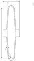
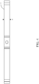
- FIGS. 3 and 4 show various geometries for flexure 122.
- flexure 122 can be configured to amplify the movement of piezo stack 140. For instance, movement of piezo stack 140 by a first amount, in the direction indicated by arrow 144 may be amplified so that it results in greater movement of flexure 122 in the direction indicated by arrow 146.
- displacement or movement of piezo stack 140, in the direction indicated by arrow 144 of approximately 90-100 micrometers results in axial displacement or movement of flexure 122, in the direction indicated by arrow 146, of 0.8-1.2 millimeters.
- the angle alpha of flexure 122 may be approximately 94°.
- the thickness b of flexure 122 may be approximately 1 millimeter, and the distance c may be approximately 23.24 millimeters.
- the measurement d may be 70.5 millimeters and the distance e (in FIG. 4 ) may be approximately 5 millimeters.
- the tolerances on the various measurements shown in FIGS. 3 and 4 may be +/- 1.0 millimeters and/or +/-0.1°. It will be noted that the geometry of the flexure 122 shown in FIGS. 3 and 4 is only one example, and others may be used as well, depending on the application, the desired valve response times, etc.
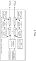
- FIG. 5 is a block diagram showing one example of a mobile agricultural application machine 200 that can use the valve assembly 100 illustrated above in FIGS. 1-4 .
- mobile agricultural application machine 200 may be an agricultural planter, an agricultural sprayer, etc.
- machine 200 can include one or more sensors 202, a set of configuration inputs 204, application control system 206, one or more sources of substance to be applied 208, 210, nozzles 212, 214 through which the substance is applied to the agricultural field, corresponding valves 216, 218 which control the application of the substance to be applied through nozzles 212 and 214, respectively.
- Machine 200 can also include one or more pressure sensors 220, 222 which sense the pressure drop across valves 216, 218 or across the nozzles or the pressure on the inlet or outlet end of the valves or nozzles, respectively, and valve position sensors 224, 226 which sense the position of valves 216, 218, respectively.
- the valve position sensors 224, 226 can be similar to sensor 136 described above with respect to FIG. 1 . They can be different sensors as well.
- FIG. 5 also shows that, in one example, machine 200 can include a wide variety of other machine functionality 228.
- Functionality 228 can include such things as operator input mechanisms and functionality so that machine 200 can be operated by an operator, a propulsion system, a steering system, various power sources and power systems, various different actuators, pumps, etc. It can also include a wide variety of other functionality as well.
- Sensors 202 can sense a wide variety of things, such as soil conditions, machine speed, machine travel direction, machine position, machine orientation, weather conditions, machine settings, machine operating conditions or parameters, etc.
- Configuration inputs 204 can include operator inputs that are used to set the application rate or pressure for the material to be applied to the agricultural field. They can also be automatically generated inputs that are generated based on control algorithms or other items to control application control system 206.
- application control system 206 receives various inputs and generates valve control signals that are output to control valves 216, 218.
- the valves control the flow of the substance to be applied 208, 210 through nozzles 212, 214.
- Pressure sensors 220 and 222 can also provide pressure signals back to application control system 206 so that application control system 206 can generate the valve control signals so that valves 216, 218 are controlled based upon the pressure drop across those valves (or across the entire valve/nozzle assembly).
- Valve position sensors 224, 226 can also generate position signals and provide those signals to application control system 206. In this way, application control system 206 can control the position of the plungers within valves 216, 218, based on any of a wide variety of criteria, such as pressure, flow, application rate, etc.
- FIG. 6 shows a block diagram of one example of application control system 206 in more detail.
- application control system 206 illustratively includes one or more processors 249, single/dual valve pulsing control logic 250, sense and spray logic 252, variable flow rate control logic 254 (which, itself, illustratively includes turn compensation logic 256 and other items 258), cleaning control logic 260, variable pressure control logic 262 (which, itself, can include nozzle/boom pressure regulation logic 268, side hill pressure compensation logic 270, turn (yaw) pressure compensation logic 272, and it can include other items 274), individual nozzle control signal generator 276, and it can include a wide variety of other items 278.
- application control system 206 receives configuration inputs 204 (shown in FIG. 5 ) to set single/dual valve pulsing control for pulsing operation of valves 216, 218.
- single valve pulsing control for instance, logic 250 may pulse a corresponding valve so that it applies the substance to be applied, only on seeds that have just been planted, or that were previously planted where the seed location is known. In such operation, pulsing control logic 250 can receive a seed sensor signal indicative of seed location and turns the valve off in between seeds which greatly conserves the amount of substance that is applied.
- logic 250 may be used to control two valves, or to control a single valve for the application of multiple different substances. By way of example, it may be that two different substances cannot be mixed prior to application, because of their physical or chemical properties. Thus, they can be individually applied by using dual valve pulsing control.
- Variable flow rate control logic 254 illustratively controls the flow rate of the substance to be applied through the valves by varying the valve position (e.g., the position of tip 128 of plunger 126 within valve housing 104).
- the flow rate can be varied, for instance, based upon the speed of machine 200.
- turn compensation logic 256 can vary the flow rate of individual nozzles, as the machine is turning. The speed and course of the machine can be determined based on sensed operator inputs or based on other sensor inputs from sensors 202. By way of example, when a sprayer turns in a field, the nozzles on the boom furthest to the outside of the turn will have a higher linear velocity relative to the surface of the ground, than those furthest inside on the turn.
- turn compensation logic 256 can use sensor inputs from sensors 202 indicating that machine 200 is turning in a certain direction. It can also obtain boom dimensions that are input or already stored. It can thus vary the flow rate through the different nozzles, along the boom, to achieve a relatively uniform application rate, even though the different nozzles are moving at different linear velocities relative to the surface of the ground. In one example, the turn down rate (the rate by which the maximum flow rate differs from the minimum flow rate) can be on the order of 20-1 using the valve assembly illustrated in the previous figures.
- Variable pressure control logic 266 illustratively uses the inputs from pressure sensors 220, 222 in order to control the valves 216, 218 to accommodate pressure control.
- nozzle/boom pressure regulation logic 268 can control the positions of the individual valves, for the individual nozzles along the boom, to accommodate for the change in pressure. By way of example, it may open the valves wider or close them more, to maintain a desired pressure across the nozzle.
- Side hill pressure compensation logic 270 can also be used to compensate the valve position for variations in pressure due to operating on a side hill. By way of example, it may be that a sprayer is operating on a side hill and therefore the inlet pressure may be higher on the downhill inlets 106 than on the uphill inlets 106. Side hill pressure compensation logic 270 can sense this and compensate for the pressure variance using valve position. In one example, logic 270 can do this by using the signals from pressure sensors 220, 222. In another example, logic 270 can receive topological a map indicating where side hills reside on the field being treated. It can also receive a geographic position signal indicating the geographic position and heading of machine 200 to determine that it is operating on a side hill. It can use a signal from a machine orientation sensor (such as an accelerometer or other sensor). All of these and other control algorithms are contemplated herein.
- a machine orientation sensor such as an accelerometer or other sensor
- Turn (yaw) pressure compensation logic 272 can also compensate for variations in inlet pressure due to the machine 200 turning around. For instance, if a sprayer is turning around, it may be that the inlet pressure on the valves on the outside of the turn may be higher than those on the inside of the turn. This can be sensed by logic 272, and logic 272 can be used to control the valve positions on the boom to compensate for that pressure variation.
- Sense and spray logic 252 can be used to sense an attribute indicative of a location where application of the substance to be applied is needed. For instance, if the substance to be applied is a herbicide, then sense and spray logic 252 may receive a sensor input from one of sensors 202 that may be a weed sensor. The weed sensor may be an optical sensor that captures an optical image ahead of a sprayer and uses image processing to identify weeds in that optical image. It can be a different sensor as well. Sense and spray logic 252 can then be used to generate a valve control signal to spray the weeds when the corresponding nozzle is over the weed. The same can be true where the substance to be applied is a fertilizer and the sensed plant to be sprayed is a crop plant.
- the location of the crop plants are sensed, (or stored from the planting or other previous operation) and when a crop plant is under the nozzle, the valve for the corresponding nozzle can be opened to apply the fertilizer, only where the plant is located.
- the same can be done with insecticide or other substances to be applied as well.
- Cleaning control logic 260 can be used to vary the valve position between on and off, at a relatively high rate of speed, in order to clean the corresponding nozzles. Because the valve is a piezo-actuated valve, this can be done at high frequencies relative to solenoid driven valves. It can thus be seen that a piezo-actuated valve can be used to provide significant advantages. It can be operated at a much higher rate than a solenoid driven valve. It can be used to accommodate a variable flow rate with a relatively high turn down ratio. It can be used, along with a pressure sensor, to generate pressure control (such as turn rate compensation and compensation for other pressure variations).
- It can be used to apply multiple different products or substances, even if they are not compatible (so that they cannot be mixed prior to application) because of the high rate at which the valve can be positioned between multiple positions. It can be used in sense and spray applications for crop plants, seeds, weeds, etc. This is also because it can be cycled on and off at a high enough frequency so that the seeds, plants and/or weeds can be recognized and the valves can be turned on and off in sufficient time to treat them as the vehicle moves along the field. It can also be used to accommodate relatively tight plunger position control. This can be used to control pressure for air induction nozzles, to control droplet size for pulse nozzles, and to improve cleaning operation.
- processors and servers include computer processors with associated memory and timing circuitry, not separately shown. They are functional parts of the systems or devices to which they belong and are activated by, and facilitate the functionality of the other components, logic or items in those systems.
- the figures show a number of blocks with functionality ascribed to each block. It will be noted that fewer blocks can be used so the functionality is performed by fewer components. Also, more blocks can be used with the functionality distributed among more components.
Landscapes
- Life Sciences & Earth Sciences (AREA)
- Engineering & Computer Science (AREA)
- Environmental Sciences (AREA)
- Zoology (AREA)
- Pest Control & Pesticides (AREA)
- Wood Science & Technology (AREA)
- Insects & Arthropods (AREA)
- Water Supply & Treatment (AREA)
- Soil Sciences (AREA)
- Mechanical Engineering (AREA)
- Health & Medical Sciences (AREA)
- General Health & Medical Sciences (AREA)
- Toxicology (AREA)
- Catching Or Destruction (AREA)
Abstract
Description
- The present description relates to applying a substance to an agricultural field. More specifically, the present description relates to a piezo actuated nozzle control valve for controlling the application of the substance to the agricultural field.
- There are a wide variety of different types of agricultural vehicles that apply a substance to an agricultural field. Such agricultural vehicles can include such things as sprayers, planters, or other vehicles.
- An agricultural sprayer, for instance, often carries a substance to be applied to a field. A boom has a plurality of controllable spray nozzles mounted thereon. The substance to be sprayed is pumped to the nozzles, along the boom, where it is sprayed or otherwise applied to the field. The substance to be applied to the field can be liquid, particulate, or another type of substance.
- Some planters also carry a substance to be applied to the field, in addition to seed that is planted. For instance, the substance to be applied may be fertilizer, or another substance that is applied as seeds are planted.
- The valves on such vehicles or machines often use solenoids to open and close the valve. Solenoids are relatively high power consumption devices. They can also be relatively slow. For instance, it may take on the order of 6-10 milliseconds to open a solenoid valve and 7-10 milliseconds to close it. Similarly, solenoid valves are often open/close valves. This means that it can be difficult to control the valve position and to hold it in any position between full open and full closed.
- The discussion above is merely provided for general background information and is not intended to be used as an aid in determining the scope of the claimed subject matter.
- A mobile agricultural application machine includes a controllable valve and nozzle through which a substance is applied to an agricultural field. The controllable valve is a piezo-actuated valve. An application control system generates valve control signals to control a piezo element on the piezo-actuated valve.
- This Summary is provided to introduce a selection of concepts in a simplified form that are further described below in the Detailed Description. This Summary is not intended to identify key features or essential features of the claimed subject matter, nor is it intended to be used as an aid in determining the scope of the claimed subject matter. The claimed subject matter is not limited to implementations that solve any or all disadvantages noted in the background.
-
-
FIG. 1 is an exploded view of on example of a piezo-actuated valve assembly that can be used on a mobile agricultural application machine. -
FIG. 2 is a pictorial illustration of one example of the piezo-actuated valve assembly. -
FIG. 3 is a side view of one example of a flexure. -
FIG. 4 is a top view of the flexure illustrated inFIG. 3 . -
FIG. 5 is a block diagram showing one example of a mobile agricultural application machine. -
FIG. 6 is a block diagram showing one example of an application control system in more detail. -
FIG. 1 is an exploded view of a portion of a piezo-actuatedvalve assembly 100 that can be carried by anozzle assembly 102. Thenozzle assembly 102 can be supported on a mobile agricultural application machine (such as on the boom of a sprayer, on a planter, etc.). In the example shown inFIG. 1 ,assembly 100 includesvalve housing 104 that has an inlet 106 (that receives the substance to be applied, under pressure) and anoutlet 108. Mounthousing 110 has afirst mounting plate 112 and asecond mounting plate 118.Assembly 100 also includesplunger 126, bellows 132,plunger mounting plate 116,flexure 122,flexure mounting bracket 130 andsensor 136. - The
valve housing 104 is illustratively mounted tomount housing 110 such that thefirst mounting plate 112 fits over, and receives, afirst end 114 ofvalve housing 104.Plunger mounting plate 116 is also illustratively mounted to thesecond mounting plate 118 so that a piezo element illustratively sits in avoid 120 offlexure 122. Theflexure 122 moves axially along anaxis 124 to driveplunger 126, also in the axial direction. Asplunger 126 moves in the axial direction, it causes movement ofplunger tip 128 into, and out of,valve housing 104, to control the flow of fluid betweeninlet 106 andoutlet 108. -
Mounting bracket 130 is fixedly attached to thesecond mounting plate 118 so that, whenflexure 122 moves axially, it drivesplunger 126, andtip 128, into and out ofvalve housing 104. Also, in the example illustrated inFIG. 1 ,plunger 126 is a "dry plunger". Bellows 132 is fixedly attached (e.g., welded) tovalve tip 128 generally atjunction 134. It is also illustratively fixedly attached tomounting plate 116. Therefore, asplunger 126, andtip 128, move in the axial direction,bellows 132 expands and contracts in the axial direction (in an accordion-like manner) to accommodate that movement, but to keepplunger 126 dry (out of contact with the substance being applied through valve housing 104). - As
plunger 126 moves in the axial direction, thetip 128 moves between a closed position, where it closes the passage betweeninlet 106 andoutlet 108, and an open position, where it opens that passage. In one example, and as is described in more detail below, the position ofplunger 126 and thustip 128, can be tightly controlled to control the flow or pressure throughvalve housing 104. Also, becauseflexure 122 is driven by a piezo element,plunger 126 can be driven between the open and closed positions very quickly. For instance, it can be driven between those positions at a rate of approximately 30-60 Hz, or faster. This is on the order of twice as fast as a solenoid valve. -
FIG. 1 also illustrates that, in one example,mounting bracket 130 can have sensor 136 (which can be an optical sensor or another sensor) disposed thereon.Sensor 136 is configured to illustratively sense the deflection offlexure 122 in the axial direction. Alternatively, it can be configured to sense the position of the piezo stack that resides invoid 122. -
FIG. 2 is a pictorial illustration of a portion of valve assembly 100 (withmounting plate 110 andmounting bracket 130 removed for the sake of clarity). The items that are similar to those shown inFIG. 1 are similarly numbered. -
FIG. 2 also schematically illustrates a piezo element in form of apiezo stack 140, positioned within thevoid 120 inflexure 122. Thepiezo stack 140 is illustratively driven by one or morevalve control signals 142. Thevalve control signals 142 are applied topiezo stack 140 so that it expands and contracts generally in the direction indicated byarrow 144. This causesflexure 122 to deflect axially, generally in the direction indicated byarrow 146, alongaxis 124. For instance, aspiezo stack 140 expands outwardly, this causesflexure 122 to contract in the axial direction (along axis 124). However, aspiezo stack 140 is controlled to contract along the axis indicated byarrow 144, this causesflexure 122 to expand in the axial direction. Because theend 141 offlexure 122 is fixed relative to valve housing 104 (bymounting bracket 130 andmount housing 110 shown inFIG. 1 ) expansion and contraction offlexure 122 in the axial direction causes reciprocating movement ofplunger 126, andplunger tip 128 relative tovalve housing 104.Bellows 132 acts as an accordion (and it can be formed of electrically formed steel or another material) so that none of the substance being applied throughvalve housing 104 comes into contact withplunger 126. -
FIG. 2 also shows another example in which anadditional inlet 150 is provided onvalve housing 104. Housing 104 can be formed so that thetip 128 ofplunger 126 can be moved between different positions. For example, in a first position, the valve is completely closed and no substance exits throughoutlet 108. In a second position, only solution frominlet 106 is provided tooutlet 108. In a third position, only solution frominlet 150 is provided tooutlet 108, and in a fourth position, the substance from bothinlets outlet 108. Any or all of these configurations are contemplated herein. In this way,piezo stack 140 can be controlled so that two different substances can be applied, at different rates, using thesingle valve housing 104. -
FIGS. 3 and4 show various geometries forflexure 122. In one example, it will be noted thatflexure 122 can be configured to amplify the movement ofpiezo stack 140. For instance, movement ofpiezo stack 140 by a first amount, in the direction indicated byarrow 144 may be amplified so that it results in greater movement offlexure 122 in the direction indicated byarrow 146. For example, in one configuration, displacement or movement ofpiezo stack 140, in the direction indicated byarrow 144 of approximately 90-100 micrometers results in axial displacement or movement offlexure 122, in the direction indicated byarrow 146, of 0.8-1.2 millimeters. In such a configuration, the angle alpha offlexure 122 may be approximately 94°. The thickness b offlexure 122 may be approximately 1 millimeter, and the distance c may be approximately 23.24 millimeters. The measurement d may be 70.5 millimeters and the distance e (inFIG. 4 ) may be approximately 5 millimeters. The tolerances on the various measurements shown inFIGS. 3 and4 may be +/- 1.0 millimeters and/or +/-0.1°. It will be noted that the geometry of theflexure 122 shown inFIGS. 3 and4 is only one example, and others may be used as well, depending on the application, the desired valve response times, etc. -
FIG. 5 is a block diagram showing one example of a mobileagricultural application machine 200 that can use thevalve assembly 100 illustrated above inFIGS. 1-4 . In the example shown inFIG. 5 , mobile agricultural application machine 200 (machine 200) may be an agricultural planter, an agricultural sprayer, etc. In the example illustrated,machine 200 can include one ormore sensors 202, a set of configuration inputs 204,application control system 206, one or more sources of substance to be applied 208, 210,nozzles valves nozzles Machine 200 can also include one ormore pressure sensors valves valve position sensors valves valve position sensors sensor 136 described above with respect toFIG. 1 . They can be different sensors as well. -
FIG. 5 also shows that, in one example,machine 200 can include a wide variety ofother machine functionality 228.Functionality 228 can include such things as operator input mechanisms and functionality so thatmachine 200 can be operated by an operator, a propulsion system, a steering system, various power sources and power systems, various different actuators, pumps, etc. It can also include a wide variety of other functionality as well. -
Sensors 202 can sense a wide variety of things, such as soil conditions, machine speed, machine travel direction, machine position, machine orientation, weather conditions, machine settings, machine operating conditions or parameters, etc. Configuration inputs 204 can include operator inputs that are used to set the application rate or pressure for the material to be applied to the agricultural field. They can also be automatically generated inputs that are generated based on control algorithms or other items to controlapplication control system 206. - In the example illustrated in
FIG. 5 ,application control system 206 receives various inputs and generates valve control signals that are output to controlvalves nozzles Pressure sensors application control system 206 so thatapplication control system 206 can generate the valve control signals so thatvalves Valve position sensors application control system 206. In this way,application control system 206 can control the position of the plungers withinvalves -
FIG. 6 shows a block diagram of one example ofapplication control system 206 in more detail. In the example shown inFIG. 6 ,application control system 206 illustratively includes one ormore processors 249, single/dual valvepulsing control logic 250, sense andspray logic 252, variable flow rate control logic 254 (which, itself, illustratively includesturn compensation logic 256 and other items 258), cleaningcontrol logic 260, variable pressure control logic 262 (which, itself, can include nozzle/boompressure regulation logic 268, side hillpressure compensation logic 270, turn (yaw)pressure compensation logic 272, and it can include other items 274), individual nozzlecontrol signal generator 276, and it can include a wide variety ofother items 278. - In one example,
application control system 206 receives configuration inputs 204 (shown inFIG. 5 ) to set single/dual valve pulsing control for pulsing operation ofvalves logic 250 may pulse a corresponding valve so that it applies the substance to be applied, only on seeds that have just been planted, or that were previously planted where the seed location is known. In such operation, pulsingcontrol logic 250 can receive a seed sensor signal indicative of seed location and turns the valve off in between seeds which greatly conserves the amount of substance that is applied. In dual valve pulsing control, for instance,logic 250 may be used to control two valves, or to control a single valve for the application of multiple different substances. By way of example, it may be that two different substances cannot be mixed prior to application, because of their physical or chemical properties. Thus, they can be individually applied by using dual valve pulsing control. - Variable flow
rate control logic 254 illustratively controls the flow rate of the substance to be applied through the valves by varying the valve position (e.g., the position oftip 128 ofplunger 126 within valve housing 104). The flow rate can be varied, for instance, based upon the speed ofmachine 200. In addition,turn compensation logic 256 can vary the flow rate of individual nozzles, as the machine is turning. The speed and course of the machine can be determined based on sensed operator inputs or based on other sensor inputs fromsensors 202. By way of example, when a sprayer turns in a field, the nozzles on the boom furthest to the outside of the turn will have a higher linear velocity relative to the surface of the ground, than those furthest inside on the turn. In that case, turncompensation logic 256 can use sensor inputs fromsensors 202 indicating thatmachine 200 is turning in a certain direction. It can also obtain boom dimensions that are input or already stored. It can thus vary the flow rate through the different nozzles, along the boom, to achieve a relatively uniform application rate, even though the different nozzles are moving at different linear velocities relative to the surface of the ground. In one example, the turn down rate (the rate by which the maximum flow rate differs from the minimum flow rate) can be on the order of 20-1 using the valve assembly illustrated in the previous figures.
Variablepressure control logic 266 illustratively uses the inputs frompressure sensors valves pressure regulation logic 268 can control the positions of the individual valves, for the individual nozzles along the boom, to accommodate for the change in pressure. By way of example, it may open the valves wider or close them more, to maintain a desired pressure across the nozzle. - Side hill
pressure compensation logic 270 can also be used to compensate the valve position for variations in pressure due to operating on a side hill. By way of example, it may be that a sprayer is operating on a side hill and therefore the inlet pressure may be higher on thedownhill inlets 106 than on theuphill inlets 106. Side hillpressure compensation logic 270 can sense this and compensate for the pressure variance using valve position. In one example,logic 270 can do this by using the signals frompressure sensors logic 270 can receive topological a map indicating where side hills reside on the field being treated. It can also receive a geographic position signal indicating the geographic position and heading ofmachine 200 to determine that it is operating on a side hill. It can use a signal from a machine orientation sensor (such as an accelerometer or other sensor). All of these and other control algorithms are contemplated herein. - Turn (yaw)
pressure compensation logic 272 can also compensate for variations in inlet pressure due to themachine 200 turning around. For instance, if a sprayer is turning around, it may be that the inlet pressure on the valves on the outside of the turn may be higher than those on the inside of the turn. This can be sensed bylogic 272, andlogic 272 can be used to control the valve positions on the boom to compensate for that pressure variation. - Sense and
spray logic 252 can be used to sense an attribute indicative of a location where application of the substance to be applied is needed. For instance, if the substance to be applied is a herbicide, then sense andspray logic 252 may receive a sensor input from one ofsensors 202 that may be a weed sensor. The weed sensor may be an optical sensor that captures an optical image ahead of a sprayer and uses image processing to identify weeds in that optical image. It can be a different sensor as well. Sense andspray logic 252 can then be used to generate a valve control signal to spray the weeds when the corresponding nozzle is over the weed. The same can be true where the substance to be applied is a fertilizer and the sensed plant to be sprayed is a crop plant. The location of the crop plants are sensed, (or stored from the planting or other previous operation) and when a crop plant is under the nozzle, the valve for the corresponding nozzle can be opened to apply the fertilizer, only where the plant is located. The same can be done with insecticide or other substances to be applied as well. -
Cleaning control logic 260 can be used to vary the valve position between on and off, at a relatively high rate of speed, in order to clean the corresponding nozzles. Because the valve is a piezo-actuated valve, this can be done at high frequencies relative to solenoid driven valves.
It can thus be seen that a piezo-actuated valve can be used to provide significant advantages. It can be operated at a much higher rate than a solenoid driven valve. It can be used to accommodate a variable flow rate with a relatively high turn down ratio. It can be used, along with a pressure sensor, to generate pressure control (such as turn rate compensation and compensation for other pressure variations). It can be used to apply multiple different products or substances, even if they are not compatible (so that they cannot be mixed prior to application) because of the high rate at which the valve can be positioned between multiple positions. It can be used in sense and spray applications for crop plants, seeds, weeds, etc. This is also because it can be cycled on and off at a high enough frequency so that the seeds, plants and/or weeds can be recognized and the valves can be turned on and off in sufficient time to treat them as the vehicle moves along the field. It can also be used to accommodate relatively tight plunger position control. This can be used to control pressure for air induction nozzles, to control droplet size for pulse nozzles, and to improve cleaning operation. - The present discussion has mentioned processors and servers. In one examples, the processors and servers include computer processors with associated memory and timing circuitry, not separately shown. They are functional parts of the systems or devices to which they belong and are activated by, and facilitate the functionality of the other components, logic or items in those systems.
- Also, the figures show a number of blocks with functionality ascribed to each block. It will be noted that fewer blocks can be used so the functionality is performed by fewer components. Also, more blocks can be used with the functionality distributed among more components.
Claims (16)
- A mobile agricultural application machine (200), comprising:a vehicle propulsion system;a source of a substance (208, 210) to be applied to an agricultural field;a spray nozzle (212, 214);a control signal generator (276) that generates a valve control signal (142); anda piezo-actuated valve (216, 218) that receives the valve control signal (142) and moves based on the valve control signal (142) to apply the substance (208, 210) to be applied to the agricultural field through the spray nozzle (212, 214).
- The mobile agricultural application machine (200) of claim 1 wherein the piezo-actuated valve (216, 218) comprises:a piezo element (140) configured to deform in response to application of the valve control signal (142); anda flexure (122), coupled to the piezo element (140), and configured to amplify deformation of the piezo element (140) to provide a valve driving movement.
- The mobile agricultural application machine (200) of claim 2 wherein the piezo-actuated valve (216, 218) comprises:a plunger (126) having a proximal end coupled to the flexure (122) and a distal end andconfigured to move reciprocally between a valve open position and a valve closed position as the flexure (122) moves through the valve driving movement.
- The mobile agricultural application machine (200) of claim 3 wherein the piezo-actuated valve (216, 218) comprises:a bellows (132) having a distal end coupled to the distal end of the plunger (126) with a liquid-tight connection and a proximal end fixed relative to reciprocal movement of the plunger (126).
- The mobile agricultural application machine (200) of one of the claims 1 to 4 and further comprising:a pressure sensor (220, 222) configured to sense a pressure of the substance (208, 210) to be applied and generate a pressure signal indicative of the pressure of the substance (208, 210) to be applied, wherein the control signal generator comprises:a variable pressure control logic (266) configured to generate the valve control signal (142) to control the piezo-actuated valve (216, 218) based on the pressure signal.
- The mobile agricultural application machine (200) of claim 5 wherein the spray nozzle (212, 214) comprises a plurality of different spray nozzles (212, 214), and further comprising a plurality of different piezo-actuated valves (216, 218), and, a separate pressure sensor (220, 222) corresponding to each of the plurality of different spray nozzles (212, 214), each pressure sensor (220, 222) being configured to generate a separate pressure signal.
- The mobile agricultural application machine (200) of claim 5 or 6 wherein the variable pressure control logic (266) comprises:a nozzle pressure regulation logic (268) configured to generate a separate valve control signal (142) to control each of the piezo-actuated valves (216, 218) based on the separate pressure signals.
- The mobile agricultural application machine (200) of claim 6 or 7 and further comprising a boom, wherein each of the plurality of different piezo-actuated valves (216, 218) is mounted at a different location along the boom and wherein the separate pressure sensors (220, 222) are configured to sense pressure at different locations along the boom, wherein the control signal generator (276) comprises:a boom pressure regulation logic (268) configured to generate a separate valve control signal (142) to control each of the piezo-actuated valves (216, 218) based on the separate pressure signals indicative of the pressure at different locations along the boom.
- The mobile agricultural application machine (200) of one of the claims 1 to 8 and further comprising: a boom, wherein each of the plurality of different piezo-actuated valves (216, 218) is mounted at a different position along the boom and further comprising:a turn sensor (202) configured to sense when the machine (200) is making a turn andgenerate a turn sensor signal indicative of the sensed turn; andturn pressure compensation logic (272) configured to generate a separate valve control signal (142) to control each of the piezo-actuated valves (216, 218) based on the turn signal and based on a position of each of the piezo-actuated valves (216, 218) along the boom.
- The mobile agricultural application machine (200) of one of the claims 1 to 9 and further comprising a boom, wherein each of the plurality of different piezo-actuated valves (216, 218) is mounted at a different position along the boom and further comprising:an orientation sensor (202) configured to sense an orientation of the machine (200) indicating that the machine (200) is on a side hill and generate an orientation sensor signal indicative of the sensed orientation; andside hill pressure compensation logic (270) configured to generate a separate valve control signal (142) to control each of the piezo-actuated valves (216, 218) based on the orientation signal and based on a position of each of the piezo-actuated valves (216, 218) along the boom.
- The mobile agricultural application machine (200) of one of the claims 1 to 10 wherein the spray nozzle (212, 214) comprises:a plurality of different spray nozzles (212, 214), each configured to spray a different substance (208, 210) to be applied to the agricultural field, and wherein the piezo-actuated valve (216, 218) is configured to control application of the plurality of different substances (208, 210) through the plurality of different nozzles (212, 214).
- The mobile agricultural application machine (200) of one of the claims 1 to 11 and further comprising:a flow rate sensor configured to sense a flow rate of the substance (208, 210) through the valve (216, 218), and wherein the control signal generator is configured to generate the valve control signal (142) based on the sensed flow rate.
- An agricultural spray nozzle assembly (102), comprising:a spray nozzle (212, 214); anda piezo-actuated valve (216, 218) that receives a valve control signal (142) and moves based on the valve control signal (142) to control movement of a substance (208, 210) to be applied to an agricultural field through the spray nozzle (212, 214).
- The agricultural spray nozzle assembly (102) of claim 13 and further comprising:a characteristic sensor configured to sense a characteristic of the substance (208, 210) to be applied and generate a characteristic signal indicative of the characteristic of the substance (208, 210) to be applied, wherein the characteristic sensor comprises at least one of a flow sensor sensing flow of the substance (208, 210) through the piezo-actuated valve (216, 218) or a pressure sensor (220, 222) sensing a pressure of the substance (208, 210) in the piezo-actuated valve (216, 218).
- A method of controlling a mobile agricultural machine (200) to apply a substance (208, 210) to an agricultural field, the method comprising:generating a valve control signal (142) to control an agricultural spray valve (216, 218) on the mobile agricultural machine (200); andapplying the valve control signal (142) to a piezo element (140) in the agricultural spray valve (216, 218) to control the agricultural spray valve (216, 218).
- The method of claim 15 wherein generating the valve control signal (142) comprises:sensing pressure of the substance (208, 210) in the agricultural spray valve (216, 218);generating a pressure signal indicative of the sensed pressure; andgenerating the valve control signal (142) to control the piezo element (140) in the agricultural spray valve (216, 218) on the mobile agricultural machine (200) based on the pressure signal, wherein generating the valve control signal (142) further comprises:sensing flow of the substance (208, 210) through the agricultural spray valve (216, 218);generating a flow signal indicative of the sensed flow; andgenerating the valve control signal (142) to control the piezo element (140) in the agricultural spray valve (216, 218) on the mobile agricultural machine (200) based on the flow signal.
Applications Claiming Priority (2)
| Application Number | Priority Date | Filing Date | Title |
|---|---|---|---|
| US201762593458P | 2017-12-01 | 2017-12-01 | |
| US16/145,691 US10980170B2 (en) | 2017-12-01 | 2018-09-28 | Piezo actuated nozzle control valve |
Publications (2)
| Publication Number | Publication Date |
|---|---|
| EP3491921A1 true EP3491921A1 (en) | 2019-06-05 |
| EP3491921B1 EP3491921B1 (en) | 2021-03-10 |
Family
ID=64331818
Family Applications (1)
| Application Number | Title | Priority Date | Filing Date |
|---|---|---|---|
| EP18206566.4A Active EP3491921B1 (en) | 2017-12-01 | 2018-11-15 | Mobile agricultural application machine, spray nozzle assembly and method of controlling a mobile agricultural machine |
Country Status (5)
| Country | Link |
|---|---|
| US (2) | US10980170B2 (en) |
| EP (1) | EP3491921B1 (en) |
| AU (1) | AU2018267572B2 (en) |
| CA (1) | CA3025739A1 (en) |
| DK (1) | DK3491921T3 (en) |
Families Citing this family (4)
| Publication number | Priority date | Publication date | Assignee | Title |
|---|---|---|---|---|
| US10980170B2 (en) * | 2017-12-01 | 2021-04-20 | Deere & Company | Piezo actuated nozzle control valve |
| US11071293B2 (en) * | 2018-10-08 | 2021-07-27 | Blue River Technology Inc. | Nozzles with interchangeable inserts for precision application of crop protectant |
| US12122350B2 (en) | 2021-02-22 | 2024-10-22 | Cnh Industrial America Llc | System and method for purging agricultural sprayer nozzles using air pressure data |
| CN115885958B (en) * | 2022-10-28 | 2025-09-16 | 河南农业大学 | PWM variable boom sprayer |
Citations (4)
| Publication number | Priority date | Publication date | Assignee | Title |
|---|---|---|---|---|
| US5310113A (en) * | 1992-12-01 | 1994-05-10 | Cowgur Bruce E | Sprayer control system and method for using same |
| US20130233940A1 (en) * | 2010-08-31 | 2013-09-12 | Exel Industries | Spraying Assembly, and Sprayer Equipped with at least one such Assembly |
| CN103507800A (en) * | 2013-09-29 | 2014-01-15 | 江苏理工学院 | Piezoelectric oil circuit control valve and vehicle electronic hydraulic braking system |
| US10076088B2 (en) * | 2012-06-05 | 2018-09-18 | Sa Exel Industries | Agricultural crop and field sprayer and method for controlling an agricultural crop and field sprayer |
Family Cites Families (10)
| Publication number | Priority date | Publication date | Assignee | Title |
|---|---|---|---|---|
| US4723709A (en) * | 1986-06-18 | 1988-02-09 | E. I. Du Pont De Nemours And Company | Multi-boom field sprayer |
| GB2315436B (en) * | 1996-07-24 | 2000-03-29 | Nomix Chipman Ltd | Distribution of a liquid composition |
| US5911362A (en) * | 1997-02-26 | 1999-06-15 | Dickey-John Corporation | Control system for a mobile material distribution device |
| EP1604569A4 (en) * | 2003-03-14 | 2006-10-18 | Seiko Epson Corp | CHEMICAL DIFFUSION SYSTEM, CHEMICAL DIFFUSION APPARATUS, CHEMICAL DIFFUSION UNIT AND CHEMICAL CARTILAGE |
| US20070084946A1 (en) * | 2005-10-07 | 2007-04-19 | Neville Robert E | Dual tank spray system and spreader for use therewith |
| JP2012533275A (en) | 2009-07-10 | 2012-12-20 | ヴァイキング エーティー,エルエルシー | SMART ACTUATOR DEVICE HAVING INSTALLABLE ARMS AND ENERGY ACQUIRING DEVICE |
| WO2011029081A2 (en) | 2009-09-04 | 2011-03-10 | Viking At, Llc | Smart material actuator adapted for resonant operation |
| WO2011103324A2 (en) | 2010-02-17 | 2011-08-25 | Viking At, Llc | Smart material actuator capable of operating in three dimensions |
| US8729774B2 (en) | 2010-12-09 | 2014-05-20 | Viking At, Llc | Multiple arm smart material actuator with second stage |
| US10980170B2 (en) * | 2017-12-01 | 2021-04-20 | Deere & Company | Piezo actuated nozzle control valve |
-
2018
- 2018-09-28 US US16/145,691 patent/US10980170B2/en active Active
- 2018-11-15 DK DK18206566.4T patent/DK3491921T3/en active
- 2018-11-15 EP EP18206566.4A patent/EP3491921B1/en active Active
- 2018-11-20 AU AU2018267572A patent/AU2018267572B2/en active Active
- 2018-11-29 CA CA3025739A patent/CA3025739A1/en active Pending
-
2021
- 2021-03-17 US US17/204,045 patent/US11800830B2/en active Active
Patent Citations (4)
| Publication number | Priority date | Publication date | Assignee | Title |
|---|---|---|---|---|
| US5310113A (en) * | 1992-12-01 | 1994-05-10 | Cowgur Bruce E | Sprayer control system and method for using same |
| US20130233940A1 (en) * | 2010-08-31 | 2013-09-12 | Exel Industries | Spraying Assembly, and Sprayer Equipped with at least one such Assembly |
| US10076088B2 (en) * | 2012-06-05 | 2018-09-18 | Sa Exel Industries | Agricultural crop and field sprayer and method for controlling an agricultural crop and field sprayer |
| CN103507800A (en) * | 2013-09-29 | 2014-01-15 | 江苏理工学院 | Piezoelectric oil circuit control valve and vehicle electronic hydraulic braking system |
Also Published As
| Publication number | Publication date |
|---|---|
| US11800830B2 (en) | 2023-10-31 |
| DK3491921T3 (en) | 2021-06-07 |
| US20210195831A1 (en) | 2021-07-01 |
| US10980170B2 (en) | 2021-04-20 |
| BR102018074593A2 (en) | 2019-07-30 |
| AU2018267572A1 (en) | 2019-06-20 |
| AU2018267572B2 (en) | 2024-09-26 |
| US20190166757A1 (en) | 2019-06-06 |
| CA3025739A1 (en) | 2019-06-01 |
| EP3491921B1 (en) | 2021-03-10 |
Similar Documents
| Publication | Publication Date | Title |
|---|---|---|
| US11800830B2 (en) | Piezo actuated nozzle control valve | |
| CA2798830C (en) | Sprayer pulsing nozzle flow control using rotational step positions | |
| CA3143551C (en) | Hydraulic spray nozzle | |
| US9635848B2 (en) | Spray system with speed-based pressure controller and method of controlling same | |
| US11659828B2 (en) | Systems and methods for fluid application including sectioned spray boom and section control valves for sectional pressure control | |
| US6522948B1 (en) | Agricultural product application tracking and control | |
| CA3143500C (en) | Pressure-based flow meter for a spray nozzle | |
| US11711997B2 (en) | Seed furrow liquid application systems, methods, and apparatuses | |
| CN117337135A (en) | Spot spraying methods and systems for high-precision application of pesticides | |
| CN107645909A (en) | Weeder | |
| KR102272571B1 (en) | Dispensers with sensors for sensing surface and surface properties | |
| US20230264207A1 (en) | Dynamically controllable spray nozzle, control system, and method | |
| CN110637799A (en) | A device and method for precise target application of crops with wide plant spacing based on ultrasonic sensor | |
| Butts et al. | Droplet velocity from broadcast agricultural nozzles as influenced by pulse-width modulation | |
| CN113840532A (en) | Systems, methods and apparatus for providing variable rate application of an applicator to discrete field locations | |
| Karkee et al. | 10 Automation of Pesticide Application Systems | |
| BR102018074593B1 (en) | MOBILE AGRICULTURAL APPLICATION MACHINE, AGRICULTURAL SPRAYING NOZZLE ASSEMBLY, AGRICULTURAL SPRAYING NOZZLE, AND, METHOD FOR CONTROLLING A MOBILE AGRICULTURAL MACHINE FOR APPLYING A SUBSTANCE TO AN AGRICULTURAL FIELD | |
| Vijayakumar et al. | AI-powered Autonomous Smart Sprayer for Precision Weed Management: Advancing Sustainable Agriculture Through Machine Vision, Automation, and Control Systems |
Legal Events
| Date | Code | Title | Description |
|---|---|---|---|
| PUAI | Public reference made under article 153(3) epc to a published international application that has entered the european phase |
Free format text: ORIGINAL CODE: 0009012 |
|
| STAA | Information on the status of an ep patent application or granted ep patent |
Free format text: STATUS: THE APPLICATION HAS BEEN PUBLISHED |
|
| AK | Designated contracting states |
Kind code of ref document: A1 Designated state(s): AL AT BE BG CH CY CZ DE DK EE ES FI FR GB GR HR HU IE IS IT LI LT LU LV MC MK MT NL NO PL PT RO RS SE SI SK SM TR |
|
| AX | Request for extension of the european patent |
Extension state: BA ME |
|
| STAA | Information on the status of an ep patent application or granted ep patent |
Free format text: STATUS: REQUEST FOR EXAMINATION WAS MADE |
|
| 17P | Request for examination filed |
Effective date: 20191205 |
|
| RBV | Designated contracting states (corrected) |
Designated state(s): AL AT BE BG CH CY CZ DE DK EE ES FI FR GB GR HR HU IE IS IT LI LT LU LV MC MK MT NL NO PL PT RO RS SE SI SK SM TR |
|
| GRAP | Despatch of communication of intention to grant a patent |
Free format text: ORIGINAL CODE: EPIDOSNIGR1 |
|
| STAA | Information on the status of an ep patent application or granted ep patent |
Free format text: STATUS: GRANT OF PATENT IS INTENDED |
|
| RIC1 | Information provided on ipc code assigned before grant |
Ipc: A01M 21/04 20060101ALI20201028BHEP Ipc: A01M 7/00 20060101AFI20201028BHEP |
|
| INTG | Intention to grant announced |
Effective date: 20201119 |
|
| RIN1 | Information on inventor provided before grant (corrected) |
Inventor name: HUMPAL, RICHARD A Inventor name: MERCER, DAVID S |
|
| GRAS | Grant fee paid |
Free format text: ORIGINAL CODE: EPIDOSNIGR3 |
|
| GRAA | (expected) grant |
Free format text: ORIGINAL CODE: 0009210 |
|
| STAA | Information on the status of an ep patent application or granted ep patent |
Free format text: STATUS: THE PATENT HAS BEEN GRANTED |
|
| AK | Designated contracting states |
Kind code of ref document: B1 Designated state(s): AL AT BE BG CH CY CZ DE DK EE ES FI FR GB GR HR HU IE IS IT LI LT LU LV MC MK MT NL NO PL PT RO RS SE SI SK SM TR |
|
| REG | Reference to a national code |
Ref country code: GB Ref legal event code: FG4D |
|
| REG | Reference to a national code |
Ref country code: CH Ref legal event code: EP Ref country code: AT Ref legal event code: REF Ref document number: 1368757 Country of ref document: AT Kind code of ref document: T Effective date: 20210315 |
|
| REG | Reference to a national code |
Ref country code: IE Ref legal event code: FG4D |
|
| REG | Reference to a national code |
Ref country code: DE Ref legal event code: R096 Ref document number: 602018013676 Country of ref document: DE |
|
| REG | Reference to a national code |
Ref country code: NL Ref legal event code: FP |
|
| REG | Reference to a national code |
Ref country code: DK Ref legal event code: T3 Effective date: 20210603 |
|
| REG | Reference to a national code |
Ref country code: LT Ref legal event code: MG9D |
|
| PG25 | Lapsed in a contracting state [announced via postgrant information from national office to epo] |
Ref country code: LT Free format text: LAPSE BECAUSE OF FAILURE TO SUBMIT A TRANSLATION OF THE DESCRIPTION OR TO PAY THE FEE WITHIN THE PRESCRIBED TIME-LIMIT Effective date: 20210310 Ref country code: NO Free format text: LAPSE BECAUSE OF FAILURE TO SUBMIT A TRANSLATION OF THE DESCRIPTION OR TO PAY THE FEE WITHIN THE PRESCRIBED TIME-LIMIT Effective date: 20210610 Ref country code: BG Free format text: LAPSE BECAUSE OF FAILURE TO SUBMIT A TRANSLATION OF THE DESCRIPTION OR TO PAY THE FEE WITHIN THE PRESCRIBED TIME-LIMIT Effective date: 20210610 Ref country code: HR Free format text: LAPSE BECAUSE OF FAILURE TO SUBMIT A TRANSLATION OF THE DESCRIPTION OR TO PAY THE FEE WITHIN THE PRESCRIBED TIME-LIMIT Effective date: 20210310 Ref country code: GR Free format text: LAPSE BECAUSE OF FAILURE TO SUBMIT A TRANSLATION OF THE DESCRIPTION OR TO PAY THE FEE WITHIN THE PRESCRIBED TIME-LIMIT Effective date: 20210611 Ref country code: FI Free format text: LAPSE BECAUSE OF FAILURE TO SUBMIT A TRANSLATION OF THE DESCRIPTION OR TO PAY THE FEE WITHIN THE PRESCRIBED TIME-LIMIT Effective date: 20210310 |
|
| REG | Reference to a national code |
Ref country code: AT Ref legal event code: MK05 Ref document number: 1368757 Country of ref document: AT Kind code of ref document: T Effective date: 20210310 |
|
| PG25 | Lapsed in a contracting state [announced via postgrant information from national office to epo] |
Ref country code: RS Free format text: LAPSE BECAUSE OF FAILURE TO SUBMIT A TRANSLATION OF THE DESCRIPTION OR TO PAY THE FEE WITHIN THE PRESCRIBED TIME-LIMIT Effective date: 20210310 Ref country code: LV Free format text: LAPSE BECAUSE OF FAILURE TO SUBMIT A TRANSLATION OF THE DESCRIPTION OR TO PAY THE FEE WITHIN THE PRESCRIBED TIME-LIMIT Effective date: 20210310 Ref country code: SE Free format text: LAPSE BECAUSE OF FAILURE TO SUBMIT A TRANSLATION OF THE DESCRIPTION OR TO PAY THE FEE WITHIN THE PRESCRIBED TIME-LIMIT Effective date: 20210310 |
|
| PG25 | Lapsed in a contracting state [announced via postgrant information from national office to epo] |
Ref country code: SM Free format text: LAPSE BECAUSE OF FAILURE TO SUBMIT A TRANSLATION OF THE DESCRIPTION OR TO PAY THE FEE WITHIN THE PRESCRIBED TIME-LIMIT Effective date: 20210310 Ref country code: AT Free format text: LAPSE BECAUSE OF FAILURE TO SUBMIT A TRANSLATION OF THE DESCRIPTION OR TO PAY THE FEE WITHIN THE PRESCRIBED TIME-LIMIT Effective date: 20210310 Ref country code: CZ Free format text: LAPSE BECAUSE OF FAILURE TO SUBMIT A TRANSLATION OF THE DESCRIPTION OR TO PAY THE FEE WITHIN THE PRESCRIBED TIME-LIMIT Effective date: 20210310 Ref country code: EE Free format text: LAPSE BECAUSE OF FAILURE TO SUBMIT A TRANSLATION OF THE DESCRIPTION OR TO PAY THE FEE WITHIN THE PRESCRIBED TIME-LIMIT Effective date: 20210310 |
|
| PG25 | Lapsed in a contracting state [announced via postgrant information from national office to epo] |
Ref country code: IS Free format text: LAPSE BECAUSE OF FAILURE TO SUBMIT A TRANSLATION OF THE DESCRIPTION OR TO PAY THE FEE WITHIN THE PRESCRIBED TIME-LIMIT Effective date: 20210710 Ref country code: PT Free format text: LAPSE BECAUSE OF FAILURE TO SUBMIT A TRANSLATION OF THE DESCRIPTION OR TO PAY THE FEE WITHIN THE PRESCRIBED TIME-LIMIT Effective date: 20210712 Ref country code: PL Free format text: LAPSE BECAUSE OF FAILURE TO SUBMIT A TRANSLATION OF THE DESCRIPTION OR TO PAY THE FEE WITHIN THE PRESCRIBED TIME-LIMIT Effective date: 20210310 Ref country code: RO Free format text: LAPSE BECAUSE OF FAILURE TO SUBMIT A TRANSLATION OF THE DESCRIPTION OR TO PAY THE FEE WITHIN THE PRESCRIBED TIME-LIMIT Effective date: 20210310 Ref country code: SK Free format text: LAPSE BECAUSE OF FAILURE TO SUBMIT A TRANSLATION OF THE DESCRIPTION OR TO PAY THE FEE WITHIN THE PRESCRIBED TIME-LIMIT Effective date: 20210310 |
|
| REG | Reference to a national code |
Ref country code: DE Ref legal event code: R097 Ref document number: 602018013676 Country of ref document: DE |
|
| PLBE | No opposition filed within time limit |
Free format text: ORIGINAL CODE: 0009261 |
|
| STAA | Information on the status of an ep patent application or granted ep patent |
Free format text: STATUS: NO OPPOSITION FILED WITHIN TIME LIMIT |
|
| PG25 | Lapsed in a contracting state [announced via postgrant information from national office to epo] |
Ref country code: ES Free format text: LAPSE BECAUSE OF FAILURE TO SUBMIT A TRANSLATION OF THE DESCRIPTION OR TO PAY THE FEE WITHIN THE PRESCRIBED TIME-LIMIT Effective date: 20210310 Ref country code: AL Free format text: LAPSE BECAUSE OF FAILURE TO SUBMIT A TRANSLATION OF THE DESCRIPTION OR TO PAY THE FEE WITHIN THE PRESCRIBED TIME-LIMIT Effective date: 20210310 |
|
| 26N | No opposition filed |
Effective date: 20211213 |
|
| PG25 | Lapsed in a contracting state [announced via postgrant information from national office to epo] |
Ref country code: SI Free format text: LAPSE BECAUSE OF FAILURE TO SUBMIT A TRANSLATION OF THE DESCRIPTION OR TO PAY THE FEE WITHIN THE PRESCRIBED TIME-LIMIT Effective date: 20210310 |
|
| PG25 | Lapsed in a contracting state [announced via postgrant information from national office to epo] |
Ref country code: IT Free format text: LAPSE BECAUSE OF FAILURE TO SUBMIT A TRANSLATION OF THE DESCRIPTION OR TO PAY THE FEE WITHIN THE PRESCRIBED TIME-LIMIT Effective date: 20210310 |
|
| PG25 | Lapsed in a contracting state [announced via postgrant information from national office to epo] |
Ref country code: IS Free format text: LAPSE BECAUSE OF FAILURE TO SUBMIT A TRANSLATION OF THE DESCRIPTION OR TO PAY THE FEE WITHIN THE PRESCRIBED TIME-LIMIT Effective date: 20210710 |
|
| PG25 | Lapsed in a contracting state [announced via postgrant information from national office to epo] |
Ref country code: MC Free format text: LAPSE BECAUSE OF FAILURE TO SUBMIT A TRANSLATION OF THE DESCRIPTION OR TO PAY THE FEE WITHIN THE PRESCRIBED TIME-LIMIT Effective date: 20210310 |
|
| REG | Reference to a national code |
Ref country code: CH Ref legal event code: PL |
|
| PG25 | Lapsed in a contracting state [announced via postgrant information from national office to epo] |
Ref country code: LU Free format text: LAPSE BECAUSE OF NON-PAYMENT OF DUE FEES Effective date: 20211115 Ref country code: BE Free format text: LAPSE BECAUSE OF NON-PAYMENT OF DUE FEES Effective date: 20211130 |
|
| REG | Reference to a national code |
Ref country code: BE Ref legal event code: MM Effective date: 20211130 |
|
| PG25 | Lapsed in a contracting state [announced via postgrant information from national office to epo] |
Ref country code: LI Free format text: LAPSE BECAUSE OF NON-PAYMENT OF DUE FEES Effective date: 20211130 Ref country code: CH Free format text: LAPSE BECAUSE OF NON-PAYMENT OF DUE FEES Effective date: 20211130 |
|
| PG25 | Lapsed in a contracting state [announced via postgrant information from national office to epo] |
Ref country code: IE Free format text: LAPSE BECAUSE OF NON-PAYMENT OF DUE FEES Effective date: 20211115 |
|
| PG25 | Lapsed in a contracting state [announced via postgrant information from national office to epo] |
Ref country code: CY Free format text: LAPSE BECAUSE OF FAILURE TO SUBMIT A TRANSLATION OF THE DESCRIPTION OR TO PAY THE FEE WITHIN THE PRESCRIBED TIME-LIMIT Effective date: 20210310 |
|
| PG25 | Lapsed in a contracting state [announced via postgrant information from national office to epo] |
Ref country code: HU Free format text: LAPSE BECAUSE OF FAILURE TO SUBMIT A TRANSLATION OF THE DESCRIPTION OR TO PAY THE FEE WITHIN THE PRESCRIBED TIME-LIMIT; INVALID AB INITIO Effective date: 20181115 |
|
| PG25 | Lapsed in a contracting state [announced via postgrant information from national office to epo] |
Ref country code: MK Free format text: LAPSE BECAUSE OF FAILURE TO SUBMIT A TRANSLATION OF THE DESCRIPTION OR TO PAY THE FEE WITHIN THE PRESCRIBED TIME-LIMIT Effective date: 20210310 |
|
| PG25 | Lapsed in a contracting state [announced via postgrant information from national office to epo] |
Ref country code: MT Free format text: LAPSE BECAUSE OF FAILURE TO SUBMIT A TRANSLATION OF THE DESCRIPTION OR TO PAY THE FEE WITHIN THE PRESCRIBED TIME-LIMIT Effective date: 20210310 |
|
| PG25 | Lapsed in a contracting state [announced via postgrant information from national office to epo] |
Ref country code: TR Free format text: LAPSE BECAUSE OF FAILURE TO SUBMIT A TRANSLATION OF THE DESCRIPTION OR TO PAY THE FEE WITHIN THE PRESCRIBED TIME-LIMIT Effective date: 20210310 |
|
| PGFP | Annual fee paid to national office [announced via postgrant information from national office to epo] |
Ref country code: NL Payment date: 20251126 Year of fee payment: 8 |
|
| PGFP | Annual fee paid to national office [announced via postgrant information from national office to epo] |
Ref country code: DE Payment date: 20251021 Year of fee payment: 8 |
|
| PGFP | Annual fee paid to national office [announced via postgrant information from national office to epo] |
Ref country code: GB Payment date: 20251127 Year of fee payment: 8 |
|
| PGFP | Annual fee paid to national office [announced via postgrant information from national office to epo] |
Ref country code: DK Payment date: 20251125 Year of fee payment: 8 |
|
| PGFP | Annual fee paid to national office [announced via postgrant information from national office to epo] |
Ref country code: FR Payment date: 20251125 Year of fee payment: 8 |