EP3491914A1 - Carrier for receiving thin mats with crop units rooted therein, and device and method for cultivating one or more crop units - Google Patents
Carrier for receiving thin mats with crop units rooted therein, and device and method for cultivating one or more crop units Download PDFInfo
- Publication number
- EP3491914A1 EP3491914A1 EP17001955.8A EP17001955A EP3491914A1 EP 3491914 A1 EP3491914 A1 EP 3491914A1 EP 17001955 A EP17001955 A EP 17001955A EP 3491914 A1 EP3491914 A1 EP 3491914A1
- Authority
- EP
- European Patent Office
- Prior art keywords
- carrier
- mat
- crop
- lid
- mats
- Prior art date
- Legal status (The legal status is an assumption and is not a legal conclusion. Google has not performed a legal analysis and makes no representation as to the accuracy of the status listed.)
- Granted
Links
Images



Classifications
-
- A—HUMAN NECESSITIES
- A01—AGRICULTURE; FORESTRY; ANIMAL HUSBANDRY; HUNTING; TRAPPING; FISHING
- A01G—HORTICULTURE; CULTIVATION OF VEGETABLES, FLOWERS, RICE, FRUIT, VINES, HOPS OR SEAWEED; FORESTRY; WATERING
- A01G31/00—Soilless cultivation, e.g. hydroponics
Definitions
- the present invention relates to a device and a method for cultivating one or more crop units. This device and method are particularly intended for application in the so called cultivation on water.
- Cultivation on water is used, among other things, for leaf crops that lend themselves thereto, such as certain vegetables, including lettuce, and certain herbs, including basil.
- a known method for simultaneously cultivating multiple crop units by means of cultivation on water comprises providing a carrier with a plurality of openings, and arranging in each opening thereof a plug of potting soil having therein a developing root system of a crop unit to be cultivated.
- the carrier with a number of plugs therein is place in a unit environment such as a water bath in which the carrier comes to float, or a container with an eb/flood regime, in which the carrier is moistened and becomes dry again in alternating manner. Due to the humid environment, the root systems in the plugs stimulated to develop themselves further to a large extend outside the plugs, in order to eventually be able to absorb water directly from the environment of the carrier.
- plugs from potting compost or an other loose substrate, which plugs are kept together by a root system developing itself has various disadvantages.
- the root system in the plug has not developed sufficiently, such plug can disintegrate when it is handled, such as for instance in the case of removing such plug from a seed or cutting tray. This can cause a water bath to become soiled, so that, among other things, germs present in the substrate could contaminate crop units to be cultivated.
- the disintegration of a plug could cause different plugs to obtain different dimensions, and thus to sit in the openings of a carrier under different conditions, such as at different distances to a water level provided. This may disadvantageously affect the uniformity of different crop units to be cultivated.
- plugs from loose substrate are always relatively large by themselves, because a certain volume of substrate that is offered to germinating seed or to a cutting must have certain minimum dimensions and/or ratios in order to allow a developing root system to grow in such manner that it can eventually keep together, as least substantially, the amount of substrate offered in order to form a substantially integral unit with the substrate.
- the size of a plug may however be advantageous in conjunction with the time a root system needs to develop sufficiently in order to be able to keep together a plug from loose substrate, in order to be able to, for example, be transplanted from a seed or cutting tray to a carrier.
- An object of the present invention is to provide a device and a method for cultivating one or crop units, which each are improved with respect to existing devices and methods.
- it is an object to provide a device and a method which are relatively clean, and thus give little chance of contamination of crop units with germs, and which ensure a relatively large uniformity of cultivated crop units, with relatively little loss.
- a further object to provide a device and a method which enable a relatively short cultivation time.
- a mat from a certain material has, by itself, a certain integrity, which a loose substrate has not have.
- a mat from a certain material will therefore not disintegrate, or in any case less quickly, as compared to a plug from a loose substrate.
- a relatively large extend of uniformity is ensured when cultivating multiple crop units.
- a mat from a certain material does not comprise any germs, so that the chances on contamination of crop units via a water bath are reduced.
- germinating seed or a cutting of a crop unit to be cultivated will root throughout the mat relatively fast, so that the crop units to be cultivated can be transplanted from a seed or cutting tray to a carrier relatively quickly.
- the root system of a developing crop unit placed on a carrier will also relatively quickly reach to the volume of water offered, so that crop unit can be harvested relatively quickly.
- a thickness of the mat is smaller than a diameter thereof.
- a mat as intended here can also be indicated as a piece of cloth.
- the certain material preferably comprises capillary material, so that among other things the mat can serve to provide moisture to germinating seed of a crop to be cultivated.
- the certain material comprises fibre material.
- a maximum water saturation degree of the mat can be set, so that rotting of the developing crops can be counteracted.
- the fibre material may be non-woven, in order to have the mat being penetrable relatively easy for a developing root system.
- nonwoven in any case a condition is meant in which the present fibres cohere with each other only loosely, or fluffy, so that the whole of fibres is relatively airy, and fibres still can shift somewhat with respect to each other without the mat or the piece of cloth falling apart.
- Such coherence of fibres is for instance known from cloth which are known under phrase “flooding mat", which are spread on a supporting surface to place crop in pots, in order to be able to keep these crops wet by keeping the cloth wet.
- the carrier is provided with one or more openings, wherein the mat covers one or more openings.
- a carrier makes it possible to cultivate a crop unit above a quantity of water, or to place an already cultivated crop unit after cultivation on a reservoir with a volume of water, in order to be able to provide with it water and nutrients via the reservoir upon further handling and transport.
- the root system of a crop unit can then extend from the lower side of the mat downwards into a supplied amount of water in the reservoir, or only extract moisture from the mat, when this is wetted with water from the reservoir by means of condensation. Such a process allows that the mat does not have to be in direct contact with a supplied amount of water.
- the carrier may have a recessed portion, said one or more openings being provided at the bottom of the recessed portion. This makes it possible to water a crop unit supported by the carrier by pouring it into the recessed portion.
- an additional opening is provided in the carrier, which is left uncovered by the mat.
- an additional opening can function as a vent hole, to allow watering through said one or more openings and via the mat, or as a hole for aerating the water volume.
- the device may comprise a means for sealing the additional opening, to prevent leakage of water from a reservoir through the additional opening, as well as to prevent possible leakage via the mat and aforementioned openings, by maintaining an airtight closure of a reservoir.
- the carrier may have a circumferential wall which extends over a certain height above the mat, for laterally supporting a crop rooting in the mat.
- the carrier Adjacent, or around the recessed portion, the carrier may have a part that runs towards the recessed portion, for sprinkling with water and letting this run away towards the recessed portion.
- the mat may be fixed to the carrier, for example by ultrasonic welding. In this way it can be prevented that the mat comes loose from the carrier, when the mat is arranged on the top side of the carrier and the carrier is tilted, or it can be made possible that the mat is mounted on the underside of the carrier.
- the mat is fittingly shaped to be arranged in a recessed portion as previously mentioned.
- the mat can be supported by a bottom of the recessed portion, in which said one or more openings are provided, or be supported by beams extending in between different openings present.
- the carrier comprises a lid for a beaker.
- a lid makes it possible to cultivate a crop unit on a beaker with a quantity of water, or to place an already cultivated crop unit on a beaker after being raised, so that via the beaker it can be provided with water and nutrients on further handling and transport, and so that a crop unit raised on water can also be offered on water to a consumer.
- the carrier may also comprise an element having a plurality of arrangement locations for receiving therein always a medium for allowing individual crop units to be rooted therein, which element is intended for placement in a humid environment, such as in a water bath, for growing a plurality of crop units at the same time.
- a device may comprise an element having a plurality of arrangement locations, each of which is adapted to receive a carrier as defined in the foregoing.
- Several crop units can then be simultaneously cultivated on a common "grow-up element", and then be treated separately from each other after the cultivation, for example to place each crop unit on its own reservoir with a volume of water by means of its carrier.
- a mat can be held in place with respect to a support by a part that clamps against, locks onto, or otherwise fixes on the carrier. In this way a relatively thin and thus flexible mat is prevented from being released from the carrier when, for example, a crop has not yet grown to the support with its roots.
- a part which, for keeping the mat in place, can be fixed on, or can otherwise be positioned relative to, the carrier can be fixed to the mat, or at least hold the mat, so as to form a kind of frame or support for the mat. matt, and to make the relatively small, thin and flexible mat easily manageable, for example when removing the mat from a seeding or cutting tray, and transplanting the mat with a slightly developed crop unit thereon to a carrier.
- a part as mentioned may comprise an annular portion, in order to be able to extend along a circumference of the mat.
- the part may further have a protruding arm or lip to serve as a handle when handling the part and a possibly attached mat with a possible crop thereon, when placing or removing the part into or out of a sowing or cutting tray, and placing the part or an assembly of said part and a mat into or out of a carrier or removing this.
- a part where the mat is attached to, or which holds the mat, and which makes it manageable for placement in a carrier, is also called "holder" in the context of this application.
- a method according to the invention may in any case comprise one or more of the following steps:
- any volume of water present preferably reaches no further than at some distance below the carrier, or at least not up to a possibly present mat, so that a mat supported by the carrier is free of direct contact with the water volume.
- a device 1 for growing a crop unit comprises a medium 30 in which the plant unit can root, and a carrier 10 for the medium 30.
- the medium 30 comprises a mat 31 of non-woven fiber material with capillary properties.
- the mat 31 in the shown embodiment is flat, round, and relatively thin.
- the carrier 10 has a recessed portion 12, in which the mat 31 can be arranged, with a bottom 15 for supporting the mat 31.
- a bottom 15 for supporting the mat 31.
- openings are provided (not visible in Figure 1 ), which are covered by the mat 31 when that mat 31 is arranged in the recessed portion 12.
- the carrier 10 is provided with an additional opening 13, which is left uncovered by the mat 31 when it is arranged in the recessed portion 12.
- the additional opening 13 can be closed with a separate cap 40.
- the means can also be provided, which can be arranged to close off the additional opening 13, which means may possibly be stuck to the carrier 10, so that it can not be lost.
- the means may comprise a tab that is to be bent to engage the additional opening 13 to seal it.
- the recessed portion 12 has a circumferential wall 14, which, in the case of a mat 31 placed at the bottom 15, extends over at least a certain height above the mat 31.
- the carrier 10 Around the recessed portion 12, adjacent to the peripheral wall 14, the carrier 10 has a portion 16 which runs towards the recessed portion 12.
- the circumferential wall 14 and the descending portion 16 thus form a funnel-shaped whole 14, 16 in the embodiment shown.
- the mat 31 is separate from the support 10, although the mat 31 can also be fixed to the support 10 within the invention, for example by being welded thereto.
- the recessed portion 12 has a round cross-section, so that the mat 31, which in the embodiment shown is round as well, can be received in the recessed portion 12.
- the device 1 further comprises a beaker 20, while the carrier 10 is formed as a lid which can be placed on that beaker.
- the carrier 10 has for this purpose a snap edge 17, which can be snapped onto a cooperating edge 21 of the cup 20.
- the carrier 10 is placed on the beaker 20 as a lid, wherein the mat 31 is arranged in the recessed portion 12 of the lid-shaped carrier 10, and wherein the additional opening 13 is closed by the cap.
- the beaker 20 in the state of FIG. 2 is substantially air-tight and water-tight, by at least along the co-operating edges 17, 21 an air-tight and watertight closure of the lid-shaped carrier 10 on the beaker 20, an air-tight and watertight closure of the cap 40 on the additional opening 13, and an obstruction to the passage of water and air through said openings in the bottom of the lid-like carrier 10, which is caused by sealing of that openings by the mat 31.
- the assembly 1 of Fig. 2 is therefore virtually leak-proof, even when it falls over or is kept upside down, and water from the cup 20 reaches the carrier 10.
- a holder 50 can be provided for securing the mat 31 in or on a carrier 10.
- the holder 50 comprises an annular base portion 51, which is formed to secure itself against the circumferential wall 14 of the recessed portion 12 of a carrier 10 as shown in Figure 1 .
- the mat 31 is thus confined with respect to the carrier 10, in order to be held against the bottom 15.
- the mat 31 can also be fixed to the holder 50, and in particular to the ring-shaped base part 51, so that it is also secured by itself on the carrier 10 by securing the holder 50, and together with the holder 50 manageable.
- an annular section 52 is provided with an projecting arm 52, which can serve as a handle
- a device 200 comprises a carrier 210 with a plurality of openings 220, each of which is adapted to receive a mat 31, or at least an assembly of a mat 31 and a holder 50, to be able to serve as support for a plurality of mats 31, for instance during germination of seed which can be provided on each of the mats 31 in order to cultivate a crop unit on each of the set-up locations formed by the openings 220.
- the carrier 210 can be placed in a humid environment.
- the carrier 210 shown serves in such a case as what is known under the term "seed or cutting tray".
- a device 100 can also comprise a carrier, or culture element 110, with openings 120 which form set-up locations for crop units to be cultivated, and which for this purpose each are arranged to receive a mat 31 or an assembly of a holder 50 and a mat 31, with a crop unit at a certain development stage on each mat 31, said openings 120 being further apart than the openings 220 of a seeding or cutting tray 210.
- a carrier, or culture element 110 can also comprise a carrier, or culture element 110, with openings 120 which form set-up locations for crop units to be cultivated, and which for this purpose each are arranged to receive a mat 31 or an assembly of a holder 50 and a mat 31, with a crop unit at a certain development stage on each mat 31, said openings 120 being further apart than the openings 220 of a seeding or cutting tray 210.
- a device 100 ' may however, in a special embodiment, also comprise an element 110', which has a plurality of set-up locations 120', which are each arranged, or at least are adapted to the shape of a carrier 10 for a mat 31 for raising an individual crop unit, with a possible holder 50 for that mat 31, so as to be able to receive a plurality of mats 31, each supported by a separate carrier 10, and each of which via their carrier 10 are supported by said element 110 '.
- This makes it possible, after the cultivation of a plurality of crop units, to handle each of these crop units separately with their carrier 10.
- each carrier 10 is advantageously formed as a lid 10 for a beaker 20 as described above, so that after cultivation on a common supporting growing element 110', cultivated crop units can each be placed on their own beaker 20, for further trading of the crop units while each crop unit remains "on water”.
- Crop units can, if desired, only be transplanted to carriers 10 supported by a common element 110' after partial cultivation or sprouting on a seed or cutting tray, by transplanting mats 31 and any containers 50 therefor.
- crop units in a given development stage can also be placed directly in a carrier 10 supported by a beaker 20, by transplanting mats 31 and any containers 50 therefor.
- Figures 6a and 6b illustrate the presence of openings 11 in the bottom 15 of the recessed portion 12 of a carrier 10 formed as a lid for a beaker.
- the openings 11 can be larger openings ( Figure 6a ) or smaller ones, such as perforations of the bottom 15 ( Figure 6b ).
- a single opening is also possible.
- the only criterion is that a mat 31 or other medium 30 can cover an opening or openings 11 in a lid 10, or at least can seal a passage present through the lid 10, possibly by filling up such a passage.
- Such a function could in principle also be fulfilled by a thicker mat, or by, for example, a rolled-up mat.
- the bottom 15 of said lid 10, or at least a mat 31 supported by said bottom 15, or otherwise carried by the carrier 10 is at some distance above the water level 61 of a water volume 60 present in the beaker 20.
- the mat 31 is in that case arranged in the lid 10 in such a way that it can be kept moist by condensation water which at the inner side of the lid 10 can run downwards, or at least along the lid 10, so as to reach the openings 11 covered by the mat.
- a so-called "wicket", or moisture-conducting element that hangs in the water volume, and which extends up to or in the mat 31, is absent.
- the roots 71 of a crop 70 rooting in the mat 31 to reach into the water volume in order to be able to provide the crop 70 with water and nutrients.
- seedlings can root in an apparatus according to the present invention during the first stage of their life, even including germination.
- a plate-shaped carrier which is provided with a plurality of through openings, and which floats in a water bath.
- Such a carrier consists in practice of a plate of polystyrene foam with light-conical holes, which are wider at the top than at the bottom.
- a holder with culture mat and rooted plant is placed in such a hole, and drops therein to a depth where the diameter of the conical hole is equal to the outside diameter of the holder.
- a substantially closed chamber is then defined, in which air is located and a humid atmosphere. This must be sufficient to allow the roots of the plant to grow further until they finally reach the water surface.
- the present invention also relates to an improvement of such a carrier.
- a problem is that the material absorbs water, and shrinks.
- the present invention proposes an improved carrier where the problems mentioned are eliminated or at least reduced.
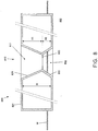
- Figure 8 shows a schematic cross-section of a portion of a plate-shaped carrier 800 according to the present invention.
- the plate-shaped carrier which may for instance have a size of 1 x 1 m 2 at a height of, for example, 5-10 cm, is formed as a hollow body, for example by blow molding, of a suitable plastic such as, for example, PVC, PE, PP.
- a suitable plastic such as, for example, PVC, PE, PP.
- the carrier 800 has two mutually parallel main surfaces 801 and 802 with a mutual distance H, which are horizontally oriented during use.
- the carrier 800 has vertical passages 810. Even if these passages are identical to the known passages, the material used already offers advantages over the presently usual Tempex.
- each passage 810 has a first conical portion 811 and a second conical portion 812.
- the first conical portion 811 has its largest diameter at the first main surface 801, while the second conical portion 812 has its largest diameter at the second main surface 802
- the respective cone-shaped side walls 821 and 822 of the two conical parts 811 and 812 meet at the narrowest part of the vertical passage 810; at this location, the vertical passage 810 is provided with an inwardly directed peripheral flange 813 formed integrally with the conical side walls 821 and 822.
- the circumferential flange 813 provides a good definition of the height at which the holder with the plant comes to stand.
- the circumferential flange 813 can lie symmetrically between the two main surfaces. In the preferred embodiment shown, this circumferential flange 813, measured in a direction perpendicular to the main surfaces 801 and 802, has a distance H1 to the first main surface 801 and a distance H2 the second main surface 802, with H2 smaller than H1.
- the plate 800 can be used in two orientations.
- the circumferential flange 813 is at a relatively short distance from the water surface. The small roots will quickly touch the water. Furthermore, as a result of adhesion to the surface of the side wall 822, the water will creep upwards and wet the material of the mat 31, as a result of which a good airtight seal of the underlying space will be achieved.
- the plate When the roots have grown further, the plate can be reversed, which effectively results in the circumferential flange 813 lying at relatively larger distance from the water surface. In addition, the space under the mat 31 becomes larger, causing more air to be available. This is favorable for further development of the roots.
- An advantage of the carrier 800 proposed by the present invention is better thermal insulation.
- the carrier 800 is substantially light-tight, in order to counteract algae growth in the space between the circumferential flange 813 and the water surface. Algae growth is competitive with root growth, and in the event of death of the algae, the water becomes too rich in nitrates.
- the light-tightness can be achieved by making the carrier of black plastic material, but this has the disadvantage that the carrier heats up relatively quickly.
- the material is preferably of a very light color, preferably white.
- light plastics have the disadvantage that the free path length of photons therein is longer, so that it is necessary to make the carrier of thicker material, but this has the disadvantage that the carrier becomes relatively heavy.
- the material of the support 800 may have a two-layer or multilayer structure, wherein the outer layer is white, and wherein a deeper layer is black.
- a white plastic for example a PVC, PE, PP to which TiO 2 -based pigment has been added, and to add small light-blocking particles to the plastic material.
- these particles When the dimensions of these particles are sufficiently small, these particles remain suspended in the liquid phase of the plastic. As the concentration of these particles increases, they will jointly block an ever increasing percentage of the transmitted light. Thanks to this aspect of the present invention, it is possible to achieve the same degree of light attenuation at a smaller material thickness, which saves material, saves material costs, and makes the carriers 800 easier to handle.
Landscapes
- Life Sciences & Earth Sciences (AREA)
- Environmental Sciences (AREA)
- Cultivation Receptacles Or Flower-Pots, Or Pots For Seedlings (AREA)
Abstract
Description
- The present invention relates to a device and a method for cultivating one or more crop units. This device and method are particularly intended for application in the so called cultivation on water.
- In the case of cultivation on water, crop units are cultivated using as little substrate as possible, such as potting soil or soil. In this melf cultivation, nutritions are largely supplied via water that is offered to a crop unit to be cultivated to be taken up by the roots thereof.
- Cultivation on water is used, among other things, for leaf crops that lend themselves thereto, such as certain vegetables, including lettuce, and certain herbs, including basil.
- A known method for simultaneously cultivating multiple crop units by means of cultivation on water comprises providing a carrier with a plurality of openings, and arranging in each opening thereof a plug of potting soil having therein a developing root system of a crop unit to be cultivated. The carrier with a number of plugs therein is place in a unit environment such as a water bath in which the carrier comes to float, or a container with an eb/flood regime, in which the carrier is moistened and becomes dry again in alternating manner. Due to the humid environment, the root systems in the plugs stimulated to develop themselves further to a large extend outside the plugs, in order to eventually be able to absorb water directly from the environment of the carrier.
- The use of plugs from potting compost or an other loose substrate, which plugs are kept together by a root system developing itself has various disadvantages. For instance, when the root system in the plug has not developed sufficiently, such plug can disintegrate when it is handled, such as for instance in the case of removing such plug from a seed or cutting tray. This can cause a water bath to become soiled, so that, among other things, germs present in the substrate could contaminate crop units to be cultivated. Also, the disintegration of a plug could cause different plugs to obtain different dimensions, and thus to sit in the openings of a carrier under different conditions, such as at different distances to a water level provided. This may disadvantageously affect the uniformity of different crop units to be cultivated. Again another disadvantage is that plugs from loose substrate are always relatively large by themselves, because a certain volume of substrate that is offered to germinating seed or to a cutting must have certain minimum dimensions and/or ratios in order to allow a developing root system to grow in such manner that it can eventually keep together, as least substantially, the amount of substrate offered in order to form a substantially integral unit with the substrate. The size of a plug may however be advantageous in conjunction with the time a root system needs to develop sufficiently in order to be able to keep together a plug from loose substrate, in order to be able to, for example, be transplanted from a seed or cutting tray to a carrier.
- An object of the present invention is to provide a device and a method for cultivating one or crop units, which each are improved with respect to existing devices and methods. In particularly, it is an object to provide a device and a method which are relatively clean, and thus give little chance of contamination of crop units with germs, and which ensure a relatively large uniformity of cultivated crop units, with relatively little loss. A further object to provide a device and a method which enable a relatively short cultivation time.
- Some of the above objectives are attained with:
- device for cultivating at least one crop unit, comprising per plant unit a separate medium for rooting the crop unit therein, and one or more carriers for the different media, wherein each medium comprises a relatively thin mat of a certain material;
- a method for growing at least one crop unit, comprising the step of providing one or more carriers for a medium for allowing a crop unit to be rooted therein, and providing the one or more carriers with a relatively thin mat of a specific material per crop unit.
- A mat from a certain material has, by itself, a certain integrity, which a loose substrate has not have. A mat from a certain material will therefore not disintegrate, or in any case less quickly, as compared to a plug from a loose substrate. Partly due to this, a relatively large extend of uniformity is ensured when cultivating multiple crop units. Different as in the case of potting compost, a mat from a certain material does not comprise any germs, so that the chances on contamination of crop units via a water bath are reduced. Because the mat is relatively thin, germinating seed or a cutting of a crop unit to be cultivated will root throughout the mat relatively fast, so that the crop units to be cultivated can be transplanted from a seed or cutting tray to a carrier relatively quickly. Caused by this, the root system of a developing crop unit placed on a carrier will also relatively quickly reach to the volume of water offered, so that crop unit can be harvested relatively quickly.
- In this context the phrase "relatively thin" is also to be understood as meaning that a thickness of the mat is smaller than a diameter thereof. In view of the relatively small thickness, a mat as intended here can also be indicated as a piece of cloth.
- The certain material preferably comprises capillary material, so that among other things the mat can serve to provide moisture to germinating seed of a crop to be cultivated.
- Preferably, the certain material comprises fibre material. By selecting a certain kind of fibre among other things a maximum water saturation degree of the mat can be set, so that rotting of the developing crops can be counteracted.
- The fibre material may be non-woven, in order to have the mat being penetrable relatively easy for a developing root system. With the phrase "nonwoven" in any case a condition is meant in which the present fibres cohere with each other only loosely, or fluffy, so that the whole of fibres is relatively airy, and fibres still can shift somewhat with respect to each other without the mat or the piece of cloth falling apart. Such coherence of fibres is for instance known from cloth which are known under phrase "flooding mat", which are spread on a supporting surface to place crop in pots, in order to be able to keep these crops wet by keeping the cloth wet.
- In an advantageous embodiment, the carrier is provided with one or more openings, wherein the mat covers one or more openings. Such a carrier makes it possible to cultivate a crop unit above a quantity of water, or to place an already cultivated crop unit after cultivation on a reservoir with a volume of water, in order to be able to provide with it water and nutrients via the reservoir upon further handling and transport. The root system of a crop unit can then extend from the lower side of the mat downwards into a supplied amount of water in the reservoir, or only extract moisture from the mat, when this is wetted with water from the reservoir by means of condensation. Such a process allows that the mat does not have to be in direct contact with a supplied amount of water.
- The carrier may have a recessed portion, said one or more openings being provided at the bottom of the recessed portion. This makes it possible to water a crop unit supported by the carrier by pouring it into the recessed portion.
- Preferably, an additional opening is provided in the carrier, which is left uncovered by the mat. When the carrier is furthermore placed on a reservoir in air-tight and watertight manner, such an additional opening can function as a vent hole, to allow watering through said one or more openings and via the mat, or as a hole for aerating the water volume.
- The device may comprise a means for sealing the additional opening, to prevent leakage of water from a reservoir through the additional opening, as well as to prevent possible leakage via the mat and aforementioned openings, by maintaining an airtight closure of a reservoir.
- The carrier may have a circumferential wall which extends over a certain height above the mat, for laterally supporting a crop rooting in the mat.
- Adjacent, or around the recessed portion, the carrier may have a part that runs towards the recessed portion, for sprinkling with water and letting this run away towards the recessed portion.
- The mat may be fixed to the carrier, for example by ultrasonic welding. In this way it can be prevented that the mat comes loose from the carrier, when the mat is arranged on the top side of the carrier and the carrier is tilted, or it can be made possible that the mat is mounted on the underside of the carrier.
- Preferably, however, the mat is fittingly shaped to be arranged in a recessed portion as previously mentioned. The mat can be supported by a bottom of the recessed portion, in which said one or more openings are provided, or be supported by beams extending in between different openings present.
- In an advantageous embodiment, the carrier comprises a lid for a beaker. Such a lid makes it possible to cultivate a crop unit on a beaker with a quantity of water, or to place an already cultivated crop unit on a beaker after being raised, so that via the beaker it can be provided with water and nutrients on further handling and transport, and so that a crop unit raised on water can also be offered on water to a consumer.
- However, the carrier may also comprise an element having a plurality of arrangement locations for receiving therein always a medium for allowing individual crop units to be rooted therein, which element is intended for placement in a humid environment, such as in a water bath, for growing a plurality of crop units at the same time.
- Alternatively, a device according to the invention may comprise an element having a plurality of arrangement locations, each of which is adapted to receive a carrier as defined in the foregoing. Several crop units can then be simultaneously cultivated on a common "grow-up element", and then be treated separately from each other after the cultivation, for example to place each crop unit on its own reservoir with a volume of water by means of its carrier.
- A mat can be held in place with respect to a support by a part that clamps against, locks onto, or otherwise fixes on the carrier. In this way a relatively thin and thus flexible mat is prevented from being released from the carrier when, for example, a crop has not yet grown to the support with its roots.
- A part which, for keeping the mat in place, can be fixed on, or can otherwise be positioned relative to, the carrier can be fixed to the mat, or at least hold the mat, so as to form a kind of frame or support for the mat. matt, and to make the relatively small, thin and flexible mat easily manageable, for example when removing the mat from a seeding or cutting tray, and transplanting the mat with a slightly developed crop unit thereon to a carrier.
- A part as mentioned may comprise an annular portion, in order to be able to extend along a circumference of the mat.
- The part may further have a protruding arm or lip to serve as a handle when handling the part and a possibly attached mat with a possible crop thereon, when placing or removing the part into or out of a sowing or cutting tray, and placing the part or an assembly of said part and a mat into or out of a carrier or removing this.
- A part where the mat is attached to, or which holds the mat, and which makes it manageable for placement in a carrier, is also called "holder" in the context of this application.
- A method according to the invention may in any case comprise one or more of the following steps:
- placing a plurality of mats in which crop units to be cultivated can be rooted into a seed or cutting tray, or at least an element with a number of relatively close receiving positions; wetting the relevant element, or at least the mats in question; and transplanting those mats with crop units to be cultivated thereon at a given stage of development to a propagation element, or at least an element with a plurality of receiving positions spaced apart further;
- placing mats, each of which is provided on a holder, and optionally transplanting them from a sowing or cutting tray to a carrier;
- placing and optionally transplanting mats from a sowing or cutting tray, possibly on a container, to a carrier that is shaped like a lid for on a beaker;
- placing an assembly of a carrier formed as a lid with a mat thereon, possibly on a container, onto a cultivating element with a plurality of receiving positions for receiving such carriers;
- transplanting that cover from a cover element to a beaker or other reservoir for a volume of water at a certain stage of development of a mat-rooting crop unit supported in a carrier formed as a lid.
- In the case of an assembly of a carrier formed as a lid and a beaker or other reservoir, any volume of water present preferably reaches no further than at some distance below the carrier, or at least not up to a possibly present mat, so that a mat supported by the carrier is free of direct contact with the water volume.
- Further advantageous embodiments of a device according to the invention, as well as advantageous elaborations of a method according to the invention, are as described in the following and as defined in the appended claims.
- These and other aspects, features and advantages of the present invention will be further elucidated by the following description of one or more exemplary embodiments with reference to the drawings, in which like reference numerals designate like or similar parts, in which designations "under / above", "higher / lower","left / right" etc only relate to the orientation shown in the figures, and in which:
-
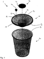
Figure 1 shows various parts of a device for growing a single crop unit according to the invention, including a mat for rooting the crop unit therein and a carrier for the mat formed as a lid, and a beaker on which said lid can be placed; -
Figure 2 shows the various parts ofFigure 1 in an assembled state; -
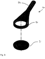
Figure 3 shows the mat ofFigure 1 in combination with a holder for the mat; -
Figures 4a and 4b respectively show a sowing or cutting tray and a carrier for the further cultivation of a plurality of crop units, each having a plurality of arrangement places on which each time an assembly of the parts ofFigure 3 is arranged; -
Figures 5a and 5b respectively show a carrier, with a plurality of set-up locations on which each time a lid as inFigure 1 is arranged, with in said lid an assembly of the parts ofFigure 3 and the parts ofFigure 1 in a assembled state, wherein the mat forms part of an assembly of the parts as shown inFigure 3 ; -
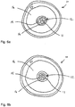
Figures 6a and 6b each show a plan view of a carrier formed as a lid as shown inFigure 1 ; -
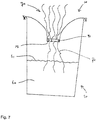
Figure 7 shows a mat-rooted crop supported in a carrier formed as a lid, the carrier being placed as a lid on a beaker with a volume of water; -
Figure 8 schematically shows a carrier according to the present invention. - With reference to
Figure 1 , adevice 1 for growing a crop unit comprises a medium 30 in which the plant unit can root, and acarrier 10 for the medium 30. - In the embodiment shown, the medium 30 comprises a
mat 31 of non-woven fiber material with capillary properties. Themat 31 in the shown embodiment is flat, round, and relatively thin. - The
carrier 10 has a recessedportion 12, in which themat 31 can be arranged, with a bottom 15 for supporting themat 31. In the bottom 15, openings are provided (not visible inFigure 1 ), which are covered by themat 31 when thatmat 31 is arranged in the recessedportion 12. - At a circumferential edge, the
carrier 10 is provided with anadditional opening 13, which is left uncovered by themat 31 when it is arranged in the recessedportion 12. - The
additional opening 13 can be closed with a separate cap 40. - Instead of a separate cap 40, another means can also be provided, which can be arranged to close off the
additional opening 13, which means may possibly be stuck to thecarrier 10, so that it can not be lost. For example, the means may comprise a tab that is to be bent to engage theadditional opening 13 to seal it. - The recessed
portion 12 has acircumferential wall 14, which, in the case of amat 31 placed at the bottom 15, extends over at least a certain height above themat 31. - Around the recessed
portion 12, adjacent to theperipheral wall 14, thecarrier 10 has aportion 16 which runs towards the recessedportion 12. Thecircumferential wall 14 and the descendingportion 16 thus form a funnel-shaped whole 14, 16 in the embodiment shown. - In the embodiment shown, the
mat 31 is separate from thesupport 10, although themat 31 can also be fixed to thesupport 10 within the invention, for example by being welded thereto. - The recessed
portion 12 has a round cross-section, so that themat 31, which in the embodiment shown is round as well, can be received in the recessedportion 12. - The
device 1 further comprises abeaker 20, while thecarrier 10 is formed as a lid which can be placed on that beaker. In the embodiment shown, thecarrier 10 has for this purpose asnap edge 17, which can be snapped onto a cooperating edge 21 of thecup 20. - With reference to
Figure 2 , in an assembled state of the parts ofFigure 1 , thecarrier 10 is placed on thebeaker 20 as a lid, wherein themat 31 is arranged in the recessedportion 12 of the lid-shapedcarrier 10, and wherein theadditional opening 13 is closed by the cap. - Certainly in the case that the
mat 31 is moist, thebeaker 20 in the state ofFIG. 2 is substantially air-tight and water-tight, by at least along theco-operating edges 17, 21 an air-tight and watertight closure of the lid-shapedcarrier 10 on thebeaker 20, an air-tight and watertight closure of the cap 40 on theadditional opening 13, and an obstruction to the passage of water and air through said openings in the bottom of the lid-like carrier 10, which is caused by sealing of that openings by themat 31. Theassembly 1 ofFig. 2 is therefore virtually leak-proof, even when it falls over or is kept upside down, and water from thecup 20 reaches thecarrier 10. - With reference to
Figure 3 , a holder 50 can be provided for securing themat 31 in or on acarrier 10. - In the embodiment shown, the holder 50 comprises an annular base portion 51, which is formed to secure itself against the
circumferential wall 14 of the recessedportion 12 of acarrier 10 as shown inFigure 1 . In the case of aloose mat 31, themat 31 is thus confined with respect to thecarrier 10, in order to be held against the bottom 15. However, themat 31 can also be fixed to the holder 50, and in particular to the ring-shaped base part 51, so that it is also secured by itself on thecarrier 10 by securing the holder 50, and together with the holder 50 manageable. For facilitating the securing and removal of the assembly of a holder 50 and themat 31, in the embodiment shown, anannular section 52 is provided with an projectingarm 52, which can serve as a handle - With reference to
Figure 4a , in an alternative embodiment, adevice 200 according to the invention comprises a carrier 210 with a plurality ofopenings 220, each of which is adapted to receive amat 31, or at least an assembly of amat 31 and a holder 50, to be able to serve as support for a plurality ofmats 31, for instance during germination of seed which can be provided on each of themats 31 in order to cultivate a crop unit on each of the set-up locations formed by theopenings 220. For that purpose, the carrier 210 can be placed in a humid environment. The carrier 210 shown serves in such a case as what is known under the term "seed or cutting tray". - With reference to
Figure 4b , adevice 100 according to the invention can also comprise a carrier, orculture element 110, withopenings 120 which form set-up locations for crop units to be cultivated, and which for this purpose each are arranged to receive amat 31 or an assembly of a holder 50 and amat 31, with a crop unit at a certain development stage on eachmat 31, saidopenings 120 being further apart than theopenings 220 of a seeding or cutting tray 210. When growing, crop units can at a certain moment be transplanted from a sowing or cutting tray to such a growing element by displacement of amat 31 with an optional holder 50 thereon. On harvest, the mat and any holder therefor can be cut loose from the crop units so that harvested crops can be further traded free of mat and carrier. - With reference to
Figure 5a , a device 100 'according to the invention may however, in a special embodiment, also comprise an element 110', which has a plurality of set-up locations 120', which are each arranged, or at least are adapted to the shape of acarrier 10 for amat 31 for raising an individual crop unit, with a possible holder 50 for thatmat 31, so as to be able to receive a plurality ofmats 31, each supported by aseparate carrier 10, and each of which via theircarrier 10 are supported by said element 110 '. This makes it possible, after the cultivation of a plurality of crop units, to handle each of these crop units separately with theircarrier 10. - With reference to
Figure 5b , eachcarrier 10 is advantageously formed as alid 10 for abeaker 20 as described above, so that after cultivation on a common supporting growing element 110', cultivated crop units can each be placed on theirown beaker 20, for further trading of the crop units while each crop unit remains "on water". - Crop units can, if desired, only be transplanted to
carriers 10 supported by a common element 110' after partial cultivation or sprouting on a seed or cutting tray, by transplantingmats 31 and any containers 50 therefor. - After growing on a sowing or cutting tray, crop units in a given development stage can also be placed directly in a
carrier 10 supported by abeaker 20, by transplantingmats 31 and any containers 50 therefor. -
Figures 6a and 6b illustrate the presence ofopenings 11 in the bottom 15 of the recessedportion 12 of acarrier 10 formed as a lid for a beaker. Theopenings 11 can be larger openings (Figure 6a ) or smaller ones, such as perforations of the bottom 15 (Figure 6b ). A single opening is also possible. The only criterion is that amat 31 or other medium 30 can cover an opening oropenings 11 in alid 10, or at least can seal a passage present through thelid 10, possibly by filling up such a passage. Such a function could in principle also be fulfilled by a thicker mat, or by, for example, a rolled-up mat. - With reference to
Figure 7 , in an assembly of acarrier 10 formed as a lid for on acup 20 and such abeaker 20, the bottom 15 of saidlid 10, or at least amat 31 supported by said bottom 15, or otherwise carried by thecarrier 10, is at some distance above thewater level 61 of a water volume 60 present in thebeaker 20. In the embodiment shown, themat 31 is in that case arranged in thelid 10 in such a way that it can be kept moist by condensation water which at the inner side of thelid 10 can run downwards, or at least along thelid 10, so as to reach theopenings 11 covered by the mat. A so-called "wicket", or moisture-conducting element that hangs in the water volume, and which extends up to or in themat 31, is absent. However, it is possible for the roots 71 of acrop 70 rooting in themat 31 to reach into the water volume in order to be able to provide thecrop 70 with water and nutrients. - In the foregoing it has been explained how, according to the invention, seedlings can root in an apparatus according to the present invention during the first stage of their life, even including germination. When the roots have grown sufficiently, they can be transferred to a plate-shaped carrier, which is provided with a plurality of through openings, and which floats in a water bath. Such a carrier consists in practice of a plate of polystyrene foam with light-conical holes, which are wider at the top than at the bottom. A holder with culture mat and rooted plant is placed in such a hole, and drops therein to a depth where the diameter of the conical hole is equal to the outside diameter of the holder. In the space below the holder, a substantially closed chamber is then defined, in which air is located and a humid atmosphere. This must be sufficient to allow the roots of the plant to grow further until they finally reach the water surface.
- The present invention also relates to an improvement of such a carrier.
- With existing carriers, it is a problem that they are made of Styrofoam (Tempex), or expanded polystyrene. Although this has a good buoyancy, it is a disadvantage that the material has intrinsic gaps and crevices in which organisms, such as algae and fungi, can settle. This problem worsens with time, as it is fragile and breaks quickly. It is possible to clean the surface of the carrier, but a cleaning operation never reaches the interior of such gaps and crevices, so that organisms remain that grow out within a short time again.
- Furthermore, it is a problem that the roots of the plant can grow in such gaps and crevices. The plants then get stuck to the carrier. When at some moment the plants have to be removed, the roots are torn broke, which not only slows down the removal process but, more importantly, causes damage to the root system, causing the plant to become more susceptible to germs.
- Furthermore, a problem is that the material absorbs water, and shrinks.
- Another problem with existing carriers is that the conical holes do not properly define the height where the holders come to rest. The distance from the plants to the water surface then varies from plant to plant, which translates to an uneven development of the different plants, which is undesirable for a grower.
- The present invention proposes an improved carrier where the problems mentioned are eliminated or at least reduced.
-
Figure 8 shows a schematic cross-section of a portion of a plate-shapedcarrier 800 according to the present invention. The plate-shaped carrier, which may for instance have a size of 1 x 1 m2 at a height of, for example, 5-10 cm, is formed as a hollow body, for example by blow molding, of a suitable plastic such as, for example, PVC, PE, PP. Such a material has a smooth outer surface, is robust, and can be cleaned thoroughly and easily. - The
carrier 800 has two mutually parallelmain surfaces carrier 800 hasvertical passages 810. Even if these passages are identical to the known passages, the material used already offers advantages over the presently usual Tempex. - In the embodiment shown, each
passage 810 has a firstconical portion 811 and a second conical portion 812. The firstconical portion 811 has its largest diameter at the firstmain surface 801, while the second conical portion 812 has its largest diameter at the secondmain surface 802 The respective cone-shapedside walls conical parts 811 and 812 meet at the narrowest part of thevertical passage 810; at this location, thevertical passage 810 is provided with an inwardly directedperipheral flange 813 formed integrally with theconical side walls - The
circumferential flange 813 provides a good definition of the height at which the holder with the plant comes to stand. - The
circumferential flange 813 can lie symmetrically between the two main surfaces. In the preferred embodiment shown, thiscircumferential flange 813, measured in a direction perpendicular to themain surfaces main surface 801 and a distance H2 the secondmain surface 802, with H2 smaller than H1. - Due to the asymmetrical shape, the
plate 800 can be used in two orientations. In the orientation shown, thecircumferential flange 813 is at a relatively short distance from the water surface. The small roots will quickly touch the water. Furthermore, as a result of adhesion to the surface of theside wall 822, the water will creep upwards and wet the material of themat 31, as a result of which a good airtight seal of the underlying space will be achieved. - When the roots have grown further, the plate can be reversed, which effectively results in the
circumferential flange 813 lying at relatively larger distance from the water surface. In addition, the space under themat 31 becomes larger, causing more air to be available. This is favorable for further development of the roots. - An advantage of the
carrier 800 proposed by the present invention is better thermal insulation. - In a further preferred embodiment, the
carrier 800 is substantially light-tight, in order to counteract algae growth in the space between thecircumferential flange 813 and the water surface. Algae growth is competitive with root growth, and in the event of death of the algae, the water becomes too rich in nitrates. - The light-tightness can be achieved by making the carrier of black plastic material, but this has the disadvantage that the carrier heats up relatively quickly. In order to avoid this temperature problem, the material is preferably of a very light color, preferably white. But light plastics have the disadvantage that the free path length of photons therein is longer, so that it is necessary to make the carrier of thicker material, but this has the disadvantage that the carrier becomes relatively heavy.
- In order to solve these problems together, the material of the
support 800 may have a two-layer or multilayer structure, wherein the outer layer is white, and wherein a deeper layer is black. This, however, requires the use of co-extrusion machines. In an alternative approach, the present invention proposes to use a white plastic, for example a PVC, PE, PP to which TiO2-based pigment has been added, and to add small light-blocking particles to the plastic material. When the dimensions of these particles are sufficiently small, these particles remain suspended in the liquid phase of the plastic. As the concentration of these particles increases, they will jointly block an ever increasing percentage of the transmitted light. Thanks to this aspect of the present invention, it is possible to achieve the same degree of light attenuation at a smaller material thickness, which saves material, saves material costs, and makes thecarriers 800 easier to handle. - It will be clear to a person skilled in the art that the invention is not limited to the exemplary embodiments discussed above, but that various variants and modifications are possible within the scope of the invention as defined in the appended claims. Even if certain features are mentioned in different dependent claims, the present invention also relates to an embodiment which has these features together. Even if certain features are described in combination with each other, the present invention also relates to an embodiment in which one or more of those features have been omitted. Features that are not explicitly described as being essential may also be omitted. Any reference numbers used in a claim should not be interpreted as limiting the scope of that claim.
Claims (18)
- A carrier (800) for receiving thin mats (31) having crop units rooted therein, said carrier being formed as a hollow body having two mutually parallel main surfaces (801, 802) which at a plurality of locations is provided with passages (810) extending between said main surfaces.
- Carrier according to claim 1, wherein each passage (810) comprises a first conical part (811) and a second conical part (812), which have their largest diameter at the respective main surfaces, and which meet each other at the narrowest part of the passage.
- Carrier according to claim 2, wherein the narrowest part of the passage is provided with an inwardly directed peripheral flange (813), which is preferably formed integrally with the conical side wall of the passage.
- Carrier according to claim 2 or 3, wherein the narrowest part of the passage is asymmetrical with respect to the main surfaces.
- Carrier according to any one of claims 1-4, wherein the carrier is substantially light-tight.
- Carrier according to claim 5, wherein the carrier is made of a plastic material to which light-blocking particles have been added.
- Device (1, 100, 100', 200) for cultivating at least one crop unit, comprising per plant unit a separate medium (30) for rooting the crop unit therein, and one or more carriers (10, 110, 110', 210) for the different media (30), wherein each medium (30) comprises a relatively thin mat (31) of a certain material, for example of capillary material, woven fiber material, non-woven fiber material.
- Device according to claim 7, wherein the carrier (10) is provided with one or more openings (11), the mat (31) being adapted to cover said one or more openings (11),
wherein the carrier (10) has a recessed portion (12), said one or more openings (11) being provided at the bottom of the recessed portion (12). - Device according to claim 8, wherein the carrier (10) is provided with an additional opening (13) that is left uncovered by the mat (31).
- Device according to claim 9, further comprising a sealing member (40) for sealing the additional opening (13).
- Device according to one of claims 8 to 10, wherein the recessed portion (12) has a circumferential wall (14) which extends over a certain height above the mat (31).
- Device according to one of claims 8 to 11, wherein the carrier (10) has, around the recessed portion (12), a portion (16) that runs towards the recessed portion (12).
- Device according to one of claims 7 to 12, wherein the carrier (10) comprises a lid (10) for a cup (20).
- Device according to one of claims 7 to 13, wherein the carrier {100, 100', 200) comprises an element (110, 110', 210) having a plurality of set-up locations (120, 120', 220) for receiving therein a medium (30) for rooting an individual crop unit therein, or
for receiving a carrier (10) as defined in one of those claims. - Device according to one of claims 7 to 14, further comprising a part (50) arranged to secure itself on the carrier (10, 110) for holding the mat (31) in place with respect to the carrier (10, 110, 210);- wherein said part (50) is optionally fixed to the mat (31) or at least holds the mat (31);and / or wherein said part (50) optionally comprises an annular part (51) and / or has an projecting arm or lip (52).
- Assembly of a device according to claim 13 and a cup (20), which can be closed by the carrier (10) as a lid,
the carrier (10) having, as lid (20), a snap edge (17) that can be snapped on an edge (21) of the cup (20), and
wherein the carrier (10) as a lid closes the cup (20) in airtight and watertight manner. - Assembly according to claim 16, wherein the lowest level of the carrier (10) as a lid, or at least the lowest level of a medium (30) supported by the carrier (10) as a lid for rooting a crop unit (50) therein, is above the maximum level of a water volume (60) present in the cup (20).
- A method for growing at least one crop unit, comprising the step of providing one or more carriers (10, 110, 210) for a medium (30) for allowing a crop unit to be rooted therein, and providing the one or more carriers (10, 110) with a relatively thin mat (31) of a specific material per crop unit;
optionally further comprising the step of placing in a sowing or cutting tray, or at least an element (210) with a number of relatively close receiving positions (220), a plurality of mats (31) in which crops units to be cultivated can root; moistening the element (210) concerned, or at least the mats (31) concerned; and transplanting said mats (31) with crop units to be cultivated thereon at a certain stage of development to a cultivation element, or at least an element (110) with a plurality of receiving positions (120) located further apart;
and / or optionally further comprising the step of placing mats (31) which each are provided on a container (50), and optionally transplanting these mats from a seed or cutting tray (210) to a carrier (10, 110);
and / or optionally further comprising the step of placing and optionally transplanting mats (31) from a seed or cutting tray (210), possibly on a container (50), to a carrier (10) formed as a lid for on a cup (20) or another reservoir for a volume of water;
and / or optionally further comprising the step of placing an assembly of a carrier (10) formed as a lid (10) with a mat (31) thereon, possibly on a container (50), on a cultivating element (110') having a plurality of reception positions (120') for receiving such carriers (10);
and / or optionally further comprising the step of transplanting a crop unit rooting in a mat (31) supported by a carrier formed as lid (10), from said lid (10) of a cultivation element (110') to a cup (20) or other reservoir for a volume of water.
Priority Applications (2)
| Application Number | Priority Date | Filing Date | Title |
|---|---|---|---|
| EP17001955.8A EP3491914B8 (en) | 2017-11-29 | 2017-11-29 | Carrier for receiving thin mats with crop units rooted therein, and device and method for cultivating one or more crop units |
| ES17001955T ES2978680T3 (en) | 2017-11-29 | 2017-11-29 | Carrier for receiving thin mats with culture units rooted thereon, and device and method for cultivating one or more culture units |
Applications Claiming Priority (1)
| Application Number | Priority Date | Filing Date | Title |
|---|---|---|---|
| EP17001955.8A EP3491914B8 (en) | 2017-11-29 | 2017-11-29 | Carrier for receiving thin mats with crop units rooted therein, and device and method for cultivating one or more crop units |
Publications (4)
| Publication Number | Publication Date |
|---|---|
| EP3491914A1 true EP3491914A1 (en) | 2019-06-05 |
| EP3491914B1 EP3491914B1 (en) | 2024-03-20 |
| EP3491914C0 EP3491914C0 (en) | 2024-03-20 |
| EP3491914B8 EP3491914B8 (en) | 2024-07-31 |
Family
ID=60856827
Family Applications (1)
| Application Number | Title | Priority Date | Filing Date |
|---|---|---|---|
| EP17001955.8A Active EP3491914B8 (en) | 2017-11-29 | 2017-11-29 | Carrier for receiving thin mats with crop units rooted therein, and device and method for cultivating one or more crop units |
Country Status (2)
| Country | Link |
|---|---|
| EP (1) | EP3491914B8 (en) |
| ES (1) | ES2978680T3 (en) |
Citations (6)
| Publication number | Priority date | Publication date | Assignee | Title |
|---|---|---|---|---|
| JPH0286716A (en) * | 1988-09-21 | 1990-03-27 | Kanai Hiroyuki | Device for water culture and method for water culture using the same |
| JPH0435753U (en) * | 1990-07-24 | 1992-03-25 | ||
| JPH0984465A (en) * | 1995-09-25 | 1997-03-31 | Fukusuke Kogyo Kk | Flowerpot |
| EP1457105A1 (en) * | 2003-02-27 | 2004-09-15 | Oekag Wassertechnik (Schweiz) AG | Plant carrier for sealed flat roofs |
| WO2012050449A1 (en) * | 2010-10-15 | 2012-04-19 | Holding B.V.Jalmaja | Cultivation assembly and method for growing crops |
| WO2017025711A2 (en) * | 2015-08-07 | 2017-02-16 | Biomatrix Water Solutions Limited | Floating ecosystem |
-
2017
- 2017-11-29 EP EP17001955.8A patent/EP3491914B8/en active Active
- 2017-11-29 ES ES17001955T patent/ES2978680T3/en active Active
Patent Citations (6)
| Publication number | Priority date | Publication date | Assignee | Title |
|---|---|---|---|---|
| JPH0286716A (en) * | 1988-09-21 | 1990-03-27 | Kanai Hiroyuki | Device for water culture and method for water culture using the same |
| JPH0435753U (en) * | 1990-07-24 | 1992-03-25 | ||
| JPH0984465A (en) * | 1995-09-25 | 1997-03-31 | Fukusuke Kogyo Kk | Flowerpot |
| EP1457105A1 (en) * | 2003-02-27 | 2004-09-15 | Oekag Wassertechnik (Schweiz) AG | Plant carrier for sealed flat roofs |
| WO2012050449A1 (en) * | 2010-10-15 | 2012-04-19 | Holding B.V.Jalmaja | Cultivation assembly and method for growing crops |
| WO2017025711A2 (en) * | 2015-08-07 | 2017-02-16 | Biomatrix Water Solutions Limited | Floating ecosystem |
Also Published As
| Publication number | Publication date |
|---|---|
| EP3491914B1 (en) | 2024-03-20 |
| ES2978680T3 (en) | 2024-09-17 |
| EP3491914B8 (en) | 2024-07-31 |
| EP3491914C0 (en) | 2024-03-20 |
Similar Documents
| Publication | Publication Date | Title |
|---|---|---|
| US5261185A (en) | Apparatus and method of water culture and plant handling method | |
| US4903432A (en) | Autoclavable, reusable, sterile plant growth system and method | |
| US20160270303A1 (en) | Floating plant propagation tray | |
| CN113329619B (en) | Floating boards and methods of growing plants thereon | |
| CA2752498C (en) | Method for cultivating plants as well as a floating carrier | |
| WO2012050449A1 (en) | Cultivation assembly and method for growing crops | |
| KR20190085453A (en) | Pot for ginseng | |
| JP3044352U (en) | Hydroponics | |
| CA3021598A1 (en) | Horticultural apparatus | |
| ES2978565T3 (en) | Articulated component, and mechanical system comprising said component | |
| JPH09135639A (en) | Plant cultivation method and apparatus thereof | |
| WO2023058257A1 (en) | Strawberry seedling growing system and growing method | |
| US11744196B2 (en) | Plant cultivating apparatus | |
| WO2018062987A1 (en) | Method and system for cultivating plant material | |
| JP7337405B2 (en) | Cultivation system for growing plants | |
| EP3491914B1 (en) | Carrier for receiving thin mats with crop units rooted therein, and device and method for cultivating one or more crop units | |
| JPH10271926A (en) | Planting plate for hydroponics | |
| JP6512453B2 (en) | Cultivation device, cultivation method | |
| JP4365976B2 (en) | Plant cultivation equipment | |
| JP2019187321A (en) | Cultivation pot | |
| JP2001204259A (en) | Bottom liquid absorption system and cultivation bed used for it | |
| CN110139554A (en) | Plant planting system with root barrier | |
| US10667476B2 (en) | Sustained release irrigation apparatus with pivoting cap | |
| JP3009115U (en) | Hydroponics equipment | |
| NL1041892B1 (en) | Device and method for cultivating one or more crop units |
Legal Events
| Date | Code | Title | Description |
|---|---|---|---|
| PUAI | Public reference made under article 153(3) epc to a published international application that has entered the european phase |
Free format text: ORIGINAL CODE: 0009012 |
|
| STAA | Information on the status of an ep patent application or granted ep patent |
Free format text: STATUS: THE APPLICATION HAS BEEN PUBLISHED |
|
| AK | Designated contracting states |
Kind code of ref document: A1 Designated state(s): AL AT BE BG CH CY CZ DE DK EE ES FI FR GB GR HR HU IE IS IT LI LT LU LV MC MK MT NL NO PL PT RO RS SE SI SK SM TR |
|
| AX | Request for extension of the european patent |
Extension state: BA ME |
|
| STAA | Information on the status of an ep patent application or granted ep patent |
Free format text: STATUS: REQUEST FOR EXAMINATION WAS MADE |
|
| RBV | Designated contracting states (corrected) |
Designated state(s): AL AT BE BG CH CY CZ DE DK EE ES FI FR GB GR HR HU IE IS IT LI LT LU LV MC MK MT NL NO PL PT RO RS SE SI SK SM TR |
|
| 17P | Request for examination filed |
Effective date: 20191205 |
|
| RBV | Designated contracting states (corrected) |
Designated state(s): AL AT BE BG CH CY CZ DE DK EE ES FI FR GB GR HR HU IE IS IT LI LT LU LV MC MK MT NL NO PL PT RO RS SE SI SK SM TR |
|
| STAA | Information on the status of an ep patent application or granted ep patent |
Free format text: STATUS: EXAMINATION IS IN PROGRESS |
|
| 17Q | First examination report despatched |
Effective date: 20230321 |
|
| GRAP | Despatch of communication of intention to grant a patent |
Free format text: ORIGINAL CODE: EPIDOSNIGR1 |
|
| STAA | Information on the status of an ep patent application or granted ep patent |
Free format text: STATUS: GRANT OF PATENT IS INTENDED |
|
| INTG | Intention to grant announced |
Effective date: 20231025 |
|
| GRAS | Grant fee paid |
Free format text: ORIGINAL CODE: EPIDOSNIGR3 |
|
| GRAA | (expected) grant |
Free format text: ORIGINAL CODE: 0009210 |
|
| STAA | Information on the status of an ep patent application or granted ep patent |
Free format text: STATUS: THE PATENT HAS BEEN GRANTED |
|
| AK | Designated contracting states |
Kind code of ref document: B1 Designated state(s): AL AT BE BG CH CY CZ DE DK EE ES FI FR GB GR HR HU IE IS IT LI LT LU LV MC MK MT NL NO PL PT RO RS SE SI SK SM TR |
|
| REG | Reference to a national code |
Ref country code: GB Ref legal event code: FG4D |
|
| REG | Reference to a national code |
Ref country code: CH Ref legal event code: EP |
|
| REG | Reference to a national code |
Ref country code: DE Ref legal event code: R096 Ref document number: 602017080143 Country of ref document: DE |
|
| REG | Reference to a national code |
Ref country code: IE Ref legal event code: FG4D |
|
| U01 | Request for unitary effect filed |
Effective date: 20240416 |
|
| GRAT | Correction requested after decision to grant or after decision to maintain patent in amended form |
Free format text: ORIGINAL CODE: EPIDOSNCDEC |
|
| PG25 | Lapsed in a contracting state [announced via postgrant information from national office to epo] |
Ref country code: GR Free format text: LAPSE BECAUSE OF FAILURE TO SUBMIT A TRANSLATION OF THE DESCRIPTION OR TO PAY THE FEE WITHIN THE PRESCRIBED TIME-LIMIT Effective date: 20240621 |
|
| REG | Reference to a national code |
Ref country code: CH Ref legal event code: PK Free format text: BERICHTIGUNG B8 |
|
| RAP4 | Party data changed (patent owner data changed or rights of a patent transferred) |
Owner name: METEOR SYSTEMS B.V. Owner name: DIRVEN, SEBASTIAAN JOHANNES HENDRICUS |
|
| U07 | Unitary effect registered |
Designated state(s): AT BE BG DE DK EE FI FR IT LT LU LV MT NL PT SE SI Effective date: 20240618 |
|
| PG25 | Lapsed in a contracting state [announced via postgrant information from national office to epo] |
Ref country code: HR Free format text: LAPSE BECAUSE OF FAILURE TO SUBMIT A TRANSLATION OF THE DESCRIPTION OR TO PAY THE FEE WITHIN THE PRESCRIBED TIME-LIMIT Effective date: 20240320 Ref country code: RS Free format text: LAPSE BECAUSE OF FAILURE TO SUBMIT A TRANSLATION OF THE DESCRIPTION OR TO PAY THE FEE WITHIN THE PRESCRIBED TIME-LIMIT Effective date: 20240620 |
|
| PG25 | Lapsed in a contracting state [announced via postgrant information from national office to epo] |
Ref country code: RS Free format text: LAPSE BECAUSE OF FAILURE TO SUBMIT A TRANSLATION OF THE DESCRIPTION OR TO PAY THE FEE WITHIN THE PRESCRIBED TIME-LIMIT Effective date: 20240620 Ref country code: HR Free format text: LAPSE BECAUSE OF FAILURE TO SUBMIT A TRANSLATION OF THE DESCRIPTION OR TO PAY THE FEE WITHIN THE PRESCRIBED TIME-LIMIT Effective date: 20240320 Ref country code: GR Free format text: LAPSE BECAUSE OF FAILURE TO SUBMIT A TRANSLATION OF THE DESCRIPTION OR TO PAY THE FEE WITHIN THE PRESCRIBED TIME-LIMIT Effective date: 20240621 |
|
| REG | Reference to a national code |
Ref country code: ES Ref legal event code: FG2A Ref document number: 2978680 Country of ref document: ES Kind code of ref document: T3 Effective date: 20240917 |
|
| PG25 | Lapsed in a contracting state [announced via postgrant information from national office to epo] |
Ref country code: IS Free format text: LAPSE BECAUSE OF FAILURE TO SUBMIT A TRANSLATION OF THE DESCRIPTION OR TO PAY THE FEE WITHIN THE PRESCRIBED TIME-LIMIT Effective date: 20240720 |
|
| PG25 | Lapsed in a contracting state [announced via postgrant information from national office to epo] |
Ref country code: SM Free format text: LAPSE BECAUSE OF FAILURE TO SUBMIT A TRANSLATION OF THE DESCRIPTION OR TO PAY THE FEE WITHIN THE PRESCRIBED TIME-LIMIT Effective date: 20240320 |
|
| PG25 | Lapsed in a contracting state [announced via postgrant information from national office to epo] |
Ref country code: CZ Free format text: LAPSE BECAUSE OF FAILURE TO SUBMIT A TRANSLATION OF THE DESCRIPTION OR TO PAY THE FEE WITHIN THE PRESCRIBED TIME-LIMIT Effective date: 20240320 |
|
| PG25 | Lapsed in a contracting state [announced via postgrant information from national office to epo] |
Ref country code: PL Free format text: LAPSE BECAUSE OF FAILURE TO SUBMIT A TRANSLATION OF THE DESCRIPTION OR TO PAY THE FEE WITHIN THE PRESCRIBED TIME-LIMIT Effective date: 20240320 |
|
| PG25 | Lapsed in a contracting state [announced via postgrant information from national office to epo] |
Ref country code: SK Free format text: LAPSE BECAUSE OF FAILURE TO SUBMIT A TRANSLATION OF THE DESCRIPTION OR TO PAY THE FEE WITHIN THE PRESCRIBED TIME-LIMIT Effective date: 20240320 |
|
| PG25 | Lapsed in a contracting state [announced via postgrant information from national office to epo] |
Ref country code: SM Free format text: LAPSE BECAUSE OF FAILURE TO SUBMIT A TRANSLATION OF THE DESCRIPTION OR TO PAY THE FEE WITHIN THE PRESCRIBED TIME-LIMIT Effective date: 20240320 Ref country code: SK Free format text: LAPSE BECAUSE OF FAILURE TO SUBMIT A TRANSLATION OF THE DESCRIPTION OR TO PAY THE FEE WITHIN THE PRESCRIBED TIME-LIMIT Effective date: 20240320 Ref country code: RO Free format text: LAPSE BECAUSE OF FAILURE TO SUBMIT A TRANSLATION OF THE DESCRIPTION OR TO PAY THE FEE WITHIN THE PRESCRIBED TIME-LIMIT Effective date: 20240320 Ref country code: PL Free format text: LAPSE BECAUSE OF FAILURE TO SUBMIT A TRANSLATION OF THE DESCRIPTION OR TO PAY THE FEE WITHIN THE PRESCRIBED TIME-LIMIT Effective date: 20240320 Ref country code: IS Free format text: LAPSE BECAUSE OF FAILURE TO SUBMIT A TRANSLATION OF THE DESCRIPTION OR TO PAY THE FEE WITHIN THE PRESCRIBED TIME-LIMIT Effective date: 20240720 Ref country code: CZ Free format text: LAPSE BECAUSE OF FAILURE TO SUBMIT A TRANSLATION OF THE DESCRIPTION OR TO PAY THE FEE WITHIN THE PRESCRIBED TIME-LIMIT Effective date: 20240320 |
|
| U20 | Renewal fee for the european patent with unitary effect paid |
Year of fee payment: 8 Effective date: 20241028 |
|
| REG | Reference to a national code |
Ref country code: DE Ref legal event code: R097 Ref document number: 602017080143 Country of ref document: DE |
|
| PLBE | No opposition filed within time limit |
Free format text: ORIGINAL CODE: 0009261 |
|
| STAA | Information on the status of an ep patent application or granted ep patent |
Free format text: STATUS: NO OPPOSITION FILED WITHIN TIME LIMIT |
|
| 26N | No opposition filed |
Effective date: 20241223 |
|
| U1N | Appointed representative for the unitary patent procedure changed after the registration of the unitary effect |
Representative=s name: PATENTWERK B.V.; NL |
|
| REG | Reference to a national code |
Ref country code: CH Ref legal event code: PL |
|
| PG25 | Lapsed in a contracting state [announced via postgrant information from national office to epo] |
Ref country code: MC Free format text: LAPSE BECAUSE OF FAILURE TO SUBMIT A TRANSLATION OF THE DESCRIPTION OR TO PAY THE FEE WITHIN THE PRESCRIBED TIME-LIMIT Effective date: 20240320 |
|
| REG | Reference to a national code |
Ref country code: CH Ref legal event code: PL |
|
| PG25 | Lapsed in a contracting state [announced via postgrant information from national office to epo] |
Ref country code: CH Free format text: LAPSE BECAUSE OF NON-PAYMENT OF DUE FEES Effective date: 20241130 |
|
| PG25 | Lapsed in a contracting state [announced via postgrant information from national office to epo] |
Ref country code: IE Free format text: LAPSE BECAUSE OF NON-PAYMENT OF DUE FEES Effective date: 20241129 |
|
| U20 | Renewal fee for the european patent with unitary effect paid |
Year of fee payment: 9 Effective date: 20251126 |
|
| PGFP | Annual fee paid to national office [announced via postgrant information from national office to epo] |
Ref country code: GB Payment date: 20251127 Year of fee payment: 9 |
|
| PGFP | Annual fee paid to national office [announced via postgrant information from national office to epo] |
Ref country code: NO Payment date: 20251128 Year of fee payment: 9 |
|
| PGFP | Annual fee paid to national office [announced via postgrant information from national office to epo] |
Ref country code: ES Payment date: 20251201 Year of fee payment: 9 |
|
| PG25 | Lapsed in a contracting state [announced via postgrant information from national office to epo] |
Ref country code: HU Free format text: LAPSE BECAUSE OF FAILURE TO SUBMIT A TRANSLATION OF THE DESCRIPTION OR TO PAY THE FEE WITHIN THE PRESCRIBED TIME-LIMIT; INVALID AB INITIO Effective date: 20171129 |
|
| PG25 | Lapsed in a contracting state [announced via postgrant information from national office to epo] |
Ref country code: CY Free format text: LAPSE BECAUSE OF FAILURE TO SUBMIT A TRANSLATION OF THE DESCRIPTION OR TO PAY THE FEE WITHIN THE PRESCRIBED TIME-LIMIT; INVALID AB INITIO Effective date: 20171129 |
|
| PG25 | Lapsed in a contracting state [announced via postgrant information from national office to epo] |
Ref country code: TR Free format text: LAPSE BECAUSE OF FAILURE TO SUBMIT A TRANSLATION OF THE DESCRIPTION OR TO PAY THE FEE WITHIN THE PRESCRIBED TIME-LIMIT Effective date: 20240320 |