EP3491632B1 - Apparatus to simulate driving and corresponding method - Google Patents
Apparatus to simulate driving and corresponding method Download PDFInfo
- Publication number
- EP3491632B1 EP3491632B1 EP17742458.7A EP17742458A EP3491632B1 EP 3491632 B1 EP3491632 B1 EP 3491632B1 EP 17742458 A EP17742458 A EP 17742458A EP 3491632 B1 EP3491632 B1 EP 3491632B1
- Authority
- EP
- European Patent Office
- Prior art keywords
- driver
- inflatable pads
- control
- driving
- unit
- Prior art date
- Legal status (The legal status is an assumption and is not a legal conclusion. Google has not performed a legal analysis and makes no representation as to the accuracy of the status listed.)
- Active
Links
Images




Classifications
-
- G—PHYSICS
- G09—EDUCATION; CRYPTOGRAPHY; DISPLAY; ADVERTISING; SEALS
- G09B—EDUCATIONAL OR DEMONSTRATION APPLIANCES; APPLIANCES FOR TEACHING, OR COMMUNICATING WITH, THE BLIND, DEAF OR MUTE; MODELS; PLANETARIA; GLOBES; MAPS; DIAGRAMS
- G09B9/00—Simulators for teaching or training purposes
- G09B9/02—Simulators for teaching or training purposes for teaching control of vehicles or other craft
- G09B9/04—Simulators for teaching or training purposes for teaching control of vehicles or other craft for teaching control of land vehicles
- G09B9/042—Simulators for teaching or training purposes for teaching control of vehicles or other craft for teaching control of land vehicles providing simulation in a real vehicle
-
- G—PHYSICS
- G09—EDUCATION; CRYPTOGRAPHY; DISPLAY; ADVERTISING; SEALS
- G09B—EDUCATIONAL OR DEMONSTRATION APPLIANCES; APPLIANCES FOR TEACHING, OR COMMUNICATING WITH, THE BLIND, DEAF OR MUTE; MODELS; PLANETARIA; GLOBES; MAPS; DIAGRAMS
- G09B9/00—Simulators for teaching or training purposes
- G09B9/02—Simulators for teaching or training purposes for teaching control of vehicles or other craft
- G09B9/04—Simulators for teaching or training purposes for teaching control of vehicles or other craft for teaching control of land vehicles
-
- A—HUMAN NECESSITIES
- A47—FURNITURE; DOMESTIC ARTICLES OR APPLIANCES; COFFEE MILLS; SPICE MILLS; SUCTION CLEANERS IN GENERAL
- A47C—CHAIRS; SOFAS; BEDS
- A47C7/00—Parts, details, or accessories of chairs or stools
- A47C7/36—Supports for the head or the back
- A47C7/40—Supports for the head or the back for the back
- A47C7/46—Supports for the head or the back for the back with special, e.g. adjustable, lumbar region support profile; "Ackerblom" profile chairs
- A47C7/467—Supports for the head or the back for the back with special, e.g. adjustable, lumbar region support profile; "Ackerblom" profile chairs adjustable by fluid means
-
- G—PHYSICS
- G09—EDUCATION; CRYPTOGRAPHY; DISPLAY; ADVERTISING; SEALS
- G09B—EDUCATIONAL OR DEMONSTRATION APPLIANCES; APPLIANCES FOR TEACHING, OR COMMUNICATING WITH, THE BLIND, DEAF OR MUTE; MODELS; PLANETARIA; GLOBES; MAPS; DIAGRAMS
- G09B9/00—Simulators for teaching or training purposes
- G09B9/02—Simulators for teaching or training purposes for teaching control of vehicles or other craft
-
- G—PHYSICS
- G09—EDUCATION; CRYPTOGRAPHY; DISPLAY; ADVERTISING; SEALS
- G09B—EDUCATIONAL OR DEMONSTRATION APPLIANCES; APPLIANCES FOR TEACHING, OR COMMUNICATING WITH, THE BLIND, DEAF OR MUTE; MODELS; PLANETARIA; GLOBES; MAPS; DIAGRAMS
- G09B9/00—Simulators for teaching or training purposes
- G09B9/02—Simulators for teaching or training purposes for teaching control of vehicles or other craft
- G09B9/08—Simulators for teaching or training purposes for teaching control of vehicles or other craft for teaching control of aircraft, e.g. Link trainer
-
- G—PHYSICS
- G09—EDUCATION; CRYPTOGRAPHY; DISPLAY; ADVERTISING; SEALS
- G09B—EDUCATIONAL OR DEMONSTRATION APPLIANCES; APPLIANCES FOR TEACHING, OR COMMUNICATING WITH, THE BLIND, DEAF OR MUTE; MODELS; PLANETARIA; GLOBES; MAPS; DIAGRAMS
- G09B9/00—Simulators for teaching or training purposes
- G09B9/02—Simulators for teaching or training purposes for teaching control of vehicles or other craft
- G09B9/08—Simulators for teaching or training purposes for teaching control of vehicles or other craft for teaching control of aircraft, e.g. Link trainer
- G09B9/10—Simulators for teaching or training purposes for teaching control of vehicles or other craft for teaching control of aircraft, e.g. Link trainer with simulated flight- or engine-generated force being applied to aircraft occupant
-
- G—PHYSICS
- G09—EDUCATION; CRYPTOGRAPHY; DISPLAY; ADVERTISING; SEALS
- G09B—EDUCATIONAL OR DEMONSTRATION APPLIANCES; APPLIANCES FOR TEACHING, OR COMMUNICATING WITH, THE BLIND, DEAF OR MUTE; MODELS; PLANETARIA; GLOBES; MAPS; DIAGRAMS
- G09B9/00—Simulators for teaching or training purposes
- G09B9/02—Simulators for teaching or training purposes for teaching control of vehicles or other craft
- G09B9/08—Simulators for teaching or training purposes for teaching control of vehicles or other craft for teaching control of aircraft, e.g. Link trainer
- G09B9/12—Motion systems for aircraft simulators
-
- G—PHYSICS
- G09—EDUCATION; CRYPTOGRAPHY; DISPLAY; ADVERTISING; SEALS
- G09B—EDUCATIONAL OR DEMONSTRATION APPLIANCES; APPLIANCES FOR TEACHING, OR COMMUNICATING WITH, THE BLIND, DEAF OR MUTE; MODELS; PLANETARIA; GLOBES; MAPS; DIAGRAMS
- G09B9/00—Simulators for teaching or training purposes
- G09B9/02—Simulators for teaching or training purposes for teaching control of vehicles or other craft
- G09B9/08—Simulators for teaching or training purposes for teaching control of vehicles or other craft for teaching control of aircraft, e.g. Link trainer
- G09B9/12—Motion systems for aircraft simulators
- G09B9/14—Motion systems for aircraft simulators controlled by fluid actuated piston or cylinder ram
Definitions
- the present invention concerns an apparatus to simulate driving a land vehicle such as an automobile, a sports car, a bus, a truck, or suchlike.
- the simulation apparatus comprises at least one seat in which a driver takes his place and is subjected to different stresses suitable to reproduce actual driving conditions.
- Land vehicle driving simulators are known, an example of which is described in WO-A-2013/114179 , which comprises at least one platform mobile with respect to a support plane and with which at least one seat for a driver is associated.
- the mobile platform and the support plane movement devices are interposed, provided to move at least the mobile platform and to reproduce the stresses that occur during driving, such as lateral displacement, acceleration/deceleration and swerving.
- the seat is associated with the mobile platform by means of additional hexapod-shaped movement devices that allow to simulate, in combination with the movement devices associated with the support plane and the mobile platform, the stresses to which a driver is normally subjected, such as rolling, swerving, pitching, acceleration/deceleration.
- Aeronautical simulators are also known, an example of which is described in document US-A-3,309,795 , which comprise a seat installed in a fixed position with respect to a plane that supports the simulator and to which inflatable pads are associated.
- the inflatable pads are usually associated with the seating plane and the backrest, and are selectively inflated/deflated to induce further stresses on the driver in order to increase his sensation of driving a vehicle.
- simulators used in the aeronautical field cannot be effectively adopted in the automobile sector or, more generally, on land vehicles.
- a simulator is also known, from document GB-A-2.328.192 , provided with a base plate, a platform and a plurality of actuators provided to move the platform with respect to the base plate. This document does not describe the positioning of seats on the mobile platform at all.
- One purpose of the present invention is to obtain an apparatus suitable to make the simulation of driving a land vehicle performed by a simulator more realistic, thus increasing the exposure time of a driver to accelerations and thus providing a much more realistic simulation of the inertial environment to which the driver is subjected during driving.
- Another purpose of the present invention is to obtain a driving simulation apparatus that produces stimuli, or "cues", which are extremely faithful to what usually happens when driving a land vehicle.
- Another purpose of the present invention is to provide a driving simulation apparatus able to stimulate the vestibular system and the driver's contact to increase his sense of really driving a vehicle.
- Another purpose is to perfect a method for simulating driving a land vehicle that is extremely effective and realistic.
- the Applicant has devised, tested and embodied the present invention to overcome the shortcomings of the state of the art and to obtain these and other purposes and advantages.
- an apparatus to simulate driving land vehicles comprises:
- inflatable pads are associated with at least some of the contact surfaces of the seat and are fluidically connected to a pumping unit that is configured to control the pressure of a gas inside the inflatable pads and to induce tactile pressure stresses on the driver.
- the apparatus comprises a control and command unit connected to the movement devices, to the driving control unit and to at least the pumping unit and configured to selectively control the driving control unit and the pumping unit in order to combine the dynamic stresses of the movement devices and the tactile pressure stresses of the inflatable pads on the driver.
- the actuation of the pumping unit is determined in relation to the actuation of the movement devices.
- the control and command unit comprises and implements a coupling algorithm able to manage, in real time, at least the movement accelerations of the mobile platform and the tactile pressure stresses of the inflatable pads, by coordinating the actuation of said movement devices and said pumping unit.
- the coupling algorithm can implement a dynamic model of the seated human body, used to connect contact forces and pressures acting on the driver, to then couple the latter with the vestibular model and the movement of the platform.
- the configuration of the simulation apparatus described above is particularly suitable to simulate the dynamics of a land vehicle in which, for example, the stresses of acceleration or deceleration to which a driver is subjected can be greatly extended over time with respect to what occurs in aeronautical simulations.
- This combination of actions allows to manage stimuli on the driver affecting different sensory areas, that is, it is able to obtain the integration between a first subsystem, deriving from vestibular perceptions that are activated by dynamic stresses, or inertia, induced by the movement of the mobile platform, and a second subsystem deriving from somatosensory perceptions of the driver that are activated by the pressures generated by the inflatable pads.
- These pressures of the inflatable pads are interpreted by the driver's brain as additional information about the state of the vehicle. The more realistic the reproduction of the pressure, the simpler the driver's ability to use this information will be, reducing the perceived conflict between the real and the virtual, and potentially reducing the occurrence of malaise of the driver during the simulation.
- the apparatus comprises seatbelts associated with the seat and configured to secure the driver.
- the seatbelts are connected to a tightening device configured to selectively vary the tightening of the seatbelts on the driver.
- the tightening device in its turn is connected to the control and command unit, which as a function of the driving simulation required manages the tightening mode of the seatbelts.
- the control of the traction on the seatbelts coordinated with a control of the gas pressure in the inflatable pads and a control of the drive of the movement devices allows the driver to perceive the sensation of braking and/or deceleration sensation of the land vehicle. For example, it can be provided that while the driver brakes, he perceives the seatbelts more adhering to his torso, while his back perceives the backrest of the seat distant from it.
- the present invention also concerns a method to simulate driving land vehicles that provides to install a seat on a mobile platform, to position a driver resting on contact surfaces of the seat, to detect the actions of the driver on driving command members, to process the actions of the driver on the driving command members with a driving control unit, and to determine the actuation of movement devices to move the mobile platform with respect to a support plane as a function of the actions on the driving command members and to induce dynamic stresses on the driver.
- the method provides to control, using a pumping unit, the pressure of a gas inside inflatable pads associated with at least some of the contact surfaces in order to induce tactile pressure stresses on the driver.
- a control and command unit is connected to the movement devices, to the driving control unit and to at least the pumping unit and selectively controls the driving control unit and the pumping unit and combines with respect to each other the dynamic stresses of the movement devices and the tactile pressure stresses of the inflatable pads on the driver.
- the actuation of the pumping unit is determined in relation to the actuation of the movement devices.
- the method provides to secure the driver to the seat with seatbelts and to selectively vary the tightening of the seatbelts on the driver by controlling the tightening action with the control and command unit.
- the simulation apparatus 10 comprises a seat 11 provided with contact surfaces 14 on which a driver C is positioned during use.
- the simulation apparatus 10 comprises driving command members 27, 28, 29, 34 drivable by the driver C to simulate driving action, for example acceleration, deceleration, braking, turning, gear change or suchlike.
- the driving command members can be selected from a group comprising at least one of either a steering wheel 27, a brake pedal 28, a clutch pedal 29, an accelerator pedal 34 on which the driver C can act with his or her feet or hands, to simulate pre-defined driving conditions.
- sensors configured to detect movements such as for example rotation, pressure, movement or suchlike, induced on the driving command members 27, 28, 29, 34, are associated with each of said driving command members 27, 28, 29, 34 themselves.
- the data detected by the sensors is subsequently processed to extrapolate subsequent actions to be induced on the driver C as described hereafter.
- the seat 11 is installed on a mobile platform 30 which in turn is connected to movement devices 31 configured to move the mobile platform 30 with respect to, for example, a support plane 35.
- the movement devices 31 can comprise, by way of example only, at least one of either linear actuators, guides, wheels, aerodynamic bearings, or suchlike.
- the movement devices 31 can comprise a hexapod structure configured to move the mobile platform 30 according to at least six degrees of freedom.
- the movement of the mobile platform 30 allows to induce dynamic stresses on the driver such as inertia or centrifugal forces.
- the mobile platform 30 can simulate the body of a vehicle, for example an automobile.
- a projection screen can also be associated with the mobile platform 30 for projecting images of the environment in which the driver C is immersed while driving.
- the simulation apparatus 10 comprises a driving control unit 32 connected to the movement devices 31 and the driving command members 27, 28, 29, 34 to control and command the drive modes of the movement devices 31 in relation to the action of the driver C on the driving command members 27, 28, 29, 34.
- the driving control unit 32 allows to translate these actions into the movement of the movement devices 31.
- the seat 11 may be provided with a seating plane 12 and at least one backrest 13.
- the seating plane 12 and the backrest 13 can be provided with padding elements to make the seat comfortable and ergonomic for the driver C.
- the seating plane 12 and the backrest 13 are provided with respective contact surfaces 14 on which the driver C is positioned during use.
- the contact surfaces 14 of the seating plane 12 are disposed transversely with respect to the contact surfaces 14 of the backrest 13, to define a concave conformation of the seat 11 to accommodate the driver C.
- inflatable pads are associated with at least some of the contact surfaces 14 of the seat 11, in the case shown here first inflatable pads 15 and second inflatable pads 18, selectively inflatable/deflatable to induce on the driver C tactile pressure stresses functional to simulate driving a land vehicle.
- the first inflatable pads 15, which are selectively inflatable with a gas, are associated with the seating plane 12 and the backrest 13, to modify the sensation of pressure that the driver C perceives from the seat 11 following actions of driving simulations.
- the first inflatable pads 15 can be integrated into the thickness of the seating plane 12 and/or the backrest 13.
- the first inflatable pads 15 may be associated externally to the seating plane 12 and/or the backrest 13 on the opposite side with respect to the contact surfaces 14, and the inflation/deflation of the first inflatable pads 15 determines an elastic deformation of the seating plane 12 and/or the backrest 13 which leads to a variation in the sensation of pressure of the seat 11 on the driver C.
- the first inflatable pads 15 can themselves define the seating plane 12 and the backrest 13, or at least part of these. In still other variant embodiments, the first inflatable pads 15 are positioned above the contact surfaces 14 of the seating plane 12 and of the backrest 13.
- the backrest 13 and/or the seating plane 12 are each provided with at least two first inflatable pads 15 reciprocally distanced from each other on the respective contact surfaces 14 to differentiate on the driver C the tactile pressure stresses, for example to simulate an imbalance to the right or left of driver C himself.
- the seating plane 12 and the backrest 13 are provided with respective lateral edges 16 opposite each other and substantially defining the width of the seating plane 12 and the backrest 13.
- the seating plane 12 and the backrest 13, in correspondence with their respective lateral edges 16, are provided with lateral containing portions 17 protruding transversely with respect to the respective contact surfaces 14.
- the containing portions 17 thus define a lateral containment for the driver C and, in turn, respective contact surfaces 14 with the latter.
- the containing portions 17 can comprise and/or be defined by padding elements and/or containing shells.
- the containing portions 17 of the seating plane 12 and the backrest 13 can be made in a single body as shown in figs. 1-3 or, alternatively, they can be made as distinct and separate elements.
- the second inflatable pads 18 are associated with the containing portions 17, and are selectively inflatable with a gas to modify the sensation of pressure that the containing portions 17 exert on the driver C.
- second inflatable pads 18 on the containing portions 17 allows to increase the efficiency of the stimulation on the driver C to obtain driving simulations that are extremely faithful to the reality of a land vehicle.
- the second inflatable pads 18 allow to complete the simulation at least of the swerve of a land vehicle.
- the combination of actions on the first inflatable pads 15 and on the second inflatable pads 18 allows to simulate the roll, swerve, pitch, acceleration/deceleration that a land vehicle is normally subjected to.
- the second inflatable pads 18 can be integrated in, or positioned above, the lateral containing portions 17 of the seating plane 12 and the backrest 13.
- the second inflatable pads 18 can themselves define the containing portions 17 of the seating plane 12 and the backrest 13.
- One, two or more inflatable pads 18 can be associated with each containing portion 17 of the seating plane 12 and/or the backrest 13.
- the simulation apparatus 10 comprises a pumping unit 19 configured to control the pressure of a gas inside the first inflatable pads 15 and the second inflatable pads 18 and therefore to induce tactile pressure stresses on the driver C.
- the pumping unit 19 is fluidically connected to the first inflatable pads 15 and to the second inflatable pads 18 and is configured to control the pressure of the gas inside them.
- the pumping unit 19 in fact, allows to selectively introduce and/or release the gas contained in the first inflatable pads 15 and the second inflatable pads 18, so as to adjust the pressure in the latter.
- air is introduced into the first inflatable pads 15 and the second inflatable pads 18.
- the pumping unit 19 comprises a pumping device 21 to pump the gas, or air, fluidically connected to a distributor device 22.
- the pumping device 21 can comprise a compressor, for example rotary or alternative type.
- the distributor device 22 is connected, with respective pipes 23, to the first inflatable pads 15 and to the second inflatable pads 18.
- the simulation apparatus 10 also comprises a control and command unit 20 connected at least to the movement devices 31, the pumping unit 19 and the driving control unit 32 and configured to control both the pumping unit 19 and also the driving control unit 32, and to combine the dynamic stresses induced by the movement devices 31 and the tactile pressure stresses induced by the inflatable pads 15 and 18 on the driver C.
- the actuation of the pumping unit 19 is also determined in relation to the actuation of the movement devices 31.
- control and command unit 20 is configured to estimate the action modes on the movement devices 31 and the inflatable pads 15, 18.
- the control and command unit 20 can comprise and implement at least one coupling algorithm to coordinate the actuation of the movement devices 31 and of the pumping unit 19.
- the coupling algorithm combines the tactile perceptive dynamics of a person with a series of mass spring damper models suitable to emulate the reaction of the human body when subjected to accelerations and rotations.
- the results obtained by this coupling algorithm subsequently determine the tactile pressure actions to be imparted to the seat 11 by means of the inflatable pads 15, 18, and the entities of movement, that is, speeds and accelerations to be imparted to the mobile platform 30 by means of the movement devices 31.
- the coupling algorithm has been developed by taking into consideration, by way of example only, the inertial reaction of the driver C, the frictions that are generated between the body of the driver C and the seat 11, the material of the seat 11, the nonlinear rigidity and the damping effect of the body of the driver C.
- control and command unit 20 can receive information regarding actions on the driving command members 27, 28, 29, 34 and, as a function of this information, manages both the actuation of the driving control unit 32 and therefore conditions the functioning of the movement devices 31 and the actuation of the inflatable pads 15, 18 and therefore conditions the functioning of the pumping unit 19.
- the control and command unit 20 can receive information regarding actions on the driving command members 27, 28, 29, 34 and, as a function of this information, manages both the actuation of the driving control unit 32 and therefore conditions the functioning of the movement devices 31 and the actuation of the inflatable pads 15, 18 and therefore conditions the functioning of the pumping unit 19.
- control and command unit 20 can be configured to independently control and command the pressure of the gases in the first inflatable pads 15 and in the second inflatable pads 18.
- control and command unit 20 it is possible to send commands to the pumping unit 19 so that it suitably adjusts the pressure in the first inflatable pads 15 and in the second inflatable pads 18.
- control and command unit 20 is connected to the distributor device 22 to selectively control the supply of gas in the first inflatable pads 15 and the second inflatable pads 18 and to adjust the pressure thereof independently.
- each inflatable pad whether it is comprised among the first inflatable pads 15 or among the second inflatable pads 18, can be independently connected to the distributor device 22 which is configured to manage the level of inflation of each of them.
- This solution allows to precisely control the level of inflation of each pad, and in this way it can also manage precisely the required simulation modes.
- the distributor device 22 comprises distributor valves 24 fluidically connected to the first inflatable pads 15 and to the second inflatable pads 18 and selectively drivable by the control and command unit 20.
- the distributor valves 24 can comprise servo-commanded valves, for example electro valves, pneumatic drive valves, or suchlike.
- the distributor valves 24 can be connected to the first inflatable pads 15 and to the second inflatable pads 18 by means of the pipes 23.
- Each pad whether it is one of the first inflatable pads 15 or the second inflatable pads 18, can be connected to a respective distributor valve 24, and each of the latter is selectively commanded by the control and command unit 20 according to the specific simulations required.
- the distributor device 22 comprises discharge valves 25 fluidically connected to the first inflatable pads 15 and to the second inflatable pads 18 and selectively drivable by the control and command unit 20 to control the discharge of gas from the first inflatable pads 15 and second inflatable pads 18.
- the discharge valves 25 can comprise servo-commanded valves.
- control and command unit 20 suitably coordinating the management of the distributor valves 24 and the discharge valves 25, allows to independently manage the gas pressure in the first inflatable pads 15 and in the second inflatable pads 18 by introducing or respectively discharging the gas.
- the apparatus comprises seatbelts 26 associated with the seat 11 and configured to secure the driver C.
- the seatbelts 26 are connected to a tightening device 33 configured to selectively vary the tension of the seatbelts 26 on the driver C.
- the tightening device 33 is, in turn, connected to the control and command unit 20 which, in relation to the simulation conditions, releases or tightens the seatbelts 26, for example to simulate a forward or backward movement of the driver C.
- simulation apparatus 10 provided only the action of the movement devices 31, for them to have a high exposure time of the driver C, they would require big movement travels of the mobile platform 30, with all the problems connected therewith.
- the present invention also concerns a method for simulating driving using the apparatus 10.
- the method is based on actions commanded by the driver C based on the driving travel that is being performed, and in general corresponding to an acceleration, deceleration caused by gear change, right or left turn, braking, or combinations thereof.
- the driver C imparts actions by means of the driving command members 27, 28, 29, 34, and these actions are converted into signals sent to the driving control unit 32 and to the control and command unit 20.
- the data provided to manage the functioning of the pumping unit 19 can be converted at least into values of flow rate and air pressure to be sent to the first inflatable pads 15 and to the second inflatable pads 18.
- the control and command unit 20 manages the drive of the distributor device 22, for example of the distributor valves 24 and the discharge valves 25, to adjust the air pressure to be maintained and/or generated in the first inflatable pads 15 and in the second inflatable pads 18, as a function of the intensity of the acceleration, deceleration, steering, braking, or combinations thereof.
- the data detected by the action on the driving command members 27, 28, 29, 34 can be processed by the control and command unit 20 to generate particular tension conditions to be transferred to the tightening device 33 of the seatbelts 26.
- the first inflatable pads 15 positioned in correspondence with the backrest 13 are inflated according to the intensity of the acceleration, while the remaining first inflatable pads 15 of the seating plane 12 and the second inflatable pads 18 are deflated.
- the first inflatable pads 15 positioned in correspondence with the backrest 13 are deflated when a negative longitudinal acceleration is developed, for example when the clutch pedal 29 is pressed, and are then deflated again when the longitudinal acceleration returns positive, after the change of gear.
- the remaining first inflatable pads 15 and the second inflatable pads 18 are deflated.
- the second inflatable pads 18 positioned in correspondence with the containing portion 17 respectively left ( fig. 6 ) or right ( fig. 7 ) are inflated according to the lateral acceleration developed, while the first inflatable pads 15 and the remaining second inflatable pads 18 are deflated.
- the first inflatable pads 15 positioned in correspondence with the seating plane 12 are inflated or deflated.
- the seatbelts 26 are in the inactive position.
- the first inflatable pads 15 and the second inflatable pads 18 are deflated, while the seatbelts 26 are in a traction position, that is, they are perceived by the driver C as being very adherent to him.
Landscapes
- Engineering & Computer Science (AREA)
- Theoretical Computer Science (AREA)
- Aviation & Aerospace Engineering (AREA)
- Business, Economics & Management (AREA)
- Physics & Mathematics (AREA)
- Educational Administration (AREA)
- Educational Technology (AREA)
- General Physics & Mathematics (AREA)
- Seats For Vehicles (AREA)
- Control Of Electric Motors In General (AREA)
- Special Chairs (AREA)
Description
- The present invention concerns an apparatus to simulate driving a land vehicle such as an automobile, a sports car, a bus, a truck, or suchlike.
- In particular, the simulation apparatus according to the invention comprises at least one seat in which a driver takes his place and is subjected to different stresses suitable to reproduce actual driving conditions.
- Land vehicle driving simulators are known, an example of which is described in
WO-A-2013/114179 , which comprises at least one platform mobile with respect to a support plane and with which at least one seat for a driver is associated. - Between the mobile platform and the support plane movement devices are interposed, provided to move at least the mobile platform and to reproduce the stresses that occur during driving, such as lateral displacement, acceleration/deceleration and swerving.
- In accordance with the solution described in
WO-A-2013/114179 , the seat is associated with the mobile platform by means of additional hexapod-shaped movement devices that allow to simulate, in combination with the movement devices associated with the support plane and the mobile platform, the stresses to which a driver is normally subjected, such as rolling, swerving, pitching, acceleration/deceleration. - Due to physical-mechanical limitations, these types of dynamic driving simulators are typically used to reproduce transient phenomena.
- One rather strong disadvantage of this type of simulator is that it is impossible to provide the driver with so-called "sustained accelerations", that is, accelerations that extend over time. The absence of sustained accelerations is one of the main factors that contribute to increasing the conflict between the real and the virtual environment that typically produces malaise in untrained drivers.
- Aeronautical simulators are also known, an example of which is described in document
US-A-3,309,795 , which comprise a seat installed in a fixed position with respect to a plane that supports the simulator and to which inflatable pads are associated. - The inflatable pads are usually associated with the seating plane and the backrest, and are selectively inflated/deflated to induce further stresses on the driver in order to increase his sensation of driving a vehicle.
- Indeed it is known that in the aeronautical field the main stresses to which a pilot is subjected are acceleration/deceleration in the three coordinated directions, and rolling.
- It is also known that the entity of such stresses are completely different in the aeronautical sector compared with those in the field of land vehicles, if for no other reason than the different dynamics to which a land vehicle is subjected compared to an aeronautical vehicle. Such types of aeronautical simulators, compared to land vehicle simulators, are conceived as static simulators, that is, the seating plane is normally fixed with respect to a support platform. This makes aeronautical simulators unsuitable for an application to land vehicle simulators.
- For these reasons, simulators used in the aeronautical field cannot be effectively adopted in the automobile sector or, more generally, on land vehicles.
- A simulator is also known, from document
GB-A-2.328.192 - One purpose of the present invention is to obtain an apparatus suitable to make the simulation of driving a land vehicle performed by a simulator more realistic, thus increasing the exposure time of a driver to accelerations and thus providing a much more realistic simulation of the inertial environment to which the driver is subjected during driving.
- Another purpose of the present invention is to obtain a driving simulation apparatus that produces stimuli, or "cues", which are extremely faithful to what usually happens when driving a land vehicle.
- Another purpose of the present invention is to provide a driving simulation apparatus able to stimulate the vestibular system and the driver's contact to increase his sense of really driving a vehicle.
- Another purpose is to perfect a method for simulating driving a land vehicle that is extremely effective and realistic.
- The Applicant has devised, tested and embodied the present invention to overcome the shortcomings of the state of the art and to obtain these and other purposes and advantages.
- The present invention is set forth and characterized in the independent claims 1 and 8, while the dependent claims describe other characteristics of the invention or variants to the main inventive idea.
- In accordance with the above purposes, an apparatus to simulate driving land vehicles comprises:
- a mobile platform,
- a seat installed on the mobile platform and provided with contact surfaces on which, during use, a driver is positioned,
- driving command members which can be actuated by the driver to simulate a driving action, such as acceleration, braking, turning, gear change or other,
- movement devices configured to move the mobile platform with respect to a support plane and to induce dynamic stresses on the driver which involve for example his/her somatosensory apparatuses and in particular his/her vestibular apparatus,
- a driving control unit connected to the driving command members and to said movement devices and configured to command the drive of the movement devices as a function of the actions of the driver on the driving command members.
- According to one aspect of the present invention, inflatable pads are associated with at least some of the contact surfaces of the seat and are fluidically connected to a pumping unit that is configured to control the pressure of a gas inside the inflatable pads and to induce tactile pressure stresses on the driver.
- Moreover, the apparatus according to the present invention comprises a control and command unit connected to the movement devices, to the driving control unit and to at least the pumping unit and configured to selectively control the driving control unit and the pumping unit in order to combine the dynamic stresses of the movement devices and the tactile pressure stresses of the inflatable pads on the driver. The actuation of the pumping unit is determined in relation to the actuation of the movement devices.
- The control and command unit comprises and implements a coupling algorithm able to manage, in real time, at least the movement accelerations of the mobile platform and the tactile pressure stresses of the inflatable pads, by coordinating the actuation of said movement devices and said pumping unit. To this purpose, the coupling algorithm can implement a dynamic model of the seated human body, used to connect contact forces and pressures acting on the driver, to then couple the latter with the vestibular model and the movement of the platform.
- The configuration of the simulation apparatus described above is particularly suitable to simulate the dynamics of a land vehicle in which, for example, the stresses of acceleration or deceleration to which a driver is subjected can be greatly extended over time with respect to what occurs in aeronautical simulations.
- Indeed, by the combination and synergy of the control and drive of the pumping unit and the driving control unit, it is possible to combine together the stresses that the movement devices and the inflatable pads can induce on the driver so as optimize and increase the accuracy of reproducing a drive simulation.
- This combination of actions allows to manage stimuli on the driver affecting different sensory areas, that is, it is able to obtain the integration between a first subsystem, deriving from vestibular perceptions that are activated by dynamic stresses, or inertia, induced by the movement of the mobile platform, and a second subsystem deriving from somatosensory perceptions of the driver that are activated by the pressures generated by the inflatable pads. These pressures of the inflatable pads, in fact, are interpreted by the driver's brain as additional information about the state of the vehicle. The more realistic the reproduction of the pressure, the simpler the driver's ability to use this information will be, reducing the perceived conflict between the real and the virtual, and potentially reducing the occurrence of malaise of the driver during the simulation.
- According to possible embodiments of the invention, the apparatus comprises seatbelts associated with the seat and configured to secure the driver. The seatbelts are connected to a tightening device configured to selectively vary the tightening of the seatbelts on the driver. The tightening device in its turn is connected to the control and command unit, which as a function of the driving simulation required manages the tightening mode of the seatbelts.
- The control of the traction on the seatbelts, coordinated with a control of the gas pressure in the inflatable pads and a control of the drive of the movement devices allows the driver to perceive the sensation of braking and/or deceleration sensation of the land vehicle. For example, it can be provided that while the driver brakes, he perceives the seatbelts more adhering to his torso, while his back perceives the backrest of the seat distant from it.
- The advantages of the present invention are many:
- the movement of the mobile platform, the actuation of the inflatable pads and the possible seatbelts are perfectly coordinated by means of a coupling model or algorithm implemented in the control and command unit;
- the coupling algorithm is optimized to obtain a tactile stimulus that is as near to the real as possible, improving overall realism;
- malaise can also be reduced for non-experienced drivers by increasing the class of potential simulator users;
- the presence of a single coupling algorithm makes the adjustment method simple: no further adjustment is required of the actuation modes of the inflatable pads and possible seatbelts every time the motion cueing model is modified.
- The present invention also concerns a method to simulate driving land vehicles that provides to install a seat on a mobile platform, to position a driver resting on contact surfaces of the seat, to detect the actions of the driver on driving command members, to process the actions of the driver on the driving command members with a driving control unit, and to determine the actuation of movement devices to move the mobile platform with respect to a support plane as a function of the actions on the driving command members and to induce dynamic stresses on the driver.
- According to one aspect, the method provides to control, using a pumping unit, the pressure of a gas inside inflatable pads associated with at least some of the contact surfaces in order to induce tactile pressure stresses on the driver. Furthermore, a control and command unit is connected to the movement devices, to the driving control unit and to at least the pumping unit and selectively controls the driving control unit and the pumping unit and combines with respect to each other the dynamic stresses of the movement devices and the tactile pressure stresses of the inflatable pads on the driver. The actuation of the pumping unit is determined in relation to the actuation of the movement devices.
- According to possible embodiments of the invention, the method provides to secure the driver to the seat with seatbelts and to selectively vary the tightening of the seatbelts on the driver by controlling the tightening action with the control and command unit.
- These and other characteristics of the present invention will become apparent from the following description of some embodiments, given as a non-restrictive example with reference to the attached drawings wherein:
-
fig. 1 is a lateral section view of a driving simulation apparatus in accordance with a possible embodiment of the present invention; -
fig. 2 is a perspective exploded front view of a driving simulation apparatus in accordance with a possible embodiment; -
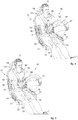
fig. 3 is a rear perspective view of the apparatus offig. 2 in an assembled condition; -
figs. 4-8 are perspective views of the apparatus offig. 2 in different configurations. - To facilitate comprehension, the same reference numbers have been used, where possible, to identify identical common elements in the drawings. It is understood that elements and characteristics of one embodiment can conveniently be incorporated into other embodiments without further clarifications.
- With reference to
figs. 1 to 3 , we will now describe possible embodiments of the present invention relating to asimulation apparatus 10 for driving land vehicles. - The
simulation apparatus 10 comprises aseat 11 provided with contact surfaces 14 on which a driver C is positioned during use. - According to a possible solution of the present invention, the
simulation apparatus 10 comprises drivingcommand members 27, 28, 29, 34 drivable by the driver C to simulate driving action, for example acceleration, deceleration, braking, turning, gear change or suchlike. - The driving command members can be selected from a group comprising at least one of either a
steering wheel 27, a brake pedal 28, a clutch pedal 29, an accelerator pedal 34 on which the driver C can act with his or her feet or hands, to simulate pre-defined driving conditions. - In particular, it can be provided that sensors configured to detect movements such as for example rotation, pressure, movement or suchlike, induced on the driving
command members 27, 28, 29, 34, are associated with each of said drivingcommand members 27, 28, 29, 34 themselves. The data detected by the sensors is subsequently processed to extrapolate subsequent actions to be induced on the driver C as described hereafter. - According to another aspect of the invention, the
seat 11 is installed on amobile platform 30 which in turn is connected tomovement devices 31 configured to move themobile platform 30 with respect to, for example, asupport plane 35. - The
movement devices 31 can comprise, by way of example only, at least one of either linear actuators, guides, wheels, aerodynamic bearings, or suchlike. - According to possible solutions, the
movement devices 31 can comprise a hexapod structure configured to move themobile platform 30 according to at least six degrees of freedom. - The movement of the
mobile platform 30 allows to induce dynamic stresses on the driver such as inertia or centrifugal forces. - The
mobile platform 30 can simulate the body of a vehicle, for example an automobile. - A projection screen can also be associated with the
mobile platform 30 for projecting images of the environment in which the driver C is immersed while driving. - According to a possible solution, the
simulation apparatus 10 comprises a drivingcontrol unit 32 connected to themovement devices 31 and the drivingcommand members 27, 28, 29, 34 to control and command the drive modes of themovement devices 31 in relation to the action of the driver C on the drivingcommand members 27, 28, 29, 34. - In particular, by detecting the actions of the driver C on the driving
command members 27 28, 29, 34 for example by means of said sensors, the drivingcontrol unit 32 allows to translate these actions into the movement of themovement devices 31. - The
seat 11 may be provided with aseating plane 12 and at least onebackrest 13. - The
seating plane 12 and thebackrest 13 can be provided with padding elements to make the seat comfortable and ergonomic for the driver C. - The
seating plane 12 and thebackrest 13 are provided with respective contact surfaces 14 on which the driver C is positioned during use. - The contact surfaces 14 of the
seating plane 12 are disposed transversely with respect to the contact surfaces 14 of thebackrest 13, to define a concave conformation of theseat 11 to accommodate the driver C. - According to one aspect of the present invention, inflatable pads are associated with at least some of the contact surfaces 14 of the
seat 11, in the case shown here firstinflatable pads 15 and secondinflatable pads 18, selectively inflatable/deflatable to induce on the driver C tactile pressure stresses functional to simulate driving a land vehicle. - According to a possible embodiment, the first
inflatable pads 15, which are selectively inflatable with a gas, are associated with theseating plane 12 and thebackrest 13, to modify the sensation of pressure that the driver C perceives from theseat 11 following actions of driving simulations. - According to possible embodiments, the first
inflatable pads 15 can be integrated into the thickness of theseating plane 12 and/or thebackrest 13. - According to possible variant embodiments, the first
inflatable pads 15 may be associated externally to theseating plane 12 and/or thebackrest 13 on the opposite side with respect to the contact surfaces 14, and the inflation/deflation of the firstinflatable pads 15 determines an elastic deformation of theseating plane 12 and/or thebackrest 13 which leads to a variation in the sensation of pressure of theseat 11 on the driver C. - According to other embodiments, the first
inflatable pads 15 can themselves define theseating plane 12 and thebackrest 13, or at least part of these. In still other variant embodiments, the firstinflatable pads 15 are positioned above the contact surfaces 14 of theseating plane 12 and of thebackrest 13. - According to possible solutions of the present invention, the
backrest 13 and/or theseating plane 12 are each provided with at least two firstinflatable pads 15 reciprocally distanced from each other on the respective contact surfaces 14 to differentiate on the driver C the tactile pressure stresses, for example to simulate an imbalance to the right or left of driver C himself. - According to possible embodiments, the
seating plane 12 and thebackrest 13 are provided with respectivelateral edges 16 opposite each other and substantially defining the width of theseating plane 12 and thebackrest 13. - The
seating plane 12 and thebackrest 13, in correspondence with their respective lateral edges 16, are provided with lateral containingportions 17 protruding transversely with respect to the respective contact surfaces 14. - The containing
portions 17 thus define a lateral containment for the driver C and, in turn, respective contact surfaces 14 with the latter. - The containing
portions 17 can comprise and/or be defined by padding elements and/or containing shells. - The containing
portions 17 of theseating plane 12 and thebackrest 13 can be made in a single body as shown infigs. 1-3 or, alternatively, they can be made as distinct and separate elements. - According to one aspect of the present invention, the second
inflatable pads 18 are associated with the containingportions 17, and are selectively inflatable with a gas to modify the sensation of pressure that the containingportions 17 exert on the driver C. - The presence of second
inflatable pads 18 on the containingportions 17 allows to increase the efficiency of the stimulation on the driver C to obtain driving simulations that are extremely faithful to the reality of a land vehicle. By way of example only, it can be provided that the secondinflatable pads 18 allow to complete the simulation at least of the swerve of a land vehicle. - The combination of actions on the first
inflatable pads 15 and on the secondinflatable pads 18 allows to simulate the roll, swerve, pitch, acceleration/deceleration that a land vehicle is normally subjected to. - The second
inflatable pads 18 can be integrated in, or positioned above, thelateral containing portions 17 of theseating plane 12 and thebackrest 13. - According to possible variant embodiments, the second
inflatable pads 18 can themselves define the containingportions 17 of theseating plane 12 and thebackrest 13. - One, two or more
inflatable pads 18 can be associated with each containingportion 17 of theseating plane 12 and/or thebackrest 13. - According to another aspect of the present invention, the
simulation apparatus 10 comprises apumping unit 19 configured to control the pressure of a gas inside the firstinflatable pads 15 and the secondinflatable pads 18 and therefore to induce tactile pressure stresses on the driver C. - According to some embodiments of the invention, the
pumping unit 19 is fluidically connected to the firstinflatable pads 15 and to the secondinflatable pads 18 and is configured to control the pressure of the gas inside them. - The
pumping unit 19, in fact, allows to selectively introduce and/or release the gas contained in the firstinflatable pads 15 and the secondinflatable pads 18, so as to adjust the pressure in the latter. - According to an advantageous solution, air is introduced into the first
inflatable pads 15 and the secondinflatable pads 18. - According to a possible embodiment, the
pumping unit 19 comprises apumping device 21 to pump the gas, or air, fluidically connected to adistributor device 22. - The
pumping device 21 can comprise a compressor, for example rotary or alternative type. - The
distributor device 22 is connected, withrespective pipes 23, to the firstinflatable pads 15 and to the secondinflatable pads 18. - The
simulation apparatus 10 also comprises a control andcommand unit 20 connected at least to themovement devices 31, thepumping unit 19 and the drivingcontrol unit 32 and configured to control both thepumping unit 19 and also the drivingcontrol unit 32, and to combine the dynamic stresses induced by themovement devices 31 and the tactile pressure stresses induced by theinflatable pads pumping unit 19 is also determined in relation to the actuation of themovement devices 31. - Advantageously, the control and
command unit 20 is configured to estimate the action modes on themovement devices 31 and theinflatable pads - The control and
command unit 20 can comprise and implement at least one coupling algorithm to coordinate the actuation of themovement devices 31 and of thepumping unit 19. - The coupling algorithm combines the tactile perceptive dynamics of a person with a series of mass spring damper models suitable to emulate the reaction of the human body when subjected to accelerations and rotations. The results obtained by this coupling algorithm subsequently determine the tactile pressure actions to be imparted to the
seat 11 by means of theinflatable pads mobile platform 30 by means of themovement devices 31. - The coupling algorithm has been developed by taking into consideration, by way of example only, the inertial reaction of the driver C, the frictions that are generated between the body of the driver C and the
seat 11, the material of theseat 11, the nonlinear rigidity and the damping effect of the body of the driver C. - Furthermore, the control and
command unit 20 can receive information regarding actions on the drivingcommand members 27, 28, 29, 34 and, as a function of this information, manages both the actuation of the drivingcontrol unit 32 and therefore conditions the functioning of themovement devices 31 and the actuation of theinflatable pads pumping unit 19. For example, it is possible to provide a continuous exchange of the data detected and processed by the drivingcontrol unit 32 through the sensors associated with the drivingcommand members 27, 28, 29, 34, to supply them to the control andcommand unit 20. Indeed, between the actions induced by themovement devices 31 and the inflation and deflation of the firstinflatable pads 15 and the secondinflatable pads 18 there is a complete synergy in order to optimize the driving simulation and make it effective. - In other embodiments, the control and
command unit 20 can be configured to independently control and command the pressure of the gases in the firstinflatable pads 15 and in the secondinflatable pads 18. - In particular, by means of the control and
command unit 20, it is possible to send commands to thepumping unit 19 so that it suitably adjusts the pressure in the firstinflatable pads 15 and in the secondinflatable pads 18. - According to a possible solution, the control and
command unit 20 is connected to thedistributor device 22 to selectively control the supply of gas in the firstinflatable pads 15 and the secondinflatable pads 18 and to adjust the pressure thereof independently. - According to possible solutions, each inflatable pad, whether it is comprised among the first
inflatable pads 15 or among the secondinflatable pads 18, can be independently connected to thedistributor device 22 which is configured to manage the level of inflation of each of them. This solution allows to precisely control the level of inflation of each pad, and in this way it can also manage precisely the required simulation modes. - According to a possible variant embodiment, the
distributor device 22 comprisesdistributor valves 24 fluidically connected to the firstinflatable pads 15 and to the secondinflatable pads 18 and selectively drivable by the control andcommand unit 20. - The
distributor valves 24 can comprise servo-commanded valves, for example electro valves, pneumatic drive valves, or suchlike. - The
distributor valves 24 can be connected to the firstinflatable pads 15 and to the secondinflatable pads 18 by means of thepipes 23. - Each pad, whether it is one of the first
inflatable pads 15 or the secondinflatable pads 18, can be connected to arespective distributor valve 24, and each of the latter is selectively commanded by the control andcommand unit 20 according to the specific simulations required. - According to possible embodiments, the
distributor device 22 comprisesdischarge valves 25 fluidically connected to the firstinflatable pads 15 and to the secondinflatable pads 18 and selectively drivable by the control andcommand unit 20 to control the discharge of gas from the firstinflatable pads 15 and secondinflatable pads 18. - According to possible embodiments, the
discharge valves 25 can comprise servo-commanded valves. - In particular, the control and
command unit 20, suitably coordinating the management of thedistributor valves 24 and thedischarge valves 25, allows to independently manage the gas pressure in the firstinflatable pads 15 and in the secondinflatable pads 18 by introducing or respectively discharging the gas. - According to a possible solution, the apparatus comprises
seatbelts 26 associated with theseat 11 and configured to secure the driver C. - The
seatbelts 26 are connected to atightening device 33 configured to selectively vary the tension of theseatbelts 26 on the driver C. - The tightening
device 33 is, in turn, connected to the control andcommand unit 20 which, in relation to the simulation conditions, releases or tightens theseatbelts 26, for example to simulate a forward or backward movement of the driver C. - During the simulation it is therefore possible to induce on the driver C three different stresses, that is, the dynamic stresses due to the movement devices, the pressure stresses due to the
inflatable pads seatbelts 26. By suitably coordinating these stresses it is possible to optimize the drive of themovement devices 31 and increase the exposure time of the driver C to the simulation stresses. - If the
simulation apparatus 10 provided only the action of themovement devices 31, for them to have a high exposure time of the driver C, they would require big movement travels of themobile platform 30, with all the problems connected therewith. - With the present invention, therefore, it is possible to obtain extremely
compact simulation apparatuses 10, which at the same time are able to expose the driver C to simulation stresses extending over time. - The present invention also concerns a method for simulating driving using the
apparatus 10. - Generally, the method is based on actions commanded by the driver C based on the driving travel that is being performed, and in general corresponding to an acceleration, deceleration caused by gear change, right or left turn, braking, or combinations thereof.
- The driver C imparts actions by means of the driving
command members 27, 28, 29, 34, and these actions are converted into signals sent to the drivingcontrol unit 32 and to the control andcommand unit 20. - These data are processed to manage the functioning at least of the
movement devices 31 and thepumping unit 19. - In particular, the data provided to manage the functioning of the
pumping unit 19 can be converted at least into values of flow rate and air pressure to be sent to the firstinflatable pads 15 and to the secondinflatable pads 18. - The control and
command unit 20 manages the drive of thedistributor device 22, for example of thedistributor valves 24 and thedischarge valves 25, to adjust the air pressure to be maintained and/or generated in the firstinflatable pads 15 and in the secondinflatable pads 18, as a function of the intensity of the acceleration, deceleration, steering, braking, or combinations thereof. - Furthermore, the data detected by the action on the driving
command members 27, 28, 29, 34 can be processed by the control andcommand unit 20 to generate particular tension conditions to be transferred to the tighteningdevice 33 of theseatbelts 26. - In the case of simulation of acceleration of a land vehicle (
fig. 4 ), the firstinflatable pads 15 positioned in correspondence with thebackrest 13 are inflated according to the intensity of the acceleration, while the remaining firstinflatable pads 15 of theseating plane 12 and the secondinflatable pads 18 are deflated. - In this way the driver C perceives his back pressed against the
backrest 13. - In the case of simulation of a deceleration (
fig. 5 ), in particular during the incremental shift of the driving gear, the firstinflatable pads 15 positioned in correspondence with thebackrest 13 are deflated when a negative longitudinal acceleration is developed, for example when the clutch pedal 29 is pressed, and are then deflated again when the longitudinal acceleration returns positive, after the change of gear. The remaining firstinflatable pads 15 and the secondinflatable pads 18 are deflated. - In this way, the perception of the driver C of being in contact with the
backrest 13 decreases. - In the case of simulation of a right turn (
fig. 6 ) or a left turn (fig. 7 ), the secondinflatable pads 18 positioned in correspondence with the containingportion 17 respectively left (fig. 6 ) or right (fig. 7 ) are inflated according to the lateral acceleration developed, while the firstinflatable pads 15 and the remaining secondinflatable pads 18 are deflated. - In the case of simulation of possible discontinuities in the ground, the first
inflatable pads 15 positioned in correspondence with theseating plane 12 are inflated or deflated. - In these four cases, the
seatbelts 26 are in the inactive position. - In the case of simulation of braking (
fig. 8 ), the firstinflatable pads 15 and the secondinflatable pads 18 are deflated, while theseatbelts 26 are in a traction position, that is, they are perceived by the driver C as being very adherent to him. - It is clear that modifications and/or additions of parts may be made to the
apparatus 10 and method for simulating driving land vehicles as described heretofore, without departing from the field and scope of the present invention. - It is also clear that, although the present invention has been described with reference to some specific examples, a person of skill in the art shall certainly be able to achieve many other equivalent forms of
apparatus 10 and method for simulating driving land vehicles, having the characteristics as set forth in the claims and hence all coming within the field of protection defined thereby.
Claims (9)
- Apparatus to simulate driving land vehicles comprising a mobile platform (30); a seat (11) installed on said mobile platform (30) and provided with contact surfaces (14) on which, during use, a driver (C) is positioned; driving command members (27, 28, 29, 34) which can be actuated by said driver (C) to simulate a driving action; movement devices (31) configured to move said mobile platform (30) with respect to a support plane (35) and to induce dynamic stresses on said driver (C); and a driving control unit (32) connected to said driving command members (27, 28, 29, 34) and to said movement devices (31) and configured to command the drive of said movement members (31) as a function of the actions of the driver (C) on said driving command members (27, 28, 29, 34), characterized in that inflatable pads (15, 18) are associated with at least some of said contact surfaces (14) and are fluidically connected to a pumping unit (19) configured to control the pressure of a gas inside said inflatable pads (15, 18) and to induce tactile pressure stresses on said driver (C), and in that said seat (11) comprises a seating plane (12) and a backrest (13) provided with said contact surfaces (14) and with which first inflatable pads (15) are associated, fluidically connected to said pumping unit (19), wherein in correspondence with their respective lateral edges (16), said seating plane (12) and said backrest (13) are provided with lateral containing portions (17) protruding transversely with respect to said contact surfaces (14), second inflatable pads (18) being associated with said containing portions (17), and connected to said pumping unit (19) to control the pressure of the gas inside said second inflatable pads (18), and in that it comprises a control and command unit (20) connected to said movement devices (31), to said driving control unit (32) and to at least said pumping unit (19) and configured to selectively control said driving control unit (32) and said pumping unit (19) and to combine the dynamic stresses of said movement devices (31) and the tactile pressure stresses of said inflatable pads (15, 18) on said driver (C), the actuation of said pumping unit (19) being determined in relation to the actuation of said movement devices (31).
- Apparatus as in claim 1, characterized in that said control and command unit (20) comprises and implements a coupling algorithm able to manage, in real time, at least the movement accelerations of said mobile platform (30) and the tactile pressure stresses of said inflatable pads (15, 18), by coordinating the actuation of said movement devices (31) and said pumping unit (19).
- Apparatus as in claim 1 or 2, characterized in that it comprises seatbelts (26) associated with said seat (11) and configured to secure said driver (C), and in that said seatbelts (26) are connected to a tightening device (33) configured to selectively vary the tightening of said seatbelts (26) on said driver (C), said tightening device (33) being connected to said control and command unit (20).
- Apparatus as in claim 1, characterized in that said control and command unit (20) is configured to selectively and independently control the pressure of said first inflatable pads (15) and of said second inflatable pads (18).
- Apparatus as in any claim hereinbefore, characterized in that said pumping unit (19) comprises a pumping device (21) of said gas, fluidically connected to a distributor device (22), said distributor device (22) being connected, with respective pipes (23), to said first inflatable pads (15) and to said second inflatable pads (18), and in that said control and command unit (20) is connected to said distributor device (22) to selectively control the feed of said gas to said first inflatable pads (15) and said second inflatable pads (18).
- Apparatus as in claim 5, characterized in that said distributor device (22) comprises distributor valves (24) and discharge valves (25) fluidically connected to said first inflatable pads (15) and said second inflatable pads (18) and selectively drivable by said control and command unit (20) to respectively control the introduction and discharge of said gas to/from said first inflatable pads (15) and said second inflatable pads (18).
- Apparatus as in any claim hereinbefore, characterized in that said driving command members are chosen from a group comprising at least one of either a steering wheel (27), a brake pedal (28), a clutch (29) or an accelerator pedal (34).
- Method to simulate driving land vehicles that provides to install a seat (11) on a mobile platform (30), to position a driver (C) on contact surfaces (14) of said seat (11), to detect the actions of said driver (C) on driving command members (27, 28, 29, 34), to process the actions of said driver (C) on said driving command members (27, 28, 29, 34) with a driving control unit (32), and to determine the actuation of movement devices (31) to move said mobile platform (30) with respect to a support plane (35) as a function of the actions of said driver (C) on said driving command members (27, 28, 29, 34) and to induce dynamic stresses on said driver (C), characterized in that, using a pumping unit (19), it provides to control the pressure of a gas inside inflatable pads (15,18) associated with at least some of said contact surfaces (14) in order to induce tactile pressure stresses on said driver (C), first inflatable pads (15) being associated with said contact surfaces (14) and second inflatable pads (18) being associated with containing portions (17) protruding transversely with respect to said contact surfaces (14), in that a control and command unit (20) is connected to said movement devices (31), to said driving control unit (32) and to at least said pumping unit (19) and selectively controls said driving control unit (32) and said pumping unit (19) and combines with respect to each other the dynamic stresses of said movement devices (31) and the tactile pressure stresses of said inflatable pads (15, 18) on said driver (C), and in that the actuation of said pumping unit (19) is determined in relation to the actuation of said movement devices (31).
- Method as in claim 8, characterized in that it provides to secure said driver (C) to said seat (11) with seatbelts (26) and to selectively vary the tightening of said seatbelts (26) on said driver (C) by controlling the tightening action with said control and command unit (20).
Applications Claiming Priority (2)
| Application Number | Priority Date | Filing Date | Title |
|---|---|---|---|
| IT102016000079351A IT201600079351A1 (en) | 2016-07-28 | 2016-07-28 | SYSTEM FOR DRIVING SIMULATION AND ITS PROCEDURE |
| PCT/EP2017/069084 WO2018019964A1 (en) | 2016-07-28 | 2017-07-27 | Apparatus to simulate driving and corresponding method |
Publications (2)
| Publication Number | Publication Date |
|---|---|
| EP3491632A1 EP3491632A1 (en) | 2019-06-05 |
| EP3491632B1 true EP3491632B1 (en) | 2021-02-17 |
Family
ID=57610205
Family Applications (1)
| Application Number | Title | Priority Date | Filing Date |
|---|---|---|---|
| EP17742458.7A Active EP3491632B1 (en) | 2016-07-28 | 2017-07-27 | Apparatus to simulate driving and corresponding method |
Country Status (7)
| Country | Link |
|---|---|
| US (1) | US20190236970A1 (en) |
| EP (1) | EP3491632B1 (en) |
| JP (1) | JP2019528469A (en) |
| KR (1) | KR20190031565A (en) |
| CN (1) | CN109690656A (en) |
| IT (1) | IT201600079351A1 (en) |
| WO (1) | WO2018019964A1 (en) |
Cited By (1)
| Publication number | Priority date | Publication date | Assignee | Title |
|---|---|---|---|---|
| US11263917B2 (en) | 2016-09-21 | 2022-03-01 | Mcclaren Applied Limited | Motion simulator with occupant loading |
Families Citing this family (10)
| Publication number | Priority date | Publication date | Assignee | Title |
|---|---|---|---|---|
| TWI774920B (en) * | 2018-02-05 | 2022-08-21 | 德商羅姆有限公司 | Light scattering polymeric composition with improved scattering efficiency and improved mechanical properties |
| IT201800005864A1 (en) * | 2018-05-30 | 2019-11-30 | MOTORCYCLE OPERATION SIMULATION APPARATUS AND RELATED PROCEDURE | |
| US10682578B1 (en) * | 2018-12-14 | 2020-06-16 | Universal City Studios Llc | Ride vehicle restraint system |
| DE102019116663A1 (en) | 2019-06-19 | 2020-12-24 | 4Activesystems Gmbh | Tilt mechanism for single-track dummy vehicles |
| CN110738900A (en) * | 2019-11-11 | 2020-01-31 | 盐城宝驰科技服务有限公司 | automobile driving simulator |
| IL294973A (en) * | 2020-01-22 | 2022-09-01 | Vi Gation Ltd | A system and method for a dynamic, active simulator, the acceleration of gravity and flight |
| JP7297151B2 (en) * | 2020-07-03 | 2023-06-23 | 深▲せん▼怡豊自動化科技有限公司 | AGV recreational transport tool and connection assembly |
| IT202000016720A1 (en) * | 2020-07-09 | 2022-01-09 | Vi Grade Gmbh | EQUIPMENT FOR THE SIMULATION OF THE DRIVING OF A LAND VEHICLE |
| CN113506488B (en) * | 2021-06-30 | 2023-04-04 | 青岛科技大学 | A simulation rudder device for sailing ship driving training |
| IT202100023453A1 (en) * | 2021-09-10 | 2023-03-10 | Rebel Dynamics S R L | ACTIVE BELT SYSTEM AND SIMULATOR |
Family Cites Families (14)
| Publication number | Priority date | Publication date | Assignee | Title |
|---|---|---|---|---|
| GB918705A (en) * | 1960-07-13 | 1963-02-20 | William Helmore | Improvements in or relating to mechanisms for simulating the movement of vehicles |
| US4059909A (en) * | 1972-02-09 | 1977-11-29 | The Singer Company | Neural receptor augmented G seat system |
| US4321044A (en) * | 1978-11-14 | 1982-03-23 | The Singer Company | Advanced G cueing system |
| GB2182844B (en) * | 1985-06-21 | 1989-01-25 | Kevin C Malone | Sling chair |
| JPH0639147A (en) * | 1992-07-27 | 1994-02-15 | Sega Enterp Ltd | Experience sheet |
| KR100212326B1 (en) * | 1997-06-30 | 1999-08-02 | 전주범 | Platform drive of simulator |
| JP2002311810A (en) * | 2001-04-11 | 2002-10-25 | Honda Motor Co Ltd | Driving simulator |
| US7094157B2 (en) * | 2003-07-22 | 2006-08-22 | Oceaneering International, Inc. | Amusement ride vehicle with pneumatically actuated cabin and motion base |
| CN100360203C (en) * | 2004-03-18 | 2008-01-09 | 朱金华 | Simulated space sports car |
| JP2009103796A (en) * | 2007-10-22 | 2009-05-14 | Tokyo R & D Co Ltd | Control simulator |
| GB2467541B (en) * | 2009-02-04 | 2014-04-23 | Cranfield Aerospace Ltd | A g-cueing simulator for high-performance vehicles, in particular f1 cars |
| ITUD20120011A1 (en) * | 2012-01-30 | 2013-07-31 | Diego Minen | APPARATUS FOR THE SIMULATION OF THE CONDUCT OF A TERRESTRIAL VEHICLE |
| AT14540U1 (en) * | 2013-06-13 | 2016-01-15 | Amst Systemtechnik Gmbh | Highly dynamic self-propelled driving simulator and method for simulating a transition from an unaccelerated to an accelerated state |
| CN104732835B (en) * | 2015-02-02 | 2017-08-01 | 上海交通大学 | A stadium intelligent miniature vehicle teaching device |
-
2016
- 2016-07-28 IT IT102016000079351A patent/IT201600079351A1/en unknown
-
2017
- 2017-07-27 KR KR1020197006035A patent/KR20190031565A/en not_active Withdrawn
- 2017-07-27 EP EP17742458.7A patent/EP3491632B1/en active Active
- 2017-07-27 WO PCT/EP2017/069084 patent/WO2018019964A1/en not_active Ceased
- 2017-07-27 JP JP2019504737A patent/JP2019528469A/en active Pending
- 2017-07-27 US US16/320,510 patent/US20190236970A1/en not_active Abandoned
- 2017-07-27 CN CN201780056172.2A patent/CN109690656A/en active Pending
Non-Patent Citations (1)
| Title |
|---|
| None * |
Cited By (1)
| Publication number | Priority date | Publication date | Assignee | Title |
|---|---|---|---|---|
| US11263917B2 (en) | 2016-09-21 | 2022-03-01 | Mcclaren Applied Limited | Motion simulator with occupant loading |
Also Published As
| Publication number | Publication date |
|---|---|
| US20190236970A1 (en) | 2019-08-01 |
| CN109690656A (en) | 2019-04-26 |
| EP3491632A1 (en) | 2019-06-05 |
| WO2018019964A1 (en) | 2018-02-01 |
| KR20190031565A (en) | 2019-03-26 |
| IT201600079351A1 (en) | 2018-01-28 |
| JP2019528469A (en) | 2019-10-10 |
Similar Documents
| Publication | Publication Date | Title |
|---|---|---|
| US20190236970A1 (en) | Apparatus to simulate driving and corresponding method | |
| US9789411B2 (en) | Applied layout in virtual motion-acceleration spherical simulator | |
| US10656034B2 (en) | Method for operating a driving simulator | |
| AU2018200822A1 (en) | A vehicle driving simulator for training or use of automotive car drivers or human controlled or occupied mobile devices | |
| US20110131026A1 (en) | Portable in-the-vehicle road simulator | |
| US3309795A (en) | Mechanisms for simulating the movement of vehicles | |
| US20220114908A1 (en) | Simulation Device | |
| US20200327819A1 (en) | Immersive multimodal motion simulator | |
| US8894414B2 (en) | G-cueing simulator for high-performance vehicles, in particular F1 cars | |
| JP2021526662A (en) | Motorcycle driving simulation equipment and corresponding methods | |
| RU90604U1 (en) | SIMULATOR AND VEST SIMULATING LOADS ON A HUMAN BODY ARISING IN THE PROCESS OF MOVING A VEHICLE | |
| CN117980974A (en) | Active seat belt systems and simulators | |
| JP7459105B2 (en) | Optimized equipment to simulate driving experience | |
| WO1986001623A1 (en) | Aircraft flight simulator | |
| Sabourin et al. | G-cueing for fighter simulation training | |
| JPH0643824Y2 (en) | Acceleration simulation device | |
| AU572694B2 (en) | Aircraft flight simulator | |
| Steinemann et al. | Full body haptic display for low-cost racing car driving simulators | |
| CN114930428A (en) | Motion generator | |
| AU2012245166A1 (en) | Portable in-the-vehicle road simulator | |
| WO1998059330A1 (en) | G-seat |
Legal Events
| Date | Code | Title | Description |
|---|---|---|---|
| STAA | Information on the status of an ep patent application or granted ep patent |
Free format text: STATUS: UNKNOWN |
|
| STAA | Information on the status of an ep patent application or granted ep patent |
Free format text: STATUS: THE INTERNATIONAL PUBLICATION HAS BEEN MADE |
|
| PUAI | Public reference made under article 153(3) epc to a published international application that has entered the european phase |
Free format text: ORIGINAL CODE: 0009012 |
|
| STAA | Information on the status of an ep patent application or granted ep patent |
Free format text: STATUS: REQUEST FOR EXAMINATION WAS MADE |
|
| 17P | Request for examination filed |
Effective date: 20190131 |
|
| AK | Designated contracting states |
Kind code of ref document: A1 Designated state(s): AL AT BE BG CH CY CZ DE DK EE ES FI FR GB GR HR HU IE IS IT LI LT LU LV MC MK MT NL NO PL PT RO RS SE SI SK SM TR |
|
| AX | Request for extension of the european patent |
Extension state: BA ME |
|
| DAV | Request for validation of the european patent (deleted) | ||
| DAX | Request for extension of the european patent (deleted) | ||
| RAP1 | Party data changed (applicant data changed or rights of an application transferred) |
Owner name: VI-GRADE GMBH |
|
| GRAP | Despatch of communication of intention to grant a patent |
Free format text: ORIGINAL CODE: EPIDOSNIGR1 |
|
| STAA | Information on the status of an ep patent application or granted ep patent |
Free format text: STATUS: GRANT OF PATENT IS INTENDED |
|
| INTG | Intention to grant announced |
Effective date: 20200820 |
|
| GRAS | Grant fee paid |
Free format text: ORIGINAL CODE: EPIDOSNIGR3 |
|
| GRAA | (expected) grant |
Free format text: ORIGINAL CODE: 0009210 |
|
| STAA | Information on the status of an ep patent application or granted ep patent |
Free format text: STATUS: THE PATENT HAS BEEN GRANTED |
|
| AK | Designated contracting states |
Kind code of ref document: B1 Designated state(s): AL AT BE BG CH CY CZ DE DK EE ES FI FR GB GR HR HU IE IS IT LI LT LU LV MC MK MT NL NO PL PT RO RS SE SI SK SM TR |
|
| REG | Reference to a national code |
Ref country code: GB Ref legal event code: FG4D |
|
| REG | Reference to a national code |
Ref country code: CH Ref legal event code: EP |
|
| REG | Reference to a national code |
Ref country code: DE Ref legal event code: R096 Ref document number: 602017032705 Country of ref document: DE |
|
| REG | Reference to a national code |
Ref country code: AT Ref legal event code: REF Ref document number: 1362511 Country of ref document: AT Kind code of ref document: T Effective date: 20210315 |
|
| REG | Reference to a national code |
Ref country code: IE Ref legal event code: FG4D |
|
| REG | Reference to a national code |
Ref country code: CH Ref legal event code: NV Representative=s name: MICHELI AND CIE SA, CH |
|
| REG | Reference to a national code |
Ref country code: SE Ref legal event code: TRGR |
|
| REG | Reference to a national code |
Ref country code: NL Ref legal event code: FP |
|
| REG | Reference to a national code |
Ref country code: LT Ref legal event code: MG9D |
|
| PG25 | Lapsed in a contracting state [announced via postgrant information from national office to epo] |
Ref country code: NO Free format text: LAPSE BECAUSE OF FAILURE TO SUBMIT A TRANSLATION OF THE DESCRIPTION OR TO PAY THE FEE WITHIN THE PRESCRIBED TIME-LIMIT Effective date: 20210517 Ref country code: PT Free format text: LAPSE BECAUSE OF FAILURE TO SUBMIT A TRANSLATION OF THE DESCRIPTION OR TO PAY THE FEE WITHIN THE PRESCRIBED TIME-LIMIT Effective date: 20210617 Ref country code: GR Free format text: LAPSE BECAUSE OF FAILURE TO SUBMIT A TRANSLATION OF THE DESCRIPTION OR TO PAY THE FEE WITHIN THE PRESCRIBED TIME-LIMIT Effective date: 20210518 Ref country code: HR Free format text: LAPSE BECAUSE OF FAILURE TO SUBMIT A TRANSLATION OF THE DESCRIPTION OR TO PAY THE FEE WITHIN THE PRESCRIBED TIME-LIMIT Effective date: 20210217 Ref country code: FI Free format text: LAPSE BECAUSE OF FAILURE TO SUBMIT A TRANSLATION OF THE DESCRIPTION OR TO PAY THE FEE WITHIN THE PRESCRIBED TIME-LIMIT Effective date: 20210217 Ref country code: LT Free format text: LAPSE BECAUSE OF FAILURE TO SUBMIT A TRANSLATION OF THE DESCRIPTION OR TO PAY THE FEE WITHIN THE PRESCRIBED TIME-LIMIT Effective date: 20210217 Ref country code: BG Free format text: LAPSE BECAUSE OF FAILURE TO SUBMIT A TRANSLATION OF THE DESCRIPTION OR TO PAY THE FEE WITHIN THE PRESCRIBED TIME-LIMIT Effective date: 20210517 |
|
| PG25 | Lapsed in a contracting state [announced via postgrant information from national office to epo] |
Ref country code: RS Free format text: LAPSE BECAUSE OF FAILURE TO SUBMIT A TRANSLATION OF THE DESCRIPTION OR TO PAY THE FEE WITHIN THE PRESCRIBED TIME-LIMIT Effective date: 20210217 Ref country code: LV Free format text: LAPSE BECAUSE OF FAILURE TO SUBMIT A TRANSLATION OF THE DESCRIPTION OR TO PAY THE FEE WITHIN THE PRESCRIBED TIME-LIMIT Effective date: 20210217 Ref country code: PL Free format text: LAPSE BECAUSE OF FAILURE TO SUBMIT A TRANSLATION OF THE DESCRIPTION OR TO PAY THE FEE WITHIN THE PRESCRIBED TIME-LIMIT Effective date: 20210217 |
|
| PG25 | Lapsed in a contracting state [announced via postgrant information from national office to epo] |
Ref country code: IS Free format text: LAPSE BECAUSE OF FAILURE TO SUBMIT A TRANSLATION OF THE DESCRIPTION OR TO PAY THE FEE WITHIN THE PRESCRIBED TIME-LIMIT Effective date: 20210617 |
|
| PG25 | Lapsed in a contracting state [announced via postgrant information from national office to epo] |
Ref country code: SM Free format text: LAPSE BECAUSE OF FAILURE TO SUBMIT A TRANSLATION OF THE DESCRIPTION OR TO PAY THE FEE WITHIN THE PRESCRIBED TIME-LIMIT Effective date: 20210217 Ref country code: CZ Free format text: LAPSE BECAUSE OF FAILURE TO SUBMIT A TRANSLATION OF THE DESCRIPTION OR TO PAY THE FEE WITHIN THE PRESCRIBED TIME-LIMIT Effective date: 20210217 Ref country code: EE Free format text: LAPSE BECAUSE OF FAILURE TO SUBMIT A TRANSLATION OF THE DESCRIPTION OR TO PAY THE FEE WITHIN THE PRESCRIBED TIME-LIMIT Effective date: 20210217 |
|
| REG | Reference to a national code |
Ref country code: DE Ref legal event code: R097 Ref document number: 602017032705 Country of ref document: DE |
|
| PG25 | Lapsed in a contracting state [announced via postgrant information from national office to epo] |
Ref country code: SK Free format text: LAPSE BECAUSE OF FAILURE TO SUBMIT A TRANSLATION OF THE DESCRIPTION OR TO PAY THE FEE WITHIN THE PRESCRIBED TIME-LIMIT Effective date: 20210217 Ref country code: RO Free format text: LAPSE BECAUSE OF FAILURE TO SUBMIT A TRANSLATION OF THE DESCRIPTION OR TO PAY THE FEE WITHIN THE PRESCRIBED TIME-LIMIT Effective date: 20210217 Ref country code: DK Free format text: LAPSE BECAUSE OF FAILURE TO SUBMIT A TRANSLATION OF THE DESCRIPTION OR TO PAY THE FEE WITHIN THE PRESCRIBED TIME-LIMIT Effective date: 20210217 |
|
| PLBE | No opposition filed within time limit |
Free format text: ORIGINAL CODE: 0009261 |
|
| STAA | Information on the status of an ep patent application or granted ep patent |
Free format text: STATUS: NO OPPOSITION FILED WITHIN TIME LIMIT |
|
| 26N | No opposition filed |
Effective date: 20211118 |
|
| PG25 | Lapsed in a contracting state [announced via postgrant information from national office to epo] |
Ref country code: ES Free format text: LAPSE BECAUSE OF FAILURE TO SUBMIT A TRANSLATION OF THE DESCRIPTION OR TO PAY THE FEE WITHIN THE PRESCRIBED TIME-LIMIT Effective date: 20210217 Ref country code: AL Free format text: LAPSE BECAUSE OF FAILURE TO SUBMIT A TRANSLATION OF THE DESCRIPTION OR TO PAY THE FEE WITHIN THE PRESCRIBED TIME-LIMIT Effective date: 20210217 |
|
| PG25 | Lapsed in a contracting state [announced via postgrant information from national office to epo] |
Ref country code: SI Free format text: LAPSE BECAUSE OF FAILURE TO SUBMIT A TRANSLATION OF THE DESCRIPTION OR TO PAY THE FEE WITHIN THE PRESCRIBED TIME-LIMIT Effective date: 20210217 |
|
| PG25 | Lapsed in a contracting state [announced via postgrant information from national office to epo] |
Ref country code: IS Free format text: LAPSE BECAUSE OF FAILURE TO SUBMIT A TRANSLATION OF THE DESCRIPTION OR TO PAY THE FEE WITHIN THE PRESCRIBED TIME-LIMIT Effective date: 20210617 |
|
| REG | Reference to a national code |
Ref country code: AT Ref legal event code: UEP Ref document number: 1362511 Country of ref document: AT Kind code of ref document: T Effective date: 20210217 |
|
| PG25 | Lapsed in a contracting state [announced via postgrant information from national office to epo] |
Ref country code: CY Free format text: LAPSE BECAUSE OF FAILURE TO SUBMIT A TRANSLATION OF THE DESCRIPTION OR TO PAY THE FEE WITHIN THE PRESCRIBED TIME-LIMIT Effective date: 20210217 |
|
| P01 | Opt-out of the competence of the unified patent court (upc) registered |
Effective date: 20230525 |
|
| PG25 | Lapsed in a contracting state [announced via postgrant information from national office to epo] |
Ref country code: HU Free format text: LAPSE BECAUSE OF FAILURE TO SUBMIT A TRANSLATION OF THE DESCRIPTION OR TO PAY THE FEE WITHIN THE PRESCRIBED TIME-LIMIT; INVALID AB INITIO Effective date: 20170727 |
|
| PG25 | Lapsed in a contracting state [announced via postgrant information from national office to epo] |
Ref country code: MK Free format text: LAPSE BECAUSE OF FAILURE TO SUBMIT A TRANSLATION OF THE DESCRIPTION OR TO PAY THE FEE WITHIN THE PRESCRIBED TIME-LIMIT Effective date: 20210217 |
|
| PG25 | Lapsed in a contracting state [announced via postgrant information from national office to epo] |
Ref country code: TR Free format text: LAPSE BECAUSE OF FAILURE TO SUBMIT A TRANSLATION OF THE DESCRIPTION OR TO PAY THE FEE WITHIN THE PRESCRIBED TIME-LIMIT Effective date: 20210217 |
|
| PG25 | Lapsed in a contracting state [announced via postgrant information from national office to epo] |
Ref country code: MT Free format text: LAPSE BECAUSE OF FAILURE TO SUBMIT A TRANSLATION OF THE DESCRIPTION OR TO PAY THE FEE WITHIN THE PRESCRIBED TIME-LIMIT Effective date: 20210217 |
|
| PGFP | Annual fee paid to national office [announced via postgrant information from national office to epo] |
Ref country code: MC Payment date: 20250625 Year of fee payment: 9 |
|
| PGFP | Annual fee paid to national office [announced via postgrant information from national office to epo] |
Ref country code: GB Payment date: 20250619 Year of fee payment: 9 |
|
| PGFP | Annual fee paid to national office [announced via postgrant information from national office to epo] |
Ref country code: NL Payment date: 20250620 Year of fee payment: 9 Ref country code: LU Payment date: 20250619 Year of fee payment: 9 Ref country code: BE Payment date: 20250619 Year of fee payment: 9 |
|
| PGFP | Annual fee paid to national office [announced via postgrant information from national office to epo] |
Ref country code: FR Payment date: 20250620 Year of fee payment: 9 |
|
| PGFP | Annual fee paid to national office [announced via postgrant information from national office to epo] |
Ref country code: IE Payment date: 20250623 Year of fee payment: 9 |
|
| PGFP | Annual fee paid to national office [announced via postgrant information from national office to epo] |
Ref country code: SE Payment date: 20250619 Year of fee payment: 9 |
|
| PGFP | Annual fee paid to national office [announced via postgrant information from national office to epo] |
Ref country code: DE Payment date: 20250620 Year of fee payment: 9 |
|
| PGFP | Annual fee paid to national office [announced via postgrant information from national office to epo] |
Ref country code: IT Payment date: 20250619 Year of fee payment: 9 |
|
| PGFP | Annual fee paid to national office [announced via postgrant information from national office to epo] |
Ref country code: AT Payment date: 20250623 Year of fee payment: 9 |
|
| PGFP | Annual fee paid to national office [announced via postgrant information from national office to epo] |
Ref country code: CH Payment date: 20250801 Year of fee payment: 9 |