EP3491444B1 - Dispositif de génération d'images et afficheur tête haute associé - Google Patents
Dispositif de génération d'images et afficheur tête haute associé Download PDFInfo
- Publication number
- EP3491444B1 EP3491444B1 EP17736613.5A EP17736613A EP3491444B1 EP 3491444 B1 EP3491444 B1 EP 3491444B1 EP 17736613 A EP17736613 A EP 17736613A EP 3491444 B1 EP3491444 B1 EP 3491444B1
- Authority
- EP
- European Patent Office
- Prior art keywords
- reflector
- screen
- image
- generating device
- light source
- Prior art date
- Legal status (The legal status is an assumption and is not a legal conclusion. Google has not performed a legal analysis and makes no representation as to the accuracy of the status listed.)
- Active
Links
Images

Classifications
-
- G—PHYSICS
- G02—OPTICS
- G02F—OPTICAL DEVICES OR ARRANGEMENTS FOR THE CONTROL OF LIGHT BY MODIFICATION OF THE OPTICAL PROPERTIES OF THE MEDIA OF THE ELEMENTS INVOLVED THEREIN; NON-LINEAR OPTICS; FREQUENCY-CHANGING OF LIGHT; OPTICAL LOGIC ELEMENTS; OPTICAL ANALOGUE/DIGITAL CONVERTERS
- G02F1/00—Devices or arrangements for the control of the intensity, colour, phase, polarisation or direction of light arriving from an independent light source, e.g. switching, gating or modulating; Non-linear optics
- G02F1/01—Devices or arrangements for the control of the intensity, colour, phase, polarisation or direction of light arriving from an independent light source, e.g. switching, gating or modulating; Non-linear optics for the control of the intensity, phase, polarisation or colour
- G02F1/13—Devices or arrangements for the control of the intensity, colour, phase, polarisation or direction of light arriving from an independent light source, e.g. switching, gating or modulating; Non-linear optics for the control of the intensity, phase, polarisation or colour based on liquid crystals, e.g. single liquid crystal display cells
- G02F1/133—Constructional arrangements; Operation of liquid crystal cells; Circuit arrangements
- G02F1/1333—Constructional arrangements; Manufacturing methods
- G02F1/1335—Structural association of cells with optical devices, e.g. polarisers or reflectors
- G02F1/1336—Illuminating devices
- G02F1/133602—Direct backlight
- G02F1/133605—Direct backlight including specially adapted reflectors
-
- G—PHYSICS
- G02—OPTICS
- G02B—OPTICAL ELEMENTS, SYSTEMS OR APPARATUS
- G02B19/00—Condensers, e.g. light collectors or similar non-imaging optics
- G02B19/0033—Condensers, e.g. light collectors or similar non-imaging optics characterised by the use
- G02B19/0047—Condensers, e.g. light collectors or similar non-imaging optics characterised by the use for use with a light source
- G02B19/0061—Condensers, e.g. light collectors or similar non-imaging optics characterised by the use for use with a light source the light source comprising a LED
-
- B—PERFORMING OPERATIONS; TRANSPORTING
- B60—VEHICLES IN GENERAL
- B60K—ARRANGEMENT OR MOUNTING OF PROPULSION UNITS OR OF TRANSMISSIONS IN VEHICLES; ARRANGEMENT OR MOUNTING OF PLURAL DIVERSE PRIME-MOVERS IN VEHICLES; AUXILIARY DRIVES FOR VEHICLES; INSTRUMENTATION OR DASHBOARDS FOR VEHICLES; ARRANGEMENTS IN CONNECTION WITH COOLING, AIR INTAKE, GAS EXHAUST OR FUEL SUPPLY OF PROPULSION UNITS IN VEHICLES
- B60K35/00—Instruments specially adapted for vehicles; Arrangement of instruments in or on vehicles
- B60K35/20—Output arrangements, i.e. from vehicle to user, associated with vehicle functions or specially adapted therefor
- B60K35/21—Output arrangements, i.e. from vehicle to user, associated with vehicle functions or specially adapted therefor using visual output, e.g. blinking lights or matrix displays
- B60K35/23—Head-up displays [HUD]
- B60K35/231—Head-up displays [HUD] characterised by their arrangement or structure for integration into vehicles
-
- G—PHYSICS
- G02—OPTICS
- G02B—OPTICAL ELEMENTS, SYSTEMS OR APPARATUS
- G02B7/00—Mountings, adjusting means, or light-tight connections, for optical elements
- G02B7/008—Mountings, adjusting means, or light-tight connections, for optical elements with means for compensating for changes in temperature or for controlling the temperature; thermal stabilisation
-
- G—PHYSICS
- G02—OPTICS
- G02F—OPTICAL DEVICES OR ARRANGEMENTS FOR THE CONTROL OF LIGHT BY MODIFICATION OF THE OPTICAL PROPERTIES OF THE MEDIA OF THE ELEMENTS INVOLVED THEREIN; NON-LINEAR OPTICS; FREQUENCY-CHANGING OF LIGHT; OPTICAL LOGIC ELEMENTS; OPTICAL ANALOGUE/DIGITAL CONVERTERS
- G02F1/00—Devices or arrangements for the control of the intensity, colour, phase, polarisation or direction of light arriving from an independent light source, e.g. switching, gating or modulating; Non-linear optics
- G02F1/01—Devices or arrangements for the control of the intensity, colour, phase, polarisation or direction of light arriving from an independent light source, e.g. switching, gating or modulating; Non-linear optics for the control of the intensity, phase, polarisation or colour
- G02F1/13—Devices or arrangements for the control of the intensity, colour, phase, polarisation or direction of light arriving from an independent light source, e.g. switching, gating or modulating; Non-linear optics for the control of the intensity, phase, polarisation or colour based on liquid crystals, e.g. single liquid crystal display cells
- G02F1/133—Constructional arrangements; Operation of liquid crystal cells; Circuit arrangements
- G02F1/1333—Constructional arrangements; Manufacturing methods
- G02F1/133382—Heating or cooling of liquid crystal cells other than for activation, e.g. circuits or arrangements for temperature control, stabilisation or uniform distribution over the cell
- G02F1/133385—Heating or cooling of liquid crystal cells other than for activation, e.g. circuits or arrangements for temperature control, stabilisation or uniform distribution over the cell with cooling means, e.g. fans
-
- G—PHYSICS
- G02—OPTICS
- G02F—OPTICAL DEVICES OR ARRANGEMENTS FOR THE CONTROL OF LIGHT BY MODIFICATION OF THE OPTICAL PROPERTIES OF THE MEDIA OF THE ELEMENTS INVOLVED THEREIN; NON-LINEAR OPTICS; FREQUENCY-CHANGING OF LIGHT; OPTICAL LOGIC ELEMENTS; OPTICAL ANALOGUE/DIGITAL CONVERTERS
- G02F1/00—Devices or arrangements for the control of the intensity, colour, phase, polarisation or direction of light arriving from an independent light source, e.g. switching, gating or modulating; Non-linear optics
- G02F1/01—Devices or arrangements for the control of the intensity, colour, phase, polarisation or direction of light arriving from an independent light source, e.g. switching, gating or modulating; Non-linear optics for the control of the intensity, phase, polarisation or colour
- G02F1/13—Devices or arrangements for the control of the intensity, colour, phase, polarisation or direction of light arriving from an independent light source, e.g. switching, gating or modulating; Non-linear optics for the control of the intensity, phase, polarisation or colour based on liquid crystals, e.g. single liquid crystal display cells
- G02F1/133—Constructional arrangements; Operation of liquid crystal cells; Circuit arrangements
- G02F1/1333—Constructional arrangements; Manufacturing methods
- G02F1/1335—Structural association of cells with optical devices, e.g. polarisers or reflectors
- G02F1/1336—Illuminating devices
- G02F1/133602—Direct backlight
- G02F1/133608—Direct backlight including particular frames or supporting means
-
- G—PHYSICS
- G03—PHOTOGRAPHY; CINEMATOGRAPHY; ANALOGOUS TECHNIQUES USING WAVES OTHER THAN OPTICAL WAVES; ELECTROGRAPHY; HOLOGRAPHY
- G03B—APPARATUS OR ARRANGEMENTS FOR TAKING PHOTOGRAPHS OR FOR PROJECTING OR VIEWING THEM; APPARATUS OR ARRANGEMENTS EMPLOYING ANALOGOUS TECHNIQUES USING WAVES OTHER THAN OPTICAL WAVES; ACCESSORIES THEREFOR
- G03B21/00—Projectors or projection-type viewers; Accessories therefor
- G03B21/14—Details
- G03B21/16—Cooling; Preventing overheating
-
- G—PHYSICS
- G03—PHOTOGRAPHY; CINEMATOGRAPHY; ANALOGOUS TECHNIQUES USING WAVES OTHER THAN OPTICAL WAVES; ELECTROGRAPHY; HOLOGRAPHY
- G03B—APPARATUS OR ARRANGEMENTS FOR TAKING PHOTOGRAPHS OR FOR PROJECTING OR VIEWING THEM; APPARATUS OR ARRANGEMENTS EMPLOYING ANALOGOUS TECHNIQUES USING WAVES OTHER THAN OPTICAL WAVES; ACCESSORIES THEREFOR
- G03B21/00—Projectors or projection-type viewers; Accessories therefor
- G03B21/14—Details
- G03B21/20—Lamp housings
- G03B21/2006—Lamp housings characterised by the light source
- G03B21/2033—LED or laser light sources
-
- G—PHYSICS
- G03—PHOTOGRAPHY; CINEMATOGRAPHY; ANALOGOUS TECHNIQUES USING WAVES OTHER THAN OPTICAL WAVES; ELECTROGRAPHY; HOLOGRAPHY
- G03B—APPARATUS OR ARRANGEMENTS FOR TAKING PHOTOGRAPHS OR FOR PROJECTING OR VIEWING THEM; APPARATUS OR ARRANGEMENTS EMPLOYING ANALOGOUS TECHNIQUES USING WAVES OTHER THAN OPTICAL WAVES; ACCESSORIES THEREFOR
- G03B21/00—Projectors or projection-type viewers; Accessories therefor
- G03B21/14—Details
- G03B21/20—Lamp housings
- G03B21/2066—Reflectors in illumination beam
-
- B—PERFORMING OPERATIONS; TRANSPORTING
- B60—VEHICLES IN GENERAL
- B60K—ARRANGEMENT OR MOUNTING OF PROPULSION UNITS OR OF TRANSMISSIONS IN VEHICLES; ARRANGEMENT OR MOUNTING OF PLURAL DIVERSE PRIME-MOVERS IN VEHICLES; AUXILIARY DRIVES FOR VEHICLES; INSTRUMENTATION OR DASHBOARDS FOR VEHICLES; ARRANGEMENTS IN CONNECTION WITH COOLING, AIR INTAKE, GAS EXHAUST OR FUEL SUPPLY OF PROPULSION UNITS IN VEHICLES
- B60K2360/00—Indexing scheme associated with groups B60K35/00 or B60K37/00 relating to details of instruments or dashboards
- B60K2360/20—Optical features of instruments
- B60K2360/23—Optical features of instruments using reflectors
-
- B—PERFORMING OPERATIONS; TRANSPORTING
- B60—VEHICLES IN GENERAL
- B60K—ARRANGEMENT OR MOUNTING OF PROPULSION UNITS OR OF TRANSMISSIONS IN VEHICLES; ARRANGEMENT OR MOUNTING OF PLURAL DIVERSE PRIME-MOVERS IN VEHICLES; AUXILIARY DRIVES FOR VEHICLES; INSTRUMENTATION OR DASHBOARDS FOR VEHICLES; ARRANGEMENTS IN CONNECTION WITH COOLING, AIR INTAKE, GAS EXHAUST OR FUEL SUPPLY OF PROPULSION UNITS IN VEHICLES
- B60K2360/00—Indexing scheme associated with groups B60K35/00 or B60K37/00 relating to details of instruments or dashboards
- B60K2360/20—Optical features of instruments
- B60K2360/33—Illumination features
-
- G—PHYSICS
- G02—OPTICS
- G02B—OPTICAL ELEMENTS, SYSTEMS OR APPARATUS
- G02B27/00—Optical systems or apparatus not provided for by any of the groups G02B1/00 - G02B26/00, G02B30/00
- G02B27/01—Head-up displays
- G02B27/0149—Head-up displays characterised by mechanical features
-
- G—PHYSICS
- G02—OPTICS
- G02F—OPTICAL DEVICES OR ARRANGEMENTS FOR THE CONTROL OF LIGHT BY MODIFICATION OF THE OPTICAL PROPERTIES OF THE MEDIA OF THE ELEMENTS INVOLVED THEREIN; NON-LINEAR OPTICS; FREQUENCY-CHANGING OF LIGHT; OPTICAL LOGIC ELEMENTS; OPTICAL ANALOGUE/DIGITAL CONVERTERS
- G02F1/00—Devices or arrangements for the control of the intensity, colour, phase, polarisation or direction of light arriving from an independent light source, e.g. switching, gating or modulating; Non-linear optics
- G02F1/01—Devices or arrangements for the control of the intensity, colour, phase, polarisation or direction of light arriving from an independent light source, e.g. switching, gating or modulating; Non-linear optics for the control of the intensity, phase, polarisation or colour
- G02F1/13—Devices or arrangements for the control of the intensity, colour, phase, polarisation or direction of light arriving from an independent light source, e.g. switching, gating or modulating; Non-linear optics for the control of the intensity, phase, polarisation or colour based on liquid crystals, e.g. single liquid crystal display cells
- G02F1/133—Constructional arrangements; Operation of liquid crystal cells; Circuit arrangements
- G02F1/1333—Constructional arrangements; Manufacturing methods
- G02F1/1335—Structural association of cells with optical devices, e.g. polarisers or reflectors
- G02F1/1336—Illuminating devices
- G02F1/133602—Direct backlight
- G02F1/133603—Direct backlight with LEDs
-
- G—PHYSICS
- G02—OPTICS
- G02F—OPTICAL DEVICES OR ARRANGEMENTS FOR THE CONTROL OF LIGHT BY MODIFICATION OF THE OPTICAL PROPERTIES OF THE MEDIA OF THE ELEMENTS INVOLVED THEREIN; NON-LINEAR OPTICS; FREQUENCY-CHANGING OF LIGHT; OPTICAL LOGIC ELEMENTS; OPTICAL ANALOGUE/DIGITAL CONVERTERS
- G02F1/00—Devices or arrangements for the control of the intensity, colour, phase, polarisation or direction of light arriving from an independent light source, e.g. switching, gating or modulating; Non-linear optics
- G02F1/01—Devices or arrangements for the control of the intensity, colour, phase, polarisation or direction of light arriving from an independent light source, e.g. switching, gating or modulating; Non-linear optics for the control of the intensity, phase, polarisation or colour
- G02F1/13—Devices or arrangements for the control of the intensity, colour, phase, polarisation or direction of light arriving from an independent light source, e.g. switching, gating or modulating; Non-linear optics for the control of the intensity, phase, polarisation or colour based on liquid crystals, e.g. single liquid crystal display cells
- G02F1/133—Constructional arrangements; Operation of liquid crystal cells; Circuit arrangements
- G02F1/1333—Constructional arrangements; Manufacturing methods
- G02F1/1335—Structural association of cells with optical devices, e.g. polarisers or reflectors
- G02F1/1336—Illuminating devices
- G02F1/133628—Illuminating devices with cooling means
-
- G—PHYSICS
- G03—PHOTOGRAPHY; CINEMATOGRAPHY; ANALOGOUS TECHNIQUES USING WAVES OTHER THAN OPTICAL WAVES; ELECTROGRAPHY; HOLOGRAPHY
- G03B—APPARATUS OR ARRANGEMENTS FOR TAKING PHOTOGRAPHS OR FOR PROJECTING OR VIEWING THEM; APPARATUS OR ARRANGEMENTS EMPLOYING ANALOGOUS TECHNIQUES USING WAVES OTHER THAN OPTICAL WAVES; ACCESSORIES THEREFOR
- G03B21/00—Projectors or projection-type viewers; Accessories therefor
- G03B21/005—Projectors using an electronic spatial light modulator but not peculiar thereto
- G03B21/006—Projectors using an electronic spatial light modulator but not peculiar thereto using LCD's
Definitions
- the present invention relates generally to the field of head-up displays for vehicles.
- an image generation device for a head-up display comprising at least one light source, a screen adapted to be backlit by said light source, and a reflector, arranged between said light source and said screen, and adapted to reflect at least in part the light emitted by the light source.
- the principle of head-up displays for vehicles is to project images, particularly useful for driving, directly into a driver's field of vision.
- head-up displays generally include an image generation device suitable for generating images and a device for projecting the generated images suitable for transmitting these images to a semi-transparent plate placed in the driver's field of vision.
- the temperature of the screen is critical for its correct operation, the latter running the risk of being damaged, or even of being rendered defective, by too high a temperature. Heating the screen can therefore reduce its lifespan and lead to its replacement.
- a first solution which consists in placing a temperature probe in the image generation device, this probe being adapted to control the temperature of the screen and to automatically regulate, as a function of this temperature, the power generated by the light source.
- This first solution has a major drawback in that the user does not always obtain a display with the desired level of brightness since the light source can be made to operate at reduced power.
- this first solution is not optimal in terms of the size of the image generation device.
- a second solution which consists in opening, at least partially, the image generation device in order to remove the heat generated by the light radiation from the light source.
- this second solution does not guarantee the sealing of the device for generating images against dust.
- the optics contained in the image generation device are exposed to dust and risk being damaged.
- this second solution implies that light leaks are possible from the light source to the other elements of the head-up display. Any parasitic rays can thus be generated throughout the head-up display and the final quality of the generated image is affected.
- the document WO 2015/159030 also offers a solution to evacuate the heat generated by the light source.
- the present invention proposes an image generation device designed to cool the screen that it comprises and / or to prevent the heating of said screen.
- an image generation device for head-up display
- a screen adapted to be backlit by said light source
- a reflector arranged between said source of light. light and said screen so that an internal face of said reflector at least partially reflects the light emitted by the light source, wherein the reflector has a thermal conductivity greater than 1 Wm -1 .K -1 .
- the reflector is adapted to evacuate, by thermal conduction effect, a surplus of heat from the image generation device, for example towards heat dissipation elements such as heat dissipation fins, as proposed below.
- the reflector defines a housing designed to receive the screen so that said reflector has an area of thermal contact with said screen.
- the reflector being in thermal contact with the screen, it is very particularly suitable for conducting and / or dissipating the heat contained in the screen.
- the reflector defining a housing for receiving the screen, it saves space for the image generation device.
- the invention also provides a head-up display comprising an image generation device as described above and an image projection device suitable for transmitting in the direction of a semi-transparent plate the images generated by the image generation device. 'images.
- the image projection device comprises a mirror arranged so as to reflect in the direction of the semi-transparent plate the images generated by the image generation device.
- front and rear will be used to designate the elements in position in the motor vehicle, relative to the longitudinal direction of said motor vehicle.
- the front will designate the side of an element facing the driver, in other words the side facing the trunk, and the rear will designate the side of this element facing the hood.
- a display 1 On the figure 1 , the main elements of a display 1 have been shown head up intended to be fitted to a vehicle, for example a motor vehicle.
- Such a display 1 is suitable for creating a virtual image I in the field of vision of a driver of the vehicle, so that the driver can see this virtual image I and any information it contains without having to look away from it. the road.
- the display 1 comprises a semi-transparent blade 10 placed in the driver's field of vision (see figure 1 ), an image generation device 20 adapted to generate images and an image projection device 30 adapted to transmit in the direction of said semi-transparent plate 10 the images generated by the image generation unit 20.
- the semi-transparent blade 10 is here a combiner 10, that is to say a semi-transparent blade dedicated to the head-up display 1.
- Such a combiner 10 is here placed between the windshield 2 of the vehicle and the driver's eyes.
- the semi-transparent blade can be merged with the windshield of the vehicle.
- it is the windshield of the vehicle which has the function of a semi-transparent blade for the head-up display.
- the image projection device 30 comprises a folding mirror arranged so as to reflect the images generated by the image generation device 20 in the direction of the semi-transparent plate 10.
- said image mirror. aliasing is a plane mirror.
- the image projection device can comprise a plurality of mirrors and / or other optical elements such as a lens for example.
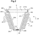
- FIG. 2 there is shown more precisely the device 20 for generating images of the head-up display 1 in section.
- This image generation device 20 here comprises at least one light source 23, a screen 21 backlit by this light source 23, and a reflector 25.
- the image generation device 20 actually comprises a plurality of light sources 23 mounted on a support 24.
- the light sources 23 are here aligned perpendicular to the section plane of the figure 2 .
- each light source 23 is here a light emitting diode (or LED for “Light Emitting Diode”), and all of these LEDs are mounted on a printed circuit playing the role of support 24.
- the LEDs in the form of a single row of a plurality of light sources 23, here comprising four light sources 23.
- the plurality of light sources comprise between two and twenty light sources, for example arranged in one or two rows.
- the light sources 23 are here adapted to backlight the screen 21, said screen 21 being placed at a distance from them. In other words, the screen 21 is illuminated on its rear face by the light sources 23.
- the screen 21 is a liquid crystal screen (or LCD for “Liquid Crystal Display”), for example with thin-film transistors (or TFT for “Thin-Film Transistor”).
- It comprises a matrix of variable transmittance elements suitable for forming the pixels of an image to be displayed when they are backlit by the light sources 23.
- the screen 21 has a generally flat front face 211A.
- the reflector 25 is disposed between the light sources 23 and the screen 21 so as to at least partially reflect the light emitted by the light sources 23 towards the screen 21.
- the reflector 25 extends along a main axis X of extension and comprises a reflection portion 250.
- the reflecting portion 250 has a generally flared, or frustoconical, shape from the light sources towards the screen 21.
- it comprises four walls 251 facing each other in pairs, and which extend slightly obliquely with respect to the main axis X of extension, from the light sources 23 towards the screen 21.
- the four walls 251 are flat.
- the walls can take any form particularly suitable for reflecting the maximum amount of light towards the screen.
- the four walls 251 are contiguous so that the reflecting portion 250 has, at one end, a first opening where the light sources 23 are housed, and, at the other end, a second opening (surface greater than that of the first opening) on the side of which the screen 21 is placed.
- the internal face 25A of the reflection portion 250 of the reflector 25 has a high reflection coefficient. It may for example be white in color so as to generate a diffuse reflection. As a variant, it can be covered with a reflective layer (for example of chromium or aluminum) so as to generate a specular reflection.
- a reflective layer for example of chromium or aluminum
- both the shape and the material of the internal face of the reflector 25 are here adapted to reflect all of the light rays emitted by the light sources 23 towards the screen 21.
- the reflector 25 defines a housing 280 designed to receive the screen 21 so that said reflector 25 has a zone of thermal contact 290 with said screen 21.
- the reflector 25 comprises for this purpose a support portion 255 adapted to support and house the screen 21, and to create thermal contact with the latter.
- the screen support portion 255 extends from the second opening of the reflecting portion 250 of the reflector 25.
- each wall 251 of the reflecting portion 250 of the reflector 25 is here extended by a flat 252 which extends outwardly from said reflector 25.
- the flats extend in a plane generally parallel to the support 24 of the light sources 23.
- the flats 252 are adapted to accommodate the screen 21, as shown in figure 2 .
- Each flat 252 is itself extended by a flange 254, which extends generally perpendicular to said corresponding flat 252, away from the light sources 23.
- each flange 254 is here generally parallel to the main axis X of extension of the reflector 25.
- the support portion 255 of the reflector 25 is thus formed by the four flats 252 and by the four flanges 254 extending the four walls 251.
- the support portion 255 thus defines the housing 280 for receiving the screen 21.
- edges 254 of the support portion 255 surround the screen 21 by forming a frame around said screen 21 when the latter is in contact with the flats 252 of said reflector 25.
- the screen 21 is integrated into the reflector 25, which saves space for the head-up display 1.
- the image generation device is thus more easily integrated into a device. motor vehicle dashboard.
- the reflector 25 is closed, on one side by the screen 21, and on the other side by the light sources 23 (namely in practice by the support 24 of the light sources 23).
- the image generation device 20 forms a closed enclosure.
- the internal elements of the image generation device are then protected from dust or other external attacks.
- the closed enclosure also ensures that no parasitic rays will be emitted from the light sources 23 directly in the direction of the other elements of the head-up display 1.
- the folding mirror 30 and / or the semi-transparent plate 10 will only receive from the image generation device 20 the rays which have passed through the screen 21.
- the thermal contact zone 290 between the screen 21 and the reflector 25 is located on a periphery of at least one of the faces of said screen 21.
- the thermal contact zone 290 is located over the entire periphery of the rear face of the screen 21.
- this makes it possible to more easily transmit to the reflector 25 the heat accumulated in said screen 21, this heat being first accumulated. on the rear face of the screen 21 since it comes from the flow of light backlit the screen 21.
- the thermal contact zone 290 is here located at the level of the flats 252 of the reflector 25, the latter being in thermal contact with the rear face of the screen 21.
- the screen 21 is in direct contact with the support portion 255 of the reflector 25.
- the thermal contact to be physical contact between the screen 21 and the reflector 25.
- the screen 21 and the flats 252 of the support portion 255 of the reflector 25 are designed to be perfectly contiguous, that is to say to be in physical contact, without an air layer intermediate.
- an outer face 25B of said reflector 25 is provided with a plurality of fins 26 for heat dissipation.
- the reflector 25 serves as a heat sink (or radiator) for the screen 21 insofar as it is adapted to remove the heat which is accumulated in the screen 21 (this heat being due to absorption, by the screen, part of the light backlit it).
- the heat dissipation fins 26 are located on the external face 25B of the reflector 25 so as to cover at least 15% of this external face 25B.
- the heat dissipation fins 26 are located on the outer face 25B of the reflector 25 so as to cover at least 30% of this outer face 25B.
- the heat dissipation fins 26 are here grouped together in at least two packages of fins on the external face 25B of the reflector 25. In each package of fins, the heat dissipation fins 26 are separated from each other by a thin layer of air. Here, the distance separating two consecutive packets is greater than the distance separating two consecutive fins 26 of the same pack.
- the heat dissipation fins 26 extend here over the entire height of the reflector 25. They are distributed over all four walls 251 of the reflecting portion 250 of the reflector 25.
- each pack of fins 26 takes the form of a column of fins 26.
- the reflector 25 here comprises four columns of fins. These columns are distributed face to face on each wall 251 of the reflector 25.
- the fins form columns distributed in staggered rows on the external face of the reflector.
- the fins are distributed individually randomly on the outer face of the reflector. In this variant, we no longer speak of packets of fins.
- the heat dissipating fins 26 each extend in a direction generally perpendicular to the main extension axis X of the reflector 25, parallel to each other.
- each fin 26 is optimized to minimize the bulk of the reflector while maximizing contact with the air surrounding the reflector 25.
- the contact surface of the air with the reflector 25 is enlarged.
- the heat contained in the screen 21 is capable of being discharged into the air by means of the reflector 25.
- the reflector 25 is adapted to drain the heat contained in. the screen 21 and to distribute this heat over its entire surface, that is to say in the four walls 251 and in the plurality of fins 26 that it comprises.
- the heat dissipation fins 26 being in contact with the air, the heat can then be evacuated into the air, by conduction and / or radiation, then optionally by convection.
- the fins 26 and the reflector 25 are in one piece. More precisely, here, the fins 26 and the reflector 25 are in one piece.
- the reflector 25 can support the screen 21 while ensuring efficient thermal conduction
- the reflector 25 (here provided with its heat dissipation fins 26) is made of a material that is both rigid and a good conductor of heat (material with a thermal conductivity greater than 1 Wm -1 .K -1 and preferably greater than 10 Wm -1 .K -1 ), that is to say suitable for draining heat from the screen 21 to the walls 251 of the reflector 25.
- the reflector 25 (provided in the example described with its heat dissipation fins 26) is made of a metallic material such as a metallic alloy, for example of aluminum (having a thermal conductivity greater than 200 Wm -1 .K -1 , generally of the order of 230 Wm -1 .K -1 ) or in Zamak (also called Zamac).
- a metallic material such as a metallic alloy, for example of aluminum (having a thermal conductivity greater than 200 Wm -1 .K -1 , generally of the order of 230 Wm -1 .K -1 ) or in Zamak (also called Zamac).
- the reflector (possibly provided with its heat dissipation fins) can be made of a rigid polymer material (preferably having a thermal conductivity greater than 10 Wm -1 .K -1 ), for example a filled polymer material such as Makrolon TC8030 (thermally conductive polycarbonate).
- charged polymer is understood to mean a polymer-based composite material (for example polycarbonate) also comprising an additional material making it possible to obtain good thermal conductivity (typically a thermal conductivity greater than 1 Wm ⁇ 1 .K ⁇ 1 , or even 10 Wm - 1.K -1 ).
- the reflector 25, optionally provided with heat dissipation fins 26, effectively cools the screen 21 and / or prevents the heating of said screen 21.
- the driver of the vehicle can then obtain the level of brightness that he wishes for. the virtual image seen thanks to the semi-transparent slide 10.
- the reflector 25, provided with its support portion 255 and its heat dissipation fins 26, is manufactured by molding.
- each wall 251 is molded with, on its external face, the heat dissipation fins 26 distributed in at least one column, and at its widest end, the flat 252 extended by the rim 254.
- Each wall 251 then forms a single piece with the fins 26, the flat 252 and the corresponding rim 254.
- the walls 251 are then assembled together in a contiguous manner to form the reflector 25.
- Such an assembly is produced by gluing or by welding depending on the material used to mold the walls.
- the internal face 25A of the reflector 25 can then be painted or covered with a reflective layer.
- each wall is molded without the fins, only with the flat area extended by the rim.
- the walls would then be assembled together, and the fins glued, using an adhesive suitable for transmitting heat, or welded, to the external face of the reflector.
- the reflector provided with its walls, its heat dissipation fins and its support portion is produced in a single piece, thanks to a suitable mold into which said material is injected which is rigid and a good conductor of heat.
- the reflector 25 thus obtained is therefore suitable for fulfilling several functions, namely, its primary function of reflector, that of screen support and also that of thermal radiator.
- a heat dissipating radiator is for example a fan. It is also possible, in particular when using a technique for directly mounting the chip (or “ On Chip Board ”), using, as a support, the heat sink usually associated with light sources.
- the reflector and the support are in thermal contact, so that the heat dissipating radiator of the light sources is also suitable for dissipating the heat from the reflector, in addition to the fins.
- the combined effect of the heat dissipating reflector and heat sink further improves the cooling of the display.
- provision can be made to thermally insulate the support from the light sources and the reflector, so that the support cannot transmit heat to the reflector, and vice versa.
- each flange of the support portion of the reflector is extended by a second flat, extending parallel to the first flat already provided.
- the screen would be sandwiched between the two flats and the rim, and the thermal contact zone between the screen and the reflector would be enlarged.
Landscapes
- Physics & Mathematics (AREA)
- General Physics & Mathematics (AREA)
- Optics & Photonics (AREA)
- Nonlinear Science (AREA)
- Chemical & Material Sciences (AREA)
- Engineering & Computer Science (AREA)
- Mathematical Physics (AREA)
- Crystallography & Structural Chemistry (AREA)
- Combustion & Propulsion (AREA)
- Transportation (AREA)
- Mechanical Engineering (AREA)
- Instrument Panels (AREA)
Description
- La présente invention concerne de manière générale le domaine des afficheurs tête haute pour véhicule.
- Elle concerne plus particulièrement un dispositif de génération d'images pour afficheur tête haute comprenant au moins une source de lumière, un écran adapté à être rétroéclairé par ladite source de lumière, et un réflecteur, disposé entre ladite source de lumière et ledit écran, et adapté à réfléchir au moins en partie la lumière émise par la source de lumière.
- Le principe des afficheurs tête haute pour véhicule est de projeter des images, notamment utiles à la conduite, directement dans le champ de vision d'un conducteur.
- Pour cela, les afficheurs tête haute comprennent en général un dispositif de génération d'images adapté à générer des images et un dispositif de projection des images générées adapté à transmettre ces images vers une lame semi-transparente placée dans le champ de vision du conducteur.
- La plupart des dispositifs de génération d'images utilisés aujourd'hui comprennent une source de lumière rétroéclairant un écran adapté à générer les images. Cet écran absorbe une partie de la lumière qui le rétroéclaire, ce qui provoque son échauffement thermique.
- Or, la température de l'écran est critique pour son bon fonctionnement, ce dernier risquant d'être endommagé, voire d'être rendu défectueux, par une température trop élevée. L'échauffement de l'écran peut par conséquent réduire sa durée de vie et conduire à son remplacement.
- Il est donc nécessaire de trouver des solutions visant à refroidir l'écran, ou à éviter son échauffement.
- On sait que la température de l'écran est en grande partie liée à l'échauffement créé par la source de lumière qui le rétroéclaire.
- On connaît ainsi une première solution consistant à placer une sonde de température dans le dispositif de génération d'images, cette sonde étant adaptée à contrôler la température de l'écran et à réguler automatiquement, en fonction de cette température, la puissance générée par la source de lumière.
- Cette première solution présente un inconvénient majeur en ce que l'utilisateur n'obtient pas toujours un affichage avec le niveau de luminosité souhaité puisque la source de lumière peut être amenée à fonctionner à puissance réduite.
- En outre, du fait de la sonde, cette première solution n'est pas optimale en termes d'encombrement du dispositif de génération d'images.
- On connaît également une deuxième solution consistant à ouvrir, au moins partiellement, le dispositif de génération d'images afin d'évacuer la chaleur générée par le rayonnement lumineux de la source de lumière.
- Néanmoins, cette deuxième solution ne garantit pas l'étanchéité du dispositif de génération d'images aux poussières. Ainsi, les optiques contenues dans le dispositif de génération d'images sont exposées aux poussières et risquent d'être détériorées.
- En outre, cette deuxième solution implique que des fuites de lumière sont possibles depuis la source de lumière vers les autres éléments de l'afficheur tête haute. D'éventuels rayons parasites peuvent ainsi être générés dans l'ensemble de l'afficheur tête haute et la qualité finale de l'image générée est affectée. Le document
WO 2015/159030 propose également une solution d'évacuation de la chaleur générée par la source lumineuse. - Afin de remédier aux inconvénients précités de l'état de la technique, la présente invention propose un dispositif de génération d'images conçu pour refroidir l'écran qu'il comprend et/ou éviter l'échauffement dudit écran.
- Plus particulièrement, on propose selon l'invention un dispositif de génération d'images (pour afficheur tête haute) comprenant au moins une source de lumière, un écran adapté à être rétroéclairé par ladite source de lumière, et un réflecteur disposé entre ladite source de lumière et ledit écran de sorte qu'une face interne dudit réflecteur réfléchisse au moins en partie la lumière émise par la source de lumière, dans lequel le réflecteur présente une conductivité thermique supérieure à 1 W.m-1.K-1.
- Ainsi, le réflecteur est adapté à évacuer, par effet de conduction thermique, un surplus de chaleur du dispositif de génération d'images, par exemple vers des éléments de dissipation thermique tels que des ailettes de dissipation thermique, comme proposé plus loin.
- En outre, de manière avantageuse, le réflecteur définit un logement conçu pour recevoir l'écran de sorte que ledit réflecteur présente une zone de contact thermique avec ledit écran.
- Ainsi, le réflecteur étant en contact thermique avec l'écran, il est tout particulièrement adapté à conduire et/ou à dissiper la chaleur contenue dans l'écran.
- En outre, le réflecteur définissant un logement de réception de l'écran, il permet un gain de place du dispositif de génération d'images.
- D'autres caractéristiques non limitatives et avantageuses du dispositif conforme à l'invention sont les suivantes :
- le réflecteur s'étend selon un axe principal d'extension et comporte une portion de réflexion et une portion de support ;
- la portion de support définit ledit logement conçu pour recevoir l'écran et comporte un méplat et un rebord qui s'élève à partir dudit méplat de manière à entourer l'écran ;
- ledit méplat forme au moins en partie la zone de contact thermique avec l'écran ;
- ledit écran est directement en contact avec le réflecteur ;
- le réflecteur est fermé d'un côté par ledit écran, de l'autre par (un support de) la source de lumière, de sorte que ledit dispositif de génération d'images forme une enceinte close ;
- une face externe du réflecteur est pourvue d'une pluralité d'ailettes de dissipation thermique ;
- les ailettes de dissipation thermique et le réflecteur sont en une seule pièce ;
- le réflecteur, et éventuellement les ailettes de dissipation thermique, sont réalisés en un matériau métallique ;
- le réflecteur, et éventuellement les ailettes de dissipation thermique, sont réalisés en un matériau polymère, par exemple un matériau polymère chargé ;
- les ailettes de dissipation thermique couvrent au moins 15% de ladite face externe du réflecteur ;
- les ailettes de dissipation thermique couvrent au moins 30% de ladite face externe du réflecteur ;
- les ailettes de dissipation thermique s'étendent sur toute la hauteur de la portion de réflexion du réflecteur ;
- les ailettes de dissipation thermique s'étendent chacune dans une direction globalement perpendiculaire à l'axe principal d'extension du réflecteur, parallèlement les unes par rapport aux autres ;
- les ailettes de dissipation thermique sont agencées selon une pluralité de colonnes de dissipation thermique ;
- le réflecteur présente une conductivité thermique supérieure à 10 W.m-1.K-1;
- il est prévu un radiateur thermique disposé à l'arrière de la source de lumière ;
- il est prévu d'isoler thermiquement le réflecteur et un support de la source de lumière.
- L'invention propose également un afficheur tête haute comprenant un dispositif de génération d'images tel que décrit précédemment et un dispositif de projection d'images adapté à transmettre en direction d'une lame semi-transparente les images générées par le dispositif de génération d'images.
- Dans l'afficheur tête haute conforme à l'invention, le dispositif de projection d'images comprend un miroir agencé de manière à réfléchir en direction de la lame semi-transparente les images générées par le dispositif de génération d'images.
- La description qui va suivre en regard des dessins annexés, donnés à titre d'exemples non limitatifs, fera bien comprendre en quoi consiste l'invention et comment elle peut être réalisée.
- Sur les dessins annexés :
- la
figure 1 est une représentation schématique d'un afficheur tête haute selon l'invention en position dans le véhicule ; et, - la
figure 2 est une représentation schématique en coupe d'un dispositif de génération d'images selon l'invention. - Dans la suite de la description, les termes « avant » et « arrière » seront utilisés pour désigner les éléments en position dans le véhicule automobile, par rapport à la direction longitudinale dudit véhicule automobile. L'avant désignera le côté d'un élément dirigé vers le conducteur, autrement dit le côté tourné vers le coffre, et l'arrière désignera le côté de cet élément tourné vers le capot.
- Sur la
figure 1 , on a représenté les éléments principaux d'un afficheur 1 tête haute destiné à équiper un véhicule, par exemple un véhicule automobile. - Un tel afficheur 1 est adapté à créer une image virtuelle I dans le champ de vision d'un conducteur du véhicule, de sorte que le conducteur puisse voir cette image virtuelle I et les informations éventuelles qu'elle contient sans avoir à détourner le regard de la route.
- A cet effet, l'afficheur 1 comprend une lame semi-transparente 10 placée dans le champ de vision du conducteur (voir
figure 1 ), un dispositif de génération d'images 20 adapté à générer des images et un dispositif de projection 30 d'images adapté à transmettre en direction de ladite lame semi-transparente 10 les images générées par l'unité de génération d'images 20. - Plus précisément, la lame semi-transparente 10 est ici un combineur 10, c'est-à-dire une lame semi-transparente dédiée à l'afficheur tête haute 1.
- Un tel combineur 10 est ici placé entre le parebrise 2 du véhicule et les yeux du conducteur.
- En variante, la lame semi-transparente peut être confondue avec le parebrise du véhicule. Autrement dit, dans cette variante, c'est le parebrise du véhicule qui a la fonction de lame-semi transparente pour l'afficheur tête haute.
- Par ailleurs, ici, le dispositif de projection 30 d'images comprend un miroir de repliement agencé de manière à réfléchir les images générées par le dispositif de génération 20 d'images en direction de la lame semi-transparente 10. Ici, ledit miroir de repliement est un miroir plan.
- En variante, le dispositif de projection d'images peut comprendre une pluralité de miroirs et/ou d'autres éléments optiques tels qu'une lentille par exemple.
- Sur la
figure 2 , on a représenté plus précisément le dispositif de génération 20 d'images de l'afficheur tête haute 1 en coupe. - Ce dispositif de génération 20 d'images comprend ici au moins une source de lumière 23, un écran 21 rétroéclairé par cette source de lumière 23, et un réflecteur 25.
- Dans l'exemple représenté, le dispositif de génération 20 d'images comprend en réalité une pluralité de sources de lumière 23 montées sur un support 24.
- Les sources de lumières 23 sont ici alignées perpendiculairement au plan de coupe de la
figure 2 . - Plus précisément, chaque source de lumière 23 est ici une diode électroluminescente (ou LED pour « Light Emitting Diode »), et l'ensemble de ces LEDs est monté sur un circuit imprimé jouant le rôle de support 24.
- On propose ici de disposer les LEDs sous forme d'une unique rangée d'une pluralité de sources de lumière 23, comprenant ici quatre sources de lumière 23. En variante, on peut par exemple envisager que la pluralité de sources de lumière comprenne entre deux et vingt sources de lumière, par exemple disposées sur une ou deux rangées.
- Les sources de lumières 23 sont ici adaptées à rétroéclairer l'écran 21, ledit écran 21 étant placé à distance d'elles. Autrement dit, l'écran 21 est éclairé, sur sa face arrière par les sources de lumière 23.
- Dans l'exemple de réalisation proposé, l'écran 21 est un écran à cristaux liquides (ou LCD pour "Liquid Crystal Display"), par exemple à transistors en couche mince (ou TFT pour "Thin-Film Transistor").
- Il comprend une matrice d'éléments de transmittance variable adaptés à former les pixels d'une image à afficher lorsqu'ils sont rétroéclairés par les sources de lumière 23.
- Ici, l'écran 21 comporte une face avant 211A globalement plane.
- Le réflecteur 25 est disposé entre les sources de lumière 23 et l'écran 21 de manière à réfléchir au moins en partie la lumière émise par les sources de lumière 23 en direction de l'écran 21.
- En pratique, le réflecteur 25 s'étend selon un axe principal X d'extension et comporte une portion de réflexion 250.
- La portion de réflexion 250 présente une forme globalement évasée, ou tronconique, depuis les sources de lumière vers l'écran 21.
- Elle comporte à cet effet quatre parois 251 se faisant face deux à deux, et qui s'étendent légèrement à l'oblique par rapport à l'axe principal X d'extension, depuis les sources de lumière 23 vers l'écran 21.
- Dans l'exemple représenté ici, les quatre parois 251 sont planes. En variante, les parois peuvent prendre toute forme particulièrement adaptée à réfléchir le maximum de lumière vers l'écran.
- Les quatre parois 251 sont jointives de sorte que la portion de réflexion 250 présente, à une extrémité, une première ouverture où sont logées les sources de lumière 23, et, à l'autre extrémité, une deuxième ouverture (de surface supérieure à celle de la première ouverture) du côté de laquelle est placé l'écran 21.
- En pratique, c'est une face interne 25A du réflecteur 25 qui réfléchit au moins en partie la lumière émise par les sources de lumière 23.
- A cet effet, la face interne 25A de la portion de réflexion 250 du réflecteur 25 présente un coefficient de réflexion élevé. Elle peut par exemple être de couleur blanche de manière à engendrer une réflexion diffuse. Elle peut en variante être recouverte d'une couche réfléchissante (par exemple de chrome ou d'aluminium) de manière à engendrer une réflexion spéculaire.
- Ainsi, tant la forme que le matériau de la face interne du réflecteur 25 sont ici adaptés à réfléchir l'ensemble des rayons lumineux émis par les sources de lumière 23 en direction de l'écran 21.
- En outre, de manière avantageuse, le réflecteur 25 définit un logement 280 conçu pour recevoir l'écran 21 de sorte que ledit réflecteur 25 présente une zone de contact thermique 290 avec ledit écran 21.
- Le réflecteur 25 comporte à cet effet une portion de support 255 adaptée à supporter et loger l'écran 21, et à créer un contact thermique avec ce dernier.
- En pratique, la portion de support 255 d'écran s'étend à partir de la deuxième ouverture de la portion de réflexion 250 du réflecteur 25.
- Plus précisément, chaque paroi 251 de la portion de réflexion 250 du réflecteur 25 est ici prolongée par un méplat 252 qui s'étend vers l'extérieur dudit réflecteur 25. Ici, les méplats s'étendent dans un plan globalement parallèle au support 24 des sources de lumière 23.
- Les méplats 252 sont adaptés à accueillir l'écran 21, tel que cela est représenté en
figure 2 . - Chaque méplat 252 est lui-même prolongé par un rebord 254, qui s'étend globalement perpendiculairement audit méplat 252 correspondant, en s'éloignant des sources de lumière 23.
- Ainsi, chaque rebord 254 est ici globalement parallèle à l'axe principal X d'extension du réflecteur 25.
- La portion de support 255 du réflecteur 25 est ainsi formée par les quatre méplats 252 et par les quatre rebords 254 prolongeant les quatre parois 251.
- La portion de support 255 définit ainsi le logement 280 de réception de l'écran 21.
- Plus précisément, les rebords 254 de la portion de support 255 entourent l'écran 21 en formant un cadre autour dudit écran 21 lorsque ce dernier est au contact des méplats 252 dudit réflecteur 25.
- Grâce à la portion de support 255 du réflecteur 25, l'écran 21 est intégré au réflecteur 25, ce qui engendre un gain de place pour l'afficheur tête haute 1. Le dispositif de génération d'images est ainsi plus facilement intégrable dans une planche de bord de véhicule automobile.
- De manière avantageuse, le réflecteur 25 est fermé, d'un côté par l'écran 21, et de l'autre côté par les sources de lumière 23 (à savoir en pratique par le support 24 des sources de lumière 23).
- Ainsi, le dispositif de génération 20 d'images forme une enceinte close.
- Avantageusement, les éléments internes du dispositif de génération d'images sont alors protégés des poussières ou autres agressions extérieures.
- L'enceinte close assure également qu'aucun rayon parasite ne sera émis depuis les sources de lumière 23 directement en direction des autres éléments de l'afficheur tête haute 1. Autrement dit, le miroir de repliement 30 et/ou la lame semi-transparente 10 ne recevront du dispositif de génération 20 d'images que les rayons ayant traversé l'écran 21.
- La zone de contact thermique 290 entre l'écran 21 et le réflecteur 25 est située sur une périphérie d'au moins une des faces dudit écran 21.
- Ici, la zone de contact thermique 290 est située sur toute la périphérie de la face arrière de l'écran 21. Avantageusement, cela permet de transmettre plus facilement au réflecteur 25 la chaleur accumulée dans ledit écran 21, cette chaleur étant d'abord accumulée sur la face arrière de l'écran 21 puisqu'elle provient du flux de lumière rétroéclairant l'écran 21.
- En pratique, la zone de contact thermique 290 est ici située au niveau des méplats 252 du réflecteur 25, ces derniers étant en contact thermique avec la face arrière de l'écran 21.
- Ici, l'écran 21 est directement en contact avec la portion de support 255 du réflecteur 25.
- Autrement dit, on prévoit ici que le contact thermique soit un contact physique entre l'écran 21 et le réflecteur 25. A cet effet, l'écran 21 et les méplats 252 de la portion de support 255 du réflecteur 25 sont prévus pour être parfaitement jointifs, c'est-à-dire pour être en contact physique, sans couche d'air intermédiaire.
- En variante, on peut prévoir que l'écran et le réflecteur soient en contact thermique par l'intermédiaire d'un pont thermique.
- En outre, de manière remarquable, une face externe 25B dudit réflecteur 25 est pourvue d'une pluralité d'ailettes 26 de dissipation thermique.
- Ainsi, avantageusement, le réflecteur 25 sert de dissipateur (ou radiateur) thermique à l'écran 21 dans la mesure où il est adapté à évacuer la chaleur qui est accumulée dans l'écran 21 (cette chaleur étant due à l'absorption, par l'écran, d'une partie de la lumière le rétroéclairant).
- Les ailettes 26 de dissipation thermique sont implantées sur la face externe 25B de réflecteur 25 de manière à couvrir au moins 15% de cette face externe 25B.
- Autrement dit, si les ailettes 26 de dissipation thermique étaient toutes regroupées de façon contigüe, dans une unique région de la face externe 25B du réflecteur 25, cette région représenterait au moins 15% de la face externe 25B totale du réflecteur 25.
- De préférence, les ailettes 26 de dissipation thermique sont implantées sur la face externe 25B du réflecteur 25 de manière à couvrir au moins 30% de cette face externe 25B.
- Plus précisément, les ailettes 26 de dissipation thermique sont ici regroupées en au moins deux paquets d'ailettes sur la face externe 25B du réflecteur 25. Dans chaque paquet d'ailettes, les ailettes 26 de dissipation thermique sont séparées les unes des autres par une fine couche d'air. Ici, la distance séparant deux paquets consécutifs est supérieure à la distance séparant deux ailettes 26 consécutives d'un même paquet.
- En pratique, les ailettes 26 de dissipation thermique s'étendent ici sur toute la hauteur du réflecteur 25. Elles sont réparties sur l'ensemble des quatre parois 251 de la portion de réflexion 250 du réflecteur 25.
- Selon le mode de réalisation présenté sur la
figure 2 , chaque paquet d'ailettes 26 prend la forme d'une colonne d'ailettes 26. Le réflecteur 25 comprend ici quatre colonnes d'ailettes. Ces colonnes sont réparties face à face sur chaque paroi 251 du réflecteur 25. En variante, on peut envisager que les ailettes forment des colonnes réparties en quinconce sur la face externe du réflecteur. - En variante, on peut envisager que les ailettes soient réparties individuellement de façon aléatoire sur la face externe du réflecteur. Dans cette variante, on ne parle alors plus de paquets d'ailettes.
- Ici, les ailettes 26 de dissipation thermique s'étendent chacune dans une direction globalement perpendiculaire à l'axe principal X d'extension du réflecteur 25, parallèlement les unes par rapport aux autres.
- La surface de chaque ailette 26 est optimisée pour minimiser l'encombrement du réflecteur tout en maximisant le contact avec l'air entourant le réflecteur 25.
- Avantageusement, grâce aux ailettes 26, la surface de contact de l'air avec le réflecteur 25 est agrandie.
- Ainsi, par un effet de conduction thermique, la chaleur contenue dans l'écran 21 est susceptible d'être évacuée dans l'air par l'intermédiaire du réflecteur 25. Pour ce faire, le réflecteur 25 est adapté à drainer la chaleur contenue dans l'écran 21 et à répartir cette chaleur sur toute sa surface, c'est-à-dire dans les quatre parois 251 et dans la pluralité d'ailettes 26 qu'il comprend. Les ailettes 26 de dissipation thermique étant en contact avec l'air, la chaleur peut ensuite être évacuée dans l'air, par conduction et/ou rayonnement, puis éventuellement par convection.
- En pratique, les ailettes 26 et le réflecteur 25 sont d'un seul tenant. Plus précisément, ici, les ailettes 26 et le réflecteur 25 sont en une seule pièce.
- Pour que le réflecteur 25 puisse supporter l'écran 21 tout en assurant une conduction thermique efficace, le réflecteur 25 (ici muni de ses ailettes 26 de dissipation thermique) est réalisé en un matériau à la fois rigide et bon conducteur de chaleur (matériau avec une conductivité thermique supérieure à 1 W.m-1.K-1 et de préférence supérieure à 10 W.m-1.K-1), c'est-à-dire adapté à drainer la chaleur depuis l'écran 21 vers les parois 251 du réflecteur 25.
- Ainsi, ici, le réflecteur 25 (muni dans l'exemple décrit de ses ailettes 26 de dissipation thermique) est réalisé en un matériau métallique tel qu'un alliage métallique, par exemple en Aluminium (ayant une conductivité thermique supérieure à 200 W.m-1.K-1, généralement de l'ordre de 230 W.m-1.K-1) ou en Zamak (aussi appelé Zamac).
- En variante, le réflecteur (éventuellement muni de ses ailettes de dissipation thermique) peut être réalisé en un matériau polymère rigide (ayant de préférence une conductivité thermique supérieure à 10 W.m-1.K-1), par exemple un matériau polymère chargé tel que le Makrolon TC8030 (polycarbonate thermo-conducteur).
- On entend par polymère chargé un matériau composite à base de polymère (par exemple polycarbonate) comprenant également un matériau complémentaire permettant d'obtenir une bonne conductivité thermique (typiquement une conductivité thermique supérieure à 1 W.m-1.K-1, voire à 10 W.m-1.K-1).
- Ainsi, le réflecteur 25, éventuellement muni des ailettes 26 de dissipation thermique, permet de refroidir efficacement l'écran 21 et/ou évite l'échauffement dudit écran 21. Le conducteur du véhicule peut alors obtenir le niveau de luminosité qu'il désire pour l'image virtuelle vue grâce à la lame semi-transparente 10.
- En pratique, le réflecteur 25, muni de sa portion de support 255 et de ses ailettes 26 de dissipation thermique, est fabriqué par moulage.
- Plus précisément, chaque paroi 251 est moulée avec, sur sa face externe, les ailettes 26 de dissipation thermique répartie en au moins une colonne, et à son extrémité la plus large, le méplat 252 prolongé par le rebord 254.
- Chaque paroi 251 forme alors une seule pièce avec les ailettes 26, le méplat 252 et le rebord 254 correspondants.
- Les parois 251 sont ensuite assemblées entre elles de façon jointive pour former le réflecteur 25. Un tel assemblage est réalisé par collage ou par soudage selon le matériau utilisé pour mouler les parois.
- La face interne 25A du réflecteur 25 peut ensuite être peinte ou recouverte d'une couche réfléchissante.
- En variante, on peut envisager que chaque paroi soit moulée sans les ailettes, uniquement avec le méplat prolongé par le rebord. Les parois seraient ensuite assemblées entre elles, et les ailettes collées, à l'aide d'une colle adaptée à transmettre la chaleur, ou soudées, à la face externe du réflecteur.
- En variante encore, le réflecteur muni de ses parois, de ses ailettes de dissipation thermique et de sa portion de support, est réalisé en une seule pièce, grâce à un moule adapté dans lequel on injecte ledit matériau rigide et bon conducteur de chaleur.
- Le réflecteur 25 ainsi obtenu est donc adapté à remplir plusieurs fonctions, à savoir, sa fonction première de réflecteur, celle de support d'écran et également celle de radiateur thermique.
- En variante, on peut prévoir d'ajouter au dispositif de génération d'images un radiateur à dissipation thermique placé à l'arrière du support des sources de lumière, de manière à dissiper en partie la chaleur générée par lesdites sources de lumière. Un tel radiateur à dissipation thermique est par exemple un ventilateur. On peut également, notamment lorsqu'on utilise une technique de montage direct de la puce (ou « On Chip Board »), utiliser, en tant que support, le dissipateur thermique usuellement associé aux sources de lumière.
- Avantageusement, dans cette variante, le réflecteur et le support sont en contact thermique, de sorte que le radiateur à dissipation thermique des sources de lumière est également adapté à dissiper la chaleur du réflecteur, en sus des ailettes. L'effet combiné du réflecteur et du radiateur à dissipation thermique permet d'améliorer encore le refroidissement de l'écran.
- En variante encore, on peut prévoir d'isoler thermiquement le support des sources de lumière et le réflecteur, de sorte que le support ne puisse pas transmettre de chaleur au réflecteur, et inversement.
- Selon une autre variante, on peut envisager que chaque rebord de la portion de support du réflecteur soit prolongé par un deuxième méplat, s'étendant parallèlement au premier méplat déjà prévu. Ainsi, l'écran serait pris en sandwich entre les deux méplats et le rebord, et la zone de contact thermique entre l'écran et le réflecteur serait agrandie.
Claims (12)
- Dispositif de génération (20) d'images comprenant :- au moins une source de lumière (23),- un écran (21) adapté à être rétroéclairé par ladite source de lumière (23), et- un réflecteur (25) disposé entre ladite source de lumière (23) et ledit écran (21) de sorte qu'une face interne (25A) dudit réflecteur (25) réfléchisse au moins en partie la lumière émise par la source de lumière (23),caractérisé en ce que le réflecteur (25) présente une conductivité thermique supérieure à 1 W.m-1.K-1.
- Dispositif de génération (20) d'images selon la revendication 1, dans lequel le réflecteur (25) définit en outre un logement (280) conçu pour recevoir l'écran (21) de sorte que ledit réflecteur (25) présente une zone de contact thermique (290) avec ledit écran.
- Dispositif de génération (20) d'images selon la revendication 2, dans lequel le réflecteur (25) s'étend selon un axe principal (X) d'extension et comporte une portion de réflexion (250) et une portion de support (255), ladite portion de support (255) définissant ledit logement (280) conçu pour recevoir l'écran (21) et comportant :- un méplat (252) formant au moins en partie la zone de contact thermique (290) avec l'écran (21), et- un rebord (254) qui s'élève à partir dudit méplat (252) de manière à entourer l'écran (21).
- Dispositif de génération (20) d'images selon l'une des revendications 1 à 3, dans lequel ledit écran (21) est directement en contact avec le réflecteur (25).
- Dispositif de génération (20) d'images selon l'une des revendications 1 à 4, dans lequel le réflecteur (25) est fermé d'un côté par ledit écran (21), de l'autre par un support (24) de la source de lumière (23), de sorte que ledit dispositif de génération (20) d'images forme une enceinte close.
- Dispositif de génération (20) d'images selon l'une des revendications 1 à 5, dans lequel une face externe (25B) dudit réflecteur (25) est pourvue d'une pluralité d'ailettes (26) de dissipation thermique.
- Dispositif de génération d'images selon la revendication 6, dans lequel les ailettes (26) de dissipation thermique et le réflecteur (25) sont en une seule pièce.
- Dispositif de génération (20) d'images selon la revendications 6 ou 7, dans lequel les ailettes (26) de dissipation thermique couvrent au moins 15% de ladite face externe (25B) du réflecteur (25)
- Dispositif de génération (20) d'images selon l'une des revendications 1 à 8, dans lequel le réflecteur (25) est réalisé en un matériau métallique.
- Dispositif de génération (20) d'images selon l'une des revendications 1 à 8, dans lequel le réflecteur (25) est réalisé en un matériau polymère chargé.
- Afficheur tête haute (1) comprenant un dispositif de génération (20) d'images selon l'une des revendications 1 à 10 et un dispositif de projection (30) d'images adapté à transmettre en direction d'une lame semi-transparente (10) les images générées par le dispositif de génération (20) d'images.
- Afficheur tête haute (1) selon la revendication 11, dans lequel le dispositif de projection (30) d'images comprend un miroir (30) agencé de manière à réfléchir en direction de la lame semi-transparente (10) les images générées par le dispositif de génération (20) d'images.
Applications Claiming Priority (2)
| Application Number | Priority Date | Filing Date | Title |
|---|---|---|---|
| FR1656141A FR3054046B1 (fr) | 2016-06-29 | 2016-06-29 | Dispositif de generation d'images et afficheur tete haute associe |
| PCT/EP2017/066073 WO2018002188A1 (fr) | 2016-06-29 | 2017-06-28 | Dispositif de génération d'images et afficheur tête haute associé |
Publications (2)
| Publication Number | Publication Date |
|---|---|
| EP3491444A1 EP3491444A1 (fr) | 2019-06-05 |
| EP3491444B1 true EP3491444B1 (fr) | 2021-08-04 |
Family
ID=56611499
Family Applications (1)
| Application Number | Title | Priority Date | Filing Date |
|---|---|---|---|
| EP17736613.5A Active EP3491444B1 (fr) | 2016-06-29 | 2017-06-28 | Dispositif de génération d'images et afficheur tête haute associé |
Country Status (5)
| Country | Link |
|---|---|
| US (1) | US20200387030A1 (fr) |
| EP (1) | EP3491444B1 (fr) |
| CN (1) | CN109844604A (fr) |
| FR (1) | FR3054046B1 (fr) |
| WO (1) | WO2018002188A1 (fr) |
Families Citing this family (3)
| Publication number | Priority date | Publication date | Assignee | Title |
|---|---|---|---|---|
| JP7474028B2 (ja) * | 2019-02-22 | 2024-04-24 | マクセル株式会社 | ヘッドアップディスプレイ |
| US10788669B1 (en) | 2019-04-09 | 2020-09-29 | Denso International America, Inc. | System and assembly for controlling temperature in head-up displays |
| FR3125895B1 (fr) * | 2021-07-30 | 2026-04-17 | Valeo Comfort & Driving Assistance | Dispositif de génération d’images et afficheur tête haute comportant un tel dispositif |
Family Cites Families (12)
| Publication number | Priority date | Publication date | Assignee | Title |
|---|---|---|---|---|
| JP2002313119A (ja) * | 2001-04-13 | 2002-10-25 | Hitachi Ltd | 投影装置用光源及びそれを用いた投写型画像ディスプレイ装置 |
| DE10245580B4 (de) * | 2002-09-27 | 2006-06-01 | Siemens Ag | Einrichtung zur Erzeugung eines Bildes |
| JP4511275B2 (ja) * | 2004-01-30 | 2010-07-28 | 三洋電機株式会社 | 投写型映像表示装置 |
| US9240524B2 (en) * | 2012-03-05 | 2016-01-19 | Seoul Viosys Co., Ltd. | Light-emitting device and method of manufacturing the same |
| JP2014011088A (ja) * | 2012-06-29 | 2014-01-20 | Toshiba Corp | 照明装置 |
| US10261314B2 (en) * | 2012-08-04 | 2019-04-16 | Johnson Controls Gmbh | Head-up display |
| FR2996905A1 (fr) * | 2012-10-11 | 2014-04-18 | Valeo Vision | Dispositif lumineux avec refroidissement en plastique |
| FR3004238A1 (fr) * | 2013-04-09 | 2014-10-10 | Commissariat Energie Atomique | Dispositif emetteur de lumiere comprenant un dissipateur thermique d'un composant emissif deporte en arriere d'un reflecteur |
| FR3020148B1 (fr) * | 2014-04-17 | 2019-06-28 | Valeo Comfort And Driving Assistance | Systeme de generation d'images pour afficheur et afficheur associe |
| JP6021967B2 (ja) * | 2014-04-21 | 2016-11-09 | キヤノン株式会社 | 光源装置及び画像表示装置 |
| CN204302625U (zh) * | 2015-01-05 | 2015-04-29 | 信利半导体有限公司 | 液晶显示装置及车载平视显示器 |
| KR20190060416A (ko) * | 2017-11-24 | 2019-06-03 | (주)포인트엔지니어링 | 광디바이스용 기판 및 이를 구비하는 광디바이스 패키지 |
-
2016
- 2016-06-29 FR FR1656141A patent/FR3054046B1/fr not_active Expired - Fee Related
-
2017
- 2017-06-28 CN CN201780049730.2A patent/CN109844604A/zh active Pending
- 2017-06-28 EP EP17736613.5A patent/EP3491444B1/fr active Active
- 2017-06-28 WO PCT/EP2017/066073 patent/WO2018002188A1/fr not_active Ceased
- 2017-06-28 US US16/314,006 patent/US20200387030A1/en not_active Abandoned
Also Published As
| Publication number | Publication date |
|---|---|
| FR3054046B1 (fr) | 2018-08-17 |
| FR3054046A1 (fr) | 2018-01-19 |
| CN109844604A (zh) | 2019-06-04 |
| WO2018002188A1 (fr) | 2018-01-04 |
| US20200387030A1 (en) | 2020-12-10 |
| EP3491444A1 (fr) | 2019-06-05 |
Similar Documents
| Publication | Publication Date | Title |
|---|---|---|
| EP3224669B1 (fr) | Dispositif de rétroéclairage notamment pour afficheur tête haute et afficheur tête haute pour véhicule automobile | |
| EP3491444B1 (fr) | Dispositif de génération d'images et afficheur tête haute associé | |
| EP3479156B1 (fr) | Dispositif de génération d'images comprenant une zone de contact thermique, et afficheur tête haute associé | |
| EP3479167B1 (fr) | Ecran à cristaux liquides, dispositif de génération d'image comprenant un tel écran et afficheur tête haute comprenant un tel dispositif | |
| FR3058236B1 (fr) | Ecran a cristaux liquides, dispositif de generation d'image comprenant un tel ecran et afficheur tete haute comprenant un tel dispositif | |
| EP3631563B1 (fr) | Afficheur tête haute pour véhicule automobile | |
| EP3440504B1 (fr) | Dispositif de génération d'image, afficheur tête haute comprenant un tel dispositif | |
| WO2015159031A1 (fr) | Dispositif de rétroéclairage notamment pour afficheur tête haute et afficheur tête haute pour véhicule automobile | |
| EP3663827A1 (fr) | Afficheur tête haute | |
| WO2024132689A1 (fr) | Dispositif de génération d'images et afficheur tête haute comportant un tel dispositif | |
| EP3449304B1 (fr) | Afficheur tête haute | |
| FR3105350A1 (fr) | Module lumineux pour véhicule automobile. | |
| FR3054329B1 (fr) | Dispositif de generation d'image et afficheur tete haute comprenant un tel dispositif de generation d'image | |
| EP3874326B1 (fr) | Retroviseur intelligent pour vehicule automobile | |
| EP3663834A1 (fr) | Afficheur tête haute pour véhicule automobile comprenant un radiateur pour refroidir un écran rétroéclairé | |
| EP4423562A1 (fr) | Dispositif de génération d'images | |
| EP3667383B1 (fr) | Afficheur tête haute pour véhicule automobile | |
| FR3115611A1 (fr) | Dispositif d’assemblage adapté pour assembler un écran avec un élément partiellement transparent et afficheur tête haute comprenant un tel dispositif | |
| EP4377735A1 (fr) | Dispositif de generation d'images et afficheur tete haute comportant un tel dispositif | |
| FR3066836A1 (fr) | Dispositif de generation d'images pour vehicule automobile et afficheur tete haute associe |
Legal Events
| Date | Code | Title | Description |
|---|---|---|---|
| STAA | Information on the status of an ep patent application or granted ep patent |
Free format text: STATUS: UNKNOWN |
|
| STAA | Information on the status of an ep patent application or granted ep patent |
Free format text: STATUS: THE INTERNATIONAL PUBLICATION HAS BEEN MADE |
|
| PUAI | Public reference made under article 153(3) epc to a published international application that has entered the european phase |
Free format text: ORIGINAL CODE: 0009012 |
|
| STAA | Information on the status of an ep patent application or granted ep patent |
Free format text: STATUS: REQUEST FOR EXAMINATION WAS MADE |
|
| 17P | Request for examination filed |
Effective date: 20190205 |
|
| AK | Designated contracting states |
Kind code of ref document: A1 Designated state(s): AL AT BE BG CH CY CZ DE DK EE ES FI FR GB GR HR HU IE IS IT LI LT LU LV MC MK MT NL NO PL PT RO RS SE SI SK SM TR |
|
| AX | Request for extension of the european patent |
Extension state: BA ME |
|
| DAV | Request for validation of the european patent (deleted) | ||
| DAX | Request for extension of the european patent (deleted) | ||
| GRAP | Despatch of communication of intention to grant a patent |
Free format text: ORIGINAL CODE: EPIDOSNIGR1 |
|
| STAA | Information on the status of an ep patent application or granted ep patent |
Free format text: STATUS: GRANT OF PATENT IS INTENDED |
|
| INTG | Intention to grant announced |
Effective date: 20210226 |
|
| RIN1 | Information on inventor provided before grant (corrected) |
Inventor name: BARATE, DAVID |
|
| GRAS | Grant fee paid |
Free format text: ORIGINAL CODE: EPIDOSNIGR3 |
|
| GRAA | (expected) grant |
Free format text: ORIGINAL CODE: 0009210 |
|
| STAA | Information on the status of an ep patent application or granted ep patent |
Free format text: STATUS: THE PATENT HAS BEEN GRANTED |
|
| AK | Designated contracting states |
Kind code of ref document: B1 Designated state(s): AL AT BE BG CH CY CZ DE DK EE ES FI FR GB GR HR HU IE IS IT LI LT LU LV MC MK MT NL NO PL PT RO RS SE SI SK SM TR |
|
| REG | Reference to a national code |
Ref country code: GB Ref legal event code: FG4D Free format text: NOT ENGLISH |
|
| REG | Reference to a national code |
Ref country code: AT Ref legal event code: REF Ref document number: 1417556 Country of ref document: AT Kind code of ref document: T Effective date: 20210815 |
|
| REG | Reference to a national code |
Ref country code: CH Ref legal event code: EP |
|
| REG | Reference to a national code |
Ref country code: DE Ref legal event code: R096 Ref document number: 602017043360 Country of ref document: DE |
|
| REG | Reference to a national code |
Ref country code: IE Ref legal event code: FG4D Free format text: LANGUAGE OF EP DOCUMENT: FRENCH |
|
| REG | Reference to a national code |
Ref country code: LT Ref legal event code: MG9D |
|
| REG | Reference to a national code |
Ref country code: NL Ref legal event code: MP Effective date: 20210804 |
|
| REG | Reference to a national code |
Ref country code: AT Ref legal event code: MK05 Ref document number: 1417556 Country of ref document: AT Kind code of ref document: T Effective date: 20210804 |
|
| PG25 | Lapsed in a contracting state [announced via postgrant information from national office to epo] |
Ref country code: SE Free format text: LAPSE BECAUSE OF FAILURE TO SUBMIT A TRANSLATION OF THE DESCRIPTION OR TO PAY THE FEE WITHIN THE PRESCRIBED TIME-LIMIT Effective date: 20210804 Ref country code: RS Free format text: LAPSE BECAUSE OF FAILURE TO SUBMIT A TRANSLATION OF THE DESCRIPTION OR TO PAY THE FEE WITHIN THE PRESCRIBED TIME-LIMIT Effective date: 20210804 Ref country code: HR Free format text: LAPSE BECAUSE OF FAILURE TO SUBMIT A TRANSLATION OF THE DESCRIPTION OR TO PAY THE FEE WITHIN THE PRESCRIBED TIME-LIMIT Effective date: 20210804 Ref country code: NO Free format text: LAPSE BECAUSE OF FAILURE TO SUBMIT A TRANSLATION OF THE DESCRIPTION OR TO PAY THE FEE WITHIN THE PRESCRIBED TIME-LIMIT Effective date: 20211104 Ref country code: PT Free format text: LAPSE BECAUSE OF FAILURE TO SUBMIT A TRANSLATION OF THE DESCRIPTION OR TO PAY THE FEE WITHIN THE PRESCRIBED TIME-LIMIT Effective date: 20211206 Ref country code: FI Free format text: LAPSE BECAUSE OF FAILURE TO SUBMIT A TRANSLATION OF THE DESCRIPTION OR TO PAY THE FEE WITHIN THE PRESCRIBED TIME-LIMIT Effective date: 20210804 Ref country code: ES Free format text: LAPSE BECAUSE OF FAILURE TO SUBMIT A TRANSLATION OF THE DESCRIPTION OR TO PAY THE FEE WITHIN THE PRESCRIBED TIME-LIMIT Effective date: 20210804 Ref country code: AT Free format text: LAPSE BECAUSE OF FAILURE TO SUBMIT A TRANSLATION OF THE DESCRIPTION OR TO PAY THE FEE WITHIN THE PRESCRIBED TIME-LIMIT Effective date: 20210804 Ref country code: BG Free format text: LAPSE BECAUSE OF FAILURE TO SUBMIT A TRANSLATION OF THE DESCRIPTION OR TO PAY THE FEE WITHIN THE PRESCRIBED TIME-LIMIT Effective date: 20211104 Ref country code: LT Free format text: LAPSE BECAUSE OF FAILURE TO SUBMIT A TRANSLATION OF THE DESCRIPTION OR TO PAY THE FEE WITHIN THE PRESCRIBED TIME-LIMIT Effective date: 20210804 |
|
| PG25 | Lapsed in a contracting state [announced via postgrant information from national office to epo] |
Ref country code: PL Free format text: LAPSE BECAUSE OF FAILURE TO SUBMIT A TRANSLATION OF THE DESCRIPTION OR TO PAY THE FEE WITHIN THE PRESCRIBED TIME-LIMIT Effective date: 20210804 Ref country code: LV Free format text: LAPSE BECAUSE OF FAILURE TO SUBMIT A TRANSLATION OF THE DESCRIPTION OR TO PAY THE FEE WITHIN THE PRESCRIBED TIME-LIMIT Effective date: 20210804 Ref country code: GR Free format text: LAPSE BECAUSE OF FAILURE TO SUBMIT A TRANSLATION OF THE DESCRIPTION OR TO PAY THE FEE WITHIN THE PRESCRIBED TIME-LIMIT Effective date: 20211105 |
|
| PG25 | Lapsed in a contracting state [announced via postgrant information from national office to epo] |
Ref country code: NL Free format text: LAPSE BECAUSE OF FAILURE TO SUBMIT A TRANSLATION OF THE DESCRIPTION OR TO PAY THE FEE WITHIN THE PRESCRIBED TIME-LIMIT Effective date: 20210804 |
|
| PG25 | Lapsed in a contracting state [announced via postgrant information from national office to epo] |
Ref country code: DK Free format text: LAPSE BECAUSE OF FAILURE TO SUBMIT A TRANSLATION OF THE DESCRIPTION OR TO PAY THE FEE WITHIN THE PRESCRIBED TIME-LIMIT Effective date: 20210804 |
|
| REG | Reference to a national code |
Ref country code: DE Ref legal event code: R097 Ref document number: 602017043360 Country of ref document: DE |
|
| PG25 | Lapsed in a contracting state [announced via postgrant information from national office to epo] |
Ref country code: SM Free format text: LAPSE BECAUSE OF FAILURE TO SUBMIT A TRANSLATION OF THE DESCRIPTION OR TO PAY THE FEE WITHIN THE PRESCRIBED TIME-LIMIT Effective date: 20210804 Ref country code: SK Free format text: LAPSE BECAUSE OF FAILURE TO SUBMIT A TRANSLATION OF THE DESCRIPTION OR TO PAY THE FEE WITHIN THE PRESCRIBED TIME-LIMIT Effective date: 20210804 Ref country code: RO Free format text: LAPSE BECAUSE OF FAILURE TO SUBMIT A TRANSLATION OF THE DESCRIPTION OR TO PAY THE FEE WITHIN THE PRESCRIBED TIME-LIMIT Effective date: 20210804 Ref country code: EE Free format text: LAPSE BECAUSE OF FAILURE TO SUBMIT A TRANSLATION OF THE DESCRIPTION OR TO PAY THE FEE WITHIN THE PRESCRIBED TIME-LIMIT Effective date: 20210804 Ref country code: CZ Free format text: LAPSE BECAUSE OF FAILURE TO SUBMIT A TRANSLATION OF THE DESCRIPTION OR TO PAY THE FEE WITHIN THE PRESCRIBED TIME-LIMIT Effective date: 20210804 Ref country code: AL Free format text: LAPSE BECAUSE OF FAILURE TO SUBMIT A TRANSLATION OF THE DESCRIPTION OR TO PAY THE FEE WITHIN THE PRESCRIBED TIME-LIMIT Effective date: 20210804 |
|
| PLBE | No opposition filed within time limit |
Free format text: ORIGINAL CODE: 0009261 |
|
| STAA | Information on the status of an ep patent application or granted ep patent |
Free format text: STATUS: NO OPPOSITION FILED WITHIN TIME LIMIT |
|
| 26N | No opposition filed |
Effective date: 20220506 |
|
| PG25 | Lapsed in a contracting state [announced via postgrant information from national office to epo] |
Ref country code: IT Free format text: LAPSE BECAUSE OF FAILURE TO SUBMIT A TRANSLATION OF THE DESCRIPTION OR TO PAY THE FEE WITHIN THE PRESCRIBED TIME-LIMIT Effective date: 20210804 |
|
| PG25 | Lapsed in a contracting state [announced via postgrant information from national office to epo] |
Ref country code: SI Free format text: LAPSE BECAUSE OF FAILURE TO SUBMIT A TRANSLATION OF THE DESCRIPTION OR TO PAY THE FEE WITHIN THE PRESCRIBED TIME-LIMIT Effective date: 20210804 |
|
| PG25 | Lapsed in a contracting state [announced via postgrant information from national office to epo] |
Ref country code: MC Free format text: LAPSE BECAUSE OF FAILURE TO SUBMIT A TRANSLATION OF THE DESCRIPTION OR TO PAY THE FEE WITHIN THE PRESCRIBED TIME-LIMIT Effective date: 20210804 |
|
| REG | Reference to a national code |
Ref country code: CH Ref legal event code: PL |
|
| REG | Reference to a national code |
Ref country code: BE Ref legal event code: MM Effective date: 20220630 |
|
| GBPC | Gb: european patent ceased through non-payment of renewal fee |
Effective date: 20220628 |
|
| PG25 | Lapsed in a contracting state [announced via postgrant information from national office to epo] |
Ref country code: LU Free format text: LAPSE BECAUSE OF NON-PAYMENT OF DUE FEES Effective date: 20220628 Ref country code: LI Free format text: LAPSE BECAUSE OF NON-PAYMENT OF DUE FEES Effective date: 20220630 Ref country code: IE Free format text: LAPSE BECAUSE OF NON-PAYMENT OF DUE FEES Effective date: 20220628 Ref country code: CH Free format text: LAPSE BECAUSE OF NON-PAYMENT OF DUE FEES Effective date: 20220630 |
|
| PG25 | Lapsed in a contracting state [announced via postgrant information from national office to epo] |
Ref country code: GB Free format text: LAPSE BECAUSE OF NON-PAYMENT OF DUE FEES Effective date: 20220628 Ref country code: BE Free format text: LAPSE BECAUSE OF NON-PAYMENT OF DUE FEES Effective date: 20220630 |
|
| P01 | Opt-out of the competence of the unified patent court (upc) registered |
Effective date: 20230528 |
|
| PG25 | Lapsed in a contracting state [announced via postgrant information from national office to epo] |
Ref country code: HU Free format text: LAPSE BECAUSE OF FAILURE TO SUBMIT A TRANSLATION OF THE DESCRIPTION OR TO PAY THE FEE WITHIN THE PRESCRIBED TIME-LIMIT; INVALID AB INITIO Effective date: 20170628 |
|
| PG25 | Lapsed in a contracting state [announced via postgrant information from national office to epo] |
Ref country code: MK Free format text: LAPSE BECAUSE OF FAILURE TO SUBMIT A TRANSLATION OF THE DESCRIPTION OR TO PAY THE FEE WITHIN THE PRESCRIBED TIME-LIMIT Effective date: 20210804 Ref country code: CY Free format text: LAPSE BECAUSE OF FAILURE TO SUBMIT A TRANSLATION OF THE DESCRIPTION OR TO PAY THE FEE WITHIN THE PRESCRIBED TIME-LIMIT Effective date: 20210804 |
|
| PG25 | Lapsed in a contracting state [announced via postgrant information from national office to epo] |
Ref country code: MT Free format text: LAPSE BECAUSE OF FAILURE TO SUBMIT A TRANSLATION OF THE DESCRIPTION OR TO PAY THE FEE WITHIN THE PRESCRIBED TIME-LIMIT Effective date: 20210804 |
|
| PGFP | Annual fee paid to national office [announced via postgrant information from national office to epo] |
Ref country code: DE Payment date: 20250617 Year of fee payment: 9 |
|
| PGFP | Annual fee paid to national office [announced via postgrant information from national office to epo] |
Ref country code: FR Payment date: 20250630 Year of fee payment: 9 |
|
| PG25 | Lapsed in a contracting state [announced via postgrant information from national office to epo] |
Ref country code: TR Free format text: LAPSE BECAUSE OF FAILURE TO SUBMIT A TRANSLATION OF THE DESCRIPTION OR TO PAY THE FEE WITHIN THE PRESCRIBED TIME-LIMIT Effective date: 20210804 |