EP3490912B1 - System for associating two elements by their adjacent flexible walls - Google Patents
System for associating two elements by their adjacent flexible walls Download PDFInfo
- Publication number
- EP3490912B1 EP3490912B1 EP17742451.2A EP17742451A EP3490912B1 EP 3490912 B1 EP3490912 B1 EP 3490912B1 EP 17742451 A EP17742451 A EP 17742451A EP 3490912 B1 EP3490912 B1 EP 3490912B1
- Authority
- EP
- European Patent Office
- Prior art keywords
- tabs
- walls
- tab
- hole
- pin
- Prior art date
- Legal status (The legal status is an assumption and is not a legal conclusion. Google has not performed a legal analysis and makes no representation as to the accuracy of the status listed.)
- Active
Links
Images


Classifications
-
- A—HUMAN NECESSITIES
- A01—AGRICULTURE; FORESTRY; ANIMAL HUSBANDRY; HUNTING; TRAPPING; FISHING
- A01D—HARVESTING; MOWING
- A01D46/00—Picking of fruits, vegetables, hops, or the like; Devices for shaking trees or shrubs
- A01D46/28—Vintaging machines, i.e. grape harvesting machines
-
- B—PERFORMING OPERATIONS; TRANSPORTING
- B65—CONVEYING; PACKING; STORING; HANDLING THIN OR FILAMENTARY MATERIAL
- B65D—CONTAINERS FOR STORAGE OR TRANSPORT OF ARTICLES OR MATERIALS, e.g. BAGS, BARRELS, BOTTLES, BOXES, CANS, CARTONS, CRATES, DRUMS, JARS, TANKS, HOPPERS, FORWARDING CONTAINERS; ACCESSORIES, CLOSURES, OR FITTINGS THEREFOR; PACKAGING ELEMENTS; PACKAGES
- B65D21/00—Nestable, stackable or joinable containers; Containers of variable capacity
- B65D21/02—Containers specially shaped, or provided with fittings or attachments, to facilitate nesting, stacking, or joining together
- B65D21/0201—Containers specially shaped, or provided with fittings or attachments, to facilitate nesting, stacking, or joining together stackable or joined together side-by-side
Definitions
- the invention concerns a system for associating two elements by their adjacent flexible walls, a conveyor comprising an elongated traction member and a row of buckets the adjacent flexible transverse walls thereof being associated to one another by means of a least one of such a system, a harvesting machine comprising a harvest recovery unit which comprises at least one of such a conveyor, as well as a tap of the pair of taps of the system.
- the invention applies in particular to the technical domain of mechanical harvesting of fruits growing on plants, such as trees or bushes, that are arranged in rows, such as grapes, berries, coffee beans, olives etc., and in particular fruits growing in bunches.
- Fruits are conventionally harvested by a harvesting machine comprising a motorised support structure which is movable along rows of plants, a harvesting unit being mounted on said structure for straddling at least one of said rows of plants and harvesting fruits from said row.
- the harvesting unit includes a straddling chassis which delimits a harvesting tunnel into which the plants are successively introduced to move through said tunnel between respective openings at the front and at the rear of said tunnel.
- the harvesting unit includes a shaker system including two shaker devices, said shaker devices being arranged on respective sides of the harvesting tunnel to delimit said tunnel transversely.
- the harvesting machine further includes a recovery unit for conveying the flow of harvest obtained, which enables, possibly after cleaning and/or sorting, the storage thereof in at least one hopper provided for that purpose on the harvesting machine or in an ancillary trailer.
- document FR-2 399 793 such as document US-3 603 447 , describe bucket conveyors comprising an elongated traction member and a plurality of recovery buckets that are arranged in a row on said traction member for forming a recovery belt on said traction member, each bucket comprising a body made from a flexible material, especially a flexible polymeric material, with a pair of opposite walls extending transverse to the moving direction of the traction member.
- the buckets may be made from polyurethane, so as to ensure soft contact on the plants and the maximum sealing of the recovery belt for receiving all the detached harvest without ground losses.
- each bucket may be associated to adjacent buckets in the row, in particular by their adjacent flexible transverse walls.
- associating systems comprising:
- the tabs are conventionally made of relatively rigid material, such as stainless steel, and are fixed to one another and to the flexible walls by rigid rivets, which can also be made of stainless steel, in particular for preventing the risks of rust.
- rigid rivets which can also be made of stainless steel, in particular for preventing the risks of rust.
- such systems are not totally satisfactory, as the installation of the rivets is relatively complicated and fastidious to perform, especially as the conveyors generally comprise a great number of buckets.
- the association of the tabs by the rivets is too strong so that, if a bucket is hung on a fixed element, such as a pole or an iron wire, during the harvesting, said bucket may be torn apart from its adjacent buckets, which may cause tearing damages on said bucket and/or on said adjacent buckets, and then may alter the sealing of the recovery belt.
- a replacement of the damaged bucket(s) will be necessary, which is relatively complicated and fastidious to perform.
- the tabs may irreversibly deform, which may cause damages to the conveyor and/or to the harvesting machine, due to potential hits between deformed tabs in movement and other fixe structures of said conveyor and/or said machine.
- the invention aims to improve the prior art by proposing a system which allows not only for associating adjacent buckets in a simple and quick manner, but also for preventing any damage on said buckets in the case of a tearing off of said buckets from one another.
- the invention relates to a system for associating two elements by their adjacent flexible walls, said system comprising:
- the invention relates to a conveyor comprising an elongated traction member and a plurality of buckets that are arranged in a row on said traction member for forming a recovery belt on said traction member, each bucket comprising a flexible body with a pair of opposite walls extending transversely to the moving direction of the traction member, the buckets being associated to one another by means of at least one of such a system for ensuring the sealing of the recovery belt.
- the invention relates to a harvesting machine comprising a motorised support structure which is movable along rows of plants, said structure comprising a harvesting unit for detaching fruits from said plants and a recovery unit for recovering the detached harvest, said recovery unit comprising at least one of such a conveyor.
- the invention provides for a tab of the pair of tabs of the system according to the first aspect.
- a harvesting machine comprising a harvest recovery unit which comprises at least one conveyor comprising an elongated traction member and a row of buckets associated to one another by means of a least one system for associating two elements by their adjacent flexible walls.
- the harvesting machine is in particular arranged for the mechanical harvesting of fruits growing on plants, such as trees or bushes, that are arranged in rows, such as grapes, berries, coffee beans, olives etc., and in particular fruits growing in bunches.
- the harvesting machine comprises a motorized support structure 1 that is equipped with a driver station 2 and that is movable along rows of plants 3, a harvesting unit 4 being mounted on said structure for straddling at least one of said rows of plants and detaching fruits F from said plants.
- the harvesting unit 4 can be mounted on the support structure 1 permanently or removably, so as to be replaceable by other equipment and accessories, for example spraying equipment, pruning equipment or equipment for working the soil.
- the harvesting unit 4 includes a straddling chassis which delimits a harvesting tunnel into which the plants 3 are successively introduced to move through said tunnel between respective openings at the front and at the rear of said tunnel. Moreover, the harvesting unit 4 includes a shaker system including two shaker devices 5, said shaker devices being arranged on respective sides of the harvesting tunnel to delimit said tunnel transversely.
- the harvesting machine also includes a recovery unit 6 for recovering the harvest detached by the harvesting unit 4 and a unit 7 for cleaning and/or sorting said detached harvest to eliminate components L other than fruits F, in particular leaves, leaf stalks and wood particles, before the storage of said harvest in at least one hopper 8 provided for that purpose on the harvesting machine or in an ancillary trailer.
- the recovery unit 6 comprises two bucket conveyors 9 that are arranged on respective sides of the harvesting tunnel, said conveyors being adapted to recover the detached harvest underneath the harvesting unit 4 and to convey said harvest into the upper part of the harvesting machine, wherein a cleaning/sorting unit 7 and at least one storing hopper 8 are mounted.
- each conveyor 9 forms a closed loop with a bottom run 9a arranged for recovering the detached harvest by gravity underneath the harvesting unit 4, a top run 9b for feeding the cleaning/sorting unit 7 with said detached harvest, and substantially vertical intermediate runs 9c which extends respectively between the front and rear ends of said top and bottom runs.
- Each conveyor 9 comprises an elongated traction member 10, such as a chain or a belt, and a plurality of buckets 11 that are arranged in a row on said traction member for forming a continuous recovery belt on said traction member, each bucket 11 comprising a flexible body made from a flexible polymeric material, in particular based on polyurethane, so as to ensure soft contact on the plants 3.
- each bucket 11 comprises a bottom wall 11a which is secured to the traction member 10 (not shown), for example by means of bolts and nuts, a pair of opposite walls 11b which are intended to extend transversely to the moving direction of the traction member 10, and a pair of opposite side walls 11c, 11d which integrally connect said transverse walls at opposite sides to each other, said transverse walls and side walls being all integrally connected to the bottom wall 11a.
- the conveyors 9 are mounted on the support structure 1 so that their respective bottom runs 9a are adjacent to one another and guided on either side of a row of plants 3 which moves across the harvesting tunnel, so as to clamp said plants of said row at the lower portion of the stem thereof, so that the fruits F detached from said plants would fall directly by gravity into the bottom runs 9a.
- the respective buckets 11 of the conveyors 9 are arranged to form recovery belts that are arranged to imbricate into one another in at least the zone of the bottom runs 9a, so as to ensure a sealing between said conveyors at said imbrication zone.
- the respective buckets 11 of each conveyor 9 comprise a beak-shaped side wall 11c which is arranged facing the interior of the harvesting tunnel.
- each beak-shaped side wall 11c of a conveyor 9 is intended to closely engage within a complementary space 12 formed between two adjacent beak-shaped side walls 11c of another conveyor at the zone of the bottom runs 9a for preventing any clearance between conveyors 9 at said bottom runs, and then to prevent the risk of harvest products F dropping through such clearances.
- each bucket 11 of a conveyor 9 is associated at its transverse walls 11b to flexible transverse walls 11c of adjacent buckets 11 in the row, so as to ensure a maximum sealing of the recovery belt of said conveyor for receiving all the detached harvest F without ground losses.
- the invention provides for associating to one another adjacent buckets 11 of a conveyor 9 by means of at least a system comprising:
- the coupling means comprise a pin 16 provided on one tab 15 and a hole 17 provided on the other tab 15, the pin 16 and the hole 17 being operable to be disposed respectively through and next to the aligned orifices 14 when said tabs are arranged on either side of the juxtaposed walls 11b, a pin 16 of a tab 15 being arranged to be irreversibly coupled within a hole 17 of another tab 15 in a position wherein said walls are plated between said tabs.
- the system allows for associating adjacent buckets 11 in a simple and relatively intuitive manner, especially without the use of specific, complex and cumbersome tools, and that in relative quick manner, in particular a few seconds.
- each tab 15 may be made in one piece in polymeric material, in particular from polyamide, which allows not only to simplify their manufacturing and to reduce their costs, but also to comply with alimentary regulation, as said tabs may be in contact with fruits F to be harvested.
- the tabs 15 may be for example made from the polyamide 11, which is particularly appropriate as it is made with natural components.
- the tabs 15 both present a substantially rectangular geometry, a first 16, 17 and a second 16, 17 coupling means being formed at respective ends thereof.
- each tab 15 comprises at least a pin 16 and at least a hole 17, the pins 16 of each tab 15 being arranged to be irreversibly coupled within a hole 17 of each other tab 15 in a position wherein the walls 11b are plated between said tabs disposed head to tail.
- the system may comprise a pair of identical tabs 15 that are both made from a same mould, which allows to reduce even more their manufacturing costs and the operation of their coupling two by two.
- the system comprises a tab 15 which presents coupling means that are all formed by a pin 16 ( figure 8a ), whereas the other tab 15 presents coupling means that are all formed by a hole 17 ( figure 8b ).
- the adjacent transverse walls 11b are associated to one another by two transversally spaced systems, which allows to improve said association, and then to improve the sealing of the recovery belt at said association.
- the adjacent transverse walls 11b can be associated to one another by only one system, especially in the case when the buckets 11, and thus the transverse walls 11b thereof, present reduced dimensions.
- the tabs 15 may comprise a length extension 15' which is provided with a third coupling means 16, 17, as indicated in dotted lines on figures 8 and 9 .
- the system can advantageously comprise tabs 15 that are elastically deformable between a free longitudinally-curved state and a constrained longitudinally-straight state, said tabs being intended to be arranged on either side of juxtaposed adjacent walls 11b with the apex of said curvatures bearing on said walls, the coupling means 16, 17 being arranged to constraint the tabs 15 in their longitudinally-straight state, in order to be able to compress the walls 11b between the coupled tabs 15.
- the walls 11b can benefit from a more tightly association, which allows to prevent infiltration of polluting and sticky substances, such as dust particles and fruit juices, between said walls, and then to facilitate the cleaning of the conveyor 9 after the harvest and to prevent the risks of pollution for the next harvests.
- the tabs 15 comprises each at least one stiffening rib, notably two radial stiffening ribs 18a that extend next to respectively the pin 16 and the hole 17 thereof and/or a longitudinal stiffening rib 18b that extends between said pin and said hole.
- each pin 16 comprises a head 19 linked to the tab 15 by a stem 20, said head being arranged to be snap fitted in a hole 17 to accomplish the association of the walls 11b.
- each hole 17 is surrounded by a hollow sleeve 21 which is intended to form a housing for receiving the head 19 of the pin 16 coupled within said hole.
- each head 19 comprises a flexible structure, in particular in the shape of an umbrella, which is elastically deformable between a free deployed and a constrained retracted state, each hole 17 comprising a collar 22 whereon the structure of another head 19 is at first retractable for allowing said head to pass through, and then is retained in the free deployed state upon said passage to ensure the snap fitting.
- the adjacent walls 11b are associated to one another in a simple and secure manner, which allows to ensure the sealing of the recovery belt with a good reliability.
- association tabs 15 may also irreversibly deform during a tearing off of the buckets 11 from one another, which may also cause damages to the conveyor 9 and/or to the harvesting machine, due to potential hits between deformed tabs 15 and other structures of said conveyor and/or said machine.
- the system may be arranged as a fuse, in particular to be breakable upon a threshold stress applied between the coupled tabs 15 thereof, so as to limit the damage risks on flexible walls 11b in case of a tearing off from one another.
- the stems 20 of each pin 16 comprise a weakened zone 23 which is arranged to be breakable upon the occurrence of such a threshold stress, in particular a stress with an intensity comprised between 25 and 30 kg.
- the stems 20 comprise an area 24 of reduced section which is formed at the proximity of the head 19, said reduced section area forming the weakened zone 23.
- the tabs 15 may display a showy contrast of colour, for example by being dark blue or black whereas the buckets 11 are more pale or white, so that a human operator may quickly and easily detect a broken or even absent system for replacing it.
Landscapes
- Life Sciences & Earth Sciences (AREA)
- Environmental Sciences (AREA)
- Chain Conveyers (AREA)
- Harvesting Machines For Specific Crops (AREA)
- Connection Of Plates (AREA)
Description
- The invention concerns a system for associating two elements by their adjacent flexible walls, a conveyor comprising an elongated traction member and a row of buckets the adjacent flexible transverse walls thereof being associated to one another by means of a least one of such a system, a harvesting machine comprising a harvest recovery unit which comprises at least one of such a conveyor, as well as a tap of the pair of taps of the system.
- The invention applies in particular to the technical domain of mechanical harvesting of fruits growing on plants, such as trees or bushes, that are arranged in rows, such as grapes, berries, coffee beans, olives etc., and in particular fruits growing in bunches.
- Fruits are conventionally harvested by a harvesting machine comprising a motorised support structure which is movable along rows of plants, a harvesting unit being mounted on said structure for straddling at least one of said rows of plants and harvesting fruits from said row. To that end, the harvesting unit includes a straddling chassis which delimits a harvesting tunnel into which the plants are successively introduced to move through said tunnel between respective openings at the front and at the rear of said tunnel.
- To detach the fruit from the plants, the harvesting unit includes a shaker system including two shaker devices, said shaker devices being arranged on respective sides of the harvesting tunnel to delimit said tunnel transversely.
- The harvesting machine further includes a recovery unit for conveying the flow of harvest obtained, which enables, possibly after cleaning and/or sorting, the storage thereof in at least one hopper provided for that purpose on the harvesting machine or in an ancillary trailer.
- For example, document
FR-2 399 793 US-3 603 447 , describe bucket conveyors comprising an elongated traction member and a plurality of recovery buckets that are arranged in a row on said traction member for forming a recovery belt on said traction member, each bucket comprising a body made from a flexible material, especially a flexible polymeric material, with a pair of opposite walls extending transverse to the moving direction of the traction member. - In particular, the buckets may be made from polyurethane, so as to ensure soft contact on the plants and the maximum sealing of the recovery belt for receiving all the detached harvest without ground losses.
- To that end, each bucket may be associated to adjacent buckets in the row, in particular by their adjacent flexible transverse walls. In particular, associating systems are known, comprising:
- said two walls and at least two orifices formed in each of the walls to be aligned two by two when said walls are in a juxtaposed position;
- a pair of tabs being operable to be arranged next to the aligned orifices respectively on one side of juxtaposed walls;
- mutual coupling means for coupling said tabs, said mutual coupling means being adapted to be engaged through said aligned orifices in a position wherein said walls are plated between said tabs.
- Thus, by tightly plating adjacent transverse walls to one another between the tabs, it is possible to prevent any clearance between buckets in the recovery belt, and then to prevent the risks of loss of harvest products through such clearances.
- The tabs are conventionally made of relatively rigid material, such as stainless steel, and are fixed to one another and to the flexible walls by rigid rivets, which can also be made of stainless steel, in particular for preventing the risks of rust. However, such systems are not totally satisfactory, as the installation of the rivets is relatively complicated and fastidious to perform, especially as the conveyors generally comprise a great number of buckets.
- Moreover, the association of the tabs by the rivets is too strong so that, if a bucket is hung on a fixed element, such as a pole or an iron wire, during the harvesting, said bucket may be torn apart from its adjacent buckets, which may cause tearing damages on said bucket and/or on said adjacent buckets, and then may alter the sealing of the recovery belt. Thus, a replacement of the damaged bucket(s) will be necessary, which is relatively complicated and fastidious to perform.
- Moreover, during such a tearing off, the tabs may irreversibly deform, which may cause damages to the conveyor and/or to the harvesting machine, due to potential hits between deformed tabs in movement and other fixe structures of said conveyor and/or said machine.
- The invention aims to improve the prior art by proposing a system which allows not only for associating adjacent buckets in a simple and quick manner, but also for preventing any damage on said buckets in the case of a tearing off of said buckets from one another.
- For that purpose, and according to a first aspect, the invention relates to a system for associating two elements by their adjacent flexible walls, said system comprising:
- said two walls and at least two orifices formed in each of said walls to be aligned two by two when said walls are in a juxtaposed position;
- a pair of tabs being operable to be arranged next to the aligned orifices respectively on one side of juxtaposed walls;
- mutual coupling means for coupling said tabs, said mutual coupling means being adapted to be engaged through said aligned orifices in a position wherein said walls are plated between said tabs;
- According to a second aspect, the invention relates to a conveyor comprising an elongated traction member and a plurality of buckets that are arranged in a row on said traction member for forming a recovery belt on said traction member, each bucket comprising a flexible body with a pair of opposite walls extending transversely to the moving direction of the traction member, the buckets being associated to one another by means of at least one of such a system for ensuring the sealing of the recovery belt.
- According to a third aspect, the invention relates to a harvesting machine comprising a motorised support structure which is movable along rows of plants, said structure comprising a harvesting unit for detaching fruits from said plants and a recovery unit for recovering the detached harvest, said recovery unit comprising at least one of such a conveyor.
- According to a fourth aspect, the invention provides for a tab of the pair of tabs of the system according to the first aspect.
- Other aspects and advantages of the invention will become apparent in the following description made with reference to the appended figures, wherein:
-
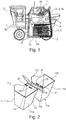
figure 1 represents in a side view a harvesting machine according to the invention, with a partial cross-section showing the recovery unit; -
figure 2 represents schematically in perspective the association of two adjacent buckets of a conveyor of the recovery unit offigure 1 with a system according to the invention; -
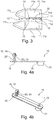
figure 3 represents schematically in a top view the buckets offigure 2 after their assembly; -
figures 4 represents schematically a tab of a system according to an embodiment of the invention, respectively in a side view (figure 4a ), in a perspective top view (figure 4b ) and in a perspective bottom view (figure 4c ); -
figure 5 represents schematically in perspective two tabs according tofigures 4 after their irreversible coupling; -
figure 6 represents in a side view a tab of a system according to another embodiment of the invention; -
figures 7 to 9 represent in perspective a tab of a system according to respective other embodiments of the invention. - In relation to those figures, we describe below a harvesting machine comprising a harvest recovery unit which comprises at least one conveyor comprising an elongated traction member and a row of buckets associated to one another by means of a least one system for associating two elements by their adjacent flexible walls.
- The harvesting machine is in particular arranged for the mechanical harvesting of fruits growing on plants, such as trees or bushes, that are arranged in rows, such as grapes, berries, coffee beans, olives etc., and in particular fruits growing in bunches.
- To do so, the harvesting machine comprises a
motorized support structure 1 that is equipped with a driver station 2 and that is movable along rows ofplants 3, a harvesting unit 4 being mounted on said structure for straddling at least one of said rows of plants and detaching fruits F from said plants. - In particular, the harvesting unit 4 can be mounted on the
support structure 1 permanently or removably, so as to be replaceable by other equipment and accessories, for example spraying equipment, pruning equipment or equipment for working the soil. - The harvesting unit 4 includes a straddling chassis which delimits a harvesting tunnel into which the
plants 3 are successively introduced to move through said tunnel between respective openings at the front and at the rear of said tunnel. Moreover, the harvesting unit 4 includes a shaker system including two shaker devices 5, said shaker devices being arranged on respective sides of the harvesting tunnel to delimit said tunnel transversely. - The harvesting machine also includes a recovery unit 6 for recovering the harvest detached by the harvesting unit 4 and a
unit 7 for cleaning and/or sorting said detached harvest to eliminate components L other than fruits F, in particular leaves, leaf stalks and wood particles, before the storage of said harvest in at least onehopper 8 provided for that purpose on the harvesting machine or in an ancillary trailer. - In relation to
figure 1 , the recovery unit 6 comprises two bucket conveyors 9 that are arranged on respective sides of the harvesting tunnel, said conveyors being adapted to recover the detached harvest underneath the harvesting unit 4 and to convey said harvest into the upper part of the harvesting machine, wherein a cleaning/sorting unit 7 and at least one storinghopper 8 are mounted. - In particular, each conveyor 9 forms a closed loop with a bottom run 9a arranged for recovering the detached harvest by gravity underneath the harvesting unit 4, a
top run 9b for feeding the cleaning/sorting unit 7 with said detached harvest, and substantially verticalintermediate runs 9c which extends respectively between the front and rear ends of said top and bottom runs. - Each conveyor 9 comprises an
elongated traction member 10, such as a chain or a belt, and a plurality ofbuckets 11 that are arranged in a row on said traction member for forming a continuous recovery belt on said traction member, eachbucket 11 comprising a flexible body made from a flexible polymeric material, in particular based on polyurethane, so as to ensure soft contact on theplants 3. - With reference to
figures 2 and3 , eachbucket 11 comprises abottom wall 11a which is secured to the traction member 10 (not shown), for example by means of bolts and nuts, a pair ofopposite walls 11b which are intended to extend transversely to the moving direction of thetraction member 10, and a pair ofopposite side walls bottom wall 11a. - Advantageously, as described in document
FR-2 399 793 support structure 1 so that theirrespective bottom runs 9a are adjacent to one another and guided on either side of a row ofplants 3 which moves across the harvesting tunnel, so as to clamp said plants of said row at the lower portion of the stem thereof, so that the fruits F detached from said plants would fall directly by gravity into the bottom runs 9a. - Moreover, the
respective buckets 11 of the conveyors 9 are arranged to form recovery belts that are arranged to imbricate into one another in at least the zone of the bottom runs 9a, so as to ensure a sealing between said conveyors at said imbrication zone. To do so, therespective buckets 11 of each conveyor 9 comprise a beak-shaped side wall 11c which is arranged facing the interior of the harvesting tunnel. - In particular, each beak-
shaped side wall 11c of a conveyor 9 is intended to closely engage within acomplementary space 12 formed between two adjacent beak-shaped side walls 11c of another conveyor at the zone of the bottom runs 9a for preventing any clearance between conveyors 9 at said bottom runs, and then to prevent the risk of harvest products F dropping through such clearances. - In the same way, each
bucket 11 of a conveyor 9 is associated at itstransverse walls 11b to flexibletransverse walls 11c ofadjacent buckets 11 in the row, so as to ensure a maximum sealing of the recovery belt of said conveyor for receiving all the detached harvest F without ground losses. - To that end, in relation to
figures 2 and3 , the invention provides for associating to one anotheradjacent buckets 11 of a conveyor 9 by means of at least a system comprising: - the two adjacent
transverse walls 11b of said buckets and at least twoorifices 14 formed in each of said walls to be aligned two by two when said walls are in a juxtaposed position; - a pair of
tabs 15 being operable to be arranged next to the alignedorifices 14 respectively on one side of juxtaposedwalls 11b; - mutual coupling means for coupling said tabs, said mutual coupling means being adapted to be engaged through said aligned orifices in a position wherein said walls are plated between said tabs.
- The coupling means comprise a
pin 16 provided on onetab 15 and ahole 17 provided on theother tab 15, thepin 16 and thehole 17 being operable to be disposed respectively through and next to the alignedorifices 14 when said tabs are arranged on either side of the juxtaposedwalls 11b, apin 16 of atab 15 being arranged to be irreversibly coupled within ahole 17 of anothertab 15 in a position wherein said walls are plated between said tabs. - Thus, the system allows for associating
adjacent buckets 11 in a simple and relatively intuitive manner, especially without the use of specific, complex and cumbersome tools, and that in relative quick manner, in particular a few seconds. - Indeed, such a system only requires for a human operator to manually juxtapose to one another the adjacent
transverse walls 11b to be associated, in particular by aligning together respective pairs ofassociation orifices 14 of said walls, then to manually arrange the twotabs 15 of the system by disposing thepins 16 orholes 17 of eachtab 15 in and next to respectively two alignedorifices 14, and then to couple said tabs, either with a simple tool such as a standard pair of flat pliers or even manually, by irreversibly engaging said pins within said holes by a simple pinching gesture. - In particular, each
tab 15 may be made in one piece in polymeric material, in particular from polyamide, which allows not only to simplify their manufacturing and to reduce their costs, but also to comply with alimentary regulation, as said tabs may be in contact with fruits F to be harvested. To that end, thetabs 15 may be for example made from thepolyamide 11, which is particularly appropriate as it is made with natural components. - Moreover, the
tabs 15 both present a substantially rectangular geometry, a first 16, 17 and a second 16, 17 coupling means being formed at respective ends thereof. - According to an embodiment, represented on
figures 4 to 7 and9 , eachtab 15 comprises at least apin 16 and at least ahole 17, thepins 16 of eachtab 15 being arranged to be irreversibly coupled within ahole 17 of eachother tab 15 in a position wherein thewalls 11b are plated between said tabs disposed head to tail. - Advantageously, the system may comprise a pair of
identical tabs 15 that are both made from a same mould, which allows to reduce even more their manufacturing costs and the operation of their coupling two by two. - According to another embodiment, represented on
figures 8 , the system comprises atab 15 which presents coupling means that are all formed by a pin 16 (figure 8a ), whereas theother tab 15 presents coupling means that are all formed by a hole 17 (figure 8b ). - As represented on
figures 2 and3 , the adjacenttransverse walls 11b are associated to one another by two transversally spaced systems, which allows to improve said association, and then to improve the sealing of the recovery belt at said association. - According to a variant not represented, the adjacent
transverse walls 11b can be associated to one another by only one system, especially in the case when thebuckets 11, and thus thetransverse walls 11b thereof, present reduced dimensions. - In particular, for associating such
small buckets 11, thetabs 15 may comprise a length extension 15' which is provided with a third coupling means 16, 17, as indicated in dotted lines onfigures 8 and9 . - Moreover, in relation to
figure 6 , the system can advantageously comprisetabs 15 that are elastically deformable between a free longitudinally-curved state and a constrained longitudinally-straight state, said tabs being intended to be arranged on either side of juxtaposedadjacent walls 11b with the apex of said curvatures bearing on said walls, the coupling means 16, 17 being arranged to constraint thetabs 15 in their longitudinally-straight state, in order to be able to compress thewalls 11b between the coupledtabs 15. - Thus, the
walls 11b can benefit from a more tightly association, which allows to prevent infiltration of polluting and sticky substances, such as dust particles and fruit juices, between said walls, and then to facilitate the cleaning of the conveyor 9 after the harvest and to prevent the risks of pollution for the next harvests. - Moreover, the
tabs 15 comprises each at least one stiffening rib, notably tworadial stiffening ribs 18a that extend next to respectively thepin 16 and thehole 17 thereof and/or alongitudinal stiffening rib 18b that extends between said pin and said hole. - With reference to
figures 4 to 9 , eachpin 16 comprises ahead 19 linked to thetab 15 by astem 20, said head being arranged to be snap fitted in ahole 17 to accomplish the association of thewalls 11b. Moreover, eachhole 17 is surrounded by ahollow sleeve 21 which is intended to form a housing for receiving thehead 19 of thepin 16 coupled within said hole. - In particular, each
head 19 comprises a flexible structure, in particular in the shape of an umbrella, which is elastically deformable between a free deployed and a constrained retracted state, eachhole 17 comprising a collar 22 whereon the structure of anotherhead 19 is at first retractable for allowing said head to pass through, and then is retained in the free deployed state upon said passage to ensure the snap fitting. - Thus, thanks to the snap fit coupling of the
tabs 15, theadjacent walls 11b are associated to one another in a simple and secure manner, which allows to ensure the sealing of the recovery belt with a good reliability. - However, such association must not be too strong, because it may trigger tearing damages on
buckets 11 if one of said buckets is hung on a fixed element, such as a pole or an iron wire, during the harvesting. Moreover, if the coupling means 16, 17 are too strong, theassociation tabs 15 may also irreversibly deform during a tearing off of thebuckets 11 from one another, which may also cause damages to the conveyor 9 and/or to the harvesting machine, due to potential hits betweendeformed tabs 15 and other structures of said conveyor and/or said machine. - To avoid such drawbacks, the system may be arranged as a fuse, in particular to be breakable upon a threshold stress applied between the coupled
tabs 15 thereof, so as to limit the damage risks onflexible walls 11b in case of a tearing off from one another. - To do so, the stems 20 of each
pin 16 comprise a weakened zone 23 which is arranged to be breakable upon the occurrence of such a threshold stress, in particular a stress with an intensity comprised between 25 and 30 kg. In particular, as represented onfigures 4 and6 , the stems 20 comprise an area 24 of reduced section which is formed at the proximity of thehead 19, said reduced section area forming the weakened zone 23. - Thus, in the case of a tearing off of two
buckets 11 from one another, the system, instead of resisting to the applied stress, will simply break at the weakened zones 23, which may cause a separation of the associatedwalls 11b without causing any tearing damage on them. As a matter of fact, the impact on the sealing of the recovery belt will be small, asadjacent buckets 11 are still connected to thetraction member 10, and the maintenance operations to be performed after the harvest will only require a simple replacement of the broken association system(s), instead of complex, expensive and fastidious dismounting(s) of tornbuckets 11. - In particular, to facilitate the replacement of broken systems, and thus to save time during the maintenance operations, the
tabs 15 may display a showy contrast of colour, for example by being dark blue or black whereas thebuckets 11 are more pale or white, so that a human operator may quickly and easily detect a broken or even absent system for replacing it.
Claims (20)
- System for associating two elements (11) by their adjacent flexible walls (11b), said system comprising:- said two walls and at least two orifices (14) formed in each of said walls to be aligned two by two when said walls are in a juxtaposed position;- a pair of tabs (15) being operable to be arranged next to the aligned orifices (14) respectively on one side of juxtaposed walls (11b);- mutual coupling means (16, 17) for coupling said tabs, said mutual coupling means being adapted to be engaged through said aligned orifices in a position wherein said walls are plated between said tabs;said system being characterized in that said mutual coupling means comprise a pin (16) provided on one tab (15) and a hole (17) provided on the other tab (15), the pin (16) and the hole (17) being operable to be disposed respectively through and next to the aligned orifices (14) when said tabs are arranged on either side of the juxtaposed walls (11b), a pin (16) of a tab (15) being arranged to be irreversibly coupled within a hole (17) of another tab (15) in a position wherein said walls are plated between said tabs.
- System according to claim 1, characterized in that each pin (16) comprises a head (19) linked to the tab (15) by a stem (20), said head being arranged to be snap fitted in a hole (17) to accomplish the association of the walls (11b).
- System according to claim 2, characterized in that the head (19) comprises a flexible structure which is elastically deformable between a free deployed and a constrained retracted state, the hole (17) comprising a collar (22) whereon the structure is retractable for allowing said head to pass through and is retained in the free deployed state upon said passage to ensure the snap fitting.
- System according to claims 2 or 3, characterized in that the stem (20) comprises a weakened zone (23) which is breakable by a threshold stress applied between the coupled tabs (15).
- System according to claim 4, characterized in that the stem (20) comprises an area (24) of reduced section which is formed at the proximity of the head (19), said reduced section area forming the weakened zone (23).
- System according to any of claims 1 to 5, characterized in that the hole (17) is surrounded by a hollow sleeve (21), said sleeve forming a housing for receiving the pin (16) coupled within said hole.
- System according to any of claims 1 to 6, characterized in that it comprises a pair of identical tabs (15).
- System according to any of claims 1 to 7, characterized in that each tab (15) comprises at least a pin (16) and at least a hole (17), the pins (16) of each tab (15) being arranged to be irreversibly coupled within a hole (17) of each other tab (15) in a position wherein the walls (11b) are plated between said tabs disposed head to tail.
- System according to any of claims 1 to 6, characterized in that a tab (15) presents couplings means that are all formed by a pin (16), the other tab (15) presenting couplings means that are all formed by a hole (17).
- System according to any of claims 1 to 9, characterized in that the tabs (15) present a substantially rectangular geometry, a first (16, 17) and a second (16, 17) coupling means being formed at respectively an end thereof.
- System according to any of claims 1 to 10, characterized in that the tabs (15) are elastically deformable between a free longitudinally-curved state and a constrained longitudinally-straight state, said tabs being intended to be arranged on either side of juxtaposed adjacent walls (11b) with the apex of said curvatures bearing on said walls, the coupling means (16, 17) being arranged to constraint the tabs (15) in their longitudinally-straight state thereby compressing the walls (11b) between the coupled tabs (15).
- System according to any of claims 1 to 11, characterized in that the tabs (15) comprise at least one stiffening rib (18a, 18b).
- System according to any of claims 1 to 12, characterized in that the tabs (15) are made in one piece in polymeric material.
- System according to claim 13, characterized in that the tabs (15) are made from polyamide, in particular polyamide 11.
- Conveyor (9) comprising an elongated traction member (10) and a plurality of buckets (11) that are arranged in a row on said traction member for forming a recovery belt on said traction member, each bucket (11) comprising a flexible body with a pair of opposite walls (11b) extending transversely to the moving direction of the traction member (10), said conveyor being characterized in that the buckets (11) are associated to one another by means of at least one system according to any of claims 1 to 14.
- Conveyor (9) according to claim 15, characterized in that the adjacent transverse walls (11b) are associated by two transversally spaced systems.
- Conveyor (9) according to claim 15 or 16, characterized in that each bucket (11) is made from a flexible polymeric material, in particular based on polyurethane.
- Harvesting machine comprising a motorised support structure (1) which is movable along rows of plants (3), said structure comprising a harvesting unit (4) for detaching fruits (F) from said plants and a recovery unit (6) for recovering the detached harvest (F), said recovery unit comprising at least one conveyor (9) according to any of claims 15 to 17.
- Harvesting machine according to claim 18, characterized in that it comprises two conveyors (9) the respective buckets (11) thereof forming recovery belts that are arranged to imbricate into one another on at least a zone (9a).
- A tab (15) of the pair of tabs (15) of the system according to any of the claims 1 to 14.
Applications Claiming Priority (2)
| Application Number | Priority Date | Filing Date | Title |
|---|---|---|---|
| EP16305981.9A EP3275811A1 (en) | 2016-07-28 | 2016-07-28 | System for associating two elements by their adjacent flexible walls |
| PCT/EP2017/068946 WO2018019916A1 (en) | 2016-07-28 | 2017-07-27 | System for associating two elements by their adjacent flexible walls |
Publications (2)
| Publication Number | Publication Date |
|---|---|
| EP3490912A1 EP3490912A1 (en) | 2019-06-05 |
| EP3490912B1 true EP3490912B1 (en) | 2020-06-24 |
Family
ID=56567550
Family Applications (2)
| Application Number | Title | Priority Date | Filing Date |
|---|---|---|---|
| EP16305981.9A Withdrawn EP3275811A1 (en) | 2016-07-28 | 2016-07-28 | System for associating two elements by their adjacent flexible walls |
| EP17742451.2A Active EP3490912B1 (en) | 2016-07-28 | 2017-07-27 | System for associating two elements by their adjacent flexible walls |
Family Applications Before (1)
| Application Number | Title | Priority Date | Filing Date |
|---|---|---|---|
| EP16305981.9A Withdrawn EP3275811A1 (en) | 2016-07-28 | 2016-07-28 | System for associating two elements by their adjacent flexible walls |
Country Status (5)
| Country | Link |
|---|---|
| US (1) | US11191214B2 (en) |
| EP (2) | EP3275811A1 (en) |
| BR (1) | BR112019001547B1 (en) |
| ES (1) | ES2807190T3 (en) |
| WO (1) | WO2018019916A1 (en) |
Family Cites Families (12)
| Publication number | Priority date | Publication date | Assignee | Title |
|---|---|---|---|---|
| US3050578A (en) * | 1958-08-07 | 1962-08-21 | Gen Motors Corp | Retainer |
| DE1756905C3 (en) | 1968-07-31 | 1974-06-12 | Westland Gummiwerke Gmbh & Co, 4521 Westerhausen | Conveyor belt with rectangular cups of U-shaped cross-section made of elastic material |
| US3795305A (en) * | 1973-01-22 | 1974-03-05 | Universal Ind | Bucket conveyor system |
| FR2399793A1 (en) * | 1977-08-12 | 1979-03-09 | Braud Sa | HARVESTING MACHINE FOR INLINE CROPS, ESPECIALLY FOR VINES |
| US4175880A (en) * | 1977-09-16 | 1979-11-27 | Postalia Gmbh | Device for interlocking perforated writing material |
| AUPO277096A0 (en) * | 1996-10-04 | 1996-10-31 | Jarmain, Paul Laurence | Bucket elevator improvements |
| JP4260910B2 (en) * | 1997-12-02 | 2009-04-30 | 株式会社コーテックス | Sealing tool |
| US6287064B1 (en) * | 1999-12-10 | 2001-09-11 | Western Sky Industries, Inc. | Clip type fastener assembly |
| FR2813493A1 (en) * | 2000-09-05 | 2002-03-08 | New Holland Braud Sa | HARVESTING DEVICE WITH DETACHABLE SHAKERS FOR FRUIT, BERRY AND THE LIKE HARVESTING MACHINE |
| US8316514B2 (en) * | 2007-09-21 | 2012-11-27 | Newfry Llc | Trim clip for trim for curtain side air bag |
| FR2932856B1 (en) * | 2008-06-18 | 2010-08-13 | Caillau Ets | TIGHTENING COLLAR WITH EMBOUTIZED COUPLING PIN |
| US8205742B2 (en) * | 2008-08-01 | 2012-06-26 | Oxbo International Corporation | Harvester bucket |
-
2016
- 2016-07-28 EP EP16305981.9A patent/EP3275811A1/en not_active Withdrawn
-
2017
- 2017-07-27 US US16/321,461 patent/US11191214B2/en active Active
- 2017-07-27 WO PCT/EP2017/068946 patent/WO2018019916A1/en not_active Ceased
- 2017-07-27 EP EP17742451.2A patent/EP3490912B1/en active Active
- 2017-07-27 BR BR112019001547-7A patent/BR112019001547B1/en active IP Right Grant
- 2017-07-27 ES ES17742451T patent/ES2807190T3/en active Active
Non-Patent Citations (1)
| Title |
|---|
| None * |
Also Published As
| Publication number | Publication date |
|---|---|
| US11191214B2 (en) | 2021-12-07 |
| EP3490912A1 (en) | 2019-06-05 |
| ES2807190T3 (en) | 2021-02-22 |
| EP3275811A1 (en) | 2018-01-31 |
| US20190174676A1 (en) | 2019-06-13 |
| WO2018019916A1 (en) | 2018-02-01 |
| BR112019001547B1 (en) | 2022-11-01 |
| BR112019001547A2 (en) | 2019-05-14 |
| ES2807190T8 (en) | 2021-03-02 |
Similar Documents
| Publication | Publication Date | Title |
|---|---|---|
| US8117814B2 (en) | Crop catching apparatus and crop harvesting machine employing the same | |
| US20150173298A1 (en) | Sugarcane Harvesting Machine | |
| PL139112B1 (en) | Apparatus for harvesting corn or other grain crops | |
| JP7127773B2 (en) | crop harvester | |
| US11191214B2 (en) | System for associating two elements by their adjacent flexible walls | |
| US5976013A (en) | Device for preventing accumulation of grain in combine harvester | |
| JP2014233225A (en) | Harvesting machine | |
| EP3087016B1 (en) | A conveyor belt with articulated links | |
| US20080000212A1 (en) | Pick up element for agricultural products having a thin and long-limbed shape such as grass, straw, leguminous and similar products, and a pick up device exploiting the same | |
| US4204389A (en) | Machine for harvesting in-line crops | |
| CN206371100U (en) | Harvesting device for corn harvester | |
| US20050091954A1 (en) | Harvester | |
| JP6208960B2 (en) | Tomato harvester | |
| EP3547819B1 (en) | Harvesting machine comprising a harvesting unit and a system for recovering the crop detached by said harvesting unit | |
| JP5793888B2 (en) | Crop harvester | |
| US9789798B2 (en) | Stick removal mechanism for nut harvesting | |
| JP2015000026A (en) | Corn harvesting machine | |
| JP2014233227A (en) | Corn harvesting machine | |
| US2462128A (en) | Beet harvesting means | |
| CN203985069U (en) | Corn harvester | |
| DE8600471U1 (en) | Harvester for row crops, especially sunflowers | |
| JP5531672B2 (en) | Root crop harvesting machine | |
| JP2015000027A (en) | Corn harvesting machine | |
| US20180020613A1 (en) | Belted chain connection system | |
| JP2001320930A (en) | Root vegetable harvester |
Legal Events
| Date | Code | Title | Description |
|---|---|---|---|
| STAA | Information on the status of an ep patent application or granted ep patent |
Free format text: STATUS: UNKNOWN |
|
| STAA | Information on the status of an ep patent application or granted ep patent |
Free format text: STATUS: THE INTERNATIONAL PUBLICATION HAS BEEN MADE |
|
| PUAI | Public reference made under article 153(3) epc to a published international application that has entered the european phase |
Free format text: ORIGINAL CODE: 0009012 |
|
| STAA | Information on the status of an ep patent application or granted ep patent |
Free format text: STATUS: REQUEST FOR EXAMINATION WAS MADE |
|
| 17P | Request for examination filed |
Effective date: 20190228 |
|
| AK | Designated contracting states |
Kind code of ref document: A1 Designated state(s): AL AT BE BG CH CY CZ DE DK EE ES FI FR GB GR HR HU IE IS IT LI LT LU LV MC MK MT NL NO PL PT RO RS SE SI SK SM TR |
|
| AX | Request for extension of the european patent |
Extension state: BA ME |
|
| DAV | Request for validation of the european patent (deleted) | ||
| DAX | Request for extension of the european patent (deleted) | ||
| GRAP | Despatch of communication of intention to grant a patent |
Free format text: ORIGINAL CODE: EPIDOSNIGR1 |
|
| STAA | Information on the status of an ep patent application or granted ep patent |
Free format text: STATUS: GRANT OF PATENT IS INTENDED |
|
| INTG | Intention to grant announced |
Effective date: 20200108 |
|
| GRAS | Grant fee paid |
Free format text: ORIGINAL CODE: EPIDOSNIGR3 |
|
| GRAA | (expected) grant |
Free format text: ORIGINAL CODE: 0009210 |
|
| STAA | Information on the status of an ep patent application or granted ep patent |
Free format text: STATUS: THE PATENT HAS BEEN GRANTED |
|
| AK | Designated contracting states |
Kind code of ref document: B1 Designated state(s): AL AT BE BG CH CY CZ DE DK EE ES FI FR GB GR HR HU IE IS IT LI LT LU LV MC MK MT NL NO PL PT RO RS SE SI SK SM TR |
|
| REG | Reference to a national code |
Ref country code: GB Ref legal event code: FG4D |
|
| REG | Reference to a national code |
Ref country code: CH Ref legal event code: EP |
|
| REG | Reference to a national code |
Ref country code: AT Ref legal event code: REF Ref document number: 1283698 Country of ref document: AT Kind code of ref document: T Effective date: 20200715 |
|
| REG | Reference to a national code |
Ref country code: DE Ref legal event code: R096 Ref document number: 602017018726 Country of ref document: DE |
|
| REG | Reference to a national code |
Ref country code: IE Ref legal event code: FG4D |
|
| PG25 | Lapsed in a contracting state [announced via postgrant information from national office to epo] |
Ref country code: SE Free format text: LAPSE BECAUSE OF FAILURE TO SUBMIT A TRANSLATION OF THE DESCRIPTION OR TO PAY THE FEE WITHIN THE PRESCRIBED TIME-LIMIT Effective date: 20200624 Ref country code: GR Free format text: LAPSE BECAUSE OF FAILURE TO SUBMIT A TRANSLATION OF THE DESCRIPTION OR TO PAY THE FEE WITHIN THE PRESCRIBED TIME-LIMIT Effective date: 20200925 Ref country code: LT Free format text: LAPSE BECAUSE OF FAILURE TO SUBMIT A TRANSLATION OF THE DESCRIPTION OR TO PAY THE FEE WITHIN THE PRESCRIBED TIME-LIMIT Effective date: 20200624 Ref country code: NO Free format text: LAPSE BECAUSE OF FAILURE TO SUBMIT A TRANSLATION OF THE DESCRIPTION OR TO PAY THE FEE WITHIN THE PRESCRIBED TIME-LIMIT Effective date: 20200924 Ref country code: FI Free format text: LAPSE BECAUSE OF FAILURE TO SUBMIT A TRANSLATION OF THE DESCRIPTION OR TO PAY THE FEE WITHIN THE PRESCRIBED TIME-LIMIT Effective date: 20200624 |
|
| REG | Reference to a national code |
Ref country code: LT Ref legal event code: MG4D |
|
| PG25 | Lapsed in a contracting state [announced via postgrant information from national office to epo] |
Ref country code: LV Free format text: LAPSE BECAUSE OF FAILURE TO SUBMIT A TRANSLATION OF THE DESCRIPTION OR TO PAY THE FEE WITHIN THE PRESCRIBED TIME-LIMIT Effective date: 20200624 Ref country code: HR Free format text: LAPSE BECAUSE OF FAILURE TO SUBMIT A TRANSLATION OF THE DESCRIPTION OR TO PAY THE FEE WITHIN THE PRESCRIBED TIME-LIMIT Effective date: 20200624 Ref country code: RS Free format text: LAPSE BECAUSE OF FAILURE TO SUBMIT A TRANSLATION OF THE DESCRIPTION OR TO PAY THE FEE WITHIN THE PRESCRIBED TIME-LIMIT Effective date: 20200624 Ref country code: BG Free format text: LAPSE BECAUSE OF FAILURE TO SUBMIT A TRANSLATION OF THE DESCRIPTION OR TO PAY THE FEE WITHIN THE PRESCRIBED TIME-LIMIT Effective date: 20200924 |
|
| REG | Reference to a national code |
Ref country code: NL Ref legal event code: MP Effective date: 20200624 |
|
| REG | Reference to a national code |
Ref country code: AT Ref legal event code: MK05 Ref document number: 1283698 Country of ref document: AT Kind code of ref document: T Effective date: 20200624 |
|
| PG25 | Lapsed in a contracting state [announced via postgrant information from national office to epo] |
Ref country code: AL Free format text: LAPSE BECAUSE OF FAILURE TO SUBMIT A TRANSLATION OF THE DESCRIPTION OR TO PAY THE FEE WITHIN THE PRESCRIBED TIME-LIMIT Effective date: 20200624 Ref country code: NL Free format text: LAPSE BECAUSE OF FAILURE TO SUBMIT A TRANSLATION OF THE DESCRIPTION OR TO PAY THE FEE WITHIN THE PRESCRIBED TIME-LIMIT Effective date: 20200624 |
|
| PG25 | Lapsed in a contracting state [announced via postgrant information from national office to epo] |
Ref country code: CZ Free format text: LAPSE BECAUSE OF FAILURE TO SUBMIT A TRANSLATION OF THE DESCRIPTION OR TO PAY THE FEE WITHIN THE PRESCRIBED TIME-LIMIT Effective date: 20200624 Ref country code: RO Free format text: LAPSE BECAUSE OF FAILURE TO SUBMIT A TRANSLATION OF THE DESCRIPTION OR TO PAY THE FEE WITHIN THE PRESCRIBED TIME-LIMIT Effective date: 20200624 Ref country code: PT Free format text: LAPSE BECAUSE OF FAILURE TO SUBMIT A TRANSLATION OF THE DESCRIPTION OR TO PAY THE FEE WITHIN THE PRESCRIBED TIME-LIMIT Effective date: 20201026 Ref country code: AT Free format text: LAPSE BECAUSE OF FAILURE TO SUBMIT A TRANSLATION OF THE DESCRIPTION OR TO PAY THE FEE WITHIN THE PRESCRIBED TIME-LIMIT Effective date: 20200624 Ref country code: SM Free format text: LAPSE BECAUSE OF FAILURE TO SUBMIT A TRANSLATION OF THE DESCRIPTION OR TO PAY THE FEE WITHIN THE PRESCRIBED TIME-LIMIT Effective date: 20200624 Ref country code: EE Free format text: LAPSE BECAUSE OF FAILURE TO SUBMIT A TRANSLATION OF THE DESCRIPTION OR TO PAY THE FEE WITHIN THE PRESCRIBED TIME-LIMIT Effective date: 20200624 |
|
| REG | Reference to a national code |
Ref country code: ES Ref legal event code: FG2A Ref document number: 2807190 Country of ref document: ES Kind code of ref document: T3 Effective date: 20210222 |
|
| PG25 | Lapsed in a contracting state [announced via postgrant information from national office to epo] |
Ref country code: SK Free format text: LAPSE BECAUSE OF FAILURE TO SUBMIT A TRANSLATION OF THE DESCRIPTION OR TO PAY THE FEE WITHIN THE PRESCRIBED TIME-LIMIT Effective date: 20200624 Ref country code: PL Free format text: LAPSE BECAUSE OF FAILURE TO SUBMIT A TRANSLATION OF THE DESCRIPTION OR TO PAY THE FEE WITHIN THE PRESCRIBED TIME-LIMIT Effective date: 20200624 Ref country code: IS Free format text: LAPSE BECAUSE OF FAILURE TO SUBMIT A TRANSLATION OF THE DESCRIPTION OR TO PAY THE FEE WITHIN THE PRESCRIBED TIME-LIMIT Effective date: 20201024 |
|
| REG | Reference to a national code |
Ref country code: CH Ref legal event code: PL |
|
| REG | Reference to a national code |
Ref country code: DE Ref legal event code: R097 Ref document number: 602017018726 Country of ref document: DE |
|
| PG25 | Lapsed in a contracting state [announced via postgrant information from national office to epo] |
Ref country code: MC Free format text: LAPSE BECAUSE OF FAILURE TO SUBMIT A TRANSLATION OF THE DESCRIPTION OR TO PAY THE FEE WITHIN THE PRESCRIBED TIME-LIMIT Effective date: 20200624 |
|
| REG | Reference to a national code |
Ref country code: BE Ref legal event code: MM Effective date: 20200731 |
|
| PG25 | Lapsed in a contracting state [announced via postgrant information from national office to epo] |
Ref country code: DK Free format text: LAPSE BECAUSE OF FAILURE TO SUBMIT A TRANSLATION OF THE DESCRIPTION OR TO PAY THE FEE WITHIN THE PRESCRIBED TIME-LIMIT Effective date: 20200624 Ref country code: CH Free format text: LAPSE BECAUSE OF NON-PAYMENT OF DUE FEES Effective date: 20200731 Ref country code: LU Free format text: LAPSE BECAUSE OF NON-PAYMENT OF DUE FEES Effective date: 20200727 Ref country code: LI Free format text: LAPSE BECAUSE OF NON-PAYMENT OF DUE FEES Effective date: 20200731 |
|
| PLBE | No opposition filed within time limit |
Free format text: ORIGINAL CODE: 0009261 |
|
| STAA | Information on the status of an ep patent application or granted ep patent |
Free format text: STATUS: NO OPPOSITION FILED WITHIN TIME LIMIT |
|
| PG25 | Lapsed in a contracting state [announced via postgrant information from national office to epo] |
Ref country code: BE Free format text: LAPSE BECAUSE OF NON-PAYMENT OF DUE FEES Effective date: 20200731 |
|
| 26N | No opposition filed |
Effective date: 20210325 |
|
| PG25 | Lapsed in a contracting state [announced via postgrant information from national office to epo] |
Ref country code: SI Free format text: LAPSE BECAUSE OF FAILURE TO SUBMIT A TRANSLATION OF THE DESCRIPTION OR TO PAY THE FEE WITHIN THE PRESCRIBED TIME-LIMIT Effective date: 20200624 Ref country code: IE Free format text: LAPSE BECAUSE OF NON-PAYMENT OF DUE FEES Effective date: 20200727 |
|
| GBPC | Gb: european patent ceased through non-payment of renewal fee |
Effective date: 20210727 |
|
| PG25 | Lapsed in a contracting state [announced via postgrant information from national office to epo] |
Ref country code: GB Free format text: LAPSE BECAUSE OF NON-PAYMENT OF DUE FEES Effective date: 20210727 |
|
| PG25 | Lapsed in a contracting state [announced via postgrant information from national office to epo] |
Ref country code: TR Free format text: LAPSE BECAUSE OF FAILURE TO SUBMIT A TRANSLATION OF THE DESCRIPTION OR TO PAY THE FEE WITHIN THE PRESCRIBED TIME-LIMIT Effective date: 20200624 Ref country code: MT Free format text: LAPSE BECAUSE OF FAILURE TO SUBMIT A TRANSLATION OF THE DESCRIPTION OR TO PAY THE FEE WITHIN THE PRESCRIBED TIME-LIMIT Effective date: 20200624 Ref country code: CY Free format text: LAPSE BECAUSE OF FAILURE TO SUBMIT A TRANSLATION OF THE DESCRIPTION OR TO PAY THE FEE WITHIN THE PRESCRIBED TIME-LIMIT Effective date: 20200624 |
|
| PG25 | Lapsed in a contracting state [announced via postgrant information from national office to epo] |
Ref country code: MK Free format text: LAPSE BECAUSE OF FAILURE TO SUBMIT A TRANSLATION OF THE DESCRIPTION OR TO PAY THE FEE WITHIN THE PRESCRIBED TIME-LIMIT Effective date: 20200624 |
|
| PGFP | Annual fee paid to national office [announced via postgrant information from national office to epo] |
Ref country code: ES Payment date: 20250812 Year of fee payment: 9 |
|
| PGFP | Annual fee paid to national office [announced via postgrant information from national office to epo] |
Ref country code: DE Payment date: 20250728 Year of fee payment: 9 |
|
| PGFP | Annual fee paid to national office [announced via postgrant information from national office to epo] |
Ref country code: IT Payment date: 20250721 Year of fee payment: 9 |
|
| PGFP | Annual fee paid to national office [announced via postgrant information from national office to epo] |
Ref country code: FR Payment date: 20250725 Year of fee payment: 9 |