EP3490822B1 - A trailer hitch guide adaptor - Google Patents
A trailer hitch guide adaptor Download PDFInfo
- Publication number
- EP3490822B1 EP3490822B1 EP17730468.0A EP17730468A EP3490822B1 EP 3490822 B1 EP3490822 B1 EP 3490822B1 EP 17730468 A EP17730468 A EP 17730468A EP 3490822 B1 EP3490822 B1 EP 3490822B1
- Authority
- EP
- European Patent Office
- Prior art keywords
- guide
- plate
- mounting plate
- trailer
- adaptor
- Prior art date
- Legal status (The legal status is an assumption and is not a legal conclusion. Google has not performed a legal analysis and makes no representation as to the accuracy of the status listed.)
- Active
Links
Images



Classifications
-
- B—PERFORMING OPERATIONS; TRANSPORTING
- B60—VEHICLES IN GENERAL
- B60D—VEHICLE CONNECTIONS
- B60D1/00—Traction couplings; Hitches; Draw-gear; Towing devices
- B60D1/24—Traction couplings; Hitches; Draw-gear; Towing devices characterised by arrangements for particular functions
- B60D1/36—Traction couplings; Hitches; Draw-gear; Towing devices characterised by arrangements for particular functions for facilitating connection, e.g. hitch catchers
- B60D1/363—Hitch guiding or catching elements, e.g. V-shaped plates partially surrounding a coupling member for guiding the other coupling member
-
- B—PERFORMING OPERATIONS; TRANSPORTING
- B60—VEHICLES IN GENERAL
- B60D—VEHICLE CONNECTIONS
- B60D1/00—Traction couplings; Hitches; Draw-gear; Towing devices
- B60D1/01—Traction couplings or hitches characterised by their type
- B60D1/06—Ball-and-socket hitches
-
- B—PERFORMING OPERATIONS; TRANSPORTING
- B60—VEHICLES IN GENERAL
- B60D—VEHICLE CONNECTIONS
- B60D1/00—Traction couplings; Hitches; Draw-gear; Towing devices
- B60D1/48—Traction couplings; Hitches; Draw-gear; Towing devices characterised by the mounting
Definitions
- the present disclosure relates to a trailer hitch guide adaptor, more specifically to be mounted on a trailer tongue coupler, i.e. on part of a trailer.
- the disclosure further relates to a trailer tongue coupler attached with the trailer hitch guide adaptor.
- Trailer tongue couplers on trailers typically have a hole adapted to receive a hitch ball, typically placed on a towing vehicle, or a car, such that the hitch ball is able to connect with a lock inside the trailer tongue coupler, thereby connecting the towing vehicle to the trailer.
- Connecting the hitch ball to the hole on the trailer tongue coupler requires a lot a driving in reverse. The driver needs to carefully drive the car towards the trailer, more specifically towards the trailer tongue. Depending on the reverse driving skills of the driver, the hitch ball is typically placed within a meter of the hole of the trailer tongue.
- the driver might be able to step out of the car and grab the trailer tongue, such that the driver pulls and/or pushes the trailer by the trailer tongue the last meter and might be able to place the hole above the hitch ball, release the trailer tongue, and thereby connect the trailer to the car.
- the described manoeuvre might be possible if the driver is strong and/or the trailer is light weight. Nevertheless, the manoeuvres might not be desirable and even dangerous. Furthermore, for heavy trailers, and regardless of how strong the driver is, the described manoeuvre might be impossible.
- a problem is that it is not easy and/or impossible to connect a trailer to a car.
- One solution to this problem is to provide a trailer tongue coupler with two guide plates, such that the hitch ball is guided towards the hole of the trailer tongue coupler.
- using the trailer tongue couplers with two guide plates is problematic because their construction is weak, and might easily break, especially when a heavy car bumps into the guide plates.
- getting the trailer tongue couplers with two guide plates is typically an expensive solution.
- a trailer hitch guide adaptor according to the preamble of claim 1 is known from US 6 179 318 B1 .
- the present disclosure relates in a first aspect to a trailer hitch guide adaptor for a trailer tongue coupler, comprising: a mounting plate configured for attachment to the trailer tongue coupler, the mounting plate having an mounting plate upper-surface and a mounting plate front-end; a pair of guide plates, each of the guide plates attached below the mounting plate, each of the guide plates having a guide plate front-end and a guide plate back-end, wherein said guide plates are angled relative to each other, whereby each of the guide plate back-ends converge towards each other and towards a converging line; and a third guide plate extending outwards from the mounting plate front-end, the third guide plate having a third guide plate upper surface, wherein the third guide plate upper surface defines an obtuse angle relative to the mounting plate upper surface, such that a hitch ball is able to be guided towards the mounting plate front-end via the third guide plate, and/or from below the mounting plate and towards the guide plate back ends via one of the guide plates attached below the mounting plate.
- the present trailer hitch guide adaptor is first of all provided means for providing a low cost trailer tongue coupler, in that the just presented trailer hitch guide adaptor is able to convert a low cost trailer tongue coupler to a trailer hitch guide, simply by mounting the trailer hitch guide adaptor to an existing trailer tongue coupler. Furthermore, by the present trailer hitch guide adaptor, when mounted to a trailer tongue coupler, is also provided a solidly constructed trailer tongue coupler that is able to guide a hitch ball into a position, where the hitch ball is able to connect to the trailer tongue coupler. In particular because there is a third guide plate extending outwards from the mounting plate front-end, there is facilitated a solid construction. The third guide plate serves per se as an extra guidance of the hitch ball.
- the third guide plate has a connection from the mounting plate, i.e. from a line on the mounting plate front-end, which facilitates that force from a hitch ball is transferred to the mounting plate via several points on that line.
- the mounting plate front-end defined a width of more than 5 cm, such as more than 10 cm, or such as more than 15 cm.
- a third guide plate is known from designs of hitch guides located on cars, neither on an adaptor for a trailer tongue coupler nor on a trailer tongue coupler.
- the third guide plate typically extend from a converging point, thus not a line as in the present invention.
- hitch guides with a third guide plate located on cars have been constructions rather weakly.
- the present invention provides for a very robust construction.
- the third guide plate also serves to protect the trailer tongue coupler from the hitch ball during connection.
- a hitch ball in two-steps is guided towards the point of interest, in this case towards the guide plate back ends.
- a two-step guidance as here described provides for a more efficient guidance than single-step guidance, for example as is the case with previous designs having only guide plates that all start in one plane and end in another plane.
- the guide plates Due to the guide plates being attached below the mounting plate, the guide plates are not visible from above. Thus, the guide plates are not physically accessible from above. Therefore, the guide plates do not easily get in contact with physical objects from above, for example hands and/or other body parts handling the mounting plate.
- the pair of guide plates is completely covered by the mounting plate.
- the guide plate front-ends are below the mounting plate. In this way, any corners on the guide plate front-ends are not accessible from above, making the invention a safe adaptor and/or a safe trailer tongue coupler.
- the guide plate back-ends are connected to each other at or around the converging line to form a single-piece guiding-structure.
- the single-piece guiding-structure may for example be formed by the two guide plates being connected to each other, such as by welding or glue.
- the single-piece guiding-structure may be formed by a single plate, for example a single plate being bended.
- the single-piece guiding structure may form a V-shape. The V-shape is seen from above, where the connection of the two guide plates either form a soft or a sharp connection, i.e. a connection that either forms a corner or a curve.
- the single-piece guiding-structure is more robust than two separate plates, and also provides fewer edges than two separate plates. Accordingly, the invention is more robust and safer to use.
- the guide plate back-ends may be connected through an additional section, such as a bended section.
- the single-piece guiding structure may be formed by a single plate being bended, such that the bended section is part of the single plate.
- the bended section may be a separate plate being bended and connected to the each of the guide plate back-ends.
- the three plates may then form the single-piece guiding-structure by for example welding the three plates together.
- the reinforced section is where the two guide plates are connected.
- the reinforced section may be where the two guide plates are welded together, or it may be at the bended section.
- the inventors of the present invention have found that the single-piece guiding structure provides several advantages, as will be described in the following.
- an overrun brake is commonly installed on the trailer, more specifically on the trailer tongue coupler.
- Drivers of the car typically rely on the overrun brake, and are thus not afraid of reversing the car with the hitch ball at great speed into the connection point of trailer.
- two separate guide plates are used instead of a single-piece guiding structure, the inventors realized that such two guide plates would easily bend by the impact of the hitch ball. Thereby, the hitch ball would continue with great impact into other parts of the trailer, i.e. behind the guide plates, and in many cases destroy both the two separate plates and the other parts of the trailer.
- the present invention avoids this by having the single-piece guiding-structure.
- the trailer may either have an overrun brake installed on the trailer or not.
- the single-piece guiding-structure also provides for a safe connection that is able to withstand the impact of the trailer without destroying the two guide plates.
- the single-piece guiding-structure also provides for a safe connection enabling impact of the trailer without destroying the two guide plates. As explained above, the same case is present even if the overrun brake is working properly.
- the single-piece guiding-structure facilitates both the effect of guiding the hitch ball in place, and the effect of stopping the hitch ball once the hitch ball is in place.
- the present invention provides an improved and very safe trailer hitch guide adaptor as is also the objective of the present invention.
- the present invention provides for a non-complex design that is easy to manufacture, in particular because the two guide plates are formed as a single-piece guiding structure. Accordingly, the present invention provides for a trailer tongue coupler that is able to be manufactured at low cost in comparison to more complex designs.
- a trailer tongue coupler comprising the trailer hitch guide adaptor as described above.
- Advantages of the here described trailer tongue coupler includes the same advantages as for the trailer hitch guide adaptor.
- An additional advantage of having in attached in one way or another is that it provides for a robust construction of a trailer tongue coupler.
- the present disclosure relates in one aspect to a trailer hitch guide adaptor.
- the trailer hitch guide adaptor comprises several plates. These plates are described in further details below.
- the mounting plate further comprising a hole adapted to receive a hitch ball such that the hitch ball is able to connect with a lock inside the trailer tongue coupler.
- the hole may have any shape, such as circular oval, rectangular, and/or combined shapes.
- the hole is a slit.
- the hole may be with a rim, wherein the rim is closed. In some embodiments, the rim is open.
- the mounting plate further comprises a reinforcement plate attached to the third guide plate upper surface, the reinforcement plate having a reinforcement plate lower surface and a reinforcement plate front-end being attached to the third guide plate upper surface, such that the reinforcement lower plate surface is parallel to the mounting plate upper surface, wherein the mounting plate and the reinforcement plate are mechanically connected to each other, thereby reinforcing the attachment of the third guide plate to the mounting plate.
- the third guide plate is for protecting the trailer tongue coupler, and the reinforcement plate adds further protection to the trailer tongue coupler.
- the reinforcement plate may be connected to the mounting plate by various means.
- the reinforcement plate and the mounting plate is mechanically coupled to each other via fastening means, such as screws and/or welded material and/or glue.
- the reinforcement plate and the mounting plate is connected to each other via a connecting plate.
- the connecting plate and the mounting plate may be made of one piece of material, for example to provide a solid construction.
- the reinforcement plate further comprises a slit with a slit-end facing the reinforcement plate front-end, whereby the slit is able to slide onto an outer surface of the trailer tongue coupler. This may provide for easy attachment of the trailer hitch guide adaptor to the trailer tongue coupler.
- the mounting plate and a the reinforcement plate are separated from each other, thereby forming a gap between the mounting plate and the reinforcement plate, whereby the trailer hitch guide adaptor is able to slide onto an outer surface of the trailer tongue coupler. This may also provide for easy attachment of the trailer hitch guide adaptor to the trailer tongue coupler.
- the pair of guide plates is angled relative to each other with an angle between 60 and 120 degrees, such as around 90 degrees or such as around 100 degrees.
- each of the guide plate back-ends converge such that the mounting plate front-end and said guide plates defines an inscribed circle on a surface below the mounting plate with a diameter greater than 4 cm, such as greater than 5 cm, or such as greater than 6 cm. With these diameters, the inscribed circle is equal to or greater than the diameter of the hitch ball. From this, it is clear that the hitch ball is to be guided below the mounting plate, such that the hitch ball connects to the trailer tongue coupler though the mounting plate.
- Advantages of the inventions are indeed related to solid construction but also solid connections. As here described, the connection is via the mounting plate, and this adds strength to the connection. In other words, the adaptor strengthens the trailer tongue coupler, in particular around the hole of the trailer tongue coupler.
- said pair of guide plates are a single plate being bended.
- Such a construction may first of all be more robust than two separate plates, but may also provide fewer edges, making the invention even safer to use.
- the obtuse angle is between 120 and 150 degrees, such as around 130 degrees, such as around 135 degrees, or such as around 140 degrees.
- the third guide plate has a third guide plate front-end with a curved path.
- advantages of the present invention relate to safe use, and by having a curved path, sharp corners and/or edges are avoided.
- the third guide plate is on the trailer hitch guide being connected to the trailer tongue coupler, and this follows the car as it drives, in particular turns around a corner, the curved path on the third guide plate is provides for the trailer hitch guide adaptor to be as close as possible to the car as possible during turning. In other words, the distance from the curved path to the back of the car is kept constant regardless of which direction the car drives.
- the curved path provides for a compact, hence more robust design.
- At least the mounting plate and the third guide plate are formed by a single piece. This too, provides for a solid construction.
- an embodiment of the trailer tongue coupler is such that the trailer hitch guide adaptor is permanently attached to the trailer tongue coupler by welding.
- the present invention provides a trailer tongue coupler for a trailer.
- the trailer tongue coupler comprises guide plates with the same features as described for the trailer hitch guide adaptor.
- the trailer tongue coupler and trailer hitch guide adaptor are integrated to each other.
- the trailer hitch guide adaptor is an integral part of the trailer tongue coupler.
- Example 1 Trailer hitch guide adaptor
- Fig. 1 shows a trailer hitch guide adaptor 1 for a trailer tongue coupler 2 (not present in this example) as seen from a top view.
- the trailer hitch guide adaptor 1 comprises a mounting plate 3 (not to be seen from this view) configured for attachment to the trailer tongue coupler 2 .
- each of the guide plates 6 attached below the mounting plate 3 , each of the guide plates 6 having a guide plate front-end 7 and a guide plate back-end 8 (not to be seen from this view), wherein said guide plates 6 are angled relative to each other, whereby each of the guide plate back-ends 8 converge towards each other; and a third guide plate 9 extending outwards from the mounting plate front-end 5 (not to be seen from this view), the third guide plate 9 having a third guide plate upper surface 10 , wherein the third guide plate upper surface 10 defines an obtuse angle 11 (not to be seen from this view) relative to the mounting plate upper surface 4 (not to be seen from this view).
- the mounting plate 3 further comprises a reinforcement plate 13 attached to the third guide plate upper surface 10 , the reinforcement plate having a reinforcement plate lower surface 14 (not to be seen from this view) and a reinforcement plate front-end 15 being attached to the third guide plate upper surface 10 , such that the reinforcement lower plate surface 14 is parallel to the mounting plate upper surface 4 , wherein the mounting plate 3 and the reinforcement plate 13 are mechanically connected to each other, thereby reinforcing the attachment of the third guide 9 plate to the mounting plate 3 .
- the third guide plate 9 and mounting plate 3 are coupled to each other via screws 16 .
- the third guide plate 9 is further shown with a third guide plate front-end with a curved path 18 .
- the reinforcement plate 13 further comprises a slit 19 with a slit-end 20 facing the reinforcement plate front-end 15 , whereby the slit 19 is able to slide onto an outer surface of the trailer tongue coupler 2 .
- Fig. 2 shows a trailer hitch guide adaptor 1 for a trailer tongue coupler 2 (not present in this example) as seen from a side view.
- the trailer hitch guide adaptor 1 comprises a mounting plate 3 configured for attachment to the trailer tongue coupler 2 .
- the mounting plate 3 has a mounting plate upper surface 4 and a mounting plate front-end 5 ; a pair of guide plates 6 (only one to be seen from this view), each of the guide plates 6 attached below the mounting plate 3 , each of the guide plates 6 having a guide plate front-end 7 and a guide plate back-end 8 , wherein said guide plates 6 are angled relative to each other, whereby each of the guide plate back-ends 8 converge towards each other; and a third guide plate 9 extending outwards from the mounting plate front-end 5 , the third guide plate 9 having a third guide plate upper surface 10 , wherein the third guide plate upper surface 10 defines an obtuse angle 11 relative to the mounting plate upper surface 4 .
- the mounting plate further comprising a hole 12 adapted to receive a hitch ball such that the hitch ball is able to connect with a lock inside the trailer tongue coupler 2 .
- the mounting plate 3 further comprises a reinforcement plate 13 attached to the third guide plate upper surface 10 , the reinforcement plate having a reinforcement plate lower surface 14 and a reinforcement plate front-end 15 being attached to the third guide plate upper surface 10 , such that the reinforcement lower plate surface 14 is parallel to the mounting plate upper surface 4 , wherein the mounting plate 3 and the reinforcement plate 13 are mechanically connected to each other, thereby reinforcing the attachment of the third guide 9 plate to the mounting plate 3 .
- the third guide plate 9 and mounting plate 3 are coupled to each other via screws 16 .
- the mounting plate 3 and a the reinforcement plate 13 are separated from each other, thereby forming a slit 17 between the mounting plate 3 and the reinforcement plate 13 , whereby the trailer hitch guide adaptor 1 is able to slide onto an outer surface of the trailer tongue coupler 2 .
- the pair of guide plates 6 is formed by a single plate being bended.
- the third guide plate 9 is further shown with a third guide plate front-end with a curved path 18 .
- the reinforcement plate 13 further comprises a slit 19 with a slit-end 20 facing the reinforcement plate front-end 15 , whereby the slit 19 is able to slide onto an outer surface of the trailer tongue coupler 2 .
- Fig. 3 shows a trailer hitch guide adaptor 1 for a trailer tongue coupler 2 (not present in this example) as seen from below.
- the trailer hitch guide adaptor 1 comprises a mounting plate 3 configured for attachment to the trailer tongue coupler 2 .
- the mounting plate 3 has a mounting plate upper surface 4 (not to be seen from this view) and a mounting plate front-end 5 (not to be seen from this view); a pair of guide plates 6 , each of the guide plates 6 attached below the mounting plate 3 , each of the guide plates 6 having a guide plate front-end 7 .
- the pair of guide plates 6 is formed by a single plate being bended, meaning each of the guide plate back-ends 8 connect to each other.
- the present example shows how the two guide plates 6 form a single-piece guiding-structure.
- a bended section is clearly shown between the guide plate back-ends 8 .
- the guide plates 6 are angled relative to each other, and each of the guide plate back-ends 8 converge in the same plate in the single plate.
- a third guide plate 9 extends outwards from the mounting plate front-end 5 , the third guide plate 9 having a third guide plate upper surface 10 (not to be seen from this view), wherein the third guide plate upper surface 10 defines an obtuse angle 11 (not to be seen from this view) relative to the mounting plate upper surface 4 .
- the mounting plate further comprising a hole 12 adapted to receive a hitch ball such that the hitch ball is able to connect with a lock inside the trailer tongue coupler 2 .
- the hole is much larger than the hitch ball because the hole is also adapted to allow for the lock to operate, i.e. move up and down in the hole.
- each of the guide plate back-ends 8 converge such that the mounting plate front-end 5 and said guide plates 7 defines an inscribed circle on a surface below the mounting plate 3 being greater than the diameter of a hitch ball. This allows for the ball to slide on the mounting plate 3 before it enters the hole.
- the distance from the outer perimeter to the mounting plate front-end 5 has a distance of more than 5 mm.
- the hole is with a rim, wherein the rim is closed.
- the closed rim also provides for stability of the trailer hitch guide adaptor 1 .
- a closed rim might not be used in that integration might provide for stability.
- the third guide plate 9 is further shown with a third guide plate front-end with a curved path 18 .
- Fig. 4 shows a trailer hitch guide adaptor 1 for a trailer tongue coupler 2 (not present in this example) as seen from a perspective view.
- the trailer hitch guide adaptor 1 comprises a mounting plate 3 configured for attachment to the trailer tongue coupler 2 .
- the mounting plate 3 has a mounting plate upper surface 4 and a mounting plate front-end 5 (not to be seen from this view); a pair of guide plates 6 , each of the guide plates 6 attached below the mounting plate 3 , each of the guide plates 6 having a guide plate front-end 7 and a guide plate back-end 8 , wherein said guide plates 6 are angled relative to each other, whereby each of the guide plate back-ends 8 converge towards each other; and a third guide plate 9 extending outwards from the mounting plate front-end 5 , the third guide plate 9 having a third guide plate upper surface 10 , wherein the third guide plate upper surface 10 defines an obtuse angle 11 relative to the mounting plate upper surface 4 .
- the mounting plate 3 further comprises a reinforcement plate 13 attached to the third guide plate upper surface 10 , the reinforcement plate having a reinforcement plate lower surface 14 and a reinforcement plate front-end 15 (not to be seen from this view) being attached to the third guide plate upper surface 10 , such that the reinforcement lower plate surface 14 is parallel to the mounting plate upper surface 4 , wherein the mounting plate 3 and the reinforcement plate 13 are mechanically connected to each other, thereby reinforcing the attachment of the third guide 9 plate to the mounting plate 3 .
- the third guide plate 9 and mounting plate 3 are coupled to each other via screws 16 .
- the mounting plate 3 and a the reinforcement plate 13 are separated from each other, thereby forming a slit 17 between the mounting plate 3 and the reinforcement plate 13 , whereby the trailer hitch guide adaptor 1 is able to slide onto an outer surface of the trailer tongue coupler 2 .
- the pair of guide plates 6 is formed by a single plate being bended.
- the reinforcement plate 13 further comprises a slit 19 with a slit-end 20 facing the reinforcement plate front-end 15 , whereby the slit 19 is able to slide onto an outer surface of the trailer tongue coupler 2 .
- Example 5 Trailer hitch guide adaptor attached to trailer tongue coupler
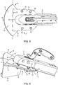
- Fig. 5 shows a trailer hitch guide adaptor 1 for a trailer tongue coupler 2 and attached thereto as seen from a top view.
- the trailer hitch guide adaptor 1 comprises a mounting plate 3 (not to be seen from this view) configured for attachment to the trailer tongue coupler 2 .
- each of the guide plates 6 attached below the mounting plate 3 , each of the guide plates 6 having a guide plate front-end 7 and a guide plate back-end 8 (not to be seen from this view), wherein said guide plates 6 are angled relative to each other, whereby each of the guide plate back-ends 8 converge towards each other; and a third guide plate 9 extending outwards from the mounting plate front-end 5 (not to be seen from this view), the third guide plate 9 having a third guide plate upper surface 10 , wherein the third guide plate upper surface 10 defines an obtuse angle 11 (not to be seen from this view) relative to the mounting plate upper surface 4 (not to be seen from this view).
- the mounting plate 3 further comprises a reinforcement plate 13 attached to the third guide plate upper surface 10 , the reinforcement plate having a reinforcement plate lower surface 14 (not to be seen from this view) and a reinforcement plate front-end 15 being attached to the third guide plate upper surface 10 , such that the reinforcement lower plate surface 14 is parallel to the mounting plate upper surface 4 , wherein the mounting plate 3 and the reinforcement plate 13 are mechanically connected to each other, thereby reinforcing the attachment of the third guide 9 plate to the mounting plate 3 .
- the third guide plate 9 and mounting plate 3 are coupled to each other via screws 16 .
- the third guide plate 9 is further shown with a third guide plate front-end with a curved path 18 .
- the reinforcement plate 13 further comprises a slit 19 with a slit-end 20 facing the reinforcement plate front-end 15 , whereby the slit 19 is able to slide onto an outer surface of the trailer tongue coupler 2 .
- Example 6 Trailer hitch guide adaptor attached to trailer tongue coupler
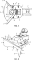
- Fig. 6 shows a trailer hitch guide adaptor 1 for a trailer tongue coupler 2 and attached thereto as seen from a side view.
- the trailer hitch guide adaptor 1 comprises a mounting plate 3 configured for attachment to the trailer tongue coupler 2 .
- the mounting plate 3 has a mounting plate upper surface 4 and a mounting plate front-end 5 ; a pair of guide plates 6 (only one to be seen from this view), each of the guide plates 6 attached below the mounting plate 3 , each of the guide plates 6 having a guide plate front-end 7 and a guide plate back-end 8 , wherein said guide plates 6 are angled relative to each other, whereby each of the guide plate back-ends 8 converge towards each other; and a third guide plate 9 extending outwards from the mounting plate front-end 5 , the third guide plate 9 having a third guide plate upper surface 10 , wherein the third guide plate upper surface 10 defines an obtuse angle 11 relative to the mounting plate upper surface 4.
- the mounting plate further comprising a hole 12 adapted to receive a hitch ball such that the hitch ball is able to connect with a lock inside the trailer tongue coupler 2 .
- the mounting plate 3 further comprises a reinforcement plate 13 attached to the third guide plate upper surface 10 , the reinforcement plate having a reinforcement plate lower surface 14 and a reinforcement plate front-end 15 being attached to the third guide plate upper surface 10 , such that the reinforcement lower plate surface 14 is parallel to the mounting plate upper surface 4 , wherein the mounting plate 3 and the reinforcement plate 13 are mechanically connected to each other, thereby reinforcing the attachment of the third guide 9 plate to the mounting plate 3 .
- the third guide plate 9 and mounting plate 3 are coupled to each other via screws 16 .
- the mounting plate 3 and a the reinforcement plate 13 are separated from each other, thereby forming a slit 17 between the mounting plate 3 and the reinforcement plate 13 , whereby the trailer hitch guide adaptor 1 is able to slide onto an outer surface of the trailer tongue coupler 2 .
- the pair of guide plates 6 is formed by a single plate being bended.
- the third guide plate 9 is further shown with a third guide plate front-end with a curved path 18 .
- the reinforcement plate 13 further comprises a slit 19 with a slit-end 20 facing the reinforcement plate front-end 15 , whereby the slit 19 is able to slide onto an outer surface of the trailer tongue coupler 2 .
- Example 7 Trailer hitch guide adaptor attached to trailer tongue coupler
- Fig. 7 shows a trailer hitch guide adaptor 1 for a trailer tongue coupler 2 and attached thereto as seen from below.
- the trailer hitch guide adaptor 1 comprises a mounting plate 3 configured for attachment to the trailer tongue coupler 2 .
- the mounting plate 3 has a mounting plate upper surface 4 (not to be seen from this view) and a mounting plate front-end 5 (not to be seen from this view); a pair of guide plates 6 , each of the guide plates 6 attached below the mounting plate 3, each of the guide plates 6 having a guide plate front-end 7 .
- the pair of guide plates 6 is formed by a single plate being bended, meaning each of the guide plate back-ends 8 connect to each other.
- the present example shows how the two guide plates 6 form a single-piece guiding-structure.
- a bended section is clearly shown between the guide plate back-ends 8 .
- the guide plates 6 are angled relative to each other, and each of the guide plate back-ends 8 converge in the same plate in the single plate.
- a third guide plate 9 extends outwards from the mounting plate front-end 5 , the third guide plate 9 having a third guide plate upper surface 10 (not to be seen from this view), wherein the third guide plate upper surface 10 defines an obtuse angle 11 (not to be seen from this view) relative to the mounting plate upper surface 4 .
- the mounting plate further comprising a hole 12 adapted to receive a hitch ball such that the hitch ball is able to connect with a lock inside the trailer tongue coupler 2 .
- each of the guide plate back-ends 8 converge such that the mounting plate front-end 5 and said guide plates 7 defines an inscribed circle on a surface below the mounting plate 3 being greater than the diameter of a hitch ball. This allows for the ball to slide on the mounting plate 3 before it enters the hole.
- the distance from the outer perimeter to the mounting plate front-end 5 has a distance of more than 5 mm. Having a certain distance facilitates a reinforced rim around the lock in the trailer tongue coupler 2 .
- the hole is with a rim, wherein the rim is closed.
- the closed rim also provides for stability of the trailer hitch guide adaptor 1 .
- a closed rim might not be used in that integration might provide for stability.
- the third guide plate 9 is further shown with a third guide plate front-end with a curved path 18 .
- Example 8 Trailer hitch guide adaptor attached to trailer tongue coupler
- Fig. 8 shows a trailer hitch guide adaptor 1 for a trailer tongue coupler 2 and attached thereto as seen from a perspective view.
- the trailer hitch guide adaptor 1 comprises a mounting plate 3 configured for attachment to the trailer tongue coupler 2 .
- the mounting plate 3 has a mounting plate upper surface 4 and a mounting plate front-end 5 (not to be seen from this view); a pair of guide plates 6 , each of the guide plates 6 attached below the mounting plate 3 , each of the guide plates 6 having a guide plate front-end 7 and a guide plate back-end 8 , wherein said guide plates 6 are angled relative to each other, whereby each of the guide plate back-ends 8 converge towards each other; and a third guide plate 9 extending outwards from the mounting plate front-end 5 , the third guide plate 9 having a third guide plate upper surface 10 , wherein the third guide plate upper surface 10 defines an obtuse angle 11 relative to the mounting plate upper surface 4 .
- the mounting plate 3 further comprises a reinforcement plate 13 attached to the third guide plate upper surface 10 , the reinforcement plate having a reinforcement plate lower surface 14 and a reinforcement plate front-end 15 (not to be seen from this view) being attached to the third guide plate upper surface 10 , such that the reinforcement lower plate surface 14 is parallel to the mounting plate upper surface 4 , wherein the mounting plate 3 and the reinforcement plate 13 are mechanically connected to each other, thereby reinforcing the attachment of the third guide 9 plate to the mounting plate 3 .
- the third guide plate 9 and mounting plate 3 are coupled to each other via screws 16 .
- the mounting plate 3 and a the reinforcement plate 13 are separated from each other, thereby forming a slit 17 between the mounting plate 3 and the reinforcement plate 13 , whereby the trailer hitch guide adaptor 1 is able to slide onto an outer surface of the trailer tongue coupler 2 .
- the pair of guide plates 6 is formed by a single plate being bended.
- the reinforcement plate 13 further comprises a slit 19 with a slit-end 20 facing the reinforcement plate front-end 15 , whereby the slit 19 is able to slide onto an outer surface of the trailer tongue coupler 2 .
- Example 9 Trailer hitch guide adaptor attached to trailer tongue coupler
- Fig. 9 shows a trailer hitch guide adaptor 1 for a trailer tongue coupler 2 and attached thereto as seen from a side view.
- Fig. 9 shows a trailer tongue coupler with an integrated trailer hitch guide adaptor 2 .
- the trailer hitch guide adaptor 1 comprises a mounting plate 3 attached to the trailer tongue coupler 2 .
- the mounting plate 3 has a mounting plate upper surface 4 and a mounting plate front-end 5 ; a pair of guide plates 6 (only one to be seen from this view), each of the guide plates 6 attached below the mounting plate 3 , each of the guide plates 6 having a guide plate front-end 7 and a guide plate back-end 8 , wherein said guide plates 6 are angled relative to each other, whereby each of the guide plate back-ends 8 converge towards each other; and a third guide plate 9 extending outwards from the mounting plate front-end 5 , the third guide plate 9 having a third guide plate upper surface 10 , wherein the third guide plate upper surface 10 defines an obtuse angle 11 relative to the mounting plate upper surface 4 .
- the pair of guide plates 6 is formed by a single plate being bended.
- the third guide plate 9 is further shown with a third guide plate front-end with a curved path 18 .
- Example 10 Trailer hitch guide adaptor attached to trailer tongue coupler
- Fig. 10 shows a trailer hitch guide adaptor 1 for a trailer tongue coupler 2 and attached thereto as seen from a top view.
- Fig. 9 shows a trailer tongue coupler with an integrated trailer hitch guide adaptor 2 .
- the trailer hitch guide adaptor 1 comprises a mounting plate 3 attached to the trailer tongue coupler 2 .
- the mounting plate 3 has a mounting plate upper surface 4 and a mounting plate front-end 5 ; a pair of guide plates 6 (not to be seen from this view), each of the guide plates 6 attached below the mounting plate 3 , each of the guide plates 6 having a guide plate front-end 7 and a guide plate back-end 8 (not to be seen from this view), wherein said guide plates 6 are angled relative to each other, whereby each of the guide plate back-ends 8 converge towards each other; and a third guide plate 9 extending outwards from the mounting plate front-end 5 , the third guide plate 9 having a third guide plate upper surface 10 , wherein the third guide plate upper surface 10 defines an obtuse angle 11 (not to be seen from this view) relative to the mounting plate upper surface 4 .
- the third guide plate 9 is further shown with a third guide plate front-end with a curved path 18 .
Landscapes
- Engineering & Computer Science (AREA)
- Transportation (AREA)
- Mechanical Engineering (AREA)
- Quick-Acting Or Multi-Walled Pipe Joints (AREA)
- Agricultural Machines (AREA)
- Platform Screen Doors And Railroad Systems (AREA)
- Earth Drilling (AREA)
- Aiming, Guidance, Guns With A Light Source, Armor, Camouflage, And Targets (AREA)
- Electric Cable Arrangement Between Relatively Moving Parts (AREA)
- Fittings On The Vehicle Exterior For Carrying Loads, And Devices For Holding Or Mounting Articles (AREA)
- Buckles (AREA)
- Hooks, Suction Cups, And Attachment By Adhesive Means (AREA)
- Vending Machines For Individual Products (AREA)
- Handcart (AREA)
- Vehicle Waterproofing, Decoration, And Sanitation Devices (AREA)
Description
- The present disclosure relates to a trailer hitch guide adaptor, more specifically to be mounted on a trailer tongue coupler, i.e. on part of a trailer. The disclosure further relates to a trailer tongue coupler attached with the trailer hitch guide adaptor.
- Trailer tongue couplers on trailers typically have a hole adapted to receive a hitch ball, typically placed on a towing vehicle, or a car, such that the hitch ball is able to connect with a lock inside the trailer tongue coupler, thereby connecting the towing vehicle to the trailer. Connecting the hitch ball to the hole on the trailer tongue coupler requires a lot a driving in reverse. The driver needs to carefully drive the car towards the trailer, more specifically towards the trailer tongue. Depending on the reverse driving skills of the driver, the hitch ball is typically placed within a meter of the hole of the trailer tongue. Hereafter, the driver might be able to step out of the car and grab the trailer tongue, such that the driver pulls and/or pushes the trailer by the trailer tongue the last meter and might be able to place the hole above the hitch ball, release the trailer tongue, and thereby connect the trailer to the car. The described manoeuvre might be possible if the driver is strong and/or the trailer is light weight. Nevertheless, the manoeuvres might not be desirable and even dangerous. Furthermore, for heavy trailers, and regardless of how strong the driver is, the described manoeuvre might be impossible.
- A problem is that it is not easy and/or impossible to connect a trailer to a car. One solution to this problem is to provide a trailer tongue coupler with two guide plates, such that the hitch ball is guided towards the hole of the trailer tongue coupler. However, using the trailer tongue couplers with two guide plates is problematic because their construction is weak, and might easily break, especially when a heavy car bumps into the guide plates. Furthermore, getting the trailer tongue couplers with two guide plates is typically an expensive solution. Thus, there is a need for a solidly constructed trailer tongue coupler. Furthermore, there is also a need for providing a low cost trailer tongue coupler. A trailer hitch guide adaptor according to the preamble of
claim 1 is known fromUS 6 179 318 B1 . - The present disclosure relates in a first aspect to a trailer hitch guide adaptor for a trailer tongue coupler, comprising: a mounting plate configured for attachment to the trailer tongue coupler, the mounting plate having an mounting plate upper-surface and a mounting plate front-end; a pair of guide plates, each of the guide plates attached below the mounting plate, each of the guide plates having a guide plate front-end and a guide plate back-end, wherein said guide plates are angled relative to each other, whereby each of the guide plate back-ends converge towards each other and towards a converging line; and a third guide plate extending outwards from the mounting plate front-end, the third guide plate having a third guide plate upper surface, wherein the third guide plate upper surface defines an obtuse angle relative to the mounting plate upper surface, such that a hitch ball is able to be guided towards the mounting plate front-end via the third guide plate, and/or from below the mounting plate and towards the guide plate back ends via one of the guide plates attached below the mounting plate.
- By the present trailer hitch guide adaptor is first of all provided means for providing a low cost trailer tongue coupler, in that the just presented trailer hitch guide adaptor is able to convert a low cost trailer tongue coupler to a trailer hitch guide, simply by mounting the trailer hitch guide adaptor to an existing trailer tongue coupler. Furthermore, by the present trailer hitch guide adaptor, when mounted to a trailer tongue coupler, is also provided a solidly constructed trailer tongue coupler that is able to guide a hitch ball into a position, where the hitch ball is able to connect to the trailer tongue coupler. In particular because there is a third guide plate extending outwards from the mounting plate front-end, there is facilitated a solid construction. The third guide plate serves per se as an extra guidance of the hitch ball. Due to the construction as here described, the third guide plate has a connection from the mounting plate, i.e. from a line on the mounting plate front-end, which facilitates that force from a hitch ball is transferred to the mounting plate via several points on that line. Preferably, the mounting plate front-end defined a width of more than 5 cm, such as more than 10 cm, or such as more than 15 cm.
- A third guide plate is known from designs of hitch guides located on cars, neither on an adaptor for a trailer tongue coupler nor on a trailer tongue coupler. However, on these designs, the third guide plate typically extend from a converging point, thus not a line as in the present invention. Accordingly, hitch guides with a third guide plate located on cars have been constructions rather weakly. The present invention provides for a very robust construction. Furthermore, because the guide plates are attached below the mounting plate, and the third guide plate extends upwards from the mounting plate, the third guide plate also serves to protect the trailer tongue coupler from the hitch ball during connection.
- Furthermore, since the hitch ball is first guided towards the mounting plate front-end via the third guide plate, and secondly from below the mounting plate and towards the guide plate back ends via one of the guide plates attached below the mounting plate, there is provided a design, where a hitch ball in two-steps is guided towards the point of interest, in this case towards the guide plate back ends. A two-step guidance as here described provides for a more efficient guidance than single-step guidance, for example as is the case with previous designs having only guide plates that all start in one plane and end in another plane.
- Due to the guide plates being attached below the mounting plate, the guide plates are not visible from above. Thus, the guide plates are not physically accessible from above. Therefore, the guide plates do not easily get in contact with physical objects from above, for example hands and/or other body parts handling the mounting plate.
- In some embodiments, the pair of guide plates is completely covered by the mounting plate. In other words, the guide plate front-ends are below the mounting plate. In this way, any corners on the guide plate front-ends are not accessible from above, making the invention a safe adaptor and/or a safe trailer tongue coupler.
- In a preferred embodiment of the trailer hitch guide adaptor, the guide plate back-ends are connected to each other at or around the converging line to form a single-piece guiding-structure. The single-piece guiding-structure may for example be formed by the two guide plates being connected to each other, such as by welding or glue. Alternatively, the single-piece guiding-structure may be formed by a single plate, for example a single plate being bended. In other words, the single-piece guiding structure may form a V-shape. The V-shape is seen from above, where the connection of the two guide plates either form a soft or a sharp connection, i.e. a connection that either forms a corner or a curve.
- The single-piece guiding-structure is more robust than two separate plates, and also provides fewer edges than two separate plates. Accordingly, the invention is more robust and safer to use.
- The guide plate back-ends may be connected through an additional section, such as a bended section. As just described, the single-piece guiding structure may be formed by a single plate being bended, such that the bended section is part of the single plate. Alternatively, the bended section may be a separate plate being bended and connected to the each of the guide plate back-ends. The three plates may then form the single-piece guiding-structure by for example welding the three plates together.
- By having a single-piece guiding structure, the connection of the two guide plates, proves a reinforced section. The reinforced section is where the two guide plates are connected. Thus, the reinforced section may be where the two guide plates are welded together, or it may be at the bended section.
- The inventors of the present invention have found that the single-piece guiding structure provides several advantages, as will be described in the following.
- For example, when connecting a trailer ball (such as located on a car), to a trailer, an overrun brake is commonly installed on the trailer, more specifically on the trailer tongue coupler. Drivers of the car, typically rely on the overrun brake, and are thus not afraid of reversing the car with the hitch ball at great speed into the connection point of trailer. If two separate guide plates are used instead of a single-piece guiding structure, the inventors realized that such two guide plates would easily bend by the impact of the hitch ball. Thereby, the hitch ball would continue with great impact into other parts of the trailer, i.e. behind the guide plates, and in many cases destroy both the two separate plates and the other parts of the trailer. The present invention avoids this by having the single-piece guiding-structure.
- Further, when a hitch ball is connected to a trailer using the trailer hitch guide adaptor according to the present invention, the trailer may either have an overrun brake installed on the trailer or not. In cases, where the trailer does not have an overrun brake installed, the single-piece guiding-structure also provides for a safe connection that is able to withstand the impact of the trailer without destroying the two guide plates. In cases, where the trailer has an overrun brake installed, and the overrun brake is not working properly, the single-piece guiding-structure also provides for a safe connection enabling impact of the trailer without destroying the two guide plates. As explained above, the same case is present even if the overrun brake is working properly.
- Accordingly, the single-piece guiding-structure facilitates both the effect of guiding the hitch ball in place, and the effect of stopping the hitch ball once the hitch ball is in place.
- All in all, the present invention provides an improved and very safe trailer hitch guide adaptor as is also the objective of the present invention.
- Further, the present invention provides for a non-complex design that is easy to manufacture, in particular because the two guide plates are formed as a single-piece guiding structure. Accordingly, the present invention provides for a trailer tongue coupler that is able to be manufactured at low cost in comparison to more complex designs.
- In a second aspect of the present disclosure there is provided a trailer tongue coupler comprising the trailer hitch guide adaptor as described above.
- Advantages of the here described trailer tongue coupler includes the same advantages as for the trailer hitch guide adaptor. An additional advantage of having in attached in one way or another is that it provides for a robust construction of a trailer tongue coupler.
-
-
Fig. 1 shows an embodiment of the trailer hitch guide adaptor according to the invention from a top view. -
Fig. 2 shows an embodiment of the trailer hitch guide adaptor according to the invention from a side view. -
Fig. 3 shows an embodiment of the trailer hitch guide adaptor according to the invention as seen from below. -
Fig. 4 shows an embodiment of the trailer hitch guide adaptor according to the invention from a perspective view. -
Fig. 5 shows an embodiment of the trailer hitch guide adaptor attached to a trailer tongue coupler according to the invention from a top view. -
Fig. 6 shows an embodiment of the trailer hitch guide adaptor attached to a trailer tongue coupler according to the invention from a side view. -
Fig. 7 shows an embodiment of the trailer hitch guide adaptor attached to a trailer tongue coupler according to the invention as seen from below. -
Fig. 8 shows an embodiment of the trailer hitch guide adaptor attached to a trailer tongue coupler according to the invention from a perspective view. -
Fig. 9 shows an embodiment of the trailer hitch guide adaptor attached to a trailer tongue coupler according to the invention from a side view. -
Fig. 10 shows an embodiment of the trailer hitch guide adaptor attached to a trailer tongue coupler according to the invention as seen from a top view. - The present disclosure relates in one aspect to a trailer hitch guide adaptor. The trailer hitch guide adaptor comprises several plates. These plates are described in further details below.
- In one embodiment of the trailer hitch guide adaptor, the mounting plate further comprising a hole adapted to receive a hitch ball such that the hitch ball is able to connect with a lock inside the trailer tongue coupler. The hole may have any shape, such as circular oval, rectangular, and/or combined shapes. In some embodiments, the hole is a slit. The hole may be with a rim, wherein the rim is closed. In some embodiments, the rim is open.
- According to the invention, the mounting plate further comprises a reinforcement plate attached to the third guide plate upper surface, the reinforcement plate having a reinforcement plate lower surface and a reinforcement plate front-end being attached to the third guide plate upper surface, such that the reinforcement lower plate surface is parallel to the mounting plate upper surface, wherein the mounting plate and the reinforcement plate are mechanically connected to each other, thereby reinforcing the attachment of the third guide plate to the mounting plate. As previously described, the third guide plate is for protecting the trailer tongue coupler, and the reinforcement plate adds further protection to the trailer tongue coupler.
- The reinforcement plate may be connected to the mounting plate by various means. In some embodiments, the reinforcement plate and the mounting plate is mechanically coupled to each other via fastening means, such as screws and/or welded material and/or glue. In other embodiments, the reinforcement plate and the mounting plate is connected to each other via a connecting plate. The connecting plate and the mounting plate may be made of one piece of material, for example to provide a solid construction.
- In some embodiments of the trailer hitch guide adaptor, the reinforcement plate further comprises a slit with a slit-end facing the reinforcement plate front-end, whereby the slit is able to slide onto an outer surface of the trailer tongue coupler. This may provide for easy attachment of the trailer hitch guide adaptor to the trailer tongue coupler.
- In a preferred embodiment of the trailer hitch guide adaptor, the mounting plate and a the reinforcement plate are separated from each other, thereby forming a gap between the mounting plate and the reinforcement plate, whereby the trailer hitch guide adaptor is able to slide onto an outer surface of the trailer tongue coupler. This may also provide for easy attachment of the trailer hitch guide adaptor to the trailer tongue coupler.
- In one embodiment of the trailer hitch guide adaptor, the pair of guide plates is angled relative to each other with an angle between 60 and 120 degrees, such as around 90 degrees or such as around 100 degrees.
- In another embodiment of the trailer hitch guide adaptor, each of the guide plate back-ends converge such that the mounting plate front-end and said guide plates defines an inscribed circle on a surface below the mounting plate with a diameter greater than 4 cm, such as greater than 5 cm, or such as greater than 6 cm. With these diameters, the inscribed circle is equal to or greater than the diameter of the hitch ball. From this, it is clear that the hitch ball is to be guided below the mounting plate, such that the hitch ball connects to the trailer tongue coupler though the mounting plate. Advantages of the inventions are indeed related to solid construction but also solid connections. As here described, the connection is via the mounting plate, and this adds strength to the connection. In other words, the adaptor strengthens the trailer tongue coupler, in particular around the hole of the trailer tongue coupler.
- I yet another embodiment of the trailer hitch guide adaptor, said pair of guide plates are a single plate being bended. Such a construction may first of all be more robust than two separate plates, but may also provide fewer edges, making the invention even safer to use.
- In one embodiment of the trailer hitch guide adaptor, the obtuse angle is between 120 and 150 degrees, such as around 130 degrees, such as around 135 degrees, or such as around 140 degrees.
- According to the invention, the third guide plate has a third guide plate front-end with a curved path. As previously described, advantages of the present invention relate to safe use, and by having a curved path, sharp corners and/or edges are avoided. Furthermore, since the third guide plate is on the trailer hitch guide being connected to the trailer tongue coupler, and this follows the car as it drives, in particular turns around a corner, the curved path on the third guide plate is provides for the trailer hitch guide adaptor to be as close as possible to the car as possible during turning. In other words, the distance from the curved path to the back of the car is kept constant regardless of which direction the car drives. Thus, the curved path provides for a compact, hence more robust design.
- In a preferred embodiment of the trailer hitch guide adaptor, at least the mounting plate and the third guide plate are formed by a single piece. This too, provides for a solid construction.
- According to the second aspect of the invention, an embodiment of the trailer tongue coupler is such that the trailer hitch guide adaptor is permanently attached to the trailer tongue coupler by welding. In other words, the present invention provides a trailer tongue coupler for a trailer. The trailer tongue coupler comprises guide plates with the same features as described for the trailer hitch guide adaptor.
- In a preferred embodiment of the trailer tongue coupler, the trailer tongue coupler and trailer hitch guide adaptor are integrated to each other. In other words, the trailer hitch guide adaptor is an integral part of the trailer tongue coupler.
-
Fig. 1 shows a trailerhitch guide adaptor 1 for a trailer tongue coupler 2 (not present in this example) as seen from a top view. The trailerhitch guide adaptor 1 comprises a mounting plate 3 (not to be seen from this view) configured for attachment to thetrailer tongue coupler 2. There is a pair ofguide plates 6, each of theguide plates 6 attached below the mountingplate 3, each of theguide plates 6 having a guide plate front-end 7 and a guide plate back-end 8 (not to be seen from this view), wherein saidguide plates 6 are angled relative to each other, whereby each of the guide plate back-ends 8 converge towards each other; and athird guide plate 9 extending outwards from the mounting plate front-end 5 (not to be seen from this view), thethird guide plate 9 having a third guide plateupper surface 10, wherein the third guide plateupper surface 10 defines an obtuse angle 11 (not to be seen from this view) relative to the mounting plate upper surface 4 (not to be seen from this view). The mountingplate 3 further comprises areinforcement plate 13 attached to the third guide plateupper surface 10, the reinforcement plate having a reinforcement plate lower surface 14 (not to be seen from this view) and a reinforcement plate front-end 15 being attached to the third guide plateupper surface 10, such that the reinforcementlower plate surface 14 is parallel to the mounting plateupper surface 4, wherein the mountingplate 3 and thereinforcement plate 13 are mechanically connected to each other, thereby reinforcing the attachment of thethird guide 9 plate to the mountingplate 3. In the embodiment as shown, thethird guide plate 9 and mountingplate 3 are coupled to each other via screws 16. Thethird guide plate 9 is further shown with a third guide plate front-end with acurved path 18. Thereinforcement plate 13 further comprises aslit 19 with a slit-end 20 facing the reinforcement plate front-end 15, whereby theslit 19 is able to slide onto an outer surface of thetrailer tongue coupler 2. -
Fig. 2 shows a trailerhitch guide adaptor 1 for a trailer tongue coupler 2 (not present in this example) as seen from a side view. The trailerhitch guide adaptor 1 comprises a mountingplate 3 configured for attachment to thetrailer tongue coupler 2. The mountingplate 3 has a mounting plateupper surface 4 and a mounting plate front-end 5; a pair of guide plates 6 (only one to be seen from this view), each of theguide plates 6 attached below the mountingplate 3, each of theguide plates 6 having a guide plate front-end 7 and a guide plate back-end 8, wherein saidguide plates 6 are angled relative to each other, whereby each of the guide plate back-ends 8 converge towards each other; and athird guide plate 9 extending outwards from the mounting plate front-end 5, thethird guide plate 9 having a third guide plateupper surface 10, wherein the third guide plateupper surface 10 defines anobtuse angle 11 relative to the mounting plateupper surface 4. The mounting plate further comprising ahole 12 adapted to receive a hitch ball such that the hitch ball is able to connect with a lock inside thetrailer tongue coupler 2. The mountingplate 3 further comprises areinforcement plate 13 attached to the third guide plateupper surface 10, the reinforcement plate having a reinforcement platelower surface 14 and a reinforcement plate front-end 15 being attached to the third guide plateupper surface 10, such that the reinforcementlower plate surface 14 is parallel to the mounting plateupper surface 4, wherein the mountingplate 3 and thereinforcement plate 13 are mechanically connected to each other, thereby reinforcing the attachment of thethird guide 9 plate to the mountingplate 3. In the embodiment as shown, thethird guide plate 9 and mountingplate 3 are coupled to each other via screws 16. The mountingplate 3 and a thereinforcement plate 13 are separated from each other, thereby forming aslit 17 between the mountingplate 3 and thereinforcement plate 13, whereby the trailerhitch guide adaptor 1 is able to slide onto an outer surface of thetrailer tongue coupler 2. As can also be seen from the present embodiment, the pair ofguide plates 6 is formed by a single plate being bended. Thethird guide plate 9 is further shown with a third guide plate front-end with acurved path 18. Thereinforcement plate 13 further comprises aslit 19 with a slit-end 20 facing the reinforcement plate front-end 15, whereby theslit 19 is able to slide onto an outer surface of thetrailer tongue coupler 2. -
Fig. 3 shows a trailerhitch guide adaptor 1 for a trailer tongue coupler 2 (not present in this example) as seen from below. The trailerhitch guide adaptor 1 comprises a mountingplate 3 configured for attachment to thetrailer tongue coupler 2. The mountingplate 3 has a mounting plate upper surface 4 (not to be seen from this view) and a mounting plate front-end 5 (not to be seen from this view); a pair ofguide plates 6, each of theguide plates 6 attached below the mountingplate 3, each of theguide plates 6 having a guide plate front-end 7. The pair ofguide plates 6 is formed by a single plate being bended, meaning each of the guide plate back-ends 8 connect to each other. Thus, the present example shows how the twoguide plates 6 form a single-piece guiding-structure. A bended section is clearly shown between the guide plate back-ends 8. Theguide plates 6 are angled relative to each other, and each of the guide plate back-ends 8 converge in the same plate in the single plate. Athird guide plate 9 extends outwards from the mounting plate front-end 5, thethird guide plate 9 having a third guide plate upper surface 10 (not to be seen from this view), wherein the third guide plateupper surface 10 defines an obtuse angle 11 (not to be seen from this view) relative to the mounting plateupper surface 4. The mounting plate further comprising ahole 12 adapted to receive a hitch ball such that the hitch ball is able to connect with a lock inside thetrailer tongue coupler 2. As can be seen, the hole is much larger than the hitch ball because the hole is also adapted to allow for the lock to operate, i.e. move up and down in the hole. From this view, it can be seen that each of the guide plate back-ends 8 converge such that the mounting plate front-end 5 and saidguide plates 7 defines an inscribed circle on a surface below the mountingplate 3 being greater than the diameter of a hitch ball. This allows for the ball to slide on the mountingplate 3 before it enters the hole. The distance from the outer perimeter to the mounting plate front-end 5 has a distance of more than 5 mm. Having a certain distance facilitates a reinforced rim around the lock in thetrailer tongue coupler 2. As can also be seen, the hole is with a rim, wherein the rim is closed. The closed rim also provides for stability of the trailerhitch guide adaptor 1. However, if the trailer hitch guide adaptor is an integral part of the trailer tongue, a closed rim might not be used in that integration might provide for stability. Thethird guide plate 9 is further shown with a third guide plate front-end with acurved path 18. -
Fig. 4 shows a trailerhitch guide adaptor 1 for a trailer tongue coupler 2 (not present in this example) as seen from a perspective view. The trailerhitch guide adaptor 1 comprises a mountingplate 3 configured for attachment to thetrailer tongue coupler 2. The mountingplate 3 has a mounting plateupper surface 4 and a mounting plate front-end 5 (not to be seen from this view); a pair ofguide plates 6, each of theguide plates 6 attached below the mountingplate 3, each of theguide plates 6 having a guide plate front-end 7 and a guide plate back-end 8, wherein saidguide plates 6 are angled relative to each other, whereby each of the guide plate back-ends 8 converge towards each other; and athird guide plate 9 extending outwards from the mounting plate front-end 5, thethird guide plate 9 having a third guide plateupper surface 10, wherein the third guide plateupper surface 10 defines anobtuse angle 11 relative to the mounting plateupper surface 4. The mountingplate 3 further comprises areinforcement plate 13 attached to the third guide plateupper surface 10, the reinforcement plate having a reinforcement platelower surface 14 and a reinforcement plate front-end 15 (not to be seen from this view) being attached to the third guide plateupper surface 10, such that the reinforcementlower plate surface 14 is parallel to the mounting plateupper surface 4, wherein the mountingplate 3 and thereinforcement plate 13 are mechanically connected to each other, thereby reinforcing the attachment of thethird guide 9 plate to the mountingplate 3. In the embodiment as shown, thethird guide plate 9 and mountingplate 3 are coupled to each other via screws 16. The mountingplate 3 and a thereinforcement plate 13 are separated from each other, thereby forming aslit 17 between the mountingplate 3 and thereinforcement plate 13, whereby the trailerhitch guide adaptor 1 is able to slide onto an outer surface of thetrailer tongue coupler 2. As can also be seen from the present embodiment, the pair ofguide plates 6 is formed by a single plate being bended. Thereinforcement plate 13 further comprises aslit 19 with a slit-end 20 facing the reinforcement plate front-end 15, whereby theslit 19 is able to slide onto an outer surface of thetrailer tongue coupler 2. -
Fig. 5 shows a trailerhitch guide adaptor 1 for atrailer tongue coupler 2 and attached thereto as seen from a top view. The trailerhitch guide adaptor 1 comprises a mounting plate 3 (not to be seen from this view) configured for attachment to thetrailer tongue coupler 2. There is a pair ofguide plates 6, each of theguide plates 6 attached below the mountingplate 3, each of theguide plates 6 having a guide plate front-end 7 and a guide plate back-end 8 (not to be seen from this view), wherein saidguide plates 6 are angled relative to each other, whereby each of the guide plate back-ends 8 converge towards each other; and athird guide plate 9 extending outwards from the mounting plate front-end 5 (not to be seen from this view), thethird guide plate 9 having a third guide plateupper surface 10, wherein the third guide plateupper surface 10 defines an obtuse angle 11 (not to be seen from this view) relative to the mounting plate upper surface 4 (not to be seen from this view). The mountingplate 3 further comprises areinforcement plate 13 attached to the third guide plateupper surface 10, the reinforcement plate having a reinforcement plate lower surface 14 (not to be seen from this view) and a reinforcement plate front-end 15 being attached to the third guide plateupper surface 10, such that the reinforcementlower plate surface 14 is parallel to the mounting plateupper surface 4, wherein the mountingplate 3 and thereinforcement plate 13 are mechanically connected to each other, thereby reinforcing the attachment of thethird guide 9 plate to the mountingplate 3. In the embodiment as shown, thethird guide plate 9 and mountingplate 3 are coupled to each other via screws 16. Thethird guide plate 9 is further shown with a third guide plate front-end with acurved path 18. Thereinforcement plate 13 further comprises aslit 19 with a slit-end 20 facing the reinforcement plate front-end 15, whereby theslit 19 is able to slide onto an outer surface of thetrailer tongue coupler 2. -
Fig. 6 shows a trailerhitch guide adaptor 1 for atrailer tongue coupler 2 and attached thereto as seen from a side view. The trailerhitch guide adaptor 1 comprises a mountingplate 3 configured for attachment to thetrailer tongue coupler 2. The mountingplate 3 has a mounting plateupper surface 4 and a mounting plate front-end 5; a pair of guide plates 6 (only one to be seen from this view), each of theguide plates 6 attached below the mountingplate 3, each of theguide plates 6 having a guide plate front-end 7 and a guide plate back-end 8, wherein saidguide plates 6 are angled relative to each other, whereby each of the guide plate back-ends 8 converge towards each other; and athird guide plate 9 extending outwards from the mounting plate front-end 5, thethird guide plate 9 having a third guide plateupper surface 10, wherein the third guide plateupper surface 10 defines anobtuse angle 11 relative to the mounting plateupper surface 4. The mounting plate further comprising ahole 12 adapted to receive a hitch ball such that the hitch ball is able to connect with a lock inside thetrailer tongue coupler 2. The mountingplate 3 further comprises areinforcement plate 13 attached to the third guide plateupper surface 10, the reinforcement plate having a reinforcement platelower surface 14 and a reinforcement plate front-end 15 being attached to the third guide plateupper surface 10, such that the reinforcementlower plate surface 14 is parallel to the mounting plateupper surface 4, wherein the mountingplate 3 and thereinforcement plate 13 are mechanically connected to each other, thereby reinforcing the attachment of thethird guide 9 plate to the mountingplate 3. In the embodiment as shown, thethird guide plate 9 and mountingplate 3 are coupled to each other via screws 16. The mountingplate 3 and a thereinforcement plate 13 are separated from each other, thereby forming aslit 17 between the mountingplate 3 and thereinforcement plate 13, whereby the trailerhitch guide adaptor 1 is able to slide onto an outer surface of thetrailer tongue coupler 2. As can also be seen from the present embodiment, the pair ofguide plates 6 is formed by a single plate being bended. Thethird guide plate 9 is further shown with a third guide plate front-end with acurved path 18. Thereinforcement plate 13 further comprises aslit 19 with a slit-end 20 facing the reinforcement plate front-end 15, whereby theslit 19 is able to slide onto an outer surface of thetrailer tongue coupler 2. -
Fig. 7 shows a trailerhitch guide adaptor 1 for atrailer tongue coupler 2 and attached thereto as seen from below. The trailerhitch guide adaptor 1 comprises a mountingplate 3 configured for attachment to thetrailer tongue coupler 2. The mountingplate 3 has a mounting plate upper surface 4 (not to be seen from this view) and a mounting plate front-end 5 (not to be seen from this view); a pair ofguide plates 6, each of theguide plates 6 attached below the mountingplate 3, each of theguide plates 6 having a guide plate front-end 7. The pair ofguide plates 6 is formed by a single plate being bended, meaning each of the guide plate back-ends 8 connect to each other. Thus, the present example shows how the twoguide plates 6 form a single-piece guiding-structure. A bended section is clearly shown between the guide plate back-ends 8. Theguide plates 6 are angled relative to each other, and each of the guide plate back-ends 8 converge in the same plate in the single plate. Athird guide plate 9 extends outwards from the mounting plate front-end 5, thethird guide plate 9 having a third guide plate upper surface 10 (not to be seen from this view), wherein the third guide plateupper surface 10 defines an obtuse angle 11 (not to be seen from this view) relative to the mounting plateupper surface 4. The mounting plate further comprising ahole 12 adapted to receive a hitch ball such that the hitch ball is able to connect with a lock inside thetrailer tongue coupler 2. As can be seen, the hole is much larger than the hitch ball because the hole is also adapted to allow for the lock to operate, i.e. move up and down in the hole. From this view, it can be seen that each of the guide plate back-ends 8 converge such that the mounting plate front-end 5 and saidguide plates 7 defines an inscribed circle on a surface below the mountingplate 3 being greater than the diameter of a hitch ball. This allows for the ball to slide on the mountingplate 3 before it enters the hole. The distance from the outer perimeter to the mounting plate front-end 5 has a distance of more than 5 mm. Having a certain distance facilitates a reinforced rim around the lock in thetrailer tongue coupler 2. As can also be seen, the hole is with a rim, wherein the rim is closed. The closed rim also provides for stability of the trailerhitch guide adaptor 1. However, if the trailer hitch guide adaptor is an integral part of the trailer tongue, a closed rim might not be used in that integration might provide for stability. Thethird guide plate 9 is further shown with a third guide plate front-end with acurved path 18. -
Fig. 8 shows a trailerhitch guide adaptor 1 for atrailer tongue coupler 2 and attached thereto as seen from a perspective view. The trailerhitch guide adaptor 1 comprises a mountingplate 3 configured for attachment to thetrailer tongue coupler 2. The mountingplate 3 has a mounting plateupper surface 4 and a mounting plate front-end 5 (not to be seen from this view); a pair ofguide plates 6, each of theguide plates 6 attached below the mountingplate 3, each of theguide plates 6 having a guide plate front-end 7 and a guide plate back-end 8, wherein saidguide plates 6 are angled relative to each other, whereby each of the guide plate back-ends 8 converge towards each other; and athird guide plate 9 extending outwards from the mounting plate front-end 5, thethird guide plate 9 having a third guide plateupper surface 10, wherein the third guide plateupper surface 10 defines anobtuse angle 11 relative to the mounting plateupper surface 4. The mountingplate 3 further comprises areinforcement plate 13 attached to the third guide plateupper surface 10, the reinforcement plate having a reinforcement platelower surface 14 and a reinforcement plate front-end 15 (not to be seen from this view) being attached to the third guide plateupper surface 10, such that the reinforcementlower plate surface 14 is parallel to the mounting plateupper surface 4, wherein the mountingplate 3 and thereinforcement plate 13 are mechanically connected to each other, thereby reinforcing the attachment of thethird guide 9 plate to the mountingplate 3. In the embodiment as shown, thethird guide plate 9 and mountingplate 3 are coupled to each other via screws 16. The mountingplate 3 and a thereinforcement plate 13 are separated from each other, thereby forming aslit 17 between the mountingplate 3 and thereinforcement plate 13, whereby the trailerhitch guide adaptor 1 is able to slide onto an outer surface of thetrailer tongue coupler 2. As can also be seen from the present embodiment, the pair ofguide plates 6 is formed by a single plate being bended. Thereinforcement plate 13 further comprises aslit 19 with a slit-end 20 facing the reinforcement plate front-end 15, whereby theslit 19 is able to slide onto an outer surface of thetrailer tongue coupler 2. -
Fig. 9 shows a trailerhitch guide adaptor 1 for atrailer tongue coupler 2 and attached thereto as seen from a side view. In other words,Fig. 9 shows a trailer tongue coupler with an integrated trailerhitch guide adaptor 2. The trailerhitch guide adaptor 1 comprises a mountingplate 3 attached to thetrailer tongue coupler 2. The mountingplate 3 has a mounting plateupper surface 4 and a mounting plate front-end 5; a pair of guide plates 6 (only one to be seen from this view), each of theguide plates 6 attached below the mountingplate 3, each of theguide plates 6 having a guide plate front-end 7 and a guide plate back-end 8, wherein saidguide plates 6 are angled relative to each other, whereby each of the guide plate back-ends 8 converge towards each other; and athird guide plate 9 extending outwards from the mounting plate front-end 5, thethird guide plate 9 having a third guide plateupper surface 10, wherein the third guide plateupper surface 10 defines anobtuse angle 11 relative to the mounting plateupper surface 4. As can also be seen from the present embodiment, the pair ofguide plates 6 is formed by a single plate being bended. Thethird guide plate 9 is further shown with a third guide plate front-end with acurved path 18. -
Fig. 10 shows a trailerhitch guide adaptor 1 for atrailer tongue coupler 2 and attached thereto as seen from a top view. In other words,Fig. 9 shows a trailer tongue coupler with an integrated trailerhitch guide adaptor 2. The trailerhitch guide adaptor 1 comprises a mountingplate 3 attached to thetrailer tongue coupler 2. The mountingplate 3 has a mounting plateupper surface 4 and a mounting plate front-end 5; a pair of guide plates 6 (not to be seen from this view), each of theguide plates 6 attached below the mountingplate 3, each of theguide plates 6 having a guide plate front-end 7 and a guide plate back-end 8 (not to be seen from this view), wherein saidguide plates 6 are angled relative to each other, whereby each of the guide plate back-ends 8 converge towards each other; and athird guide plate 9 extending outwards from the mounting plate front-end 5, thethird guide plate 9 having a third guide plateupper surface 10, wherein the third guide plateupper surface 10 defines an obtuse angle 11 (not to be seen from this view) relative to the mounting plateupper surface 4. Thethird guide plate 9 is further shown with a third guide plate front-end with acurved path 18.
Claims (13)
- A trailer hitch guide adaptor (1) for a trailer tongue coupler (2), comprising:- a mounting plate (3) configured for attachment to the trailer tongue coupler (2), the mounting plate (3) having an mounting plate upper-surface (4) and a mounting plate front-end (5);- a pair of guide plates (6), each of the guide plates attached below the mounting plate (3), each of the guide plates having a guide plate front-end (7) and a guide plate back-end (8), wherein said guide plates are angled relative to each other, whereby each of the guide plate back-ends (8) converge towards each other and towards an intersection line, and wherein the guide plate back-ends are connected to each other at or around the intersection line to form a single-piece guiding-structure; and- a third guide plate (9) extending outwards from the mounting plate front-end (5), the third guide plate (9) having a third guide plate upper surface (10), wherein the third guide plate upper surface (10) defines an obtuse angle (11) relative to the mounting plate upper surface (4),such that a hitch ball is able to be guided towards the mounting plate front-end (5) via the third guide plate (9), and/or from below the mounting plate (4) and towards the guide plate back ends (8) via one of the guide plates attached below the mounting plate (3); and characterised by the third guide plate (9) having a third guide plate front-end with a curved path and bya reinforcement plate (13) attached to the third guide plate upper surface (10), the reinforcement plate (13) having a reinforcement plate lower surface (14) and a reinforcement plate front-end (15) being attached to the third guide plate upper surface (10), such that the reinforcement lower plate surface (14) is parallel to the mounting plate upper surface (4), wherein the mounting plate (3) and the reinforcement plate (13) are mechanically coupled to each other, thereby reinforcing the attachment of the third guide plate (9) to the mounting plate (3).
- The trailer hitch guide adaptor (1) according to claim 1, wherein the mounting plate (3) further comprising a hole (12) adapted to receive a hitch ball such that the hitch ball is able to connect with a lock inside the trailer tongue coupler (2).
- The trailer hitch guide adaptor (1) according any of the preceeding claims, wherein the mounting plate (3) and the reinforcement plate (13) are mechanically coupled to each other via fastening means, such as screws (16) and/or welded material and/or glue.
- The trailer hitch guide adaptor (1) according any of the preceeding claims, wherein the mounting plate (3) and the reinforcement plate (13) are mechanically coupled to each other via a connecting plate, such that the connecting plate is a plate between the reinforcement plate (13) and the mounting plate (3).
- The trailer hitch guide adaptor (1) according to claim 4, wherein the reinforcement plate (13), the connecting plate and the mounting plate (3) are made of one piece of material.
- The trailer hitch guide adaptor according to any of the preceeding claims, wherein the reinforcement plate (13) further comprising a slit (19) with a slit-end (20) facing the reinforcement plate front-end (15), whereby the slit (19) is able to slide onto an outer surface of the trailer tongue coupler (2).
- The trailer hitch guide adaptor (1) according to any of the preceeding claims, wherein the mounting plate (3) and the reinforcement plate (13) are separated from each other, thereby forming a gap between the mounting plate (3) and the reinforcement plate (13), whereby the trailer hitch guide adaptor (1) is able to slide onto an outer surface of the trailer tongue coupler (2).
- The trailer hitch guide adaptor (1) according to any of the preceding claims,
wherein the pair of guide plates (6) is angled relative to each other with an angle between 60 and 120 degrees, such as around 90 degrees or such as around 100 degrees. - The trailer hitch guide adaptor (1) according to any of the preceding claims,
wherein each of the guide plate back-ends (8) converge such that the mounting plate front-end (15) and said guide plates (8) define an inscribed circle on a surface below the mounting plate (3) with a diameter greater than 4 cm, such as greater than 5 cm, or such as greater than 6 cm. - The trailer hitch guide adaptor (1) according to any of the preceding claims, wherein the obtuse angle (11) is between 120 and 150 degrees, such as around 130 degrees, such as around 135 degrees, or such as around 140 degrees.
- The trailer hitch guide adaptor (1) according to any of the preceding claims, wherein at least the mounting plate (3) and the third guide plate (9) are formed by a single piece.
- A trailer tongue coupler (2) comprising the trailer hitch guide adaptor (1) according to any of the preceding claims.
- The trailer tongue coupler (2) according to claim 12 wherein the trailer hitch guide adaptor (1) is permanently attached to the trailer tongue coupler (2) by welding and/or wherein the trailer hitch guide adaptor (1) is an integral part of the trailer tongue coupler (2).
Priority Applications (3)
| Application Number | Priority Date | Filing Date | Title |
|---|---|---|---|
| SI201731111T SI3490822T1 (en) | 2016-07-27 | 2017-06-14 | A trailer hitch guide adaptor |
| HRP20220380TT HRP20220380T1 (en) | 2016-07-27 | 2017-06-14 | A trailer hitch guide adaptor |
| PL17730468T PL3490822T3 (en) | 2016-07-27 | 2017-06-14 | A trailer hitch guide adaptor |
Applications Claiming Priority (2)
| Application Number | Priority Date | Filing Date | Title |
|---|---|---|---|
| DKPA201670558 | 2016-07-27 | ||
| PCT/EP2017/064574 WO2018019470A1 (en) | 2016-07-27 | 2017-06-14 | A trailer hitch guide adaptor |
Publications (2)
| Publication Number | Publication Date |
|---|---|
| EP3490822A1 EP3490822A1 (en) | 2019-06-05 |
| EP3490822B1 true EP3490822B1 (en) | 2021-12-29 |
Family
ID=59067667
Family Applications (1)
| Application Number | Title | Priority Date | Filing Date |
|---|---|---|---|
| EP17730468.0A Active EP3490822B1 (en) | 2016-07-27 | 2017-06-14 | A trailer hitch guide adaptor |
Country Status (16)
| Country | Link |
|---|---|
| US (1) | US11110762B2 (en) |
| EP (1) | EP3490822B1 (en) |
| CN (1) | CN109641498B (en) |
| AU (1) | AU2017304182B2 (en) |
| BR (1) | BR112019001668B1 (en) |
| CY (1) | CY1125056T1 (en) |
| DK (1) | DK3490822T3 (en) |
| ES (1) | ES2908607T3 (en) |
| HR (1) | HRP20220380T1 (en) |
| HU (1) | HUE057840T2 (en) |
| LT (1) | LT3490822T (en) |
| PL (1) | PL3490822T3 (en) |
| PT (1) | PT3490822T (en) |
| SI (1) | SI3490822T1 (en) |
| WO (1) | WO2018019470A1 (en) |
| ZA (1) | ZA201900544B (en) |
Families Citing this family (1)
| Publication number | Priority date | Publication date | Assignee | Title |
|---|---|---|---|---|
| DE102018114486A1 (en) * | 2018-06-17 | 2019-12-19 | Roland Herzberger | Towbar with a towbar and centering aid |
Family Cites Families (26)
| Publication number | Priority date | Publication date | Assignee | Title |
|---|---|---|---|---|
| US4254968A (en) | 1979-10-02 | 1981-03-10 | Delvecchio Evo | Removable ball guide attachment for trailer hitches |
| US4416466A (en) * | 1981-05-05 | 1983-11-22 | Park W Sidney | Trailer hitch guide |
| US4844496A (en) * | 1988-05-19 | 1989-07-04 | Webb James W | Trailer hitch guide apparatus |
| US5114170A (en) * | 1991-01-29 | 1992-05-19 | Joseph Lanni | Trailer coupling guide |
| US5549316A (en) | 1995-08-16 | 1996-08-27 | Jones; Robert B. | Trailer hitch guide |
| US5769443A (en) | 1996-01-11 | 1998-06-23 | Billy Ray Marcom | Alignment guide assembly for trailer hitches |
| US6179318B1 (en) * | 1999-07-19 | 2001-01-30 | Ethen B. Howard | Hitch guide |
| DE20006730U1 (en) | 2000-04-12 | 2000-06-29 | Münst, Josef, 88433 Schemmerhofen | Protective device for a motor vehicle body when coupling trailers |
| US20020101055A1 (en) * | 2001-02-01 | 2002-08-01 | Warren M. Timothy | Self-aligning towing assembly with breakaway guide housing |
| US6796573B2 (en) * | 2002-05-22 | 2004-09-28 | Daniel A. Beaudoin | Trailer hitch guide |
| US20070007748A1 (en) | 2005-07-05 | 2007-01-11 | Hancock Jimmy G | Trailer hitch alignment and signaling device |
| DE102005050427B4 (en) | 2005-10-21 | 2010-04-29 | Wolfgang Staacke | coupling aid |
| US7568717B2 (en) | 2006-02-04 | 2009-08-04 | Ihab Ayoub | Tow coupling system and method |
| US20070205580A1 (en) * | 2006-03-01 | 2007-09-06 | Hamilton Marine Llc | Trailer hitch |
| US7556279B2 (en) * | 2006-07-17 | 2009-07-07 | Suhling Todd A | Pivotal trailer hitch |
| US7690671B1 (en) | 2007-10-12 | 2010-04-06 | Jensen John J | Trailer hitch with alignment mechanism |
| SE532760C2 (en) | 2008-09-04 | 2010-04-06 | Per-Erik Valfridsson | Trailer coupling help |
| AT507606B1 (en) * | 2008-11-28 | 2010-11-15 | Josef Ing Scharmueller | FIFTH WHEEL |
| EP2431201B1 (en) * | 2010-09-20 | 2014-03-12 | Voith Patent GmbH | Coupling head of a coupling device for mechanically connecting two units, in particular vehicle units |
| UY32932A (en) * | 2010-10-06 | 2010-11-30 | Moline Wenceslao | AUTOMATIC PNEUMATIC HITCH FOR TRUCK AND TRAILER |
| DK201200113U3 (en) | 2012-08-14 | 2013-01-25 | Christensen Laurs | Coupling arm protection device for a trailer or trailer |
| US8919804B2 (en) * | 2013-05-22 | 2014-12-30 | Daniel James Svihla | Heavy duty vehicle multi hitch and alignment system |
| CN203511201U (en) * | 2013-09-29 | 2014-04-02 | 青岛钰鑫车辆工程有限公司 | Guide holder of motor tractor connector |
| US9272590B2 (en) | 2014-03-05 | 2016-03-01 | Todd Hochanadel | Trailer tongue alignment apparatus |
| CN204055189U (en) * | 2014-08-22 | 2014-12-31 | 四川巨鑫机械制造有限公司 | A kind of independent trailer quick hook |
| US9981514B2 (en) * | 2015-07-15 | 2018-05-29 | Richard Potter | Trailer hitch coupler |
-
2017
- 2017-06-14 DK DK17730468.0T patent/DK3490822T3/en active
- 2017-06-14 ES ES17730468T patent/ES2908607T3/en active Active
- 2017-06-14 US US16/320,573 patent/US11110762B2/en not_active Expired - Fee Related
- 2017-06-14 WO PCT/EP2017/064574 patent/WO2018019470A1/en not_active Ceased
- 2017-06-14 AU AU2017304182A patent/AU2017304182B2/en not_active Ceased
- 2017-06-14 HR HRP20220380TT patent/HRP20220380T1/en unknown
- 2017-06-14 PL PL17730468T patent/PL3490822T3/en unknown
- 2017-06-14 EP EP17730468.0A patent/EP3490822B1/en active Active
- 2017-06-14 SI SI201731111T patent/SI3490822T1/en unknown
- 2017-06-14 PT PT177304680T patent/PT3490822T/en unknown
- 2017-06-14 HU HUE17730468A patent/HUE057840T2/en unknown
- 2017-06-14 BR BR112019001668-6A patent/BR112019001668B1/en not_active IP Right Cessation
- 2017-06-14 LT LTEPPCT/EP2017/064574T patent/LT3490822T/en unknown
- 2017-06-14 CN CN201780046639.5A patent/CN109641498B/en active Active
-
2019
- 2019-01-25 ZA ZA2019/00544A patent/ZA201900544B/en unknown
-
2022
- 2022-03-14 CY CY20221100204T patent/CY1125056T1/en unknown
Non-Patent Citations (1)
| Title |
|---|
| None * |
Also Published As
| Publication number | Publication date |
|---|---|
| HUE057840T2 (en) | 2022-06-28 |
| LT3490822T (en) | 2022-03-25 |
| PL3490822T3 (en) | 2022-04-04 |
| BR112019001668A2 (en) | 2019-05-28 |
| ES2908607T3 (en) | 2022-05-03 |
| CY1125056T1 (en) | 2023-06-09 |
| EP3490822A1 (en) | 2019-06-05 |
| CN109641498A (en) | 2019-04-16 |
| AU2017304182B2 (en) | 2023-07-06 |
| SI3490822T1 (en) | 2022-04-29 |
| DK3490822T3 (en) | 2022-04-04 |
| US11110762B2 (en) | 2021-09-07 |
| HRP20220380T1 (en) | 2022-05-13 |
| WO2018019470A1 (en) | 2018-02-01 |
| BR112019001668B1 (en) | 2023-04-18 |
| CN109641498B (en) | 2022-09-20 |
| US20190248197A1 (en) | 2019-08-15 |
| ZA201900544B (en) | 2020-05-27 |
| PT3490822T (en) | 2022-03-17 |
| AU2017304182A1 (en) | 2019-03-07 |
Similar Documents
| Publication | Publication Date | Title |
|---|---|---|
| WO2012052554A3 (en) | Autonomous vehicle, associated trailer and autonomous transportation system | |
| US12109857B2 (en) | Hitch assembly | |
| CN102232034B (en) | Saddle Coupling | |
| US7954863B2 (en) | Bumper beam for a vehicle | |
| US11186224B2 (en) | Method and trailer-coupling assistance for assisting in the coupling process of a transportation vehicle reversing toward a trailer | |
| US11110762B2 (en) | Trailer hitch guide adaptor | |
| US8360460B1 (en) | Floating hitching system | |
| CA2411035C (en) | Towing carriage | |
| US8104783B2 (en) | Fork lift receiver hitch | |
| EP1679251A3 (en) | Auxiliary drive and vehicle provided with an auxiliary drive | |
| US8333402B2 (en) | System for vehicle and trailer connection | |
| US8240696B1 (en) | Hitch pin assembly | |
| US20050161554A1 (en) | Railway vehicle having a guiding dummy for detecting track obstracles | |
| KR101411635B1 (en) | Towing Hook Apparatus of Vehicle with Abrasion Indicator | |
| CN214822406U (en) | Towing kits and child trailers | |
| FR3070363B1 (en) | VEHICLE BODY PANEL STRUCTURE | |
| EP3205562A1 (en) | A drag reducing system for trailers | |
| JPS6034535Y2 (en) | Steering device in tractor | |
| AU2022202354A1 (en) | Tow hitch apparatus | |
| KR200416950Y1 (en) | Protective case of ATS in-vehicle device for TV | |
| AU2004100295A4 (en) | Tow guard | |
| GB2484966A (en) | Extendible coupling for use on with a vehicle trailer or in a dock | |
| CN114179576A (en) | Switching couple for rigidity draw gear | |
| TH97144A (en) | The towing method and device for towing a trailer with an automated guided vehicle. | |
| GB2076765A (en) | A Towing Coupling |
Legal Events
| Date | Code | Title | Description |
|---|---|---|---|
| REG | Reference to a national code |
Ref country code: HR Ref legal event code: TUEP Ref document number: P20220380T Country of ref document: HR |
|
| STAA | Information on the status of an ep patent application or granted ep patent |
Free format text: STATUS: UNKNOWN |
|
| STAA | Information on the status of an ep patent application or granted ep patent |
Free format text: STATUS: THE INTERNATIONAL PUBLICATION HAS BEEN MADE |
|
| PUAI | Public reference made under article 153(3) epc to a published international application that has entered the european phase |
Free format text: ORIGINAL CODE: 0009012 |
|
| STAA | Information on the status of an ep patent application or granted ep patent |
Free format text: STATUS: REQUEST FOR EXAMINATION WAS MADE |
|
| 17P | Request for examination filed |
Effective date: 20190201 |
|
| AK | Designated contracting states |
Kind code of ref document: A1 Designated state(s): AL AT BE BG CH CY CZ DE DK EE ES FI FR GB GR HR HU IE IS IT LI LT LU LV MC MK MT NL NO PL PT RO RS SE SI SK SM TR |
|
| AX | Request for extension of the european patent |
Extension state: BA ME |
|
| DAV | Request for validation of the european patent (deleted) | ||
| DAX | Request for extension of the european patent (deleted) | ||
| STAA | Information on the status of an ep patent application or granted ep patent |
Free format text: STATUS: EXAMINATION IS IN PROGRESS |
|
| 17Q | First examination report despatched |
Effective date: 20200423 |
|
| GRAP | Despatch of communication of intention to grant a patent |
Free format text: ORIGINAL CODE: EPIDOSNIGR1 |
|
| STAA | Information on the status of an ep patent application or granted ep patent |
Free format text: STATUS: GRANT OF PATENT IS INTENDED |
|
| INTG | Intention to grant announced |
Effective date: 20210708 |
|
| GRAS | Grant fee paid |
Free format text: ORIGINAL CODE: EPIDOSNIGR3 |
|
| GRAA | (expected) grant |
Free format text: ORIGINAL CODE: 0009210 |
|
| STAA | Information on the status of an ep patent application or granted ep patent |
Free format text: STATUS: THE PATENT HAS BEEN GRANTED |
|
| AK | Designated contracting states |
Kind code of ref document: B1 Designated state(s): AL AT BE BG CH CY CZ DE DK EE ES FI FR GB GR HR HU IE IS IT LI LT LU LV MC MK MT NL NO PL PT RO RS SE SI SK SM TR |
|
| REG | Reference to a national code |
Ref country code: GB Ref legal event code: FG4D |
|
| REG | Reference to a national code |
Ref country code: CH Ref legal event code: EP |
|
| REG | Reference to a national code |
Ref country code: DE Ref legal event code: R096 Ref document number: 602017051542 Country of ref document: DE |
|
| REG | Reference to a national code |
Ref country code: AT Ref legal event code: REF Ref document number: 1458417 Country of ref document: AT Kind code of ref document: T Effective date: 20220115 |
|
| REG | Reference to a national code |
Ref country code: IE Ref legal event code: FG4D |
|
| REG | Reference to a national code |
Ref country code: RO Ref legal event code: EPE |
|
| REG | Reference to a national code |
Ref country code: PT Ref legal event code: SC4A Ref document number: 3490822 Country of ref document: PT Date of ref document: 20220317 Kind code of ref document: T Free format text: AVAILABILITY OF NATIONAL TRANSLATION Effective date: 20220311 |
|
| REG | Reference to a national code |
Ref country code: NL Ref legal event code: FP |
|
| REG | Reference to a national code |
Ref country code: FI Ref legal event code: FGE |
|
| REG | Reference to a national code |
Ref country code: NO Ref legal event code: T2 Effective date: 20211229 |
|
| REG | Reference to a national code |
Ref country code: DK Ref legal event code: T3 Effective date: 20220330 |
|
| REG | Reference to a national code |
Ref country code: SE Ref legal event code: TRGR |
|
| PG25 | Lapsed in a contracting state [announced via postgrant information from national office to epo] |
Ref country code: RS Free format text: LAPSE BECAUSE OF FAILURE TO SUBMIT A TRANSLATION OF THE DESCRIPTION OR TO PAY THE FEE WITHIN THE PRESCRIBED TIME-LIMIT Effective date: 20211229 |
|
| REG | Reference to a national code |
Ref country code: ES Ref legal event code: FG2A Ref document number: 2908607 Country of ref document: ES Kind code of ref document: T3 Effective date: 20220503 |
|
| REG | Reference to a national code |
Ref country code: GR Ref legal event code: EP Ref document number: 20220400570 Country of ref document: GR Effective date: 20220418 |
|
| REG | Reference to a national code |
Ref country code: HR Ref legal event code: T1PR Ref document number: P20220380 Country of ref document: HR |
|
| REG | Reference to a national code |
Ref country code: EE Ref legal event code: FG4A Ref document number: E022118 Country of ref document: EE Effective date: 20220314 |
|
| REG | Reference to a national code |
Ref country code: HU Ref legal event code: AG4A Ref document number: E057840 Country of ref document: HU |
|
| REG | Reference to a national code |
Ref country code: HR Ref legal event code: ODRP Ref document number: P20220380 Country of ref document: HR Payment date: 20220526 Year of fee payment: 6 |
|
| PG25 | Lapsed in a contracting state [announced via postgrant information from national office to epo] |
Ref country code: SM Free format text: LAPSE BECAUSE OF FAILURE TO SUBMIT A TRANSLATION OF THE DESCRIPTION OR TO PAY THE FEE WITHIN THE PRESCRIBED TIME-LIMIT Effective date: 20211229 |
|
| PGFP | Annual fee paid to national office [announced via postgrant information from national office to epo] |
Ref country code: SK Payment date: 20220524 Year of fee payment: 6 Ref country code: RO Payment date: 20220525 Year of fee payment: 6 Ref country code: PT Payment date: 20220524 Year of fee payment: 6 Ref country code: LU Payment date: 20220531 Year of fee payment: 6 Ref country code: LT Payment date: 20220606 Year of fee payment: 6 Ref country code: IT Payment date: 20220525 Year of fee payment: 6 Ref country code: IE Payment date: 20220608 Year of fee payment: 6 Ref country code: HU Payment date: 20220525 Year of fee payment: 6 Ref country code: HR Payment date: 20220526 Year of fee payment: 6 Ref country code: EE Payment date: 20220531 Year of fee payment: 6 Ref country code: CZ Payment date: 20220525 Year of fee payment: 6 Ref country code: BG Payment date: 20220527 Year of fee payment: 6 |
|
| PGFP | Annual fee paid to national office [announced via postgrant information from national office to epo] |
Ref country code: SI Payment date: 20220524 Year of fee payment: 6 Ref country code: LV Payment date: 20220621 Year of fee payment: 6 Ref country code: GR Payment date: 20220630 Year of fee payment: 6 Ref country code: AT Payment date: 20220525 Year of fee payment: 6 |
|
| PG25 | Lapsed in a contracting state [announced via postgrant information from national office to epo] |
Ref country code: IS Free format text: LAPSE BECAUSE OF FAILURE TO SUBMIT A TRANSLATION OF THE DESCRIPTION OR TO PAY THE FEE WITHIN THE PRESCRIBED TIME-LIMIT Effective date: 20220429 |
|
| PGFP | Annual fee paid to national office [announced via postgrant information from national office to epo] |
Ref country code: MT Payment date: 20220527 Year of fee payment: 6 |
|
| REG | Reference to a national code |
Ref country code: DE Ref legal event code: R097 Ref document number: 602017051542 Country of ref document: DE |
|
| REG | Reference to a national code |
Ref country code: HU Ref legal event code: HC9C Owner name: KLINTFAX DESIGN IVS, DK |
|
| PG25 | Lapsed in a contracting state [announced via postgrant information from national office to epo] |
Ref country code: AL Free format text: LAPSE BECAUSE OF FAILURE TO SUBMIT A TRANSLATION OF THE DESCRIPTION OR TO PAY THE FEE WITHIN THE PRESCRIBED TIME-LIMIT Effective date: 20211229 |
|
| PGFP | Annual fee paid to national office [announced via postgrant information from national office to epo] |
Ref country code: CY Payment date: 20220525 Year of fee payment: 6 |
|
| PLBE | No opposition filed within time limit |
Free format text: ORIGINAL CODE: 0009261 |
|
| STAA | Information on the status of an ep patent application or granted ep patent |
Free format text: STATUS: NO OPPOSITION FILED WITHIN TIME LIMIT |
|
| 26N | No opposition filed |
Effective date: 20220930 |
|
| PGFP | Annual fee paid to national office [announced via postgrant information from national office to epo] |
Ref country code: CH Payment date: 20220601 Year of fee payment: 6 |
|
| PG25 | Lapsed in a contracting state [announced via postgrant information from national office to epo] |
Ref country code: MC Free format text: LAPSE BECAUSE OF FAILURE TO SUBMIT A TRANSLATION OF THE DESCRIPTION OR TO PAY THE FEE WITHIN THE PRESCRIBED TIME-LIMIT Effective date: 20211229 |
|
| P01 | Opt-out of the competence of the unified patent court (upc) registered |
Effective date: 20230511 |
|
| REG | Reference to a national code |
Ref country code: HR Ref legal event code: PBON Ref document number: P20220380 Country of ref document: HR Effective date: 20230614 |
|
| REG | Reference to a national code |
Ref country code: LT Ref legal event code: MM4D Effective date: 20230614 |
|
| REG | Reference to a national code |
Ref country code: EE Ref legal event code: MM4A Ref document number: E022118 Country of ref document: EE Effective date: 20230630 |
|
| REG | Reference to a national code |
Ref country code: SK Ref legal event code: MM4A Ref document number: E 39523 Country of ref document: SK Effective date: 20230614 |
|
| PG25 | Lapsed in a contracting state [announced via postgrant information from national office to epo] |
Ref country code: RO Free format text: LAPSE BECAUSE OF NON-PAYMENT OF DUE FEES Effective date: 20230614 Ref country code: PT Free format text: LAPSE BECAUSE OF NON-PAYMENT OF DUE FEES Effective date: 20231214 Ref country code: LV Free format text: LAPSE BECAUSE OF NON-PAYMENT OF DUE FEES Effective date: 20230614 Ref country code: CY Free format text: LAPSE BECAUSE OF NON-PAYMENT OF DUE FEES Effective date: 20230614 Ref country code: CZ Free format text: LAPSE BECAUSE OF NON-PAYMENT OF DUE FEES Effective date: 20230614 |
|
| REG | Reference to a national code |
Ref country code: CH Ref legal event code: PL |
|
| REG | Reference to a national code |
Ref country code: AT Ref legal event code: MM01 Ref document number: 1458417 Country of ref document: AT Kind code of ref document: T Effective date: 20230614 |
|
| PG25 | Lapsed in a contracting state [announced via postgrant information from national office to epo] |
Ref country code: LU Free format text: LAPSE BECAUSE OF NON-PAYMENT OF DUE FEES Effective date: 20230614 |
|
| REG | Reference to a national code |
Ref country code: IE Ref legal event code: MM4A |
|
| PG25 | Lapsed in a contracting state [announced via postgrant information from national office to epo] |
Ref country code: LU Free format text: LAPSE BECAUSE OF NON-PAYMENT OF DUE FEES Effective date: 20230614 |
|
| REG | Reference to a national code |
Ref country code: SI Ref legal event code: KO00 Effective date: 20240228 |
|
| PG25 | Lapsed in a contracting state [announced via postgrant information from national office to epo] |
Ref country code: GR Free format text: LAPSE BECAUSE OF NON-PAYMENT OF DUE FEES Effective date: 20240109 |
|
| PG25 | Lapsed in a contracting state [announced via postgrant information from national office to epo] |
Ref country code: LT Free format text: LAPSE BECAUSE OF NON-PAYMENT OF DUE FEES Effective date: 20230614 |
|
| PG25 | Lapsed in a contracting state [announced via postgrant information from national office to epo] |
Ref country code: IE Free format text: LAPSE BECAUSE OF NON-PAYMENT OF DUE FEES Effective date: 20230614 |
|
| PG25 | Lapsed in a contracting state [announced via postgrant information from national office to epo] |
Ref country code: AT Free format text: LAPSE BECAUSE OF NON-PAYMENT OF DUE FEES Effective date: 20230614 |
|
| PG25 | Lapsed in a contracting state [announced via postgrant information from national office to epo] |
Ref country code: MK Free format text: LAPSE BECAUSE OF FAILURE TO SUBMIT A TRANSLATION OF THE DESCRIPTION OR TO PAY THE FEE WITHIN THE PRESCRIBED TIME-LIMIT Effective date: 20211229 Ref country code: LT Free format text: LAPSE BECAUSE OF NON-PAYMENT OF DUE FEES Effective date: 20230614 Ref country code: IE Free format text: LAPSE BECAUSE OF NON-PAYMENT OF DUE FEES Effective date: 20230614 Ref country code: HU Free format text: LAPSE BECAUSE OF NON-PAYMENT OF DUE FEES Effective date: 20230615 Ref country code: GR Free format text: LAPSE BECAUSE OF NON-PAYMENT OF DUE FEES Effective date: 20240109 Ref country code: EE Free format text: LAPSE BECAUSE OF NON-PAYMENT OF DUE FEES Effective date: 20230630 Ref country code: AT Free format text: LAPSE BECAUSE OF NON-PAYMENT OF DUE FEES Effective date: 20230614 Ref country code: SK Free format text: LAPSE BECAUSE OF NON-PAYMENT OF DUE FEES Effective date: 20230614 Ref country code: CH Free format text: LAPSE BECAUSE OF NON-PAYMENT OF DUE FEES Effective date: 20230630 |
|
| PG25 | Lapsed in a contracting state [announced via postgrant information from national office to epo] |
Ref country code: SI Free format text: LAPSE BECAUSE OF NON-PAYMENT OF DUE FEES Effective date: 20230615 |
|
| REG | Reference to a national code |
Ref country code: AT Ref legal event code: UEP Ref document number: 1458417 Country of ref document: AT Kind code of ref document: T Effective date: 20211229 |
|
| PG25 | Lapsed in a contracting state [announced via postgrant information from national office to epo] |
Ref country code: SI Free format text: LAPSE BECAUSE OF NON-PAYMENT OF DUE FEES Effective date: 20230615 Ref country code: HR Free format text: LAPSE BECAUSE OF NON-PAYMENT OF DUE FEES Effective date: 20230614 |
|
| PG25 | Lapsed in a contracting state [announced via postgrant information from national office to epo] |
Ref country code: TR Free format text: LAPSE BECAUSE OF FAILURE TO SUBMIT A TRANSLATION OF THE DESCRIPTION OR TO PAY THE FEE WITHIN THE PRESCRIBED TIME-LIMIT Effective date: 20211229 |
|
| PGFP | Annual fee paid to national office [announced via postgrant information from national office to epo] |
Ref country code: GB Payment date: 20240612 Year of fee payment: 8 |
|
| PGFP | Annual fee paid to national office [announced via postgrant information from national office to epo] |
Ref country code: DE Payment date: 20240605 Year of fee payment: 8 |
|
| PGFP | Annual fee paid to national office [announced via postgrant information from national office to epo] |
Ref country code: DK Payment date: 20240617 Year of fee payment: 8 |
|
| PGFP | Annual fee paid to national office [announced via postgrant information from national office to epo] |
Ref country code: NL Payment date: 20240605 Year of fee payment: 8 |
|
| PG25 | Lapsed in a contracting state [announced via postgrant information from national office to epo] |
Ref country code: IT Free format text: LAPSE BECAUSE OF NON-PAYMENT OF DUE FEES Effective date: 20230614 |
|
| PGFP | Annual fee paid to national office [announced via postgrant information from national office to epo] |
Ref country code: NO Payment date: 20240619 Year of fee payment: 8 Ref country code: FR Payment date: 20240612 Year of fee payment: 8 Ref country code: FI Payment date: 20240611 Year of fee payment: 8 |
|
| PGFP | Annual fee paid to national office [announced via postgrant information from national office to epo] |
Ref country code: PL Payment date: 20240606 Year of fee payment: 8 |
|
| PGFP | Annual fee paid to national office [announced via postgrant information from national office to epo] |
Ref country code: SE Payment date: 20240625 Year of fee payment: 8 Ref country code: BE Payment date: 20240605 Year of fee payment: 8 |
|
| PGFP | Annual fee paid to national office [announced via postgrant information from national office to epo] |
Ref country code: ES Payment date: 20240715 Year of fee payment: 8 |
|
| PG25 | Lapsed in a contracting state [announced via postgrant information from national office to epo] |
Ref country code: BG Free format text: LAPSE BECAUSE OF NON-PAYMENT OF DUE FEES Effective date: 20230614 |
|
| PG25 | Lapsed in a contracting state [announced via postgrant information from national office to epo] |
Ref country code: BG Free format text: LAPSE BECAUSE OF NON-PAYMENT OF DUE FEES Effective date: 20230614 |
|
| REG | Reference to a national code |
Ref country code: DE Ref legal event code: R119 Ref document number: 602017051542 Country of ref document: DE |
|
| PG25 | Lapsed in a contracting state [announced via postgrant information from national office to epo] |
Ref country code: FI Free format text: LAPSE BECAUSE OF NON-PAYMENT OF DUE FEES Effective date: 20250614 |
|
| REG | Reference to a national code |
Ref country code: DK Ref legal event code: EBP Effective date: 20250630 |
|
| REG | Reference to a national code |
Ref country code: SE Ref legal event code: EUG |
|
| REG | Reference to a national code |
Ref country code: NL Ref legal event code: MM Effective date: 20250701 |
|
| GBPC | Gb: european patent ceased through non-payment of renewal fee |
Effective date: 20250614 |
|
| REG | Reference to a national code |
Ref country code: BE Ref legal event code: MM Effective date: 20250630 |
|
| PG25 | Lapsed in a contracting state [announced via postgrant information from national office to epo] |
Ref country code: NL Free format text: LAPSE BECAUSE OF NON-PAYMENT OF DUE FEES Effective date: 20250701 |
|
| PG25 | Lapsed in a contracting state [announced via postgrant information from national office to epo] |
Ref country code: GB Free format text: LAPSE BECAUSE OF NON-PAYMENT OF DUE FEES Effective date: 20250614 |
|
| PG25 | Lapsed in a contracting state [announced via postgrant information from national office to epo] |
Ref country code: NO Free format text: LAPSE BECAUSE OF NON-PAYMENT OF DUE FEES Effective date: 20250630 Ref country code: DE Free format text: LAPSE BECAUSE OF NON-PAYMENT OF DUE FEES Effective date: 20260101 |
|
| PG25 | Lapsed in a contracting state [announced via postgrant information from national office to epo] |
Ref country code: BE Free format text: LAPSE BECAUSE OF NON-PAYMENT OF DUE FEES Effective date: 20250630 |
|
| PG25 | Lapsed in a contracting state [announced via postgrant information from national office to epo] |
Ref country code: FR Free format text: LAPSE BECAUSE OF NON-PAYMENT OF DUE FEES Effective date: 20250630 |