EP3490672B1 - Beam angle direction determination - Google Patents
Beam angle direction determination Download PDFInfo
- Publication number
- EP3490672B1 EP3490672B1 EP17751188.8A EP17751188A EP3490672B1 EP 3490672 B1 EP3490672 B1 EP 3490672B1 EP 17751188 A EP17751188 A EP 17751188A EP 3490672 B1 EP3490672 B1 EP 3490672B1
- Authority
- EP
- European Patent Office
- Prior art keywords
- radiation
- detectors
- pair
- radiation detectors
- angle
- Prior art date
- Legal status (The legal status is an assumption and is not a legal conclusion. Google has not performed a legal analysis and makes no representation as to the accuracy of the status listed.)
- Active
Links
Images





Classifications
-
- A—HUMAN NECESSITIES
- A61—MEDICAL OR VETERINARY SCIENCE; HYGIENE
- A61N—ELECTROTHERAPY; MAGNETOTHERAPY; RADIATION THERAPY; ULTRASOUND THERAPY
- A61N5/00—Radiation therapy
- A61N5/10—X-ray therapy; Gamma-ray therapy; Particle-irradiation therapy
- A61N5/1077—Beam delivery systems
- A61N5/1081—Rotating beam systems with a specific mechanical construction, e.g. gantries
- A61N5/1082—Rotating beam systems with a specific mechanical construction, e.g. gantries having multiple beam rotation axes
-
- A—HUMAN NECESSITIES
- A61—MEDICAL OR VETERINARY SCIENCE; HYGIENE
- A61N—ELECTROTHERAPY; MAGNETOTHERAPY; RADIATION THERAPY; ULTRASOUND THERAPY
- A61N5/00—Radiation therapy
- A61N5/10—X-ray therapy; Gamma-ray therapy; Particle-irradiation therapy
- A61N5/1048—Monitoring, verifying, controlling systems and methods
-
- A—HUMAN NECESSITIES
- A61—MEDICAL OR VETERINARY SCIENCE; HYGIENE
- A61N—ELECTROTHERAPY; MAGNETOTHERAPY; RADIATION THERAPY; ULTRASOUND THERAPY
- A61N5/00—Radiation therapy
- A61N5/10—X-ray therapy; Gamma-ray therapy; Particle-irradiation therapy
- A61N5/1048—Monitoring, verifying, controlling systems and methods
- A61N5/1049—Monitoring, verifying, controlling systems and methods for verifying the position of the patient with respect to the radiation beam
-
- A—HUMAN NECESSITIES
- A61—MEDICAL OR VETERINARY SCIENCE; HYGIENE
- A61N—ELECTROTHERAPY; MAGNETOTHERAPY; RADIATION THERAPY; ULTRASOUND THERAPY
- A61N5/00—Radiation therapy
- A61N5/10—X-ray therapy; Gamma-ray therapy; Particle-irradiation therapy
- A61N5/1048—Monitoring, verifying, controlling systems and methods
- A61N5/1064—Monitoring, verifying, controlling systems and methods for adjusting radiation treatment in response to monitoring
- A61N5/1069—Target adjustment, e.g. moving the patient support
-
- A—HUMAN NECESSITIES
- A61—MEDICAL OR VETERINARY SCIENCE; HYGIENE
- A61N—ELECTROTHERAPY; MAGNETOTHERAPY; RADIATION THERAPY; ULTRASOUND THERAPY
- A61N5/00—Radiation therapy
- A61N5/10—X-ray therapy; Gamma-ray therapy; Particle-irradiation therapy
- A61N5/1048—Monitoring, verifying, controlling systems and methods
- A61N5/1075—Monitoring, verifying, controlling systems and methods for testing, calibrating, or quality assurance of the radiation treatment apparatus
-
- A—HUMAN NECESSITIES
- A61—MEDICAL OR VETERINARY SCIENCE; HYGIENE
- A61N—ELECTROTHERAPY; MAGNETOTHERAPY; RADIATION THERAPY; ULTRASOUND THERAPY
- A61N5/00—Radiation therapy
- A61N5/10—X-ray therapy; Gamma-ray therapy; Particle-irradiation therapy
- A61N5/1077—Beam delivery systems
- A61N5/1081—Rotating beam systems with a specific mechanical construction, e.g. gantries
-
- A—HUMAN NECESSITIES
- A61—MEDICAL OR VETERINARY SCIENCE; HYGIENE
- A61N—ELECTROTHERAPY; MAGNETOTHERAPY; RADIATION THERAPY; ULTRASOUND THERAPY
- A61N5/00—Radiation therapy
- A61N5/10—X-ray therapy; Gamma-ray therapy; Particle-irradiation therapy
- A61N5/1048—Monitoring, verifying, controlling systems and methods
- A61N5/1049—Monitoring, verifying, controlling systems and methods for verifying the position of the patient with respect to the radiation beam
- A61N2005/1061—Monitoring, verifying, controlling systems and methods for verifying the position of the patient with respect to the radiation beam using an x-ray imaging system having a separate imaging source
-
- A—HUMAN NECESSITIES
- A61—MEDICAL OR VETERINARY SCIENCE; HYGIENE
- A61N—ELECTROTHERAPY; MAGNETOTHERAPY; RADIATION THERAPY; ULTRASOUND THERAPY
- A61N5/00—Radiation therapy
- A61N5/10—X-ray therapy; Gamma-ray therapy; Particle-irradiation therapy
- A61N2005/1085—X-ray therapy; Gamma-ray therapy; Particle-irradiation therapy characterised by the type of particles applied to the patient
- A61N2005/1087—Ions; Protons
Definitions
- Radiotherapy therapy is used to treat cancerous tumors with ionizing radiation that kills the affected cancer cells.
- External beam radiotherapy can be used to deliver ionizing radiation.
- a patient is placed on a couch and a radiotherapy beam generator is positioned to direct the ionizing radiation at the patient's tumor.
- a linear accelerator (“LINAC”) is typically used for the purpose of delivering external beam radiation treatments to patients.
- a LINAC can deliver high-energy x-ray beams to the region of the target tissue, where the x-ray is sufficiently focused to destroy the target cells (e.g., tumor cells, abnormal cells, etc.), while avoiding the surrounding normal tissue.
- Document EP 2 186 542 relates to a method and device for determining the position of a radiation isocenter of a particle beam delivery system.
- the particle beam delivery system is configured for delivering a radiation beam along one or a multiple number of delivery directions (D1, D2, .... , Di, ... , Dn) in a treatment room. The position of the radiation isocenter is being determined for each delivery direction.
- the device of invention comprises two beam monitors arranged in a face to face relationship at a given distance from each other. Both beam monitors are measuring a radiation field in two dimensions. Processing means are provided to calculate the position of the radiation isocenter with respect to a reference 3D coordinate system.
- a system includes a radiation therapy device with a gantry.
- the radiation therapy device is configured to deliver a radiation beam at an angle determined by orientation of the gantry.
- a pair of radiation detectors are located at a fixed position to receive radiation originating from the radiation beam. Each of the radiation detectors in the pair generate differing responses to the radiation beam at the angle.
- the system further includes computer hardware configured to perform operations that determine the angle of the gantry utilizing the differing responses from the pair of radiation detectors.
- the computer hardware can be further configured to display the determined angle, to compare the determined angle to a planned angle, or to use the determined angle in a dose calculation.
- the fixed position of the pair of radiation detectors can be within the radiation beam.
- the fixed position of the pair of radiation detectors can be outside of the radiation beam and the pair of radiation detectors can detect scattered radiation.
- the pair of radiation detectors can be mounted on a single substrate or on different substrates.
- the radiation detectors in the pair can be oriented in opposite directions.
- the radiation detectors can generate differing responses due to their orientation, due to the detectors being of different types, or due to the placement of radiation absorbing material.
- the detectors can be close together or have a separation between the pair of radiation detectors of approximately 2.5 mm.
- the system can include multiple pairs of radiation detectors, and the determining can be based on the differing responses of multiple close together pairs of radiation detectors.
- the system can also include a flat array of radiation detectors including the pair of radiation detectors.
- a system in an interrelated aspect, includes a pair of radiation detectors located at a fixed position to receive radiation originating from a radiation therapy device configured to deliver a radiation beam at an angle determined by orientation of a gantry. Each of the radiation detectors in the pair generate differing responses to the radiation beam at the angle.
- Computer hardware is configured to perform operations that include determining the angle of the gantry utilizing the differing responses from the pair of radiation detectors.
- a computer program product in another interrelated aspect, includes a non-transient, machine-readable medium storing instructions which, when executed by at least one programmable processor, cause the at least one programmable processor to perform operations that include receiving detector data from a pair of radiation detectors located at a fixed position to receive radiation originating from a radiation therapy device configured to deliver a radiation beam at an angle determined by orientation of a gantry. Each of the radiation detectors in the pair generate the detector data based at least on differing responses to the radiation beam at the angle. The operations also include determining the angle of the gantry utilizing the differing responses from the pair of radiation detectors and calculating a dose based at least on the determined angle.
- Implementations of the current subject matter can include, but are not limited to, methods consistent with the descriptions provided herein as well as articles that comprise a tangibly embodied machine-readable medium operable to cause one or more machines (e.g., computers, etc.) to result in operations implementing one or more of the described features.
- machines e.g., computers, etc.
- computer systems are also contemplated that may include one or more processors and one or more memories coupled to the one or more processors.
- a memory which can include a computer-readable storage medium, may include, encode, store, or the like, one or more programs that cause one or more processors to perform one or more of the operations described herein.
- Computer implemented methods consistent with one or more implementations of the current subject matter can be implemented by one or more data processors residing in a single computing system or across multiple computing systems. Such multiple computing systems can be connected and can exchange data and/or commands or other instructions or the like via one or more connections, including but not limited to a connection over a network (e.g., the internet, a wireless wide area network, a local area network, a wide area network, a wired network, or the like), via a direct connection between one or more of the multiple computing systems, etc.
- a network e.g., the internet, a wireless wide area network, a local area network, a wide area network, a wired network, or the like
- a patient can be positioned on a patient couch and a radiation beam can be delivered to a target tissue of patient.
- the target tissue can be previously identified through use of various scanning technologies such as magnetic resonance imaging or computed tomography.
- the positioning of the patient can also be predetermined so that the location of the delivery of the radiation beam is accurate.
- a radiation treatment plan can be developed.
- the plan can include, for example, information about radiation delivery, delivery log information, time, dose information, treatment beam shape or energy, orientation or angle of the gantry, collimator leaf positions, patient anatomy orientation with respect to the treatment beam (e.g., CT images), any other measurements, and/or any other data.
- the fraction can include one or more (e.g., seven) fields of radiation.
- the gantry angle can be used to determine the radiation beam entrance angle to the patient, to ensure that treatment of target tissue (e.g., tumor, abnormal, etc.) takes places at an intersection of the fields delivered during the fraction, while healthy tissue is substantially unaffected.
- a fraction can be characterized by stationary angles (e.g., blocked fields or intensity-modulated radiation therapy (“IMRT”)) and/or continuously changing gantry angles while the field shape is modulated to conform to the target volume (after referred to as volumetric arc therapy (“VMAT”)).
- IMRT intensity-modulated radiation therapy
- FIG. 1 illustrates an exemplary radiation system 100 according to some implementations of the current subject matter.
- Radiation system 100 can include radiation therapy device 102, gantry 104, beam collimator 106, radiation detector (or a radiation detector array) 108, patient couch 110, and control system 114.
- the gantry 104 can include radiation therapy device 102 that can have a radiation source such as a LINAC, Cobalt 60 source, etc., that can direct radiation toward patient 120 by way of radiation beam 112.
- Radiation beam 112 can include scanning beams, where a small beamlet can be scanned over the area that is required to be treated. Radiation beam 112 may also be shaped by beam collimator 106 prior to application to patient 120. Though radiation beam 112 is illustrated as a line in FIG. 1 , it is understood that this is only a simplification and that radiation beam 112 has a two dimensional cross-section. The cross-section can be determined at least by shaping with beam collimator 106.
- gantry 104 can rotate about patient 120.
- the angle of the gantry 104 (and radiation beam 112) is shown in FIG. 1 as gantry angle 122.
- Gantry 104 can rotate 360° around patient 120, or have a more limited range of rotation. It is contemplated that gantry 104 can rotate to any desired angle as specified by an operator, a radiation treatment plan, control system 114, or the like, within the limits of radiation system 100.
- the above exemplary rotation ranges and the simplified illustration of gantry angle 122 in FIG. 1 are not intended to be limiting except as explicitly described herein.
- Operation of radiation system 100 can be controlled using control system 114, which can include processors, computers, hardware, computer programs, and any combination thereof.
- Control system 114 can be used to determine how radiation beam 112 can be delivered to the patient, the rotation of gantry 104, the positioning of patient 120, as well as other parameters of the treatment process.
- Control system 114 can also be used to monitor patient 120 during the treatment (e.g., a treatment fraction) and/or change treatment parameters, if so required.
- Control system 114 may be used to perform quality assurance ("QA") to ensure that accurate radiation treatment is delivered.
- Radiation system 100 can be designed to deliver radiation therapy to any part of the human body, where only a portion of the human body can be placed in the vicinity of the radiation system 100.
- Radiation therapy device 102 can be periodically tested to verify its ability to deliver radiation fields defined by a standardized QA protocol, as well as its ability to deliver radiation fields defined by a treatment planning system ("TPS") for a specific patient treatment.
- radiation system 100 can include radiation therapy device 102 with gantry 104.
- Radiation therapy device 102 can be configured to deliver radiation beam 112 at an angle determined by orientation of gantry 104.
- gantry angle 122 can be verified to ensure accurate radiation delivery.
- radiation detectors can be utilized to provide an independent measurement of gantry angle 122 by analyzing specific radiation detector responses due to received radiation.
- a pair of radiation detectors can be located at a fixed position to receive radiation originating from radiation beam 112.
- Radiation detector 108 can include one or more of pairs of radiation detectors, or, alternatively, an odd number of detectors.
- radiation detectors can be placed in the path of radiation beam 112, either before or after a patient 120.
- radiation detectors may be utilized in a quality assurance procedure prior to a treatment, for example, detectors may be placed within a phantom or directly within radiation beam 112 with no other materials.
- the pair of radiation detectors being "within the radiation beam” is understood to mean that the radiation detectors directly receive the radiation beam, as opposed to only receiving scattered radiation.
- the radiation detectors may be between patient 120 (or phantom) and radiation therapy device 102, or on the other side of patient 120 (or phantom) but still in a direct line with the beam of radiation therapy device 102.
- the pair of radiation detectors can be outside of radiation beam 112 and detect scattered radiation.
- the pair of radiation detectors can be a part of radiation detector 108 that is not directly in the path of radiation beam 112 or can be mounted elsewhere in the treatment room (e.g., on the walls, ceiling, etc.).
- the pair of radiation detectors can be disposed anywhere that the direct radiation or the scattered radiation can be intercepted. In some implementations, the pair of radiation detectors can be close together such that adjacent radiation detectors effectively receive the same amount of radiation (neglecting any intervening materials). For example, adjacent radiation detectors (in the pair or otherwise) can be in contact, or separated by 1 mm, 2 mm, 2.5 mm, less than a centimeter, 1-5 cm, etc. The separation between adjacent radiation detectors can be based in part on the radiation field size either at the patient, at the phantom, or at the detector location. In some implementations, the separation can be proportional to the smallest field size dictated by the radiation treatment plan. In implementations of the current subject matter where multiple pairs of radiation detectors are utilized in the determination of gantry angle 122, the multiple pairs may be similarly configured to be close together.
- the pair of radiation detectors can be part of an array or multiple pairs of radiation detectors. Determination of the gantry angle 122 can be based on one or more close pairs of radiation detectors.
- the flat array can be mounted at the radiation detector 108, on the walls, ceiling, etc.
- response refers to a raw or processed output of the pair of radiation detectors (or of radiation detector 108) that is generated when radiation is intercepted by the detector.
- a response can be an electrical signal generated by each detector of the pair of radiation detectors, or a scaled/normalized/processed representation of such.
- signal refers to a raw detector output, for example a voltage, current, etc.
- Each of the radiation detectors in the pair can be configured to generate differing responses to the radiation beam depending on the angle of gantry 104. For example, because of the angular sensitivity of certain detectors, if they are oriented differently, the radiation intercepted by one radiation detector can generate a first response at a particular gantry angle 122 and the radiation intercepted by the other detector in the pair can generate a second (and different) response. The difference in (or alternatively the ratio of) the two responses can then be a function of gantry angle 122. When gantry angle 122 changes, the differing responses (or response ratio) can change accordingly.
- the difference in responses can remain unchanged because gantry angle 122 has not changed.
- gantry angle 122 can be calculated.
- gantry 104 can be rotated to different gantry angles and the response of the pair of radiation detectors can be measured at each gantry angle 122.
- the calibration can be stored as a data file on a connected computing system and accessed as part of a QA process or as part of radiation treatment delivery.
- a pair of radiation detectors can generate differing responses for different reasons, depending on various implementations of the present disclosure.
- the differing responses can be due to their orientation, due to the pair of radiation detectors being of different types, or due to the placement of radiation absorbing material.
- the response of a single radiation detector is a function of angle (e.g., the radiation detector generates a stronger signal when the radiation strikes it head-on as opposed to striking from the side or the rear)
- the differing responses to radiation striking the pair of radiation detectors at the same angle
- the radiation detectors when they are different types of radiation detectors, they can have a different response as a function of incident radiation angle even if they are mounted in the same orientation.
- a first type of radiation detector can have a factor of two increase in signal when gantry angle 122 changes from 0 to 30° and a second type of radiation detector can have a factor of three increase for the same change in gantry angle 122.
- a known response as a function of incident radiation angle can allow gantry angle 122 to be determined.
- intervening material e.g., radiation absorbing or scattering material such as lead
- Computer hardware can be configured to perform operations that determine gantry angle 122 utilizing the differing responses from the pair of radiation detectors. This can include each of the radiation detectors in the pair generating detector data based at least on differing responses to the radiation beam at gantry angle 122. The computer hardware can also calculate a delivered dose based partially on the determined angle. Also, once gantry angle 122 is determined by any of the implementations described herein, the computer hardware can display the determined gantry angle 122, can compare the determined angle to a planned angle, or can use the determined angle in a dose calculation. In some implementations, the system responsible for determining gantry angle 122 can include the pair of radiation detectors and the computer hardware separate from the radiation therapy device 102.
- the QA device can include one or more lines of detectors and/or an array of detectors that can be used to determine gantry angle 122.
- the array of radiation detectors can include any number of pairs of radiation detectors. As discussed above with reference to a single pair of radiation detectors, in some exemplary implementations, line(s) or planar array(s) of detectors in a QA device can have a significant directional response due to their asymmetric construction.
- the current subject matter provides for a two-dimensional planar array of detectors that can be used to account for the directional response of detectors. The two-dimensional planar array of detectors can enable determination of gantry beam angle based on its own radiation measurement data. While the present disclosure describes embodiments utilizing pair(s) of detectors, it is contemplated that other groupings of detectors greater than one may be similarly utilized to determine gantry angle 122.
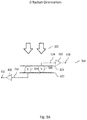
- Figure 2A illustrates an exemplary pair of radiation detectors at a 0 radian orientation, according to one implementation of the current subject matter.
- Figure 2B illustrates the exemplary pair of radiation detectors from FIG. 2A at a ⁇ radian orientation, according to one implementation of the current subject matter.
- Figure 3A illustrates an alternative implementation of an exemplary pair of radiation detectors at a 0 radian orientation.
- Figure 3B illustrates an alternative implementation of the exemplary pair of radiation detectors from FIG. 3A at a ⁇ radian orientation.
- An array of detectors consistent with implementations of the present disclosure may be utilized with any radiation delivery system, including but not limited to, radiation system. 100 shown in FIG. 1 .
- the radiation detectors can be mounted in odd and/or even orientations.
- reference to "odd” and “even” is an arbitrary label that is intended to merely distinguish between different orientations of the pairs of detectors relative to incident radiation.
- an "even” orientation refers to a radiation detector oriented to receive radiation head-on or in an approximately 180 degree arc "in front" of the detector.
- an "odd” orientation refers to a radiation detector oriented to receive radiation predominantly from the other side (or “rear”) of the radiation detector.
- the detectors can generate specific responses to radiation that is incident upon the detectors.
- the responses can be different based on the direction of the radiation, which can include, for example, incidence angles of 0 and/or ⁇ radians as shown in the figures.
- the differences between responses can be measured using known angles of incidence, which can be determined using a calibrated inclinometer and/or any other means.
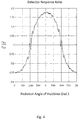
- a response plot being indicative of a ratio of radiation detector responses, can be generated (an exemplary response plot illustrating detector response ratios versus angles of incidence to a pair of detectors is shown in FIG. 4 ). Based on the response plot, a determination of a gantry angle 122, as the gantry rotates, can be made.
- arrays 250 can be planar (or flat), where neighboring detectors can be oriented ⁇ radians with regard to one another (as shown in FIGS. 2A and 2B or 3A and 3B) .
- Such arrays 250 can have a mathematical parity in detector orientation that can switch between odd and even orientations between neighboring detectors, with odd or even arbitrarily defined in accordance with orientation of the detector, as described above.
- an exemplary array 250 can be arranged in a 0 radians orientation with respect to incident beam 201 (as opposed to the ⁇ radians orientation of the array shown in FIG. 2B ).
- the arrangements shown in FIGS. 2A and 2B are for illustrative purposes only and are not intended to limit the current subject matter.
- the shown orientations can be based on an angle of incidence of a radiation beam.
- An array 250 can include a substrate (e.g., a printed circuit board (“PCB”)) 220 that can be used to mount irradiating detectors 204 and 206, where detector 204 is mounted in an even orientation and detector 206 is mounted in an odd orientation with respect to the incident beam 202.
- PCB printed circuit board
- Detectors 204, 206 can be communicatively coupled to measuring electronics 208, 210, respectively. Upon detecting radiation, detector 204 can generate signal 212 and pass it along to measuring electronics 208, which can generate measurement data 216. Similarly, upon detecting radiation, detector 206 can generate signal 214 and pass it along to measuring electronics 210, which can generate measurement data 218.
- the exemplary array 250 can be arranged in ⁇ radians orientation (as opposed to the 0 radians orientation of the array shown in FIG. 2a ) with respect to incident beam 201.
- Detector 204 and can now be positioned in an odd orientation and detector 206 is positioned in an even orientation with respect to the incident beam 201.
- detector 204 can generate signal 211 and pass it along to the measuring electronics 208, which can generate measurement data 215.
- the detector 206 can generate signal 213 and pass it along to the measuring electronics 210, which can generate measurement data 217.
- FIGS. 3A and 3B illustrate alternate implementations, where detectors can be mounted on separate substrates or PCBs.
- exemplary array 350 can be arranged in 0 radians orientation (as opposed to ⁇ radians orientation of the array shown in FIG. 3B ).
- FIGS. 3A and 3B illustrate alternate implementations, where detectors can be mounted on separate substrates or PCBs.
- exemplary array 350 can be arranged in 0 radians orientation (as opposed to ⁇ radians orientation of the array shown in FIG. 3B ).
- FIGS. 3A and 3B illustrate alternate implementations, where detectors can be mounted on separate substrates or PCBs.
- exemplary array 350 can be arranged in 0 radians orientation (as opposed to ⁇ radians orientation of the array shown in FIG. 3B ).
- FIGS. 3A and 3B illustrate alternate implementations, where detectors can be mounted on separate substrates or PCBs.
- exemplary array 350 can be arranged in 0 radians orientation (a
- Array 350 can include a substrate (e.g., PCB) 320 that can be used to mount irradiating detector 306 and another substrate or PCB 322 that can be used to mount detector 304. As shown in FIG. 3A , substrates 320 and 322 can be arranged substantially parallel to one another, however, as can be understood, substrates 320, 322 can be arranged in any other desired fashion.
- Detector 304 can be mounted in an even orientation and detector 306 can be mounted in an odd orientation with respect to the incident beam 302.
- Detectors 304, 306 can be communicatively coupled to measuring electronics 308, 310, respectively.
- detector 304 Upon detecting radiation, detector 304 can generate signal 312 and pass it along to measuring electronics 308, which can generate measurement data 316.
- detector 306 can generate signal 314 and pass it along to the measuring electronics 310, which can generate measurement data 318.
- exemplary array 350 can be arranged in a ⁇ radian orientation (as opposed to 0 radians orientation of the array shown in FIG. 3A ).
- Detector 304 can be mounted in an odd orientation and the detector 306 can be mounted in an even orientation with respect to incident beam 301.
- detector 304 Upon detecting radiation, detector 304 can generate signal 311 and pass it along to the measuring electronics 308, which can generate measurement data 315.
- detector 306 can generate signal 313 and pass it along to measuring electronics 310, which can generate measurement data 317.
- two array normalizations calculations can be performed.
- One array normalization calculation (otherwise known as an array calibration) can be performed using radiation incident normal to the array in one of the two possible normal orientations (e.g., FIGS. 2A or 3A ), and the other normalization calculation can be performed using radiation incident at the second orientation normal to the array, rotated ⁇ radians from the first orientation (e.g., FIGS. 2B or 3B , respectively).
- the array normalization calculations can generate a correction matrix, whereby all detectors can have an invariant sensitivity in that orientation to the radiation (i.e., a function, a quantity, and/or a property that remains unchanged when a specified transformation is applied).
- the quantity can be the measured charge from incident radiation after the transformation (correction factor) has been applied.
- array normalizations might not be necessary if nominal array sensitivity factors are known.
- radiation dose distributions can be determined.
- application of two normalization arrays on a single measurement of a beam of radiation at any angle of incidence to the array can result in two possible dose distributions.
- These two dose distributions can correct for the even/odd parity orientations of the neighboring detectors.
- Two additional dose distributions can be determined by matching parity orientations in the normalization arrays and applying these equal parity arrays to the measurement array that has a mixed parity. The result can be a dose distribution that can have a portion of the detectors corrected with an even parity and the other portion of detectors corrected with an odd parity.
- a dose difference between the neighboring detectors can be determined.
- the dose difference can be based on a detector's proximity to its neighbor detectors being in a low dose gradient region of the radiation field.
- the determined dose difference can be used to obtain information on the beam incident angle.
- the even orientation of detector X 204 can have an even normalization factor, while that same detector X (i.e., detector 204 shown in FIG. 2B ) can have an odd normalization factor when it is oriented odd during an array normalization measurement.
- detector X 204 can have two possible results after applying the array factor.
- the odd orientation detector Y 206 can have an odd normalization factor, while it can have an even normalization factor when oriented even.
- the results r Xe and r Yo can have substantially similar or same values. Similarly, the results r Xo and r Ye can also have substantially similar or same values. However, the results r Xe and r Ye are not equivalent because while parities of their normalization factors match, their orientation parities in the beam do not. Similarly, the results r Xo and r Yo are not equivalent for the same reasons.
- Figure 4 illustrates an exemplary experimental detector response ratio plot as a function of gantry angle, according to an implementation of the current subject matter.
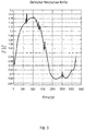
- Figure 5 illustrates an exemplary experimental detector response ratio of plot as a function of beam delivery time during rotation of the gantry according to an implementation of the current subject matter.
- Plot 400 illustrates an exemplary transfer function from a dose difference (i.e., a detector response ratio) to gantry angle 122.
- Plot 500 illustrates a ratio r Xe / r Ye as a function of beam delivery time as the gantry rotates.
- FIG. 4 and FIG. 5 are based on r Xe lr Ye , the ratio r Xo / r Yo can be used as well.
- a gantry angle 122 can be determined using the transfer function shown in FIG. 4 .
- System 600 can include one or more of a processor 610, a memory 620, a storage device 630, and an input/output device 640. Each of components 610, 620, 630 and 640 can be interconnected using system bus 650.
- Processor 610 can be configured to process instructions for execution within the system 600. In some implementations, processor 610 can be a single-threaded processor. In alternate implementations, processor 6 10 can be a multi-threaded processor. Processor 610 can be further configured to process instructions stored in memory 620 or on storage device 630, including receiving or sending information through the input/output device 640.
- Memory 620 can store information within system 600.
- memory 620 can be a computer-readable medium. In alternate implementations, memory 620 can be a volatile memory unit. In yet some implementations, memory 620 can be a non-volatile memory unit.
- Storage device 630 can be capable of providing mass storage for system 600. In some implementations, storage device 630 can be a computer-readable medium. In alternate implementations, storage device 630 can be a floppy disk device, a hard disk device, an optical disk device, a tape device, non-volatile solid-state memory, or any other type of storage device.
- the input/output device 640 can be configured to provide input/output operations for system 600. In some implementations, input/output device 640 can include a keyboard and/or pointing device. In alternate implementations, input/output device 640 can include a display unit for displaying graphical user interfaces.
- control system 114 can be used to determine gantry angle 122 utilizing the systems and methods described herein.
- computer hardware, software and devices used to determine gantry angle 122 can be separate from control system 114.
- both control system 114 and separate hardware, software and/or devices may be used together to determine gantry angle 122.
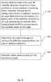
- Figure 7 illustrates an exemplary process 700 for determining a beam angle direction, according to some implementations of the current subject matter.
- at least one detector array normalization can be determined. The determination can be made using an array of neighboring detectors in a radiation system, where the detectors can be arranged in odd/even orientation with regard to an incident beam, where orientation of the detectors with respect to the incident beam can be rotated ⁇ radians to obtain different results. The determination can include calculation of array normalization or using known parameters.
- a correction matrix based on the array normalizations, can be generated.
- the correction matrix can be applied to at least one measurement of a beam of radiation at any angle of incidence to determine at least one radiation dose distribution.
- a radiation dose difference for at least two detectors in the detector array can be determined.
- beam incident angle information can be determined using the radiation dose difference, as determined at 708.
- a method of determining gantry angle 122 can include performing at least one of the following: measuring a radiation response ratio between neighboring detectors versus gantry rotation angles, measuring an angular dependence of each detector versus gantry rotational angles, calculating a dose gradient for each beam angle during radiation measurement, calculating neighboring detector ratios in the low dose gradient region (e.g., an average for multiple ratios in a region), using the determined detector ratio to match a predefined detector ratio versus gantry angle curve and determine gantry angle 122, and using determined gantry angle 122 to match an angular response to gantry angle 122 for each detector while applying a correction factor to the angular response.
- a method implemented by a programmable processor, and/or embedded as instructions in a non-transient, computer-readabte medium, can include receiving detector data from a pair of radiation detectors.
- the pair of radiation detectors can be located at a fixed position to receive radiation originating from a radiation therapy device 102 configured to deliver a radiation beam 112 at an angle 122 determined by orientation of a gantry 104.
- Each of the radiation detectors in the pair can generate the detector data based at least on differing responses to radiation beam 112 at the angle 122.
- the method or instructions can also include determining the angle 122 of the gantry 104 utilizing the differing responses from the pair of radiation detectors. A dose may then be calculated based at least on determined angle 122.
- One or more aspects or features of the subject matter described herein can be realized in digital electronic circuitry, integrated circuitry, specially designed application specific integrated circuits (ASICs), field programmable gate arrays (FPGAs) computer hardware, firmware, software, and/or combinations thereof.
- ASICs application specific integrated circuits
- FPGAs field programmable gate arrays
- These various aspects or features can include implementation in one or more computer programs that are executable and/or interpretable on a programmable system including at least one programmable processor, which can be special or general purpose, coupled to receive data and instructions from, and to transmit data and instructions to, a storage system, at least one input device, and at least one output device.
- the programmable system or computing system may include clients and servers.
- a client and server are generally remote from each other and typically interact through a communication network. The relationship of client and server arises by virtue of computer programs running on the respective computers and having a client-server relationship to each other.
- machine-readable signal refers to any signal used to provide machine instructions and/or data to a programmable processor.
- the machine-readable medium can store such machine instructions non-transkorily, such as for example as would a non-transient solid-state memory or a magnetic hard drive or any equivalent storage medium.
- the machine-readable medium can alternatively or additionally store such machine instructions in a transient manner, such as for example as would a processor cache or other random access memory associated with one or more physical processor cores.
- one or more aspects or features of the subject matter described herein can be implemented on a computer having a display device, such as for example a cathode ray tube (CRT) or a liquid crystal display (LCD) or a light emitting diode (LED) monitor for displaying information to the user and a keyboard and a pointing device, such as for example a mouse or a trackball, by which the user may provide input to the computer.
- a display device such as for example a cathode ray tube (CRT) or a liquid crystal display (LCD) or a light emitting diode (LED) monitor for displaying information to the user
- LCD liquid crystal display
- LED light emitting diode
- a keyboard and a pointing device such as for example a mouse or a trackball
- feedback provided to the user can be any form of sensory feedback, such as for example visual feedback, auditory feedback, or tactile feedback; and input from the user may be received in any form, including, but not limited to, acoustic, speech, or tactile input.
- Other possible input devices include, but are not limited to, touch screens or other touch-sensitive devices such as single or multi-point resistive or capacitive trackpads, voice recognition hardware and software, optical scanners, optical pointers, digital image capture devices and associated interpretation software, and the like.
- phrases such as "at least one of” or “one or more of” may occur followed by a conjunctive list of elements or features.
- the term “and/or” may also occur in a list of two or more elements or features. Unless otherwise implicitly or explicitly contradicted by the context in which it used, such a phrase is intended to mean any of the listed elements or features individually or any of the recited elements or features in combination with any of the other recited elements or features.
- the phrases “at least one of A and B;” “one or more of A and B;” and “A and/or B” are each intended to mean "A alone, B alone, or A and B together.”
- a similar interpretation is also intended for lists including three or more items.
- phrases “at least one of A, B, and C;” “one or more of A, B, and C;” and “A, B, and/or C” are each intended to mean “A alone, B alone, C alone, A and B together, A and C together, B and C together, or A and B and C together.”
- Use of the term “based on,” above and in the claims is intended to mean, “based at least in part on,” such that an unrecited feature or element is also permissible.
Landscapes
- Health & Medical Sciences (AREA)
- Engineering & Computer Science (AREA)
- Biomedical Technology (AREA)
- Pathology (AREA)
- Nuclear Medicine, Radiotherapy & Molecular Imaging (AREA)
- Radiology & Medical Imaging (AREA)
- Life Sciences & Earth Sciences (AREA)
- Animal Behavior & Ethology (AREA)
- General Health & Medical Sciences (AREA)
- Public Health (AREA)
- Veterinary Medicine (AREA)
- Radiation-Therapy Devices (AREA)
Description
- Radiation therapy is used to treat cancerous tumors with ionizing radiation that kills the affected cancer cells. External beam radiotherapy can be used to deliver ionizing radiation. In such therapy, a patient is placed on a couch and a radiotherapy beam generator is positioned to direct the ionizing radiation at the patient's tumor.
- A linear accelerator ("LINAC") is typically used for the purpose of delivering external beam radiation treatments to patients. A LINAC can deliver high-energy x-ray beams to the region of the target tissue, where the x-ray is sufficiently focused to destroy the target cells (e.g., tumor cells, abnormal cells, etc.), while avoiding the surrounding normal tissue. Document
EP 2 186 542 relates to a method and device for determining the position of a radiation isocenter of a particle beam delivery system. The particle beam delivery system is configured for delivering a radiation beam along one or a multiple number of delivery directions (D1, D2, .... , Di, ... , Dn) in a treatment room. The position of the radiation isocenter is being determined for each delivery direction. The device of invention comprises two beam monitors arranged in a face to face relationship at a given distance from each other. Both beam monitors are measuring a radiation field in two dimensions. Processing means are provided to calculate the position of the radiation isocenter with respect to a reference 3D coordinate system. - The invention is defined in the following claims; other embodiments and methods are disclosed for illustrative purposes only.
- A system is disclosed that includes a radiation therapy device with a gantry. The radiation therapy device is configured to deliver a radiation beam at an angle determined by orientation of the gantry. Also, a pair of radiation detectors are located at a fixed position to receive radiation originating from the radiation beam. Each of the radiation detectors in the pair generate differing responses to the radiation beam at the angle. The system further includes computer hardware configured to perform operations that determine the angle of the gantry utilizing the differing responses from the pair of radiation detectors.
- In some variations one or more of the following features can optionally be included in any feasible combination. The computer hardware can be further configured to display the determined angle, to compare the determined angle to a planned angle, or to use the determined angle in a dose calculation.
- In other variations, the fixed position of the pair of radiation detectors can be within the radiation beam. The fixed position of the pair of radiation detectors can be outside of the radiation beam and the pair of radiation detectors can detect scattered radiation. The pair of radiation detectors can be mounted on a single substrate or on different substrates. The radiation detectors in the pair can be oriented in opposite directions. The radiation detectors can generate differing responses due to their orientation, due to the detectors being of different types, or due to the placement of radiation absorbing material.
- In yet other variations, the detectors can be close together or have a separation between the pair of radiation detectors of approximately 2.5 mm.
- In some variations, the system can include multiple pairs of radiation detectors, and the determining can be based on the differing responses of multiple close together pairs of radiation detectors. The system can also include a flat array of radiation detectors including the pair of radiation detectors.
- In an interrelated aspect, a system is disclosed that includes a pair of radiation detectors located at a fixed position to receive radiation originating from a radiation therapy device configured to deliver a radiation beam at an angle determined by orientation of a gantry. Each of the radiation detectors in the pair generate differing responses to the radiation beam at the angle. Computer hardware is configured to perform operations that include determining the angle of the gantry utilizing the differing responses from the pair of radiation detectors.
- In another interrelated aspect, a computer program product is disclosed that includes a non-transient, machine-readable medium storing instructions which, when executed by at least one programmable processor, cause the at least one programmable processor to perform operations that include receiving detector data from a pair of radiation detectors located at a fixed position to receive radiation originating from a radiation therapy device configured to deliver a radiation beam at an angle determined by orientation of a gantry. Each of the radiation detectors in the pair generate the detector data based at least on differing responses to the radiation beam at the angle. The operations also include determining the angle of the gantry utilizing the differing responses from the pair of radiation detectors and calculating a dose based at least on the determined angle.
- Implementations of the current subject matter can include, but are not limited to, methods consistent with the descriptions provided herein as well as articles that comprise a tangibly embodied machine-readable medium operable to cause one or more machines (e.g., computers, etc.) to result in operations implementing one or more of the described features. Similarly, computer systems are also contemplated that may include one or more processors and one or more memories coupled to the one or more processors. A memory, which can include a computer-readable storage medium, may include, encode, store, or the like, one or more programs that cause one or more processors to perform one or more of the operations described herein. Computer implemented methods consistent with one or more implementations of the current subject matter can be implemented by one or more data processors residing in a single computing system or across multiple computing systems. Such multiple computing systems can be connected and can exchange data and/or commands or other instructions or the like via one or more connections, including but not limited to a connection over a network (e.g., the internet, a wireless wide area network, a local area network, a wide area network, a wired network, or the like), via a direct connection between one or more of the multiple computing systems, etc.
- The details of one or more variations of the subject matter described herein are set forth in the accompanying drawings and the description below. Other features and advantages of the subject matter described herein will be apparent from the description and drawings, and from the claims. While certain features of the currently disclosed subject matter are described for illustrative purposes in relation to particular implementations, it should be readily understood that such features are not intended to be limiting. The claims that follow this disclosure are intended to define the scope of the protected subject matter.
- The accompanying drawings, which are incorporated in and constitute a part of this specification, show certain aspects of the subject matter disclosed herein and, together with the description, help explain some of the principles associated with the disclosed implementations. In the drawings,
-
Figure 1 is a simplified diagram illustrating a radiation therapy system, according to some implementations of the current subject matter. -
Figure 2A illustrates an exemplary pair of radiation detectors at a 0 radian orientation, according to some implementations of the current subject matter. -
Figure 2B illustrates the exemplary pair of radiation detectors fromFIG. 2A at a π radian orientation, according to some implementations of the current subject matter. -
Figure 3A illustrates an alternative implementation of an exemplary pair of radiation detectors at a 0 radian orientation, according to some implementations of the current subject matter. -
Figure 3B illustrates an alternative implementation of the exemplary pair of radiation detectors fromFIG. 3A at a π radian orientation, according to some implementations of the current subject matter. -
Figure 4 illustrates an exemplary experimental detector response ratio plot as a function of gantry angle, according some implementations of the current subject matter. -
Figure 5 illustrates an exemplary experimental detector response ratio of plot as a function of beam delivery time during rotation of the gantry according to some implementations of the current subject matter. -
Figure 6 illustrates an exemplary system according to some implementations of the current subject matter. -
Figure 7 illustrates an exemplary process according to some implementations of the current subject matter. -
Figure 8 illustrates another exemplary process according to some implementations of the current subject matter. - During radiation therapy, a patient can be positioned on a patient couch and a radiation beam can be delivered to a target tissue of patient. The target tissue can be previously identified through use of various scanning technologies such as magnetic resonance imaging or computed tomography. The positioning of the patient can also be predetermined so that the location of the delivery of the radiation beam is accurate.
- To deliver a proper radiation treatment to a patient, a radiation treatment plan can be developed. The plan can include, for example, information about radiation delivery, delivery log information, time, dose information, treatment beam shape or energy, orientation or angle of the gantry, collimator leaf positions, patient anatomy orientation with respect to the treatment beam (e.g., CT images), any other measurements, and/or any other data.
- One of the attributes of clinical radiotherapy ("RT") is an ability to change the LINAC's gantry angle over the course of a treatment fraction. The fraction can include one or more (e.g., seven) fields of radiation. The gantry angle can be used to determine the radiation beam entrance angle to the patient, to ensure that treatment of target tissue (e.g., tumor, abnormal, etc.) takes places at an intersection of the fields delivered during the fraction, while healthy tissue is substantially unaffected. A fraction can be characterized by stationary angles (e.g., blocked fields or intensity-modulated radiation therapy ("IMRT")) and/or continuously changing gantry angles while the field shape is modulated to conform to the target volume (after referred to as volumetric arc therapy ("VMAT")).
-
Figure 1 illustrates anexemplary radiation system 100 according to some implementations of the current subject matter.Radiation system 100 can includeradiation therapy device 102,gantry 104,beam collimator 106, radiation detector (or a radiation detector array) 108,patient couch 110, andcontrol system 114. - The
gantry 104 can includeradiation therapy device 102 that can have a radiation source such as a LINAC, Cobalt 60 source, etc., that can direct radiation towardpatient 120 by way ofradiation beam 112.Radiation beam 112 can include scanning beams, where a small beamlet can be scanned over the area that is required to be treated.Radiation beam 112 may also be shaped bybeam collimator 106 prior to application topatient 120. Thoughradiation beam 112 is illustrated as a line inFIG. 1 , it is understood that this is only a simplification and thatradiation beam 112 has a two dimensional cross-section. The cross-section can be determined at least by shaping withbeam collimator 106. - In some implementations,
gantry 104 can rotate aboutpatient 120. The angle of the gantry 104 (and radiation beam 112) is shown inFIG. 1 asgantry angle 122.Gantry 104 can rotate 360° aroundpatient 120, or have a more limited range of rotation. It is contemplated thatgantry 104 can rotate to any desired angle as specified by an operator, a radiation treatment plan,control system 114, or the like, within the limits ofradiation system 100. The above exemplary rotation ranges and the simplified illustration ofgantry angle 122 inFIG. 1 are not intended to be limiting except as explicitly described herein. - Operation of
radiation system 100 can be controlled usingcontrol system 114, which can include processors, computers, hardware, computer programs, and any combination thereof.Control system 114 can be used to determine howradiation beam 112 can be delivered to the patient, the rotation ofgantry 104, the positioning ofpatient 120, as well as other parameters of the treatment process.Control system 114 can also be used to monitorpatient 120 during the treatment (e.g., a treatment fraction) and/or change treatment parameters, if so required.Control system 114 may be used to perform quality assurance ("QA") to ensure that accurate radiation treatment is delivered.Radiation system 100 can be designed to deliver radiation therapy to any part of the human body, where only a portion of the human body can be placed in the vicinity of theradiation system 100. -
Radiation therapy device 102 can be periodically tested to verify its ability to deliver radiation fields defined by a standardized QA protocol, as well as its ability to deliver radiation fields defined by a treatment planning system ("TPS") for a specific patient treatment. As shown inFIG. 1 ,radiation system 100 can includeradiation therapy device 102 withgantry 104.Radiation therapy device 102 can be configured to deliverradiation beam 112 at an angle determined by orientation ofgantry 104. As part of the radiation system QA,gantry angle 122 can be verified to ensure accurate radiation delivery. - According to certain aspects of the present disclosure, radiation detectors can be utilized to provide an independent measurement of
gantry angle 122 by analyzing specific radiation detector responses due to received radiation. In some implementations, a pair of radiation detectors can be located at a fixed position to receive radiation originating fromradiation beam 112.Radiation detector 108 can include one or more of pairs of radiation detectors, or, alternatively, an odd number of detectors. In one implementation, radiation detectors can be placed in the path ofradiation beam 112, either before or after apatient 120. In another implementation, radiation detectors may be utilized in a quality assurance procedure prior to a treatment, for example, detectors may be placed within a phantom or directly withinradiation beam 112 with no other materials. - As used herein, reference to the pair of radiation detectors being "within the radiation beam" is understood to mean that the radiation detectors directly receive the radiation beam, as opposed to only receiving scattered radiation. For example, the radiation detectors may be between patient 120 (or phantom) and
radiation therapy device 102, or on the other side of patient 120 (or phantom) but still in a direct line with the beam ofradiation therapy device 102. - In another implementation, the pair of radiation detectors can be outside of
radiation beam 112 and detect scattered radiation. For example, the pair of radiation detectors can be a part ofradiation detector 108 that is not directly in the path ofradiation beam 112 or can be mounted elsewhere in the treatment room (e.g., on the walls, ceiling, etc.). - The pair of radiation detectors can be disposed anywhere that the direct radiation or the scattered radiation can be intercepted. In some implementations, the pair of radiation detectors can be close together such that adjacent radiation detectors effectively receive the same amount of radiation (neglecting any intervening materials). For example, adjacent radiation detectors (in the pair or otherwise) can be in contact, or separated by 1 mm, 2 mm, 2.5 mm, less than a centimeter, 1-5 cm, etc. The separation between adjacent radiation detectors can be based in part on the radiation field size either at the patient, at the phantom, or at the detector location. In some implementations, the separation can be proportional to the smallest field size dictated by the radiation treatment plan. In implementations of the current subject matter where multiple pairs of radiation detectors are utilized in the determination of
gantry angle 122, the multiple pairs may be similarly configured to be close together. - In other implementations, the pair of radiation detectors can be part of an array or multiple pairs of radiation detectors. Determination of the
gantry angle 122 can be based on one or more close pairs of radiation detectors. - In other implementations, there can be a flat array of radiation detectors that include the pair of radiation detectors. The flat array can be mounted at the
radiation detector 108, on the walls, ceiling, etc. - As used herein, the term "response" refers to a raw or processed output of the pair of radiation detectors (or of radiation detector 108) that is generated when radiation is intercepted by the detector. For example a response can be an electrical signal generated by each detector of the pair of radiation detectors, or a scaled/normalized/processed representation of such. Also as used herein, the term "signal" refers to a raw detector output, for example a voltage, current, etc.
- Each of the radiation detectors in the pair can be configured to generate differing responses to the radiation beam depending on the angle of
gantry 104. For example, because of the angular sensitivity of certain detectors, if they are oriented differently, the radiation intercepted by one radiation detector can generate a first response at aparticular gantry angle 122 and the radiation intercepted by the other detector in the pair can generate a second (and different) response. The difference in (or alternatively the ratio of) the two responses can then be a function ofgantry angle 122. Whengantry angle 122 changes, the differing responses (or response ratio) can change accordingly. Conversely, if the radiation emitted fromradiation therapy device 102 changes due to, for example, only a change in the beam output due to the opening or closing ofbeam collimator 106 or a change in the beam energy, then the difference in responses can remain unchanged becausegantry angle 122 has not changed. - With a calibrated pair of radiation detectors,
gantry angle 122 can be calculated. To calibrate the pair of radiation detectors,gantry 104 can be rotated to different gantry angles and the response of the pair of radiation detectors can be measured at eachgantry angle 122. The calibration can be stored as a data file on a connected computing system and accessed as part of a QA process or as part of radiation treatment delivery. - A pair of radiation detectors can generate differing responses for different reasons, depending on various implementations of the present disclosure. For example, the differing responses can be due to their orientation, due to the pair of radiation detectors being of different types, or due to the placement of radiation absorbing material. When the response of a single radiation detector is a function of angle (e.g., the radiation detector generates a stronger signal when the radiation strikes it head-on as opposed to striking from the side or the rear), the differing responses (to radiation striking the pair of radiation detectors at the same angle) can be due to the radiation detectors in the pair being oriented in different directions or opposite directions. Examples of such orientations are shown in
FIGs. 2A ,2B ,3A , and3B . In other implementations, when the radiation detectors are different types of radiation detectors, they can have a different response as a function of incident radiation angle even if they are mounted in the same orientation. For example, a first type of radiation detector can have a factor of two increase in signal whengantry angle 122 changes from 0 to 30° and a second type of radiation detector can have a factor of three increase for the same change ingantry angle 122. For each type of radiation detector, a known response as a function of incident radiation angle can allowgantry angle 122 to be determined. In yet another implementation, intervening material (e.g., radiation absorbing or scattering material such as lead) can also provide a difference in response between the pair of radiation detectors. - Computer hardware can be configured to perform operations that determine
gantry angle 122 utilizing the differing responses from the pair of radiation detectors. This can include each of the radiation detectors in the pair generating detector data based at least on differing responses to the radiation beam atgantry angle 122. The computer hardware can also calculate a delivered dose based partially on the determined angle. Also, oncegantry angle 122 is determined by any of the implementations described herein, the computer hardware can display thedetermined gantry angle 122, can compare the determined angle to a planned angle, or can use the determined angle in a dose calculation. In some implementations, the system responsible for determininggantry angle 122 can include the pair of radiation detectors and the computer hardware separate from theradiation therapy device 102. - In some implementations, the QA device can include one or more lines of detectors and/or an array of detectors that can be used to determine
gantry angle 122. The array of radiation detectors can include any number of pairs of radiation detectors. As discussed above with reference to a single pair of radiation detectors, in some exemplary implementations, line(s) or planar array(s) of detectors in a QA device can have a significant directional response due to their asymmetric construction. In some implementations, the current subject matter provides for a two-dimensional planar array of detectors that can be used to account for the directional response of detectors. The two-dimensional planar array of detectors can enable determination of gantry beam angle based on its own radiation measurement data. While the present disclosure describes embodiments utilizing pair(s) of detectors, it is contemplated that other groupings of detectors greater than one may be similarly utilized to determinegantry angle 122. -
Figure 2A illustrates an exemplary pair of radiation detectors at a 0 radian orientation, according to one implementation of the current subject matter.Figure 2B illustrates the exemplary pair of radiation detectors fromFIG. 2A at a π radian orientation, according to one implementation of the current subject matter.Figure 3A illustrates an alternative implementation of an exemplary pair of radiation detectors at a 0 radian orientation.Figure 3B illustrates an alternative implementation of the exemplary pair of radiation detectors fromFIG. 3A at a π radian orientation. - An array of detectors consistent with implementations of the present disclosure may be utilized with any radiation delivery system, including but not limited to, radiation system. 100 shown in
FIG. 1 . As shown inFIGS. 2A ,2B ,3A , and3B , (showing only a single pair of radiation detectors, which may be included in an array 250) the radiation detectors can be mounted in odd and/or even orientations. As used herein, reference to "odd" and "even" is an arbitrary label that is intended to merely distinguish between different orientations of the pairs of detectors relative to incident radiation. For example, an "even" orientation refers to a radiation detector oriented to receive radiation head-on or in an approximately 180 degree arc "in front" of the detector. In contrast, an "odd" orientation refers to a radiation detector oriented to receive radiation predominantly from the other side (or "rear") of the radiation detector. - The detectors can generate specific responses to radiation that is incident upon the detectors. The responses can be different based on the direction of the radiation, which can include, for example, incidence angles of 0 and/or π radians as shown in the figures. The differences between responses can be measured using known angles of incidence, which can be determined using a calibrated inclinometer and/or any other means. Using the detectors' responses data, a response plot, being indicative of a ratio of radiation detector responses, can be generated (an exemplary response plot illustrating detector response ratios versus angles of incidence to a pair of detectors is shown in
FIG. 4 ). Based on the response plot, a determination of agantry angle 122, as the gantry rotates, can be made. Thus, using the exemplary detector array systems having odd-even orientations of detector(s), as shown inFIGS. 2A and2B or3A and3B , an angle of incidence for a radiation detector can be determined based on the determined and/or known directional response of its neighbor detector, thereby allowing determination of agantry angle 122. In some implementations,arrays 250 can be planar (or flat), where neighboring detectors can be oriented π radians with regard to one another (as shown inFIGS. 2A and2B or3A and3B) .Such arrays 250 can have a mathematical parity in detector orientation that can switch between odd and even orientations between neighboring detectors, with odd or even arbitrarily defined in accordance with orientation of the detector, as described above. - Referring to
FIG. 2A , anexemplary array 250 can be arranged in a 0 radians orientation with respect to incident beam 201 (as opposed to the π radians orientation of the array shown inFIG. 2B ). As can be understood, the arrangements shown inFIGS. 2A and2B are for illustrative purposes only and are not intended to limit the current subject matter. The shown orientations can be based on an angle of incidence of a radiation beam. Anarray 250 can include a substrate (e.g., a printed circuit board ("PCB")) 220 that can be used to mount irradiatingdetectors detector 204 is mounted in an even orientation anddetector 206 is mounted in an odd orientation with respect to theincident beam 202.Detectors electronics detector 204 can generate signal 212 and pass it along to measuringelectronics 208, which can generatemeasurement data 216. Similarly, upon detecting radiation,detector 206 can generate signal 214 and pass it along to measuringelectronics 210, which can generatemeasurement data 218. - Referring to
FIG. 2B , theexemplary array 250 can be arranged in π radians orientation (as opposed to the 0 radians orientation of the array shown inFIG. 2a ) with respect toincident beam 201.Detector 204 and can now be positioned in an odd orientation anddetector 206 is positioned in an even orientation with respect to theincident beam 201. Upon detecting radiation,detector 204 can generate signal 211 and pass it along to the measuringelectronics 208, which can generatemeasurement data 215. Similarly, upon detecting radiation, thedetector 206 can generate signal 213 and pass it along to the measuringelectronics 210, which can generatemeasurement data 217. -
FIGS. 3A and3B illustrate alternate implementations, where detectors can be mounted on separate substrates or PCBs. Referring toFIG. 3A ,exemplary array 350 can be arranged in 0 radians orientation (as opposed to π radians orientation of the array shown inFIG. 3B ). As can be understood, similar toFIGS. 2A and2B , the arrangements shown inFIGS. 3A and3B are provided here for illustrative purposes only and are not intended to limit the present disclosure. The shown orientations can be based on an angle of incidence of a radiation beam.Array 350 can include a substrate (e.g., PCB) 320 that can be used to mount irradiatingdetector 306 and another substrate orPCB 322 that can be used to mountdetector 304. As shown inFIG. 3A ,substrates substrates Detector 304 can be mounted in an even orientation anddetector 306 can be mounted in an odd orientation with respect to theincident beam 302.Detectors electronics detector 304 can generate signal 312 and pass it along to measuringelectronics 308, which can generatemeasurement data 316. Similarly, upon detecting radiation,detector 306 can generate signal 314 and pass it along to the measuringelectronics 310, which can generatemeasurement data 318. - Referring to
FIG. 3B ,exemplary array 350 can be arranged in a π radian orientation (as opposed to 0 radians orientation of the array shown inFIG. 3A ).Detector 304 can be mounted in an odd orientation and thedetector 306 can be mounted in an even orientation with respect toincident beam 301. Upon detecting radiation,detector 304 can generate signal 311 and pass it along to the measuringelectronics 308, which can generatemeasurement data 315. Similarly, upon detecting radiation,detector 306 can generate signal 313 and pass it along to measuringelectronics 310, which can generatemeasurement data 317. - Using
arrays FIGS. 2A-B and/orFIGS. 3A-B , two array normalizations calculations can be performed. One array normalization calculation (otherwise known as an array calibration) can be performed using radiation incident normal to the array in one of the two possible normal orientations (e.g.,FIGS. 2A or3A ), and the other normalization calculation can be performed using radiation incident at the second orientation normal to the array, rotated π radians from the first orientation (e.g.,FIGS. 2B or3B , respectively). The array normalization calculations can generate a correction matrix, whereby all detectors can have an invariant sensitivity in that orientation to the radiation (i.e., a function, a quantity, and/or a property that remains unchanged when a specified transformation is applied). Here, the quantity can be the measured charge from incident radiation after the transformation (correction factor) has been applied. In some exemplary implementations, array normalizations might not be necessary if nominal array sensitivity factors are known. - Based on the determined array normalizations (whether calculated or known), radiation dose distributions can be determined. In particular, application of two normalization arrays on a single measurement of a beam of radiation at any angle of incidence to the array can result in two possible dose distributions. These two dose distributions can correct for the even/odd parity orientations of the neighboring detectors. Two additional dose distributions can be determined by matching parity orientations in the normalization arrays and applying these equal parity arrays to the measurement array that has a mixed parity. The result can be a dose distribution that can have a portion of the detectors corrected with an even parity and the other portion of detectors corrected with an odd parity.
- Based on the mixed parity dose calculation for the neighboring detectors, a dose difference between the neighboring detectors can be determined. The dose difference can be based on a detector's proximity to its neighbor detectors being in a low dose gradient region of the radiation field. The determined dose difference can be used to obtain information on the beam incident angle.
- For example, referring to
FIGS. 2A-B , the even orientation of detector X 204 (shown inFIG. 2A ) can have an even normalization factor, while that same detector X (i.e.,detector 204 shown inFIG. 2B ) can have an odd normalization factor when it is oriented odd during an array normalization measurement. For an arbitrary measurement,detector X 204 can have two possible results after applying the array factor. Similarly, the oddorientation detector Y 206 can have an odd normalization factor, while it can have an even normalization factor when oriented even. Hence, the results for the detectors X and Y, respectively, would be as follows:


wherein r is result, e is even parity, o is odd parity, m is a measured value, nf is a normalization factor. - Because detectors X 204 and
Y 206 are neighboring detectors in a region of zero and/or low dose gradient, the results rXe and rYo can have substantially similar or same values. Similarly, the results rXo and rYe can also have substantially similar or same values. However, the results rXe and rYe are not equivalent because while parities of their normalization factors match, their orientation parities in the beam do not. Similarly, the results rXo and rYo are not equivalent for the same reasons. -
Figure 4 illustrates an exemplary experimental detector response ratio plot as a function of gantry angle, according to an implementation of the current subject matter.Figure 5 illustrates an exemplary experimental detector response ratio of plot as a function of beam delivery time during rotation of the gantry according to an implementation of the current subject matter. Plot 400 illustrates an exemplary transfer function from a dose difference (i.e., a detector response ratio) togantry angle 122. Plot 500 illustrates a ratio rXe /rYe as a function of beam delivery time as the gantry rotates. ThoughFIG. 4 andFIG. 5 are based on rXelrYe, the ratio rXo /rYo can be used as well. Based on the response differences at different times during the gantry rotation (as shown inFIG. 5 ), agantry angle 122 can be determined using the transfer function shown inFIG. 4 . - In some implementations, the current subject matter can be configured to be implemented in
system 600, as shown inFIG. 6 .System 600 can include one or more of aprocessor 610, amemory 620, astorage device 630, and an input/output device 640. Each ofcomponents system bus 650.Processor 610 can be configured to process instructions for execution within thesystem 600. In some implementations,processor 610 can be a single-threaded processor. In alternate implementations, processor 6 10 can be a multi-threaded processor.Processor 610 can be further configured to process instructions stored inmemory 620 or onstorage device 630, including receiving or sending information through the input/output device 640.Memory 620 can store information withinsystem 600. In some implementations,memory 620 can be a computer-readable medium. In alternate implementations,memory 620 can be a volatile memory unit. In yet some implementations,memory 620 can be a non-volatile memory unit.Storage device 630 can be capable of providing mass storage forsystem 600. In some implementations,storage device 630 can be a computer-readable medium. In alternate implementations,storage device 630 can be a floppy disk device, a hard disk device, an optical disk device, a tape device, non-volatile solid-state memory, or any other type of storage device. The input/output device 640 can be configured to provide input/output operations forsystem 600. In some implementations, input/output device 640 can include a keyboard and/or pointing device. In alternate implementations, input/output device 640 can include a display unit for displaying graphical user interfaces. - In some implementations,
control system 114 can be used to determinegantry angle 122 utilizing the systems and methods described herein. In other implementations, computer hardware, software and devices used to determinegantry angle 122 can be separate fromcontrol system 114. In still other implementations, bothcontrol system 114 and separate hardware, software and/or devices may be used together to determinegantry angle 122. -
Figure 7 illustrates anexemplary process 700 for determining a beam angle direction, according to some implementations of the current subject matter. At 702, at least one detector array normalization can be determined. The determination can be made using an array of neighboring detectors in a radiation system, where the detectors can be arranged in odd/even orientation with regard to an incident beam, where orientation of the detectors with respect to the incident beam can be rotated π radians to obtain different results. The determination can include calculation of array normalization or using known parameters. At, 704, a correction matrix, based on the array normalizations, can be generated. At 706, the correction matrix can be applied to at least one measurement of a beam of radiation at any angle of incidence to determine at least one radiation dose distribution. At 708, using a mixed parity dose calculation, a radiation dose difference for at least two detectors in the detector array can be determined. At 710, beam incident angle information can be determined using the radiation dose difference, as determined at 708. - In other implementations, a method of determining
gantry angle 122 can include performing at least one of the following: measuring a radiation response ratio between neighboring detectors versus gantry rotation angles, measuring an angular dependence of each detector versus gantry rotational angles, calculating a dose gradient for each beam angle during radiation measurement, calculating neighboring detector ratios in the low dose gradient region (e.g., an average for multiple ratios in a region), using the determined detector ratio to match a predefined detector ratio versus gantry angle curve and determinegantry angle 122, and usingdetermined gantry angle 122 to match an angular response togantry angle 122 for each detector while applying a correction factor to the angular response. -
Figure 8 illustrates another exemplary process according to some implementations of the current subject matter. In another implementation, a method, implemented by a programmable processor, and/or embedded as instructions in a non-transient, computer-readabte medium, can include receiving detector data from a pair of radiation detectors. The pair of radiation detectors can be located at a fixed position to receive radiation originating from aradiation therapy device 102 configured to deliver aradiation beam 112 at anangle 122 determined by orientation of agantry 104. Each of the radiation detectors in the pair can generate the detector data based at least on differing responses toradiation beam 112 at theangle 122. The method or instructions can also include determining theangle 122 of thegantry 104 utilizing the differing responses from the pair of radiation detectors. A dose may then be calculated based at least ondetermined angle 122. - The present disclosure contemplates that the calculations disclosed in the embodiments herein may be performed in a number of ways, applying the same concepts taught herein, and that such calculations are equivalent to the embodiments disclosed.
- One or more aspects or features of the subject matter described herein can be realized in digital electronic circuitry, integrated circuitry, specially designed application specific integrated circuits (ASICs), field programmable gate arrays (FPGAs) computer hardware, firmware, software, and/or combinations thereof. These various aspects or features can include implementation in one or more computer programs that are executable and/or interpretable on a programmable system including at least one programmable processor, which can be special or general purpose, coupled to receive data and instructions from, and to transmit data and instructions to, a storage system, at least one input device, and at least one output device. The programmable system or computing system may include clients and servers. A client and server are generally remote from each other and typically interact through a communication network. The relationship of client and server arises by virtue of computer programs running on the respective computers and having a client-server relationship to each other.
- These computer programs, which can also be referred to programs, software, software applications, applications, components, or code, include machine instructions for a programmable processor, and can be implemented in a high-level procedural language, an object-oriented programming language, a functional programming language, a logical programming language, and/or in assembly/machine language. As used herein, the term "machine-readable medium" (or "computer readable medium") refers to any computer program product, apparatus and/or device, such as for example magnetic discs, optical disks, memory, and Programmable Logic Devices (PLDs), used to provide machine instructions and/or data to a programmable processor, including a machine-readable medium that receives machine instructions as a machine-readable signal. The term "machine-readable signal" (or "computer readable signal") refers to any signal used to provide machine instructions and/or data to a programmable processor. The machine-readable medium can store such machine instructions non-transkorily, such as for example as would a non-transient solid-state memory or a magnetic hard drive or any equivalent storage medium. The machine-readable medium can alternatively or additionally store such machine instructions in a transient manner, such as for example as would a processor cache or other random access memory associated with one or more physical processor cores.
- To provide for interaction with a user, one or more aspects or features of the subject matter described herein can be implemented on a computer having a display device, such as for example a cathode ray tube (CRT) or a liquid crystal display (LCD) or a light emitting diode (LED) monitor for displaying information to the user and a keyboard and a pointing device, such as for example a mouse or a trackball, by which the user may provide input to the computer. Other kinds of devices can be used to provide for interaction with a user as well. For example, feedback provided to the user can be any form of sensory feedback, such as for example visual feedback, auditory feedback, or tactile feedback; and input from the user may be received in any form, including, but not limited to, acoustic, speech, or tactile input. Other possible input devices include, but are not limited to, touch screens or other touch-sensitive devices such as single or multi-point resistive or capacitive trackpads, voice recognition hardware and software, optical scanners, optical pointers, digital image capture devices and associated interpretation software, and the like.
- In the descriptions above and in the claims, phrases such as "at least one of" or "one or more of" may occur followed by a conjunctive list of elements or features. The term "and/or" may also occur in a list of two or more elements or features. Unless otherwise implicitly or explicitly contradicted by the context in which it used, such a phrase is intended to mean any of the listed elements or features individually or any of the recited elements or features in combination with any of the other recited elements or features. For example, the phrases "at least one of A and B;" "one or more of A and B;" and "A and/or B" are each intended to mean "A alone, B alone, or A and B together." A similar interpretation is also intended for lists including three or more items. For example, the phrases "at least one of A, B, and C;" "one or more of A, B, and C;" and "A, B, and/or C" are each intended to mean "A alone, B alone, C alone, A and B together, A and C together, B and C together, or A and B and C together." Use of the term "based on," above and in the claims is intended to mean, "based at least in part on," such that an unrecited feature or element is also permissible.
Claims (14)
- A system comprising:a radiation therapy device with a gantry, the radiation therapy device configured to deliver a radiation beam at an angle determined by orientation of the gantry;the system being characterised by further encompassing:a pair of radiation detectors (108) located at a fixed position to receive radiation originating from the radiation beam, each of the radiation detectors in the pair generating differing responses to the radiation beam at the angle;computer hardware configured to determinethe angle of the gantry utilizing the differing responses from the pair of radiation detectors.
- The system of claim 1 wherein the computer hardware is further configured to display the determined angle, to compare the determined angle to a planned angle, or to use the determined angle in a dose calculation.
- The system of claim 1 wherein the fixed position of the pair of radiation detectors is during use, within the radiation beam.
- The system of claim 1 wherein the fixed position of the pair of radiation detectors is during use outside of the radiation beam and the pair of radiation detectors detect scattered radiation.
- The system of claim 1 wherein the pair of radiation detectors are mounted on a single substrate.
- The system of claim 1 wherein the pair of radiation detectors are mounted on different substrates.
- The system of claim 1 wherein the radiation detectors in the pair are oriented in opposite directions.
- The system of claim 1 wherein the radiation detectors generate differing responses due to their orientation.
- The system of claim 1 wherein the radiation detectors generate different responses due to the detectors being of different types.
- The system of claim 1 wherein the radiation detectors generate different responses due to the placement of radiation absorbing material.
- The system of claim 1 wherein the pair of radiation detectors have a separation of less than a centimeter.
- The system of claim 11 wherein the separation between the pair of radiation detectors is approximately 2.5 mm.
- The system of claim 1, further comprising multiple pairs of radiation detectors, the determining based on the differing responses of the multiple pairs of radiation detectors.
- The system of claim 1, further comprising a flat array of radiation detectors including the pair of radiation detectors.
Applications Claiming Priority (2)
| Application Number | Priority Date | Filing Date | Title |
|---|---|---|---|
| US201662367932P | 2016-07-28 | 2016-07-28 | |
| PCT/US2017/044472 WO2018023049A1 (en) | 2016-07-28 | 2017-07-28 | Beam angle direction determination |
Publications (2)
| Publication Number | Publication Date |
|---|---|
| EP3490672A1 EP3490672A1 (en) | 2019-06-05 |
| EP3490672B1 true EP3490672B1 (en) | 2021-03-03 |
Family
ID=59579932
Family Applications (1)
| Application Number | Title | Priority Date | Filing Date |
|---|---|---|---|
| EP17751188.8A Active EP3490672B1 (en) | 2016-07-28 | 2017-07-28 | Beam angle direction determination |
Country Status (3)
| Country | Link |
|---|---|
| US (1) | US10596394B2 (en) |
| EP (1) | EP3490672B1 (en) |
| WO (1) | WO2018023049A1 (en) |
Families Citing this family (6)
| Publication number | Priority date | Publication date | Assignee | Title |
|---|---|---|---|---|
| WO2018160763A1 (en) | 2017-02-28 | 2018-09-07 | Sun Nuclear Corporation | Radiation therapy treatment verification with electronic portal imaging device transit images |
| WO2021007459A1 (en) | 2019-07-10 | 2021-01-14 | Sun Nuclear Corporation | Scintillator-based radiation therapy quality assurance |
| US11600004B2 (en) | 2019-07-10 | 2023-03-07 | Sun Nuclear Corporation | Image-based radiation therapy quality assurance |
| US12011616B2 (en) | 2019-07-10 | 2024-06-18 | Sun Nuclear Corporation | Image-based radiation therapy quality assurance |
| US12201850B2 (en) | 2022-06-16 | 2025-01-21 | Sun Nuclear Corporation | High dose rate radiation therapy systems and dosimetry |
| US12544596B2 (en) | 2023-03-30 | 2026-02-10 | Sun Nuclear Corporation | Adjustable radiation detector support |
Family Cites Families (227)
| Publication number | Priority date | Publication date | Assignee | Title |
|---|---|---|---|---|
| US759608A (en) | 1903-09-28 | 1904-05-10 | Samuel W Harper | Clamp for holding plate-glass. |
| US1239145A (en) | 1914-01-29 | 1917-09-04 | Victor Electric Corp | X-ray apparatus. |
| US2818510A (en) | 1953-07-23 | 1957-12-31 | Philips Corp | Diagnostic x-ray device |
| US3033985A (en) | 1959-07-24 | 1962-05-08 | Petree Ben | Radiation calorimeter-dosimeter |
| US3394258A (en) | 1965-02-19 | 1968-07-23 | Navy Usa | Apparatus for thermally measuring absorbed radiation doses |
| US3433953A (en) | 1967-01-04 | 1969-03-18 | Nasa | Compensating radiometer |
| US3665762A (en) | 1969-11-04 | 1972-05-30 | Us Health Education & Welfare | Calorimeter |
| US3783251A (en) | 1970-11-27 | 1974-01-01 | Varian Associates | Computer assisted radiation therapy machine |
| US3790794A (en) | 1972-12-21 | 1974-02-05 | Us Navy | Absolute calorimetric dosimeter |
| US3980885A (en) | 1974-09-06 | 1976-09-14 | Vincent William Steward | Diagnosis by proton bombardment |
| US4058832A (en) | 1976-03-05 | 1977-11-15 | Picker Corporation | Display for television imaging system |
| US4157472A (en) | 1976-09-16 | 1979-06-05 | General Electric Company | X-ray body scanner for computerized tomography |
| US4107531A (en) | 1976-09-16 | 1978-08-15 | General Electric Company | X-ray body scanner using encoder for generating system controlling timing pulse train |
| US4063097A (en) | 1976-09-16 | 1977-12-13 | General Electric Company | X-ray body scanner for computerized tomography comprising inner fluid container surrounded by outer fluid container |
| US4312224A (en) | 1980-02-29 | 1982-01-26 | United States Of America | Absorbed dose water calorimeter |
| JPS5752967A (en) | 1980-09-17 | 1982-03-29 | Nec Corp | Device for immediately calculating and displaying dose distribution |
| US4450440A (en) | 1981-12-24 | 1984-05-22 | U.S. Philips Corporation | Construction of an epid bar graph |
| US4613754A (en) | 1983-12-29 | 1986-09-23 | Shell Oil Company | Tomographic calibration apparatus |
| US4729099A (en) | 1985-07-19 | 1988-03-01 | Picker International, Inc. | Therapy treatment planning by radiation dose determination |
| FR2592159B1 (en) | 1985-12-19 | 1988-07-22 | Commissariat Energie Atomique | QUASI-ADIABATIC CALORIMETER FOR MEASURING THE ENERGY TRANSPORTED BY RADIATION. |
| US4777442A (en) | 1987-08-12 | 1988-10-11 | University Of Pittsburgh | NMR quality assurance phantom |
| NL8801196A (en) | 1988-05-06 | 1989-12-01 | Philips Nv | MOBILE VENTILATION DEVICE WITH REMOVABLE MOUNTING WHEELS. |
| US5262649A (en) | 1989-09-06 | 1993-11-16 | The Regents Of The University Of Michigan | Thin-film, flat panel, pixelated detector array for real-time digital imaging and dosimetry of ionizing radiation |
| US5099505A (en) | 1990-07-02 | 1992-03-24 | Varian Associates | Method for increasing the accuracy of a radiation therapy apparatus |
| US5160337A (en) | 1990-09-24 | 1992-11-03 | Cosman Eric R | Curved-shaped floor stand for use with a linear accelerator in radiosurgery |
| US5596653A (en) | 1991-04-09 | 1997-01-21 | Mitsubishi Denki Kabushiki Kaisha | Radiation therapy treatment planning system |
| US5388142A (en) | 1991-11-27 | 1995-02-07 | X-Cel X-Ray Corporation | Portable radiographic device |
| JP2578539B2 (en) | 1991-12-05 | 1997-02-05 | 三菱電機株式会社 | Radiotherapy equipment |
| US5394452A (en) | 1992-03-19 | 1995-02-28 | Wisconsin Alumni Research Foundation | Verification system for radiation therapy |
| AU2128795A (en) | 1994-03-28 | 1995-10-17 | Keithley Instruments Inc. | Radiation dose mapping systems and methods |
| US5622187A (en) * | 1994-09-30 | 1997-04-22 | Nomos Corporation | Method and apparatus for patient positioning for radiation therapy |
| US5640436A (en) | 1995-01-26 | 1997-06-17 | Hitachi Medical Corporation | Method and apparatus for X-ray computed tomography |
| GB9506909D0 (en) | 1995-04-04 | 1995-05-24 | Scient Generics Ltd | Spatial magnetic interrogation system |
| US5704890A (en) | 1995-05-31 | 1998-01-06 | Battelle Memorial Institute | Real time sensor for therapeutic radiation delivery |
| US6345114B1 (en) | 1995-06-14 | 2002-02-05 | Wisconsin Alumni Research Foundation | Method and apparatus for calibration of radiation therapy equipment and verification of radiation treatment |
| US5621214A (en) | 1995-10-10 | 1997-04-15 | Sofield Science Services, Inc. | Radiation beam scanner |
| US5635709A (en) | 1995-10-12 | 1997-06-03 | Photoelectron Corporation | Method and apparatus for measuring radiation dose distribution |
| US5602892A (en) | 1996-03-21 | 1997-02-11 | Llacer; Jorge | Method for optimization of radiation therapy planning |
| GB9608329D0 (en) | 1996-04-23 | 1996-06-26 | Scient Genarics Ltd | Improved methods for coding magnetic tags |
| AU717499B2 (en) | 1996-06-19 | 2000-03-30 | Flying Null Limited | Magnetic sensing and reading devices |
| JP3662352B2 (en) | 1996-07-19 | 2005-06-22 | ジーイー横河メディカルシステム株式会社 | X-ray CT system |
| US5712482A (en) | 1996-08-05 | 1998-01-27 | Physics Technology, Inc. | Portable electronic radiographic imaging apparatus |
| GB9619896D0 (en) | 1996-09-24 | 1996-11-06 | Flying Null Ltd | Improvements in or relating to magnetic sensors |
| GB9620190D0 (en) | 1996-09-27 | 1996-11-13 | Flying Null Ltd | Improved methods for coding magnetic tags |
| WO1998015851A1 (en) | 1996-10-09 | 1998-04-16 | Flying Null Limited | Magnetic interrogation techniques |
| US6038283A (en) | 1996-10-24 | 2000-03-14 | Nomos Corporation | Planning method and apparatus for radiation dosimetry |
| US6552347B1 (en) | 1997-08-11 | 2003-04-22 | Bio-Scan S.A. | Method and device for radiographic imaging using gamma rays and X-ray beams |
| DE69822841T2 (en) | 1997-08-19 | 2005-04-21 | Flying Null Ltd | IMPROVEMENT IN SURGERY EQUIPMENT AND ITS LOCALIZATION |
| GB9717574D0 (en) | 1997-08-19 | 1997-10-22 | Flying Null Ltd | Catheter location |
| US6636622B2 (en) | 1997-10-15 | 2003-10-21 | Wisconsin Alumni Research Foundation | Method and apparatus for calibration of radiation therapy equipment and verification of radiation treatment |
| GB9800064D0 (en) | 1998-01-05 | 1998-03-04 | Sentec Ltd | Uni-directional magnetic tag |
| EP1055181B1 (en) | 1998-02-09 | 2002-05-22 | University Of Southampton | Treatment planning method and apparatus for radiation therapy |
| GB9805824D0 (en) | 1998-03-18 | 1998-05-13 | Flying Null Ltd | Magnetic patterns |
| GB9806923D0 (en) | 1998-03-31 | 1998-05-27 | Flying Null Ltd | Position sensing |
| US6125335A (en) | 1998-04-10 | 2000-09-26 | Sun Nuclear Corporation | Wide field calibration of a multi-sensor array |
| US6175761B1 (en) | 1998-04-21 | 2001-01-16 | Bechtel Bwxt Idaho, Llc | Methods and computer executable instructions for rapidly calculating simulated particle transport through geometrically modeled treatment volumes having uniform volume elements for use in radiotherapy |
| CA2294081C (en) | 1998-05-04 | 2009-03-03 | Novoste Corporation | Intraluminal radiation treatment system |
| US6131690A (en) | 1998-05-29 | 2000-10-17 | Galando; John | Motorized support for imaging means |
| KR20010072304A (en) | 1998-08-06 | 2001-07-31 | 리차드 에이취 리저 | Method for preparing a radiation therapy plan |
| GB9817803D0 (en) | 1998-08-14 | 1998-10-14 | Flying Null Ltd | Magnetic information carriers |
| SE514876C2 (en) | 1998-09-15 | 2001-05-07 | Gray Automotive Prod | Arrangement for handling a load |
| US6668073B1 (en) | 1998-11-12 | 2003-12-23 | The University Of British Columbia | Anthropomorphic film phantom for three-dimensional dosimetry |
| US6148272A (en) | 1998-11-12 | 2000-11-14 | The Regents Of The University Of California | System and method for radiation dose calculation within sub-volumes of a monte carlo based particle transport grid |
| EP1145048B1 (en) | 1998-12-23 | 2003-07-23 | Flying Null Limited | Reading devices for magnetic tags |
| AU2491900A (en) | 1999-01-06 | 2000-07-24 | Ball Semiconductor Inc. | Radiation dosimetry system |
| DE19907774A1 (en) | 1999-02-19 | 2000-08-31 | Schwerionenforsch Gmbh | Method for verifying the calculated radiation dose of an ion beam therapy system |
| US6063020A (en) | 1999-05-21 | 2000-05-16 | Datex-Ohmeda, Inc. | Heater door safety interlock for infant warming apparatus |
| US6609826B1 (en) | 1999-08-06 | 2003-08-26 | Hitachi Medical Corporation | Mobile radiography device |
| DE19953177A1 (en) | 1999-11-04 | 2001-06-21 | Brainlab Ag | Method to position patient exactly for radiation therapy or surgery; involves comparing positions in landmarks in X-ray image and reconstructed image date, to determine positioning errors |
| US6546073B1 (en) | 1999-11-05 | 2003-04-08 | Georgia Tech Research Corporation | Systems and methods for global optimization of treatment planning for external beam radiation therapy |
| US6833707B1 (en) | 1999-12-29 | 2004-12-21 | 3M Innovative Properties Company | Method and apparatus for characterizing high-energy electrochemical cells using power functions obtained from calorimetry |
| JP2001264441A (en) | 2000-01-14 | 2001-09-26 | Seiko Instruments Inc | Calorimeter and manufacturing method |
| WO2001060236A2 (en) | 2000-02-18 | 2001-08-23 | William Beaumont Hospital | Cone-beam computerized tomography with a flat-panel imager |
| US6653641B2 (en) | 2000-02-24 | 2003-11-25 | Mitec Incorporated | Bulk material irradiation system and method |
| US6535756B1 (en) | 2000-04-07 | 2003-03-18 | Surgical Navigation Technologies, Inc. | Trajectory storage apparatus and method for surgical navigation system |
| US6364529B1 (en) | 2000-10-20 | 2002-04-02 | Med-Tec Iowa, Inc. | Radiation phantom |
| JP2002177406A (en) | 2000-12-14 | 2002-06-25 | Mitsubishi Electric Corp | Radiation irradiation system, irradiation target movement monitoring method, and irradiation target localization method |
| US6853702B2 (en) | 2000-12-15 | 2005-02-08 | Wendel Dean Renner | Radiation therapy dosimetry quality control process |
| JP4115675B2 (en) | 2001-03-14 | 2008-07-09 | 三菱電機株式会社 | Absorption dosimetry device for intensity modulation therapy |
| US6626569B2 (en) | 2001-05-30 | 2003-09-30 | The Research Foundation Of Suny | Quality assurance system for a medical linear accelerator |
| JP4646441B2 (en) | 2001-05-31 | 2011-03-09 | エスアイアイ・ナノテクノロジー株式会社 | Calorimeter |
| SE0102038L (en) | 2001-06-11 | 2002-06-11 | Elekta Ab | Radiation sensing device |
| EP1419484A2 (en) | 2001-08-10 | 2004-05-19 | Koninklijke Philips Electronics N.V. | X-ray examination apparatus for reconstructing a three-dimensional data set from projection images |
| US6609626B2 (en) | 2001-08-31 | 2003-08-26 | Gary Young | Article holding device for a cooler |
| US7076023B2 (en) | 2001-10-26 | 2006-07-11 | Siemens Medical Solutions Usa, Inc. | X-ray therapy electronic portal imaging system and method for artifact reduction |
| US6535574B1 (en) * | 2001-11-01 | 2003-03-18 | Siemens Medical Solutions Usa, Inc. | Patient positioning system employing surface photogrammetry and portal imaging |
| US6810107B2 (en) | 2001-11-02 | 2004-10-26 | Siemens Medical Solutions Usa, Inc. | System and method for measuring beam quality and dosimetry using electronic portal imaging |
| US6839404B2 (en) | 2001-11-02 | 2005-01-04 | Siemens Medical Solutions Usa, Inc. | System and method for positioning an electric portal imaging device |
| US6810108B2 (en) | 2001-11-02 | 2004-10-26 | Siemens Medical Solutions Usa, Inc. | System and method for positioning an electronic portal imaging device |
| US6888919B2 (en) | 2001-11-02 | 2005-05-03 | Varian Medical Systems, Inc. | Radiotherapy apparatus equipped with an articulable gantry for positioning an imaging unit |
| US7557353B2 (en) | 2001-11-30 | 2009-07-07 | Sicel Technologies, Inc. | Single-use external dosimeters for use in radiation therapies |
| US7221733B1 (en) | 2002-01-02 | 2007-05-22 | Varian Medical Systems Technologies, Inc. | Method and apparatus for irradiating a target |
| SE525058C2 (en) | 2002-03-19 | 2004-11-23 | Swemac Medical Appliances Ab | Method and apparatus for X-ray display of an object |
| US6990368B2 (en) | 2002-04-04 | 2006-01-24 | Surgical Navigation Technologies, Inc. | Method and apparatus for virtual digital subtraction angiography |
| JP2003310590A (en) | 2002-04-23 | 2003-11-05 | Mitsubishi Electric Corp | Dose distribution measuring device |
| US6974254B2 (en) | 2002-06-12 | 2005-12-13 | Wisconsin Alumni Research Foundation | Radiation therapy volume phantom using film |
| JP4387644B2 (en) | 2002-08-05 | 2009-12-16 | キヤノン株式会社 | Method and apparatus for determining dose of X-rays irradiated to subject |
| US20040068182A1 (en) | 2002-09-18 | 2004-04-08 | Misra Satrajit Chandra | Digitally reconstruced portal image and radiation therapy workflow incorporating the same |
| US6904119B2 (en) | 2002-10-02 | 2005-06-07 | Shimadzu Corporation | Radiographic apparatus |
| US7289599B2 (en) | 2002-10-04 | 2007-10-30 | Varian Medical Systems Technologies, Inc. | Radiation process and apparatus |
| US7142634B2 (en) | 2003-01-29 | 2006-11-28 | New England Medical Center Hospitals, Inc. | Radiation field detection |
| WO2004073655A2 (en) | 2003-02-19 | 2004-09-02 | New England Medical Center Hospitals, Inc. | Radiation phantom |
| US7098463B2 (en) | 2003-03-03 | 2006-08-29 | Heuris Pharma, Llc | Three-dimensional dosimeter for penetrating radiation and method of use |
| US20080091388A1 (en) | 2003-03-14 | 2008-04-17 | Failla Gregory A | Method for calculation radiation doses from acquired image data |
| EP1605887A2 (en) | 2003-03-18 | 2005-12-21 | Hill-Rom Services, Inc. | Patient care equipment management system |
| KR100517889B1 (en) | 2003-05-09 | 2005-09-30 | 주라형 | Phantom for accuracy evaluation of image registration |
| US20040228435A1 (en) | 2003-05-14 | 2004-11-18 | Russell Kevin J. | Phantom for intensity modulated radiation therapy |
| SE0301508D0 (en) | 2003-05-23 | 2003-05-23 | Goergen Nilsson | Method of pre-treatment verification in intensity modulates radiation therapy |
| US7291841B2 (en) | 2003-06-16 | 2007-11-06 | Robert Sigurd Nelson | Device and system for enhanced SPECT, PET, and Compton scatter imaging in nuclear medicine |
| US6950493B2 (en) | 2003-06-25 | 2005-09-27 | Besson Guy M | Dynamic multi-spectral CT imaging |
| US6904125B2 (en) | 2003-07-14 | 2005-06-07 | Cancer Care Ontario | Phantom for evaluating nondosimetric functions in a multi-leaf collimated radiation treatment planning system |
| US7778680B2 (en) | 2003-08-01 | 2010-08-17 | Dexcom, Inc. | System and methods for processing analyte sensor data |
| WO2005021085A2 (en) | 2003-08-28 | 2005-03-10 | Henry Ford Health System | Fuzzy logic guided inverse treatment planning |
| CA2540602A1 (en) | 2003-10-07 | 2005-04-21 | Nomos Corporation | Planning system, method and apparatus for conformal radiation therapy |
| US7766903B2 (en) | 2003-12-24 | 2010-08-03 | The Board Of Trustees Of The Leland Stanford Junior University | Patterned laser treatment of the retina |
| JP4510564B2 (en) | 2004-03-23 | 2010-07-28 | 富士フイルム株式会社 | Radiation imaging apparatus and program thereof |
| US7352840B1 (en) | 2004-06-21 | 2008-04-01 | Radiation Monitoring Devices, Inc. | Micro CT scanners incorporating internal gain charge-coupled devices |
| US7515681B2 (en) | 2004-06-30 | 2009-04-07 | Lexitek, Inc. | High resolution proton beam monitor |
| US7349523B2 (en) | 2004-07-01 | 2008-03-25 | East Carolina University | Radiation isocenter measurement devices and methods and 3-D radiation isocenter visualization systems and related methods |
| US7202486B2 (en) | 2004-08-04 | 2007-04-10 | Standard Imaging, Inc. | Treatment planning tool for multi-energy electron beam radiotherapy |
| US6992309B1 (en) | 2004-08-13 | 2006-01-31 | Axcelis Technologies, Inc. | Ion beam measurement systems and methods for ion implant dose and uniformity control |
| US7778392B1 (en) | 2004-11-02 | 2010-08-17 | Pme Ip Australia Pty Ltd | Method of reconstructing computed tomography (CT) volumes suitable for execution on commodity central processing units (CPUs) and graphics processors, and apparatus operating in accord with those methods (rotational X-ray on GPUs) |
| US7782998B2 (en) | 2004-12-21 | 2010-08-24 | General Electric Company | Method and apparatus for correcting motion in image reconstruction |
| ES2330936T3 (en) | 2004-12-23 | 2009-12-17 | Nucletron B.V. | PROCEDURE AND DEVICE FOR CALCULATING THE DISTRIBUTION OF THE RADIATION DOSE FOR A RADIATION TREATMENT SYSTEM TO SUBMIT THE BODY OF AN ANIMAL TO RADIOTHERAPY. |
| US7234355B2 (en) | 2004-12-27 | 2007-06-26 | General Electric Company | Method and system for inspecting flaws using ultrasound scan data |
| US7233688B2 (en) | 2005-01-20 | 2007-06-19 | Radiological Imaging Technology Inc. | Relative and absolute calibration for dosimetric devices |
| US7670315B2 (en) | 2005-01-21 | 2010-03-02 | Medrad, Inc. | Injectors, injector systems and methods for injecting fluids |
| US7750311B2 (en) | 2005-02-25 | 2010-07-06 | Intramedical Imaging, Llc | Positron emission detectors and configurations |
| US7734010B2 (en) | 2005-05-13 | 2010-06-08 | Bc Cancer Agency | Method and apparatus for planning and delivering radiation treatment |
| US7453976B1 (en) | 2005-05-17 | 2008-11-18 | Fang-Fang Yin | Computerized tomography image reconstruction |
| WO2006126075A2 (en) | 2005-05-27 | 2006-11-30 | Ion Beam Applications, S.A. | Device and method for quality assurance and online verification of radiation therapy |
| JP5058517B2 (en) | 2005-06-14 | 2012-10-24 | キヤノン株式会社 | Radiation imaging apparatus, control method therefor, and radiation imaging system |
| US8125813B2 (en) | 2005-06-16 | 2012-02-28 | Best Medical International, Inc. | Variance reduction simulation system, program product, and related methods |
| DE102005030648B3 (en) | 2005-06-30 | 2007-04-05 | Siemens Ag | Water phantom for measuring ionizing radiation |
| WO2007014093A2 (en) | 2005-07-22 | 2007-02-01 | Tomotherapy Incorporated | Method and system for processing data relating to a radiation therapy treatment plan |
| US7609809B2 (en) | 2005-07-22 | 2009-10-27 | Tomo Therapy Incorporated | System and method of generating contour structures using a dose volume histogram |
| JP2009502255A (en) | 2005-07-22 | 2009-01-29 | トモセラピー・インコーポレーテッド | Method and system for assessing quality assurance criteria in the delivery of treatment plans |
| US7450687B2 (en) | 2005-09-29 | 2008-11-11 | University Of Medicine And Dentistry Of New Jersey | Method for verification of intensity modulated radiation therapy |
| JP4810182B2 (en) | 2005-10-17 | 2011-11-09 | キヤノン株式会社 | Radiography equipment |
| WO2007062178A2 (en) | 2005-11-21 | 2007-05-31 | The Regents Of The University Of California | Method for computing patient radiation dose in computed tomoraphy |
| EP2002286A2 (en) | 2006-03-29 | 2008-12-17 | Philips Intellectual Property & Standards GmbH | Effective dual-energy x-ray attenuation measurement |
| US7298820B2 (en) | 2006-03-31 | 2007-11-20 | Wisconsin Alumni Research Foundation | Portal imaging using modulated treatment beam |
| SE530825C2 (en) | 2006-05-04 | 2008-09-23 | Scanditronix Wellhoefer Ab | Method and apparatus for determining a correction factor for a radiation dosimeter by integrating contributions from calculated fluence spectra |
| EP1852714A1 (en) | 2006-05-05 | 2007-11-07 | Ion Beam Applications S.A. | Water phantom |
| CN101489477B (en) | 2006-05-25 | 2011-08-03 | 威廉博蒙特医院 | Real-time, online and offline treatment dose tracking and feedback process for volumetric image-guided adaptive radiation therapy |
| US7193220B1 (en) | 2006-06-28 | 2007-03-20 | Daniel Navarro | Modular radiation bean analyzer |
| US7519150B2 (en) | 2006-07-26 | 2009-04-14 | Best Medical International, Inc. | System for enhancing intensity modulated radiation therapy, program product, and related methods |
| US7848592B2 (en) | 2006-07-31 | 2010-12-07 | Carestream Health, Inc. | Image fusion for radiation therapy |
| US7505559B2 (en) | 2006-08-25 | 2009-03-17 | Accuray Incorporated | Determining a target-to-surface distance and using it for real time absorbed dose calculation and compensation |
| DE102006046689A1 (en) | 2006-09-29 | 2008-04-10 | Siemens Ag | Medical technical treatment system |
| JP5076443B2 (en) | 2006-10-24 | 2012-11-21 | 日本電気硝子株式会社 | Glass ribbon manufacturing apparatus and manufacturing method thereof |
| WO2008130380A2 (en) | 2006-10-25 | 2008-10-30 | Bruce Reiner | Method and apparatus of providing a radiation scorecard |
| ES2620808T3 (en) | 2007-01-03 | 2017-06-29 | Firefly Medical, Inc | Integrated Infusion Management System |
| EP2117649B1 (en) | 2007-02-27 | 2012-10-24 | Philips Intellectual Property & Standards GmbH | Simulation and visualization of scattered radiation |
| TWI322924B (en) | 2007-04-18 | 2010-04-01 | Coretronic Corp | Image stabilization apparatus for stabilizing an image sensor |
| JP4294064B2 (en) | 2007-06-01 | 2009-07-08 | 三菱電機株式会社 | Particle beam therapy system |
| US7804936B2 (en) | 2007-06-28 | 2010-09-28 | Siemens Medical Solutions Usa, Inc. | Dose-guided radiation therapy using cone beam CT |
| US7697662B2 (en) | 2007-09-11 | 2010-04-13 | Siemens Medical Solutions Usa, Inc. | Online verification of radiation field, collimator position and/or leakage |
| TW200916814A (en) | 2007-10-02 | 2009-04-16 | Iner Aec Executive Yuan | Method and structure for measuring absorbed dose of ionizing radiation by using fixed liquid-level water phantom |
| US8130905B1 (en) | 2007-11-21 | 2012-03-06 | Sun Nuclear Corporation | Dosimetry system and method for radiation therapy |
| US8238516B2 (en) | 2008-01-09 | 2012-08-07 | Kabushiki Kaisha Toshiba | Radiotherapy support apparatus |
| US8794899B2 (en) | 2008-01-23 | 2014-08-05 | Frank Charles Cozza | Lifting system for display cases |
| RU2499941C2 (en) | 2008-02-29 | 2013-11-27 | ТАЙКО ТЕРМАЛ КОНТРОЛС ЭлЭлСи | Multi-layered insulating device for pipelines heating and method |
| US20090227841A1 (en) | 2008-03-04 | 2009-09-10 | Fujifilm Corporation | Endoscope |
| WO2009120494A2 (en) | 2008-03-12 | 2009-10-01 | Sun Nuclear Corp. | Three dimensional dosimetry using solid array geometry |
| CA2718408A1 (en) | 2008-03-12 | 2009-09-17 | Sun Nuclear Corp. | Radiation therapy plan dose perturbation system and method |
| EP2116277A1 (en) | 2008-05-06 | 2009-11-11 | Ion Beam Applications S.A. | Device and method for particle therapy monitoring and verification |
| CA2722774A1 (en) | 2008-05-08 | 2009-11-12 | Todd R. Mcnutt | Real-time dose computation for radiation therapy using graphics processing unit acceleration of the convolution/superposition dose computation method |
| US8189738B2 (en) * | 2008-06-02 | 2012-05-29 | Elekta Ltd. | Methods and systems for guiding clinical radiotherapy setups |
| US7668292B1 (en) | 2008-08-26 | 2010-02-23 | Siemens Medical Solutions Usa, Inc. | Patient setup error evaluation and error minimizing setup correction in association with radiotherapy treatment |
| US7835494B2 (en) | 2008-08-28 | 2010-11-16 | Varian Medical Systems International Ag | Trajectory optimization method |
| WO2010044844A1 (en) | 2008-10-13 | 2010-04-22 | George Papaioannou | Dynamic biplane roentgen stereophotogrammetric analysis |
| EP2177244B1 (en) | 2008-10-17 | 2016-04-13 | AD Verwaltungs-GmbH & Co. KG | Assembly for irradiating patients with loaded particles and method for monitoring the assembly |
| EP2186542A1 (en) * | 2008-11-14 | 2010-05-19 | Ion Beam Applications S.A. | Method and device for determining a radiation isocenter in a particle therapy room |
| US8602647B2 (en) | 2008-12-03 | 2013-12-10 | Daniel Navarro | Radiation beam analyzer and method |
| CA2745825C (en) | 2008-12-03 | 2016-02-16 | Daniel Navarro | Radiation beam analyzer and method |
| WO2010084743A1 (en) | 2009-01-22 | 2010-07-29 | パナソニック株式会社 | Apparatus and method for controlling robot arm, robot, program for controlling robot arm, and integrated electronic circuit |
| US8632448B1 (en) | 2009-02-05 | 2014-01-21 | Loma Linda University Medical Center | Proton scattering analysis system |
| US8474794B2 (en) | 2009-03-06 | 2013-07-02 | Liko Research & Development Ab | Lift control systems for lifting devices and lifting devices comprising the same |
| JP5005717B2 (en) | 2009-03-13 | 2012-08-22 | AvanStrate株式会社 | Glass plate manufacturing method and manufacturing apparatus |
| US8726814B1 (en) | 2009-04-24 | 2014-05-20 | Salvatore Matteo | Convertible workstation |
| GB2470784B (en) | 2009-06-05 | 2014-11-19 | Tgs Geophysical Company Uk Ltd | Deploying sensor arrays |
| EP2457237B1 (en) | 2009-07-23 | 2019-12-11 | Sun Nuclear Corp. | Multiple axes scanning system for measuring radiation from a radiation source |
| US8724774B2 (en) | 2009-08-04 | 2014-05-13 | Rapiscan Systems, Inc. | Method and system for extracting spectroscopic information from images and waveforms |
| DE102009039345A1 (en) | 2009-08-29 | 2011-03-03 | Pfeiler, Manfred, Dr. Ing. | Therapeutic irradiation device for irradiating body of patient during tumor therapy, has image forming electronic for reproducing image of organ structures inside volume of body and shapes and intensity distributions of radiation beams |
| US8483458B2 (en) | 2009-09-10 | 2013-07-09 | General Electric Company | Method and system for measuring visceral fat mass using dual energy x-ray absorptiometry |
| US8498459B2 (en) | 2009-10-08 | 2013-07-30 | Siemens Aktiengesellschaft | System and method for verifying registration accuracy in digital medical images |
| US8235530B2 (en) | 2009-12-07 | 2012-08-07 | C-Rad Positioning Ab | Object positioning with visual feedback |
| JP5683113B2 (en) | 2010-01-26 | 2015-03-11 | 株式会社日立製作所 | Radiation measuring apparatus and radiation measuring method of radiation measuring apparatus |
| US8921766B2 (en) | 2010-02-09 | 2014-12-30 | John Brent Moetteli | Rotationally symmetrical coherent verification phantom (virtual patient) with a flat detector disposed on a rotary axis integrated in a multi purpose QC-accessory |
| US8840304B2 (en) | 2010-06-14 | 2014-09-23 | General Electric Company | Positioner for ultra-portable imaging system |
| US8983165B2 (en) | 2010-07-16 | 2015-03-17 | Varian Medical Systems, Inc. | System and method for measuring X-ray beam profile using an area detector |
| CA2713972A1 (en) | 2010-07-27 | 2012-01-27 | Mevex Corporation | Power concentrator for electron and/or x-ray beams |
| WO2012034157A1 (en) | 2010-09-13 | 2012-03-22 | Rmit University | Brachytherapy dose verification apparatus, system and method |
| JP5669006B2 (en) | 2010-10-19 | 2015-02-12 | 日本電気硝子株式会社 | Strip glass film manufacturing method and strip glass film manufacturing apparatus |
| US8605857B1 (en) | 2010-12-23 | 2013-12-10 | Math Resolutions, LLC | Method and system to reconstruct treatment dose to a patient from integrated exit-transit images of radiation fields taken during treatment |
| US8536547B2 (en) | 2011-01-20 | 2013-09-17 | Accuray Incorporated | Ring gantry radiation treatment delivery system with dynamically controllable inward extension of treatment head |
| US8430564B2 (en) | 2011-02-28 | 2013-04-30 | General Electric Company | Sliding counterbalanced C-arm positioning devices and methods for using such devices |
| US20120292517A1 (en) | 2011-05-19 | 2012-11-22 | Washington University | Real-time imaging dosimeter systems and method |
| US8218718B1 (en) | 2011-06-01 | 2012-07-10 | Elekta Ab (Publ) | Radiotherapy and imaging methods and apparatus |
| US8421038B2 (en) | 2011-06-23 | 2013-04-16 | Elekta Ab | Methods and systems for protecting critical structures during radiation treatment |
| CN103702716B (en) | 2011-08-17 | 2016-03-30 | 三菱电机株式会社 | Skin dose assessment aid and treatment planning device |
| US20130048883A1 (en) | 2011-08-31 | 2013-02-28 | Sun Nuclear Corporation | Systems and methods for preventing unsafe medical treatment |
| WO2013049839A2 (en) | 2011-09-29 | 2013-04-04 | The Johns Hopkins University | Dose computation for radiation therapy using heterogeneity compensated superposition |
| US8833709B2 (en) | 2011-11-28 | 2014-09-16 | Mtm International, Ltd. | Mobile base device |
| US9097384B1 (en) | 2011-11-30 | 2015-08-04 | Sun Nuclear Corporation | Support apparatus for radiotherapy measurement system |
| US9050460B2 (en) | 2012-05-02 | 2015-06-09 | Sun Nuclear Corporation | System and method for radiation beam measurement normalization |
| US8541756B1 (en) | 2012-05-08 | 2013-09-24 | Accuray Incorporated | Systems and methods for generating X-rays and neutrons using a single linear accelerator |
| EP3460529B1 (en) | 2012-05-29 | 2025-05-14 | Sun Nuclear Corporation | System for calorimetry probe |
| US8716668B2 (en) | 2012-09-18 | 2014-05-06 | Elekta Ab (Publ) | Radiation detector and radiotherapy apparatus |
| US20150309193A1 (en) | 2012-10-02 | 2015-10-29 | Sun Nuclear | Radiation Beam Direction Determination Using Three-Dimensional Measurement Device |
| US8927921B1 (en) | 2012-10-02 | 2015-01-06 | Sun Nuclear Corporation | Systems and methods for composite dose quality assurance with three dimensional arrays |
| US9381376B2 (en) | 2012-10-12 | 2016-07-05 | Varian Medical Systems International Ag | Systems, devices, and methods for quality assurance of radiation therapy |
| US9289626B2 (en) | 2013-03-13 | 2016-03-22 | Viewray Incorporated | Systems and methods for improved radioisotopic dose calculation and delivery |
| CN103434743A (en) | 2013-08-17 | 2013-12-11 | 珠海中富工业集团有限公司 | Bottle cap component and container bottle with same |
| WO2015042383A1 (en) | 2013-09-19 | 2015-03-26 | ProNova Solutions, LLC | Tracking external markers to internal bodily structures |
| US9463336B2 (en) | 2013-09-20 | 2016-10-11 | Sun Nuclear Corporation | Benchmark system for radiation therapy planning |
| GB2519592B (en) * | 2013-10-28 | 2020-01-29 | Elekta Ab | Radiotherapy apparatus with a tiltable gantry arm |
| US9089696B2 (en) | 2013-11-07 | 2015-07-28 | Varian Medical Systems International Ag | Time-resolved pre-treatment portal dosimetry systems, devices, and methods |
| WO2015073899A1 (en) * | 2013-11-15 | 2015-05-21 | Sun Nuclear Corporation | Radiation beam measurement normalization |
| US9265971B2 (en) | 2014-02-07 | 2016-02-23 | Varian Medical Systems, Inc. | Systems, methods, and devices for real-time treatment verification using an electronic portal imaging device |
| US9480861B2 (en) | 2014-04-03 | 2016-11-01 | Sun Nuclear Corporation | Dosimetry for radiotherapy treatment verification |
| EP2990078B1 (en) * | 2014-08-27 | 2018-07-04 | Scandidos AB | A position detector |
| US10195422B2 (en) | 2014-09-04 | 2019-02-05 | AtaCor Medical, Inc. | Delivery system for cardiac pacing |
| US9987504B2 (en) | 2015-04-02 | 2018-06-05 | Varian Medical Systems International Ag | Portal dosimetry systems, devices, and methods |
| US10617891B2 (en) | 2015-04-23 | 2020-04-14 | Sun Nuclear Corporation | Radiation detector calibration |
| US20180185672A1 (en) | 2016-12-30 | 2018-07-05 | Sun Nuclear Corporation | Determination of radiation collimator component position |
-
2017
- 2017-07-28 US US15/663,442 patent/US10596394B2/en active Active
- 2017-07-28 EP EP17751188.8A patent/EP3490672B1/en active Active
- 2017-07-28 WO PCT/US2017/044472 patent/WO2018023049A1/en not_active Ceased
Non-Patent Citations (1)
| Title |
|---|
| None * |
Also Published As
| Publication number | Publication date |
|---|---|
| US10596394B2 (en) | 2020-03-24 |
| EP3490672A1 (en) | 2019-06-05 |
| WO2018023049A1 (en) | 2018-02-01 |
| US20180028840A1 (en) | 2018-02-01 |
Similar Documents
| Publication | Publication Date | Title |
|---|---|---|
| US11420077B2 (en) | Radiation detector calibration | |
| US10596394B2 (en) | Beam angle direction determination | |
| Raaymakers et al. | Integrating a MRI scanner with a 6 MV radiotherapy accelerator: dose deposition in a transverse magnetic field | |
| US9480861B2 (en) | Dosimetry for radiotherapy treatment verification | |
| US12282125B2 (en) | Scintillator-based radiation therapy quality assurance | |
| US11607564B2 (en) | Method for EPID-based verification, correction and minimization of the isocenter of a radiotherapy device | |
| WO2014158905A1 (en) | Systems and methods for improved radioisotopic dose calculation and delivery | |
| Bedford et al. | Portal dosimetry for VMAT using integrated images obtained during treatment | |
| EP3233186B1 (en) | Radiation therapy dose calculation | |
| Gordon et al. | Convolution method and CTV-to-PTV margins for finite fractions and small systematic errors | |
| Mao et al. | Development of a QA phantom and automated analysis tool for geometric quality assurance of on‐board MV and kV x‐ray imaging systems | |
| Becker et al. | Development and validation of a comprehensive patient‐specific quality assurance program for a novel stereotactic radiation delivery system for breast lesions | |
| Najem et al. | In-vivo EPID dosimetry for IMRT and VMAT based on through-air predicted portal dose algorithm | |
| CN103827871A (en) | Systems and methods for the management and provision of radiotherapy | |
| McKenna | The development and testing of a novel spherical radiotherapy phantom system for the commissioning and patient‐specific quality assurance of mono‐isocentric multiple mets SRS plans | |
| Maraghechi et al. | The sensitivity of gamma index analysis to detect multileaf collimator (MLC) positioning errors using Varian TrueBeam EPID and ArcCHECK for patient-specific prostate volumetric-modulated arc therapy (VMAT) quality assurance | |
| US20240115228A1 (en) | Detection device for determining a position of a phantom | |
| US20240054646A1 (en) | Methods, systems and computer readable mediums for light field verification on a patient surface | |
| Wegener et al. | Implementing corrections of isocentric shifts for the stereotactic irradiation of cerebral targets: Clinical validation | |
| Abou-Elenein et al. | Megavoltage cone beam computed tomography: Commissioning and evaluation of patient dose | |
| Zhu et al. | Long‐term stability and mechanical characteristics of kV digital imaging system for proton radiotherapy | |
| US12011617B2 (en) | Method, device, and system for detecting installation of collimator of radiotherapy equipment | |
| Rao et al. | Investigation of Radiation Isocenter Accuracy of Linear Accelerator–New Approach of Comprehensive Evaluation of Gantry, Couch, and Collimator Isocenters | |
| Nordström et al. | 4D dosimetry and its applications to pre-treatment quality control and real-time in vivo dosimetry of VMAT treatments | |
| Jabbari et al. | Evaluating the impact of various parameters on the gamma index values of 2D diode array in IMRT verification |
Legal Events
| Date | Code | Title | Description |
|---|---|---|---|
| STAA | Information on the status of an ep patent application or granted ep patent |
Free format text: STATUS: UNKNOWN |
|
| STAA | Information on the status of an ep patent application or granted ep patent |
Free format text: STATUS: THE INTERNATIONAL PUBLICATION HAS BEEN MADE |
|
| PUAI | Public reference made under article 153(3) epc to a published international application that has entered the european phase |
Free format text: ORIGINAL CODE: 0009012 |
|
| STAA | Information on the status of an ep patent application or granted ep patent |
Free format text: STATUS: REQUEST FOR EXAMINATION WAS MADE |
|
| 17P | Request for examination filed |
Effective date: 20190221 |
|
| AK | Designated contracting states |
Kind code of ref document: A1 Designated state(s): AL AT BE BG CH CY CZ DE DK EE ES FI FR GB GR HR HU IE IS IT LI LT LU LV MC MK MT NL NO PL PT RO RS SE SI SK SM TR |
|
| AX | Request for extension of the european patent |
Extension state: BA ME |
|
| DAV | Request for validation of the european patent (deleted) | ||
| DAX | Request for extension of the european patent (deleted) | ||
| GRAP | Despatch of communication of intention to grant a patent |
Free format text: ORIGINAL CODE: EPIDOSNIGR1 |
|
| STAA | Information on the status of an ep patent application or granted ep patent |
Free format text: STATUS: GRANT OF PATENT IS INTENDED |
|
| INTG | Intention to grant announced |
Effective date: 20200406 |
|
| RIN1 | Information on inventor provided before grant (corrected) |
Inventor name: KOZELKA, JAKUB Inventor name: WUNDKE, KAI Inventor name: SHI, JIE Inventor name: SIMON, WILLIAM E. |
|
| GRAJ | Information related to disapproval of communication of intention to grant by the applicant or resumption of examination proceedings by the epo deleted |
Free format text: ORIGINAL CODE: EPIDOSDIGR1 |
|
| STAA | Information on the status of an ep patent application or granted ep patent |
Free format text: STATUS: REQUEST FOR EXAMINATION WAS MADE |
|
| INTC | Intention to grant announced (deleted) | ||
| GRAP | Despatch of communication of intention to grant a patent |
Free format text: ORIGINAL CODE: EPIDOSNIGR1 |
|
| STAA | Information on the status of an ep patent application or granted ep patent |
Free format text: STATUS: GRANT OF PATENT IS INTENDED |
|
| INTG | Intention to grant announced |
Effective date: 20200922 |
|
| GRAS | Grant fee paid |
Free format text: ORIGINAL CODE: EPIDOSNIGR3 |
|
| GRAA | (expected) grant |
Free format text: ORIGINAL CODE: 0009210 |
|
| STAA | Information on the status of an ep patent application or granted ep patent |
Free format text: STATUS: THE PATENT HAS BEEN GRANTED |
|
| AK | Designated contracting states |
Kind code of ref document: B1 Designated state(s): AL AT BE BG CH CY CZ DE DK EE ES FI FR GB GR HR HU IE IS IT LI LT LU LV MC MK MT NL NO PL PT RO RS SE SI SK SM TR |
|
| REG | Reference to a national code |
Ref country code: GB Ref legal event code: FG4D |
|
| REG | Reference to a national code |
Ref country code: AT Ref legal event code: REF Ref document number: 1366557 Country of ref document: AT Kind code of ref document: T Effective date: 20210315 Ref country code: CH Ref legal event code: EP |
|
| REG | Reference to a national code |
Ref country code: DE Ref legal event code: R096 Ref document number: 602017033858 Country of ref document: DE |
|
| REG | Reference to a national code |
Ref country code: IE Ref legal event code: FG4D |
|
| REG | Reference to a national code |
Ref country code: LT Ref legal event code: MG9D |
|
| PG25 | Lapsed in a contracting state [announced via postgrant information from national office to epo] |
Ref country code: NO Free format text: LAPSE BECAUSE OF FAILURE TO SUBMIT A TRANSLATION OF THE DESCRIPTION OR TO PAY THE FEE WITHIN THE PRESCRIBED TIME-LIMIT Effective date: 20210603 Ref country code: GR Free format text: LAPSE BECAUSE OF FAILURE TO SUBMIT A TRANSLATION OF THE DESCRIPTION OR TO PAY THE FEE WITHIN THE PRESCRIBED TIME-LIMIT Effective date: 20210604 Ref country code: FI Free format text: LAPSE BECAUSE OF FAILURE TO SUBMIT A TRANSLATION OF THE DESCRIPTION OR TO PAY THE FEE WITHIN THE PRESCRIBED TIME-LIMIT Effective date: 20210303 Ref country code: HR Free format text: LAPSE BECAUSE OF FAILURE TO SUBMIT A TRANSLATION OF THE DESCRIPTION OR TO PAY THE FEE WITHIN THE PRESCRIBED TIME-LIMIT Effective date: 20210303 Ref country code: BG Free format text: LAPSE BECAUSE OF FAILURE TO SUBMIT A TRANSLATION OF THE DESCRIPTION OR TO PAY THE FEE WITHIN THE PRESCRIBED TIME-LIMIT Effective date: 20210603 Ref country code: LT Free format text: LAPSE BECAUSE OF FAILURE TO SUBMIT A TRANSLATION OF THE DESCRIPTION OR TO PAY THE FEE WITHIN THE PRESCRIBED TIME-LIMIT Effective date: 20210303 |
|
| REG | Reference to a national code |
Ref country code: NL Ref legal event code: MP Effective date: 20210303 |
|
| REG | Reference to a national code |
Ref country code: AT Ref legal event code: MK05 Ref document number: 1366557 Country of ref document: AT Kind code of ref document: T Effective date: 20210303 |
|
| PG25 | Lapsed in a contracting state [announced via postgrant information from national office to epo] |
Ref country code: RS Free format text: LAPSE BECAUSE OF FAILURE TO SUBMIT A TRANSLATION OF THE DESCRIPTION OR TO PAY THE FEE WITHIN THE PRESCRIBED TIME-LIMIT Effective date: 20210303 Ref country code: LV Free format text: LAPSE BECAUSE OF FAILURE TO SUBMIT A TRANSLATION OF THE DESCRIPTION OR TO PAY THE FEE WITHIN THE PRESCRIBED TIME-LIMIT Effective date: 20210303 Ref country code: PL Free format text: LAPSE BECAUSE OF FAILURE TO SUBMIT A TRANSLATION OF THE DESCRIPTION OR TO PAY THE FEE WITHIN THE PRESCRIBED TIME-LIMIT Effective date: 20210303 Ref country code: SE Free format text: LAPSE BECAUSE OF FAILURE TO SUBMIT A TRANSLATION OF THE DESCRIPTION OR TO PAY THE FEE WITHIN THE PRESCRIBED TIME-LIMIT Effective date: 20210303 |
|
| PG25 | Lapsed in a contracting state [announced via postgrant information from national office to epo] |
Ref country code: NL Free format text: LAPSE BECAUSE OF FAILURE TO SUBMIT A TRANSLATION OF THE DESCRIPTION OR TO PAY THE FEE WITHIN THE PRESCRIBED TIME-LIMIT Effective date: 20210303 |
|
| PG25 | Lapsed in a contracting state [announced via postgrant information from national office to epo] |
Ref country code: AT Free format text: LAPSE BECAUSE OF FAILURE TO SUBMIT A TRANSLATION OF THE DESCRIPTION OR TO PAY THE FEE WITHIN THE PRESCRIBED TIME-LIMIT Effective date: 20210303 Ref country code: SM Free format text: LAPSE BECAUSE OF FAILURE TO SUBMIT A TRANSLATION OF THE DESCRIPTION OR TO PAY THE FEE WITHIN THE PRESCRIBED TIME-LIMIT Effective date: 20210303 Ref country code: EE Free format text: LAPSE BECAUSE OF FAILURE TO SUBMIT A TRANSLATION OF THE DESCRIPTION OR TO PAY THE FEE WITHIN THE PRESCRIBED TIME-LIMIT Effective date: 20210303 Ref country code: CZ Free format text: LAPSE BECAUSE OF FAILURE TO SUBMIT A TRANSLATION OF THE DESCRIPTION OR TO PAY THE FEE WITHIN THE PRESCRIBED TIME-LIMIT Effective date: 20210303 |
|
| PG25 | Lapsed in a contracting state [announced via postgrant information from national office to epo] |
Ref country code: IS Free format text: LAPSE BECAUSE OF FAILURE TO SUBMIT A TRANSLATION OF THE DESCRIPTION OR TO PAY THE FEE WITHIN THE PRESCRIBED TIME-LIMIT Effective date: 20210703 Ref country code: RO Free format text: LAPSE BECAUSE OF FAILURE TO SUBMIT A TRANSLATION OF THE DESCRIPTION OR TO PAY THE FEE WITHIN THE PRESCRIBED TIME-LIMIT Effective date: 20210303 Ref country code: SK Free format text: LAPSE BECAUSE OF FAILURE TO SUBMIT A TRANSLATION OF THE DESCRIPTION OR TO PAY THE FEE WITHIN THE PRESCRIBED TIME-LIMIT Effective date: 20210303 Ref country code: PT Free format text: LAPSE BECAUSE OF FAILURE TO SUBMIT A TRANSLATION OF THE DESCRIPTION OR TO PAY THE FEE WITHIN THE PRESCRIBED TIME-LIMIT Effective date: 20210705 |
|
| REG | Reference to a national code |
Ref country code: DE Ref legal event code: R097 Ref document number: 602017033858 Country of ref document: DE |
|
| PLBE | No opposition filed within time limit |
Free format text: ORIGINAL CODE: 0009261 |
|
| STAA | Information on the status of an ep patent application or granted ep patent |
Free format text: STATUS: NO OPPOSITION FILED WITHIN TIME LIMIT |
|
| PG25 | Lapsed in a contracting state [announced via postgrant information from national office to epo] |
Ref country code: ES Free format text: LAPSE BECAUSE OF FAILURE TO SUBMIT A TRANSLATION OF THE DESCRIPTION OR TO PAY THE FEE WITHIN THE PRESCRIBED TIME-LIMIT Effective date: 20210303 Ref country code: DK Free format text: LAPSE BECAUSE OF FAILURE TO SUBMIT A TRANSLATION OF THE DESCRIPTION OR TO PAY THE FEE WITHIN THE PRESCRIBED TIME-LIMIT Effective date: 20210303 Ref country code: AL Free format text: LAPSE BECAUSE OF FAILURE TO SUBMIT A TRANSLATION OF THE DESCRIPTION OR TO PAY THE FEE WITHIN THE PRESCRIBED TIME-LIMIT Effective date: 20210303 |
|
| 26N | No opposition filed |
Effective date: 20211206 |
|
| PG25 | Lapsed in a contracting state [announced via postgrant information from national office to epo] |
Ref country code: SI Free format text: LAPSE BECAUSE OF FAILURE TO SUBMIT A TRANSLATION OF THE DESCRIPTION OR TO PAY THE FEE WITHIN THE PRESCRIBED TIME-LIMIT Effective date: 20210303 |
|
| REG | Reference to a national code |
Ref country code: CH Ref legal event code: PL |
|
| GBPC | Gb: european patent ceased through non-payment of renewal fee |
Effective date: 20210728 |
|
| PG25 | Lapsed in a contracting state [announced via postgrant information from national office to epo] |
Ref country code: MC Free format text: LAPSE BECAUSE OF FAILURE TO SUBMIT A TRANSLATION OF THE DESCRIPTION OR TO PAY THE FEE WITHIN THE PRESCRIBED TIME-LIMIT Effective date: 20210303 |
|
| REG | Reference to a national code |
Ref country code: BE Ref legal event code: MM Effective date: 20210731 |
|
| PG25 | Lapsed in a contracting state [announced via postgrant information from national office to epo] |
Ref country code: LI Free format text: LAPSE BECAUSE OF NON-PAYMENT OF DUE FEES Effective date: 20210731 Ref country code: IT Free format text: LAPSE BECAUSE OF FAILURE TO SUBMIT A TRANSLATION OF THE DESCRIPTION OR TO PAY THE FEE WITHIN THE PRESCRIBED TIME-LIMIT Effective date: 20210303 Ref country code: GB Free format text: LAPSE BECAUSE OF NON-PAYMENT OF DUE FEES Effective date: 20210728 Ref country code: CH Free format text: LAPSE BECAUSE OF NON-PAYMENT OF DUE FEES Effective date: 20210731 |
|
| PG25 | Lapsed in a contracting state [announced via postgrant information from national office to epo] |
Ref country code: IS Free format text: LAPSE BECAUSE OF FAILURE TO SUBMIT A TRANSLATION OF THE DESCRIPTION OR TO PAY THE FEE WITHIN THE PRESCRIBED TIME-LIMIT Effective date: 20210703 Ref country code: LU Free format text: LAPSE BECAUSE OF NON-PAYMENT OF DUE FEES Effective date: 20210728 Ref country code: FR Free format text: LAPSE BECAUSE OF NON-PAYMENT OF DUE FEES Effective date: 20210731 |
|
| PG25 | Lapsed in a contracting state [announced via postgrant information from national office to epo] |
Ref country code: IE Free format text: LAPSE BECAUSE OF NON-PAYMENT OF DUE FEES Effective date: 20210728 Ref country code: BE Free format text: LAPSE BECAUSE OF NON-PAYMENT OF DUE FEES Effective date: 20210731 |
|
| PG25 | Lapsed in a contracting state [announced via postgrant information from national office to epo] |
Ref country code: CY Free format text: LAPSE BECAUSE OF FAILURE TO SUBMIT A TRANSLATION OF THE DESCRIPTION OR TO PAY THE FEE WITHIN THE PRESCRIBED TIME-LIMIT Effective date: 20210303 |
|
| PG25 | Lapsed in a contracting state [announced via postgrant information from national office to epo] |
Ref country code: HU Free format text: LAPSE BECAUSE OF FAILURE TO SUBMIT A TRANSLATION OF THE DESCRIPTION OR TO PAY THE FEE WITHIN THE PRESCRIBED TIME-LIMIT; INVALID AB INITIO Effective date: 20170728 |
|
| PG25 | Lapsed in a contracting state [announced via postgrant information from national office to epo] |
Ref country code: MK Free format text: LAPSE BECAUSE OF FAILURE TO SUBMIT A TRANSLATION OF THE DESCRIPTION OR TO PAY THE FEE WITHIN THE PRESCRIBED TIME-LIMIT Effective date: 20210303 |
|
| PG25 | Lapsed in a contracting state [announced via postgrant information from national office to epo] |
Ref country code: MT Free format text: LAPSE BECAUSE OF FAILURE TO SUBMIT A TRANSLATION OF THE DESCRIPTION OR TO PAY THE FEE WITHIN THE PRESCRIBED TIME-LIMIT Effective date: 20210303 |
|
| PGFP | Annual fee paid to national office [announced via postgrant information from national office to epo] |
Ref country code: DE Payment date: 20250604 Year of fee payment: 9 |
|
| PG25 | Lapsed in a contracting state [announced via postgrant information from national office to epo] |
Ref country code: TR Free format text: LAPSE BECAUSE OF FAILURE TO SUBMIT A TRANSLATION OF THE DESCRIPTION OR TO PAY THE FEE WITHIN THE PRESCRIBED TIME-LIMIT Effective date: 20210303 |