EP3490081A1 - Electrical connector having terminal support - Google Patents
Electrical connector having terminal support Download PDFInfo
- Publication number
- EP3490081A1 EP3490081A1 EP17830907.6A EP17830907A EP3490081A1 EP 3490081 A1 EP3490081 A1 EP 3490081A1 EP 17830907 A EP17830907 A EP 17830907A EP 3490081 A1 EP3490081 A1 EP 3490081A1
- Authority
- EP
- European Patent Office
- Prior art keywords
- cable
- housing
- terminal supports
- electrical connector
- terminals
- Prior art date
- Legal status (The legal status is an assumption and is not a legal conclusion. Google has not performed a legal analysis and makes no representation as to the accuracy of the status listed.)
- Granted
Links
Images





Classifications
-
- H—ELECTRICITY
- H01—ELECTRIC ELEMENTS
- H01R—ELECTRICALLY-CONDUCTIVE CONNECTIONS; STRUCTURAL ASSOCIATIONS OF A PLURALITY OF MUTUALLY-INSULATED ELECTRICAL CONNECTING ELEMENTS; COUPLING DEVICES; CURRENT COLLECTORS
- H01R4/00—Electrically-conductive connections between two or more conductive members in direct contact, i.e. touching one another; Means for effecting or maintaining such contact; Electrically-conductive connections having two or more spaced connecting locations for conductors and using contact members penetrating insulation
- H01R4/24—Connections using contact members penetrating or cutting insulation or cable strands
-
- H—ELECTRICITY
- H01—ELECTRIC ELEMENTS
- H01R—ELECTRICALLY-CONDUCTIVE CONNECTIONS; STRUCTURAL ASSOCIATIONS OF A PLURALITY OF MUTUALLY-INSULATED ELECTRICAL CONNECTING ELEMENTS; COUPLING DEVICES; CURRENT COLLECTORS
- H01R4/00—Electrically-conductive connections between two or more conductive members in direct contact, i.e. touching one another; Means for effecting or maintaining such contact; Electrically-conductive connections having two or more spaced connecting locations for conductors and using contact members penetrating insulation
- H01R4/24—Connections using contact members penetrating or cutting insulation or cable strands
- H01R4/2416—Connections using contact members penetrating or cutting insulation or cable strands the contact members having insulation-cutting edges, e.g. of tuning fork type
- H01R4/242—Connections using contact members penetrating or cutting insulation or cable strands the contact members having insulation-cutting edges, e.g. of tuning fork type the contact members being plates having a single slot
- H01R4/2425—Flat plates, e.g. multi-layered flat plates
- H01R4/2429—Flat plates, e.g. multi-layered flat plates mounted in an insulating base
- H01R4/2433—Flat plates, e.g. multi-layered flat plates mounted in an insulating base one part of the base being movable to push the cable into the slot
-
- H—ELECTRICITY
- H01—ELECTRIC ELEMENTS
- H01R—ELECTRICALLY-CONDUCTIVE CONNECTIONS; STRUCTURAL ASSOCIATIONS OF A PLURALITY OF MUTUALLY-INSULATED ELECTRICAL CONNECTING ELEMENTS; COUPLING DEVICES; CURRENT COLLECTORS
- H01R13/00—Details of coupling devices of the kinds covered by groups H01R12/70 or H01R24/00 - H01R33/00
- H01R13/46—Bases; Cases
- H01R13/502—Bases; Cases composed of different pieces
-
- H—ELECTRICITY
- H01—ELECTRIC ELEMENTS
- H01R—ELECTRICALLY-CONDUCTIVE CONNECTIONS; STRUCTURAL ASSOCIATIONS OF A PLURALITY OF MUTUALLY-INSULATED ELECTRICAL CONNECTING ELEMENTS; COUPLING DEVICES; CURRENT COLLECTORS
- H01R13/00—Details of coupling devices of the kinds covered by groups H01R12/70 or H01R24/00 - H01R33/00
- H01R13/46—Bases; Cases
- H01R13/502—Bases; Cases composed of different pieces
- H01R13/506—Bases; Cases composed of different pieces assembled by snap action of the parts
-
- H—ELECTRICITY
- H01—ELECTRIC ELEMENTS
- H01R—ELECTRICALLY-CONDUCTIVE CONNECTIONS; STRUCTURAL ASSOCIATIONS OF A PLURALITY OF MUTUALLY-INSULATED ELECTRICAL CONNECTING ELEMENTS; COUPLING DEVICES; CURRENT COLLECTORS
- H01R13/00—Details of coupling devices of the kinds covered by groups H01R12/70 or H01R24/00 - H01R33/00
- H01R13/46—Bases; Cases
- H01R13/514—Bases; Cases composed as a modular blocks or assembly, i.e. composed of co-operating parts provided with contact members or holding contact members between them
-
- H—ELECTRICITY
- H01—ELECTRIC ELEMENTS
- H01R—ELECTRICALLY-CONDUCTIVE CONNECTIONS; STRUCTURAL ASSOCIATIONS OF A PLURALITY OF MUTUALLY-INSULATED ELECTRICAL CONNECTING ELEMENTS; COUPLING DEVICES; CURRENT COLLECTORS
- H01R13/00—Details of coupling devices of the kinds covered by groups H01R12/70 or H01R24/00 - H01R33/00
- H01R13/648—Protective earth or shield arrangements on coupling devices, e.g. anti-static shielding
- H01R13/658—High frequency shielding arrangements, e.g. against EMI [Electro-Magnetic Interference] or EMP [Electro-Magnetic Pulse]
- H01R13/6581—Shield structure
- H01R13/6585—Shielding material individually surrounding or interposed between mutually spaced contacts
-
- H—ELECTRICITY
- H01—ELECTRIC ELEMENTS
- H01R—ELECTRICALLY-CONDUCTIVE CONNECTIONS; STRUCTURAL ASSOCIATIONS OF A PLURALITY OF MUTUALLY-INSULATED ELECTRICAL CONNECTING ELEMENTS; COUPLING DEVICES; CURRENT COLLECTORS
- H01R24/00—Two-part coupling devices, or either of their cooperating parts, characterised by their overall structure
- H01R24/60—Contacts spaced along planar side wall transverse to longitudinal axis of engagement
-
- H—ELECTRICITY
- H01—ELECTRIC ELEMENTS
- H01R—ELECTRICALLY-CONDUCTIVE CONNECTIONS; STRUCTURAL ASSOCIATIONS OF A PLURALITY OF MUTUALLY-INSULATED ELECTRICAL CONNECTING ELEMENTS; COUPLING DEVICES; CURRENT COLLECTORS
- H01R9/00—Structural associations of a plurality of mutually-insulated electrical connecting elements, e.g. terminal strips or terminal blocks; Terminals or binding posts mounted upon a base or in a case; Bases therefor
- H01R9/03—Connectors arranged to contact a plurality of the conductors of a multiconductor cable, e.g. tapping connections
- H01R9/031—Connectors arranged to contact a plurality of the conductors of a multiconductor cable, e.g. tapping connections for multiphase cables, e.g. with contact members penetrating insulation of a plurality of conductors
-
- H—ELECTRICITY
- H01—ELECTRIC ELEMENTS
- H01R—ELECTRICALLY-CONDUCTIVE CONNECTIONS; STRUCTURAL ASSOCIATIONS OF A PLURALITY OF MUTUALLY-INSULATED ELECTRICAL CONNECTING ELEMENTS; COUPLING DEVICES; CURRENT COLLECTORS
- H01R11/00—Individual connecting elements providing two or more spaced connecting locations for conductive members which are, or may be, thereby interconnected, e.g. end pieces for wires or cables supported by the wire or cable and having means for facilitating electrical connection to some other wire, terminal, or conductive member, blocks of binding posts
- H01R11/03—Individual connecting elements providing two or more spaced connecting locations for conductive members which are, or may be, thereby interconnected, e.g. end pieces for wires or cables supported by the wire or cable and having means for facilitating electrical connection to some other wire, terminal, or conductive member, blocks of binding posts characterised by the relationship between the connecting locations
- H01R11/05—Individual connecting elements providing two or more spaced connecting locations for conductive members which are, or may be, thereby interconnected, e.g. end pieces for wires or cables supported by the wire or cable and having means for facilitating electrical connection to some other wire, terminal, or conductive member, blocks of binding posts characterised by the relationship between the connecting locations the connecting locations having different types of direct connections
-
- H—ELECTRICITY
- H01—ELECTRIC ELEMENTS
- H01R—ELECTRICALLY-CONDUCTIVE CONNECTIONS; STRUCTURAL ASSOCIATIONS OF A PLURALITY OF MUTUALLY-INSULATED ELECTRICAL CONNECTING ELEMENTS; COUPLING DEVICES; CURRENT COLLECTORS
- H01R13/00—Details of coupling devices of the kinds covered by groups H01R12/70 or H01R24/00 - H01R33/00
- H01R13/40—Securing contact members in or to a base or case; Insulating of contact members
- H01R13/405—Securing in non-demountable manner, e.g. moulding, riveting
-
- H—ELECTRICITY
- H01—ELECTRIC ELEMENTS
- H01R—ELECTRICALLY-CONDUCTIVE CONNECTIONS; STRUCTURAL ASSOCIATIONS OF A PLURALITY OF MUTUALLY-INSULATED ELECTRICAL CONNECTING ELEMENTS; COUPLING DEVICES; CURRENT COLLECTORS
- H01R13/00—Details of coupling devices of the kinds covered by groups H01R12/70 or H01R24/00 - H01R33/00
- H01R13/40—Securing contact members in or to a base or case; Insulating of contact members
- H01R13/405—Securing in non-demountable manner, e.g. moulding, riveting
- H01R13/41—Securing in non-demountable manner, e.g. moulding, riveting by frictional grip in grommet, panel or base
-
- H—ELECTRICITY
- H01—ELECTRIC ELEMENTS
- H01R—ELECTRICALLY-CONDUCTIVE CONNECTIONS; STRUCTURAL ASSOCIATIONS OF A PLURALITY OF MUTUALLY-INSULATED ELECTRICAL CONNECTING ELEMENTS; COUPLING DEVICES; CURRENT COLLECTORS
- H01R2107/00—Four or more poles
Definitions
- the present invention relates to an electrical connector having terminal supports.
- a terminal support may be used as a separate body from a main body of a housing to hold a terminal of an electrical connector.
- Patent Document 1 illustrates an example of an electrical connector having a contact support block that can hold a plurality of terminals. It is configured in such a manner that the plurality of terminals is placed on both the upper and lower sides of the contact support block.
- the pluralities of terminals placed on the contact support block are placed in the connector in a state where a plate-shaped body is sandwiched in a gap formed between the terminals in the up-and-down direction.
- the contact with a counterpart connector is made on sides opposite to the gap sides between the terminals, in other words, on an upper exposed surface of the terminals placed on the upper side and on a lower exposed surface of the terminals placed on the lower side.
- Patent Document 1 Japanese Patent No. 3362930
- a terminal support of the type disclosed in Patent Document 1 it is necessary for a terminal support of the type disclosed in Patent Document 1 to arrange a plurality of terminals on both upper and lower sides of the terminal support. As a result, it is necessary to arrange terminals on each side in a thickness direction of the terminal support without changing the orientation of the terminal support, or arrange terminals on one side in the thickness direction of the terminal support and then turn the terminal support, or a device for mounting terminals, upside down, and arrange terminals on the other side; therefore, the work is complicated.
- the invention of the present application has been made to solve such problems in the known technology, and especially an object thereof is to provide an electrical connector, in a type of connectors that comes into contact with a counterpart connector in a gap between contacts of terminals, in which the adjustment of contact positions of the terminals is easy and therefore the manufacture of the electrical connector is easy and the manufacturing cost is low.
- an electrical connector includes: a housing; and paired terminal supports, each of the paired terminal supports is capable of supporting terminals in cantilever fashion, and upon being mounted on the housing in a state of abutting each other, the paired terminal supports are capable of forming a gap where a contacted object is inserted, between contacts of the terminals supported by the terminal supports in a direction along abutment directions of the paired terminal supports.
- the terminal supports be mounted on the housing parallel to the substantially flat surfaces.
- the electrical connector of the aspect it is configured in such a manner that the substantially flat surfaces abut each other and the mounting on the housing is performed parallel to the flat surfaces; accordingly, it is possible to make it suitable for mechanical production.
- the extending portion is provided; accordingly, it is possible to prevent a fault where, for example, a core in the cable exposed by the cable insulation-displacement portion is shortened to an adjacent terminal.
- the terminal supports are made substantially the same size and shape; accordingly, the management of components is facilitated, and the manufacturing process is also simplified.
- An electrical connector in a type of connectors that comes into contact with a counterpart connector in a gap between contacts of terminals is provided in which the adjustment of contact positions of the terminals is easy and therefore the manufacture of the electrical connector is easy and the manufacturing cost is also low.
- the lock protruding portions 35 can be pulled out of the through-holes 99, by using, for example, a button 13 provided on the electrical connector 10, or more specifically, by pushing the button 13 exposed from a hood 12 into the electrical connector 10 along the " ⁇ " direction.
- the board connector 90 mainly includes an insulating housing 92, terminals 96 that are held by the insulating housing 92 in a state of being partially exposed from the insulating housing 92, and the conductive shell 98 that covers an outer peripheral surface of the insulating housing 92.
- the electrical connector 10 mainly includes the housing 20 formed of an insulating member such as resin, terminal supports 70 that support terminals 11, cable holders 60 that hold the cables 5, a conductive shell 30 that covers an outer peripheral surface of, for example, the housing 20, and the insulating hood 12 (refer to Fig. 1 ) that covers an outer peripheral surface of the shell 30.
- the housing 20 includes a housing body 29 that is formed in a substantially cuboid shape by being complemented by the terminal supports 70 and the cable holders 60, and an inserted portion 25 protruding from the housing body 29 toward the mating side with the board connector 90 (refer to Fig. 1 ).
- the inserted portion 25 is a portion that is inserted into the mating hole 97 (refer to Fig. 1 ) of the board connector 90.
- the mating recess 28 into which the mating protrusion (not illustrated) provided in the mating hole 97 of the board connector 90 is inserted is formed in the inserted portion 25.
- Figs. 6 and 7 illustrate a perspective view of the terminal supports 70 before the abutment and a perspective view of the terminal supports 70 after the abutment, respectively.
- Figs. 8 and 9 illustrate a plan view of each terminal support 70 and a bottom view thereof, respectively.
- a displacement prevention means may be provided to prevent the terminal supports 70 from being displaced after the abutment.
- a through-hole 73a and a protruding portion 73b may be provided to each terminal support 70, and the pair of terminal supports 70 may be fitted at two points to each other in such a manner as to fit the protruding portion 73b of one terminal support into the through-hole 73a of the other terminal support.
- displacement may be prevented not limited to by the through-hole 73a and the protruding portion 73b but in other methods.
- the vertically arranged portions 75 are vertically arranged on the top surfaces "77a” being surfaces on sides opposite to abutment-side surfaces of the paired terminal supports 70, in other words, the undersurfaces 77b in the direction “ ⁇ ” along the abutment directions “ ⁇ 1” and “ ⁇ 2", in the directions “ ⁇ 2" and “ ⁇ 1” opposite to the abutment directions " ⁇ 1” and “ ⁇ 2".
- the terminal 11 is fixed by the vertically arranged portion 75 to the terminal support 70 near a base 11c formed in a substantially "S” shape.
- a locking protruding portion 75a that is locked to a corresponding locking portion (61a) provided to the cable holder 60 is provided on one of the left and right side surfaces of the vertically arranged portion 75.
- an extending portion 74 extending from the vertically arranged portion 75, on the terminal support 70, to prevent, for example, a part of the core 5a exposed from the distal end (terminal) of the cable 5 held by the cable holder 60 from being shortened to an adjacent terminal.
- the extending portion 74 extends from the vertically arranged portion 75 toward the cable insulation-displacement portion 11b side within the top surface 77a of the terminal support 70, and covers at least part of the wiring portion 11e of the terminal 11 between the vertically arranged portion 75 and the cable insulation-displacement portion 11b in the direction " ⁇ " along a lead-out direction " ⁇ 2" of the cable 45 from the cable holder 60.
- the extending portion 74 is preferable to extend to the cable insulation-displacement portion 11b side with respect to a front surface 67e of the cable holder 60.
- a taper 74a for preventing a collision with the cable holder 60 is formed at a distal end of the extending portion 74.
- FIG. 10 is a plan view illustrating a state where the terminal supports 70 have been mounted on the housing 20.
- Fig. 11 is a perspective view of them when viewed from the bottom.
- the pair of terminal supports 70 abutting each other are mounted on the housing 20 as they are, for example, parallel to the flat abutting surfaces that abut each other.
- the terminal supports 70 are guided into the housing 20 in a stable state by sliding left and right side surfaces 71 of the terminal supports 70 along guide grooves 26c provided on inner walls of the plate-shaped side walls 26.
- the pluralities of the terminals 11 supported by the terminal supports 70 are inserted into the inserted portion 25 through terminal insertion holes 21b (refer to Fig. 4 ) provided on an inner wall 21e of the base 21.
- a press-fitted portion 11a of the terminal 11 is press-fitted in the vicinity of an entrance of the terminal insertion hole 21b.
- a font outer wall 75b of the vertically arranged portion 70 of the terminal support 70 comes face to face with the inner wall 21e of the base 21.
- a positioning projection 72 provided to the terminal support 70 is fitted into a positioning hole 27 of the base 22.
- the lock protruding portions 71a provided on the side surfaces 71 of the terminal support 70 are fitted into lock holes 26b provided on the plate-shaped side walls 26 of the housing 20 to lock the terminal support 70 to the housing 20.
- the mounted state of the terminal supports 70 can also be checked through windows 26e provided on the plate-shaped side walls 26. In this manner, the flat surfaces are abutted against each other to perform mounting on the housing parallel to the flat surfaces; accordingly, the assembly can be made more suitable for mechanical production.
- the paired terminal supports 70 that support the terminals 11 are simply abutted against each other, and mounted on the housing 20 as they are. Accordingly, the appropriate gap "G" can be formed between the contacts of the terminals 11. Therefore, it is possible to facilitate the manufacture of the electrical connector 10 and reduce the manufacturing cost. Especially when the abutting surfaces are made flat and the mounting is performed on the housing 20 parallel to the flat surfaces, the assembly can be made more suitable for mechanical production.
- Fig. 12 is a perspective view of the cable holder 60 when viewed from above.
- Fig. 13 is a perspective view when viewed from the bottom.
- the twist pair cables 5 illustrated in, for example, Fig. 4 are omitted.
- a plurality of through-holes 63 through which the terminal 11 is inserted is provided in the front-and-rear direction (the direction " ⁇ ") in the main body 67.
- These through-holes 63 are used to mount one end side of the twist pair cables 5 on the cable holder 60.
- the mounted one end side of the twist pair cable goes from a rear surface 67f to the vicinity of the front side 67 side e of the main body 67 (refer to, for example, Fig. 5 ).
- the inner diameter of the through-hole 63 can be set to be substantially the same as or slightly smaller than the outer diameter of the cable 5. Consequently, an outer peripheral surface of the cable 5 is caught on an inner peripheral surface of the through-hole 63, which can prevent the cable 5 from accidentally coming out of the through-hole 63.
- a locking protruding portion 62 that is locked in a locking hole 26a (refer to, for example, Fig. 11 ) provided on the plate-shaped side wall 26 of the housing 20 is provided on each of left and right side surfaces 67c and 67d of the main body 67.
- the locking protruding portion 61a that is locked to the locking protruding portion 75a (refer to, for example, Fig. 11 ) provided on the vertically arranged portion 75 of the terminal support 70 is provided near the free end of the arm portion 61.
- the locking protruding portions 62 of the cable holder 60 and the locking holes 26a on the housing 20 side, and the locking protruding portion 61a of the cable holder 60 and the locking protruding portion 75a of the terminal support 70 are provided along the mounting directions " ⁇ 1" and " ⁇ 2" of the cable holders 60 on the housing 20.
- the cable holder 60 can be locked to the housing 20, using these locking means.
- the locking of the locking protruding portion 62 of the cable holder 60 and the locking hole 26a on the housing 20 side, and the locking of the locking protruding portion 61a of the cable holder 60 and the locking protruding portion 75a of the terminal support 70 allow the cable holder 60 to be locked at different points respectively to the housing 20 and the terminal support 70.
- the fixing of these three members (the housing 20, the terminal support 70, and the cable holder 60) can be strengthened.
- a plurality of locking means is not necessarily provided (in the embodiment, at two points). However, a plurality of them is provided to more reliably fix the cable holders 60 and the housing 20.
- An insertion hole 64 into which the cable insulation-displacement portion 11b of the terminal support 70 is inserted is provided on an undersurface 67b of the main body 67.
- the insertion hole 64 communicates with the through-hole 63 through which the twist pair cable 5 is inserted, and is configured in such a manner as to be capable of cutting the sheath 5b (refer to Fig. 5 ) of the twist pair cable 5 inserted through the through-hole 63, with the cable insulation-displacement portion 11b inserted through the through-hole 64, when the cable holder 60 is mounted on the housing 20.
- a protruding portion 66 that is fitted in the notch 76 provided on the terminal support 70 is provided on the undersurface 67b of the main body 67.
- the protruding portion 66 is vertically arranged on a surface on the mounting side of the cable holder 60 on the housing 20, that is, the undersurface 67b, in the mounting directions " ⁇ 1" and “ ⁇ 2" of the cable holders 60 on the housing 20, that is, in the same direction as the arm portion 61.
- Figs. 17 to 19 illustrate locking completion positions, in other words, a state where the locking protruding portions 61a and 62 of the cable holder 60 and the corresponding locking portions 75a and 26a on the housing 20 side have already been locked.
- Fig. 17 is a side view of the housing 20 at the locking completion positions.
- Fig. 18 is a cross-sectional view taken along line C-C in Fig. 17 .
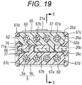
- Fig. 19 is a cross-sectional view taken along line D-D in Fig. 17 .
- the mounting of the cable holders 60 on the housing 20 and the terminal supports 70 is performed after the terminal supports 70 are mounted on the housing 20, in other words, is performed on the housing 20 in the state of Figs. 10 and 11 .
- the cable holders 60 are mounted in the abutment directions " ⁇ 1" and " ⁇ 2" on the top surfaces 77a of the terminal supports 70 mounted on the housing 20.
- the abutment directions of the paired terminal supports 70 are made the same as the mounting directions of the cable holders 60 on the terminal supports 70, which makes it suitable for mechanical production to enable a reduction in manufacturing cost.
- the cable holders 60 can be easily guide to the predetermined positions of the housing 20, using the arm portions 61. Furthermore, also if an undesirable force occurs on the cable holder 60 after the cable holder 60 is mounted on the housing 20, the arm portion 61 faces part of the housing 20 in the direction " ⁇ " along the lead-out direction of the cable 4; accordingly, the cable holder 60 can be maintained at the predetermined position of the housing 20.
- the cable holders 60 can be mounted together on, for example, the housing 20 by, for example, temporarily applying the force to simultaneously sandwich top surfaces 67a of the pair of opposing cable holders 60 with fingertips, a jig, or the like. It is preferable to provide a step portion 65 protruding upward on the top surface 67a of the cable holder 60 in such a manner as to more reliably allow a fingertip or the like to touch the top surface 67a of the cable holder 60.
- the electrical connector targeted in this case may have the top surface 67a with an area of, at most, approximately one square cm. In a case of such a small one, providing the step portion 65 is especially effective.
- twist pair cables 5 held by the cable holders 60 can be connected to the cable insulation-displacement portions 11b of the terminals 11, using the force that has been applied to mount the cable holders 60 on the housing 20.
Landscapes
- Coupling Device And Connection With Printed Circuit (AREA)
- Details Of Connecting Devices For Male And Female Coupling (AREA)
- Connections By Means Of Piercing Elements, Nuts, Or Screws (AREA)
- Connector Housings Or Holding Contact Members (AREA)
Abstract
Description
- The present invention relates to an electrical connector having terminal supports.
- A terminal support may be used as a separate body from a main body of a housing to hold a terminal of an electrical connector. For example,
Patent Document 1 illustrates an example of an electrical connector having a contact support block that can hold a plurality of terminals. It is configured in such a manner that the plurality of terminals is placed on both the upper and lower sides of the contact support block. The pluralities of terminals placed on the contact support block are placed in the connector in a state where a plate-shaped body is sandwiched in a gap formed between the terminals in the up-and-down direction. It is configured in such a manner that the contact with a counterpart connector is made on sides opposite to the gap sides between the terminals, in other words, on an upper exposed surface of the terminals placed on the upper side and on a lower exposed surface of the terminals placed on the lower side. - Patent Document 1: Japanese Patent No.
3362930 - It is necessary for a terminal support of the type disclosed in
Patent Document 1 to arrange a plurality of terminals on both upper and lower sides of the terminal support. As a result, it is necessary to arrange terminals on each side in a thickness direction of the terminal support without changing the orientation of the terminal support, or arrange terminals on one side in the thickness direction of the terminal support and then turn the terminal support, or a device for mounting terminals, upside down, and arrange terminals on the other side; therefore, the work is complicated. Moreover, in the terminal arrangement method disclosed inPatent Document 1, it is necessary for a connector of a type where the contact with a counterpart connector is made in a gap between contacts of terminals, unlike the connector of the type disclosed inPatent Document 1, to, for example, adjust the contact positions of the terminals, and there is a problem that increases in manufacturing time and manufacturing cost are incurred. - The invention of the present application has been made to solve such problems in the known technology, and especially an object thereof is to provide an electrical connector, in a type of connectors that comes into contact with a counterpart connector in a gap between contacts of terminals, in which the adjustment of contact positions of the terminals is easy and therefore the manufacture of the electrical connector is easy and the manufacturing cost is low.
- In order to solve the above problems, an electrical connector according to an aspect of the present invention includes: a housing; and paired terminal supports, each of the paired terminal supports is capable of supporting terminals in cantilever fashion, and upon being mounted on the housing in a state of abutting each other, the paired terminal supports are capable of forming a gap where a contacted object is inserted, between contacts of the terminals supported by the terminal supports in a direction along abutment directions of the paired terminal supports.
- According to the electrical connector of the aspect, an appropriate gap where a terminal contacted object is inserted can be formed between the contacts of the terminals by simply causing the paired terminal supports that support the terminals to abut in predetermined directions and mounting them on the housing as they are. Accordingly, the manufacture of the electrical connector is facilitated, and the manufacturing cost is also reduced.
- In the electrical connector of the aspect, it is preferable that in a state where substantially flat surfaces of the paired terminal supports abut each other, the terminal supports be mounted on the housing parallel to the substantially flat surfaces. According to the electrical connector of the aspect, it is configured in such a manner that the substantially flat surfaces abut each other and the mounting on the housing is performed parallel to the flat surfaces; accordingly, it is possible to make it suitable for mechanical production.
- In the electrical connector of the aspect, it is preferable that the terminal support be provided with a means for preventing displacement in a direction parallel to the substantially flat surfaces. According to the electrical connector of the aspect, the displacement prevention means is provided; accordingly, the terminal supports can be mounted on the housing in a more stable state.
- Moreover, in the electrical connector of the aspect, it is preferable that the electrical connector further include cable holders that are capable of mounting one end side of a cable thereon, and the cable holders be capable of being mounted on the terminal support along the abutment directions on sides of the paired terminal supports opposite to the abutment sides in the direction along the abutment directions.
- According to the electrical connector of the aspect, the abutment directions of the paired terminal supports are made the same as the mounting directions of the cable holders on these terminal supports; accordingly, the manufacturing cost can be reduced with a configuration more suitable for mechanical production.
- Furthermore, in the electrical connector of the aspect, it is preferable that the terminals include cable insulation-displacement portions vertically arranged in directions opposite to the abutment directions on the sides of the paired terminal supports opposite to the abutment sides in the direction along the abutment directions.
- According to the electrical connector of the aspect, the cable insulation-displacement portion is provided along the mounting direction of the cable holder; accordingly, the cable can be installed to the terminal, using a force at the time of mounting the cable holder.
- Moreover, in the electrical connector of the aspect, it is preferable that the terminal supports include fixing portions that fix at least part of the terminal on the sides of the paired terminal supports opposite to the abutment sides in the direction along the abutment directions, and at least other part of the terminal within a surface on the opposite side, the other part being located between the fixing portion and the cable insulation-displacement portion, be covered by an extending portion extending from the vertically arranged portion to the cable insulation-displacement portion side within the surface on the opposite side in a direction along a lead-out direction of the cable from the cable holder.
- According to the electrical connector of the aspect, the extending portion is provided; accordingly, it is possible to prevent a fault where, for example, a core in the cable exposed by the cable insulation-displacement portion is shortened to an adjacent terminal.
- Moreover, in the electrical connector of the aspect, it is preferable that the paired terminal supports have substantially the same size and shape.
- According to the electrical connector of the aspect, the terminal supports are made substantially the same size and shape; accordingly, the management of components is facilitated, and the manufacturing process is also simplified.
- An electrical connector in a type of connectors that comes into contact with a counterpart connector in a gap between contacts of terminals is provided in which the adjustment of contact positions of the terminals is easy and therefore the manufacture of the electrical connector is easy and the manufacturing cost is also low.
-
-
Fig. 1 is a perspective view of an electrical connector device using an electrical connector according to the present invention. -
Fig. 2 is a perspective view illustrating an internal structure of the electrical connector. -
Fig. 3 is an exploded perspective view of the internal structure ofFig. 2 . -
Fig. 4 is an exploded perspective view of, for example, a housing. -
Fig. 5 is a vertical cross-sectional view of, for example, the housing. -
Fig. 6 is a perspective view of terminal supports before abutment. -
Fig. 7 is a perspective view of the terminal supports after abutment. -
Fig. 8 is a plan view of the terminal support. -
Fig. 9 is a bottom view of the terminal support. -
Fig. 10 is a plan view illustrating a state where the terminal supports have been mounted on the housing. -
Fig. 11 is a perspective view illustrating the state where the terminal supports have been mounted on the housing. -
Fig. 12 is a perspective view of a cable holder when viewed from above. -
Fig. 13 is a perspective view of the cable holder when viewed from the bottom. -
Fig. 14 is a side view of the housing at temporary fixing positions. -
Fig. 15 is a cross-sectional view taken along line A-A inFig. 14 . -
Fig. 16 is a cross-sectional view taken along line B-B inFig. 14 . -
Fig. 17 is a side view of the housing at locking completion positions. -
Fig. 18 is a cross-sectional view taken along line C-C inFig. 17 . -
Fig. 19 is a cross-sectional view taken along line D-D inFig. 17 . - An electrical connector according to a preferred embodiment of the present invention is described hereinafter with reference to the accompanying drawings. Only the preferred embodiment of the present invention is illustrated here. However, naturally, this is not intended to limit the present invention.
-
Fig. 1 is a perspective view of anelectrical connector device 1 using anelectrical connector 10 according to the present invention. Theelectrical connector device 1 includes a pair of theelectrical connector 10 and acounterpart connector 90. Theelectrical connector 10 may be, for example, a connector of a cable type that is connected to anelectrical cable 4. Thecounterpart connector 90 may be, for example, a connector of a board type that is connected to aboard 3. Naturally, the connectors are not limited to them. As long as the present invention can be employed, for example, theelectrical connector 10 may be of the board type, and thecounterpart connector 90 may be of the cable type. Moreover, both of theconnector 10 and thecounterpart connector 90 may be of the board type, or both of them may be of the cable type. - The
electrical connector 10 can be mated with and removed from theboard connector 90 along an illustrated arrow "α" direction. In the description, for the sake of convenience, a description is given, letting a direction along the mating and removable directions of theelectrical connector 10 and theboard connector 90 be the "α" direction, letting a height direction with respect to theboard 3 of theboard connector 90 be a "β" direction, and letting a width direction of theboard connector 90 be "γ". - The mating of the
electrical connector 10 and theboard connector 90 can be locked using their shells. When theelectrical connector 10 and theboard connector 90 are mated, a tapered matedportion 50a provided on the shell of theelectrical connector 10 is inserted into a substantiallyrectangular mating hole 97 provided on a front surface of theboard connector 90, and lock portions protruding elastically from an upper side and a lower side of thedistal end portion 50a of theelectrical connector 10, for example, lock protrudingportions 35 protruding elastically fromholes 53 of the shell, are fitted into locked portions, for example, the through-holes 99, provided on a ceiling portion and a base plate portion of ashell 98 of theboard connector 90,. As a result, the mating of theelectrical connector 10 and theboard connector 90 is locked. In terms of the locking, thelock protruding portions 35 can be pulled out of the through-holes 99, by using, for example, abutton 13 provided on theelectrical connector 10, or more specifically, by pushing thebutton 13 exposed from ahood 12 into theelectrical connector 10 along the "β" direction. - The
board connector 90 mainly includes an insulatinghousing 92,terminals 96 that are held by the insulatinghousing 92 in a state of being partially exposed from the insulatinghousing 92, and theconductive shell 98 that covers an outer peripheral surface of the insulatinghousing 92. - The
mating hole 97 that allows a part of theconnector 10 to be mated is provided on a front surface of the insulatinghousing 92. Furthermore, a mating protrusion (not illustrated) that fits amating recess 28 formed in ahousing 20 of theconnector 10 is provided in themating hole 97. Theterminals 96 are arranged on the mating protrusion in a state of being exposed on one end side. On the other hand, theother end side 90a of theterminals 96 is soldered onto theboard 3. Apart 98a of theshell 98 is fixed at a predetermined position of theboard 3. Consequently, theshell 98 is connected to ground. -
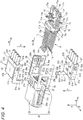
Fig. 2 is a perspective view illustrating an internal structure of theelectrical connector 10.Fig. 3 is an exploded perspective view of the internal structure ofFig. 2 . However,Fig. 2 is an illustration where thehood 12 and part of a sheath of theelectrical cable 4, which are illustrated inFig. 1 , have been removed.Fig. 3 is an illustration where the sheath of theelectrical cable 4 has been completely removed. Theelectrical cable 4 is assumed to include a plurality oftwist pair cables 5 as an example. However, naturally, the present application is not limited to thetwist pair cables 5. Theelectrical connector 10 mainly includes thehousing 20 formed of an insulating member such as resin, terminal supports 70 that supportterminals 11,cable holders 60 that hold thecables 5, aconductive shell 30 that covers an outer peripheral surface of, for example, thehousing 20, and the insulating hood 12 (refer toFig. 1 ) that covers an outer peripheral surface of theshell 30. - The
housing 20 includes ahousing body 29 that is formed in a substantially cuboid shape by being complemented by the terminal supports 70 and thecable holders 60, and an insertedportion 25 protruding from thehousing body 29 toward the mating side with the board connector 90 (refer toFig. 1 ). The insertedportion 25 is a portion that is inserted into the mating hole 97 (refer toFig. 1 ) of theboard connector 90. Themating recess 28 into which the mating protrusion (not illustrated) provided in themating hole 97 of theboard connector 90 is inserted is formed in the insertedportion 25. - The
shell 30 includes amain body shell 31, a plate-shapedshell 40, and atubular shell 50. The plate-shapedshell 40 and themain body shell 31 mainly cover outer peripheral surfaces of side portions of, for example, thehousing body 29. The plate-shapedshell 40 mainly covers outer peripheral surfaces of side portions of, for example, thehousing body 29 that is not covered by themain body shell 31. Thetubular shell 50 mainly covers outer peripheral surfaces of side portions of the insertedportion 25 with a slightly small diameter protruding from thehousing body 29. - The
main body shell 31 is formed by blanking one metal sheet and bending the blank, and has a substantially angular U-shape in cross section as a whole, and mainly includes abase 36, anelastic piece 33 extending frontward of thebase 36, and aswaging portion 36a of theelectrical cable 4 extending rearward of thebase 36. A mountingpiece 36c used to fix thecable 4 is provided in a rear part of thebase 36. Thebase 36 and theelastic piece 33 are elastically connected at a rear end portion of thebase 36 via asupport portion 32 formed as a folded-over portion of a substantially U-shape in cross section. Theelastic piece 33 has a free end on the mating side with theboard connector 90. Furthermore, thelock protruding portion 35 used to lock to theboard connector 90 is provided at the free end. - The plate-shaped
shell 40 is formed by blanking one metal sheet and bending the blank as in themain body shell 31, and has a substantially angular U-shape in cross section as a whole, and includes abase 42 and two opposingplate portions 46. The plate-shapedshell 40 is mounted in such a manner as to sandwich themain body shell 31 between the two opposingplate portions 46. When themain body shell 31 is mounted, a tongue-shapedmounting piece 47 provided to theplate portion 46 is locked to anedge 36b of a mounting hole provided in themain body shell 31 and fixed to theedge 36b. - The
tubular shell 50 is also formed by blanking one metal sheet and bending the blank as in themain body shell 31 and the plate-shapedshell 40, and has a substantially rectangular tubular shape as a whole, and includes atubular base 55, mountingpieces base 55, and a pair of standingpieces 54 provided vertically outward on an edge of thebase 55. Thetubular shell 50 is mounted in such a manner as to insert the insertedportion 25 of thehousing 20 into the tube of thebase 55. At this point in time, the pair of standingpieces 54 is positioned with respect to thehousing 20 by, for example, abutting a ring-shapedstep surface 21c formed using a difference in diameter between the insertedportion 25 and the housingmain body 29 of thehousing 20. Ahole 51a is provided on the mountingpiece 51. When thetubular shell 50 is mounted, alocking protruding portion 21a provided to abase 21 of thehousing 20 is fitted in thehole 51a. Moreover, lockingportions 52a are provided to the mountingpiece 52. The lockingpieces 52a are locked at predetermined portions of themain body shell 31. - When the
tubular shell 50 is mounted on the insertedportion 25, thelock protruding portion 35 provided at the free end of theelastic piece 33 of themain body shell 31 is brought into a state of elastically protruding from thehole 53 provided on thebase 55 of thetubular shell 50. Moreover, at this point in time, a portion 33' on the free end side of theelastic piece 33 is placed in a gap formed between thetubular shell 50 and the insertedportion 25, and is protected by thetubular shell 50. It is preferable to provide anindentation 25a that releases theelastic piece 33 on a side surface of the insertedportion 25. Consequently, a portion where the portion 33' on the free end side of theelastic piece 33 is placed can be provided without increasing the size of the device. -
Fig. 4 illustrates a perspective view of thehousing 20 together with the terminal supports 70 and thecable holders 60, which have been removed from thehousing 20. Furthermore,Fig. 5 illustrates a vertical cross-sectional view of thehousing 20, and the terminal supports 70 and thecable holders 60, which have been mounted on thehousing 20.Fig. 5 corresponds to a cross-sectional view taken along line E-E inFig. 19 described below and, for the sake of convenience, is assumed to illustrate a state where thetwist pair cables 5 have been connected. Thehousing body 29 includes thethick base 21, and two opposing plate-shapedside walls 26 extending rearward of thebase 21, that is, opposite the insertedportion 25. The paired terminal supports 70 and thecable holders 60 paired likewise are placed in aspace 26f formed between these plate-shapedside walls 26. - It is preferable that both of the paired terminal supports 70 have the same size and shape. Similarly, it is preferable that both of the paired
cable holders 60 have the same size and shape. Having the same size and shape makes the management of components easy and also makes the manufacturing process simple. However, it is not necessarily required to have the same size and shape, and different sizes and shapes are also acceptable. Moreover, as long as the above effects can be obtained, having completely the same size and shape is not necessarily required, and having substantially the same size and shape is sufficient. - The
terminal support 70 can support a plurality of theterminals 11 in cantilever fashion. Theterminals 11 may be integrated by integral molding at the time of manufacture, or may be integrated with theterminal support 70 from the rear or above, using press-fitting or the like. In this example, a description is given assuming integral molding. Part of the terminal 11 is still exposed to the outside after being integrated. For example, a front part of the terminal 11, in other words, the vicinity of adistal end 11f of the terminal 11 extending to the base 21 side of thehousing 20, and a rear part of the terminal 11, in other words, a cable insulation-displacement portion 11b to which thetwist pair cable 5 is forced to be connected and awiring portion 11e near the cable insulation-displacement portion 11b, are exposed. Thedistal end 11f side of the terminal 11 can be elastically displaced along the direction γ. - The
terminal support 70 includes a plate-shapedmain body 77. A vertically arrangedportion 75 is provided on atop surface 77a of themain body 77, alock projection 71a protruding outward is provided on each of the left and right side surfaces of themain body 77, and anotch 76 of a U-shape in plan view cut out inward is provided at a rear edge of themain body 77. - At the time of assembly, firstly, the paired terminal supports 70 are abutted against each other in predetermined directions.
Figs. 6 and7 illustrate a perspective view of the terminal supports 70 before the abutment and a perspective view of the terminal supports 70 after the abutment, respectively. Furthermore,Figs. 8 and9 illustrate a plan view of eachterminal support 70 and a bottom view thereof, respectively. - As in this example, it is preferable that the paired terminal supports 70 be abutted on
flat undersurfaces 77b thereof. The surfaces are made flat to enable abutment in a more stable state. However, if stable abutment can be performed, the surfaces are not necessarily made flat. Moreover, even if the surfaces are made flat, the surfaces are simply required to be substantially flat to a degree that allows stable abutment. The abutment is preferably performed in such a manner as to bring both of them into direct contact with each other as in this example. The direct contact allows the facilitation of the manufacture of the electrical connector. However, direct contact is not necessarily required. A member may be sandwiched between them. - When the pair of terminal supports 70 is abutted against each other, the
terminals 11 supported by the terminal supports 70 can form a gap "G" (refer toFigs. 5 and7 ) into which a contacted object, for example, the mating protrusion provided in themating hole 97 of the board connector 90 (refer toFig. 1 ), is inserted, betweencontacts 11d of theterminals 11. The gap "G" is formed in the direction "γ" along abutment directions "γ1" and "γ2" of the paired terminal supports 70. - A displacement prevention means may be provided to prevent the terminal supports 70 from being displaced after the abutment. For example, a through-
hole 73a and a protrudingportion 73b may be provided to eachterminal support 70, and the pair of terminal supports 70 may be fitted at two points to each other in such a manner as to fit the protrudingportion 73b of one terminal support into the through-hole 73a of the other terminal support. Naturally, displacement may be prevented not limited to by the through-hole 73a and the protrudingportion 73b but in other methods. - The vertically arranged
portions 75 are vertically arranged on the top surfaces "77a" being surfaces on sides opposite to abutment-side surfaces of the paired terminal supports 70, in other words, theundersurfaces 77b in the direction "γ" along the abutment directions "γ1" and "γ2", in the directions "γ2" and "γ1" opposite to the abutment directions "γ1" and "γ2". The terminal 11 is fixed by the vertically arrangedportion 75 to theterminal support 70 near abase 11c formed in a substantially "S" shape. Alocking protruding portion 75a that is locked to a corresponding locking portion (61a) provided to thecable holder 60 is provided on one of the left and right side surfaces of the vertically arrangedportion 75. - The cable insulation-
displacement portion 11b extends in the same direction as the vertically arrangedportion 75, on thetop surface 77a of themain body 77 of theterminal support 70. The cable insulation-displacement portions 11b of the plurality ofterminals 11 are alternately placed along the direction α. Adistal end portion 14 of the cable insulation-displacement portion 11b is bifurcated to form a groove. It is configured in such a manner that thetwist pair cable 5 held by thecable holder 60 is pressed-fitted in the groove. Anouter sheath 5b of thetwist pair cable 5 press-fitted in the groove (refer toFig. 5 ) is cut here. As a result, aninternal core 5a (refer toFig. 5 ) is caught in the groove to bring thecable 5 and the terminal 11 into conduction. - Each of the cable insulation-
displacement portions 11b is coupled to theplacement portion 11e.Pitch changing portions 15 may be provided to part or all of a plurality of theplacement portions 11e (in this example, three of four terminals) to change the interval between thewiring portions 11e in a pitch direction "β" being an arrangement direction of the terminals 11 (refer toFig. 8 ). Thesepitch changing portions 15 are provided; accordingly, the distance between the cable insulation-displacement portions 11b in the pitch direction "β" can be increased as compared to the distance between thedistal ends 11f, and the pressure connection work can be facilitated. - It is preferable to provide an extending
portion 74 extending from the vertically arrangedportion 75, on theterminal support 70, to prevent, for example, a part of thecore 5a exposed from the distal end (terminal) of thecable 5 held by thecable holder 60 from being shortened to an adjacent terminal. The extendingportion 74 extends from the vertically arrangedportion 75 toward the cable insulation-displacement portion 11b side within thetop surface 77a of theterminal support 70, and covers at least part of thewiring portion 11e of the terminal 11 between the vertically arrangedportion 75 and the cable insulation-displacement portion 11b in the direction "α" along a lead-out direction "α2" of the cable 45 from thecable holder 60. As well illustrated inFig. 5 , the extendingportion 74 is preferable to extend to the cable insulation-displacement portion 11b side with respect to afront surface 67e of thecable holder 60. Ataper 74a for preventing a collision with thecable holder 60 is formed at a distal end of the extendingportion 74. - A method for mounting the terminal supports 70 on the
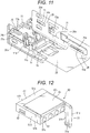
housing 20 is described with reference also toFigs. 10 and11 .Fig. 10 is a plan view illustrating a state where the terminal supports 70 have been mounted on thehousing 20.Fig. 11 is a perspective view of them when viewed from the bottom. - The pair of terminal supports 70 abutting each other are mounted on the
housing 20 as they are, for example, parallel to the flat abutting surfaces that abut each other. The terminal supports 70 are guided into thehousing 20 in a stable state by sliding left and right side surfaces 71 of the terminal supports 70 alongguide grooves 26c provided on inner walls of the plate-shapedside walls 26. At this point in time, the pluralities of theterminals 11 supported by the terminal supports 70 are inserted into the insertedportion 25 throughterminal insertion holes 21b (refer toFig. 4 ) provided on aninner wall 21e of thebase 21. At the time of completing the mounting, a press-fittedportion 11a of the terminal 11 is press-fitted in the vicinity of an entrance of theterminal insertion hole 21b. Moreover, a fontouter wall 75b of the vertically arrangedportion 70 of theterminal support 70 comes face to face with theinner wall 21e of thebase 21. Apositioning projection 72 provided to theterminal support 70 is fitted into apositioning hole 27 of the base 22. Furthermore, thelock protruding portions 71a provided on the side surfaces 71 of theterminal support 70 are fitted intolock holes 26b provided on the plate-shapedside walls 26 of thehousing 20 to lock theterminal support 70 to thehousing 20. The mounted state of the terminal supports 70 can also be checked throughwindows 26e provided on the plate-shapedside walls 26. In this manner, the flat surfaces are abutted against each other to perform mounting on the housing parallel to the flat surfaces; accordingly, the assembly can be made more suitable for mechanical production. - According to this configuration, in this manner, the paired terminal supports 70 that support the
terminals 11 are simply abutted against each other, and mounted on thehousing 20 as they are. Accordingly, the appropriate gap "G" can be formed between the contacts of theterminals 11. Therefore, it is possible to facilitate the manufacture of theelectrical connector 10 and reduce the manufacturing cost. Especially when the abutting surfaces are made flat and the mounting is performed on thehousing 20 parallel to the flat surfaces, the assembly can be made more suitable for mechanical production. - The configuration of the
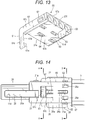
cable holder 60 is described with reference also toFigs. 12 and13 .Fig. 12 is a perspective view of thecable holder 60 when viewed from above.Fig. 13 is a perspective view when viewed from the bottom. However, inFigs. 12 and13 , thetwist pair cables 5 illustrated in, for example,Fig. 4 are omitted. - The
cable holder 60 mainly includes a substantially cuboidmain body 67, and acantilevered arm portion 61 extending from themain body 67 in the mounting directions "γ1" and "γ2" of thecable holders 60 on thehousing 20. Thearm portion 61 is coupled to thefront surface 67e and oneside surface 67c of themain body 67 on one end side opposite to the free end, and is provided in a state of being flush with the oneside surface 67c of themain body 67 and in a state of protruding frontward of thefront surface 67e of themain body 67. Thearm portion 61 is preferable to be provided in such a manner as to be elastically displaced in a thickness direction. A plurality of through-holes 63 through which the terminal 11 is inserted is provided in the front-and-rear direction (the direction "α") in themain body 67. These through-holes 63 are used to mount one end side of thetwist pair cables 5 on thecable holder 60. The mounted one end side of the twist pair cable goes from arear surface 67f to the vicinity of thefront side 67 side e of the main body 67 (refer to, for example,Fig. 5 ). The inner diameter of the through-hole 63 can be set to be substantially the same as or slightly smaller than the outer diameter of thecable 5. Consequently, an outer peripheral surface of thecable 5 is caught on an inner peripheral surface of the through-hole 63, which can prevent thecable 5 from accidentally coming out of the through-hole 63. - A
locking protruding portion 62 that is locked in alocking hole 26a (refer to, for example,Fig. 11 ) provided on the plate-shapedside wall 26 of thehousing 20 is provided on each of left and right side surfaces 67c and 67d of themain body 67. Moreover, thelocking protruding portion 61a that is locked to thelocking protruding portion 75a (refer to, for example,Fig. 11 ) provided on the vertically arrangedportion 75 of theterminal support 70 is provided near the free end of thearm portion 61. Thelocking protruding portions 62 of thecable holder 60 and the lockingholes 26a on thehousing 20 side, and thelocking protruding portion 61a of thecable holder 60 and thelocking protruding portion 75a of theterminal support 70 are provided along the mounting directions "γ1" and "γ2" of thecable holders 60 on thehousing 20. Thecable holder 60 can be locked to thehousing 20, using these locking means. In this manner, in the embodiment, the locking of thelocking protruding portion 62 of thecable holder 60 and thelocking hole 26a on thehousing 20 side, and the locking of thelocking protruding portion 61a of thecable holder 60 and thelocking protruding portion 75a of theterminal support 70 allow thecable holder 60 to be locked at different points respectively to thehousing 20 and theterminal support 70. The fixing of these three members (thehousing 20, theterminal support 70, and the cable holder 60) can be strengthened. A plurality of locking means is not necessarily provided (in the embodiment, at two points). However, a plurality of them is provided to more reliably fix thecable holders 60 and thehousing 20. Moreover, if a plurality of them is provided, thelocking protruding portion 62 and thelocking protruding portion 61a, and theircorresponding locking hole 26a and lockingprotruding portion 75a are preferably spaced apart from each other in the direction "α" along the lead-out direction "α2" of thetwist pair cable 5. They are spaced apart, and are locked at different positions in the lead-out direction of the cable; accordingly, thecable holder 60 can be fixed to thehousing 20 in a more stable state. - An
insertion hole 64 into which the cable insulation-displacement portion 11b of theterminal support 70 is inserted is provided on anundersurface 67b of themain body 67. Theinsertion hole 64 communicates with the through-hole 63 through which thetwist pair cable 5 is inserted, and is configured in such a manner as to be capable of cutting thesheath 5b (refer toFig. 5 ) of thetwist pair cable 5 inserted through the through-hole 63, with the cable insulation-displacement portion 11b inserted through the through-hole 64, when thecable holder 60 is mounted on thehousing 20. - Moreover, a protruding
portion 66 that is fitted in thenotch 76 provided on theterminal support 70 is provided on theundersurface 67b of themain body 67. The protrudingportion 66 is vertically arranged on a surface on the mounting side of thecable holder 60 on thehousing 20, that is, theundersurface 67b, in the mounting directions "γ1" and "γ2" of thecable holders 60 on thehousing 20, that is, in the same direction as thearm portion 61. - A method for mounting the
cable holders 60 on thehousing 20 is described with reference also toFigs. 14 to 19 . -
Figs. 14 to 16 illustrate temporary fixing positions, in other words, a state where thelocking protruding portions cable holder 60 and thecorresponding locking portions housing 20 side are not yet locked.Fig. 14 is a side view of thehousing 20 at the temporary fixing positions.Fig. 15 is a cross-sectional view taken along line A-A inFig. 14 .Fig. 16 is a cross-sectional view taken along line B-B inFig. 14 . - On the other hand,
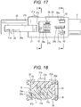
Figs. 17 to 19 illustrate locking completion positions, in other words, a state where thelocking protruding portions cable holder 60 and thecorresponding locking portions housing 20 side have already been locked.Fig. 17 is a side view of thehousing 20 at the locking completion positions.Fig. 18 is a cross-sectional view taken along line C-C inFig. 17 .Fig. 19 is a cross-sectional view taken along line D-D inFig. 17 . - The mounting of the
cable holders 60 on thehousing 20 and the terminal supports 70 is performed after the terminal supports 70 are mounted on thehousing 20, in other words, is performed on thehousing 20 in the state ofFigs. 10 and11 . Thecable holders 60 are mounted in the abutment directions "γ1" and "γ2" on thetop surfaces 77a of the terminal supports 70 mounted on thehousing 20. In this manner, the abutment directions of the paired terminal supports 70 are made the same as the mounting directions of thecable holders 60 on the terminal supports 70, which makes it suitable for mechanical production to enable a reduction in manufacturing cost. - When the
cable holders 60 are mounted on the terminal supports 70 and thehousing 20, thecable holders 60 are positioned at the temporary fixing positions illustrated inFigs. 14 to 16 before being actually locked and fixed. Thelocking protruding portion 61a and thetaper 62a of thelocking protruding portion 62, which are provided to thecable holder 60, collide respectively with thelocking protruding portion 75a provided on the vertically arrangedportion 75 of theterminal support 70 and anupper edge 26d of the plate-shapedside wall 26, which are part of thehousing 20 side. As a result, thecable holders 60 are positioned in the mounting directions "γ1" and "γ2" in a state of being more apart from thehousing 20 than at the locking completion positions. In this manner, the positions are determined to be the temporary fixing positions before locking is actually performed; accordingly, thecable holders 60 can be reliably mounted at predetermined positions of thehousing 20 in a more stable state. - In addition, when the
cable holders 60 are mounted on the terminal supports 70 and thehousing 20, thearm portions 61 of thecable holders 60 are inserted into holes 78 (refer toFig. 10 ) formed on thehousing 20 side. Thehole 78 is formed by thebase 21, the plate-shapedside wall 26, and theterminal support 70, which configure thehousing 20. When thearm portion 61 is inserted into thehole 78, at least part of thearm portion 61, for example, side surfaces 61b and 61c in the front-and-rear direction can come face to face with ataper 77c formed on theside surface 71 of theterminal support 70, and theinner wall 21e of thebase 21, which are part of thehousing 20, in the direction "α" along the lead-out direction "α2" of thecable 4 from thecable holder 60. As a result, when thecable holders 60 are mounted on thehousing 20, it is possible to regulate the movement of thecable holders 60 with respect to thehousing 20 in the "α" direction and easily position thecable holders 60 at the predetermined positions of thehousing 20. Moreover, it is also possible to easily guide thecable holders 60 to the predetermined positions of thehousing 20, using thearm portions 61. Furthermore, also if an undesirable force occurs on thecable holder 60 after thecable holder 60 is mounted on thehousing 20, thearm portion 61 faces part of thehousing 20 in the direction "α" along the lead-out direction of thecable 4; accordingly, thecable holder 60 can be maintained at the predetermined position of thehousing 20. - After being positioned at the temporary fixing positions illustrated in
Figs. 14 to 16 , thecable holders 60 can be mounted together on, for example, thehousing 20 by, for example, temporarily applying the force to simultaneouslysandwich top surfaces 67a of the pair of opposingcable holders 60 with fingertips, a jig, or the like. It is preferable to provide astep portion 65 protruding upward on thetop surface 67a of thecable holder 60 in such a manner as to more reliably allow a fingertip or the like to touch thetop surface 67a of thecable holder 60. The electrical connector targeted in this case may have thetop surface 67a with an area of, at most, approximately one square cm. In a case of such a small one, providing thestep portion 65 is especially effective. - As illustrated in
Figs. 17 to 19 , at the locking completion position, thelocking protruding portion 61a provided to thearm portion 61 of thecable holder 60 moves over and is locked to thelocking protruding portion 75a provided to the vertically arrangedportion 75 of theterminal support 70. Moreover, thelocking protruding portions 62 provided on the side surfaces 67c and 67d of themain body 67 of thecable holder 60 move over theupper edges 26d of the plate-shapedside walls 26 of thehousing 20, and are fitted in the lockingholes 26a. Moreover, at this point in time, the protrudingportion 66 provided on thecable holder 60 is placed through thenotch 76 provided to theterminal support 70 in a state of being in close proximity to the counterpart cable holder. - When the
cable holders 60 shift from the temporary fixing positions illustrated inFigs. 14 to 16 to the locking completions position illustrated inFigs. 17 and19 , thetwist pair cables 5 held by thecable holders 60 can be connected to the cable insulation-displacement portions 11b of theterminals 11, using the force that has been applied to mount thecable holders 60 on thehousing 20. - When an excessive force is applied to the
cable holders 60 at the time of the shift, thecable holders 60 may be brought close to each other more than necessary and theconnector 10 may be broken. However, if such a force is applied, the protrudingportion 66 provided on thecable holder 60 collides first with thecounterpart cable holder 60 before thecable holder 60 is pressed against theterminal holder 70. Accordingly, damage to thecable holder 60 can be reduced. Especially the protrudingportion 66 is located on the lead-out (the arrow "α2") side of thecable 5 to which an excessive force tends to be applied, and further is located at two points in the arrangement direction (the arrow "β") of thecable 5; therefore, it is highly effective. - The present invention is not limited to the above-mentioned embodiment, and other various modifications can be made thereto. The drawings and description of the present application are mere exemplifications, and are not limited to them.
-
- 1
- Electrical connector device
- 4
- Electrical cable
- 5
- Twist pair cable
- 10
- Cable connector
- 11
- Terminal
- 20
- Insulating housing
- 21
- Base
- 28
- Mating recess
- 30
- Conductive shell
- 31
- Main body shell
- 40
- Plate-shaped shell
- 50
- Tubular shell
- 60
- Cable holder
- 61
- Arm
- 61a
- Locking protruding portion
- 61b
- Rear surface
- 61c
- Front surface
- 62
- Locking protruding portion
- 70
- Terminal support
- 74
- Extending portion
- 75
- Vertically arranged portion (fixing portion)
- 78
- Hole
- 90
- Board connector
Claims (7)
- An electrical connector comprising:a housing; andpaired terminal supports, whereineach of the paired terminal supports is capable of supporting terminals in cantilever fashion, andupon being mounted on the housing in a state of abutting each other, the paired terminal supports are capable of forming a gap where a contacted object is inserted, between contacts of the terminals supported by the terminal supports in a direction along abutment directions of the paired terminal supports.
- The electrical connector according to claim 1, wherein in a state where substantially flat surfaces of the paired terminal supports abut each other, the terminal supports are mounted on the housing parallel to the substantially flat surfaces.
- The electrical connector according to claim 2, wherein the terminal support is provided with a means for preventing displacement in a direction parallel to the substantially flat surfaces.
- The electrical connector according to any of claims 1 to 3, further comprising cable holders that are capable of mounting one end side of a cable thereon, wherein the cable holders are capable of being mounted on the terminal support along the abutment directions on sides of the paired terminal supports opposite to the abutment sides in the direction along the abutment directions.
- The electrical connector according to claim 4, wherein the terminals include cable insulation-displacement portions vertically arranged in directions opposite to the abutment directions on the sides of the paired terminal supports opposite to the abutment sides in the direction along the abutment directions.
- The electrical connector according to claim 5, wherein
the terminal supports include fixing portions that fix at least part of the terminal on the sides of the paired terminal supports opposite to the abutment sides in the direction along the abutment directions, and
at least other part of the terminal within a surface on the opposite side, the other part being located between the fixing portion and the cable insulation-displacement portion, is covered by an extending portion extending from the vertically arranged portion to the cable insulation-displacement portion side within the surface on the opposite side in a direction along a lead-out direction of the cable from the cable holder. - The electrical connector according to any of claims 1 to 6, wherein the paired terminal supports have substantially the same size and shape.
Applications Claiming Priority (2)
| Application Number | Priority Date | Filing Date | Title |
|---|---|---|---|
| JP2016142463A JP6757611B2 (en) | 2016-07-20 | 2016-07-20 | Electrical connector with terminal support |
| PCT/JP2017/025284 WO2018016388A1 (en) | 2016-07-20 | 2017-07-11 | Electrical connector having terminal support |
Publications (3)
| Publication Number | Publication Date |
|---|---|
| EP3490081A1 true EP3490081A1 (en) | 2019-05-29 |
| EP3490081A4 EP3490081A4 (en) | 2020-03-04 |
| EP3490081B1 EP3490081B1 (en) | 2021-10-06 |
Family
ID=60992951
Family Applications (1)
| Application Number | Title | Priority Date | Filing Date |
|---|---|---|---|
| EP17830907.6A Active EP3490081B1 (en) | 2016-07-20 | 2017-07-11 | Electrical connector having terminal supports |
Country Status (5)
| Country | Link |
|---|---|
| US (1) | US10505288B2 (en) |
| EP (1) | EP3490081B1 (en) |
| JP (1) | JP6757611B2 (en) |
| CN (1) | CN109478750B (en) |
| WO (1) | WO2018016388A1 (en) |
Families Citing this family (18)
| Publication number | Priority date | Publication date | Assignee | Title |
|---|---|---|---|---|
| EP3490078A4 (en) * | 2016-07-20 | 2020-03-04 | Hirose Electric Co., Ltd. | CABLE CONNECTOR HAVING CABLE HOLDING BODIES |
| JP6757497B2 (en) * | 2017-02-03 | 2020-09-23 | 株式会社オートネットワーク技術研究所 | Shield terminal |
| JP7282528B2 (en) * | 2019-01-21 | 2023-05-29 | モレックス エルエルシー | Cable connector and cable connector assembly method |
| JP7201483B2 (en) * | 2019-03-06 | 2023-01-10 | 矢崎総業株式会社 | IDC connector |
| EP3758163A1 (en) * | 2019-06-24 | 2020-12-30 | TE Connectivity Nederland B.V. | Plug insert for a connector assembly and connector assembly |
| JP7249226B2 (en) * | 2019-07-18 | 2023-03-30 | 日本航空電子工業株式会社 | Connectors and cable harnesses |
| CN110649413A (en) * | 2019-09-10 | 2020-01-03 | 安徽三竹智能科技股份有限公司 | Crimp Type Signal Connector Structure |
| US12322914B2 (en) | 2019-11-19 | 2025-06-03 | Panduit Corp. | Field terminable single pair ethernet connector with angled contacts |
| US11811181B2 (en) * | 2019-11-19 | 2023-11-07 | Panduit Corp. | Field terminable single pair ethernet connector with angled contacts |
| CN211829308U (en) * | 2020-01-22 | 2020-10-30 | 泰科电子(上海)有限公司 | Connector with a locking member |
| JP7390228B2 (en) * | 2020-03-24 | 2023-12-01 | ヒロセ電機株式会社 | Cable connector with cable holder and method for manufacturing this cable connector |
| USD999171S1 (en) * | 2021-01-20 | 2023-09-19 | Hirose Electric Co., Ltd. | Electrical connector |
| JP7507111B2 (en) * | 2021-03-03 | 2024-06-27 | ヒロセ電機株式会社 | Electrical Connectors |
| JP7534717B2 (en) * | 2021-03-17 | 2024-08-15 | Smk株式会社 | Cable connector and assembly method thereof |
| JP7575993B2 (en) * | 2021-04-23 | 2024-10-30 | 矢崎総業株式会社 | Connectors and wires with connectors |
| JP2023026809A (en) * | 2021-08-16 | 2023-03-01 | 日本航空電子工業株式会社 | connector |
| US11677186B2 (en) * | 2021-08-17 | 2023-06-13 | Littelfuse, Inc. | Quick assembly plug connector |
| JP1710982S (en) * | 2021-10-22 | 2022-03-28 | Electrical connector |
Family Cites Families (21)
| Publication number | Priority date | Publication date | Assignee | Title |
|---|---|---|---|---|
| JP3078616B2 (en) * | 1991-08-30 | 2000-08-21 | ケル株式会社 | Plug connector and manufacturing method thereof |
| US5273459A (en) | 1992-10-01 | 1993-12-28 | The Whitaker Corporation | Connector feature for improved contact wiping |
| US5376108A (en) | 1993-05-20 | 1994-12-27 | Telectronics Pacing Systems, Inc. | Electrode lead anchoring apparatus and method employing dual suture collars |
| EP0850499B1 (en) | 1995-09-15 | 1999-03-10 | The Whitaker Corporation | Shielded electrical connector |
| JP3651251B2 (en) | 1998-04-08 | 2005-05-25 | 住友電装株式会社 | IDC connector |
| JP2000100539A (en) * | 1998-09-28 | 2000-04-07 | Sumitomo Wiring Syst Ltd | Connector and its manufacture |
| US6454605B1 (en) * | 1999-07-16 | 2002-09-24 | Molex Incorporated | Impedance-tuned termination assembly and connectors incorporating same |
| JP2005149935A (en) * | 2003-11-17 | 2005-06-09 | Fujikura Ltd | IDC joint connector |
| TWM260022U (en) * | 2004-05-11 | 2005-03-21 | Su-Lan Yanglee | Terminal bus connector with the terminal port plastic core |
| CN200959372Y (en) * | 2006-08-11 | 2007-10-10 | 金胜国际股份有限公司 | electrical connector |
| CN201204261Y (en) * | 2008-04-01 | 2009-03-04 | 王风良 | Thorn-holding type electronic connector |
| CN201185236Y (en) * | 2008-04-07 | 2009-01-21 | 东莞长安乌沙联基电业制品厂 | High Definition Multimedia Digital Connector |
| CN101465508B (en) * | 2009-01-14 | 2011-09-14 | 永泰电子(东莞)有限公司 | Piercing type terminal, electric connector and production process thereof |
| JP3160343U (en) * | 2010-02-12 | 2010-06-24 | 正▲うえ▼精密工業股▲ふん▼有限公司 | High resolution multimedia interface connector |
| TWM395282U (en) * | 2010-07-28 | 2010-12-21 | Concraft Holding Co Ltd | Having wire puncturing and clamping structure of electrical |
| US9450326B2 (en) * | 2010-12-17 | 2016-09-20 | Leoni Kabel Holding Gmbh | Data cable connector module for assembly to cable with a fixation element for positioning and fixing of cable conductors of a multi core cable |
| EP2466697B1 (en) * | 2010-12-17 | 2020-01-22 | LEONI Kabel GmbH | Data cable connection module and method for producing same on a cable |
| CN103579798B (en) * | 2012-08-07 | 2016-08-03 | 泰科电子(上海)有限公司 | Electric connector and conducting terminal assembly thereof |
| US9419391B2 (en) * | 2013-08-20 | 2016-08-16 | Panduit Corp. | Communication connector |
| CN203747107U (en) * | 2014-03-17 | 2014-07-30 | 万安协讯电子有限公司 | Multi-row serial port high frequency data transmission connecting device |
| CN105633732A (en) * | 2016-02-29 | 2016-06-01 | 孙开宝 | A Type-C anti-EMI plug connector |
-
2016
- 2016-07-20 JP JP2016142463A patent/JP6757611B2/en active Active
-
2017
- 2017-07-11 US US16/317,442 patent/US10505288B2/en active Active
- 2017-07-11 CN CN201780044698.9A patent/CN109478750B/en active Active
- 2017-07-11 WO PCT/JP2017/025284 patent/WO2018016388A1/en not_active Ceased
- 2017-07-11 EP EP17830907.6A patent/EP3490081B1/en active Active
Also Published As
| Publication number | Publication date |
|---|---|
| JP2018014212A (en) | 2018-01-25 |
| EP3490081B1 (en) | 2021-10-06 |
| CN109478750A (en) | 2019-03-15 |
| JP6757611B2 (en) | 2020-09-23 |
| US10505288B2 (en) | 2019-12-10 |
| WO2018016388A1 (en) | 2018-01-25 |
| CN109478750B (en) | 2020-08-28 |
| EP3490081A4 (en) | 2020-03-04 |
| US20190229438A1 (en) | 2019-07-25 |
Similar Documents
| Publication | Publication Date | Title |
|---|---|---|
| US10505288B2 (en) | Electrical connector having terminal supports | |
| US10965054B2 (en) | Cable connector having cable holders | |
| CN109962356B (en) | L-shaped electrical connector for circuit board and method for producing the same | |
| EP2922150B1 (en) | Connector | |
| EP3422488B1 (en) | Connector comprising shell having locking mechanism, and connector device | |
| US9325093B2 (en) | Connector terminal and connector including the same | |
| CN104347991A (en) | Connector | |
| KR20190124659A (en) | Electric connector for circuit substrate | |
| TWI729127B (en) | Coaxial connector and coaxial connector device using the coaxial connector | |
| US9246260B2 (en) | Electrical connector | |
| US10056714B2 (en) | Connector device including coming-off preventing structure | |
| JP2017079214A (en) | connector | |
| KR102030023B1 (en) | Plug connector | |
| EP3190667A1 (en) | Connector and connector assembly | |
| JP2019117693A (en) | Electric connector for circuit board | |
| JP2022186850A (en) | movable connector | |
| KR101725380B1 (en) | Connector terminal and connector including the same | |
| JP2016076318A (en) | Flat electrical connector with conductor | |
| US20180366859A1 (en) | Electrical connector | |
| JP7811361B2 (en) | connector | |
| JP6396545B1 (en) | Board to board connector | |
| JP7274007B2 (en) | CABLE RETAINING MEMBER AND CABLE CONNECTOR DEVICE HAVING CABLE RETAINING MEMBER | |
| JP2007149383A (en) | Fastening terminal |
Legal Events
| Date | Code | Title | Description |
|---|---|---|---|
| STAA | Information on the status of an ep patent application or granted ep patent |
Free format text: STATUS: THE INTERNATIONAL PUBLICATION HAS BEEN MADE |
|
| PUAI | Public reference made under article 153(3) epc to a published international application that has entered the european phase |
Free format text: ORIGINAL CODE: 0009012 |
|
| STAA | Information on the status of an ep patent application or granted ep patent |
Free format text: STATUS: REQUEST FOR EXAMINATION WAS MADE |
|
| 17P | Request for examination filed |
Effective date: 20190213 |
|
| AK | Designated contracting states |
Kind code of ref document: A1 Designated state(s): AL AT BE BG CH CY CZ DE DK EE ES FI FR GB GR HR HU IE IS IT LI LT LU LV MC MK MT NL NO PL PT RO RS SE SI SK SM TR |
|
| AX | Request for extension of the european patent |
Extension state: BA ME |
|
| DAV | Request for validation of the european patent (deleted) | ||
| DAX | Request for extension of the european patent (deleted) | ||
| A4 | Supplementary search report drawn up and despatched |
Effective date: 20200203 |
|
| RIC1 | Information provided on ipc code assigned before grant |
Ipc: H01R 13/41 20060101ALN20200128BHEP Ipc: H01R 13/405 20060101ALN20200128BHEP Ipc: H01R 13/514 20060101ALI20200128BHEP Ipc: H01R 13/506 20060101ALI20200128BHEP Ipc: H01R 24/60 20110101AFI20200128BHEP Ipc: H01R 9/03 20060101ALI20200128BHEP Ipc: H01R 11/05 20060101ALN20200128BHEP Ipc: H01R 4/2433 20180101ALI20200128BHEP Ipc: H01R 4/24 20180101ALI20200128BHEP |
|
| GRAP | Despatch of communication of intention to grant a patent |
Free format text: ORIGINAL CODE: EPIDOSNIGR1 |
|
| STAA | Information on the status of an ep patent application or granted ep patent |
Free format text: STATUS: GRANT OF PATENT IS INTENDED |
|
| RIC1 | Information provided on ipc code assigned before grant |
Ipc: H01R 13/41 20060101ALN20210322BHEP Ipc: H01R 13/405 20060101ALN20210322BHEP Ipc: H01R 11/05 20060101ALN20210322BHEP Ipc: H01R 13/506 20060101ALI20210322BHEP Ipc: H01R 9/03 20060101ALI20210322BHEP Ipc: H01R 4/2433 20180101ALI20210322BHEP Ipc: H01R 13/514 20060101ALI20210322BHEP Ipc: H01R 4/24 20180101ALI20210322BHEP Ipc: H01R 24/60 20110101AFI20210322BHEP |
|
| RIC1 | Information provided on ipc code assigned before grant |
Ipc: H01R 13/41 20060101ALN20210401BHEP Ipc: H01R 13/405 20060101ALN20210401BHEP Ipc: H01R 11/05 20060101ALN20210401BHEP Ipc: H01R 13/506 20060101ALI20210401BHEP Ipc: H01R 9/03 20060101ALI20210401BHEP Ipc: H01R 4/2433 20180101ALI20210401BHEP Ipc: H01R 13/514 20060101ALI20210401BHEP Ipc: H01R 4/24 20180101ALI20210401BHEP Ipc: H01R 24/60 20110101AFI20210401BHEP |
|
| RIC1 | Information provided on ipc code assigned before grant |
Ipc: H01R 13/41 20060101ALN20210407BHEP Ipc: H01R 13/405 20060101ALN20210407BHEP Ipc: H01R 11/05 20060101ALN20210407BHEP Ipc: H01R 13/506 20060101ALI20210407BHEP Ipc: H01R 9/03 20060101ALI20210407BHEP Ipc: H01R 4/2433 20180101ALI20210407BHEP Ipc: H01R 13/514 20060101ALI20210407BHEP Ipc: H01R 4/24 20180101ALI20210407BHEP Ipc: H01R 24/60 20110101AFI20210407BHEP |
|
| INTG | Intention to grant announced |
Effective date: 20210422 |
|
| GRAS | Grant fee paid |
Free format text: ORIGINAL CODE: EPIDOSNIGR3 |
|
| GRAA | (expected) grant |
Free format text: ORIGINAL CODE: 0009210 |
|
| STAA | Information on the status of an ep patent application or granted ep patent |
Free format text: STATUS: THE PATENT HAS BEEN GRANTED |
|
| RAP3 | Party data changed (applicant data changed or rights of an application transferred) |
Owner name: HIROSE ELECTRIC CO., LTD. |
|
| AK | Designated contracting states |
Kind code of ref document: B1 Designated state(s): AL AT BE BG CH CY CZ DE DK EE ES FI FR GB GR HR HU IE IS IT LI LT LU LV MC MK MT NL NO PL PT RO RS SE SI SK SM TR |
|
| REG | Reference to a national code |
Ref country code: GB Ref legal event code: FG4D |
|
| REG | Reference to a national code |
Ref country code: CH Ref legal event code: EP Ref country code: AT Ref legal event code: REF Ref document number: 1437015 Country of ref document: AT Kind code of ref document: T Effective date: 20211015 |
|
| REG | Reference to a national code |
Ref country code: IE Ref legal event code: FG4D |
|
| REG | Reference to a national code |
Ref country code: DE Ref legal event code: R096 Ref document number: 602017047271 Country of ref document: DE |
|
| REG | Reference to a national code |
Ref country code: LT Ref legal event code: MG9D |
|
| REG | Reference to a national code |
Ref country code: NL Ref legal event code: MP Effective date: 20211006 |
|
| REG | Reference to a national code |
Ref country code: AT Ref legal event code: MK05 Ref document number: 1437015 Country of ref document: AT Kind code of ref document: T Effective date: 20211006 |
|
| PG25 | Lapsed in a contracting state [announced via postgrant information from national office to epo] |
Ref country code: RS Free format text: LAPSE BECAUSE OF FAILURE TO SUBMIT A TRANSLATION OF THE DESCRIPTION OR TO PAY THE FEE WITHIN THE PRESCRIBED TIME-LIMIT Effective date: 20211006 Ref country code: LT Free format text: LAPSE BECAUSE OF FAILURE TO SUBMIT A TRANSLATION OF THE DESCRIPTION OR TO PAY THE FEE WITHIN THE PRESCRIBED TIME-LIMIT Effective date: 20211006 Ref country code: FI Free format text: LAPSE BECAUSE OF FAILURE TO SUBMIT A TRANSLATION OF THE DESCRIPTION OR TO PAY THE FEE WITHIN THE PRESCRIBED TIME-LIMIT Effective date: 20211006 Ref country code: BG Free format text: LAPSE BECAUSE OF FAILURE TO SUBMIT A TRANSLATION OF THE DESCRIPTION OR TO PAY THE FEE WITHIN THE PRESCRIBED TIME-LIMIT Effective date: 20220106 Ref country code: AT Free format text: LAPSE BECAUSE OF FAILURE TO SUBMIT A TRANSLATION OF THE DESCRIPTION OR TO PAY THE FEE WITHIN THE PRESCRIBED TIME-LIMIT Effective date: 20211006 |
|
| PG25 | Lapsed in a contracting state [announced via postgrant information from national office to epo] |
Ref country code: IS Free format text: LAPSE BECAUSE OF FAILURE TO SUBMIT A TRANSLATION OF THE DESCRIPTION OR TO PAY THE FEE WITHIN THE PRESCRIBED TIME-LIMIT Effective date: 20220206 Ref country code: SE Free format text: LAPSE BECAUSE OF FAILURE TO SUBMIT A TRANSLATION OF THE DESCRIPTION OR TO PAY THE FEE WITHIN THE PRESCRIBED TIME-LIMIT Effective date: 20211006 Ref country code: PT Free format text: LAPSE BECAUSE OF FAILURE TO SUBMIT A TRANSLATION OF THE DESCRIPTION OR TO PAY THE FEE WITHIN THE PRESCRIBED TIME-LIMIT Effective date: 20220207 Ref country code: PL Free format text: LAPSE BECAUSE OF FAILURE TO SUBMIT A TRANSLATION OF THE DESCRIPTION OR TO PAY THE FEE WITHIN THE PRESCRIBED TIME-LIMIT Effective date: 20211006 Ref country code: NO Free format text: LAPSE BECAUSE OF FAILURE TO SUBMIT A TRANSLATION OF THE DESCRIPTION OR TO PAY THE FEE WITHIN THE PRESCRIBED TIME-LIMIT Effective date: 20220106 Ref country code: NL Free format text: LAPSE BECAUSE OF FAILURE TO SUBMIT A TRANSLATION OF THE DESCRIPTION OR TO PAY THE FEE WITHIN THE PRESCRIBED TIME-LIMIT Effective date: 20211006 Ref country code: LV Free format text: LAPSE BECAUSE OF FAILURE TO SUBMIT A TRANSLATION OF THE DESCRIPTION OR TO PAY THE FEE WITHIN THE PRESCRIBED TIME-LIMIT Effective date: 20211006 Ref country code: HR Free format text: LAPSE BECAUSE OF FAILURE TO SUBMIT A TRANSLATION OF THE DESCRIPTION OR TO PAY THE FEE WITHIN THE PRESCRIBED TIME-LIMIT Effective date: 20211006 Ref country code: GR Free format text: LAPSE BECAUSE OF FAILURE TO SUBMIT A TRANSLATION OF THE DESCRIPTION OR TO PAY THE FEE WITHIN THE PRESCRIBED TIME-LIMIT Effective date: 20220107 Ref country code: ES Free format text: LAPSE BECAUSE OF FAILURE TO SUBMIT A TRANSLATION OF THE DESCRIPTION OR TO PAY THE FEE WITHIN THE PRESCRIBED TIME-LIMIT Effective date: 20211006 |
|
| REG | Reference to a national code |
Ref country code: DE Ref legal event code: R097 Ref document number: 602017047271 Country of ref document: DE |
|
| PG25 | Lapsed in a contracting state [announced via postgrant information from national office to epo] |
Ref country code: SM Free format text: LAPSE BECAUSE OF FAILURE TO SUBMIT A TRANSLATION OF THE DESCRIPTION OR TO PAY THE FEE WITHIN THE PRESCRIBED TIME-LIMIT Effective date: 20211006 Ref country code: SK Free format text: LAPSE BECAUSE OF FAILURE TO SUBMIT A TRANSLATION OF THE DESCRIPTION OR TO PAY THE FEE WITHIN THE PRESCRIBED TIME-LIMIT Effective date: 20211006 Ref country code: RO Free format text: LAPSE BECAUSE OF FAILURE TO SUBMIT A TRANSLATION OF THE DESCRIPTION OR TO PAY THE FEE WITHIN THE PRESCRIBED TIME-LIMIT Effective date: 20211006 Ref country code: EE Free format text: LAPSE BECAUSE OF FAILURE TO SUBMIT A TRANSLATION OF THE DESCRIPTION OR TO PAY THE FEE WITHIN THE PRESCRIBED TIME-LIMIT Effective date: 20211006 Ref country code: DK Free format text: LAPSE BECAUSE OF FAILURE TO SUBMIT A TRANSLATION OF THE DESCRIPTION OR TO PAY THE FEE WITHIN THE PRESCRIBED TIME-LIMIT Effective date: 20211006 Ref country code: CZ Free format text: LAPSE BECAUSE OF FAILURE TO SUBMIT A TRANSLATION OF THE DESCRIPTION OR TO PAY THE FEE WITHIN THE PRESCRIBED TIME-LIMIT Effective date: 20211006 |
|
| PLBE | No opposition filed within time limit |
Free format text: ORIGINAL CODE: 0009261 |
|
| STAA | Information on the status of an ep patent application or granted ep patent |
Free format text: STATUS: NO OPPOSITION FILED WITHIN TIME LIMIT |
|
| 26N | No opposition filed |
Effective date: 20220707 |
|
| PG25 | Lapsed in a contracting state [announced via postgrant information from national office to epo] |
Ref country code: AL Free format text: LAPSE BECAUSE OF FAILURE TO SUBMIT A TRANSLATION OF THE DESCRIPTION OR TO PAY THE FEE WITHIN THE PRESCRIBED TIME-LIMIT Effective date: 20211006 |
|
| PG25 | Lapsed in a contracting state [announced via postgrant information from national office to epo] |
Ref country code: SI Free format text: LAPSE BECAUSE OF FAILURE TO SUBMIT A TRANSLATION OF THE DESCRIPTION OR TO PAY THE FEE WITHIN THE PRESCRIBED TIME-LIMIT Effective date: 20211006 |
|
| PG25 | Lapsed in a contracting state [announced via postgrant information from national office to epo] |
Ref country code: MC Free format text: LAPSE BECAUSE OF FAILURE TO SUBMIT A TRANSLATION OF THE DESCRIPTION OR TO PAY THE FEE WITHIN THE PRESCRIBED TIME-LIMIT Effective date: 20211006 |
|
| REG | Reference to a national code |
Ref country code: CH Ref legal event code: PL |
|
| GBPC | Gb: european patent ceased through non-payment of renewal fee |
Effective date: 20220711 |
|
| REG | Reference to a national code |
Ref country code: BE Ref legal event code: MM Effective date: 20220731 |
|
| PG25 | Lapsed in a contracting state [announced via postgrant information from national office to epo] |
Ref country code: LU Free format text: LAPSE BECAUSE OF NON-PAYMENT OF DUE FEES Effective date: 20220711 Ref country code: LI Free format text: LAPSE BECAUSE OF NON-PAYMENT OF DUE FEES Effective date: 20220731 Ref country code: FR Free format text: LAPSE BECAUSE OF NON-PAYMENT OF DUE FEES Effective date: 20220731 Ref country code: CH Free format text: LAPSE BECAUSE OF NON-PAYMENT OF DUE FEES Effective date: 20220731 |
|
| PG25 | Lapsed in a contracting state [announced via postgrant information from national office to epo] |
Ref country code: IT Free format text: LAPSE BECAUSE OF FAILURE TO SUBMIT A TRANSLATION OF THE DESCRIPTION OR TO PAY THE FEE WITHIN THE PRESCRIBED TIME-LIMIT Effective date: 20211006 Ref country code: GB Free format text: LAPSE BECAUSE OF NON-PAYMENT OF DUE FEES Effective date: 20220711 Ref country code: BE Free format text: LAPSE BECAUSE OF NON-PAYMENT OF DUE FEES Effective date: 20220731 |
|
| PG25 | Lapsed in a contracting state [announced via postgrant information from national office to epo] |
Ref country code: IE Free format text: LAPSE BECAUSE OF NON-PAYMENT OF DUE FEES Effective date: 20220711 |
|
| PG25 | Lapsed in a contracting state [announced via postgrant information from national office to epo] |
Ref country code: HU Free format text: LAPSE BECAUSE OF FAILURE TO SUBMIT A TRANSLATION OF THE DESCRIPTION OR TO PAY THE FEE WITHIN THE PRESCRIBED TIME-LIMIT; INVALID AB INITIO Effective date: 20170711 |
|
| PG25 | Lapsed in a contracting state [announced via postgrant information from national office to epo] |
Ref country code: MK Free format text: LAPSE BECAUSE OF FAILURE TO SUBMIT A TRANSLATION OF THE DESCRIPTION OR TO PAY THE FEE WITHIN THE PRESCRIBED TIME-LIMIT Effective date: 20211006 Ref country code: CY Free format text: LAPSE BECAUSE OF FAILURE TO SUBMIT A TRANSLATION OF THE DESCRIPTION OR TO PAY THE FEE WITHIN THE PRESCRIBED TIME-LIMIT Effective date: 20211006 |
|
| PG25 | Lapsed in a contracting state [announced via postgrant information from national office to epo] |
Ref country code: MT Free format text: LAPSE BECAUSE OF FAILURE TO SUBMIT A TRANSLATION OF THE DESCRIPTION OR TO PAY THE FEE WITHIN THE PRESCRIBED TIME-LIMIT Effective date: 20211006 |
|
| PGFP | Annual fee paid to national office [announced via postgrant information from national office to epo] |
Ref country code: DE Payment date: 20250528 Year of fee payment: 9 |
|
| PG25 | Lapsed in a contracting state [announced via postgrant information from national office to epo] |
Ref country code: TR Free format text: LAPSE BECAUSE OF FAILURE TO SUBMIT A TRANSLATION OF THE DESCRIPTION OR TO PAY THE FEE WITHIN THE PRESCRIBED TIME-LIMIT Effective date: 20211006 |