EP3489905A1 - Point density illustration - Google Patents
Point density illustration Download PDFInfo
- Publication number
- EP3489905A1 EP3489905A1 EP18208351.9A EP18208351A EP3489905A1 EP 3489905 A1 EP3489905 A1 EP 3489905A1 EP 18208351 A EP18208351 A EP 18208351A EP 3489905 A1 EP3489905 A1 EP 3489905A1
- Authority
- EP
- European Patent Office
- Prior art keywords
- given point
- points
- point
- density
- given
- Prior art date
- Legal status (The legal status is an assumption and is not a legal conclusion. Google has not performed a legal analysis and makes no representation as to the accuracy of the status listed.)
- Granted
Links
Images


Classifications
-
- G—PHYSICS
- G06—COMPUTING OR CALCULATING; COUNTING
- G06T—IMAGE DATA PROCESSING OR GENERATION, IN GENERAL
- G06T11/00—Two-dimensional [2D] image generation
- G06T11/40—Filling planar surfaces by adding surface attributes, e.g. adding colours or textures
-
- A—HUMAN NECESSITIES
- A61—MEDICAL OR VETERINARY SCIENCE; HYGIENE
- A61B—DIAGNOSIS; SURGERY; IDENTIFICATION
- A61B90/00—Instruments, implements or accessories specially adapted for surgery or diagnosis and not covered by any of the groups A61B1/00 - A61B50/00, e.g. for luxation treatment or for protecting wound edges
- A61B90/36—Image-producing devices or illumination devices not otherwise provided for
- A61B90/37—Surgical systems with images on a monitor during operation
-
- A—HUMAN NECESSITIES
- A61—MEDICAL OR VETERINARY SCIENCE; HYGIENE
- A61B—DIAGNOSIS; SURGERY; IDENTIFICATION
- A61B34/00—Computer-aided surgery; Manipulators or robots specially adapted for use in surgery
- A61B34/20—Surgical navigation systems; Devices for tracking or guiding surgical instruments, e.g. for frameless stereotaxis
-
- A—HUMAN NECESSITIES
- A61—MEDICAL OR VETERINARY SCIENCE; HYGIENE
- A61B—DIAGNOSIS; SURGERY; IDENTIFICATION
- A61B34/00—Computer-aided surgery; Manipulators or robots specially adapted for use in surgery
- A61B34/10—Computer-aided planning, simulation or modelling of surgical operations
-
- A—HUMAN NECESSITIES
- A61—MEDICAL OR VETERINARY SCIENCE; HYGIENE
- A61B—DIAGNOSIS; SURGERY; IDENTIFICATION
- A61B5/00—Measuring for diagnostic purposes; Identification of persons
- A61B5/24—Detecting, measuring or recording bioelectric or biomagnetic signals of the body or parts thereof
- A61B5/25—Bioelectric electrodes therefor
- A61B5/279—Bioelectric electrodes therefor specially adapted for particular uses
- A61B5/28—Bioelectric electrodes therefor specially adapted for particular uses for electrocardiography [ECG]
- A61B5/283—Invasive
-
- A—HUMAN NECESSITIES
- A61—MEDICAL OR VETERINARY SCIENCE; HYGIENE
- A61B—DIAGNOSIS; SURGERY; IDENTIFICATION
- A61B90/00—Instruments, implements or accessories specially adapted for surgery or diagnosis and not covered by any of the groups A61B1/00 - A61B50/00, e.g. for luxation treatment or for protecting wound edges
-
- G—PHYSICS
- G06—COMPUTING OR CALCULATING; COUNTING
- G06T—IMAGE DATA PROCESSING OR GENERATION, IN GENERAL
- G06T11/00—Two-dimensional [2D] image generation
- G06T11/20—Drawing from basic elements
- G06T11/26—Drawing of charts or graphs
-
- G—PHYSICS
- G06—COMPUTING OR CALCULATING; COUNTING
- G06T—IMAGE DATA PROCESSING OR GENERATION, IN GENERAL
- G06T17/00—Three-dimensional [3D] modelling for computer graphics
-
- G—PHYSICS
- G06—COMPUTING OR CALCULATING; COUNTING
- G06T—IMAGE DATA PROCESSING OR GENERATION, IN GENERAL
- G06T19/00—Manipulating three-dimensional [3D] models or images for computer graphics
- G06T19/20—Editing of three-dimensional [3D] images, e.g. changing shapes or colours, aligning objects or positioning parts
-
- A—HUMAN NECESSITIES
- A61—MEDICAL OR VETERINARY SCIENCE; HYGIENE
- A61B—DIAGNOSIS; SURGERY; IDENTIFICATION
- A61B17/00—Surgical instruments, devices or methods
- A61B2017/00017—Electrical control of surgical instruments
- A61B2017/00022—Sensing or detecting at the treatment site
- A61B2017/00039—Electric or electromagnetic phenomena other than conductivity, e.g. capacity, inductivity, Hall effect
- A61B2017/00044—Sensing electrocardiography, i.e. ECG
- A61B2017/00048—Spectral analysis
- A61B2017/00053—Mapping
-
- A—HUMAN NECESSITIES
- A61—MEDICAL OR VETERINARY SCIENCE; HYGIENE
- A61B—DIAGNOSIS; SURGERY; IDENTIFICATION
- A61B17/00—Surgical instruments, devices or methods
- A61B2017/00017—Electrical control of surgical instruments
- A61B2017/00199—Electrical control of surgical instruments with a console, e.g. a control panel with a display
-
- A—HUMAN NECESSITIES
- A61—MEDICAL OR VETERINARY SCIENCE; HYGIENE
- A61B—DIAGNOSIS; SURGERY; IDENTIFICATION
- A61B34/00—Computer-aided surgery; Manipulators or robots specially adapted for use in surgery
- A61B34/10—Computer-aided planning, simulation or modelling of surgical operations
- A61B2034/101—Computer-aided simulation of surgical operations
- A61B2034/105—Modelling of the patient, e.g. for ligaments or bones
-
- A—HUMAN NECESSITIES
- A61—MEDICAL OR VETERINARY SCIENCE; HYGIENE
- A61B—DIAGNOSIS; SURGERY; IDENTIFICATION
- A61B34/00—Computer-aided surgery; Manipulators or robots specially adapted for use in surgery
- A61B34/20—Surgical navigation systems; Devices for tracking or guiding surgical instruments, e.g. for frameless stereotaxis
- A61B2034/2046—Tracking techniques
- A61B2034/2051—Electromagnetic tracking systems
-
- A—HUMAN NECESSITIES
- A61—MEDICAL OR VETERINARY SCIENCE; HYGIENE
- A61B—DIAGNOSIS; SURGERY; IDENTIFICATION
- A61B34/00—Computer-aided surgery; Manipulators or robots specially adapted for use in surgery
- A61B34/20—Surgical navigation systems; Devices for tracking or guiding surgical instruments, e.g. for frameless stereotaxis
- A61B2034/2072—Reference field transducer attached to an instrument or patient
-
- A—HUMAN NECESSITIES
- A61—MEDICAL OR VETERINARY SCIENCE; HYGIENE
- A61B—DIAGNOSIS; SURGERY; IDENTIFICATION
- A61B2576/00—Medical imaging apparatus involving image processing or analysis
- A61B2576/02—Medical imaging apparatus involving image processing or analysis specially adapted for a particular organ or body part
- A61B2576/023—Medical imaging apparatus involving image processing or analysis specially adapted for a particular organ or body part for the heart
-
- A—HUMAN NECESSITIES
- A61—MEDICAL OR VETERINARY SCIENCE; HYGIENE
- A61B—DIAGNOSIS; SURGERY; IDENTIFICATION
- A61B5/00—Measuring for diagnostic purposes; Identification of persons
- A61B5/06—Devices, other than using radiation, for detecting or locating foreign bodies ; Determining position of diagnostic devices within or on the body of the patient
- A61B5/061—Determining position of a probe within the body employing means separate from the probe, e.g. sensing internal probe position employing impedance electrodes on the surface of the body
- A61B5/062—Determining position of a probe within the body employing means separate from the probe, e.g. sensing internal probe position employing impedance electrodes on the surface of the body using magnetic field
-
- A—HUMAN NECESSITIES
- A61—MEDICAL OR VETERINARY SCIENCE; HYGIENE
- A61B—DIAGNOSIS; SURGERY; IDENTIFICATION
- A61B5/00—Measuring for diagnostic purposes; Identification of persons
- A61B5/06—Devices, other than using radiation, for detecting or locating foreign bodies ; Determining position of diagnostic devices within or on the body of the patient
- A61B5/061—Determining position of a probe within the body employing means separate from the probe, e.g. sensing internal probe position employing impedance electrodes on the surface of the body
- A61B5/063—Determining position of a probe within the body employing means separate from the probe, e.g. sensing internal probe position employing impedance electrodes on the surface of the body using impedance measurements
-
- G—PHYSICS
- G06—COMPUTING OR CALCULATING; COUNTING
- G06T—IMAGE DATA PROCESSING OR GENERATION, IN GENERAL
- G06T2210/00—Indexing scheme for image generation or computer graphics
- G06T2210/41—Medical
-
- G—PHYSICS
- G06—COMPUTING OR CALCULATING; COUNTING
- G06T—IMAGE DATA PROCESSING OR GENERATION, IN GENERAL
- G06T2219/00—Indexing scheme for manipulating 3D models or images for computer graphics
- G06T2219/20—Indexing scheme for editing of 3D models
- G06T2219/2004—Aligning objects, relative positioning of parts
Definitions
- the present invention relates generally to image presentation, and specifically to presenting an image of a surface comprising multiple mapping points.
- Some medical procedures include mapping a cavity of a body organ such as a heart.
- an operator positions a medical probe at specific locations within the organ, and the probe measures and conveys location information to a mapping system.
- the mapping system generates a map comprising the measured locations in the organ. The map can be used in applying various diagnostic and therapeutic procedures to the organ.
- U.S. Patent 6,975,335 to Watenabe describes a method for displaying magnified and reduced areas.
- the method includes changing pattern densities of areas in an image in order to enable easy detection of magnified and/or reduced areas. For example, when a first given area is magnified and displayed, and a second given area is reduced as a result, a pattern of the first given area is magnified and displayed while a pattern of the second given area is reduced and displayed with respect to the other portions of the image.
- U.S. Patent 7,046,247 to Hao et al. describes a method for visualizing graphical data sets having a non-uniform graphical density for display. The method includes determining graphical densities of regions and presenting regions having higher graphical densities at higher resolutions.
- Chapter 28 in the Handbook of Computational Statistics: Concepts and Methods (Gentle, James et al., Springer, 2012 ) includes a description of a method for presenting data points plotted in a graph.
- the method includes increasing a brightness parameter for data points in areas with relatively high overplotting (i.e., areas comprising high densities of data points).
- GUI graphical user interface
- U.S. Patent 9,299,186 to Shoemaker et al. describes a method for presenting a region-of-interest of an original image.
- the original image can be a mesh comprising a collection of polygons having polygons defined by three or more shared edges joined at vertex points.
- U.S. Patent 6,263,287 to Zhen et al. describes a method for manipulating and analyzing gene expression data.
- the method includes graphical tools, and uses a clustering algorithm to correlate temporal patterns of gene expression.
- a method including receiving, by a processor, respective coordinates for multiple points on a surface, rendering an image of the surface on a display screen, and for each given point among the multiple points, computing a density of the points within a region surrounding the given point, and rendering, on the display screen, the given point on the surface with a point size that is inversely related to the computed density.
- computing the density of the points within the region surrounding the given point includes counting a number of the points within the region. In other embodiments, computing the density of the given point within the region includes identifying, from the multiple points, a further point that is closest to the given point, and determining a distance between the given point and the further point.
- the surface comprises a two-dimensional surface or a three-dimensional surface.
- the three-dimensional surface is representative of tissue in a body cavity, and wherein receiving the respective coordinates comprises receiving the respective coordinates from a medical probe inserted into the body cavity.
- the body cavity includes a heart, wherein the tissue comprises intracardiac tissue, and wherein the medical probe comprises an intracardiac catheter.
- rendering the given point includes presenting, on the display, the given point using a shape selected from a group consisting of a circle, an oval and a star.
- computing the density of the points within the region surrounding the given point includes defining each given region as a sphere comprising a center having a center corresponding to the coordinates of the given point and a radius having a specified length.
- the method includes defining multiple visual effects, assigning each of the visual effects to a respective range of the densities, and rendering, on the display, the given point on the surface with a given visual effect that is based on the computed density.
- an apparatus including a display screen, and a processor configured to receive respective coordinates for multiple points on a surface, to render an image of the surface on the display screen, and for each given point among the multiple points, to compute a density of the points within a region surrounding the given point, and to render, on the display screen, the given point on the surface with a point size that is inversely related to the computed density.
- a computer software product including a non-transitory computer-readable medium, in which program instructions are stored, which instructions, when read by a computer, cause the computer to receive respective coordinates for multiple points on a surface, to render an image of the surface on a display screen, and for each given point among the multiple points, to compute a density of the points within a region surrounding the given point, and to render, on the display screen, the given point on the surface with a point size that is inversely related to the computed density.
- Anatomical mapping procedures typically create a map comprising map points collected from a mapping system.
- Each map point (also referred to herein simply as a point) comprises a respective coordinate within a body cavity, and possibly a physiological property collected by a medical probe at the respective coordinate. While collecting the map points, some of the points may be close to each other, defining dense regions. Other points may be far from all other points, and these points are assumed to define sparse regions. While a user typically wants to reduce or eliminate sparse regions while mapping a body cavity, it may be difficult for the user to identify the sparse regions while performing the procedure.
- a dense region comprises map points that are close to one another. If the map points in a dense region are presented using the same size, it may be difficult for a user to differentiate between them, especially if there are overlapping and/or completely hidden map points. Therefore, it may be difficult for a user to identify a specific map point in a dense region.
- Embodiments of the present invention provide methods and systems for emphasizing points in sparse regions while mapping a body cavity such as a heart.
- respective coordinates are received for multiple points on a surface, and an image of the surface is rendered on a display screen.
- a density of the points within a region surrounding the given point is computed, wherein the given point on the surface is rendered with a point size that is inversely related to the computed density.
- systems implementing embodiments of the present invention can present larger-sized points in sparse regions, and can present smaller-sized points in dense regions. Consequently, points defining sparse regions can be emphasized (i.e., by their larger-sized points), thereby enabling a user to easily identify any sparse regions in the map. Likewise, using smaller sizes to present map points in a dense region enables a user to easily distinguish between the individual map points in the region.
- FIG. 1 is a schematic, pictorial illustration of a medical system 20 comprising a medical probe 22 and a control console 24, in accordance with an embodiment of the present invention.
- Medical system 20 may be based, for example, on the CARTO® system, produced by Biosense Webster Inc. (33 Technology Drive, Irvine, CA 92618).
- medical probe 22 comprises an intracardiac catheter that is used for mapping a heart 26 of a patient 28.
- medical probe 22 may be used, mutatis mutandis, for other therapeutic and/or diagnostic purposes in the heart or in other body organs.
- a medical professional 30 inserts medical probe 22 into a biocompatible sheath (not shown) that has been pre-positioned in a body cavity (e.g., a chamber of heart 26) of the patient so that a distal end 32 of the medical probe enters the body cavity.
- a probe electrode 34 is mounted on a distal tip 36 of medical probe 22.
- the probe electrode typically comprises a thin metal layer formed over distal tip 36.
- distal end 32 may have other electrodes that are insulated from each other and from electrode 34, which for simplicity are not shown in the diagram.
- Electrode 34 is connected to control console by conductors in probe 22, not shown in the figures.
- electrode 34 can be used to determine a location of distal tip 36 in heart 26. In additional embodiments, electrode 34 can also be used to measure a certain physiological property (e.g., the local surface electrical potential) at multiple locations in heart 26.
- a certain physiological property e.g., the local surface electrical potential
- Control console 24 is connected, by a cable 38, to body surface electrodes, which typically comprise adhesive skin patches 40 that are affixed to patient 28.
- Control console 24 comprises a processor 42 that can determine position coordinates of distal tip 36 inside heart 26 based on impedances measured between adhesive skin patches 40 and probe electrode 34.
- control console 24 can convey a current to electrode 34, and processor 42 receives signals indicating respective impedances that are detected by patches 40 in response to the conveyed current. Based on the impedances, processor 42 can determine a 3D location of electrode 34 (i.e., with respect to patches 40) in a coordinate system 54 comprising an X-axis 55, a Y-axis 56 and a Z-axis 58. Impedance-based position tracking techniques are described, for example, in U.S. Patents 5,983,126 , 6,456,864 and 5,944,022 , whose disclosures are incorporated herein by reference.
- distal end 32 comprises a magnetic field sensor (not shown) typically comprising a set of three orthogonal sensor coils, and generator coils (not shown) are placed below the patient at known positions external to patient 28.
- the generator coils transmit alternating magnetic fields into a region within patient 28, the alternating magnetic fields induce signals in the magnetic field sensor, and processor 42 analyzes these signals to derive the location and orientation of the magnetic field sensor with respect to the field generator coils.
- Magnetic position tracking techniques are described, for example, in U.S. Patents 5,391,199 , 5,443,489 , 6,788,967 , 6,690,963 , 5,558,091 , 6,172,499 6,177,792 , whose disclosures are incorporated herein by reference.
- the methods of position sensing described hereinabove are implemented in the above-mentioned CARTO® system and are described in detail in the patents cited above.
- Processor 42 typically comprises a general-purpose computer, with suitable front end and interface circuits for receiving signals from elements of medical probe 22 (e.g., probe electrode 34) and controlling the other components of control console 24.
- Processor 42 may be programmed in software to carry out the functions that are described herein.
- the software may be downloaded to control console 24 in electronic form, over a network, for example, or it may be provided on non-transitory tangible media, such as optical, magnetic or electronic memory media.
- some or all of the functions of processor 42 may be carried out by dedicated or programmable digital hardware components.
- Control console 24 also comprises an input/output (I/O) communications interface 44 that enables the control console to transfer signals from, and/or transfer signals to probe electrode 34 and adhesive skin patches 40.
- Probe electrode 34, and processor 42 are all coupled to I/O communications interface 44 via wired connections (not shown) and/or wireless connections.
- processor 42 can generate a map 46 comprises multiple map points, with each map point comprising coordinates on an inner chamber surface of heart 26. During the procedure, processor 42 can present map 46 to medical professional 30 on a display screen 48, and store data representing the map in a memory 50.
- Memory 50 may comprise any suitable volatile and/or non-volatile memory, such as random access memory or a hard disk drive.
- medical professional 30 can manipulate map 46 using one or more input devices 52.
- display 48 may comprise a touchscreen that can be configured to accept inputs from medical professional 30, in addition to presenting map 46.
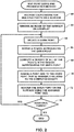
- FIG. 2 is a flow diagram that schematically illustrates a method of generating map 46, in accordance with an embodiment of the present invention
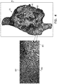
- Figure 3 is a schematic pictorial illustration of the map comprising map points 80 having different respective density-based sizes, in accordance with a first embodiment of the present invention.
- processor 42 receives coordinates (i.e., in coordinate system 54) for multiple map points 80 on a surface such as tissue in heart 26, and in a first rendering step 62, the processor renders, in map 46 (i.e., on display 48), surface 82 ( Figure 3 ) based on the received map point coordinates.
- surface 82 comprises a two-dimensional (2D) surface, such as a 2D scatter plot.
- surface 82 comprises a three-dimensional (3D) surface, such as intracardiac tissue in heart 26.
- An example of an algorithm that processor 42 can use to render surface 82 is described in " The Ball-Pivoting Algorithm for Surface Reconstruction” (Bernardini et al, IEEE Transactions on Visualization and Computer Graphics, Volume 5 Issue 4, October 1999, Pages 349-359 ), which is incorporated herein by reference.
- the ball pivoting algorithm computes a triangle mesh by creating a set of triangles that use map points 80 as vertices of the triangles. Processor 42 then covers the mesh, using any convenient method known in the art, to produce surface 82.
- processor 42 selects a given map point 80, and in a definition step 66, the processor defines a region 84 that surrounds the given point.
- regions 84 can be differentiated by appending a letter to the identifying numeral so that the regions comprise regions 84A-84D.
- the regions are spheres (e.g., spherical regions presented as two-dimensional circles in Figure 3 ), and processor 42 defines a given region 84 (e.g., region 84D in Figure 3 ) around a given map point 80 by defining, in coordinate system 54, a three-dimensional sphere comprising a center corresponding to the coordinates of the given mapping point and a radius 88 having a specified length.
- processor 42 can define the spheres with a radius having a specific length.
- the radius can be a fixed length between 10 and 20 millimeters.
- processor 42 can vary the radius based on the density of the map points near the center of the sphere.
- processor 42 can determine the geodesic distance to the closest point 80 (i.e., from the center). In this embodiment, the density is directly related to the distance from the center of the sphere to the closest point.
- processor 42 computes a density of the points within the given region, and in an assignment step 70, the processor assigns, to the given point, a point size that is inversely related to the computed density. In other words, processor 42 will assign smaller point sizes to the points in the regions having higher densities, and the processor will assign larger point sizes to the points in the regions having lower densities.
- processor 42 computes a given density for a given region 84 based on (e.g., by counting) a number of map points 80 within the given region.
- the computed density for the given map point in a given region 84 is directly related to the number of the map points in the given region (i.e., the regions having higher numbers of mapping points have higher densities and the regions having fewer number of mapping points have lower densities).
- processor 42 computes respective distances 86 between pairs of map points 80, and processor 42 computes the density for a first given map point 80 by identifying a closest second given map point 80.
- the computed density is inversely related to the distance between the first and the second given map points (i.e., longer distances indicate lower densities and shorter distances indicate higher densities).
- processor 42 renders, typically by superimposing, in map 46, the given map point on surface 82.
- processor 42 can present, on display 48, the given map point with its respective size at a location on surface 82 corresponding to the respective coordinates of the given map point.
- processor 42 renders map points 80 by presenting the map points as circular/oval shapes in map 46 on display 48.
- map points 80 can be differentiated by appending a letter to the identifying numeral so that the map points comprise map points 80A-80C.
- map 46 In this example of map 46:
- Figure 4 is a schematic pictorial illustration of the map comprising map points 80 having different respective density-based sizes, in accordance with a second embodiment of the present invention.
- processor 42 presents map points 80 as three-pointed stars having different sizes based on the respective densities of the regions containing the map points.
- the map points can be differentiated by appending a letter to the identifying numeral so that the map points comprise map points 80D-80F. As shown in Figure 4 :
- processor 42 can define a base diameter (or radius) for map points 80, and assign respective multiples of the base diameter each of the map points. Referring to the example shown in Figure 4 , processor 42 can present map point 80F as a star with the base diameter, present map point 80E as a star with 75% of the base diameter, and map point 80D as a star with 50% of the base diameter. Therefore, as medical professional selects different zoom levels, processor 42 can present map points 80 with different diameters, but maintain the proportional lengths of the respective diameters of the map points.
- processor 42 can use other types of visual effects to present map points 80 in regions 84 having different densities.
- processor 42 can define multiple visual effects, assign each of the visual effects to a respective range of the densities, and render, on display 48, points 80 (i.e., on map 46) with respective visual effects that are based on the respective computed densities.
- processor 42 can use different colors to present map points 80. For example, processor 42 can present blue map points 80 in a dense region 84, and present red map points 80 in a sparse region 84.
- processor 42 can use different shapes to present map points 80. For example, processor 42 can present triangle-shaped map points 80 in a dense region 84, and present square-shaped map points 80 in a sparse region 84.
- processor 42 can use different visual effects when presenting map points 80. For example, processor 42 can present non-blinking map points 80 in a dense region 84, and present blinking map points 80 in a sparse region 84.
- step 74 if there are additional map points 80 that have not been sized and rendered, then the method continues with step 64. The method ends when all map points 80 have been sized and rendered using embodiments described hereinabove.
Landscapes
- Health & Medical Sciences (AREA)
- Engineering & Computer Science (AREA)
- Life Sciences & Earth Sciences (AREA)
- Surgery (AREA)
- Physics & Mathematics (AREA)
- Veterinary Medicine (AREA)
- Molecular Biology (AREA)
- Public Health (AREA)
- General Health & Medical Sciences (AREA)
- Biomedical Technology (AREA)
- Heart & Thoracic Surgery (AREA)
- Medical Informatics (AREA)
- Animal Behavior & Ethology (AREA)
- Pathology (AREA)
- Nuclear Medicine, Radiotherapy & Molecular Imaging (AREA)
- Theoretical Computer Science (AREA)
- General Physics & Mathematics (AREA)
- Biophysics (AREA)
- Software Systems (AREA)
- Computer Graphics (AREA)
- Cardiology (AREA)
- Oral & Maxillofacial Surgery (AREA)
- Robotics (AREA)
- Geometry (AREA)
- General Engineering & Computer Science (AREA)
- Computer Hardware Design (AREA)
- Architecture (AREA)
- Gynecology & Obstetrics (AREA)
- Radiology & Medical Imaging (AREA)
- Human Computer Interaction (AREA)
- Measuring And Recording Apparatus For Diagnosis (AREA)
- Endoscopes (AREA)
- Image Generation (AREA)
- Magnetic Resonance Imaging Apparatus (AREA)
Abstract
Description
- The present invention relates generally to image presentation, and specifically to presenting an image of a surface comprising multiple mapping points.
- Some medical procedures include mapping a cavity of a body organ such as a heart. To map the cavity, an operator positions a medical probe at specific locations within the organ, and the probe measures and conveys location information to a mapping system. The mapping system generates a map comprising the measured locations in the organ. The map can be used in applying various diagnostic and therapeutic procedures to the organ.
-
U.S. Patent 6,975,335 to Watenabe describes a method for displaying magnified and reduced areas. The method includes changing pattern densities of areas in an image in order to enable easy detection of magnified and/or reduced areas. For example, when a first given area is magnified and displayed, and a second given area is reduced as a result, a pattern of the first given area is magnified and displayed while a pattern of the second given area is reduced and displayed with respect to the other portions of the image. -
U.S. Patent 7,046,247 to Hao et al. , describes a method for visualizing graphical data sets having a non-uniform graphical density for display. The method includes determining graphical densities of regions and presenting regions having higher graphical densities at higher resolutions. -
Chapter 28 in the Handbook of Computational Statistics: Concepts and Methods (Gentle, James et al., Springer, 2012) includes a description of a method for presenting data points plotted in a graph. The method includes increasing a brightness parameter for data points in areas with relatively high overplotting (i.e., areas comprising high densities of data points). -
U.S. Patent 9,323,413 to Baar et al. -
U.S. Patent 9,299,186 to Shoemaker et al. -
U.S. Patent 6,263,287 to Zhen et al. , describes a method for manipulating and analyzing gene expression data. The method includes graphical tools, and uses a clustering algorithm to correlate temporal patterns of gene expression. - The description above is presented as a general overview of related art in this field and should not be construed as an admission that any of the information it contains constitutes prior art against the present patent application.
- Documents incorporated by reference in the present patent application are to be considered an integral part of the application except that to the extent any terms are defined in these incorporated documents in a manner that conflicts with the definitions made explicitly or implicitly in the present specification, only the definitions in the present specification should be considered.
- There is provided, in accordance with an embodiment of the present invention, a method, including receiving, by a processor, respective coordinates for multiple points on a surface, rendering an image of the surface on a display screen, and for each given point among the multiple points, computing a density of the points within a region surrounding the given point, and rendering, on the display screen, the given point on the surface with a point size that is inversely related to the computed density.
- In some embodiments, computing the density of the points within the region surrounding the given point includes counting a number of the points within the region. In other embodiments, computing the density of the given point within the region includes identifying, from the multiple points, a further point that is closest to the given point, and determining a distance between the given point and the further point.
- In additional embodiments, the surface comprises a two-dimensional surface or a three-dimensional surface. In further embodiments, the three-dimensional surface is representative of tissue in a body cavity, and wherein receiving the respective coordinates comprises receiving the respective coordinates from a medical probe inserted into the body cavity. In supplemental embodiments, the body cavity includes a heart, wherein the tissue comprises intracardiac tissue, and wherein the medical probe comprises an intracardiac catheter.
- In some embodiments, rendering the given point includes presenting, on the display, the given point using a shape selected from a group consisting of a circle, an oval and a star. In additional embodiments, computing the density of the points within the region surrounding the given point includes defining each given region as a sphere comprising a center having a center corresponding to the coordinates of the given point and a radius having a specified length. In further embodiments, the method includes defining multiple visual effects, assigning each of the visual effects to a respective range of the densities, and rendering, on the display, the given point on the surface with a given visual effect that is based on the computed density.
- There is also provided, in accordance with an embodiment of the present invention, an apparatus, including a display screen, and a processor configured to receive respective coordinates for multiple points on a surface, to render an image of the surface on the display screen, and for each given point among the multiple points, to compute a density of the points within a region surrounding the given point, and to render, on the display screen, the given point on the surface with a point size that is inversely related to the computed density.
- There is further provided, in accordance with an embodiment of the present invention, a computer software product the product including a non-transitory computer-readable medium, in which program instructions are stored, which instructions, when read by a computer, cause the computer to receive respective coordinates for multiple points on a surface, to render an image of the surface on a display screen, and for each given point among the multiple points, to compute a density of the points within a region surrounding the given point, and to render, on the display screen, the given point on the surface with a point size that is inversely related to the computed density.
- The disclosure is herein described, by way of example only, with reference to the accompanying drawings, wherein:
-
Figure 1 is a schematic pictorial illustrations of a medical system configured to adjust sizes of points in a map based on densities of regions in the map including the points, in accordance with an embodiment of the present invention; -
Figure 2 is a flow diagram that schematically illustrates a method of presenting the map comprising points having different sizes, in accordance with an embodiment of the present invention; -
Figure 3 is a schematic pictorial illustration showing a section of the map that includes some of the points having different sizes, in accordance with a first embodiment of the present invention; and -
Figure 4 is a schematic pictorial illustration showing a section of the map that includes some of the points having different sizes, in accordance with a second embodiment of the present invention. - Anatomical mapping procedures typically create a map comprising map points collected from a mapping system. Each map point (also referred to herein simply as a point) comprises a respective coordinate within a body cavity, and possibly a physiological property collected by a medical probe at the respective coordinate. While collecting the map points, some of the points may be close to each other, defining dense regions. Other points may be far from all other points, and these points are assumed to define sparse regions. While a user typically wants to reduce or eliminate sparse regions while mapping a body cavity, it may be difficult for the user to identify the sparse regions while performing the procedure.
- As described supra, a dense region comprises map points that are close to one another. If the map points in a dense region are presented using the same size, it may be difficult for a user to differentiate between them, especially if there are overlapping and/or completely hidden map points. Therefore, it may be difficult for a user to identify a specific map point in a dense region.
- Embodiments of the present invention provide methods and systems for emphasizing points in sparse regions while mapping a body cavity such as a heart. As described hereinbelow, respective coordinates are received for multiple points on a surface, and an image of the surface is rendered on a display screen. For each given point among the multiple points, a density of the points within a region surrounding the given point is computed, wherein the given point on the surface is rendered with a point size that is inversely related to the computed density.
- By rendering points with point sizes that are inversely related to the densities of their respective regions, systems implementing embodiments of the present invention can present larger-sized points in sparse regions, and can present smaller-sized points in dense regions. Consequently, points defining sparse regions can be emphasized (i.e., by their larger-sized points), thereby enabling a user to easily identify any sparse regions in the map. Likewise, using smaller sizes to present map points in a dense region enables a user to easily distinguish between the individual map points in the region.
-
Figure 1 is a schematic, pictorial illustration of a medical system 20 comprising amedical probe 22 and acontrol console 24, in accordance with an embodiment of the present invention. Medical system 20 may be based, for example, on the CARTO® system, produced by Biosense Webster Inc. (33 Technology Drive, Irvine, CA 92618). In embodiments described hereinbelow,medical probe 22 comprises an intracardiac catheter that is used for mapping aheart 26 of apatient 28. Alternatively,medical probe 22 may be used, mutatis mutandis, for other therapeutic and/or diagnostic purposes in the heart or in other body organs. - During a medical procedure, a
medical professional 30 insertsmedical probe 22 into a biocompatible sheath (not shown) that has been pre-positioned in a body cavity (e.g., a chamber of heart 26) of the patient so that adistal end 32 of the medical probe enters the body cavity. In the configuration shown inFigure 1 , aprobe electrode 34 is mounted on adistal tip 36 ofmedical probe 22. The probe electrode typically comprises a thin metal layer formed overdistal tip 36. In some embodiments,distal end 32 may have other electrodes that are insulated from each other and fromelectrode 34, which for simplicity are not shown in the diagram.Electrode 34 is connected to control console by conductors inprobe 22, not shown in the figures. - In embodiments described herein,
electrode 34 can be used to determine a location ofdistal tip 36 inheart 26. In additional embodiments,electrode 34 can also be used to measure a certain physiological property (e.g., the local surface electrical potential) at multiple locations inheart 26. -
Control console 24 is connected, by acable 38, to body surface electrodes, which typically compriseadhesive skin patches 40 that are affixed topatient 28.Control console 24 comprises aprocessor 42 that can determine position coordinates ofdistal tip 36 insideheart 26 based on impedances measured betweenadhesive skin patches 40 andprobe electrode 34. - To determine the position of
distal tip 36,control console 24 can convey a current to electrode 34, andprocessor 42 receives signals indicating respective impedances that are detected bypatches 40 in response to the conveyed current. Based on the impedances,processor 42 can determine a 3D location of electrode 34 (i.e., with respect to patches 40) in a coordinatesystem 54 comprising anX-axis 55, a Y-axis 56 and a Z-axis 58. Impedance-based position tracking techniques are described, for example, inU.S. Patents 5,983,126 ,6,456,864 and5,944,022 , whose disclosures are incorporated herein by reference. - Although the medical system shown in
Figures 1 and2 uses impedance-based sensing to measure a location ofdistal tip 36, other position tracking techniques may be used (e.g., techniques using magnetic-based sensors). In systems using magnetic-based sensors,distal end 32 comprises a magnetic field sensor (not shown) typically comprising a set of three orthogonal sensor coils, and generator coils (not shown) are placed below the patient at known positions external topatient 28. The generator coils transmit alternating magnetic fields into a region withinpatient 28, the alternating magnetic fields induce signals in the magnetic field sensor, andprocessor 42 analyzes these signals to derive the location and orientation of the magnetic field sensor with respect to the field generator coils. - Magnetic position tracking techniques are described, for example, in
U.S. Patents 5,391,199 ,5,443,489 ,6,788,967 ,6,690,963 ,5,558,091 ,6,172,499 6,177,792 , whose disclosures are incorporated herein by reference. The methods of position sensing described hereinabove are implemented in the above-mentioned CARTO® system and are described in detail in the patents cited above. -
Processor 42 typically comprises a general-purpose computer, with suitable front end and interface circuits for receiving signals from elements of medical probe 22 (e.g., probe electrode 34) and controlling the other components ofcontrol console 24.Processor 42 may be programmed in software to carry out the functions that are described herein. The software may be downloaded to controlconsole 24 in electronic form, over a network, for example, or it may be provided on non-transitory tangible media, such as optical, magnetic or electronic memory media. Alternatively, some or all of the functions ofprocessor 42 may be carried out by dedicated or programmable digital hardware components. -
Control console 24 also comprises an input/output (I/O)communications interface 44 that enables the control console to transfer signals from, and/or transfer signals to probeelectrode 34 andadhesive skin patches 40.Probe electrode 34, andprocessor 42 are all coupled to I/O communications interface 44 via wired connections (not shown) and/or wireless connections. - Based on impedances derived from signals received from
probe electrode 34 andadhesive skin patches 40,processor 42 can generate amap 46 comprises multiple map points, with each map point comprising coordinates on an inner chamber surface ofheart 26. During the procedure,processor 42 can presentmap 46 to medical professional 30 on adisplay screen 48, and store data representing the map in amemory 50.Memory 50 may comprise any suitable volatile and/or non-volatile memory, such as random access memory or a hard disk drive. - In some embodiments, medical professional 30 can manipulate map 46 using one or
more input devices 52. In alternative embodiments,display 48 may comprise a touchscreen that can be configured to accept inputs from medical professional 30, in addition to presentingmap 46. -
Figure 2 is a flow diagram that schematically illustrates a method of generatingmap 46, in accordance with an embodiment of the present invention, andFigure 3 is a schematic pictorial illustration of the map comprising map points 80 having different respective density-based sizes, in accordance with a first embodiment of the present invention. In a receivestep 60,processor 42 receives coordinates (i.e., in coordinate system 54) for multiple map points 80 on a surface such as tissue inheart 26, and in afirst rendering step 62, the processor renders, in map 46 (i.e., on display 48), surface 82 (Figure 3 ) based on the received map point coordinates. - In one embodiment,
surface 82 comprises a two-dimensional (2D) surface, such as a 2D scatter plot. In another embodiment,surface 82 comprises a three-dimensional (3D) surface, such as intracardiac tissue inheart 26. An example of an algorithm thatprocessor 42 can use to rendersurface 82 is described in "The Ball-Pivoting Algorithm for Surface Reconstruction" (Bernardini et al, IEEE Transactions on Visualization and Computer Graphics, Volume 5 Issue 4, October 1999, Pages 349-359), which is incorporated herein by reference. As described in the research paper, the ball pivoting algorithm computes a triangle mesh by creating a set of triangles that use map points 80 as vertices of the triangles.Processor 42 then covers the mesh, using any convenient method known in the art, to producesurface 82. - In a
selection step 64,processor 42 selects a givenmap point 80, and in adefinition step 66, the processor defines a region 84 that surrounds the given point. InFigure 3 , regions 84 can be differentiated by appending a letter to the identifying numeral so that the regions compriseregions 84A-84D. In some embodiments, the regions are spheres (e.g., spherical regions presented as two-dimensional circles inFigure 3 ), andprocessor 42 defines a given region 84 (e.g.,region 84D inFigure 3 ) around a givenmap point 80 by defining, in coordinatesystem 54, a three-dimensional sphere comprising a center corresponding to the coordinates of the given mapping point and a radius 88 having a specified length. - In one embodiment,
processor 42 can define the spheres with a radius having a specific length. For example, the radius can be a fixed length between 10 and 20 millimeters. In another embodiment,processor 42 can vary the radius based on the density of the map points near the center of the sphere. For example,processor 42 can determine the geodesic distance to the closest point 80 (i.e., from the center). In this embodiment, the density is directly related to the distance from the center of the sphere to the closest point. - In a
computation step 68,processor 42 computes a density of the points within the given region, and in anassignment step 70, the processor assigns, to the given point, a point size that is inversely related to the computed density. In other words,processor 42 will assign smaller point sizes to the points in the regions having higher densities, and the processor will assign larger point sizes to the points in the regions having lower densities. - In a first embodiment,
processor 42 computes a given density for a given region 84 based on (e.g., by counting) a number of map points 80 within the given region. In the first embodiment, the computed density for the given map point in a given region 84 is directly related to the number of the map points in the given region (i.e., the regions having higher numbers of mapping points have higher densities and the regions having fewer number of mapping points have lower densities). - In a second embodiment,
processor 42 computesrespective distances 86 between pairs of map points 80, andprocessor 42 computes the density for a first givenmap point 80 by identifying a closest second givenmap point 80. In the second embodiment, the computed density is inversely related to the distance between the first and the second given map points (i.e., longer distances indicate lower densities and shorter distances indicate higher densities). - In a
second rendering step 72,processor 42 renders, typically by superimposing, inmap 46, the given map point onsurface 82. To render the given map point onsurface 82,processor 42 can present, ondisplay 48, the given map point with its respective size at a location onsurface 82 corresponding to the respective coordinates of the given map point. In the embodiment presented inFigure 3 ,processor 42 renders map points 80 by presenting the map points as circular/oval shapes inmap 46 ondisplay 48. - In
Figure 3 , map points 80 can be differentiated by appending a letter to the identifying numeral so that the map points comprise map points 80A-80C. In this example of map 46: -
Region 84A has a high density andprocessor 42 rendersmap point 80A using a small sized circle. -
Region 84C has a low density andprocessor 42 rendersmap point 80C using a large sized circle. -
Region 84B has a medium density (i.e., between the low and the high densities), andprocessor 42 rendersmap point 80B using a medium sized circle (i.e., having a diameter between the diameter of the small and the diameter of the large sized circles). -
Figure 4 is a schematic pictorial illustration of the map comprising map points 80 having different respective density-based sizes, in accordance with a second embodiment of the present invention. In the second embodiment,processor 42 presents mappoints 80 as three-pointed stars having different sizes based on the respective densities of the regions containing the map points. - In the example shown in
Figure 4 , the map points can be differentiated by appending a letter to the identifying numeral so that the map points comprise map points 80D-80F. As shown inFigure 4 : -
Processor 42 rendersmap point 80D using a small sized star. -
Processor 42 rendersmap point 80F using a large sized star. -
Processor 42 rendersmap point 80E using a medium sized star (i.e., between the small and the large sized stars). - During a medical procedure, medical professional 30 can manipulate
input devices 50 in order to set zoom levels formap 46 ondisplay 48, thereby changing the sizes of map points 80 on the display. In some embodiments,processor 42 can define a base diameter (or radius) for map points 80, and assign respective multiples of the base diameter each of the map points. Referring to the example shown inFigure 4 ,processor 42 can presentmap point 80F as a star with the base diameter,present map point 80E as a star with 75% of the base diameter, andmap point 80D as a star with 50% of the base diameter. Therefore, as medical professional selects different zoom levels,processor 42 can present map points 80 with different diameters, but maintain the proportional lengths of the respective diameters of the map points. - In addition to presenting map points 80 as different sized ovals/circles and stars,
processor 42 can use other types of visual effects to present map points 80 in regions 84 having different densities. To present map points 80 in regions 84 having different densities,processor 42 can define multiple visual effects, assign each of the visual effects to a respective range of the densities, and render, ondisplay 48, points 80 (i.e., on map 46) with respective visual effects that are based on the respective computed densities. - In a first embodiment,
processor 42 can use different colors to present map points 80. For example,processor 42 can present blue map points 80 in a dense region 84, and present red map points 80 in a sparse region 84. In a second embodiment,processor 42 can use different shapes to present map points 80. For example,processor 42 can present triangle-shaped map points 80 in a dense region 84, and present square-shaped map points 80 in a sparse region 84. In a third embodiment,processor 42 can use different visual effects when presenting map points 80. For example,processor 42 can present non-blinking map points 80 in a dense region 84, and present blinking map points 80 in a sparse region 84. - In a
comparison step 74, if there are additional map points 80 that have not been sized and rendered, then the method continues withstep 64. The method ends when all mappoints 80 have been sized and rendered using embodiments described hereinabove. - It will be appreciated that the embodiments described above are cited by way of example, and that the present invention is not limited to what has been particularly shown and described hereinabove. Rather, the scope of the present invention includes both combinations and subcombinations of the various features described hereinabove, as well as variations and modifications thereof which would occur to persons skilled in the art upon reading the foregoing description and which are not disclosed in the prior art.
-
- 1. A method, comprising:
- receiving, by a processor, respective coordinates for multiple points on a surface;
- rendering an image of the surface on a display screen; and
- for each given point among the multiple points, computing a density of the points within a region surrounding the given point, and rendering, on the display screen, the given point on the surface with a point size that is inversely related to the computed density.
- 2. The method according to aspect 1, wherein computing the density of the points within the region surrounding the given point comprises counting a number of the points within the region.
- 3. The method according to aspect 1 wherein computing the density of the given point within the region comprises identifying, from the multiple points, a further point that is closest to the given point, and determining a distance between the given point and the further point.
- 4. The method according to aspect 1, wherein the surface comprises a two-dimensional surface or a three-dimensional surface.
- 5. The method according to aspect 4, wherein the three-dimensional surface is representative of tissue in a body cavity, and wherein receiving the respective coordinates comprises receiving the respective coordinates from a medical probe inserted into the body cavity.
- 6. The method according to aspect 5, wherein the body cavity comprises a heart, wherein the tissue comprises intracardiac tissue, and wherein the medical probe comprises an intracardiac catheter.
- 7. The method according to aspect 1, wherein rendering the given point comprises presenting, on the display, the given point using a shape selected from a group consisting of a circle, an oval and a star.
- 8. The method according to aspect 1, wherein computing the density of the points within the region surrounding the given point comprises defining each given region as a sphere comprising a center having a center corresponding to the coordinates of the given point and a radius having a specified length.
- 9. The method according to aspect 1, and comprising defining multiple visual effects, assigning each of the visual effects to a respective range of the densities, and rendering, on the display, the given point on the surface with a given visual effect that is based on the computed density.
Claims (16)
- A method, comprising:receiving, by a processor, respective coordinates for multiple points on a surface;rendering an image of the surface on a display screen; andfor each given point among the multiple points, computing a density of the points within a region surrounding the given point, and rendering, on the display screen, the given point on the surface with a point size that is inversely related to the computed density.
- The method according to claim 1, wherein computing the density of the points within the region surrounding the given point comprises counting a number of the points within the region.
- The method according to claim 1 wherein computing the density of the given point within the region comprises identifying, from the multiple points, a further point that is closest to the given point, and determining a distance between the given point and the further point.
- The method according to claim 1, wherein rendering the given point comprises presenting, on the display, the given point using a shape selected from a group consisting of a circle, an oval and a star.
- The method according to claim 1, wherein computing the density of the points within the region surrounding the given point comprises defining each given region as a sphere comprising a center having a center corresponding to the coordinates of the given point and a radius having a specified length.
- The method according to claim 1, and comprising defining multiple visual effects, assigning each of the visual effects to a respective range of the densities, and rendering, on the display, the given point on the surface with a given visual effect that is based on the computed density.
- An apparatus, comprising:a display screen; anda processor configured:to receive respective coordinates for multiple points on a surface,to render an image of the surface on the display screen, andfor each given point among the multiple points, to compute a density of the points within a region surrounding the given point, and to render, on the display screen, the given point on the surface with a point size that is inversely related to the computed density.
- The apparatus according to claim 7, wherein the processor is configured to compute the density of the points within the region surrounding the given point by counting a number of the points within the region.
- The apparatus according to claim 7, wherein the processor is configured to compute the density of the given point within the region by identifying, from the multiple points, a further point that is closest to the given point, and determining a distance between the given point and the further point.
- The method according to claim 1 or the apparatus according to claim 7, wherein the surface comprises a two-dimensional surface or a three-dimensional surface.
- The apparatus according to claim 10, wherein the three-dimensional surface is representative of tissue in a body cavity, and wherein the processor is configured to receive the respective coordinates by receiving the respective coordinates from a medical probe inserted into the body cavity.
- The apparatus according to claim 11, wherein the body cavity comprises a heart, wherein the tissue comprises intracardiac tissue, and wherein the medical probe comprises an intracardiac catheter.
- The apparatus according to claim 7, wherein the processor is configured to render the given point by presenting, on the display, the given point using a shape selected from a group consisting of a circle, an oval and a star.
- The apparatus according to claim 7, wherein the processor is configured to compute the density of the points within the region surrounding the given point by defining each given region as a sphere comprising a center having a center corresponding to the coordinates of the given point and a radius having a specified length.
- The apparatus according to claim 7, wherein the processor is configured to define multiple visual effects, to assign each of the visual effects to a respective range of the densities, and to render, on the display, the given point on the surface with a given visual effect that is based on the computed density.
- A computer software product, the product comprising a non-transitory computer-readable medium, in which program instructions are stored, which instructions, when read by a computer, cause the computer:to receive respective coordinates for multiple points on a surface;to render an image of the surface on a display screen; andfor each given point among the multiple points, to compute a density of the points within a region surrounding the given point, and to render, on the display screen, the given point on the surface with a point size that is inversely related to the computed density.
Applications Claiming Priority (1)
| Application Number | Priority Date | Filing Date | Title |
|---|---|---|---|
| US15/822,380 US10463445B2 (en) | 2017-11-27 | 2017-11-27 | Point density illustration |
Publications (2)
| Publication Number | Publication Date |
|---|---|
| EP3489905A1 true EP3489905A1 (en) | 2019-05-29 |
| EP3489905B1 EP3489905B1 (en) | 2021-08-04 |
Family
ID=64572086
Family Applications (1)
| Application Number | Title | Priority Date | Filing Date |
|---|---|---|---|
| EP18208351.9A Active EP3489905B1 (en) | 2017-11-27 | 2018-11-26 | Point density illustration |
Country Status (7)
| Country | Link |
|---|---|
| US (1) | US10463445B2 (en) |
| EP (1) | EP3489905B1 (en) |
| JP (1) | JP7370699B2 (en) |
| CN (1) | CN110013308B (en) |
| AU (1) | AU2018250526A1 (en) |
| CA (1) | CA3024441A1 (en) |
| IL (1) | IL262601B (en) |
Families Citing this family (1)
| Publication number | Priority date | Publication date | Assignee | Title |
|---|---|---|---|---|
| KR102271189B1 (en) * | 2019-12-11 | 2021-06-30 | 성균관대학교산학협력단 | Methods and apparatuses for improving surface point cluster in surgical navigation system |
Citations (16)
| Publication number | Priority date | Publication date | Assignee | Title |
|---|---|---|---|---|
| US5391199A (en) | 1993-07-20 | 1995-02-21 | Biosense, Inc. | Apparatus and method for treating cardiac arrhythmias |
| US5558091A (en) | 1993-10-06 | 1996-09-24 | Biosense, Inc. | Magnetic determination of position and orientation |
| US5944022A (en) | 1997-04-28 | 1999-08-31 | American Cardiac Ablation Co. Inc. | Catheter positioning system |
| US5983126A (en) | 1995-11-22 | 1999-11-09 | Medtronic, Inc. | Catheter location system and method |
| US6172499B1 (en) | 1999-10-29 | 2001-01-09 | Ascension Technology Corporation | Eddy current error-reduced AC magnetic position measurement system |
| US6177792B1 (en) | 1996-03-26 | 2001-01-23 | Bisense, Inc. | Mutual induction correction for radiator coils of an objects tracking system |
| US6263287B1 (en) | 1998-11-12 | 2001-07-17 | Scios Inc. | Systems for the analysis of gene expression data |
| US6456864B1 (en) | 1994-10-11 | 2002-09-24 | Ep Technologies, Inc. | Systems and methods for guiding movable electrode elements within multiple-electrode structures |
| US6690963B2 (en) | 1995-01-24 | 2004-02-10 | Biosense, Inc. | System for determining the location and orientation of an invasive medical instrument |
| US6975335B2 (en) | 1999-12-28 | 2005-12-13 | International Business Machines Corporation | Method of displaying magnified and reduced areas and apparatus thereof |
| US7046247B2 (en) | 2002-05-15 | 2006-05-16 | Hewlett-Packard Development Company, L.P. | Method for visualizing graphical data sets having a non-uniform graphical density for display |
| WO2007035306A2 (en) * | 2005-09-15 | 2007-03-29 | St. Jude Medical, Atrial Fibrillation Division, Inc. | System and method for three-dimensional mapping of electrophysiology information |
| EP2395481A2 (en) * | 2010-06-10 | 2011-12-14 | Biosense Webster (Israel), Ltd | Operator-controlled map point density |
| EP2837328A1 (en) * | 2013-08-12 | 2015-02-18 | Biosense Webster (Israel), Ltd. | Unmapped region visualization |
| US9299186B2 (en) | 2004-09-03 | 2016-03-29 | Callahan Cellular L.L.C. | Occlusion reduction and magnification for multidimensional data presentations |
| US9323413B2 (en) | 2001-06-12 | 2016-04-26 | Callahan Cellular L.L.C. | Graphical user interface with zoom for detail-in-context presentations |
Family Cites Families (13)
| Publication number | Priority date | Publication date | Assignee | Title |
|---|---|---|---|---|
| US6301496B1 (en) | 1998-07-24 | 2001-10-09 | Biosense, Inc. | Vector mapping of three-dimensionally reconstructed intrabody organs and method of display |
| US6226542B1 (en) * | 1998-07-24 | 2001-05-01 | Biosense, Inc. | Three-dimensional reconstruction of intrabody organs |
| US6907281B2 (en) * | 2000-09-07 | 2005-06-14 | Ge Medical Systems | Fast mapping of volumetric density data onto a two-dimensional screen |
| JP4504114B2 (en) | 2004-06-23 | 2010-07-14 | オリンパス株式会社 | Ultrasound diagnostic imaging equipment |
| FR2948475A1 (en) * | 2009-07-24 | 2011-01-28 | Bionext | METHOD FOR CHARACTERIZING THREE DIMENSIONAL OBJECTS |
| CN101853485A (en) * | 2010-06-04 | 2010-10-06 | 浙江工业大学 | A Simplified Processing Method for Non-uniform Point Clouds Based on Neighbor Propagation Clustering |
| AU2012225250B2 (en) * | 2011-03-10 | 2016-12-08 | Enchannel Medical, Ltd. | Device and method for the geometric determination of electrical dipole densities on the cardiac wall |
| GB2518171A (en) * | 2013-09-11 | 2015-03-18 | Epistemy Ltd | Improvements in or relating to data processing |
| US9865086B2 (en) * | 2014-03-21 | 2018-01-09 | St. Jude Medical, Cardiololgy Division, Inc. | Methods and systems for generating a multi-dimensional surface model of a geometric structure |
| JP6311404B2 (en) | 2014-03-31 | 2018-04-18 | 富士通株式会社 | Management program, management apparatus, and management method |
| JP6359868B2 (en) | 2014-04-25 | 2018-07-18 | 東芝プラントシステム株式会社 | 3D data display device, 3D data display method, and 3D data display program |
| CN106250080A (en) * | 2016-07-29 | 2016-12-21 | 腾讯科技(深圳)有限公司 | Image display method and device |
| US10806503B2 (en) * | 2017-02-06 | 2020-10-20 | General Electric Company | Methods and systems for electrophysiology ablation gap analysis |
-
2017
- 2017-11-27 US US15/822,380 patent/US10463445B2/en active Active
-
2018
- 2018-10-22 AU AU2018250526A patent/AU2018250526A1/en not_active Abandoned
- 2018-10-25 IL IL262601A patent/IL262601B/en unknown
- 2018-11-16 CA CA3024441A patent/CA3024441A1/en not_active Abandoned
- 2018-11-26 EP EP18208351.9A patent/EP3489905B1/en active Active
- 2018-11-26 JP JP2018220029A patent/JP7370699B2/en active Active
- 2018-11-27 CN CN201811424488.5A patent/CN110013308B/en active Active
Patent Citations (18)
| Publication number | Priority date | Publication date | Assignee | Title |
|---|---|---|---|---|
| US5443489A (en) | 1993-07-20 | 1995-08-22 | Biosense, Inc. | Apparatus and method for ablation |
| US5391199A (en) | 1993-07-20 | 1995-02-21 | Biosense, Inc. | Apparatus and method for treating cardiac arrhythmias |
| US5558091A (en) | 1993-10-06 | 1996-09-24 | Biosense, Inc. | Magnetic determination of position and orientation |
| US6456864B1 (en) | 1994-10-11 | 2002-09-24 | Ep Technologies, Inc. | Systems and methods for guiding movable electrode elements within multiple-electrode structures |
| US6690963B2 (en) | 1995-01-24 | 2004-02-10 | Biosense, Inc. | System for determining the location and orientation of an invasive medical instrument |
| US5983126A (en) | 1995-11-22 | 1999-11-09 | Medtronic, Inc. | Catheter location system and method |
| US6177792B1 (en) | 1996-03-26 | 2001-01-23 | Bisense, Inc. | Mutual induction correction for radiator coils of an objects tracking system |
| US5944022A (en) | 1997-04-28 | 1999-08-31 | American Cardiac Ablation Co. Inc. | Catheter positioning system |
| US6788967B2 (en) | 1997-05-14 | 2004-09-07 | Biosense, Inc. | Medical diagnosis, treatment and imaging systems |
| US6263287B1 (en) | 1998-11-12 | 2001-07-17 | Scios Inc. | Systems for the analysis of gene expression data |
| US6172499B1 (en) | 1999-10-29 | 2001-01-09 | Ascension Technology Corporation | Eddy current error-reduced AC magnetic position measurement system |
| US6975335B2 (en) | 1999-12-28 | 2005-12-13 | International Business Machines Corporation | Method of displaying magnified and reduced areas and apparatus thereof |
| US9323413B2 (en) | 2001-06-12 | 2016-04-26 | Callahan Cellular L.L.C. | Graphical user interface with zoom for detail-in-context presentations |
| US7046247B2 (en) | 2002-05-15 | 2006-05-16 | Hewlett-Packard Development Company, L.P. | Method for visualizing graphical data sets having a non-uniform graphical density for display |
| US9299186B2 (en) | 2004-09-03 | 2016-03-29 | Callahan Cellular L.L.C. | Occlusion reduction and magnification for multidimensional data presentations |
| WO2007035306A2 (en) * | 2005-09-15 | 2007-03-29 | St. Jude Medical, Atrial Fibrillation Division, Inc. | System and method for three-dimensional mapping of electrophysiology information |
| EP2395481A2 (en) * | 2010-06-10 | 2011-12-14 | Biosense Webster (Israel), Ltd | Operator-controlled map point density |
| EP2837328A1 (en) * | 2013-08-12 | 2015-02-18 | Biosense Webster (Israel), Ltd. | Unmapped region visualization |
Non-Patent Citations (3)
| Title |
|---|
| BERNARDINI ET AL.: "The Ball-Pivoting Algorithm for Surface Reconstruction", IEEE TRANSACTIONS ON VISUALIZATION AND COMPUTER GRAPHICS, vol. 5, no. 4, October 1999 (1999-10-01), pages 349 - 359, XP000908551, DOI: doi:10.1109/2945.817351 |
| GENTLE, JAMES ET AL.: "Handbook of Computational Statistics: Concepts and Methods", 2012, SPRINGER |
| WILSON K ET AL: "Mapping of Cardiac Electrophysiology Onto a Dynamic Patient-Specific Heart Model", IEEE TRANSACTIONS ON MEDICAL IMAGING, IEEE SERVICE CENTER, PISCATAWAY, NJ, US, vol. 28, no. 12, 1 December 2009 (2009-12-01), pages 1870 - 1880, XP011281238, ISSN: 0278-0062, DOI: 10.1109/TMI.2009.2021429 * |
Also Published As
| Publication number | Publication date |
|---|---|
| CA3024441A1 (en) | 2019-05-27 |
| CN110013308B (en) | 2024-08-06 |
| IL262601B (en) | 2021-12-01 |
| EP3489905B1 (en) | 2021-08-04 |
| US10463445B2 (en) | 2019-11-05 |
| JP2019096322A (en) | 2019-06-20 |
| AU2018250526A1 (en) | 2019-06-13 |
| US20190159861A1 (en) | 2019-05-30 |
| CN110013308A (en) | 2019-07-16 |
| JP7370699B2 (en) | 2023-10-30 |
| IL262601A (en) | 2019-03-31 |
Similar Documents
| Publication | Publication Date | Title |
|---|---|---|
| US11324566B2 (en) | Instrument guidance system for sinus surgery | |
| AU2017254839B2 (en) | Selectably transparent electrophysiology map | |
| JP6775939B2 (en) | Differential mapping of body organs | |
| US9940747B2 (en) | Mapping 3D to 2D images | |
| JP7154853B2 (en) | Improving Performance of Impedance-Based Position Tracking Using Scattering Interpolation | |
| CN114246685B (en) | Techniques for guiding reacquiring a registration point on a patient's body | |
| JP2022146920A (en) | Visualizing multiple parameters overlaid on anatomical map | |
| EP3489905B1 (en) | Point density illustration | |
| JP2022117968A (en) | Catheter representation via voxels within organ | |
| CN111631720B (en) | Mapping of the body cavity | |
| US20250225654A1 (en) | Method for displaying a 3d model of a patient | |
| EP4258216A1 (en) | Method for displaying a 3d model of a patient | |
| US11967073B2 (en) | Method for displaying a 3D model of a patient |
Legal Events
| Date | Code | Title | Description |
|---|---|---|---|
| PUAI | Public reference made under article 153(3) epc to a published international application that has entered the european phase |
Free format text: ORIGINAL CODE: 0009012 |
|
| STAA | Information on the status of an ep patent application or granted ep patent |
Free format text: STATUS: THE APPLICATION HAS BEEN PUBLISHED |
|
| AK | Designated contracting states |
Kind code of ref document: A1 Designated state(s): AL AT BE BG CH CY CZ DE DK EE ES FI FR GB GR HR HU IE IS IT LI LT LU LV MC MK MT NL NO PL PT RO RS SE SI SK SM TR |
|
| AX | Request for extension of the european patent |
Extension state: BA ME |
|
| STAA | Information on the status of an ep patent application or granted ep patent |
Free format text: STATUS: REQUEST FOR EXAMINATION WAS MADE |
|
| 17P | Request for examination filed |
Effective date: 20191115 |
|
| RBV | Designated contracting states (corrected) |
Designated state(s): AL AT BE BG CH CY CZ DE DK EE ES FI FR GB GR HR HU IE IS IT LI LT LU LV MC MK MT NL NO PL PT RO RS SE SI SK SM TR |
|
| GRAP | Despatch of communication of intention to grant a patent |
Free format text: ORIGINAL CODE: EPIDOSNIGR1 |
|
| STAA | Information on the status of an ep patent application or granted ep patent |
Free format text: STATUS: GRANT OF PATENT IS INTENDED |
|
| INTG | Intention to grant announced |
Effective date: 20210409 |
|
| GRAJ | Information related to disapproval of communication of intention to grant by the applicant or resumption of examination proceedings by the epo deleted |
Free format text: ORIGINAL CODE: EPIDOSDIGR1 |
|
| STAA | Information on the status of an ep patent application or granted ep patent |
Free format text: STATUS: REQUEST FOR EXAMINATION WAS MADE |
|
| GRAP | Despatch of communication of intention to grant a patent |
Free format text: ORIGINAL CODE: EPIDOSNIGR1 |
|
| STAA | Information on the status of an ep patent application or granted ep patent |
Free format text: STATUS: GRANT OF PATENT IS INTENDED |
|
| INTC | Intention to grant announced (deleted) | ||
| GRAS | Grant fee paid |
Free format text: ORIGINAL CODE: EPIDOSNIGR3 |
|
| INTG | Intention to grant announced |
Effective date: 20210607 |
|
| GRAA | (expected) grant |
Free format text: ORIGINAL CODE: 0009210 |
|
| STAA | Information on the status of an ep patent application or granted ep patent |
Free format text: STATUS: THE PATENT HAS BEEN GRANTED |
|
| AK | Designated contracting states |
Kind code of ref document: B1 Designated state(s): AL AT BE BG CH CY CZ DE DK EE ES FI FR GB GR HR HU IE IS IT LI LT LU LV MC MK MT NL NO PL PT RO RS SE SI SK SM TR |
|
| REG | Reference to a national code |
Ref country code: GB Ref legal event code: FG4D |
|
| REG | Reference to a national code |
Ref country code: AT Ref legal event code: REF Ref document number: 1417780 Country of ref document: AT Kind code of ref document: T Effective date: 20210815 |
|
| REG | Reference to a national code |
Ref country code: CH Ref legal event code: EP |
|
| REG | Reference to a national code |
Ref country code: DE Ref legal event code: R096 Ref document number: 602018021140 Country of ref document: DE |
|
| REG | Reference to a national code |
Ref country code: IE Ref legal event code: FG4D |
|
| REG | Reference to a national code |
Ref country code: NL Ref legal event code: FP |
|
| REG | Reference to a national code |
Ref country code: LT Ref legal event code: MG9D |
|
| REG | Reference to a national code |
Ref country code: AT Ref legal event code: MK05 Ref document number: 1417780 Country of ref document: AT Kind code of ref document: T Effective date: 20210804 |
|
| PG25 | Lapsed in a contracting state [announced via postgrant information from national office to epo] |
Ref country code: RS Free format text: LAPSE BECAUSE OF FAILURE TO SUBMIT A TRANSLATION OF THE DESCRIPTION OR TO PAY THE FEE WITHIN THE PRESCRIBED TIME-LIMIT Effective date: 20210804 Ref country code: SE Free format text: LAPSE BECAUSE OF FAILURE TO SUBMIT A TRANSLATION OF THE DESCRIPTION OR TO PAY THE FEE WITHIN THE PRESCRIBED TIME-LIMIT Effective date: 20210804 Ref country code: HR Free format text: LAPSE BECAUSE OF FAILURE TO SUBMIT A TRANSLATION OF THE DESCRIPTION OR TO PAY THE FEE WITHIN THE PRESCRIBED TIME-LIMIT Effective date: 20210804 Ref country code: FI Free format text: LAPSE BECAUSE OF FAILURE TO SUBMIT A TRANSLATION OF THE DESCRIPTION OR TO PAY THE FEE WITHIN THE PRESCRIBED TIME-LIMIT Effective date: 20210804 Ref country code: ES Free format text: LAPSE BECAUSE OF FAILURE TO SUBMIT A TRANSLATION OF THE DESCRIPTION OR TO PAY THE FEE WITHIN THE PRESCRIBED TIME-LIMIT Effective date: 20210804 Ref country code: NO Free format text: LAPSE BECAUSE OF FAILURE TO SUBMIT A TRANSLATION OF THE DESCRIPTION OR TO PAY THE FEE WITHIN THE PRESCRIBED TIME-LIMIT Effective date: 20211104 Ref country code: PT Free format text: LAPSE BECAUSE OF FAILURE TO SUBMIT A TRANSLATION OF THE DESCRIPTION OR TO PAY THE FEE WITHIN THE PRESCRIBED TIME-LIMIT Effective date: 20211206 Ref country code: BG Free format text: LAPSE BECAUSE OF FAILURE TO SUBMIT A TRANSLATION OF THE DESCRIPTION OR TO PAY THE FEE WITHIN THE PRESCRIBED TIME-LIMIT Effective date: 20211104 Ref country code: AT Free format text: LAPSE BECAUSE OF FAILURE TO SUBMIT A TRANSLATION OF THE DESCRIPTION OR TO PAY THE FEE WITHIN THE PRESCRIBED TIME-LIMIT Effective date: 20210804 Ref country code: LT Free format text: LAPSE BECAUSE OF FAILURE TO SUBMIT A TRANSLATION OF THE DESCRIPTION OR TO PAY THE FEE WITHIN THE PRESCRIBED TIME-LIMIT Effective date: 20210804 |
|
| PG25 | Lapsed in a contracting state [announced via postgrant information from national office to epo] |
Ref country code: PL Free format text: LAPSE BECAUSE OF FAILURE TO SUBMIT A TRANSLATION OF THE DESCRIPTION OR TO PAY THE FEE WITHIN THE PRESCRIBED TIME-LIMIT Effective date: 20210804 Ref country code: LV Free format text: LAPSE BECAUSE OF FAILURE TO SUBMIT A TRANSLATION OF THE DESCRIPTION OR TO PAY THE FEE WITHIN THE PRESCRIBED TIME-LIMIT Effective date: 20210804 Ref country code: GR Free format text: LAPSE BECAUSE OF FAILURE TO SUBMIT A TRANSLATION OF THE DESCRIPTION OR TO PAY THE FEE WITHIN THE PRESCRIBED TIME-LIMIT Effective date: 20211105 |
|
| PG25 | Lapsed in a contracting state [announced via postgrant information from national office to epo] |
Ref country code: DK Free format text: LAPSE BECAUSE OF FAILURE TO SUBMIT A TRANSLATION OF THE DESCRIPTION OR TO PAY THE FEE WITHIN THE PRESCRIBED TIME-LIMIT Effective date: 20210804 |
|
| REG | Reference to a national code |
Ref country code: DE Ref legal event code: R097 Ref document number: 602018021140 Country of ref document: DE |
|
| PG25 | Lapsed in a contracting state [announced via postgrant information from national office to epo] |
Ref country code: SM Free format text: LAPSE BECAUSE OF FAILURE TO SUBMIT A TRANSLATION OF THE DESCRIPTION OR TO PAY THE FEE WITHIN THE PRESCRIBED TIME-LIMIT Effective date: 20210804 Ref country code: SK Free format text: LAPSE BECAUSE OF FAILURE TO SUBMIT A TRANSLATION OF THE DESCRIPTION OR TO PAY THE FEE WITHIN THE PRESCRIBED TIME-LIMIT Effective date: 20210804 Ref country code: RO Free format text: LAPSE BECAUSE OF FAILURE TO SUBMIT A TRANSLATION OF THE DESCRIPTION OR TO PAY THE FEE WITHIN THE PRESCRIBED TIME-LIMIT Effective date: 20210804 Ref country code: EE Free format text: LAPSE BECAUSE OF FAILURE TO SUBMIT A TRANSLATION OF THE DESCRIPTION OR TO PAY THE FEE WITHIN THE PRESCRIBED TIME-LIMIT Effective date: 20210804 Ref country code: CZ Free format text: LAPSE BECAUSE OF FAILURE TO SUBMIT A TRANSLATION OF THE DESCRIPTION OR TO PAY THE FEE WITHIN THE PRESCRIBED TIME-LIMIT Effective date: 20210804 Ref country code: AL Free format text: LAPSE BECAUSE OF FAILURE TO SUBMIT A TRANSLATION OF THE DESCRIPTION OR TO PAY THE FEE WITHIN THE PRESCRIBED TIME-LIMIT Effective date: 20210804 |
|
| PLBE | No opposition filed within time limit |
Free format text: ORIGINAL CODE: 0009261 |
|
| STAA | Information on the status of an ep patent application or granted ep patent |
Free format text: STATUS: NO OPPOSITION FILED WITHIN TIME LIMIT |
|
| PG25 | Lapsed in a contracting state [announced via postgrant information from national office to epo] |
Ref country code: MC Free format text: LAPSE BECAUSE OF FAILURE TO SUBMIT A TRANSLATION OF THE DESCRIPTION OR TO PAY THE FEE WITHIN THE PRESCRIBED TIME-LIMIT Effective date: 20210804 |
|
| REG | Reference to a national code |
Ref country code: CH Ref legal event code: PL |
|
| 26N | No opposition filed |
Effective date: 20220506 |
|
| PG25 | Lapsed in a contracting state [announced via postgrant information from national office to epo] |
Ref country code: LU Free format text: LAPSE BECAUSE OF NON-PAYMENT OF DUE FEES Effective date: 20211126 Ref country code: BE Free format text: LAPSE BECAUSE OF NON-PAYMENT OF DUE FEES Effective date: 20211130 |
|
| REG | Reference to a national code |
Ref country code: BE Ref legal event code: MM Effective date: 20211130 |
|
| PG25 | Lapsed in a contracting state [announced via postgrant information from national office to epo] |
Ref country code: SI Free format text: LAPSE BECAUSE OF FAILURE TO SUBMIT A TRANSLATION OF THE DESCRIPTION OR TO PAY THE FEE WITHIN THE PRESCRIBED TIME-LIMIT Effective date: 20210804 Ref country code: LI Free format text: LAPSE BECAUSE OF NON-PAYMENT OF DUE FEES Effective date: 20211130 Ref country code: CH Free format text: LAPSE BECAUSE OF NON-PAYMENT OF DUE FEES Effective date: 20211130 |
|
| PG25 | Lapsed in a contracting state [announced via postgrant information from national office to epo] |
Ref country code: IE Free format text: LAPSE BECAUSE OF NON-PAYMENT OF DUE FEES Effective date: 20211126 |
|
| PG25 | Lapsed in a contracting state [announced via postgrant information from national office to epo] |
Ref country code: CY Free format text: LAPSE BECAUSE OF FAILURE TO SUBMIT A TRANSLATION OF THE DESCRIPTION OR TO PAY THE FEE WITHIN THE PRESCRIBED TIME-LIMIT Effective date: 20210804 |
|
| PG25 | Lapsed in a contracting state [announced via postgrant information from national office to epo] |
Ref country code: HU Free format text: LAPSE BECAUSE OF FAILURE TO SUBMIT A TRANSLATION OF THE DESCRIPTION OR TO PAY THE FEE WITHIN THE PRESCRIBED TIME-LIMIT; INVALID AB INITIO Effective date: 20181126 |
|
| PG25 | Lapsed in a contracting state [announced via postgrant information from national office to epo] |
Ref country code: MK Free format text: LAPSE BECAUSE OF FAILURE TO SUBMIT A TRANSLATION OF THE DESCRIPTION OR TO PAY THE FEE WITHIN THE PRESCRIBED TIME-LIMIT Effective date: 20210804 |
|
| PG25 | Lapsed in a contracting state [announced via postgrant information from national office to epo] |
Ref country code: MT Free format text: LAPSE BECAUSE OF FAILURE TO SUBMIT A TRANSLATION OF THE DESCRIPTION OR TO PAY THE FEE WITHIN THE PRESCRIBED TIME-LIMIT Effective date: 20210804 |
|
| PGFP | Annual fee paid to national office [announced via postgrant information from national office to epo] |
Ref country code: FR Payment date: 20250930 Year of fee payment: 8 |
|
| PGFP | Annual fee paid to national office [announced via postgrant information from national office to epo] |
Ref country code: NL Payment date: 20251003 Year of fee payment: 8 |
|
| PG25 | Lapsed in a contracting state [announced via postgrant information from national office to epo] |
Ref country code: TR Free format text: LAPSE BECAUSE OF FAILURE TO SUBMIT A TRANSLATION OF THE DESCRIPTION OR TO PAY THE FEE WITHIN THE PRESCRIBED TIME-LIMIT Effective date: 20210804 |
|
| PGFP | Annual fee paid to national office [announced via postgrant information from national office to epo] |
Ref country code: DE Payment date: 20250930 Year of fee payment: 8 |
|
| PGFP | Annual fee paid to national office [announced via postgrant information from national office to epo] |
Ref country code: GB Payment date: 20251001 Year of fee payment: 8 |
|
| PGFP | Annual fee paid to national office [announced via postgrant information from national office to epo] |
Ref country code: IT Payment date: 20251022 Year of fee payment: 8 |