EP3489750A1 - A camera module for a motor vehicle - Google Patents
A camera module for a motor vehicle Download PDFInfo
- Publication number
- EP3489750A1 EP3489750A1 EP17203609.7A EP17203609A EP3489750A1 EP 3489750 A1 EP3489750 A1 EP 3489750A1 EP 17203609 A EP17203609 A EP 17203609A EP 3489750 A1 EP3489750 A1 EP 3489750A1
- Authority
- EP
- European Patent Office
- Prior art keywords
- waveguide filter
- camera module
- electromagnetic
- electromagnetic waveguide
- camera
- Prior art date
- Legal status (The legal status is an assumption and is not a legal conclusion. Google has not performed a legal analysis and makes no representation as to the accuracy of the status listed.)
- Granted
Links
Images

Classifications
-
- G—PHYSICS
- G03—PHOTOGRAPHY; CINEMATOGRAPHY; ANALOGOUS TECHNIQUES USING WAVES OTHER THAN OPTICAL WAVES; ELECTROGRAPHY; HOLOGRAPHY
- G03B—APPARATUS OR ARRANGEMENTS FOR TAKING PHOTOGRAPHS OR FOR PROJECTING OR VIEWING THEM; APPARATUS OR ARRANGEMENTS EMPLOYING ANALOGOUS TECHNIQUES USING WAVES OTHER THAN OPTICAL WAVES; ACCESSORIES THEREFOR
- G03B17/00—Details of cameras or camera bodies; Accessories therefor
- G03B17/02—Bodies
- G03B17/12—Bodies with means for supporting objectives, supplementary lenses, filters, masks, or turrets
-
- G—PHYSICS
- G03—PHOTOGRAPHY; CINEMATOGRAPHY; ANALOGOUS TECHNIQUES USING WAVES OTHER THAN OPTICAL WAVES; ELECTROGRAPHY; HOLOGRAPHY
- G03B—APPARATUS OR ARRANGEMENTS FOR TAKING PHOTOGRAPHS OR FOR PROJECTING OR VIEWING THEM; APPARATUS OR ARRANGEMENTS EMPLOYING ANALOGOUS TECHNIQUES USING WAVES OTHER THAN OPTICAL WAVES; ACCESSORIES THEREFOR
- G03B17/00—Details of cameras or camera bodies; Accessories therefor
- G03B17/02—Bodies
-
- G—PHYSICS
- G03—PHOTOGRAPHY; CINEMATOGRAPHY; ANALOGOUS TECHNIQUES USING WAVES OTHER THAN OPTICAL WAVES; ELECTROGRAPHY; HOLOGRAPHY
- G03B—APPARATUS OR ARRANGEMENTS FOR TAKING PHOTOGRAPHS OR FOR PROJECTING OR VIEWING THEM; APPARATUS OR ARRANGEMENTS EMPLOYING ANALOGOUS TECHNIQUES USING WAVES OTHER THAN OPTICAL WAVES; ACCESSORIES THEREFOR
- G03B30/00—Camera modules comprising integrated lens units and imaging units, specially adapted for being embedded in other devices, e.g. mobile phones or vehicles
-
- H—ELECTRICITY
- H04—ELECTRIC COMMUNICATION TECHNIQUE
- H04N—PICTORIAL COMMUNICATION, e.g. TELEVISION
- H04N23/00—Cameras or camera modules comprising electronic image sensors; Control thereof
- H04N23/50—Constructional details
- H04N23/51—Housings
-
- B—PERFORMING OPERATIONS; TRANSPORTING
- B60—VEHICLES IN GENERAL
- B60R—VEHICLES, VEHICLE FITTINGS, OR VEHICLE PARTS, NOT OTHERWISE PROVIDED FOR
- B60R2300/00—Details of viewing arrangements using cameras and displays, specially adapted for use in a vehicle
- B60R2300/10—Details of viewing arrangements using cameras and displays, specially adapted for use in a vehicle characterised by the type of camera system used
Definitions
- the invention relates to a camera module for a motor vehicle, comprising a camera housing, a lens objective comprises an opening allowing light to enter the camera module, and one or more electronic components including an image sensor adapted to sense light which is transmitted through the lens objective towards the image sensor.
- a metal camera housing and a metal lens objective are used for a vehicle-mounted camera system.
- the metal housing and lens objective are conductive.
- the conductive housing and lens objective protect the sensor from interfering with external electromagnetic waves.
- a plastic lens objective and a plastic housing is suggested.
- a camera housing is known for example from DE 10 2015 205 436 A1 .
- the plastic lens objective does not block electromagnetic waves to pass and reach the sensor. This means that the image sensor gets electrically exposed to the surrounding and other electrical devices nearby.
- the camera sensor emits electromagnetic waves and these can potentially disturb radio antennas and other electronic devices positioned in the camera module, adjacent the camera, and/or in windscreen approximately 10 cm to 20 cm apart from the sensor.
- the problem underlying the present invention is to provide a camera module that is cost-effective and ensures electromagnetic compatibility approval.
- an electromagnetic waveguide filter is arranged around and/or within at least a portion of the lens objective, wherein the electromagnetic waveguide filter is adapted to electromagnetically shield the one or more electronic components from undesired electromagnetic radiation entering the camera housing and/or to shield the camera surrounding from undesired electromagnetic radiation leaving the camera housing.
- the invention has realized that an electromagnetic waveguide filter leads to an effective electromagnetic interference (EMI) protection.
- the camera module according to the invention provides electromagnetic immunity and blocks the external electric magnetic waves from reaching the one or more electronic components.
- the emission of electromagnetic radiation by the one or more electronic components is suppressed by the lens objective in combination with an electromagnetic waveguide filter.
- the electromagnetic waveguide filter ensures electromagnetic shielding and allows the use of a cost-effective non-shielding material for the barrel of the lens objective, for example plastics.
- the wave guide filter is used to shield the image sensor from interference with electronic devices in the surrounding of the camera module and/or to shield electronic components in the surrounding of the camera module from interference with the camera module.
- the image sensor is adapted to convert light containing image information incident on a sensitive surface of the image sensor into an electrical signal containing said image information.
- the image sensor can for example be sensitive in the visible spectrum of electromagnetic radiation, i.e. in a wave length range approximately between 380 nm and 780 nm.
- Other frequency bands, in particular optical radiation (wave length approximately 1 nm to 1 mm) of the electromagnetic spectrum could be sensed by the image sensor.
- Optical radiation comprises infra-red (IR, wave length approximately 780 nm to 1 mm) and/or ultra-violet (UV, wave length approximately 1 nm to 380 nm).
- IR infra-red
- UV ultra-violet
- micro waves, radio waves, and/or long-radio waves with a wave length larger 1 mm are typically not desired to be sensed by the image sensor but can potentially disturb its function. Therefore, micro waves, radio waves, and/or long-radio waves with a frequency smaller than 10 GHz may be considered to be undesired electromagnetic waves.
- the electromagnetic waveguide filter is adapted to let only desired electromagnetic radiation, comprising the image information, entering the camera housing while shielding the surrounding from undesired radiation or noise radiation.
- Desired electromagnetic radiation is the radiation to be sensed by the image sensor, e.g., typically optical radiation, preferably visible light.
- the electromagnetic waveguide filter is cylindrical and/or tube-shaped to match the typical shape of the lens objective and/or the lens barrel.
- the one or more lenses are round, rounded and/or elliptic rendering the lens objective having a typical tube-shape.
- the tube-shaped electromagnetic waveguide filter matches the form of typical lens objective and allows, due to its simple geometry, a detailed analysis of potentially attenuated electromagnetic modes of the electrical waves allowing a specific design according to shield electromagnetic radiation according to the specific application.
- the inner diameter of the waveguide filter preferably closely matches the outer diameter of the lens objective, for example within 3% or less.
- the electromagnetic waveguide filter is made of metal, in particular aluminum, to ensure a proper function and cost-effective production.
- Aluminum is particularly lightweight and cost-effective.
- any electrically conductive material could be used, depending on the manufacturing process, and cost and weight constraints.
- the electromagnetic waveguide filter is made of an electrically non-conductive material and its surface is at least partly coated by an electrically conductive material.
- the electrically non-conductive material is preferably plastic.
- the conductive coating of the surface could be any conductive material, preferably metal, more preferably aluminum.
- the electromagnetic waveguide filter is at least partly made of metal particles in an electrically non-conductive matrix.
- the electrically non-conductive matrix is preferably made of plastic and is adapted to support a plurality of metal particles in order to ensure electromagnetic shielding.
- the electromagnetic waveguide filter is integrated in the camera housing to provide a cost-effective one part housing - waveguide filter combination which can receive the lens objective.
- the electromagnetic waveguide filter and the camera housing are made of the same material as one piece.
- the electromagnetic waveguide filter is attached to the lens objective at the outside thereof to allow the installation of the electromagnetic waveguide filter subsequent to the manufacturing of the lens objective.
- the attachment is preferably electrically conductive to ensure EMC approval.
- the electromagnetic waveguide filter is adapted to lower the surface power density that is emitted by the sensor and/or the electronic components to less than 1 ⁇ V/m in a distance of 15 cm from the sensor and/or from the electronic components, to ensure that other electrical devices outside and nearby the camera module are not influenced by the electromagnetic radiation leaving the camera module.
- the electromagnetic waveguide filter has a length L and a diameter d and the ratio of length L and diameter d is larger than two in order to ensure that a proper high pass electromagnetic waveguide filter is formed.
- the high pass electromagnetic waveguide filter has a typical cutoff frequency below which no transmission of electric magnetic waves can take place.
- the electromagnetic waveguide filter is adapted to form a high pass filter with a cut-off frequency of at most 10 GHz, preferably at most 5 GHz, more preferably of 1.5 GHz in order to effectively shield electromagnetic radiation in an undesired frequency range within the motor vehicle.
- a typical undesired or noise frequency range within a motor vehicle is 27 MHz to 1.5 GHz.
- a camera module 1 according to the state of the art is shown in Figure 1 .
- the camera module 1 according to prior art comprises a housing 2, a printed circuit board 3, and a lens objective 4 with a plastic lens barrel 63 and for example two lenses 10.
- the lens barrel 63 and/or the lens objective 4 is adapted to hold the two lenses 10.
- the lens barrel 63 and/or the lens objective 4 comprises an opening 6 allowing light to enter the camera module 1.
- the printed circuit board 3 comprises one or more electronic components including an image sensor 7 adapted to sense light which is transmitted through the one or more optical lenses 10 towards the image sensor 7.
- the housing 2 comprises a through-hole 12 through which light enters the camera module 1 via the lens objective 4.
- the camera module 1 is preferably a fixed focus camera module, where the lens objective 4 is a fixed focus objective 4 having a fixed focus length which cannot be changed, and the lens objective 4 does not have movable parts for changing the focus length.
- Electromagnetic radiation 9 can enter the camera module 1 through the lens objective 4 and the plastic barrel 63 and/or the lens objective 4 and potentially disturb the at least one sensor 7 and/or other electrical components on the printed circuit board 3. Also electromagnetic radiation 9 can leave the camera module 1 through the plastic barrel 63 of the lens objective 4 and disturb electronic devices nearby the camera module 1 in its surrounding 11. When a plastic housing 2 is used, electromagnetic radiation can also pass through the housing 2.
- Figure 2 shows the camera module 1 according to the invention.
- the camera module 1 comprises a electromagnetic waveguide filter 8 arranged around and/or within at least a portion of the lens barrel 63 and/or the lens objective 4.
- the electromagnetic waveguide filter 8 electromagnetically shields the one or more electronic components including the image sensor 7 from undesired electromagnetic radiation entering the camera housing 2 and/or shields the camera surrounding 11 from undesired electromagnetic radiation leaving the camera housing 2. This makes the main housing 2 having a electromagnetic waveguide filter function in front of the image sensor 7 so that an effective electromagnetic compatibility is ensured.
- the image sensor 7 detects incident electromagnetic radiation, preferably visible light and/or other optical radiation, and converts the incident light into electric current leading to an image signal that preferably can be processed by processing devices in the vehicle.
- the image sensor 7 is preferably a semi-conductor charge-coupled device (CCD), complementary metal-oxide-semiconductor (CMOS), or N-type metal-oxide-semi-conductor (NMOS, Live MOS).
- CMOS complementary metal-oxide-semiconductor
- NMOS N-type metal-oxide-semi-conductor
- the image sensor 7 is a color sensor adapted to sense color images from the surrounding 11.
- the electromagnetic waveguide filter 8 is preferably integrated with the housing 2 and thereby an electrically conductive connection between the electromagnetic waveguide filter 8 and the housing 2 is provided.
- the housing 2 and/or the electromagnetic waveguide filter 8 are preferably made of aluminum but any electrically conductive material can be used.
- a non-metallic housing 2 e.g., a plastic housing 2
- electrical shielding can be achieved by for example a metal coating, metal particles in non-conductive matrix, and/or other forms of suitable electromagnetic shields.
- Such a metal coating, metal particles in non-conductive matrix, and/or other forms of suitable electromagnetic shields can also be used for the electromagnetic waveguide filter 8.
- the lens objective 4 can be constructed and manufactured to comprise the electromagnetic waveguide filter 8 to ensure a cost-effective one-part construction.
- the wave guide filter 8 can cover the outer face of the lens barrel 63 and/or lens objective 4 can be arranged within the lens barrel 63 and/or the objective 4.
- the waveguide for the 8 can be attached to the housing 2 at a later stage, for example after the lens objective 4 is mounted to the housing 2.
- the diameter, preferably the inner diameter, of the electromagnetic waveguide filter 8 is adapted to match the diameter, preferably the outer diameter, of the lens objective 4 and/or the lens barrel 63.
- matching said diameters means that the diameter of the waveguide filter 8 is for example larger than the diameter of the lens objective 4 and/or the lens barrel 63 in order to allow mounting subsequent to manufacturing waveguide filter 8 and the lens objective 4 and/or the lens barrel 63.
- matching said diameters means that the diameter of the waveguide filter 8 equals for example the diameter of the lens objective 4 and/or the lens barrel 63 in order to allow integrated mounting of the waveguide filter 8 and the lens objective 4 and/or the lens barrel 63 when the waveguide filter 8 is arranged within the lens objective 4 and/or the lens barrel 63 .
- the length of waveguide filter 8 equals the length of the lens objective 4 and/or the lens barrel 63 to form a reliable waveguide filter 8. In other embodiments, said length can be unequal to meet technical, constructive and/or visual criteria.
- the electromagnetic waveguide filter 8 has the shape of a cylindrical tube which will act as a waveguide.
- the electromagnetic waveguide filter 8 has a length L and a diameter d as shown in Figure 2 .
- the geometry and in particular the ratio of length and diameter L/d is crucial for the filter function of the electromagnetic waveguide filter 8.
- a ratio of L/d > 2 forms the electromagnetic waveguide filter 8 with high pass filter functionality and cutoff frequency of approximately 10 GHz which is well below the typical problem range in the vehicle of 27 MHz to 1.5 GHz.
- the signal amplitudes of the electric magnetic radiation is lowered from approximately 1 V/m inside the housing 2 to the order of magnitude of 1 ⁇ V/m in a distance of 15 cm measured from the sensor 7 in order to not disturb radio antennas nearby.
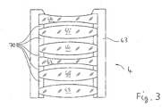
- the lens objective 4 comprises a lens barrel 63 and one or more lenses 64 to 69 held inside the lens barrel 63 and spaced from each other using ring shaped spacers 70.
- Each of the lenses 64 to 69 can have a spherical or an aspherical shape.
- the lens barrel 63 and the spacers 70 are preferably made of metal, in particular brass.
- the lens objective 4 may comprise lenses 64 to 69 made of different materials, for example glass and plastics.
- the lenses 65 and 69 may be made of plastics and the other lenses 64, 66, 68 may be made of glass.
- the lenses 64 to 69 may comprise positive lenses 65, 66, 68, 69 and negative lenses 64, 67.
- the dimensions and arrangement of the lenses 64 to 69 and the lens spacers 70 can be varied and specifically designed. For example, some lenses may be in touch condition without the use of lens spacers 70.
Landscapes
- Physics & Mathematics (AREA)
- General Physics & Mathematics (AREA)
- Engineering & Computer Science (AREA)
- Multimedia (AREA)
- Signal Processing (AREA)
- Lens Barrels (AREA)
Abstract
Description
- The invention relates to a camera module for a motor vehicle, comprising a camera housing, a lens objective comprises an opening allowing light to enter the camera module, and one or more electronic components including an image sensor adapted to sense light which is transmitted through the lens objective towards the image sensor.
- Typically, a metal camera housing and a metal lens objective are used for a vehicle-mounted camera system. The metal housing and lens objective are conductive. The conductive housing and lens objective protect the sensor from interfering with external electromagnetic waves.
- To reduce cost and weight, a plastic lens objective and a plastic housing is suggested. Such a camera housing is known for example from
DE 10 2015 205 436 A1 . However, a problem is that the plastic lens objective does not block electromagnetic waves to pass and reach the sensor. This means that the image sensor gets electrically exposed to the surrounding and other electrical devices nearby. - Additionally, the camera sensor emits electromagnetic waves and these can potentially disturb radio antennas and other electronic devices positioned in the camera module, adjacent the camera, and/or in windscreen approximately 10 cm to 20 cm apart from the sensor.
- This means that such a plastic housing and lens objective cannot get electromagnetic compatibility (EMC) approval.
- Positioning the sensor further into the housing would not solve the problem since there is no space available in the housing and the emitted radiation could widely spread.
- The problem underlying the present invention is to provide a camera module that is cost-effective and ensures electromagnetic compatibility approval.
- The invention solves this objective with the features of the independent claim.
- According to the invention, an electromagnetic waveguide filter is arranged around and/or within at least a portion of the lens objective, wherein the electromagnetic waveguide filter is adapted to electromagnetically shield the one or more electronic components from undesired electromagnetic radiation entering the camera housing and/or to shield the camera surrounding from undesired electromagnetic radiation leaving the camera housing.
- The invention has realized that an electromagnetic waveguide filter leads to an effective electromagnetic interference (EMI) protection. The camera module according to the invention provides electromagnetic immunity and blocks the external electric magnetic waves from reaching the one or more electronic components. The emission of electromagnetic radiation by the one or more electronic components is suppressed by the lens objective in combination with an electromagnetic waveguide filter. The electromagnetic waveguide filter ensures electromagnetic shielding and allows the use of a cost-effective non-shielding material for the barrel of the lens objective, for example plastics. The wave guide filter is used to shield the image sensor from interference with electronic devices in the surrounding of the camera module and/or to shield electronic components in the surrounding of the camera module from interference with the camera module.
- The image sensor is adapted to convert light containing image information incident on a sensitive surface of the image sensor into an electrical signal containing said image information. The image sensor can for example be sensitive in the visible spectrum of electromagnetic radiation, i.e. in a wave length range approximately between 380 nm and 780 nm. Other frequency bands, in particular optical radiation (wave length approximately 1 nm to 1 mm) of the electromagnetic spectrum could be sensed by the image sensor. Optical radiation comprises infra-red (IR, wave length approximately 780 nm to 1 mm) and/or ultra-violet (UV, wave length approximately 1 nm to 380 nm). Depending on the application, also other frequency bands could be sensed by the image sensor. However, micro waves, radio waves, and/or long-radio waves with a wave length larger 1 mm (and frequency smaller 30 GHz and in particular smaller than 10 GHz) are typically not desired to be sensed by the image sensor but can potentially disturb its function. Therefore, micro waves, radio waves, and/or long-radio waves with a frequency smaller than 10 GHz may be considered to be undesired electromagnetic waves.
- In other words, the electromagnetic waveguide filter is adapted to let only desired electromagnetic radiation, comprising the image information, entering the camera housing while shielding the surrounding from undesired radiation or noise radiation. Desired electromagnetic radiation is the radiation to be sensed by the image sensor, e.g., typically optical radiation, preferably visible light.
- Preferably, the electromagnetic waveguide filter is cylindrical and/or tube-shaped to match the typical shape of the lens objective and/or the lens barrel. In applications, the one or more lenses are round, rounded and/or elliptic rendering the lens objective having a typical tube-shape. The tube-shaped electromagnetic waveguide filter matches the form of typical lens objective and allows, due to its simple geometry, a detailed analysis of potentially attenuated electromagnetic modes of the electrical waves allowing a specific design according to shield electromagnetic radiation according to the specific application. In particular, the inner diameter of the waveguide filter preferably closely matches the outer diameter of the lens objective, for example within 3% or less.
- In a preferred embodiment, the electromagnetic waveguide filter is made of metal, in particular aluminum, to ensure a proper function and cost-effective production. Aluminum is particularly lightweight and cost-effective. However any electrically conductive material could be used, depending on the manufacturing process, and cost and weight constraints.
- In a preferred embodiment, the electromagnetic waveguide filter is made of an electrically non-conductive material and its surface is at least partly coated by an electrically conductive material. The electrically non-conductive material is preferably plastic. The conductive coating of the surface could be any conductive material, preferably metal, more preferably aluminum.
- Preferably, the electromagnetic waveguide filter is at least partly made of metal particles in an electrically non-conductive matrix. The electrically non-conductive matrix is preferably made of plastic and is adapted to support a plurality of metal particles in order to ensure electromagnetic shielding.
- Advantageously, the electromagnetic waveguide filter is integrated in the camera housing to provide a cost-effective one part housing - waveguide filter combination which can receive the lens objective. In particular, the electromagnetic waveguide filter and the camera housing are made of the same material as one piece.
- Preferably, the electromagnetic waveguide filter is attached to the lens objective at the outside thereof to allow the installation of the electromagnetic waveguide filter subsequent to the manufacturing of the lens objective. The attachment is preferably electrically conductive to ensure EMC approval.
- In a preferred embodiment, the electromagnetic waveguide filter is adapted to lower the surface power density that is emitted by the sensor and/or the electronic components to less than 1 µV/m in a distance of 15 cm from the sensor and/or from the electronic components, to ensure that other electrical devices outside and nearby the camera module are not influenced by the electromagnetic radiation leaving the camera module.
- Preferably, the electromagnetic waveguide filter has a length L and a diameter d and the ratio of length L and diameter d is larger than two in order to ensure that a proper high pass electromagnetic waveguide filter is formed. The high pass electromagnetic waveguide filter has a typical cutoff frequency below which no transmission of electric magnetic waves can take place.
- In a preferred embodiment, the electromagnetic waveguide filter is adapted to form a high pass filter with a cut-off frequency of at most 10 GHz, preferably at most 5 GHz, more preferably of 1.5 GHz in order to effectively shield electromagnetic radiation in an undesired frequency range within the motor vehicle. A typical undesired or noise frequency range within a motor vehicle is 27 MHz to 1.5 GHz.
- In the following the invention shall be illustrated on the basis of preferred embodiments with reference to the accompanying drawings, wherein:
- Fig. 1
- shows a schematic of a camera module according to the prior art;
- Fig. 2
- shows a schematic of a camera module according to the invention; and
- Fig. 3
- shows a schematic cross-sectional view of a lens objective.
- A
camera module 1 according to the state of the art is shown inFigure 1 . Thecamera module 1 according to prior art comprises a housing 2, a printedcircuit board 3, and alens objective 4 with aplastic lens barrel 63 and for example twolenses 10. Thelens barrel 63 and/or thelens objective 4 is adapted to hold the twolenses 10. Thelens barrel 63 and/or thelens objective 4 comprises an opening 6 allowing light to enter thecamera module 1. The printedcircuit board 3 comprises one or more electronic components including animage sensor 7 adapted to sense light which is transmitted through the one or moreoptical lenses 10 towards theimage sensor 7. The housing 2 comprises a through-hole 12 through which light enters thecamera module 1 via thelens objective 4. - The
camera module 1 is preferably a fixed focus camera module, where thelens objective 4 is afixed focus objective 4 having a fixed focus length which cannot be changed, and thelens objective 4 does not have movable parts for changing the focus length. - Electromagnetic radiation 9 can enter the
camera module 1 through thelens objective 4 and theplastic barrel 63 and/or thelens objective 4 and potentially disturb the at least onesensor 7 and/or other electrical components on the printedcircuit board 3. Also electromagnetic radiation 9 can leave thecamera module 1 through theplastic barrel 63 of thelens objective 4 and disturb electronic devices nearby thecamera module 1 in its surrounding 11. When a plastic housing 2 is used, electromagnetic radiation can also pass through the housing 2. -
Figure 2 shows thecamera module 1 according to the invention. In addition to the camera module offigure 1 , thecamera module 1 comprises aelectromagnetic waveguide filter 8 arranged around and/or within at least a portion of thelens barrel 63 and/or thelens objective 4. Theelectromagnetic waveguide filter 8 electromagnetically shields the one or more electronic components including theimage sensor 7 from undesired electromagnetic radiation entering the camera housing 2 and/or shields the camera surrounding 11 from undesired electromagnetic radiation leaving the camera housing 2. This makes the main housing 2 having a electromagnetic waveguide filter function in front of theimage sensor 7 so that an effective electromagnetic compatibility is ensured. - The
image sensor 7 detects incident electromagnetic radiation, preferably visible light and/or other optical radiation, and converts the incident light into electric current leading to an image signal that preferably can be processed by processing devices in the vehicle. Theimage sensor 7 is preferably a semi-conductor charge-coupled device (CCD), complementary metal-oxide-semiconductor (CMOS), or N-type metal-oxide-semi-conductor (NMOS, Live MOS). Preferably, theimage sensor 7 is a color sensor adapted to sense color images from the surrounding 11. - The
electromagnetic waveguide filter 8 is preferably integrated with the housing 2 and thereby an electrically conductive connection between theelectromagnetic waveguide filter 8 and the housing 2 is provided. The housing 2 and/or theelectromagnetic waveguide filter 8 are preferably made of aluminum but any electrically conductive material can be used. Also a non-metallic housing 2, e.g., a plastic housing 2, is possible and electrical shielding can be achieved by for example a metal coating, metal particles in non-conductive matrix, and/or other forms of suitable electromagnetic shields. Such a metal coating, metal particles in non-conductive matrix, and/or other forms of suitable electromagnetic shields can also be used for theelectromagnetic waveguide filter 8. - The
lens objective 4 can be constructed and manufactured to comprise theelectromagnetic waveguide filter 8 to ensure a cost-effective one-part construction. Thewave guide filter 8 can cover the outer face of thelens barrel 63 and/orlens objective 4 can be arranged within thelens barrel 63 and/or theobjective 4. In another embodiment which is not shown, the waveguide for the 8 can be attached to the housing 2 at a later stage, for example after thelens objective 4 is mounted to the housing 2. - In a preferred embodiment, the diameter, preferably the inner diameter, of the
electromagnetic waveguide filter 8 is adapted to match the diameter, preferably the outer diameter, of thelens objective 4 and/or thelens barrel 63. For example, matching said diameters means that the diameter of thewaveguide filter 8 is for example larger than the diameter of thelens objective 4 and/or thelens barrel 63 in order to allow mounting subsequent tomanufacturing waveguide filter 8 and thelens objective 4 and/or thelens barrel 63. In another example, matching said diameters means that the diameter of thewaveguide filter 8 equals for example the diameter of thelens objective 4 and/or thelens barrel 63 in order to allow integrated mounting of thewaveguide filter 8 and thelens objective 4 and/or thelens barrel 63 when thewaveguide filter 8 is arranged within thelens objective 4 and/or thelens barrel 63 . - In a preferred embodiment, the length of
waveguide filter 8 equals the length of thelens objective 4 and/or thelens barrel 63 to form areliable waveguide filter 8. In other embodiments, said length can be unequal to meet technical, constructive and/or visual criteria. - In a preferred embodiment, the
electromagnetic waveguide filter 8 has the shape of a cylindrical tube which will act as a waveguide. In this embodiment, theelectromagnetic waveguide filter 8 has a length L and a diameter d as shown inFigure 2 . The geometry and in particular the ratio of length and diameter L/d is crucial for the filter function of theelectromagnetic waveguide filter 8. Surprisingly a ratio of L/d > 2 forms theelectromagnetic waveguide filter 8 with high pass filter functionality and cutoff frequency of approximately 10 GHz which is well below the typical problem range in the vehicle of 27 MHz to 1.5 GHz. The signal amplitudes of the electric magnetic radiation is lowered from approximately 1 V/m inside the housing 2 to the order of magnitude of 1 µV/m in a distance of 15 cm measured from thesensor 7 in order to not disturb radio antennas nearby. - With respect to
Figure 3 , thelens objective 4 comprises alens barrel 63 and one ormore lenses 64 to 69 held inside thelens barrel 63 and spaced from each other using ring shapedspacers 70. Each of thelenses 64 to 69 can have a spherical or an aspherical shape. Thelens barrel 63 and thespacers 70 are preferably made of metal, in particular brass. - In particular, the
lens objective 4 may compriselenses 64 to 69 made of different materials, for example glass and plastics. In the embodiment ofFigure 3 , for example, thelenses other lenses 64, 66, 68 may be made of glass. Furthermore, thelenses 64 to 69 may comprisepositive lenses negative lenses 64, 67. Also, the dimensions and arrangement of thelenses 64 to 69 and thelens spacers 70 can be varied and specifically designed. For example, some lenses may be in touch condition without the use oflens spacers 70.
Claims (10)
- A camera module (1) for a motor vehicle, comprising- a camera housing (2),- a lens objective (4) comprises an opening (6) allowing light to enter the camera module (1), and- one or more electronic components including an image sensor (7) adapted to sense light which is transmitted through the lens objective (4) towards the image sensor (7),
characterized in that- an electromagnetic waveguide filter (8) is arranged around and/or within at least a portion of the lens objective (4), wherein the electromagnetic waveguide filter (8) is adapted to electromagnetically shield the one or more electronic components from undesired electromagnetic radiation entering the camera housing (2) and/or to shield the camera surrounding (11) from undesired electromagnetic radiation leaving the camera housing (2). - The camera module according to any one of the preceding claims, characterized in that- the electromagnetic waveguide filter (8) is tube-shaped.
- The camera module according to any one of the preceding claims, characterized in that- the electromagnetic waveguide filter (8) is made of a metal, in particular aluminum.
- The camera module according to any one of the preceding claims, characterized in that- the electromagnetic waveguide filter (8) is made of an electrically non-conductive material and its surface is at least partly coated by an electrically conductive material.
- The camera module according to any one of the preceding claims, characterized in that- the electromagnetic waveguide filter (8) is at least partly made of metal particles in an electrically non-conductive matrix.
- The camera module according to any one of the preceding claims, characterized in that- the electromagnetic waveguide filter (8) is integrated in the camera housing (2).
- The camera module according to any one of the preceding claims, characterized in that- the electromagnetic waveguide filter (8) is attached to the lens objective (4) at the outside of the lens objective (4).
- The camera module according to any one of the preceding claims, characterized in that- the electromagnetic waveguide filter (8) is adapted to lower the surface power density that is emitted by the one or more electronic components to less than 1 µV/m in a distance of 15 cm from the sensor (7) and/or from the electronic components.
- The camera module according to any one of the preceding claims, characterized in that- the electromagnetic waveguide filter (8) has a length L and a diameter d and- the ratio of length L and diameter d is larger than two.
- The camera module according to any one of the preceding claims, characterized in that- the electromagnetic waveguide filter (8) forms a high pass filter with a cut-off frequency of at most 10 GHz.
Priority Applications (1)
| Application Number | Priority Date | Filing Date | Title |
|---|---|---|---|
| EP17203609.7A EP3489750B1 (en) | 2017-11-24 | 2017-11-24 | A camera module for a motor vehicle |
Applications Claiming Priority (1)
| Application Number | Priority Date | Filing Date | Title |
|---|---|---|---|
| EP17203609.7A EP3489750B1 (en) | 2017-11-24 | 2017-11-24 | A camera module for a motor vehicle |
Publications (2)
| Publication Number | Publication Date |
|---|---|
| EP3489750A1 true EP3489750A1 (en) | 2019-05-29 |
| EP3489750B1 EP3489750B1 (en) | 2024-01-17 |
Family
ID=60484152
Family Applications (1)
| Application Number | Title | Priority Date | Filing Date |
|---|---|---|---|
| EP17203609.7A Active EP3489750B1 (en) | 2017-11-24 | 2017-11-24 | A camera module for a motor vehicle |
Country Status (1)
| Country | Link |
|---|---|
| EP (1) | EP3489750B1 (en) |
Cited By (1)
| Publication number | Priority date | Publication date | Assignee | Title |
|---|---|---|---|---|
| WO2025198269A1 (en) * | 2024-03-19 | 2025-09-25 | 엘지이노텍 주식회사 | Camera for vehicle |
Citations (7)
| Publication number | Priority date | Publication date | Assignee | Title |
|---|---|---|---|---|
| JPS5910078A (en) * | 1982-07-08 | 1984-01-19 | Konishiroku Photo Ind Co Ltd | Lens barrel for television camera |
| US20070279518A1 (en) * | 2004-01-13 | 2007-12-06 | Uwe Apel | Optical Module |
| WO2008061025A1 (en) * | 2006-11-09 | 2008-05-22 | Siimpel Corporation | Integrated lens barrel |
| US20100165103A1 (en) * | 2008-12-30 | 2010-07-01 | Paul Andreas Adrian | Camera Monitoring Systems And Methods For Electromagnetic Dryer Applicators |
| US20120243846A1 (en) * | 2010-12-20 | 2012-09-27 | David Blake Jackson | Integrated Security Video and Electromagnetic Pulse Detector |
| WO2012139024A1 (en) * | 2011-04-06 | 2012-10-11 | Emprimus, Inc. | Electromagnetically- shielded optical imaging system |
| DE102015205436A1 (en) | 2015-03-25 | 2016-09-29 | Robert Bosch Gmbh | Camera system for an environment detection system of a motor vehicle, method for mounting the camera system and method for producing the housing of the camera system |
Family Cites Families (1)
| Publication number | Priority date | Publication date | Assignee | Title |
|---|---|---|---|---|
| CN101498822B (en) * | 2008-02-03 | 2011-09-28 | 旭丽电子(广州)有限公司 | Lens module and manufacturing method thereof, and electronic device with the same |
-
2017
- 2017-11-24 EP EP17203609.7A patent/EP3489750B1/en active Active
Patent Citations (7)
| Publication number | Priority date | Publication date | Assignee | Title |
|---|---|---|---|---|
| JPS5910078A (en) * | 1982-07-08 | 1984-01-19 | Konishiroku Photo Ind Co Ltd | Lens barrel for television camera |
| US20070279518A1 (en) * | 2004-01-13 | 2007-12-06 | Uwe Apel | Optical Module |
| WO2008061025A1 (en) * | 2006-11-09 | 2008-05-22 | Siimpel Corporation | Integrated lens barrel |
| US20100165103A1 (en) * | 2008-12-30 | 2010-07-01 | Paul Andreas Adrian | Camera Monitoring Systems And Methods For Electromagnetic Dryer Applicators |
| US20120243846A1 (en) * | 2010-12-20 | 2012-09-27 | David Blake Jackson | Integrated Security Video and Electromagnetic Pulse Detector |
| WO2012139024A1 (en) * | 2011-04-06 | 2012-10-11 | Emprimus, Inc. | Electromagnetically- shielded optical imaging system |
| DE102015205436A1 (en) | 2015-03-25 | 2016-09-29 | Robert Bosch Gmbh | Camera system for an environment detection system of a motor vehicle, method for mounting the camera system and method for producing the housing of the camera system |
Cited By (1)
| Publication number | Priority date | Publication date | Assignee | Title |
|---|---|---|---|---|
| WO2025198269A1 (en) * | 2024-03-19 | 2025-09-25 | 엘지이노텍 주식회사 | Camera for vehicle |
Also Published As
| Publication number | Publication date |
|---|---|
| EP3489750B1 (en) | 2024-01-17 |
Similar Documents
| Publication | Publication Date | Title |
|---|---|---|
| KR102213027B1 (en) | Camera assembly with shielded imager circuit | |
| US10935873B2 (en) | Imaging device | |
| EP3227973B1 (en) | Camera for a motor vehicle and motor vehicle | |
| US8714840B2 (en) | Optical module and cage | |
| KR102354605B1 (en) | Camera Module | |
| CN202815392U (en) | Camera equipment | |
| US11881615B2 (en) | Antenna device for vehicle | |
| US20180337440A1 (en) | Antenna, wireless communication device, and electronic device | |
| US11199757B2 (en) | Imaging device | |
| US11381719B2 (en) | Imaging device | |
| JP4913093B2 (en) | Optical communication module and optical coupling portion covering member | |
| JP2019168509A (en) | Image capturing device | |
| US11246245B2 (en) | Camera | |
| JP2022008988A (en) | Connection structure and connection method between lens barrel pedestal and sensor substrate in camera unit | |
| EP3489750B1 (en) | A camera module for a motor vehicle | |
| US6857791B2 (en) | Optical device assembly with an anti-kink protector and transmitting/receiving module | |
| KR20220090580A (en) | Cameras and automobiles having housings for shielding electromagnetic radiation | |
| JP6681734B2 (en) | Electronic device housing | |
| US20170272633A1 (en) | Imager module for vehicle | |
| US10095086B2 (en) | Camera module | |
| KR101327622B1 (en) | Camera module | |
| US8933393B2 (en) | Electromagnetically-shielded optical system having a waveguide beyond cutoff extending through a shielding surface of an electromagnetically shielding enclosure | |
| JP2012215714A (en) | Lens unit, and imaging unit | |
| CN120928355A (en) | Sensor system | |
| KR101022971B1 (en) | Camera module |
Legal Events
| Date | Code | Title | Description |
|---|---|---|---|
| PUAI | Public reference made under article 153(3) epc to a published international application that has entered the european phase |
Free format text: ORIGINAL CODE: 0009012 |
|
| STAA | Information on the status of an ep patent application or granted ep patent |
Free format text: STATUS: THE APPLICATION HAS BEEN PUBLISHED |
|
| AK | Designated contracting states |
Kind code of ref document: A1 Designated state(s): AL AT BE BG CH CY CZ DE DK EE ES FI FR GB GR HR HU IE IS IT LI LT LU LV MC MK MT NL NO PL PT RO RS SE SI SK SM TR |
|
| AX | Request for extension of the european patent |
Extension state: BA ME |
|
| STAA | Information on the status of an ep patent application or granted ep patent |
Free format text: STATUS: REQUEST FOR EXAMINATION WAS MADE |
|
| 17P | Request for examination filed |
Effective date: 20191127 |
|
| RBV | Designated contracting states (corrected) |
Designated state(s): AL AT BE BG CH CY CZ DE DK EE ES FI FR GB GR HR HU IE IS IT LI LT LU LV MC MK MT NL NO PL PT RO RS SE SI SK SM TR |
|
| RIC1 | Information provided on ipc code assigned before grant |
Ipc: G03B 17/02 20210101AFI20210324BHEP Ipc: H04N 5/225 20060101ALI20210324BHEP Ipc: G03B 17/12 20210101ALI20210324BHEP |
|
| STAA | Information on the status of an ep patent application or granted ep patent |
Free format text: STATUS: EXAMINATION IS IN PROGRESS |
|
| 17Q | First examination report despatched |
Effective date: 20210430 |
|
| GRAP | Despatch of communication of intention to grant a patent |
Free format text: ORIGINAL CODE: EPIDOSNIGR1 |
|
| RIC1 | Information provided on ipc code assigned before grant |
Ipc: G03B 30/00 20210101ALI20230704BHEP Ipc: H04N 23/51 20230101ALI20230704BHEP Ipc: G03B 17/12 20060101ALI20230704BHEP Ipc: G03B 17/02 20060101AFI20230704BHEP |
|
| STAA | Information on the status of an ep patent application or granted ep patent |
Free format text: STATUS: GRANT OF PATENT IS INTENDED |
|
| INTG | Intention to grant announced |
Effective date: 20230810 |
|
| GRAS | Grant fee paid |
Free format text: ORIGINAL CODE: EPIDOSNIGR3 |
|
| GRAA | (expected) grant |
Free format text: ORIGINAL CODE: 0009210 |
|
| STAA | Information on the status of an ep patent application or granted ep patent |
Free format text: STATUS: THE PATENT HAS BEEN GRANTED |
|
| AK | Designated contracting states |
Kind code of ref document: B1 Designated state(s): AL AT BE BG CH CY CZ DE DK EE ES FI FR GB GR HR HU IE IS IT LI LT LU LV MC MK MT NL NO PL PT RO RS SE SI SK SM TR |
|
| REG | Reference to a national code |
Ref country code: GB Ref legal event code: FG4D |
|
| REG | Reference to a national code |
Ref country code: CH Ref legal event code: EP |
|
| REG | Reference to a national code |
Ref country code: DE Ref legal event code: R096 Ref document number: 602017078492 Country of ref document: DE |
|
| REG | Reference to a national code |
Ref country code: IE Ref legal event code: FG4D |
|
| REG | Reference to a national code |
Ref country code: DE Ref legal event code: R081 Ref document number: 602017078492 Country of ref document: DE Owner name: MAGNA ELECTRONICS SWEDEN AB, SE Free format text: FORMER OWNER: VEONEER SWEDEN AB, VARGARDA, SE |
|
| RAP4 | Party data changed (patent owner data changed or rights of a patent transferred) |
Owner name: MAGNA ELECTRONICS SWEDEN AB |
|
| REG | Reference to a national code |
Ref country code: LT Ref legal event code: MG9D |
|
| REG | Reference to a national code |
Ref country code: NL Ref legal event code: MP Effective date: 20240117 |
|
| RAP4 | Party data changed (patent owner data changed or rights of a patent transferred) |
Owner name: MAGNA ELECTRONICS SWEDEN AB |
|
| REG | Reference to a national code |
Ref country code: AT Ref legal event code: MK05 Ref document number: 1650928 Country of ref document: AT Kind code of ref document: T Effective date: 20240117 |
|
| PG25 | Lapsed in a contracting state [announced via postgrant information from national office to epo] |
Ref country code: NL Free format text: LAPSE BECAUSE OF FAILURE TO SUBMIT A TRANSLATION OF THE DESCRIPTION OR TO PAY THE FEE WITHIN THE PRESCRIBED TIME-LIMIT Effective date: 20240117 |
|
| PG25 | Lapsed in a contracting state [announced via postgrant information from national office to epo] |
Ref country code: NL Free format text: LAPSE BECAUSE OF FAILURE TO SUBMIT A TRANSLATION OF THE DESCRIPTION OR TO PAY THE FEE WITHIN THE PRESCRIBED TIME-LIMIT Effective date: 20240117 |
|
| PG25 | Lapsed in a contracting state [announced via postgrant information from national office to epo] |
Ref country code: IS Free format text: LAPSE BECAUSE OF FAILURE TO SUBMIT A TRANSLATION OF THE DESCRIPTION OR TO PAY THE FEE WITHIN THE PRESCRIBED TIME-LIMIT Effective date: 20240517 |
|
| PG25 | Lapsed in a contracting state [announced via postgrant information from national office to epo] |
Ref country code: LT Free format text: LAPSE BECAUSE OF FAILURE TO SUBMIT A TRANSLATION OF THE DESCRIPTION OR TO PAY THE FEE WITHIN THE PRESCRIBED TIME-LIMIT Effective date: 20240117 |
|
| PG25 | Lapsed in a contracting state [announced via postgrant information from national office to epo] |
Ref country code: GR Free format text: LAPSE BECAUSE OF FAILURE TO SUBMIT A TRANSLATION OF THE DESCRIPTION OR TO PAY THE FEE WITHIN THE PRESCRIBED TIME-LIMIT Effective date: 20240418 |
|
| PG25 | Lapsed in a contracting state [announced via postgrant information from national office to epo] |
Ref country code: RS Free format text: LAPSE BECAUSE OF FAILURE TO SUBMIT A TRANSLATION OF THE DESCRIPTION OR TO PAY THE FEE WITHIN THE PRESCRIBED TIME-LIMIT Effective date: 20240417 Ref country code: HR Free format text: LAPSE BECAUSE OF FAILURE TO SUBMIT A TRANSLATION OF THE DESCRIPTION OR TO PAY THE FEE WITHIN THE PRESCRIBED TIME-LIMIT Effective date: 20240117 |
|
| PG25 | Lapsed in a contracting state [announced via postgrant information from national office to epo] |
Ref country code: ES Free format text: LAPSE BECAUSE OF FAILURE TO SUBMIT A TRANSLATION OF THE DESCRIPTION OR TO PAY THE FEE WITHIN THE PRESCRIBED TIME-LIMIT Effective date: 20240117 |
|
| PG25 | Lapsed in a contracting state [announced via postgrant information from national office to epo] |
Ref country code: AT Free format text: LAPSE BECAUSE OF FAILURE TO SUBMIT A TRANSLATION OF THE DESCRIPTION OR TO PAY THE FEE WITHIN THE PRESCRIBED TIME-LIMIT Effective date: 20240117 |
|
| PG25 | Lapsed in a contracting state [announced via postgrant information from national office to epo] |
Ref country code: RS Free format text: LAPSE BECAUSE OF FAILURE TO SUBMIT A TRANSLATION OF THE DESCRIPTION OR TO PAY THE FEE WITHIN THE PRESCRIBED TIME-LIMIT Effective date: 20240417 Ref country code: NO Free format text: LAPSE BECAUSE OF FAILURE TO SUBMIT A TRANSLATION OF THE DESCRIPTION OR TO PAY THE FEE WITHIN THE PRESCRIBED TIME-LIMIT Effective date: 20240417 Ref country code: LT Free format text: LAPSE BECAUSE OF FAILURE TO SUBMIT A TRANSLATION OF THE DESCRIPTION OR TO PAY THE FEE WITHIN THE PRESCRIBED TIME-LIMIT Effective date: 20240117 Ref country code: IS Free format text: LAPSE BECAUSE OF FAILURE TO SUBMIT A TRANSLATION OF THE DESCRIPTION OR TO PAY THE FEE WITHIN THE PRESCRIBED TIME-LIMIT Effective date: 20240517 Ref country code: HR Free format text: LAPSE BECAUSE OF FAILURE TO SUBMIT A TRANSLATION OF THE DESCRIPTION OR TO PAY THE FEE WITHIN THE PRESCRIBED TIME-LIMIT Effective date: 20240117 Ref country code: GR Free format text: LAPSE BECAUSE OF FAILURE TO SUBMIT A TRANSLATION OF THE DESCRIPTION OR TO PAY THE FEE WITHIN THE PRESCRIBED TIME-LIMIT Effective date: 20240418 Ref country code: FI Free format text: LAPSE BECAUSE OF FAILURE TO SUBMIT A TRANSLATION OF THE DESCRIPTION OR TO PAY THE FEE WITHIN THE PRESCRIBED TIME-LIMIT Effective date: 20240117 Ref country code: ES Free format text: LAPSE BECAUSE OF FAILURE TO SUBMIT A TRANSLATION OF THE DESCRIPTION OR TO PAY THE FEE WITHIN THE PRESCRIBED TIME-LIMIT Effective date: 20240117 Ref country code: BG Free format text: LAPSE BECAUSE OF FAILURE TO SUBMIT A TRANSLATION OF THE DESCRIPTION OR TO PAY THE FEE WITHIN THE PRESCRIBED TIME-LIMIT Effective date: 20240117 Ref country code: AT Free format text: LAPSE BECAUSE OF FAILURE TO SUBMIT A TRANSLATION OF THE DESCRIPTION OR TO PAY THE FEE WITHIN THE PRESCRIBED TIME-LIMIT Effective date: 20240117 |
|
| PG25 | Lapsed in a contracting state [announced via postgrant information from national office to epo] |
Ref country code: PL Free format text: LAPSE BECAUSE OF FAILURE TO SUBMIT A TRANSLATION OF THE DESCRIPTION OR TO PAY THE FEE WITHIN THE PRESCRIBED TIME-LIMIT Effective date: 20240117 Ref country code: PT Free format text: LAPSE BECAUSE OF FAILURE TO SUBMIT A TRANSLATION OF THE DESCRIPTION OR TO PAY THE FEE WITHIN THE PRESCRIBED TIME-LIMIT Effective date: 20240517 |
|
| PG25 | Lapsed in a contracting state [announced via postgrant information from national office to epo] |
Ref country code: SE Free format text: LAPSE BECAUSE OF FAILURE TO SUBMIT A TRANSLATION OF THE DESCRIPTION OR TO PAY THE FEE WITHIN THE PRESCRIBED TIME-LIMIT Effective date: 20240117 Ref country code: PT Free format text: LAPSE BECAUSE OF FAILURE TO SUBMIT A TRANSLATION OF THE DESCRIPTION OR TO PAY THE FEE WITHIN THE PRESCRIBED TIME-LIMIT Effective date: 20240517 Ref country code: PL Free format text: LAPSE BECAUSE OF FAILURE TO SUBMIT A TRANSLATION OF THE DESCRIPTION OR TO PAY THE FEE WITHIN THE PRESCRIBED TIME-LIMIT Effective date: 20240117 Ref country code: LV Free format text: LAPSE BECAUSE OF FAILURE TO SUBMIT A TRANSLATION OF THE DESCRIPTION OR TO PAY THE FEE WITHIN THE PRESCRIBED TIME-LIMIT Effective date: 20240117 |
|
| PG25 | Lapsed in a contracting state [announced via postgrant information from national office to epo] |
Ref country code: DK Free format text: LAPSE BECAUSE OF FAILURE TO SUBMIT A TRANSLATION OF THE DESCRIPTION OR TO PAY THE FEE WITHIN THE PRESCRIBED TIME-LIMIT Effective date: 20240117 |
|
| PG25 | Lapsed in a contracting state [announced via postgrant information from national office to epo] |
Ref country code: SM Free format text: LAPSE BECAUSE OF FAILURE TO SUBMIT A TRANSLATION OF THE DESCRIPTION OR TO PAY THE FEE WITHIN THE PRESCRIBED TIME-LIMIT Effective date: 20240117 |
|
| REG | Reference to a national code |
Ref country code: DE Ref legal event code: R097 Ref document number: 602017078492 Country of ref document: DE |
|
| PG25 | Lapsed in a contracting state [announced via postgrant information from national office to epo] |
Ref country code: EE Free format text: LAPSE BECAUSE OF FAILURE TO SUBMIT A TRANSLATION OF THE DESCRIPTION OR TO PAY THE FEE WITHIN THE PRESCRIBED TIME-LIMIT Effective date: 20240117 Ref country code: CZ Free format text: LAPSE BECAUSE OF FAILURE TO SUBMIT A TRANSLATION OF THE DESCRIPTION OR TO PAY THE FEE WITHIN THE PRESCRIBED TIME-LIMIT Effective date: 20240117 |
|
| PG25 | Lapsed in a contracting state [announced via postgrant information from national office to epo] |
Ref country code: SK Free format text: LAPSE BECAUSE OF FAILURE TO SUBMIT A TRANSLATION OF THE DESCRIPTION OR TO PAY THE FEE WITHIN THE PRESCRIBED TIME-LIMIT Effective date: 20240117 |
|
| PG25 | Lapsed in a contracting state [announced via postgrant information from national office to epo] |
Ref country code: SM Free format text: LAPSE BECAUSE OF FAILURE TO SUBMIT A TRANSLATION OF THE DESCRIPTION OR TO PAY THE FEE WITHIN THE PRESCRIBED TIME-LIMIT Effective date: 20240117 Ref country code: SK Free format text: LAPSE BECAUSE OF FAILURE TO SUBMIT A TRANSLATION OF THE DESCRIPTION OR TO PAY THE FEE WITHIN THE PRESCRIBED TIME-LIMIT Effective date: 20240117 Ref country code: RO Free format text: LAPSE BECAUSE OF FAILURE TO SUBMIT A TRANSLATION OF THE DESCRIPTION OR TO PAY THE FEE WITHIN THE PRESCRIBED TIME-LIMIT Effective date: 20240117 Ref country code: EE Free format text: LAPSE BECAUSE OF FAILURE TO SUBMIT A TRANSLATION OF THE DESCRIPTION OR TO PAY THE FEE WITHIN THE PRESCRIBED TIME-LIMIT Effective date: 20240117 Ref country code: DK Free format text: LAPSE BECAUSE OF FAILURE TO SUBMIT A TRANSLATION OF THE DESCRIPTION OR TO PAY THE FEE WITHIN THE PRESCRIBED TIME-LIMIT Effective date: 20240117 Ref country code: CZ Free format text: LAPSE BECAUSE OF FAILURE TO SUBMIT A TRANSLATION OF THE DESCRIPTION OR TO PAY THE FEE WITHIN THE PRESCRIBED TIME-LIMIT Effective date: 20240117 |
|
| PLBE | No opposition filed within time limit |
Free format text: ORIGINAL CODE: 0009261 |
|
| STAA | Information on the status of an ep patent application or granted ep patent |
Free format text: STATUS: NO OPPOSITION FILED WITHIN TIME LIMIT |
|
| PG25 | Lapsed in a contracting state [announced via postgrant information from national office to epo] |
Ref country code: IT Free format text: LAPSE BECAUSE OF FAILURE TO SUBMIT A TRANSLATION OF THE DESCRIPTION OR TO PAY THE FEE WITHIN THE PRESCRIBED TIME-LIMIT Effective date: 20240117 |
|
| 26N | No opposition filed |
Effective date: 20241018 |
|
| PG25 | Lapsed in a contracting state [announced via postgrant information from national office to epo] |
Ref country code: IT Free format text: LAPSE BECAUSE OF FAILURE TO SUBMIT A TRANSLATION OF THE DESCRIPTION OR TO PAY THE FEE WITHIN THE PRESCRIBED TIME-LIMIT Effective date: 20240117 |
|
| PG25 | Lapsed in a contracting state [announced via postgrant information from national office to epo] |
Ref country code: SI Free format text: LAPSE BECAUSE OF FAILURE TO SUBMIT A TRANSLATION OF THE DESCRIPTION OR TO PAY THE FEE WITHIN THE PRESCRIBED TIME-LIMIT Effective date: 20240117 |
|
| REG | Reference to a national code |
Ref country code: CH Ref legal event code: PL |
|
| PG25 | Lapsed in a contracting state [announced via postgrant information from national office to epo] |
Ref country code: MC Free format text: LAPSE BECAUSE OF FAILURE TO SUBMIT A TRANSLATION OF THE DESCRIPTION OR TO PAY THE FEE WITHIN THE PRESCRIBED TIME-LIMIT Effective date: 20240117 |
|
| PG25 | Lapsed in a contracting state [announced via postgrant information from national office to epo] |
Ref country code: LU Free format text: LAPSE BECAUSE OF NON-PAYMENT OF DUE FEES Effective date: 20241124 |
|
| REG | Reference to a national code |
Ref country code: CH Ref legal event code: PL |
|
| GBPC | Gb: european patent ceased through non-payment of renewal fee |
Effective date: 20241124 |
|
| PG25 | Lapsed in a contracting state [announced via postgrant information from national office to epo] |
Ref country code: CH Free format text: LAPSE BECAUSE OF NON-PAYMENT OF DUE FEES Effective date: 20241130 |
|
| REG | Reference to a national code |
Ref country code: BE Ref legal event code: MM Effective date: 20241130 |
|
| PG25 | Lapsed in a contracting state [announced via postgrant information from national office to epo] |
Ref country code: GB Free format text: LAPSE BECAUSE OF NON-PAYMENT OF DUE FEES Effective date: 20241124 Ref country code: BE Free format text: LAPSE BECAUSE OF NON-PAYMENT OF DUE FEES Effective date: 20241130 |
|
| PG25 | Lapsed in a contracting state [announced via postgrant information from national office to epo] |
Ref country code: IE Free format text: LAPSE BECAUSE OF NON-PAYMENT OF DUE FEES Effective date: 20241124 |
|
| PGFP | Annual fee paid to national office [announced via postgrant information from national office to epo] |
Ref country code: DE Payment date: 20251118 Year of fee payment: 9 |
|
| PGFP | Annual fee paid to national office [announced via postgrant information from national office to epo] |
Ref country code: FR Payment date: 20251125 Year of fee payment: 9 |
|
| PG25 | Lapsed in a contracting state [announced via postgrant information from national office to epo] |
Ref country code: HU Free format text: LAPSE BECAUSE OF FAILURE TO SUBMIT A TRANSLATION OF THE DESCRIPTION OR TO PAY THE FEE WITHIN THE PRESCRIBED TIME-LIMIT; INVALID AB INITIO Effective date: 20171124 |
|
| PG25 | Lapsed in a contracting state [announced via postgrant information from national office to epo] |
Ref country code: CY Free format text: LAPSE BECAUSE OF FAILURE TO SUBMIT A TRANSLATION OF THE DESCRIPTION OR TO PAY THE FEE WITHIN THE PRESCRIBED TIME-LIMIT; INVALID AB INITIO Effective date: 20171124 |
|
| PG25 | Lapsed in a contracting state [announced via postgrant information from national office to epo] |
Ref country code: TR Free format text: LAPSE BECAUSE OF FAILURE TO SUBMIT A TRANSLATION OF THE DESCRIPTION OR TO PAY THE FEE WITHIN THE PRESCRIBED TIME-LIMIT Effective date: 20240117 |