EP3489640A1 - Vibrometer assembly, rotating machine, and vibrometer attachment method and removal method - Google Patents
Vibrometer assembly, rotating machine, and vibrometer attachment method and removal method Download PDFInfo
- Publication number
- EP3489640A1 EP3489640A1 EP16923353.3A EP16923353A EP3489640A1 EP 3489640 A1 EP3489640 A1 EP 3489640A1 EP 16923353 A EP16923353 A EP 16923353A EP 3489640 A1 EP3489640 A1 EP 3489640A1
- Authority
- EP
- European Patent Office
- Prior art keywords
- vibrometer
- case
- probe
- attachment
- guide cylinder
- Prior art date
- Legal status (The legal status is an assumption and is not a legal conclusion. Google has not performed a legal analysis and makes no representation as to the accuracy of the status listed.)
- Granted
Links
Images




Classifications
-
- G—PHYSICS
- G01—MEASURING; TESTING
- G01H—MEASUREMENT OF MECHANICAL VIBRATIONS OR ULTRASONIC, SONIC OR INFRASONIC WAVES
- G01H1/00—Measuring characteristics of vibrations in solids by using direct conduction to the detector
- G01H1/003—Measuring characteristics of vibrations in solids by using direct conduction to the detector of rotating machines
-
- G—PHYSICS
- G01—MEASURING; TESTING
- G01M—TESTING STATIC OR DYNAMIC BALANCE OF MACHINES OR STRUCTURES; TESTING OF STRUCTURES OR APPARATUS, NOT OTHERWISE PROVIDED FOR
- G01M13/00—Testing of machine parts
- G01M13/04—Bearings
- G01M13/045—Acoustic or vibration analysis
-
- G—PHYSICS
- G01—MEASURING; TESTING
- G01H—MEASUREMENT OF MECHANICAL VIBRATIONS OR ULTRASONIC, SONIC OR INFRASONIC WAVES
- G01H1/00—Measuring characteristics of vibrations in solids by using direct conduction to the detector
-
- G—PHYSICS
- G01—MEASURING; TESTING
- G01M—TESTING STATIC OR DYNAMIC BALANCE OF MACHINES OR STRUCTURES; TESTING OF STRUCTURES OR APPARATUS, NOT OTHERWISE PROVIDED FOR
- G01M13/00—Testing of machine parts
- G01M13/02—Gearings; Transmission mechanisms
- G01M13/028—Acoustic or vibration analysis
Definitions
- the present invention relates to a vibrometer assembly, a rotating machine including the vibrometer assembly, a method for attaching a vibrometer to the rotating machine, and a method for removing the vibrometer from the rotating machine.
- a rotating machine such as a compressor includes a vibrometer (Patent Literature 1).
- the vibrometer in Patent Literature 1 includes a probe which is used for measuring a distance from a surface of a rotating shaft by an eddy current, a wire (conductor) drawn from the probe, and an elongated probe holder, and is generally formed into a rod shape.
- the vibrometer is passed through a cylinder penetrating a case of a compressor or the like in a thickness direction, and secured to an end of the cylinder outside the case.
- Patent Literature 1 U.S. Patent No. 4066949
- the vibrometer in Patent Literature 1 is secured to the case of the compressor or the like through the cylinder, but a distal end protruding into the case is not secured. Then, in trying to secure the distal end of the vibrometer near the rotating shaft, the distal end of the vibrometer is distant from the case, and even if the vibrometer is passed straight through the cylinder penetrating the case in the thickness direction, the distal end of the vibrometer cannot be smoothly inserted into a securing portion due to errors in machining or assembling, slight swing of the vibrometer in the cylinder, or the like.
- the present invention with respect to a vibrometer included in a rotating machine, has an object to provide a vibrometer assembly that facilitates a vibrometer attachment operation, a rotating machine including the vibrometer assembly, a method for attaching the vibrometer, and a method for removing the vibrometer.
- a vibrometer assembly including a vibrometer configured to measure vibration of a rotating shaft, including: a probe of the vibrometer that is to be secured to a bearing device that supports the rotating shaft; a guide cylinder that is to be provided to a case so as to penetrate the case and protrude into the case, the case being located outside the bearing device; an attachment that is to be connected to the probe and inserted into the guide cylinder, and at least partially has a movable portion to allow the probe to be axially aligned with an inside securing portion in the bearing device; and an outside securing portion that secures the attachment to the guide cylinder or the case outside the case.
- the inside securing portion includes a female thread that is provided in a housing of the bearing device to secure the probe, and the outside securing portion includes a fixture that secures an end of the attachment to the guide cylinder outside the case.
- the attachment preferably has a plurality of joints arranged in a length direction of the guide cylinder.
- the attachment has a plurality of parts, the parts adjacent to each other in the length direction forming the plurality of joins by being coupled by pins at least four points, the pins for two of the four points being directed perpendicularly to the pins for the other two points.
- a seal is preferably provided to seal a radial gap between the guide cylinder and the attachment.
- packing is provided to the probe so as to be brought into close contact with an outer periphery of a conductor drawn through an inside of the attachment to an outside of the case.
- the vibrometer assembly of the above aspect of the present invention preferably includes a cap that is to be mounted to the guide cylinder or the case so as to cover the outside securing portion.
- Another aspect of the present invention provides a rotating machine including: the vibrometer assembly described above; a rotating shaft; a bearing; and a case.
- the guide cylinder penetrating the case provides a path for securing or releasing the probe to or from the bearing device.
- the vibrometer can be attached or removed through the guide cylinder from outside the case.
- the vibrometer is secured at two points: at the bearing device and at or near the case. It is difficult to secure the attachment and the probe to the inside securing portion in the bearing device due to errors or the like during hole machining or assembly even if the attachment and the probe are inserted straight through the guide cylinder.
- the guide cylinder it is enabled to guide the probe to a position of the inside securing portion, and further by the attachment it is enabled to axially align the probe with the inside securing portion, thereby allowing the probe to be easily secured to the inside securing portion.
- a compressor is shown as an example of a rotating machine including a vibrometer 20.
- a compressor 1 in FIG. 1 includes a rotating shaft 11 to which a compression mechanism (not shown) such as an impeller (a bladed wheel) is coupled, a case 12 (casing) that houses the compression mechanism, and a bearing device 10 that supports the rotating shaft 11.
- a compression mechanism such as an impeller (a bladed wheel)
- a case 12 casing
- a bearing device 10 that supports the rotating shaft 11.
- the compressor 1 constitutes part of a facility such as a plant.
- the compressor 1 compresses gas introduced from outside into the case 12 using the compression mechanism and discharges the gas out of the case 12.
- An end 11A of the horizontally extending rotating shaft 11 protrudes from one end side of the case 12, and is supported by the bearing device 10.
- An opposite end (not shown in FIG. 1 ) of the rotating shaft 11 also protrudes from the other end side of the case 12, and is supported by a journal bearing (not shown).
- the bearing device 10 includes a journal bearing 14 that rotatably supports the rotating shaft 11, a bearing housing 15 that holds the journal bearing 14, thrust bearings 16 that axially support the rotating shaft 11, and a housing 17 that holds the thrust bearings 16.
- the journal bearing 14 surrounds an outer periphery of the rotating shaft 11, and the thrust bearings 16 are arranged on opposite sides of a flange 11C protruding radially outward from the rotating shaft 11.
- the bearings 14, 16 are lubricated with a lubricant.
- the bearing device 10 and a portion of the rotating shaft 11 protruding from the case 12 are covered with a cover case 121 provided to the case 12.
- a cover case 121 provided to the case 12.
- the case 12 is not shown cutaway, but only the cover case 121 is shown cutaway.
- an ambience of the inside of the cover case 121 is the air.
- the compressor 1 To monitor vibration of the rotating shaft 11 and make the compressor 1 stably operate, the compressor 1 includes a vibrometer 20 that measures the vibration of the rotating shaft 11.
- the vibrometer 20 measures vibration displacement of the rotating shaft 11 and a position of the rotating shaft 11 based on the vibration displacement, by using a distance between a distal end 201 close to an outer peripheral surface of the rotating shaft 11 and the outer peripheral surface of the rotating shaft 11.
- the distal end 201 of the vibrometer 20 is not in contact with the outer peripheral surface of the rotating shaft 11.
- the vibrometer 20 is preferably also provided in a housing of the journal bearing (not shown) that supports the end opposite to the end 11A of the rotating shaft 11.
- the vibrometer 20 may be similarly provided in the housing 17 of the thrust bearings 16.
- the vibrometer 20 and a member assembled to the vibrometer 20 are generally in the form of an elongated rod, and arranged toward the axial center of the rotating shaft 11 along a radial direction D1 of the bearing housing 15. To measure vibration displacement in any radial directions, two vibrometers 20 are actually provided and arranged perpendicularly to each other.
- This embodiment has a main feature in a configuration of the vibrometer assembly 2 including the vibrometer 20.
- the vibrometer assembly 2 includes, besides the vibrometer 20, part of the cover case 121, part of the bearing housing 15, an attachment 30 and a guide cylinder 40 both for supporting an operation for attaching the vibrometer 20 to the compressor 1, and an outside securing nut 45 (fixture) that secures the attachment 30 to the cover case 121.
- the vibrometer 20 includes a probe 21 that measures a distance up to the outer peripheral surface of the rotating shaft 11, and a conductor 22 (shown by dot-and-dash line) drawn from the probe 21.
- the vibrometer 20 may be a known distance measuring sensor that can detect a distance such as an eddy-current type or capacitance type sensor. An electric signal indicating the distance up to the outer peripheral surface 11B of the rotating shaft 11, the distance being detected by the probe 21 made of metal and energized through the conductor 22, is transmitted to a control circuit unit (not shown) through a different conductor 22.
- the probe 21 in this embodiment is linearly formed, and on at least a distal end side of an outer periphery of the probe 21 a thread 21A is provided.
- the probe 21 is shorter than a distance between the bearing housing 15 and the cover case 121.
- the bearing housing 15 has a round hole 151 into which the probe 21 is inserted, and a female thread 152 continuous with the round hole 151.
- the thread 21A on the probe 21 is screwed into the female thread 152 to secure the probe 21 to the bearing housing 15.
- the probe 21 protrudes from the round hole 151 radially outward of the bearing housing 15 while being secured to the bearing housing 15.
- the round hole 151 and the female thread 152 are formed toward the axial center of the rotating shaft 11 along the radial direction of the bearing housing 15.
- the axial center of the round hole 151 substantially matches the axial center of the female thread 152.
- the round hole 151 and the female thread 152 are collectively referred to as an inside insertion securing hole 150 (an inside securing portion).
- the distal end of the probe 21 (the distal end 201 of the vibrometer 20) closely faces the outer peripheral surface 11B of the rotating shaft 11.
- the bearing housing 15 has a recess 153 recessed from an outer periphery 15A, and an opening 151A of the round hole 151 is located at a bottom of the recess 153. Inside the recess 153, the probe 21 and the attachment 30 are connected with each other.
- the attachment 30 and the probe 21 may be connected outside the outer periphery 15A of the bearing housing 15. In that case, there is no need for the recess 153, and the round hole 151 may open in the outer periphery 15A.
- the vibrometer 20 and the member assembled to the vibrometer 20 are generally arranged inside the cover case 121.
- the probe 21 can be screwed to the bearing housing 15 by the thread 21A on the probe 21 and a nut attached to a portion of the probe 21 protruding from the bearing housing 15, and the conductor 22 drawn from the probe 21 can be connected to a terminal (not shown) prepared in the compressor 1.
- the complete set of vibrometer 20 is arranged inside the cover case 121, it is necessary to open the cover case 121 to access the vibrometer 20 for attaching or removing the vibrometer 20 in case of a fault or the like of the vibrometer 20. If at least part of the cover case 121 is removed, part of the rotating shaft 11 is exposed. Thus, the compressor 1 in operation needs to be suspended in view of safety.
- the vibrometer 20 is passed through a through hole 122 penetrating the cover case 121 in a thickness direction, and wherein from the outside of the cover case 121, the distal end 201 of the vibrometer 20 is secured to or removed from the bearing housing 15.
- the inside insertion securing hole 150 (the round hole 151 and the female thread 152) and the through hole 122 are machined so that the axial center of the inside insertion securing hole 150 matches the axial center of the through hole 122. Even if the guide cylinder 40 is used to support the operation for inserting the vibrometer 20 into the through hole 122 and the inside insertion securing hole 150, that alone does not allow the vibrometer 20 to be smoothly inserted into the inside insertion securing hole 150 due to errors in machining, errors in assembly of the bearing housing 15, the cover case 121, and the guide cylinder 40, swing of the probe 21 inside the guide cylinder 40, or the like.
- the probe 21 can be inserted into an innermost part of the inside insertion securing hole 150 to secure the thread 21A on the probe 21 to the bearing housing 15 only when the probe 21 is inserted straight into the inside insertion securing hole 150 with the axial center of the inside insertion securing hole 150 being aligned with the axial center of the probe 21.
- an attachment 30 ( FIGS. 2 and 3 ) connected to the probe 21 is used in addition to the guide cylinder 40.
- the attachment 30 extends radially outward of the bearing housing 15 so as to be continuous with the probe 21, and penetrates the through hole 122 to reach the outside of the cover case 121.
- the attachment 30 is passed through the inside of the guide cylinder 40 penetrating the cover case 121, and has a plurality of (four here) joints 31 to 34 arranged in a length direction of the guide cylinder 40.
- the attachment 30 at least partially has the joints 31 to 34 as movable portions that can move the axial center of the probe 21 to axially align the probe 21 with the inside insertion securing hole 150.
- the attachment 30 includes five cylindrical parts 301 to 305 that form the joints 31 to 34.
- the parts adjacent to each other are coupled by pins to form joints bendable around the pins (P1, P2).
- the part 301 connected to the probe 21 and the next part 302 form the joint 31.
- the parts 301 to 305 are made of any metal material as necessary.
- An orientation of the pins P1 in the two joints 31,33 among the joints 31 to 34 is perpendicular to an orientation of the pins P2 in the other two joints 32, 34.
- the parts 301 to 305 each have a pair of pawls 30N, 30N on opposite sides in a width direction, and the pawls 30N, 30N are connected by a pair of pins pivotally supported.
- the conductor 22 of the vibrometer 20 is passed through a cylindrical space Sp formed inside each of the parts 301 to 305.
- the three parts 302 to 304 are formed to have the same shape as shown in FIG. 3A .
- the parts 302 to 304 are coupled so that the pins P1, P2 are alternately oriented.
- the parts 302 to 304 do not always need to be alternately coupled.
- the part 301 ( FIG. 3B ) coupled to the part 302 is connected to an end 21B ( FIG. 2 ) of the probe 21 protruding from the round hole 151 radially outward of the bearing housing 15.
- the part 301 is arranged in the recess 153 in the bearing housing 15, but not limited to this, and may be arranged outside the outer periphery 15A of the bearing housing 15.
- the end 21B of the probe 21 is screwed into a female thread 301A ( FIG. 3B ) formed inside the part 301, and secured to the part 301 by a double nut 301W ( FIG. 2 ) for locking.
- the double nut 301W is rotated to adjust an insertion depth of the probe 21 into the female thread 301A, thereby increasing or decreasing a total length from the distal end 201 of the probe 21 to an outside end 30B of the part 305.
- the part 305 ( FIG. 3C ) coupled to the part 304 is secured to the guide cylinder 40 by an outside securing nut 45 ( FIG. 2 ) provided on an outer periphery of a protruding portion of outward the guide cylinder 40 and the cover case 121. Washers 451, 452 are held between the outside securing nut 45 and an upper end of the guide cylinder 40.
- the length of the attachment 30 and the probe 21 (total length) is adjusted to a defined length by the double nut 301W so that the probe 21 is close to the rotating shaft 11 so as to be able to accurately detect vibration of the rotating shaft 11 and the attachment 30 can be secured to the guide cylinder 40 by the outside securing nut.
- the vibrometer assembly 2 of this embodiment includes a seal 51, packing 52, a packing retainer 53, and a cap 54.
- the seal 51 is an O ring, and the seal 51 is arranged in a groove 305A ( FIG. 3C ) annularly formed along an outer periphery of the part 305, and intermediated in a compressed manner between the outer periphery of the part 305 and the inner wall of the guide cylinder 40 to seal a radial gap between the part 305 and the guide cylinder 40.
- the packing 52 is mounted to the outside end 30B so that the conductor 22 exposed from the outside end 30B of the part 305 is passed through the packing 52.
- the packing 52 is pressed by the packing retainer 53 screwed onto a male thread 305B ( FIG. 3C ) on the part 305, and then is brought into close contact with an outer periphery of the conductor 22.
- the cap 54 is mounted to the guide cylinder 40 so as to cover the outside securing nut 45 and the packing retainer 53.
- the conductor 22 is drawn, through the through holes in the packing retainer 53 and the cap 54, to outside the cap 54.
- a sealing tape (not shown) is preferably provided between a cap attaching portion 41 on the guide cylinder 40 and a female thread in the cap 54.
- the sealing tape is compressed between the cap attaching portion 41 and the female thread both having a tapered shape, to eliminate a gap between the cap 54 and the guide cylinder 40.
- Covering with the cap 54 can protect the attachment 30, the outside securing nut 45, the packing 52, and the like from external environment, external forces, and the like.
- the cap 54 may be mounted to a cap attaching portion formed on the cover case 121.
- the packing 52 and either one of the seal 51 or the cap 54 may be selected.
- the guide cylinder 40 ( FIG. 2 ) is formed of a metal material into a cylindrical shape, and radially protrudes from the outside to the inside of the cover case 121 by penetrating the inside of the through hole 122.
- the attachment 30 is inserted into a cylindrical space formed inside the guide cylinder 40 having a certain inner diameter.
- a predetermined clearance is set between the inner wall of the guide cylinder 40 and the parts 301 to 305 of the attachment 30 so that the attachment 30 and the probe 21 can be smoothly inserted into the guide cylinder 40.
- the guide cylinder 40 linearly corrects postures of the parts 301 to 305 connected to the probe 21, and guides the probe 21 and the attachment 30 up to the position of the inside insertion securing hole 150 in the bearing housing 15.
- the part 305 of the attachment 30 is, by the outside securing nut 45, secured to an end surface 40A at the upper end of the guide cylinder 40 protruding outward of the cover case 121.
- the cap attaching portion 41 to which the cap 54 is mounted is formed at an upper portion than a flange 42 formed on an outer periphery of the upper end of the guide cylinder 40.
- the cap attaching portion 41 and a case attaching portion 43 described below are formed to be thicker than a portion below the case attaching portion 43.
- the guide cylinder 40 is secured to the cover case 121 by the case attaching portion 43 formed on the outer periphery of the lower portion than the flange 42 being screwed into a female thread 122A that forms the through hole 122.
- the attachment 30 is secured to the cover case 121 through the guide cylinder 40.
- the attachment 30 may be directly secured to the cover case 121.
- the length of the guide cylinder 40 is determined so that when the probe 21 of the vibrometer 20 and the attachment 30 connected to the probe 21 are inserted from the outside of the cover case 121 into the guide cylinder 40, and the distal end 201 of the probe 21 reaches the position of the opening 151A of the inside insertion securing hole 150, at least part of a cylindrical portion of the part 301 on the distal end side is located inside the guide cylinder 40 (see FIG. 5 ).
- the guide cylinder 40 may have a longer length as long as the guide cylinder 40 does not interfere with a surrounding member such as the bearing housing 15.
- a procedure for assembling the vibrometer assembly 2 configured as described above, that is, a procedure for attaching the vibrometer 20 to the compressor 1 will be described.
- the guide cylinder 40 is inserted from the outside of the cover case 121 into the through hole 122 and placed in the cover case 121 (guide cylinder placing step S1).
- the case attaching portion 43 on the guide cylinder 40 is screwed into the female thread 122A in the cover case 121 to secure the guide cylinder 40 to the cover case 121 ( FIG. 4B ).
- the probe 21 of the vibrometer 20 and the attachment 30 assembled to the probe 21 are inserted from the outside of the cover case 121 into the guide cylinder 40, and the distal end 201 of the probe 21 is made to reach the bearing housing 15 (guiding step S2). At this time, the distal end 201 of the probe 21 does not always directly enter the inside insertion securing hole 150 in the bearing housing 15.
- FIG. 4B does not show the conductor 22.
- FIGS. 7A and 7B are the same.
- FIG. 5 shows a case where the distal end 201 of the probe 21 does not enter the inside insertion securing hole 150 due to errors in machining or the like of the through hole 122, the inside insertion securing hole 150, or the guide cylinder 40.
- the part 301 connected to the probe 21 is located inside the guide cylinder 40, and thus the posture of the probe 21 supported by the part 301 is along the axial center of the guide cylinder 40. Due to this, even if the axial center of the inside insertion securing hole 150 is not aligned with the axial center of the probe 21, the distal end 201 of the probe 21 is located at an edge of or around the opening 151A.
- FIG. 6A shows the adjacent parts 301 to 305 being bent with exaggerated angles. Actually, the parts 301 to 305 are slightly bent within the clearance in the guide cylinder 40.
- FIG. 6A shows the attachment 30 being bent by the joints 31, 33, but the attachment 30 may be simultaneously bent by the joints 32, 34.
- the attachment 30 may be bent by at least one of the joints 31 to 34 to align the axial center of the probe 21 with the axial center of the inside insertion securing hole 150.
- FIG. 6C shows axial centers X, X0 in the direction of VIc in FIG. 6B .
- the attachment 30 is pushed or pulled along the guide cylinder 40 or rotated as necessary to perform the axial alignment using the attachment 30 as described above.
- the round hole 151 has a clearance with respect to an outer diameter of the probe 21, and if the axial center X of the probe 21 is substantially aligned with the axial center X0 of the inside insertion securing hole 150, the distal end 201 of the probe 21 enters the opening 151A. Thus, the distal end 201 of the probe 21 is restrained by a peripheral edge of the opening 151A.
- a tapered surface 153A (shown by a dot-and-dash line) following a shape of a drill used for machining the recess 153 is formed at the bottom of the recess 153, the tapered surface 153A guides the distal end of the probe 21 toward a center of the opening 151A.
- the probe 21 is inserted into an innermost part of the inside insertion securing hole 150 to secure the distal end of the probe 21 to the female thread 152 (inside securing step S4).
- the attachment 30 is generally moved downward while changing its posture following the probe 21 inserted, and the state of axial alignment with respect to the probe 21 and the inside insertion securing hole 150 is maintained.
- the attachment 30 that supports the probe 21 is held by the guide cylinder 40, and thus the probe 21 can be stably screwed into the female thread 152.
- the probe 21 is positioned to create a gap from the outer peripheral surface 11B of the rotating shaft 11 while signals such as an eddy current and capacitance are monitored through the conductor 22 ( FIG. 2 ) .
- the attachment 30 is secured to the upper end of the guide cylinder 40 using the outside securing nut 45 (outside securing step S5).
- the attachment 30 is secured to the cover case 121 through the guide cylinder 40.
- the packing 52 is attached to the part 305 of the attachment 30 using the packing retainer 53, and the cap 54 is mounted to the guide cylinder 40 (lubricant sealing step S6).
- the compressor 1 having the vibrometer 20 is manufactured.
- the attachment 30 that supports the probe 21 is held by the guide cylinder 40 while being inserted in the guide cylinder 40, and the vibrometer 20 is supported at two points: at the outside securing nut 45 and at the female thread 152 in the bearing housing 15. This can ensure sufficient rigidity of the entire vibrometer 20, and reduce natural frequency of the vibrometer 20 to avoid resonance.
- the operation may be performed in reverse order of the attaching procedure described above, that is, in order from step S6 to S1.
- the vibrometer 10 After the cap 54 and the packing 52 are removed, by performing the following steps it is possible to remove the vibrometer 10: a step of releasing the outside securing nut 45; a step of releasing the probe 21 from the female thread 152 in the bearing housing 15 by rotating the upper end of the attachment 30 around the axis; and then a step of withdrawing the attachment 30 and the probe 21 out of the guide cylinder 40.
- the vibrometer 20 is supported at two points: at the bearing housing 15 and at the guide cylinder 40 secured to the cover case 121, and the vibrometer 20 can be attached to or removed from the compressor 1 by access from the outside of the cover case 121.
- the vibrometer 20 can be inspected or exchanged without any trouble to disassemble and open the cover case 121 of the compressor 1. Since the inside of the cover case 121 in which the bearing housing 15 is placed is filled with air unlike the inside of a body of the case 12 that houses the compression mechanism, there is no need to stop the operation of the compressor 1 for inspecting or exchanging the vibrometer 20.
- the guide cylinder 40 and the attachment 30 are provided that support the operation for inserting the vibrometer 20 from the outside of the cover case 121 into the through hole 122 and the inside insertion securing hole 150 in the bearing housing 15 away from the through hole 122.
- the probe 21 of the vibrometer 20 can be guided up to the opening 151A of the inside insertion securing hole 150 and the probe 21 can be accurately axially aligned with the inside insertion securing hole 150, thereby allowing the probe 21 to be easily secured to the female thread 152 in the bearing housing 15.
- the number and the shape of the movable portions of the attachment 30 are not limited to those in the above embodiment.
- the attachment 30 has the four joints 31 to 34 coupled by the pins, but any of the joints may be replaced with a movable joint such as a universal joint.
- the attachment 30 may have only three joints coupled by pins although such an attachment 30 has a lower degree of freedom comparing to the above embodiment.
- Variants of the attachment 30 may include, for example, a configuration having two joints 31, 33 and one universal joint, or a configuration having two universal joints without any joints coupled by a pin. Also in such cases, the joints or the universal joints can be used to change the posture of the attachment to align the axial center of the probe 21 with the axial center of the inside insertion securing hole 150 as in the above embodiment.
- the attachment that can support the operation for inserting the probe of the vibrometer may have any configuration as long as the attachment at least partially has a movable portion that can move the axial center of the probe 21.
- a member such as a tube made of a flexible material like rubber may be used as the movable portion.
- an attachment 30 generally formed of a rubber tube may be used.
- the posture of the attachment 30 can be easily changed to an intended posture and the posture can be easily held inside or outside the guide cylinder 40, thereby allowing an axial alignment operation to be efficiently performed.
- the vibrometer assembly and the methods for attaching and removing the vibrometer of the present invention can be widely applied to, not limited to the compressor 1, a rotating machine such as a pump or a blower as long as it includes a rotating shaft, a bearing that supports the rotating shaft, and a case that covers the bearing.
- the present invention may be developed to, besides the vibrometer, a sensor or a measuring device that needs to be placed close to a rotating shaft and attached or removed by access from outside a case.
Landscapes
- Physics & Mathematics (AREA)
- General Physics & Mathematics (AREA)
- Acoustics & Sound (AREA)
- Measurement Of Mechanical Vibrations Or Ultrasonic Waves (AREA)
- Testing Of Devices, Machine Parts, Or Other Structures Thereof (AREA)
Abstract
Description
- The present invention relates to a vibrometer assembly, a rotating machine including the vibrometer assembly, a method for attaching a vibrometer to the rotating machine, and a method for removing the vibrometer from the rotating machine.
- To monitor vibration displacement of a rotating shaft or a position of a rotating shaft, a rotating machine such as a compressor includes a vibrometer (Patent Literature 1).
- The vibrometer in
Patent Literature 1 includes a probe which is used for measuring a distance from a surface of a rotating shaft by an eddy current, a wire (conductor) drawn from the probe, and an elongated probe holder, and is generally formed into a rod shape. The vibrometer is passed through a cylinder penetrating a case of a compressor or the like in a thickness direction, and secured to an end of the cylinder outside the case. - Patent Literature 1:
U.S. Patent No. 4066949 - The vibrometer in
Patent Literature 1 is secured to the case of the compressor or the like through the cylinder, but a distal end protruding into the case is not secured. Then, in trying to secure the distal end of the vibrometer near the rotating shaft, the distal end of the vibrometer is distant from the case, and even if the vibrometer is passed straight through the cylinder penetrating the case in the thickness direction, the distal end of the vibrometer cannot be smoothly inserted into a securing portion due to errors in machining or assembling, slight swing of the vibrometer in the cylinder, or the like. - From the above, the present invention, with respect to a vibrometer included in a rotating machine, has an object to provide a vibrometer assembly that facilitates a vibrometer attachment operation, a rotating machine including the vibrometer assembly, a method for attaching the vibrometer, and a method for removing the vibrometer.
- One aspect of the present invention provides a vibrometer assembly including a vibrometer configured to measure vibration of a rotating shaft, including: a probe of the vibrometer that is to be secured to a bearing device that supports the rotating shaft; a guide cylinder that is to be provided to a case so as to penetrate the case and protrude into the case, the case being located outside the bearing device; an attachment that is to be connected to the probe and inserted into the guide cylinder, and at least partially has a movable portion to allow the probe to be axially aligned with an inside securing portion in the bearing device; and an outside securing portion that secures the attachment to the guide cylinder or the case outside the case.
- In the vibrometer assembly of the above aspect of the present invention, it is preferable that the inside securing portion includes a female thread that is provided in a housing of the bearing device to secure the probe, and the outside securing portion includes a fixture that secures an end of the attachment to the guide cylinder outside the case.
- In the vibrometer assembly of the above aspect of the present invention, the attachment preferably has a plurality of joints arranged in a length direction of the guide cylinder.
- In the above configuration, it is preferable that the attachment has a plurality of parts, the parts adjacent to each other in the length direction forming the plurality of joins by being coupled by pins at least four points, the pins for two of the four points being directed perpendicularly to the pins for the other two points.
- In the vibrometer assembly of the above aspect of the present invention, a seal is preferably provided to seal a radial gap between the guide cylinder and the attachment.
- In the vibrometer assembly of the above aspect of the present invention, preferably packing is provided to the probe so as to be brought into close contact with an outer periphery of a conductor drawn through an inside of the attachment to an outside of the case.
- The vibrometer assembly of the above aspect of the present invention preferably includes a cap that is to be mounted to the guide cylinder or the case so as to cover the outside securing portion.
- Another aspect of the present invention provides a rotating machine including: the vibrometer assembly described above; a rotating shaft; a bearing; and a case.
- Further aspect of the present invention provides a method for attaching a vibrometer configured to measure vibration of a rotating shaft to a rotating machine including the rotating shaft, including: a guiding step of inserting a probe of the vibrometer and an attachment connected to the probe from an outside of a case of the rotating machine into the case through a guide cylinder inserted into a through hole in the case, and making a distal end of the probe reach a bearing device that supports the rotating shaft; an axially aligning step of moving a movable portion at least partially included in the attachment to axially align the probe with an inside securing portion in the bearing device; an inside securing step of securing the probe to the bearing device inside the case; and an outside securing step of securing the attachment to the guide cylinder or the case outside the case.
- Further aspect of the present invention provides a method for removing a vibrometer configured to measure vibration of a rotating shaft from a rotating machine including the rotating shaft, including: a step of, in a state in which: a probe of the vibrometer connected to an attachment enabled to move a movable portion partially included in the attachment is secured to a bearing device that supports the rotating shaft; and the attachment is secured to a case of the rotating machine or a guide cylinder provided to the case to hold the attachment, releasing the attachment from the case or the guide cylinder outside the case; a step of releasing the probe from the bearing device inside the case; and a step of withdrawing the probe and the attachment to an outside of the case.
- According to the present invention, the guide cylinder penetrating the case provides a path for securing or releasing the probe to or from the bearing device. Thus, the vibrometer can be attached or removed through the guide cylinder from outside the case.
- The vibrometer is secured at two points: at the bearing device and at or near the case. It is difficult to secure the attachment and the probe to the inside securing portion in the bearing device due to errors or the like during hole machining or assembly even if the attachment and the probe are inserted straight through the guide cylinder. However, according to the present invention, by the guide cylinder it is enabled to guide the probe to a position of the inside securing portion, and further by the attachment it is enabled to axially align the probe with the inside securing portion, thereby allowing the probe to be easily secured to the inside securing portion.
-
-
FIG. 1 is a schematic view of a compressor and a vibrometer that measures vibration of a rotating shaft according to an embodiment of the present invention; -
FIG. 2 is a sectional view taken along the line II-II inFIG. 1 ; -
FIGS. 3A to 3C each show parts that constitute an attachment; -
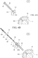
FIGS. 4A and 4B each show a procedure for attaching the vibrometer to the compressor; -
FIG. 5 shows a procedure for attaching the vibrometer to the compressor; -
FIG. 6 is a schematic view illustrating an operation for aligning an axial center of a probe with an axial center of an insertion securing hole in a bearing housing using the attachment; -
FIGS. 7A and 7B each show a procedure for attaching the vibrometer to the compressor; and -
FIG. 8 shows a procedure for attaching the vibrometer to the compressor. - Now, with reference to the accompanying drawings, a vibrometer assembly and a rotating machine according to an embodiment of the present invention will be described.
- In this embodiment, a compressor is shown as an example of a rotating machine including a
vibrometer 20. - A
compressor 1 inFIG. 1 includes arotating shaft 11 to which a compression mechanism (not shown) such as an impeller (a bladed wheel) is coupled, a case 12 (casing) that houses the compression mechanism, and abearing device 10 that supports the rotatingshaft 11. - The
compressor 1 constitutes part of a facility such as a plant. Thecompressor 1 compresses gas introduced from outside into thecase 12 using the compression mechanism and discharges the gas out of thecase 12. - An
end 11A of the horizontally extendingrotating shaft 11 protrudes from one end side of thecase 12, and is supported by thebearing device 10. An opposite end (not shown inFIG. 1 ) of the rotatingshaft 11 also protrudes from the other end side of thecase 12, and is supported by a journal bearing (not shown). - The
bearing device 10 includes a journal bearing 14 that rotatably supports the rotatingshaft 11, a bearinghousing 15 that holds the journal bearing 14,thrust bearings 16 that axially support the rotatingshaft 11, and ahousing 17 that holds thethrust bearings 16. - The journal bearing 14 surrounds an outer periphery of the rotating
shaft 11, and thethrust bearings 16 are arranged on opposite sides of aflange 11C protruding radially outward from the rotatingshaft 11. Thebearings - The
bearing device 10 and a portion of the rotatingshaft 11 protruding from thecase 12 are covered with acover case 121 provided to thecase 12. InFIG. 1 , thecase 12 is not shown cutaway, but only thecover case 121 is shown cutaway. - Since a periphery of the rotating
shaft 11 is sealed so as to prevent the gas in thecase 12 from escaping out of thecase 12, an ambience of the inside of thecover case 121 is the air. - To monitor vibration of the rotating
shaft 11 and make thecompressor 1 stably operate, thecompressor 1 includes avibrometer 20 that measures the vibration of the rotatingshaft 11. - The
vibrometer 20 measures vibration displacement of the rotatingshaft 11 and a position of the rotatingshaft 11 based on the vibration displacement, by using a distance between adistal end 201 close to an outer peripheral surface of the rotatingshaft 11 and the outer peripheral surface of the rotatingshaft 11. Thedistal end 201 of thevibrometer 20 is not in contact with the outer peripheral surface of the rotatingshaft 11. - The
vibrometer 20 is preferably also provided in a housing of the journal bearing (not shown) that supports the end opposite to theend 11A of the rotatingshaft 11. Thevibrometer 20 may be similarly provided in thehousing 17 of thethrust bearings 16. - The
vibrometer 20 and a member assembled to thevibrometer 20 are generally in the form of an elongated rod, and arranged toward the axial center of the rotatingshaft 11 along a radial direction D1 of the bearinghousing 15. To measure vibration displacement in any radial directions, twovibrometers 20 are actually provided and arranged perpendicularly to each other. - This embodiment has a main feature in a configuration of the
vibrometer assembly 2 including thevibrometer 20. - Now, with reference to
FIGS. 2 and3 , the configuration of thevibrometer assembly 2 will be described. Thevibrometer assembly 2 includes, besides thevibrometer 20, part of thecover case 121, part of thebearing housing 15, anattachment 30 and aguide cylinder 40 both for supporting an operation for attaching thevibrometer 20 to thecompressor 1, and an outside securing nut 45 (fixture) that secures theattachment 30 to thecover case 121. - As shown in
FIG. 2 , thevibrometer 20 includes aprobe 21 that measures a distance up to the outer peripheral surface of therotating shaft 11, and a conductor 22 (shown by dot-and-dash line) drawn from theprobe 21. - The
vibrometer 20 may be a known distance measuring sensor that can detect a distance such as an eddy-current type or capacitance type sensor. An electric signal indicating the distance up to the outerperipheral surface 11B of therotating shaft 11, the distance being detected by theprobe 21 made of metal and energized through theconductor 22, is transmitted to a control circuit unit (not shown) through adifferent conductor 22. - As shown in
FIG. 2 , theprobe 21 in this embodiment is linearly formed, and on at least a distal end side of an outer periphery of the probe 21 athread 21A is provided. Theprobe 21 is shorter than a distance between the bearinghousing 15 and thecover case 121. - The bearing
housing 15 has around hole 151 into which theprobe 21 is inserted, and afemale thread 152 continuous with theround hole 151. Thethread 21A on theprobe 21 is screwed into thefemale thread 152 to secure theprobe 21 to the bearinghousing 15. Theprobe 21 protrudes from theround hole 151 radially outward of the bearinghousing 15 while being secured to the bearinghousing 15. - The
round hole 151 and thefemale thread 152 are formed toward the axial center of therotating shaft 11 along the radial direction of the bearinghousing 15. The axial center of theround hole 151 substantially matches the axial center of thefemale thread 152. Theround hole 151 and thefemale thread 152 are collectively referred to as an inside insertion securing hole 150 (an inside securing portion). - When the
probe 21 is secured to the bearinghousing 15, the distal end of the probe 21 (thedistal end 201 of the vibrometer 20) closely faces the outerperipheral surface 11B of therotating shaft 11. - The bearing
housing 15 has arecess 153 recessed from anouter periphery 15A, and anopening 151A of theround hole 151 is located at a bottom of therecess 153. Inside therecess 153, theprobe 21 and theattachment 30 are connected with each other. - Depending on a length of the
probe 21, theattachment 30 and theprobe 21 may be connected outside theouter periphery 15A of the bearinghousing 15. In that case, there is no need for therecess 153, and theround hole 151 may open in theouter periphery 15A. - It is assumed that the
vibrometer 20 and the member assembled to the vibrometer 20 (hereinafter referred to as a complete set of vibrometer 20) are generally arranged inside thecover case 121. In that case, theprobe 21 can be screwed to the bearinghousing 15 by thethread 21A on theprobe 21 and a nut attached to a portion of theprobe 21 protruding from the bearinghousing 15, and theconductor 22 drawn from theprobe 21 can be connected to a terminal (not shown) prepared in thecompressor 1. - If the complete set of
vibrometer 20 is arranged inside thecover case 121, it is necessary to open thecover case 121 to access thevibrometer 20 for attaching or removing thevibrometer 20 in case of a fault or the like of thevibrometer 20. If at least part of thecover case 121 is removed, part of therotating shaft 11 is exposed. Thus, thecompressor 1 in operation needs to be suspended in view of safety. - In view of the above, in this embodiment, without opening the
cover case 121, thevibrometer 20 is passed through a throughhole 122 penetrating thecover case 121 in a thickness direction, and wherein from the outside of thecover case 121, thedistal end 201 of thevibrometer 20 is secured to or removed from the bearinghousing 15. - An operation for inserting the
vibrometer 20 from the outside of thecover case 121 into the throughhole 122 in thecover case 121 and also into the inside of theinsertion securing hole 150 away from the throughhole 122 is difficult, because a position of the insideinsertion securing hole 150 cannot be visually checked, unlike an operation performed while the insideinsertion securing hole 150 is directly visually checked with the openedcover case 121 as described above. When thevibrometer 20 is inserted into the throughhole 122, the insideinsertion securing hole 150 located on an extended line of the throughhole 122 becomes completely invisible. - Of course, the inside insertion securing hole 150 (the
round hole 151 and the female thread 152) and the throughhole 122 are machined so that the axial center of the insideinsertion securing hole 150 matches the axial center of the throughhole 122. Even if theguide cylinder 40 is used to support the operation for inserting thevibrometer 20 into the throughhole 122 and the insideinsertion securing hole 150, that alone does not allow thevibrometer 20 to be smoothly inserted into the insideinsertion securing hole 150 due to errors in machining, errors in assembly of the bearinghousing 15, thecover case 121, and theguide cylinder 40, swing of theprobe 21 inside theguide cylinder 40, or the like. - Particularly, in a case that an insertion length of the
probe 21 into the insideinsertion securing hole 150 is long as in this embodiment, theprobe 21 can be inserted into an innermost part of the insideinsertion securing hole 150 to secure thethread 21A on theprobe 21 to the bearinghousing 15 only when theprobe 21 is inserted straight into the insideinsertion securing hole 150 with the axial center of the insideinsertion securing hole 150 being aligned with the axial center of theprobe 21. - Thus, in this embodiment, as a component for supporting an operation for attaching the
vibrometer 20 to thecompressor 1, an attachment 30 (FIGS. 2 and3 ) connected to theprobe 21 is used in addition to theguide cylinder 40. - The
attachment 30 extends radially outward of the bearinghousing 15 so as to be continuous with theprobe 21, and penetrates the throughhole 122 to reach the outside of thecover case 121. - The
attachment 30 is passed through the inside of theguide cylinder 40 penetrating thecover case 121, and has a plurality of (four here) joints 31 to 34 arranged in a length direction of theguide cylinder 40. - The
attachment 30 at least partially has thejoints 31 to 34 as movable portions that can move the axial center of theprobe 21 to axially align theprobe 21 with the insideinsertion securing hole 150. - The
attachment 30 includes fivecylindrical parts 301 to 305 that form thejoints 31 to 34. Among theparts 301 to 305, the parts adjacent to each other are coupled by pins to form joints bendable around the pins (P1, P2). For example, thepart 301 connected to theprobe 21 and thenext part 302 form the joint 31. - The
parts 301 to 305 are made of any metal material as necessary. - An orientation of the pins P1 in the two
joints joints 31 to 34 is perpendicular to an orientation of the pins P2 in the other twojoints - As shown in
FIGS. 3A to 3C , theparts 301 to 305 each have a pair ofpawls pawls conductor 22 of thevibrometer 20 is passed through a cylindrical space Sp formed inside each of theparts 301 to 305. - The three
parts 302 to 304 are formed to have the same shape as shown inFIG. 3A . Theparts 302 to 304 are coupled so that the pins P1, P2 are alternately oriented. Theparts 302 to 304 do not always need to be alternately coupled. - The part 301 (
FIG. 3B ) coupled to thepart 302 is connected to anend 21B (FIG. 2 ) of theprobe 21 protruding from theround hole 151 radially outward of the bearinghousing 15. Thepart 301 is arranged in therecess 153 in the bearinghousing 15, but not limited to this, and may be arranged outside theouter periphery 15A of the bearinghousing 15. - The
end 21B of theprobe 21 is screwed into afemale thread 301A (FIG. 3B ) formed inside thepart 301, and secured to thepart 301 by adouble nut 301W (FIG. 2 ) for locking. Thedouble nut 301W is rotated to adjust an insertion depth of theprobe 21 into thefemale thread 301A, thereby increasing or decreasing a total length from thedistal end 201 of theprobe 21 to anoutside end 30B of thepart 305. - The part 305 (
FIG. 3C ) coupled to thepart 304 is secured to theguide cylinder 40 by an outside securing nut 45 (FIG. 2 ) provided on an outer periphery of a protruding portion of outward theguide cylinder 40 and thecover case 121.Washers outside securing nut 45 and an upper end of theguide cylinder 40. - The length of the
attachment 30 and the probe 21 (total length) is adjusted to a defined length by thedouble nut 301W so that theprobe 21 is close to therotating shaft 11 so as to be able to accurately detect vibration of therotating shaft 11 and theattachment 30 can be secured to theguide cylinder 40 by the outside securing nut. - It is preferable to take measures to prevent oil for lubricating the journal bearing 14 from flowing from around the rotating
shaft 11 along theconductor 22 in theprobe 21 or flowing through a gap between an inner wall of theguide cylinder 40 and theattachment 30 to leak out of thecover case 121. - Thus, as shown in
FIG. 2 , thevibrometer assembly 2 of this embodiment includes aseal 51, packing 52, a packingretainer 53, and acap 54. - The
seal 51 is an O ring, and theseal 51 is arranged in agroove 305A (FIG. 3C ) annularly formed along an outer periphery of thepart 305, and intermediated in a compressed manner between the outer periphery of thepart 305 and the inner wall of theguide cylinder 40 to seal a radial gap between thepart 305 and theguide cylinder 40. - The packing 52 is mounted to the
outside end 30B so that theconductor 22 exposed from theoutside end 30B of thepart 305 is passed through the packing 52. The packing 52 is pressed by the packingretainer 53 screwed onto amale thread 305B (FIG. 3C ) on thepart 305, and then is brought into close contact with an outer periphery of theconductor 22. - The
cap 54 is mounted to theguide cylinder 40 so as to cover theoutside securing nut 45 and the packingretainer 53. Theconductor 22 is drawn, through the through holes in the packingretainer 53 and thecap 54, to outside thecap 54. - A sealing tape (not shown) is preferably provided between a
cap attaching portion 41 on theguide cylinder 40 and a female thread in thecap 54. The sealing tape is compressed between thecap attaching portion 41 and the female thread both having a tapered shape, to eliminate a gap between thecap 54 and theguide cylinder 40. - Covering with the
cap 54 can protect theattachment 30, theoutside securing nut 45, the packing 52, and the like from external environment, external forces, and the like. - The
cap 54 may be mounted to a cap attaching portion formed on thecover case 121. - To prevent leakage of the lubricant, the packing 52 and either one of the
seal 51 or thecap 54 may be selected. - Next, the guide cylinder 40 (
FIG. 2 ) is formed of a metal material into a cylindrical shape, and radially protrudes from the outside to the inside of thecover case 121 by penetrating the inside of the throughhole 122. Theattachment 30 is inserted into a cylindrical space formed inside theguide cylinder 40 having a certain inner diameter. A predetermined clearance is set between the inner wall of theguide cylinder 40 and theparts 301 to 305 of theattachment 30 so that theattachment 30 and theprobe 21 can be smoothly inserted into theguide cylinder 40. - The
guide cylinder 40 linearly corrects postures of theparts 301 to 305 connected to theprobe 21, and guides theprobe 21 and theattachment 30 up to the position of the insideinsertion securing hole 150 in the bearinghousing 15. - The
part 305 of theattachment 30 is, by theoutside securing nut 45, secured to anend surface 40A at the upper end of theguide cylinder 40 protruding outward of thecover case 121. Thecap attaching portion 41 to which thecap 54 is mounted is formed at an upper portion than aflange 42 formed on an outer periphery of the upper end of theguide cylinder 40. Thecap attaching portion 41 and acase attaching portion 43 described below are formed to be thicker than a portion below thecase attaching portion 43. - The
guide cylinder 40 is secured to thecover case 121 by thecase attaching portion 43 formed on the outer periphery of the lower portion than theflange 42 being screwed into afemale thread 122A that forms the throughhole 122. Theattachment 30 is secured to thecover case 121 through theguide cylinder 40. Theattachment 30 may be directly secured to thecover case 121. - The length of the
guide cylinder 40 is determined so that when theprobe 21 of thevibrometer 20 and theattachment 30 connected to theprobe 21 are inserted from the outside of thecover case 121 into theguide cylinder 40, and thedistal end 201 of theprobe 21 reaches the position of theopening 151A of the insideinsertion securing hole 150, at least part of a cylindrical portion of thepart 301 on the distal end side is located inside the guide cylinder 40 (seeFIG. 5 ). Theguide cylinder 40 may have a longer length as long as theguide cylinder 40 does not interfere with a surrounding member such as the bearinghousing 15. - A procedure for assembling the
vibrometer assembly 2 configured as described above, that is, a procedure for attaching thevibrometer 20 to thecompressor 1 will be described. - First, as shown in
FIG. 4A , theguide cylinder 40 is inserted from the outside of thecover case 121 into the throughhole 122 and placed in the cover case 121 (guide cylinder placing step S1). - The
case attaching portion 43 on theguide cylinder 40 is screwed into thefemale thread 122A in thecover case 121 to secure theguide cylinder 40 to the cover case 121 (FIG. 4B ). - Then, as shown in
FIG. 4B , theprobe 21 of thevibrometer 20 and theattachment 30 assembled to theprobe 21 are inserted from the outside of thecover case 121 into theguide cylinder 40, and thedistal end 201 of theprobe 21 is made to reach the bearing housing 15 (guiding step S2). At this time, thedistal end 201 of theprobe 21 does not always directly enter the insideinsertion securing hole 150 in the bearinghousing 15. -
FIG. 4B does not show theconductor 22.FIGS. 7A and 7B are the same. -
FIG. 5 shows a case where thedistal end 201 of theprobe 21 does not enter the insideinsertion securing hole 150 due to errors in machining or the like of the throughhole 122, the insideinsertion securing hole 150, or theguide cylinder 40. - Before the
distal end 201 of theprobe 21 reaches theopening 151A of the insideinsertion securing hole 150, thepart 301 connected to theprobe 21 is located inside theguide cylinder 40, and thus the posture of theprobe 21 supported by thepart 301 is along the axial center of theguide cylinder 40. Due to this, even if the axial center of the insideinsertion securing hole 150 is not aligned with the axial center of theprobe 21, thedistal end 201 of theprobe 21 is located at an edge of or around theopening 151A. - To insert the
probe 21 in such a state into the insideinsertion securing hole 150, it is necessary to use theattachment 30 to align the axial center of theprobe 21 with the axial center of the inside insertion securing hole 150 (axially aligning step S3). - In this step S3, as schematically shown in
FIG. 6A , thejoints 31 to 34 as the movable portions of theattachment 30 are bent to change the posture (shape) of theattachment 30 inside theguide cylinder 40, to align the axial center of theprobe 21 supported by theattachment 30 with the axial center of the insideinsertion securing hole 150.FIG. 6A shows theadjacent parts 301 to 305 being bent with exaggerated angles. Actually, theparts 301 to 305 are slightly bent within the clearance in theguide cylinder 40.
FIG. 6A shows theattachment 30 being bent by thejoints attachment 30 may be simultaneously bent by thejoints attachment 30 may be bent by at least one of thejoints 31 to 34 to align the axial center of theprobe 21 with the axial center of the insideinsertion securing hole 150. - It is assumed that soon after the
distal end 201 of theprobe 21 reaches the position of theopening 151A of the insideinsertion securing hole 150, the axial center of theprobe 21 is located at a position X shifted from the axial center X0 of the insideinsertion securing hole 150 as shown inFIG. 6B . Then, the posture of theattachment 30 is changed, for example, by thejoints probe 21 as shown by arrow A inFIG. 6B , and the posture of theattachment 30 is changed by thejoints probe 21 to be aligned with the axial center X0 of the insideinsertion securing hole 150.FIG. 6C shows axial centers X, X0 in the direction of VIc inFIG. 6B . - With the
distal end 201 of theprobe 21 butting against the edge of theopening 151A of the inside insertion securing hole 150 (FIG. 5 ), theattachment 30 is pushed or pulled along theguide cylinder 40 or rotated as necessary to perform the axial alignment using theattachment 30 as described above. - The
round hole 151 has a clearance with respect to an outer diameter of theprobe 21, and if the axial center X of theprobe 21 is substantially aligned with the axial center X0 of the insideinsertion securing hole 150, thedistal end 201 of theprobe 21 enters theopening 151A. Thus, thedistal end 201 of theprobe 21 is restrained by a peripheral edge of theopening 151A. - If a
tapered surface 153A (shown by a dot-and-dash line) following a shape of a drill used for machining therecess 153 is formed at the bottom of therecess 153, thetapered surface 153A guides the distal end of theprobe 21 toward a center of theopening 151A. - Then, as shown in
FIG. 7A , theprobe 21 is inserted into an innermost part of the insideinsertion securing hole 150 to secure the distal end of theprobe 21 to the female thread 152 (inside securing step S4). Theattachment 30 is generally moved downward while changing its posture following theprobe 21 inserted, and the state of axial alignment with respect to theprobe 21 and the insideinsertion securing hole 150 is maintained. At this time, theattachment 30 that supports theprobe 21 is held by theguide cylinder 40, and thus theprobe 21 can be stably screwed into thefemale thread 152. Then, theprobe 21 is positioned to create a gap from the outerperipheral surface 11B of therotating shaft 11 while signals such as an eddy current and capacitance are monitored through the conductor 22 (FIG. 2 ) . - Further, as shown in
FIG. 7B , theattachment 30 is secured to the upper end of theguide cylinder 40 using the outside securing nut 45 (outside securing step S5). Thus, theattachment 30 is secured to thecover case 121 through theguide cylinder 40. - Thus, the
vibrometer assembly 2 is completed. - Finally, as shown in
FIG. 8 , the packing 52 is attached to thepart 305 of theattachment 30 using the packingretainer 53, and thecap 54 is mounted to the guide cylinder 40 (lubricant sealing step S6). - By the above, the
compressor 1 having thevibrometer 20 is manufactured. - The
attachment 30 that supports theprobe 21 is held by theguide cylinder 40 while being inserted in theguide cylinder 40, and thevibrometer 20 is supported at two points: at theoutside securing nut 45 and at thefemale thread 152 in the bearinghousing 15. This can ensure sufficient rigidity of theentire vibrometer 20, and reduce natural frequency of thevibrometer 20 to avoid resonance. - When the
vibrometer 20 is removed from thecompressor 1, the operation may be performed in reverse order of the attaching procedure described above, that is, in order from step S6 to S1. - Specifically, after the
cap 54 and the packing 52 are removed, by performing the following steps it is possible to remove the vibrometer 10: a step of releasing theoutside securing nut 45; a step of releasing theprobe 21 from thefemale thread 152 in the bearinghousing 15 by rotating the upper end of theattachment 30 around the axis; and then a step of withdrawing theattachment 30 and theprobe 21 out of theguide cylinder 40. - According to this embodiment, the
vibrometer 20 is supported at two points: at the bearinghousing 15 and at theguide cylinder 40 secured to thecover case 121, and thevibrometer 20 can be attached to or removed from thecompressor 1 by access from the outside of thecover case 121. Thus, thevibrometer 20 can be inspected or exchanged without any trouble to disassemble and open thecover case 121 of thecompressor 1. Since the inside of thecover case 121 in which the bearinghousing 15 is placed is filled with air unlike the inside of a body of thecase 12 that houses the compression mechanism, there is no need to stop the operation of thecompressor 1 for inspecting or exchanging thevibrometer 20. - According to this embodiment, the
guide cylinder 40 and theattachment 30 are provided that support the operation for inserting thevibrometer 20 from the outside of thecover case 121 into the throughhole 122 and the insideinsertion securing hole 150 in the bearinghousing 15 away from the throughhole 122. Thus, theprobe 21 of thevibrometer 20 can be guided up to theopening 151A of the insideinsertion securing hole 150 and theprobe 21 can be accurately axially aligned with the insideinsertion securing hole 150, thereby allowing theprobe 21 to be easily secured to thefemale thread 152 in the bearinghousing 15. - Other than the above, the configurations in the embodiment may be chosen or changed to other configurations without departing from the gist of the present invention.
- The number and the shape of the movable portions of the
attachment 30 are not limited to those in the above embodiment. In the above embodiment, theattachment 30 has the fourjoints 31 to 34 coupled by the pins, but any of the joints may be replaced with a movable joint such as a universal joint. Theattachment 30 may have only three joints coupled by pins although such anattachment 30 has a lower degree of freedom comparing to the above embodiment. - Variants of the
attachment 30 may include, for example, a configuration having twojoints probe 21 with the axial center of the insideinsertion securing hole 150 as in the above embodiment. - In the present invention, the attachment that can support the operation for inserting the probe of the vibrometer may have any configuration as long as the attachment at least partially has a movable portion that can move the axial center of the
probe 21. - For example, instead of the
joints 31 to 34 coupled by the pins, a member such as a tube made of a flexible material like rubber may be used as the movable portion. Alternatively, anattachment 30 generally formed of a rubber tube may be used. - Due to the configuration in which the
parts 301 to 305 having sufficient rigidity to hold their own shapes are coupled by thejoints 31 to 34 as in the above embodiment, the posture of theattachment 30 can be easily changed to an intended posture and the posture can be easily held inside or outside theguide cylinder 40, thereby allowing an axial alignment operation to be efficiently performed. - The vibrometer assembly and the methods for attaching and removing the vibrometer of the present invention can be widely applied to, not limited to the
compressor 1, a rotating machine such as a pump or a blower as long as it includes a rotating shaft, a bearing that supports the rotating shaft, and a case that covers the bearing. - The present invention may be developed to, besides the vibrometer, a sensor or a measuring device that needs to be placed close to a rotating shaft and attached or removed by access from outside a case.
-
- 1
- compressor
- 2
- vibrometer assembly
- 10
- bearing device
- 11
- rotating shaft
- 11A
- end
- 11B
- outer peripheral surface
- 11C
- flange
- 12
- case
- 14
- journal bearing
- 15
- bearing housing
- 15A
- outer periphery
- 16
- thrust bearing
- 17
- housing
- 20
- vibrometer
- 21
- probe
- 21A
- thread
- 21B
- end
- 22
- conductor
- 30
- attachment
- 30B
- outside end
- 30N
- pawl
- 31 to 34
- joint(s) (movable portion(s))
- 40
- guide cylinder
- 40A
- end surface
- 41
- cap attaching portion
- 42
- flange
- 43
- case attaching portion
- 45
- outside securing nut (outside securing portion)
- 51
- seal
- 52
- packing
- 53
- packing retainer
- 54
- cap
- 121
- cover case
- 122
- through hole
- 122A
- female thread
- 150
- insertion hole
- 151
- round hole
- 151A
- opening
- 152
- female thread
- 153
- recess
- 153A
- tapered surface
- 201
- distal end
- 301 to 305
- part(s)
- 301A
- female thread
- 301W
- double nut
- 305A
- groove
- 305B
- male thread
- 451, 452
- washer
- A, B
- arrow
- D1
- radial direction
- P1, P2
- pin(s)
- S1
- guide cylinder placing step
- S2
- guiding step
- S3
- axially aligning step
- S4
- inside securing step
- S5
- outside securing step
- S6
- lubricant sealing step
- Sp
- space
- X, X0
- axis
Claims (10)
- A vibrometer assembly including a vibrometer configured to measure vibration of a rotating shaft, comprising:a probe of the vibrometer that is to be secured to a bearing device that supports the rotating shaft;a guide cylinder that is to be provided to a case so as to penetrate the case and protrude into the case, the case being located outside the bearing device;an attachment that is to be connected to the probe and inserted into the guide cylinder, and at least partially has a movable portion to allow the probe to be axially aligned with an inside securing portion in the bearing device; andan outside securing portion that secures the attachment to the guide cylinder or the case outside the case.
- The vibrometer assembly according to claim 1, wherein the inside securing portion includes a female thread that is provided in a housing of the bearing device to secure the probe, and
the outside securing portion includes a fixture that secures an end of the attachment to the guide cylinder outside the case. - The vibrometer assembly according to claim 1 or 2, wherein the attachment has a plurality of joints arranged in a length direction of the guide cylinder.
- The vibrometer assembly according to claim 3, wherein the attachment has a plurality of parts, the parts adjacent to each other in the length direction forming the plurality of joints by being coupled by pins at least four points, the pins for two of the four points being directed perpendicularly to the pins for the other two points.
- The vibrometer assembly according to any one of claims 1 to 4, wherein a seal is provided to seal a radial gap between the guide cylinder and the attachment.
- The vibrometer assembly according to any one of claims 1 to 5, comprising packing that is provided to the probe so as to be brought into close contact with an outer periphery of a conductor drawn through an inside of the attachment to an outside of the case.
- The vibrometer assembly according to any one of claims 1 to 6, comprising a cap that is to be mounted to the guide cylinder or the case so as to cover the outside securing portion.
- A rotating machine comprising:a vibrometer assembly according to any one of claims 1 to 7;a rotating shaft;a bearing device; anda case.
- A method for attaching a vibrometer configured to measure vibration of a rotating shaft to a rotating machine including the rotating shaft, comprising:a guiding step of inserting a probe of the vibrometer and an attachment connected to the probe from an outside of a case of the rotating machine into the case through a guide cylinder inserted into a through hole in the case, and making a distal end of the probe reach a bearing device that supports the rotating shaft;an axially aligning step of moving a movable portion at least partially included in the attachment to axially align the probe with an inside securing portion in the bearing device;an inside securing step of securing the probe to the bearing device inside the case; andan outside securing step of securing the attachment to the guide cylinder or the case outside the case.
- A method for removing a vibrometer configured to measure vibration of a rotating shaft from a rotating machine including the rotating shaft, comprising:a step of, in a state in which: a probe of the vibrometer connected to an attachment enabled to move a movable portion at least partially included in the attachment is secured to a bearing device that supports the rotating shaft; and the attachment is secured to a case of the rotating machine or a guide cylinder provided to the case to hold the attachment, releasing the attachment from the case or the guide cylinder outside the case;a step of releasing the probe from the bearing device inside the case; anda step of withdrawing the probe and the attachment to an outside of the case.
Applications Claiming Priority (1)
| Application Number | Priority Date | Filing Date | Title |
|---|---|---|---|
| PCT/JP2016/005072 WO2018104981A1 (en) | 2016-12-06 | 2016-12-06 | Vibrometer assembly, rotating machine, and vibrometer attachment method and removal method |
Publications (3)
| Publication Number | Publication Date |
|---|---|
| EP3489640A1 true EP3489640A1 (en) | 2019-05-29 |
| EP3489640A4 EP3489640A4 (en) | 2019-09-25 |
| EP3489640B1 EP3489640B1 (en) | 2020-09-30 |
Family
ID=62491802
Family Applications (1)
| Application Number | Title | Priority Date | Filing Date |
|---|---|---|---|
| EP16923353.3A Active EP3489640B1 (en) | 2016-12-06 | 2016-12-06 | Vibrometer assembly, rotating machine, and vibrometer attachment method and removal method |
Country Status (4)
| Country | Link |
|---|---|
| US (1) | US11150127B2 (en) |
| EP (1) | EP3489640B1 (en) |
| JP (1) | JP6755335B2 (en) |
| WO (1) | WO2018104981A1 (en) |
Cited By (1)
| Publication number | Priority date | Publication date | Assignee | Title |
|---|---|---|---|---|
| US11435264B2 (en) | 2020-01-21 | 2022-09-06 | Mitsubishi Heavy Industries Compressor Corporation | Probe device capable of suppressing damage while also suppressing increase in labor for mounting work |
Families Citing this family (2)
| Publication number | Priority date | Publication date | Assignee | Title |
|---|---|---|---|---|
| CN116818317B (en) * | 2022-11-25 | 2024-01-02 | 山东航行万里汽车轴承有限公司 | Hub bearing test tool |
| US20250244208A1 (en) * | 2024-01-30 | 2025-07-31 | Saudi Arabian Oil Company | Method and apparatus for testing the health of a proximity vibration sensory loop |
Family Cites Families (14)
| Publication number | Priority date | Publication date | Assignee | Title |
|---|---|---|---|---|
| US3859847A (en) * | 1972-09-06 | 1975-01-14 | Westinghouse Electric Corp | Vibration monitoring device using accelerometer to measure displacement |
| US4018083A (en) | 1975-08-22 | 1977-04-19 | General Electric Company | Vibration detection probe holder |
| US4066949A (en) | 1976-09-02 | 1978-01-03 | Carrier Corporation | Probe holder for a machine body position sensor, with means to increase its natural frequency |
| JPS56145322A (en) | 1980-04-14 | 1981-11-12 | Toshiba Corp | Measuring device for vibration of shaft |
| JPH0288126U (en) * | 1988-12-23 | 1990-07-12 | ||
| JP2559329Y2 (en) * | 1991-03-28 | 1998-01-14 | 興亜石油株式会社 | Vibration sensor mounting bracket |
| JP2592405Y2 (en) * | 1992-06-19 | 1999-03-24 | 株式会社東芝 | Vibrometer probe |
| JPH0633032U (en) * | 1992-10-09 | 1994-04-28 | 株式会社東芝 | Vibration meter with integrated probe |
| US6006164A (en) | 1997-07-22 | 1999-12-21 | Skf Condition Monitoring, Inc. | Portable vibration monitor |
| JP3405235B2 (en) | 1998-11-24 | 2003-05-12 | 日本精工株式会社 | Rotational accuracy and dynamic torque measuring device for radial rolling bearings |
| JP2002148005A (en) | 2000-11-13 | 2002-05-22 | Ebara Corp | Liquid-cooled displacement gage in high-temperature liquid |
| JP2005345277A (en) * | 2004-06-03 | 2005-12-15 | Nsk Ltd | Monitoring device and monitoring method |
| JP6485903B2 (en) * | 2015-02-13 | 2019-03-20 | 出光興産株式会社 | Polymerization catalyst for production of aromatic vinyl compound polymer and method for producing aromatic vinyl compound polymer |
| JP6472264B2 (en) | 2015-02-19 | 2019-02-20 | 株式会社テイエルブイ | Sensor device |
-
2016
- 2016-12-06 WO PCT/JP2016/005072 patent/WO2018104981A1/en not_active Ceased
- 2016-12-06 EP EP16923353.3A patent/EP3489640B1/en active Active
- 2016-12-06 US US16/328,436 patent/US11150127B2/en active Active
- 2016-12-06 JP JP2018555319A patent/JP6755335B2/en active Active
Cited By (1)
| Publication number | Priority date | Publication date | Assignee | Title |
|---|---|---|---|---|
| US11435264B2 (en) | 2020-01-21 | 2022-09-06 | Mitsubishi Heavy Industries Compressor Corporation | Probe device capable of suppressing damage while also suppressing increase in labor for mounting work |
Also Published As
| Publication number | Publication date |
|---|---|
| EP3489640B1 (en) | 2020-09-30 |
| US20210293611A1 (en) | 2021-09-23 |
| JP6755335B2 (en) | 2020-09-16 |
| JPWO2018104981A1 (en) | 2019-06-24 |
| US11150127B2 (en) | 2021-10-19 |
| EP3489640A4 (en) | 2019-09-25 |
| WO2018104981A1 (en) | 2018-06-14 |
Similar Documents
| Publication | Publication Date | Title |
|---|---|---|
| US7752726B2 (en) | Fixture and inspection method for an annular seal | |
| EP3489640B1 (en) | Vibrometer assembly, rotating machine, and vibrometer attachment method and removal method | |
| JP5426565B2 (en) | Lubricated screw compressor | |
| US20150260221A1 (en) | Rotary machine, bearing and method for manufacturing a rotary machine | |
| JP7429545B2 (en) | probe device | |
| EP3134617B1 (en) | Subsea sensor assemblies | |
| US20130259646A1 (en) | Dual-Intent Locator Pin and Removable Plug for Gas Turbines | |
| US20200110109A1 (en) | Mechanical seal with sensor | |
| US20170152754A1 (en) | Turbomachine element comprising an auxiliary sealing means, and method for testing this element | |
| US10031331B2 (en) | Inspection apparatus guide system | |
| WO2012114559A1 (en) | Compressor and method for incorporating same | |
| US10612600B2 (en) | Journal bearing, rotary machine, and journal bearing-manufacturing method | |
| JP6212969B2 (en) | mechanical seal | |
| JP6373770B2 (en) | Bolt retaining structure | |
| KR101832244B1 (en) | Bearing Test apparatus for testing behavior of the bearing | |
| JP5195303B2 (en) | Fluid temperature measuring device and protective tube used therefor | |
| US20020145120A1 (en) | Probe for sensing movement | |
| US10563540B2 (en) | Casing for a rotating machine and rotating machine including such casing | |
| KR101789723B1 (en) | Test equipment for monitoring tribological characteristics of Ball bearing | |
| GB2599700A (en) | A subsea pump and method for determining motion of the rotor | |
| KR102557280B1 (en) | Device for measuring the concentricity of non-contact bearing | |
| CN209138124U (en) | The on-Line Monitor Device for preventing rotary drum filter trunnion from damaging | |
| US20210325177A1 (en) | Measuring jig for rotary machine and member management method for rotary machine | |
| CN116429779A (en) | Novel auxiliary device for hole detection of industrial endoscope | |
| CN120292443A (en) | Steam Pipe Leakage Monitoring Device |
Legal Events
| Date | Code | Title | Description |
|---|---|---|---|
| STAA | Information on the status of an ep patent application or granted ep patent |
Free format text: STATUS: THE INTERNATIONAL PUBLICATION HAS BEEN MADE |
|
| PUAI | Public reference made under article 153(3) epc to a published international application that has entered the european phase |
Free format text: ORIGINAL CODE: 0009012 |
|
| STAA | Information on the status of an ep patent application or granted ep patent |
Free format text: STATUS: REQUEST FOR EXAMINATION WAS MADE |
|
| 17P | Request for examination filed |
Effective date: 20190225 |
|
| AK | Designated contracting states |
Kind code of ref document: A1 Designated state(s): AL AT BE BG CH CY CZ DE DK EE ES FI FR GB GR HR HU IE IS IT LI LT LU LV MC MK MT NL NO PL PT RO RS SE SI SK SM TR |
|
| AX | Request for extension of the european patent |
Extension state: BA ME |
|
| A4 | Supplementary search report drawn up and despatched |
Effective date: 20190823 |
|
| RIC1 | Information provided on ipc code assigned before grant |
Ipc: G01M 13/028 20190101ALI20190819BHEP Ipc: G01H 1/00 20060101AFI20190819BHEP Ipc: G01M 13/045 20190101ALI20190819BHEP |
|
| DAV | Request for validation of the european patent (deleted) | ||
| DAX | Request for extension of the european patent (deleted) | ||
| GRAP | Despatch of communication of intention to grant a patent |
Free format text: ORIGINAL CODE: EPIDOSNIGR1 |
|
| STAA | Information on the status of an ep patent application or granted ep patent |
Free format text: STATUS: GRANT OF PATENT IS INTENDED |
|
| INTG | Intention to grant announced |
Effective date: 20200331 |
|
| GRAS | Grant fee paid |
Free format text: ORIGINAL CODE: EPIDOSNIGR3 |
|
| GRAJ | Information related to disapproval of communication of intention to grant by the applicant or resumption of examination proceedings by the epo deleted |
Free format text: ORIGINAL CODE: EPIDOSDIGR1 |
|
| GRAL | Information related to payment of fee for publishing/printing deleted |
Free format text: ORIGINAL CODE: EPIDOSDIGR3 |
|
| STAA | Information on the status of an ep patent application or granted ep patent |
Free format text: STATUS: REQUEST FOR EXAMINATION WAS MADE |
|
| INTC | Intention to grant announced (deleted) | ||
| GRAR | Information related to intention to grant a patent recorded |
Free format text: ORIGINAL CODE: EPIDOSNIGR71 |
|
| STAA | Information on the status of an ep patent application or granted ep patent |
Free format text: STATUS: GRANT OF PATENT IS INTENDED |
|
| GRAA | (expected) grant |
Free format text: ORIGINAL CODE: 0009210 |
|
| STAA | Information on the status of an ep patent application or granted ep patent |
Free format text: STATUS: THE PATENT HAS BEEN GRANTED |
|
| INTG | Intention to grant announced |
Effective date: 20200820 |
|
| AK | Designated contracting states |
Kind code of ref document: B1 Designated state(s): AL AT BE BG CH CY CZ DE DK EE ES FI FR GB GR HR HU IE IS IT LI LT LU LV MC MK MT NL NO PL PT RO RS SE SI SK SM TR |
|
| REG | Reference to a national code |
Ref country code: GB Ref legal event code: FG4D Ref country code: CH Ref legal event code: EP |
|
| REG | Reference to a national code |
Ref country code: AT Ref legal event code: REF Ref document number: 1319280 Country of ref document: AT Kind code of ref document: T Effective date: 20201015 |
|
| REG | Reference to a national code |
Ref country code: DE Ref legal event code: R096 Ref document number: 602016045233 Country of ref document: DE |
|
| REG | Reference to a national code |
Ref country code: IE Ref legal event code: FG4D |
|
| PG25 | Lapsed in a contracting state [announced via postgrant information from national office to epo] |
Ref country code: HR Free format text: LAPSE BECAUSE OF FAILURE TO SUBMIT A TRANSLATION OF THE DESCRIPTION OR TO PAY THE FEE WITHIN THE PRESCRIBED TIME-LIMIT Effective date: 20200930 Ref country code: SE Free format text: LAPSE BECAUSE OF FAILURE TO SUBMIT A TRANSLATION OF THE DESCRIPTION OR TO PAY THE FEE WITHIN THE PRESCRIBED TIME-LIMIT Effective date: 20200930 Ref country code: FI Free format text: LAPSE BECAUSE OF FAILURE TO SUBMIT A TRANSLATION OF THE DESCRIPTION OR TO PAY THE FEE WITHIN THE PRESCRIBED TIME-LIMIT Effective date: 20200930 Ref country code: BG Free format text: LAPSE BECAUSE OF FAILURE TO SUBMIT A TRANSLATION OF THE DESCRIPTION OR TO PAY THE FEE WITHIN THE PRESCRIBED TIME-LIMIT Effective date: 20201230 Ref country code: NO Free format text: LAPSE BECAUSE OF FAILURE TO SUBMIT A TRANSLATION OF THE DESCRIPTION OR TO PAY THE FEE WITHIN THE PRESCRIBED TIME-LIMIT Effective date: 20201230 Ref country code: GR Free format text: LAPSE BECAUSE OF FAILURE TO SUBMIT A TRANSLATION OF THE DESCRIPTION OR TO PAY THE FEE WITHIN THE PRESCRIBED TIME-LIMIT Effective date: 20201231 |
|
| REG | Reference to a national code |
Ref country code: AT Ref legal event code: MK05 Ref document number: 1319280 Country of ref document: AT Kind code of ref document: T Effective date: 20200930 |
|
| PG25 | Lapsed in a contracting state [announced via postgrant information from national office to epo] |
Ref country code: RS Free format text: LAPSE BECAUSE OF FAILURE TO SUBMIT A TRANSLATION OF THE DESCRIPTION OR TO PAY THE FEE WITHIN THE PRESCRIBED TIME-LIMIT Effective date: 20200930 Ref country code: LV Free format text: LAPSE BECAUSE OF FAILURE TO SUBMIT A TRANSLATION OF THE DESCRIPTION OR TO PAY THE FEE WITHIN THE PRESCRIBED TIME-LIMIT Effective date: 20200930 |
|
| REG | Reference to a national code |
Ref country code: NL Ref legal event code: MP Effective date: 20200930 |
|
| REG | Reference to a national code |
Ref country code: LT Ref legal event code: MG4D |
|
| PG25 | Lapsed in a contracting state [announced via postgrant information from national office to epo] |
Ref country code: LT Free format text: LAPSE BECAUSE OF FAILURE TO SUBMIT A TRANSLATION OF THE DESCRIPTION OR TO PAY THE FEE WITHIN THE PRESCRIBED TIME-LIMIT Effective date: 20200930 Ref country code: CZ Free format text: LAPSE BECAUSE OF FAILURE TO SUBMIT A TRANSLATION OF THE DESCRIPTION OR TO PAY THE FEE WITHIN THE PRESCRIBED TIME-LIMIT Effective date: 20200930 Ref country code: RO Free format text: LAPSE BECAUSE OF FAILURE TO SUBMIT A TRANSLATION OF THE DESCRIPTION OR TO PAY THE FEE WITHIN THE PRESCRIBED TIME-LIMIT Effective date: 20200930 Ref country code: PT Free format text: LAPSE BECAUSE OF FAILURE TO SUBMIT A TRANSLATION OF THE DESCRIPTION OR TO PAY THE FEE WITHIN THE PRESCRIBED TIME-LIMIT Effective date: 20210201 Ref country code: SM Free format text: LAPSE BECAUSE OF FAILURE TO SUBMIT A TRANSLATION OF THE DESCRIPTION OR TO PAY THE FEE WITHIN THE PRESCRIBED TIME-LIMIT Effective date: 20200930 Ref country code: EE Free format text: LAPSE BECAUSE OF FAILURE TO SUBMIT A TRANSLATION OF THE DESCRIPTION OR TO PAY THE FEE WITHIN THE PRESCRIBED TIME-LIMIT Effective date: 20200930 |
|
| PG25 | Lapsed in a contracting state [announced via postgrant information from national office to epo] |
Ref country code: ES Free format text: LAPSE BECAUSE OF FAILURE TO SUBMIT A TRANSLATION OF THE DESCRIPTION OR TO PAY THE FEE WITHIN THE PRESCRIBED TIME-LIMIT Effective date: 20200930 Ref country code: AT Free format text: LAPSE BECAUSE OF FAILURE TO SUBMIT A TRANSLATION OF THE DESCRIPTION OR TO PAY THE FEE WITHIN THE PRESCRIBED TIME-LIMIT Effective date: 20200930 Ref country code: AL Free format text: LAPSE BECAUSE OF FAILURE TO SUBMIT A TRANSLATION OF THE DESCRIPTION OR TO PAY THE FEE WITHIN THE PRESCRIBED TIME-LIMIT Effective date: 20200930 Ref country code: PL Free format text: LAPSE BECAUSE OF FAILURE TO SUBMIT A TRANSLATION OF THE DESCRIPTION OR TO PAY THE FEE WITHIN THE PRESCRIBED TIME-LIMIT Effective date: 20200930 Ref country code: IS Free format text: LAPSE BECAUSE OF FAILURE TO SUBMIT A TRANSLATION OF THE DESCRIPTION OR TO PAY THE FEE WITHIN THE PRESCRIBED TIME-LIMIT Effective date: 20210130 |
|
| PG25 | Lapsed in a contracting state [announced via postgrant information from national office to epo] |
Ref country code: NL Free format text: LAPSE BECAUSE OF FAILURE TO SUBMIT A TRANSLATION OF THE DESCRIPTION OR TO PAY THE FEE WITHIN THE PRESCRIBED TIME-LIMIT Effective date: 20200930 Ref country code: SK Free format text: LAPSE BECAUSE OF FAILURE TO SUBMIT A TRANSLATION OF THE DESCRIPTION OR TO PAY THE FEE WITHIN THE PRESCRIBED TIME-LIMIT Effective date: 20200930 |
|
| REG | Reference to a national code |
Ref country code: DE Ref legal event code: R097 Ref document number: 602016045233 Country of ref document: DE |
|
| REG | Reference to a national code |
Ref country code: CH Ref legal event code: PL |
|
| PLBE | No opposition filed within time limit |
Free format text: ORIGINAL CODE: 0009261 |
|
| STAA | Information on the status of an ep patent application or granted ep patent |
Free format text: STATUS: NO OPPOSITION FILED WITHIN TIME LIMIT |
|
| GBPC | Gb: european patent ceased through non-payment of renewal fee |
Effective date: 20201230 |
|
| PG25 | Lapsed in a contracting state [announced via postgrant information from national office to epo] |
Ref country code: MC Free format text: LAPSE BECAUSE OF FAILURE TO SUBMIT A TRANSLATION OF THE DESCRIPTION OR TO PAY THE FEE WITHIN THE PRESCRIBED TIME-LIMIT Effective date: 20200930 Ref country code: DK Free format text: LAPSE BECAUSE OF FAILURE TO SUBMIT A TRANSLATION OF THE DESCRIPTION OR TO PAY THE FEE WITHIN THE PRESCRIBED TIME-LIMIT Effective date: 20200930 |
|
| REG | Reference to a national code |
Ref country code: BE Ref legal event code: MM Effective date: 20201231 |
|
| 26N | No opposition filed |
Effective date: 20210701 |
|
| PG25 | Lapsed in a contracting state [announced via postgrant information from national office to epo] |
Ref country code: IE Free format text: LAPSE BECAUSE OF NON-PAYMENT OF DUE FEES Effective date: 20201206 Ref country code: FR Free format text: LAPSE BECAUSE OF NON-PAYMENT OF DUE FEES Effective date: 20201231 Ref country code: LU Free format text: LAPSE BECAUSE OF NON-PAYMENT OF DUE FEES Effective date: 20201206 |
|
| PG25 | Lapsed in a contracting state [announced via postgrant information from national office to epo] |
Ref country code: SI Free format text: LAPSE BECAUSE OF FAILURE TO SUBMIT A TRANSLATION OF THE DESCRIPTION OR TO PAY THE FEE WITHIN THE PRESCRIBED TIME-LIMIT Effective date: 20200930 Ref country code: CH Free format text: LAPSE BECAUSE OF NON-PAYMENT OF DUE FEES Effective date: 20201231 Ref country code: GB Free format text: LAPSE BECAUSE OF NON-PAYMENT OF DUE FEES Effective date: 20201230 Ref country code: LI Free format text: LAPSE BECAUSE OF NON-PAYMENT OF DUE FEES Effective date: 20201231 |
|
| PG25 | Lapsed in a contracting state [announced via postgrant information from national office to epo] |
Ref country code: IS Free format text: LAPSE BECAUSE OF FAILURE TO SUBMIT A TRANSLATION OF THE DESCRIPTION OR TO PAY THE FEE WITHIN THE PRESCRIBED TIME-LIMIT Effective date: 20210130 Ref country code: TR Free format text: LAPSE BECAUSE OF FAILURE TO SUBMIT A TRANSLATION OF THE DESCRIPTION OR TO PAY THE FEE WITHIN THE PRESCRIBED TIME-LIMIT Effective date: 20200930 Ref country code: MT Free format text: LAPSE BECAUSE OF FAILURE TO SUBMIT A TRANSLATION OF THE DESCRIPTION OR TO PAY THE FEE WITHIN THE PRESCRIBED TIME-LIMIT Effective date: 20200930 Ref country code: CY Free format text: LAPSE BECAUSE OF FAILURE TO SUBMIT A TRANSLATION OF THE DESCRIPTION OR TO PAY THE FEE WITHIN THE PRESCRIBED TIME-LIMIT Effective date: 20200930 |
|
| PG25 | Lapsed in a contracting state [announced via postgrant information from national office to epo] |
Ref country code: MK Free format text: LAPSE BECAUSE OF FAILURE TO SUBMIT A TRANSLATION OF THE DESCRIPTION OR TO PAY THE FEE WITHIN THE PRESCRIBED TIME-LIMIT Effective date: 20200930 |
|
| PG25 | Lapsed in a contracting state [announced via postgrant information from national office to epo] |
Ref country code: BE Free format text: LAPSE BECAUSE OF NON-PAYMENT OF DUE FEES Effective date: 20201231 |
|
| PGFP | Annual fee paid to national office [announced via postgrant information from national office to epo] |
Ref country code: DE Payment date: 20251028 Year of fee payment: 10 |
|
| PGFP | Annual fee paid to national office [announced via postgrant information from national office to epo] |
Ref country code: IT Payment date: 20251121 Year of fee payment: 10 |