EP3489607A1 - Heat transfer plate for plate-and-shell heat exchanger and plate-and-shell heat exchanger with the same - Google Patents
Heat transfer plate for plate-and-shell heat exchanger and plate-and-shell heat exchanger with the same Download PDFInfo
- Publication number
- EP3489607A1 EP3489607A1 EP18200293.1A EP18200293A EP3489607A1 EP 3489607 A1 EP3489607 A1 EP 3489607A1 EP 18200293 A EP18200293 A EP 18200293A EP 3489607 A1 EP3489607 A1 EP 3489607A1
- Authority
- EP
- European Patent Office
- Prior art keywords
- plate
- heat transfer
- shell
- plate body
- projections
- Prior art date
- Legal status (The legal status is an assumption and is not a legal conclusion. Google has not performed a legal analysis and makes no representation as to the accuracy of the status listed.)
- Withdrawn
Links
Images




Classifications
-
- F—MECHANICAL ENGINEERING; LIGHTING; HEATING; WEAPONS; BLASTING
- F28—HEAT EXCHANGE IN GENERAL
- F28D—HEAT-EXCHANGE APPARATUS, NOT PROVIDED FOR IN ANOTHER SUBCLASS, IN WHICH THE HEAT-EXCHANGE MEDIA DO NOT COME INTO DIRECT CONTACT
- F28D9/00—Heat-exchange apparatus having stationary plate-like or laminated conduit assemblies for both heat-exchange media, the media being in contact with different sides of a conduit wall
- F28D9/0062—Heat-exchange apparatus having stationary plate-like or laminated conduit assemblies for both heat-exchange media, the media being in contact with different sides of a conduit wall the conduits for one heat-exchange medium being formed by spaced plates with inserted elements
- F28D9/0068—Heat-exchange apparatus having stationary plate-like or laminated conduit assemblies for both heat-exchange media, the media being in contact with different sides of a conduit wall the conduits for one heat-exchange medium being formed by spaced plates with inserted elements with means for changing flow direction of one heat exchange medium, e.g. using deflecting zones
-
- F—MECHANICAL ENGINEERING; LIGHTING; HEATING; WEAPONS; BLASTING
- F28—HEAT EXCHANGE IN GENERAL
- F28D—HEAT-EXCHANGE APPARATUS, NOT PROVIDED FOR IN ANOTHER SUBCLASS, IN WHICH THE HEAT-EXCHANGE MEDIA DO NOT COME INTO DIRECT CONTACT
- F28D9/00—Heat-exchange apparatus having stationary plate-like or laminated conduit assemblies for both heat-exchange media, the media being in contact with different sides of a conduit wall
- F28D9/0031—Heat-exchange apparatus having stationary plate-like or laminated conduit assemblies for both heat-exchange media, the media being in contact with different sides of a conduit wall the conduits for one heat-exchange medium being formed by paired plates touching each other
- F28D9/0043—Heat-exchange apparatus having stationary plate-like or laminated conduit assemblies for both heat-exchange media, the media being in contact with different sides of a conduit wall the conduits for one heat-exchange medium being formed by paired plates touching each other the plates having openings therein for circulation of at least one heat-exchange medium from one conduit to another
-
- F—MECHANICAL ENGINEERING; LIGHTING; HEATING; WEAPONS; BLASTING
- F28—HEAT EXCHANGE IN GENERAL
- F28D—HEAT-EXCHANGE APPARATUS, NOT PROVIDED FOR IN ANOTHER SUBCLASS, IN WHICH THE HEAT-EXCHANGE MEDIA DO NOT COME INTO DIRECT CONTACT
- F28D9/00—Heat-exchange apparatus having stationary plate-like or laminated conduit assemblies for both heat-exchange media, the media being in contact with different sides of a conduit wall
-
- F—MECHANICAL ENGINEERING; LIGHTING; HEATING; WEAPONS; BLASTING
- F28—HEAT EXCHANGE IN GENERAL
- F28D—HEAT-EXCHANGE APPARATUS, NOT PROVIDED FOR IN ANOTHER SUBCLASS, IN WHICH THE HEAT-EXCHANGE MEDIA DO NOT COME INTO DIRECT CONTACT
- F28D9/00—Heat-exchange apparatus having stationary plate-like or laminated conduit assemblies for both heat-exchange media, the media being in contact with different sides of a conduit wall
- F28D9/0006—Heat-exchange apparatus having stationary plate-like or laminated conduit assemblies for both heat-exchange media, the media being in contact with different sides of a conduit wall the plate-like or laminated conduits being enclosed within a pressure vessel
-
- F—MECHANICAL ENGINEERING; LIGHTING; HEATING; WEAPONS; BLASTING
- F28—HEAT EXCHANGE IN GENERAL
- F28D—HEAT-EXCHANGE APPARATUS, NOT PROVIDED FOR IN ANOTHER SUBCLASS, IN WHICH THE HEAT-EXCHANGE MEDIA DO NOT COME INTO DIRECT CONTACT
- F28D9/00—Heat-exchange apparatus having stationary plate-like or laminated conduit assemblies for both heat-exchange media, the media being in contact with different sides of a conduit wall
- F28D9/0012—Heat-exchange apparatus having stationary plate-like or laminated conduit assemblies for both heat-exchange media, the media being in contact with different sides of a conduit wall the apparatus having an annular form
-
- F—MECHANICAL ENGINEERING; LIGHTING; HEATING; WEAPONS; BLASTING
- F28—HEAT EXCHANGE IN GENERAL
- F28D—HEAT-EXCHANGE APPARATUS, NOT PROVIDED FOR IN ANOTHER SUBCLASS, IN WHICH THE HEAT-EXCHANGE MEDIA DO NOT COME INTO DIRECT CONTACT
- F28D9/00—Heat-exchange apparatus having stationary plate-like or laminated conduit assemblies for both heat-exchange media, the media being in contact with different sides of a conduit wall
- F28D9/0012—Heat-exchange apparatus having stationary plate-like or laminated conduit assemblies for both heat-exchange media, the media being in contact with different sides of a conduit wall the apparatus having an annular form
- F28D9/0018—Heat-exchange apparatus having stationary plate-like or laminated conduit assemblies for both heat-exchange media, the media being in contact with different sides of a conduit wall the apparatus having an annular form without any annular circulation of the heat exchange media
-
- F—MECHANICAL ENGINEERING; LIGHTING; HEATING; WEAPONS; BLASTING
- F28—HEAT EXCHANGE IN GENERAL
- F28F—DETAILS OF HEAT-EXCHANGE AND HEAT-TRANSFER APPARATUS, OF GENERAL APPLICATION
- F28F21/00—Constructions of heat-exchange apparatus characterised by the selection of particular materials
- F28F21/08—Constructions of heat-exchange apparatus characterised by the selection of particular materials of metal
- F28F21/081—Heat exchange elements made from metals or metal alloys
- F28F21/082—Heat exchange elements made from metals or metal alloys from steel or ferrous alloys
- F28F21/083—Heat exchange elements made from metals or metal alloys from steel or ferrous alloys from stainless steel
-
- F—MECHANICAL ENGINEERING; LIGHTING; HEATING; WEAPONS; BLASTING
- F28—HEAT EXCHANGE IN GENERAL
- F28F—DETAILS OF HEAT-EXCHANGE AND HEAT-TRANSFER APPARATUS, OF GENERAL APPLICATION
- F28F3/00—Plate-like or laminated elements; Assemblies of plate-like or laminated elements
- F28F3/08—Elements constructed for building-up into stacks, e.g. capable of being taken apart for cleaning
-
- F—MECHANICAL ENGINEERING; LIGHTING; HEATING; WEAPONS; BLASTING
- F28—HEAT EXCHANGE IN GENERAL
- F28F—DETAILS OF HEAT-EXCHANGE AND HEAT-TRANSFER APPARATUS, OF GENERAL APPLICATION
- F28F9/00—Casings; Header boxes; Auxiliary supports for elements; Auxiliary members within casings
- F28F9/005—Other auxiliary members within casings, e.g. internal filling means or sealing means
Definitions
- Embodiments of the present disclosure relates to a heat transfer plate for a plate-and-shell heat exchanger and a plate-and-shell heat exchanger.
- a typical plate-and-shell heat exchanger comprises a shell and a plurality of heat transfer plates stacked on a top of each other in the cavity of the shell.
- the heat transfer plates are formed with patterns such that first and second flow paths respectively formed between the neighboring heat transfer plates are alternately arranged in a direction perpendicular to the heat transfer plates.
- the shell comprises: a peripheral wall; a first inlet port and a first outlet port formed in the peripheral wall; an end wall; and a second inlet port and a second outlet port formed in the end wall.
- first fluid When first fluid enters the shell from the first inlet port, it tends to bypass central regions of the heat transfer plates where the patterns are formed, and to flow from the first inlet port to the first outlet port along peripheries of the heat transfer plates since a flow resistance along the peripheries of the heat transfer plates is lower than that of the central regions of the heat transfer plates where the patterns are formed, thereby resulting in a non-uniform distribution of the first fluid.
- the present disclosure provides a heat transfer plate for a plate-and-shell heat exchanger and a plate-and-shell heat exchanger that at least partly alleviate the non-uniform distribution of the first fluid.
- Embodiments of the present disclosure provide a heat transfer plate for a plate-and-shell heat exchanger.
- the heat transfer plate comprises: a plate body having first and second sides opposite to each other in a direction perpendicular to the plate body; and a projection protruding from the plate body in a direction from the first side towards the second side, extending along a segment of a periphery of the plate body, and having a first end and a second end.
- the projection comprises two projections each extending along a segment of the periphery of the plate body, and the heat transfer plate further comprises: a first gap formed between the first ends of the two projections to form a first inlet; and a second gap formed between the second ends of the two projections to form a first outlet.
- the plate body has an essentially circular shape, and the projection extends along a curved line or an arc.
- the projection is spaced away from the periphery of the plate body.
- the heat transfer plate further comprises: a blocking protrusion protruding from the plate body in the direction from the first side towards the second side, and extending from the projection to the periphery of the plate body.
- each of a first distance between the first ends of the two projections and a second distance between the second ends of the two projections is less than a length of each of the two projections, or 1/2 of the length of each of the two projections.
- the plate body has an essentially circular shape, and a central angle corresponding to the projection is greater than 90 or 120 degrees.
- a first distance between the first ends of the two projections is greater than a second distance between the second ends of the two projections.
- the heat transfer plate further comprises: a first opening formed in the plate body to form a second inlet; and a second opening formed in the plate body to form a second outlet.
- One of the first inlet and the first outlet, and one of the second inlet and the second outlet are located on one of two sides opposite in a direction parallel to the plate body, while the other of the first inlet and the first outlet, and the other of the second inlet and the second outlet are located on the other of the two sides.
- the first inlet and the second inlet are located on one of the two sides, while the first outlet and the second outlet are located on the other of the two sides.
- each of the two projections extends continuously.
- Embodiments of the present disclosure also provide a plate-and-shell heat exchanger.
- the plate-and-shell heat exchanger comprises: a shell defining a cavity; and a plurality of heat transfer plates mentioned above, which are stacked on a top of each other in the cavity of the shell.
- the shell comprises a peripheral wall extending in a peripheral direction around the plurality of heat transfer plates, and a first inlet port and a first outlet port which are formed in the peripheral wall
- the plate-and-shell heat exchanger further comprises: a blocking piece located between an inner wall surface of the peripheral wall of the shell and the plate bodies of the plurality of heat transfer plates, and between the first inlet port and the first outlet port in the peripheral direction.
- the blocking piece abuts against the projection of each of the plurality of heat transfer plates.
- the blocking piece is made of stainless steel.
- a plate-and-shell heat exchanger 100 comprises: a shell 50 defining a cavity 51; and a plurality of heat transfer plates 10 which are stacked on a top of each other in the cavity 51 of the shell 50.
- the shell 50 may have a cylindrical shape or any other appropriate shape.
- the shell 50 comprises a peripheral wall 52 extending in a peripheral direction around the plurality of heat transfer plates 10, and a first inlet port 61 and a first outlet port 62 which are formed in the peripheral wall 52.
- the shell 50 further comprises an end wall 53 such as a cover, and a second inlet port 71 and a second outlet port 72 which are formed in the end wall 53.
- the heat transfer plates 10 are formed with patterns such that first flow paths 81 and second flow paths 82 respectively formed between the neighboring heat transfer plates 10 are alternately arranged in a direction perpendicular to the heat transfer plates 10 or an axial direction of the shell 50.
- Sealing pieces 91 are formed around the openings 21 and 22 of the heat transfer plates 10, and sealing pieces 92 are formed around peripheries 115 of the heat transfer plates 10 so that first fluid 102 enters the first flow paths 81 through the first inlet port 61 and flows out of the plate-and-shell heat exchanger 100 through the first outlet port 62, while second fluid 103 enters the second flow paths 82 through the second inlet port 71 and flows out of the plate-and-shell heat exchanger 100 through the second outlet port 72.
- the heat transfer plate 10 comprises: a plate body 11 having first and second sides 111, 112 opposite to each other in a direction perpendicular to the plate body 11; and a projection 12 protruding from the plate body 11 in a direction from the first side 111 towards the second side 112, extending along a segment 115S of a periphery 115 of the plate body 11, and having a first end 121 and a second end 122.
- the projection 12 may be spaced away from the periphery 115 of the plate body 11.
- the projection 12 comprises two projections 12 each extending along a segment 115S of the periphery 115 of the plate body 11, and the heat transfer plate 10 further comprises: a first gap 131 formed between the first ends 121 of the two projections 12 to form a first inlet 131P for the first fluid 102; and a second gap 132 formed between the second ends 122 of the two projections 12 to form a first outlet 132P for the first fluid 102.
- Each of the two projections 12 may extend continuously. With the projections 12 according to the embodiments, the projections 12 partly encircle the central region 101 and form a barrier along these peripheral sections of the heat transfer plates 10 when they are connected together.
- first fluid 102 is prevented from entering the regions between the projections 12 and the periphery 115 of the plate body 11 of the heat transfer plates 10, and is forced to flow through the central region 101 from the first inlet 131P to the first outlet 132P.
- bypass flow 102B along the periphery 115 of the plate body 11 of the heat transfer plates 10 or between one or both of the projections 12 and the periphery 115 of the plate body 11 of the heat transfer plates 10, but the bypass flow 102B will improve the heat exchanging efficiency of the plate-and-shell heat exchanger 100.
- the plate body 11 has an essentially circular shape, and the projection 12 extends along a curved line or an arc.
- the plate body 11 may have an essentially elliptical shape, an essentially rectangular shape, or the like, while the projection 12 may extend along a segment of an ellipse, a straight line, or the like.
- the heat transfer plate 10 may further comprises: a blocking protrusion 15 protruding from the plate body 11 in the direction from the first side 111 towards the second side 112, and extending from the projection 12 to the periphery 115 of the plate body 11.
- the plate-and-shell heat exchanger 100 may further comprises a blocking piece 16 located between an inner wall surface 56 of the peripheral wall 52 of the shell 50 and the plate bodies 11 of the plurality of heat transfer plates 10, and between the first inlet port 61 and the first outlet port 62 in the peripheral direction.
- the blocking piece 16 may abut against the projection 12 of each of the plurality of heat transfer plates 10.
- the blocking piece 16 may be made of stainless steel.
- the blocking piece 16 has a comb shape.
- the blocking piece 16 is a separate element from the heat transfer plate 10.
- the blocking protrusion 15 and the blocking piece 16 are short than the projection 12 in the peripheral direction.
- lengths of the blocking protrusion 15 and the blocking piece 16 in the peripheral direction are less than 1/10, 1/15 or the like of a length of the projection 12 in the peripheral direction.
- the heat transfer plate 10 comprises one projection 12.
- the plate-and-shell heat exchanger 100 further comprises a sealing member 17 on a side of the heat transfer plates 10 where no projections 12 are provided.
- FIG. 5 show one blocking protrusion 15 on one side, and one blocking piece 16 on the other side, two blocking protrusions 15, two blocking pieces 16, or two sealing members 17 may be disposed on the two sides, respectively; one sealing member 17 and one blocking protrusion 15 may be disposed on the two sides, respectively; or one sealing member 17 and one blocking piece 16 may be disposed on the two sides, respectively.
- the heat transfer plate 10 comprises: one projection 12.
- the plate-and-shell heat exchanger 100 further comprises a sealing member 17 on a side of the heat transfer plates 10 where no projections 12 are provided.
- each of a first distance between the first ends 121 of the two projections 12 and a second distance between the second ends 122 of the two projections 12 may be less than a length of each of the two projections 12, or 1/2 of the length of each of the two projections 12.
- the plate body 11 has an essentially circular shape, and a central angle corresponding to the projection 12 is greater than 90 or 120 degrees or the like, so that the projection 12 has an enough length to prevent the first fluid 102 from bypassing a central region 101 of the heat transfer plate 10.
- the first distance between the first ends 121 of the two projections 12 may be greater than the second distance between the second ends 122 of the two projections 12.
- the sealing member 17 may have substantially the same length as the projection 12. For example, a central angle corresponding to the sealing member 17 is greater than 90 or 120 degrees or the like, so that the sealing member 17 has an enough length in the peripheral direction to prevent the first fluid from bypassing the central region 101 of the heat transfer plate 10.
- the blocking protrusion 15, the blocking piece 16 and/or the sealing member 17 can at least partly alleviate the bypass flow 102B along the periphery 115 of the plate body 11 of the heat transfer plates 10 or between one or both projections 12 and the periphery 115 of the plate body 11 of the heat transfer plates 10.
- the heat transfer plate 10 further comprises: a first opening 21 formed in the plate body 11 to form a second inlet 21P for the second fluid 103; and a second opening 22 formed in the plate body 11 to form a second outlet 22P for the second fluid 103.
- One of the first inlet 131P and the first outlet 132P, and one of the second inlet 21P and the second outlet 22P are located on one of two sides 113, 114 opposite in a direction parallel to the plate body 11, while the other of the first inlet 131P and the first outlet 132P, and the other of the second inlet 21P and the second outlet 22P are located on the other of the two sides 113, 114.
- first inlet 131P and the second inlet 21P are located on one (for example an upper side) of the two sides 113, 114, while the first outlet 132P and the second outlet 22P are located on the other (for example a lower side) of the two sides 113, 114.
- the non-uniform distribution of the first fluid 102 can be at least partly alleviated.
Landscapes
- Engineering & Computer Science (AREA)
- Physics & Mathematics (AREA)
- Thermal Sciences (AREA)
- Mechanical Engineering (AREA)
- General Engineering & Computer Science (AREA)
- Heat-Exchange Devices With Radiators And Conduit Assemblies (AREA)
Abstract
Description
- Embodiments of the present disclosure relates to a heat transfer plate for a plate-and-shell heat exchanger and a plate-and-shell heat exchanger.
- A typical plate-and-shell heat exchanger comprises a shell and a plurality of heat transfer plates stacked on a top of each other in the cavity of the shell. The heat transfer plates are formed with patterns such that first and second flow paths respectively formed between the neighboring heat transfer plates are alternately arranged in a direction perpendicular to the heat transfer plates. The shell comprises: a peripheral wall; a first inlet port and a first outlet port formed in the peripheral wall; an end wall; and a second inlet port and a second outlet port formed in the end wall. When first fluid enters the shell from the first inlet port, it tends to bypass central regions of the heat transfer plates where the patterns are formed, and to flow from the first inlet port to the first outlet port along peripheries of the heat transfer plates since a flow resistance along the peripheries of the heat transfer plates is lower than that of the central regions of the heat transfer plates where the patterns are formed, thereby resulting in a non-uniform distribution of the first fluid.
- The present disclosure provides a heat transfer plate for a plate-and-shell heat exchanger and a plate-and-shell heat exchanger that at least partly alleviate the non-uniform distribution of the first fluid.
- Embodiments of the present disclosure provide a heat transfer plate for a plate-and-shell heat exchanger. The heat transfer plate comprises: a plate body having first and second sides opposite to each other in a direction perpendicular to the plate body; and a projection protruding from the plate body in a direction from the first side towards the second side, extending along a segment of a periphery of the plate body, and having a first end and a second end.
- According to embodiments of the present disclosure, the projection comprises two projections each extending along a segment of the periphery of the plate body, and the heat transfer plate further comprises: a first gap formed between the first ends of the two projections to form a first inlet; and a second gap formed between the second ends of the two projections to form a first outlet.
- According to embodiments of the present disclosure, the plate body has an essentially circular shape, and the projection extends along a curved line or an arc.
- According to embodiments of the present disclosure, the projection is spaced away from the periphery of the plate body.
- According to embodiments of the present disclosure, the heat transfer plate further comprises: a blocking protrusion protruding from the plate body in the direction from the first side towards the second side, and extending from the projection to the periphery of the plate body.
- According to embodiments of the present disclosure, each of a first distance between the first ends of the two projections and a second distance between the second ends of the two projections is less than a length of each of the two projections, or 1/2 of the length of each of the two projections.
- According to embodiments of the present disclosure, the plate body has an essentially circular shape, and a central angle corresponding to the projection is greater than 90 or 120 degrees.
- According to embodiments of the present disclosure, a first distance between the first ends of the two projections is greater than a second distance between the second ends of the two projections.
- According to embodiments of the present disclosure, the heat transfer plate further comprises: a first opening formed in the plate body to form a second inlet; and a second opening formed in the plate body to form a second outlet. One of the first inlet and the first outlet, and one of the second inlet and the second outlet are located on one of two sides opposite in a direction parallel to the plate body, while the other of the first inlet and the first outlet, and the other of the second inlet and the second outlet are located on the other of the two sides.
- According to embodiments of the present disclosure, the first inlet and the second inlet are located on one of the two sides, while the first outlet and the second outlet are located on the other of the two sides.
- According to embodiments of the present disclosure, each of the two projections extends continuously.
- Embodiments of the present disclosure also provide a plate-and-shell heat exchanger. The plate-and-shell heat exchanger comprises: a shell defining a cavity; and a plurality of heat transfer plates mentioned above, which are stacked on a top of each other in the cavity of the shell.
- According to embodiments of the present disclosure, the shell comprises a peripheral wall extending in a peripheral direction around the plurality of heat transfer plates, and a first inlet port and a first outlet port which are formed in the peripheral wall, and the plate-and-shell heat exchanger further comprises: a blocking piece located between an inner wall surface of the peripheral wall of the shell and the plate bodies of the plurality of heat transfer plates, and between the first inlet port and the first outlet port in the peripheral direction.
- According to embodiments of the present disclosure, the blocking piece abuts against the projection of each of the plurality of heat transfer plates.
- According to embodiments of the present disclosure, the blocking piece is made of stainless steel.
- These and other objects, features and advantages of the present disclosure will become apparent in light of the detailed description of embodiments thereof, as illustrated in the accompanying drawings.
-
-
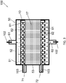
FIG. 1 is a schematic diagram of a plate-and-shell heat exchanger according to an embodiment; -
FIG. 2 is a schematic diagram showing heat transfer plates of the plate-and-shell heat exchanger ofFIG 1 ; -
FIG. 3 is a schematic diagram showing an internal structure of the plate-and-shell heat exchanger ofFIG 1 ; -
FIG. 4 is a schematic diagram of a heat transfer plate according to an embodiment of the present disclosure; and -
FIG. 5 is a schematic diagram of a heat transfer plate according to another embodiment of the present disclosure. - Referring to
FIGS. 1-3 , a plate-and-shell heat exchanger 100 according to an embodiment of the present disclosure comprises: ashell 50 defining acavity 51; and a plurality ofheat transfer plates 10 which are stacked on a top of each other in thecavity 51 of theshell 50. Theshell 50 may have a cylindrical shape or any other appropriate shape. - Referring to
FIGS. 1-3 , theshell 50 comprises aperipheral wall 52 extending in a peripheral direction around the plurality ofheat transfer plates 10, and afirst inlet port 61 and afirst outlet port 62 which are formed in theperipheral wall 52. Theshell 50 further comprises anend wall 53 such as a cover, and asecond inlet port 71 and asecond outlet port 72 which are formed in theend wall 53. Theheat transfer plates 10 are formed with patterns such thatfirst flow paths 81 andsecond flow paths 82 respectively formed between the neighboringheat transfer plates 10 are alternately arranged in a direction perpendicular to theheat transfer plates 10 or an axial direction of theshell 50.Sealing pieces 91 are formed around theopenings heat transfer plates 10, and sealingpieces 92 are formed aroundperipheries 115 of theheat transfer plates 10 so thatfirst fluid 102 enters thefirst flow paths 81 through thefirst inlet port 61 and flows out of the plate-and-shell heat exchanger 100 through thefirst outlet port 62, whilesecond fluid 103 enters thesecond flow paths 82 through thesecond inlet port 71 and flows out of the plate-and-shell heat exchanger 100 through thesecond outlet port 72. - Referring to
FIGS. 4 and5 , in an embodiment, theheat transfer plate 10 comprises: aplate body 11 having first andsecond sides plate body 11; and aprojection 12 protruding from theplate body 11 in a direction from thefirst side 111 towards thesecond side 112, extending along asegment 115S of aperiphery 115 of theplate body 11, and having afirst end 121 and asecond end 122. Theprojection 12 may be spaced away from theperiphery 115 of theplate body 11. - Referring to
FIGS. 4 and5 , theprojection 12 comprises twoprojections 12 each extending along asegment 115S of theperiphery 115 of theplate body 11, and theheat transfer plate 10 further comprises: afirst gap 131 formed between thefirst ends 121 of the twoprojections 12 to form afirst inlet 131P for thefirst fluid 102; and asecond gap 132 formed between thesecond ends 122 of the twoprojections 12 to form a first outlet 132P for thefirst fluid 102. Each of the twoprojections 12 may extend continuously. With theprojections 12 according to the embodiments, theprojections 12 partly encircle thecentral region 101 and form a barrier along these peripheral sections of theheat transfer plates 10 when they are connected together. Thereby most of thefirst fluid 102 is prevented from entering the regions between theprojections 12 and theperiphery 115 of theplate body 11 of theheat transfer plates 10, and is forced to flow through thecentral region 101 from thefirst inlet 131P to the first outlet 132P. In one embodiment, there is abypass flow 102B along theperiphery 115 of theplate body 11 of theheat transfer plates 10 or between one or both of theprojections 12 and theperiphery 115 of theplate body 11 of theheat transfer plates 10, but thebypass flow 102B will improve the heat exchanging efficiency of the plate-and-shell heat exchanger 100. - Referring to
FIGS. 4 and5 , in an embodiment, theplate body 11 has an essentially circular shape, and theprojection 12 extends along a curved line or an arc. However, theplate body 11 may have an essentially elliptical shape, an essentially rectangular shape, or the like, while theprojection 12 may extend along a segment of an ellipse, a straight line, or the like. - Referring to
FIG. 4 , in some embodiments, theheat transfer plate 10 may further comprises: a blockingprotrusion 15 protruding from theplate body 11 in the direction from thefirst side 111 towards thesecond side 112, and extending from theprojection 12 to theperiphery 115 of theplate body 11. Referring toFIGS. 1 and4 , in other embodiments, the plate-and-shell heat exchanger 100 may further comprises ablocking piece 16 located between aninner wall surface 56 of theperipheral wall 52 of theshell 50 and theplate bodies 11 of the plurality ofheat transfer plates 10, and between thefirst inlet port 61 and thefirst outlet port 62 in the peripheral direction. The blockingpiece 16 may abut against theprojection 12 of each of the plurality ofheat transfer plates 10. The blockingpiece 16 may be made of stainless steel. For example, at least a part of the blockingpiece 16 has a comb shape. The blockingpiece 16 is a separate element from theheat transfer plate 10. The blockingprotrusion 15 and theblocking piece 16 are short than theprojection 12 in the peripheral direction. For example, lengths of the blockingprotrusion 15 and the blockingpiece 16 in the peripheral direction are less than 1/10, 1/15 or the like of a length of theprojection 12 in the peripheral direction. - In an embodiment, the
heat transfer plate 10 comprises oneprojection 12. Referring toFIGS. 1 and3 , the plate-and-shell heat exchanger 100 further comprises a sealingmember 17 on a side of theheat transfer plates 10 where noprojections 12 are provided. - Although
FIG. 5 show one blockingprotrusion 15 on one side, and oneblocking piece 16 on the other side, two blockingprotrusions 15, twoblocking pieces 16, or two sealingmembers 17 may be disposed on the two sides, respectively; onesealing member 17 and oneblocking protrusion 15 may be disposed on the two sides, respectively; or onesealing member 17 and oneblocking piece 16 may be disposed on the two sides, respectively. - In an embodiment, the
heat transfer plate 10 comprises: oneprojection 12. Referring toFIGS. 1 and3 , the plate-and-shell heat exchanger 100 further comprises a sealingmember 17 on a side of theheat transfer plates 10 where noprojections 12 are provided. - Referring to
FIGS. 4 and5 , each of a first distance between thefirst ends 121 of the twoprojections 12 and a second distance between thesecond ends 122 of the twoprojections 12 may be less than a length of each of the twoprojections 12, or 1/2 of the length of each of the twoprojections 12. For example, theplate body 11 has an essentially circular shape, and a central angle corresponding to theprojection 12 is greater than 90 or 120 degrees or the like, so that theprojection 12 has an enough length to prevent thefirst fluid 102 from bypassing acentral region 101 of theheat transfer plate 10. The first distance between the first ends 121 of the twoprojections 12 may be greater than the second distance between the second ends 122 of the twoprojections 12. The sealingmember 17 may have substantially the same length as theprojection 12. For example, a central angle corresponding to the sealingmember 17 is greater than 90 or 120 degrees or the like, so that the sealingmember 17 has an enough length in the peripheral direction to prevent the first fluid from bypassing thecentral region 101 of theheat transfer plate 10. - According to the embodiments of the present disclosure, the blocking
protrusion 15, the blockingpiece 16 and/or the sealingmember 17 can at least partly alleviate thebypass flow 102B along theperiphery 115 of theplate body 11 of theheat transfer plates 10 or between one or bothprojections 12 and theperiphery 115 of theplate body 11 of theheat transfer plates 10. - Referring to
FIGS. 4 and5 , in some embodiments, theheat transfer plate 10 further comprises: afirst opening 21 formed in theplate body 11 to form a second inlet 21P for thesecond fluid 103; and asecond opening 22 formed in theplate body 11 to form asecond outlet 22P for thesecond fluid 103. One of thefirst inlet 131P and the first outlet 132P, and one of the second inlet 21P and thesecond outlet 22P are located on one of twosides plate body 11, while the other of thefirst inlet 131P and the first outlet 132P, and the other of the second inlet 21P and thesecond outlet 22P are located on the other of the twosides first inlet 131P and the second inlet 21P are located on one (for example an upper side) of the twosides second outlet 22P are located on the other (for example a lower side) of the twosides - With the
heat transfer plate 10 and the plate-and-shell heat exchanger 100 according to the embodiments of the present disclosure, the non-uniform distribution of thefirst fluid 102 can be at least partly alleviated. - While the principles of the present disclosure have been described herein, it is to be understood by those skilled in the art that this description is made only by way of example and not as a limitation as to the scope of the disclosure. Other embodiments are contemplated within the scope of the present disclosure in addition to the exemplary embodiments shown and described herein. Modifications and substitutions by one of ordinary skill in the art is considered to be within the scope of the present disclosure. This includes that the materials such as the
heat transfer plates 10, sealingmembers 17 etc., could be made of whatever materials would be suitable, like stainless steel, titanium etc.
Claims (15)
- A heat transfer plate (10) for a plate-and-shell heat exchanger (100), the heat transfer plate (10) comprising:a plate body (11) having first and second sides (111, 112) opposite to each other in a direction perpendicular to the plate body (11); anda projection (12) protruding from the plate body (11) in a direction from the first side (111) towards the second side (112), extending along a segment (115S) of a periphery (115) of the plate body (11), and having a first end (121) and a second end (122).
- The heat transfer plate (10) of claim 1, wherein:the projection (12) comprises two projections (12) each extending along a segment (115S) of the periphery (115) of the plate body (11), andthe heat transfer plate (10) further comprises:a first gap (131) formed between the first ends (121) of the two projections (12) to form a first inlet (131P); anda second gap (132) formed between the second ends (122) of the two projections (12) to form a first outlet (132P).
- The heat transfer plate (10) of claim 1, wherein:the plate body (11) has an essentially circular shape, and the projection (12) extends along a curved line or an arc.
- The heat transfer plate (10) of claim 1, wherein:the projection (12) is spaced away from the periphery (115) of the plate body (11).
- The heat transfer plate (10) of claim 4, further comprising:a blocking protrusion (15) protruding from the plate body (11) in the direction from the first side (111) towards the second side (112), and extending from the projection (12) to the periphery (115) of the plate body (11).
- The heat transfer plate (10) of claim 2, wherein:each of a first distance between the first ends (121) of the two projections (12) and a second distance between the second ends (122) of the two projections (12) is less than a length of each of the two projections (12), or 1/2 of the length of each of the two projections (12).
- The heat transfer plate (10) of claim 1, wherein:the plate body (11) has an essentially circular shape, anda central angle corresponding to the projection (12) is greater than 90 or 120 degrees.
- The heat transfer plate (10) of claim 2, wherein:a first distance between the first ends (121) of the two projections (12) is greater than a second distance between the second ends (122) of the two projections (12).
- The heat transfer plate (10) of claim 2, further comprising:a first opening (21) formed in the plate body (11) to form a second inlet (21P); anda second opening (22) formed in the plate body (11) to form a second outlet (22P), wherein:one of the first inlet (131P) and the first outlet (132P), and one of the second inlet (21P) and the second outlet (22P) are located on one of two sides (113, 114) opposite in a direction parallel to the plate body (11), while the other of the first inlet (131P) and the first outlet (132P), and the other of the second inlet (21P) and the second outlet (22P) are located on the other of the two sides (113, 114).
- The heat transfer plate (10) of claim 9, wherein:the first inlet (131P) and the second inlet (21P) are located on one of the two sides (113, 114), while the first outlet (132P) and the second outlet (22P) are located on the other of the two sides (113, 114).
- The heat transfer plate (10) of claim 2, wherein:each of the two projections (12) extends continuously.
- A plate-and-shell heat exchanger (100), comprising:a shell (50) defining a cavity (51); anda plurality of heat transfer plates (10) of claim 1, which are stacked on a top of each other in the cavity (51) of the shell (50).
- The plate-and-shell heat exchanger (100) of claim 12, wherein:the shell (50) comprises a peripheral wall (52) extending in a peripheral direction around the plurality of heat transfer plates (10), and a first inlet port (61) and a first outlet port (62) which are formed in the peripheral wall (52), andthe plate-and-shell heat exchanger (100) further comprises:a blocking piece (16) located between an inner wall surface (56) of the peripheral wall (52) of the shell (50) and the plate bodies (11) of the plurality of heat transfer plates (10), and between the first inlet port (61) and the first outlet port (62) in the peripheral direction.
- The plate-and-shell heat exchanger (100) of claim 13, wherein:the blocking piece (16) abuts against the projection (12) of each of the plurality of heat transfer plates (10).
- The plate-and-shell heat exchanger (100) of claim 13, wherein:the blocking piece (16) is made of stainless steel.
Applications Claiming Priority (1)
| Application Number | Priority Date | Filing Date | Title |
|---|---|---|---|
| DKPA201700669A DK179767B1 (en) | 2017-11-22 | 2017-11-22 | Heat transfer plate for plate-and-shell heat exchanger and plate-and-shell heat exchanger with the same |
Publications (1)
| Publication Number | Publication Date |
|---|---|
| EP3489607A1 true EP3489607A1 (en) | 2019-05-29 |
Family
ID=63857757
Family Applications (1)
| Application Number | Title | Priority Date | Filing Date |
|---|---|---|---|
| EP18200293.1A Withdrawn EP3489607A1 (en) | 2017-11-22 | 2018-10-15 | Heat transfer plate for plate-and-shell heat exchanger and plate-and-shell heat exchanger with the same |
Country Status (5)
| Country | Link |
|---|---|
| US (1) | US11035617B2 (en) |
| EP (1) | EP3489607A1 (en) |
| CN (1) | CN109813161B (en) |
| DK (1) | DK179767B1 (en) |
| RU (1) | RU2692865C1 (en) |
Cited By (2)
| Publication number | Priority date | Publication date | Assignee | Title |
|---|---|---|---|---|
| EP3816558A1 (en) * | 2019-11-04 | 2021-05-05 | Danfoss A/S | Plate-and-shell heat exchanger and a channel blocking plate for a plate-and-shell heat exchanger |
| EP3819582A1 (en) * | 2019-11-07 | 2021-05-12 | Danfoss A/S | Plate-and-shell heat exchanger and a heat transfer plate for a plate-and-shell heat exchanger |
Families Citing this family (3)
| Publication number | Priority date | Publication date | Assignee | Title |
|---|---|---|---|---|
| ES2831757T3 (en) * | 2017-03-10 | 2021-06-09 | Alfa Laval Corp Ab | Plate pack using a heat exchanger plate with integrated drain channel and a heat exchanger including such a plate pack |
| US11035626B2 (en) * | 2018-09-10 | 2021-06-15 | Hamilton Sunstrand Corporation | Heat exchanger with enhanced end sheet heat transfer |
| DK180516B1 (en) * | 2019-11-14 | 2021-06-03 | Danfoss As | Multi-pass heat exchanger |
Citations (6)
| Publication number | Priority date | Publication date | Assignee | Title |
|---|---|---|---|---|
| EP0781972A2 (en) * | 1995-12-28 | 1997-07-02 | Ebara Corporation | Heat-exchange element |
| US20030000688A1 (en) * | 2001-06-29 | 2003-01-02 | Mathur Achint P. | Shell and plate heat exchanger |
| WO2007076985A2 (en) * | 2006-01-04 | 2007-07-12 | Daimler Ag | Heat exchanger comprising deep-drawn heat exchanger plates |
| EP2527775A1 (en) * | 2011-05-25 | 2012-11-28 | Alfa Laval Corporate AB | Heat transfer plate for a plate-and-shell heat exchanger |
| EP2944912A1 (en) * | 2014-05-13 | 2015-11-18 | Alfa Laval Corporate AB | Plate heat exchanger |
| WO2016168932A1 (en) * | 2015-04-21 | 2016-10-27 | Dana Canada Corporation | Counter-flow heat exchanger for battery thermal management applications |
Family Cites Families (26)
| Publication number | Priority date | Publication date | Assignee | Title |
|---|---|---|---|---|
| FI94395B (en) * | 1993-12-20 | 1995-05-31 | Mauri Eino Olavi Kontu | Plate heat exchanger and its manufacturing method |
| RU2100733C1 (en) * | 1996-03-29 | 1997-12-27 | Алексей Иванович Худяков | Plate-type heat exchanger and method for its manufacture |
| WO1998016788A1 (en) * | 1996-10-17 | 1998-04-23 | Honda Giken Kogyo Kabushiki Kaisha | Heat exchanger |
| FI114738B (en) * | 2000-08-23 | 2004-12-15 | Vahterus Oy | Heat exchanger with plate structure |
| SE519570C2 (en) * | 2001-07-09 | 2003-03-11 | Alfa Laval Corp Ab | Heat transfer plate with flow separator; plate packages and plate heat exchangers |
| FI118391B (en) * | 2001-12-27 | 2007-10-31 | Vahterus Oy | Device for improving heat transfer in round plate heat exchangers |
| FI20030527A0 (en) * | 2003-04-08 | 2003-04-08 | Vahterus Oy | Flat heat exchanger and disc for controlling flow |
| US20080017049A1 (en) | 2006-07-21 | 2008-01-24 | O'connor Miles | Egg cracking device |
| FI20060913A7 (en) | 2006-10-16 | 2008-04-17 | Vahterus Oy | Uses of plate heat exchanger and heat transfer plate |
| US9080815B2 (en) * | 2008-06-18 | 2015-07-14 | Gesmex Gmbh | Conversion set for a tube bundle heat exchanger |
| EP2199723B1 (en) * | 2008-12-16 | 2012-04-11 | Alfa Laval Corporate AB | Heat exchanger |
| US8833437B2 (en) * | 2009-05-06 | 2014-09-16 | Holtec International, Inc. | Heat exchanger apparatus for converting a shell-side liquid into a vapor |
| CA2761575A1 (en) * | 2009-05-09 | 2010-11-18 | Tranter, Inc. | Heat exchanger with accessible core |
| FI20106394A0 (en) * | 2010-12-31 | 2010-12-31 | Vahterus Oy | Plate heat exchanger and method of making it |
| CN103424015A (en) * | 2012-05-18 | 2013-12-04 | 吉林省同达传热技术有限公司 | Countercurrent circular sheet lamella heat exchanger |
| FI124763B (en) * | 2013-04-04 | 2015-01-15 | Vahterus Oy | Plate heat exchanger and method for constructing multiple passages in a plate heat exchanger |
| DK2837905T3 (en) * | 2013-08-12 | 2020-05-18 | Alfa Laval Corp Ab | HEAT TRANSFER, HEAT EXCHANGERS AND METHOD OF APPLICATION |
| US20150129181A1 (en) * | 2013-11-11 | 2015-05-14 | Tranter, Inc. | Modular heat exchanger |
| CN104089503A (en) * | 2014-07-31 | 2014-10-08 | 哈尔滨工程大学 | Plate-shell heat exchanger with oval corrugated plates |
| RU2569406C1 (en) * | 2014-08-25 | 2015-11-27 | Государственный научный центр Российской Федерации-федеральное государственное унитарное предприятие "Исследовательский Центр имени М.В. Келдыша" | Shell-tube heat exchanger |
| EP3112787B1 (en) | 2015-07-01 | 2017-12-20 | Alfa Laval Corporate AB | Plate heat exchanger |
| EP3112788B1 (en) * | 2015-07-01 | 2019-02-20 | Alfa Laval Corporate AB | Plate heat exchanger |
| EP3179190A1 (en) * | 2015-12-11 | 2017-06-14 | Alfa Laval Corporate AB | Plate heat exchanger |
| CN107664444B (en) * | 2016-07-28 | 2021-04-02 | 恒丰工程(香港)有限公司 | Side-process plate and shell heat exchanger plates and multi-process removable plate and shell heat exchangers |
| KR101733934B1 (en) * | 2016-10-26 | 2017-05-08 | 서진욱 | A disk bundle type heat-exchange |
| CN108732603B (en) * | 2017-04-17 | 2020-07-10 | 百度在线网络技术(北京)有限公司 | Method and device for locating a vehicle |
-
2017
- 2017-11-22 DK DKPA201700669A patent/DK179767B1/en not_active IP Right Cessation
-
2018
- 2018-10-15 EP EP18200293.1A patent/EP3489607A1/en not_active Withdrawn
- 2018-10-31 RU RU2018138475A patent/RU2692865C1/en active
- 2018-11-15 CN CN201811363371.0A patent/CN109813161B/en not_active Expired - Fee Related
- 2018-11-20 US US16/196,526 patent/US11035617B2/en not_active Expired - Fee Related
Patent Citations (6)
| Publication number | Priority date | Publication date | Assignee | Title |
|---|---|---|---|---|
| EP0781972A2 (en) * | 1995-12-28 | 1997-07-02 | Ebara Corporation | Heat-exchange element |
| US20030000688A1 (en) * | 2001-06-29 | 2003-01-02 | Mathur Achint P. | Shell and plate heat exchanger |
| WO2007076985A2 (en) * | 2006-01-04 | 2007-07-12 | Daimler Ag | Heat exchanger comprising deep-drawn heat exchanger plates |
| EP2527775A1 (en) * | 2011-05-25 | 2012-11-28 | Alfa Laval Corporate AB | Heat transfer plate for a plate-and-shell heat exchanger |
| EP2944912A1 (en) * | 2014-05-13 | 2015-11-18 | Alfa Laval Corporate AB | Plate heat exchanger |
| WO2016168932A1 (en) * | 2015-04-21 | 2016-10-27 | Dana Canada Corporation | Counter-flow heat exchanger for battery thermal management applications |
Cited By (3)
| Publication number | Priority date | Publication date | Assignee | Title |
|---|---|---|---|---|
| EP3816558A1 (en) * | 2019-11-04 | 2021-05-05 | Danfoss A/S | Plate-and-shell heat exchanger and a channel blocking plate for a plate-and-shell heat exchanger |
| EP3819582A1 (en) * | 2019-11-07 | 2021-05-12 | Danfoss A/S | Plate-and-shell heat exchanger and a heat transfer plate for a plate-and-shell heat exchanger |
| US12031778B2 (en) | 2019-11-07 | 2024-07-09 | Danfoss A/S | Plate-and-shell heat exchanger and a heat transfer plate for a plate-and-shell heat exchanger |
Also Published As
| Publication number | Publication date |
|---|---|
| US20190154349A1 (en) | 2019-05-23 |
| CN109813161A (en) | 2019-05-28 |
| DK201700669A1 (en) | 2019-05-14 |
| CN109813161B (en) | 2020-11-13 |
| US11035617B2 (en) | 2021-06-15 |
| RU2692865C1 (en) | 2019-06-28 |
| DK179767B1 (en) | 2019-05-14 |
Similar Documents
| Publication | Publication Date | Title |
|---|---|---|
| US11035617B2 (en) | Heat transfer plate for plate-and-shell heat exchanger and plate-and-shell heat exchanger with the same | |
| JP4324926B2 (en) | Heat exchanger | |
| US10066874B2 (en) | Plate heat exchanger and method for constructing multiple passes in the plate heat exchanger | |
| JP6567097B2 (en) | Plate heat exchanger and heat pump heating / hot water system equipped with the same | |
| RU2606466C2 (en) | Plate of heat exchanger and plate heat exchanger containing such plate of heat exchanger | |
| KR102243230B1 (en) | Heat transfer plate and plate heat exchanger | |
| JP5579428B2 (en) | Exhaust gas cooler | |
| KR20010113676A (en) | Self-enclosing heat exchangers | |
| EP3561426B1 (en) | Heat exchange device | |
| EP3404350B1 (en) | Plate heat exchanger | |
| JP5967300B2 (en) | Heat exchanger | |
| US10094619B2 (en) | Heat exchanger having arcuately and linearly arranged heat exchange tubes | |
| US11193457B2 (en) | EGR gas distributor | |
| KR102122781B1 (en) | Heat exchanger plate for plate heat exchanger, and plate heat exchanger | |
| US3074480A (en) | Heat exchanger | |
| EP2944912A1 (en) | Plate heat exchanger | |
| JP6755871B2 (en) | Water-cooled air cooler mounting structure | |
| EP3647710A1 (en) | Plate type heat exchanger | |
| JP6725978B2 (en) | Heat exchanger | |
| EP3627087A1 (en) | Plate type heat exchanger | |
| US10267566B2 (en) | Heat exchanger | |
| JP5506844B2 (en) | Plate heat exchanger | |
| JP2021086713A5 (en) | ||
| EP4614097A1 (en) | Heat exchanger and its manufacturing method | |
| EP1469271A2 (en) | Easy-to-install plate heat exchanger |
Legal Events
| Date | Code | Title | Description |
|---|---|---|---|
| PUAI | Public reference made under article 153(3) epc to a published international application that has entered the european phase |
Free format text: ORIGINAL CODE: 0009012 |
|
| STAA | Information on the status of an ep patent application or granted ep patent |
Free format text: STATUS: THE APPLICATION HAS BEEN PUBLISHED |
|
| AK | Designated contracting states |
Kind code of ref document: A1 Designated state(s): AL AT BE BG CH CY CZ DE DK EE ES FI FR GB GR HR HU IE IS IT LI LT LU LV MC MK MT NL NO PL PT RO RS SE SI SK SM TR |
|
| AX | Request for extension of the european patent |
Extension state: BA ME |
|
| STAA | Information on the status of an ep patent application or granted ep patent |
Free format text: STATUS: REQUEST FOR EXAMINATION WAS MADE |
|
| 17P | Request for examination filed |
Effective date: 20191112 |
|
| RBV | Designated contracting states (corrected) |
Designated state(s): AL AT BE BG CH CY CZ DE DK EE ES FI FR GB GR HR HU IE IS IT LI LT LU LV MC MK MT NL NO PL PT RO RS SE SI SK SM TR |
|
| STAA | Information on the status of an ep patent application or granted ep patent |
Free format text: STATUS: THE APPLICATION IS DEEMED TO BE WITHDRAWN |
|
| 18D | Application deemed to be withdrawn |
Effective date: 20220503 |