EP3489595A1 - Wave rotor-based multi-stage refrigerator - Google Patents
Wave rotor-based multi-stage refrigerator Download PDFInfo
- Publication number
- EP3489595A1 EP3489595A1 EP18845398.9A EP18845398A EP3489595A1 EP 3489595 A1 EP3489595 A1 EP 3489595A1 EP 18845398 A EP18845398 A EP 18845398A EP 3489595 A1 EP3489595 A1 EP 3489595A1
- Authority
- EP
- European Patent Office
- Prior art keywords
- stages
- end cover
- refrigerator
- pressure inlet
- high pressure
- Prior art date
- Legal status (The legal status is an assumption and is not a legal conclusion. Google has not performed a legal analysis and makes no representation as to the accuracy of the status listed.)
- Ceased
Links
Images



Classifications
-
- F—MECHANICAL ENGINEERING; LIGHTING; HEATING; WEAPONS; BLASTING
- F25—REFRIGERATION OR COOLING; COMBINED HEATING AND REFRIGERATION SYSTEMS; HEAT PUMP SYSTEMS; MANUFACTURE OR STORAGE OF ICE; LIQUEFACTION SOLIDIFICATION OF GASES
- F25B—REFRIGERATION MACHINES, PLANTS OR SYSTEMS; COMBINED HEATING AND REFRIGERATION SYSTEMS; HEAT PUMP SYSTEMS
- F25B1/00—Compression machines, plants or systems with non-reversible cycle
- F25B1/10—Compression machines, plants or systems with non-reversible cycle with multi-stage compression
-
- F—MECHANICAL ENGINEERING; LIGHTING; HEATING; WEAPONS; BLASTING
- F25—REFRIGERATION OR COOLING; COMBINED HEATING AND REFRIGERATION SYSTEMS; HEAT PUMP SYSTEMS; MANUFACTURE OR STORAGE OF ICE; LIQUEFACTION SOLIDIFICATION OF GASES
- F25B—REFRIGERATION MACHINES, PLANTS OR SYSTEMS; COMBINED HEATING AND REFRIGERATION SYSTEMS; HEAT PUMP SYSTEMS
- F25B7/00—Compression machines, plants or systems, with cascade operation, i.e. with two or more circuits, the heat from the condenser of one circuit being absorbed by the evaporator of the next circuit
-
- F—MECHANICAL ENGINEERING; LIGHTING; HEATING; WEAPONS; BLASTING
- F25—REFRIGERATION OR COOLING; COMBINED HEATING AND REFRIGERATION SYSTEMS; HEAT PUMP SYSTEMS; MANUFACTURE OR STORAGE OF ICE; LIQUEFACTION SOLIDIFICATION OF GASES
- F25B—REFRIGERATION MACHINES, PLANTS OR SYSTEMS; COMBINED HEATING AND REFRIGERATION SYSTEMS; HEAT PUMP SYSTEMS
- F25B41/00—Fluid-circulation arrangements
-
- F—MECHANICAL ENGINEERING; LIGHTING; HEATING; WEAPONS; BLASTING
- F25—REFRIGERATION OR COOLING; COMBINED HEATING AND REFRIGERATION SYSTEMS; HEAT PUMP SYSTEMS; MANUFACTURE OR STORAGE OF ICE; LIQUEFACTION SOLIDIFICATION OF GASES
- F25B—REFRIGERATION MACHINES, PLANTS OR SYSTEMS; COMBINED HEATING AND REFRIGERATION SYSTEMS; HEAT PUMP SYSTEMS
- F25B9/00—Compression machines, plants or systems, in which the refrigerant is air or other gas of low boiling point
- F25B9/06—Compression machines, plants or systems, in which the refrigerant is air or other gas of low boiling point using expanders
- F25B9/065—Compression machines, plants or systems, in which the refrigerant is air or other gas of low boiling point using expanders using pressurised gas jets
-
- F—MECHANICAL ENGINEERING; LIGHTING; HEATING; WEAPONS; BLASTING
- F25—REFRIGERATION OR COOLING; COMBINED HEATING AND REFRIGERATION SYSTEMS; HEAT PUMP SYSTEMS; MANUFACTURE OR STORAGE OF ICE; LIQUEFACTION SOLIDIFICATION OF GASES
- F25B—REFRIGERATION MACHINES, PLANTS OR SYSTEMS; COMBINED HEATING AND REFRIGERATION SYSTEMS; HEAT PUMP SYSTEMS
- F25B9/00—Compression machines, plants or systems, in which the refrigerant is air or other gas of low boiling point
- F25B9/10—Compression machines, plants or systems, in which the refrigerant is air or other gas of low boiling point with several cooling stages
-
- F—MECHANICAL ENGINEERING; LIGHTING; HEATING; WEAPONS; BLASTING
- F25—REFRIGERATION OR COOLING; COMBINED HEATING AND REFRIGERATION SYSTEMS; HEAT PUMP SYSTEMS; MANUFACTURE OR STORAGE OF ICE; LIQUEFACTION SOLIDIFICATION OF GASES
- F25B—REFRIGERATION MACHINES, PLANTS OR SYSTEMS; COMBINED HEATING AND REFRIGERATION SYSTEMS; HEAT PUMP SYSTEMS
- F25B2309/00—Gas cycle refrigeration machines
- F25B2309/005—Gas cycle refrigeration machines using an expander of the rotary type
Definitions
- the invention relates to a multistage wave rotor refrigeration machine which belongs to the technical field of gas expansion refrigeration.
- the gas wave refrigeration technology rose since the 1980s.
- the gas wave expansion refrigeration machine uses unsteady flow of the gas in the oscillation tube to separate the heat and cold.
- the gas wave refrigeration technology is mainly used in the liquefaction and separation of mixed gas, light hydrocarbon recovery of liquefied petroleum gas, liquefaction of natural gas, generation of low temperature air source and other fields.
- the gas wave refrigerator has the advantages of easy operation, easy maintenance and high reliability compared with the ordinary turbo expander.
- the natural gas treatment process often needs depressurization, cooling and dehydration treatment.
- the ordinary single-stage gas wave refrigerator is difficult to meet the operating conditions. Therefore, it is necessary to invent a multistage gas wave refrigerator to meet the demand of refrigeration under the condition of large pressure ratio.
- the invention provides a kind of multistage wave rotor refrigerator to overcome the existing technology problems.
- 30-280 oscillation tubes parallel to the axis in the circumferential direction of the wave rotor which can realize 2-8 times unsteady expansion in the wave rotor to achieve gas cooling under a large pressure ratio.In this way, the expansion work produced by the expansion of the high pressure gas is recovered in the form of pressure energy to improve refrigeration efficiency.
- the oscillation tube with the form of double opening can effectively control the trend of liquid motion to avoid the liquid accumulation problems.
- a multistage wave rotor refrigerator includes a casing, a left end cover, a right end cover, a wave rotor, a central shaft, a high pressure inlet nozzle, a medium pressure outlet nozzle and a drive mechanism.
- the wave rotor is fixed to the circular disk of the central shaft by bolts.
- the wave rotor is placed in the casing whose left side is set with a left end cover and a right side a right end cover. Between the left end cover and the left side of central shaft there are two bearings behave as support. Another two bearings behave as support between the right end cover and the right side of central shaft.
- Oscillation tubes with constant cross-section are set in the wave rotor in circumferential direction.
- the high pressure inlet nozzles of 2-8 stages are fixed on the left end cover by bolts, and the medium pressure outlet nozzles of 2-8 stages on the right end cover.
- the circumferential central line of high pressure inlet nozzles and medium pressure outlet nozzles is the same as the circumferential central line of end faces of oscillation tubes.
- the clearance fitting between stationary nozzles surface plane and rotary wave rotor surface plane needs to be controlled.
- the drive mechanism is an electromotor that drives the wave rotor on the central shaft to rotate in the casing through a coupling.
- the beneficial effects of the present invention include that it simplifies the structure of machine and it is conducive to be installed and adjusted.
- the wave rotor of refrigerator of double opening oscillation tubes is mainly composed of a casing, a left end cover, a right end cover, a wave rotor, a central shaft, a high pressure inlet nozzle, a medium pressure outlet nozzle and a drive mechanism.
- the wave rotor and the central shaft are combined into a whole and rotate synchronously.
- the gas wave rotor refrigerator can reduce the temperature and pressure of the gas after 2-8 times expansion, which realizes 2-8 stages gas refrigeration. At the same time expansion ratio ranging from 4 to 20 could be realized that makes the machine more suitable for gas refrigeration under large pressure ratio.
- the refrigerator can transmit the expansion work generated by the expansion of high pressure gas to the low pressure gas expanded by itself in the oscillation tube through the shock wave, which raises the pressure level of the gas.
- the gas whose pressure rises could be expanded again in the device.
- the expansion work is recovered in the form of pressure energy, which greatly reduces the overall cooling pressure loss of the system and improves the refrigeration efficiency of the system.
- the high temperature gas exhausted from the medium pressure chamber of the gas wave refrigerator could be cooled by external cooler, which effectively improves the heat dissipation efficiency.
- the gas wave refrigerator uses double opening oscillation tubes. When the moisture content of the gas is high, the gas would be condensed during the cooling process in oscillation tubes. Then the condensed liquid can discharge through both sides of oscillation tubes. So the refrigerator can work with liquid.
- first high pressure inlet nozzle of two stages 2.first low temperature outlet chamber of two stages, 3. second high pressure inlet nozzle of two stages, 4. second low temperature outlet chamber of two stages, 5.wave rotor, 6.oscillation tube, 7.second low pressure inlet chamber of two stages, 8.throttle valve, 9.first stage cooler, 10.first medium pressure outlet nozzle of two stages, 11.first low pressure inlet chamber of two stages, 12.second medium pressure outlet nozzle of two stages,13.second stage cooler, 14.first stage heat exchanger, 15.second high pressure inlet chamber of two stages, 16.left bearing end cover, 17.bearings, 18.
- first high pressure inlet chamber of two stages 19.left end cover, 20.casing, 21.second medium pressure outlet chamber of two stages, 22.electromotor, 23.coupling, 24.right bearing end cover, 25.right end cover, 26.first medium pressure outlet chamber of two stages, 27.bolts, 28.central shaft, 28a.circular disk, a 10 .first high pressure inlet chamber of six stages, a 11 .first low temperature outlet chamber of six stages, a 20 .second high pressure inlet chamber of six stages, a 21 .
- second low temperature outlet chamber of six stages a 30 .third high pressure inlet chamber of six stages, a 31 .third low temperature outlet chamber of six stages, a 40 .fourth high pressure inlet chamber of six stages, a 41 .fourth low temperature outlet chamber of six stages, a 50 .fifth high pressure inlet chamber of six stages, a 51 .fifth low temperature outlet chamber of six stages, a 60 .sixth high pressure inlet chamber of six stages,a 61 .sixth low temperature outlet chamber of six stages, b 10 .first high pressure inlet chamber of eight stages, bu.first low temperature outlet chamber of eight stages, b 20 .second high pressure inlet chamber of eight stages, b 21 .second low temperature outlet chamber of eight stages, b 30 .third high pressure inlet chamber of eight stages, b 31 .third low temperature outlet chamber of eight stages, b 40 .fourth high pressure inlet chamber of eight stages, b 41 .
- fourth low temperature outlet chamber of eight stages b 50 .fifth high pressure inlet chamber of eight stages, b 51 .fifth low temperature outlet chamber of eight stages, b 60 .sixth high pressure inlet chamber of eight stages, b 61 .sixth low temperature outlet chamber of eight stages, b 70 .seventh high pressure inlet chamber of eight stages, b 71 .seventh low temperature outlet chamber of eight stages, b 80 .eighth high pressure inlet chamber of eight stages, b 81 .eighth low temperature outlet chamber of eight stages.
- a multistage wave rotor refrigerator includes a casing 20, a left end cover 19, a right end cover 25, a wave rotor 5, a central shaft 28, high pressure inlet nozzles, medium pressure outlet nozzles and a drive mechanism.
- the wave rotor 5 is fixed to the circular disk 28a of the central shaft 28 by bolts 27.
- the wave rotor 5 is composed of 30-280 oscillation tubes 6 of equal section.
- second medium pressure outlet chamber of two stages 21 On the right end cover 25 there are second medium pressure outlet chamber of two stages 21, first low pressure inlet chamber of two stages 11, first medium pressure outlet chamber of two stages 26 and second low pressure inlet chamber of two stages 7 in order.
- the first high pressure inlet nozzle of two stages 1 and the second high pressure inlet nozzle of two stages 3 are respectively fixed to the left end cover 19 by bolts.
- the first medium pressure outlet nozzle of two stages 10 and the second medium pressure outlet nozzle of two stages 12 are respectively fixed to the right end cover 25 by bolts.
- the circumferential central line of nozzles above is the same as the circumferential central line of end faces of oscillation tubes 6.
- the drive mechanism is an electromotor 22 that drives the wave rotor 5 on the central shaft 28to rotate in the casing 20 through a coupling 23.
- the clearance fitting between stationary nozzles surface plane and rotary wave rotor 5 surface plane needs to be controlled.
- Figure 1 shows the working procedure of a two-stage wave rotor refrigerator. While working, the electromotor 22 drives the wave rotor 5 to rotate through the central shaft 28 then the high pressure gas enters the first high pressure inlet chamber of two stages 18.After that the gas enters the left side of oscillation tubes 6 via the first high pressure inlet nozzle of two stages 1. The injected high pressure gas transmits the expansion work in the form of shock wave to the low pressure gas in the oscillation tubes 6, so that temperature and pressure of the gas in the oscillation tubes 6 rises. So that the pressure level of the gas rises.Then the gas is discharged by the second medium pressure outlet nozzle of two stages 12. At last, after cooled by second stage cooler 13, the gas enters the first stage heat exchanger 14 to exchange the cold with the gas whose temperature is reduced after being expanded.
- the temperature of medium pressure gas decreases after the gas exchanging the cold then the gas gets injected into the oscillation tubes 6 by second high pressure inlet nozzle of two stages 3 to get expanded a second time making the temperature of gas lower.
- the gas is exhausted out of the system via second low temperature outlet chamber of two stages 4 of which the position is confirmed by calculating matching of nozzles.
- Figure 7 shows the left end cover structure of a two-stage wave rotor refrigerator.
- the first high pressure inlet chamber of two stages 18 and the second high pressure inlet chamber of two stages 15 are symmetrically set on the left end cover.
- Second low temperature outlet chamber of two stages 4 and first low temperature outlet chamber of two stages 2 are symmetrically set on the left end cover where high pressure inlet chambers and low temperature outlet chambers are cross-distributed.
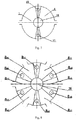
- Figure 8 shows the left end cover structure of a six-stage wave rotor refrigerator.
- first high pressure inlet chamber of six stages a 10 first low temperature outlet chamber of six stages a 11
- second high pressure inlet chamber of six stages a 20 second low temperature outlet chamber of six stages a 21
- third high pressure inlet chamber of six stages a 30 third high pressure inlet chamber of six stages a 30
- third low temperature outlet chamber of six stages a 31 fourth high pressure inlet chamber of six stages a 40
- fourth low temperature outlet chamber of six stages a 41 fifth high pressure inlet chamber of six stages a 50 , fifth low temperature outlet chamber of six stages a 51
- sixth high pressure inlet chamber of six stages a 60 sixth low temperature outlet chamber of six stages a 61 .
- the structure of the right end cover of the six-stage wave rotor refrigerator is similar to that of the left end cover.
- the working process of the six-stage refrigerator is similar to that of the two-stage refrigerator.
- Figure 9 shows the left end cover structure of an eight-stage wave rotor refrigerator.
- first high pressure inlet chamber of eight stages b 10 first low temperature outlet chamber of eight stages b 11 , second high pressure inlet chamber of eight stages b 20 , second low temperature outlet chamber of eight stages b 21 , third high pressure inlet chamber of eight stages b 30 , third low temperature outlet chamber of eight stages b 31 , fourth high pressure inlet chamber of eight stages b 40 , fourth low temperature outlet chamber b 41 , fifth high pressure inlet chamber of eight stages b 50 , fifth low temperature outlet chamber of eight stages b 51 , sixth high pressure inlet chamber of eight stages b 60 , sixth low temperature outlet chamber of eight stages b 61 , seventh high pressure inlet chamber of eight stages b 70 , seventh low temperature outlet chamber of eight stages b 71 , eighth high pressure inlet chamber of eight stages b 80 , eighth low temperature outlet chamber of eight stages b 81 .
- the structure of the right end cover of the eight-stage wave rotor refrigerator is similar to that of the left end cover.
- the working process of the eight-stage refrigerator is similar to that of the two-stage refrigerator.
Landscapes
- Engineering & Computer Science (AREA)
- Physics & Mathematics (AREA)
- Mechanical Engineering (AREA)
- Thermal Sciences (AREA)
- General Engineering & Computer Science (AREA)
- Structures Of Non-Positive Displacement Pumps (AREA)
- Compressors, Vaccum Pumps And Other Relevant Systems (AREA)
- Applications Or Details Of Rotary Compressors (AREA)
Abstract
Description
- The invention relates to a multistage wave rotor refrigeration machine which belongs to the technical field of gas expansion refrigeration.
- The gas wave refrigeration technology rose since the 1980s. The gas wave expansion refrigeration machine uses unsteady flow of the gas in the oscillation tube to separate the heat and cold.
- At present, the gas wave refrigeration technology is mainly used in the liquefaction and separation of mixed gas, light hydrocarbon recovery of liquefied petroleum gas, liquefaction of natural gas, generation of low temperature air source and other fields. The gas wave refrigerator has the advantages of easy operation, easy maintenance and high reliability compared with the ordinary turbo expander. The natural gas treatment process often needs depressurization, cooling and dehydration treatment.When the required pressure drop is large, the ordinary single-stage gas wave refrigerator is difficult to meet the operating conditions. Therefore, it is necessary to invent a multistage gas wave refrigerator to meet the demand of refrigeration under the condition of large pressure ratio.
- Most of the gas wave refrigerators belong to the single stage unsteady expansion refrigeration system(such as the Chinese patent
87101903.5 ,89213744.4 ,90222999.0 and so on). The expansion ratio is generally ranges from 2 to 4. If larger cooling temperature drop is needed, the isentropic refrigeration efficiency will decrease considerably. Therefore, it is necessary to invent a multistage refrigerator to meet the demand of refrigeration under the condition of large pressure ratio. There is only one type of multistage gas wave refrigerator (the Chinese patent96115022.X ) until now, which employs single opening oscillation tube. Although multistage refrigeration can be realized under large pressure ratio in the gas wave refrigerator of single opening oscillation tubes, the phenomenon of liquid accumulation may make the oscillation tube ruptured in the process of operating. And large bulk of the machine and slow heat dissipation in the working process are also disadvantages. - If several gas wave refrigerators are connected in series to realize refrigeration, expansion ratio of each machine could be decreased a lot. However, the pressure energy of the gas can't be effectively recovered and the series connection of refrigerators leads to large investment and the occupation. And the overall efficiency will reduce when the match between different stages of refrigerators is not good. Therefore, the invention of a refrigerator that can achieve efficient refrigeration at high pressure ratio, recover the pressure energy effectively and avoid the generation of liquid during the operation becomes a key issue of current gas wave refrigeration technology.
- The invention provides a kind of multistage wave rotor refrigerator to overcome the existing technology problems. About the structure of the machine, there are 30-280 oscillation tubes parallel to the axis in the circumferential direction of the wave rotor, which can realize 2-8 times unsteady expansion in the wave rotor to achieve gas cooling under a large pressure ratio.In this way, the expansion work produced by the expansion of the high pressure gas is recovered in the form of pressure energy to improve refrigeration efficiency. The oscillation tube with the form of double opening can effectively control the trend of liquid motion to avoid the liquid accumulation problems.
- The technical scheme of the present invention is that: a multistage wave rotor refrigerator includes a casing, a left end cover, a right end cover, a wave rotor, a central shaft, a high pressure inlet nozzle, a medium pressure outlet nozzle and a drive mechanism. The wave rotor is fixed to the circular disk of the central shaft by bolts. The wave rotor is placed in the casing whose left side is set with a left end cover and a right side a right end cover. Between the left end cover and the left side of central shaft there are two bearings behave as support. Another two bearings behave as support between the right end cover and the right side of central shaft. Oscillation tubes with constant cross-section are set in the wave rotor in circumferential direction. On the left end cover there are first high pressure inlet chamber of 2-8 stages, second low temperature outlet chamber of 2-8 stages, second high pressure inlet chamber of 2-8 stages and first low temperature outlet chamber of 2-8 stages in order. On the right end cover (25) there are second medium pressure outlet chamber of 2-8 stages, first low pressure inlet chamber of 2-8 stages, first medium pressure outlet chamber of 2-8 stages and second low pressure inlet chamber of 2-8 stages in order. The high pressure inlet nozzles of 2-8 stages are fixed on the left end cover by bolts, and the medium pressure outlet nozzles of 2-8 stages on the right end cover. The circumferential central line of high pressure inlet nozzles and medium pressure outlet nozzles is the same as the circumferential central line of end faces of oscillation tubes. The clearance fitting between stationary nozzles surface plane and rotary wave rotor surface plane needs to be controlled. The drive mechanism is an electromotor that drives the wave rotor on the central shaft to rotate in the casing through a coupling.
- There are 2-8 high-pressure inlet nozzles in the refrigerator, which could help realize unsteady expansion of gas 2-8 times.
- In the wave rotor of refrigerator there are 30-280 oscillation tubes.
- The beneficial effects of the present invention include that it simplifies the structure of machine and it is conducive to be installed and adjusted. The wave rotor of refrigerator of double opening oscillation tubes is mainly composed of a casing, a left end cover, a right end cover, a wave rotor, a central shaft, a high pressure inlet nozzle, a medium pressure outlet nozzle and a drive mechanism. The wave rotor and the central shaft are combined into a whole and rotate synchronously.
- The gas wave rotor refrigerator can reduce the temperature and pressure of the gas after 2-8 times expansion, which realizes 2-8 stages gas refrigeration. At the same time expansion ratio ranging from 4 to 20 could be realized that makes the machine more suitable for gas refrigeration under large pressure ratio.
- The refrigerator can transmit the expansion work generated by the expansion of high pressure gas to the low pressure gas expanded by itself in the oscillation tube through the shock wave, which raises the pressure level of the gas. The gas whose pressure rises could be expanded again in the device.The expansion work is recovered in the form of pressure energy, which greatly reduces the overall cooling pressure loss of the system and improves the refrigeration efficiency of the system.
- According to the present invention, the high temperature gas exhausted from the medium pressure chamber of the gas wave refrigerator could be cooled by external cooler, which effectively improves the heat dissipation efficiency.
- The gas wave refrigerator uses double opening oscillation tubes. When the moisture content of the gas is high, the gas would be condensed during the cooling process in oscillation tubes. Then the condensed liquid can discharge through both sides of oscillation tubes. So the refrigerator can work with liquid.
-
-
Figure 1 shows the working procedure of a two-stage wave rotor refrigerator. -
Figure 2 shows the structure of a two-stage wave rotor refrigerator. -
Figure 3 shows the structure of left end cover of a two-stage wave rotor refrigerator. -
Figure 4 shows the structure of right end cover of a two-stage wave rotor refrigerator. -
Figure 5 is the A-A section view inFigure 2 . -
Figure 6 is the B-B section view inFigure 2 . -
Figure 7 is the structure schematic diagram of the left end cover structure of a two-stage wave rotor refrigerator. -
Figure 8 is the structure schematic diagram of the left end cover structure of a six-stage wave rotor refrigerator. -
Figure 9 is the structure schematic diagram of the left end cover structure of an eight-stage wave rotor refrigerator. - In the
Figures: 1 .first high pressure inlet nozzle of two stages, 2.first low temperature outlet chamber of two stages, 3. second high pressure inlet nozzle of two stages, 4. second low temperature outlet chamber of two stages, 5.wave rotor, 6.oscillation tube, 7.second low pressure inlet chamber of two stages, 8.throttle valve, 9.first stage cooler, 10.first medium pressure outlet nozzle of two stages, 11.first low pressure inlet chamber of two stages, 12.second medium pressure outlet nozzle of two stages,13.second stage cooler, 14.first stage heat exchanger, 15.second high pressure inlet chamber of two stages, 16.left bearing end cover, 17.bearings, 18. first high pressure inlet chamber of two stages, 19.left end cover, 20.casing, 21.second medium pressure outlet chamber of two stages, 22.electromotor, 23.coupling, 24.right bearing end cover, 25.right end cover, 26.first medium pressure outlet chamber of two stages, 27.bolts, 28.central shaft, 28a.circular disk, a10.first high pressure inlet chamber of six stages, a11.first low temperature outlet chamber of six stages, a20.second high pressure inlet chamber of six stages, a21. second low temperature outlet chamber of six stages, a30.third high pressure inlet chamber of six stages, a31.third low temperature outlet chamber of six stages, a40.fourth high pressure inlet chamber of six stages, a41.fourth low temperature outlet chamber of six stages, a50.fifth high pressure inlet chamber of six stages, a51.fifth low temperature outlet chamber of six stages, a60.sixth high pressure inlet chamber of six stages,a61.sixth low temperature outlet chamber of six stages, b10.first high pressure inlet chamber of eight stages, bu.first low temperature outlet chamber of eight stages, b20.second high pressure inlet chamber of eight stages, b21.second low temperature outlet chamber of eight stages, b30.third high pressure inlet chamber of eight stages, b31.third low temperature outlet chamber of eight stages, b40.fourth high pressure inlet chamber of eight stages, b41. fourth low temperature outlet chamber of eight stages, b50.fifth high pressure inlet chamber of eight stages, b51.fifth low temperature outlet chamber of eight stages, b60.sixth high pressure inlet chamber of eight stages, b61.sixth low temperature outlet chamber of eight stages, b70.seventh high pressure inlet chamber of eight stages, b71.seventh low temperature outlet chamber of eight stages, b80.eighth high pressure inlet chamber of eight stages, b81.eighth low temperature outlet chamber of eight stages. - The two-stage refrigerator is introduced particularly according to the figures and the detailed description:
Figures 2 ,3 ,4 ,5 and 6 show the structure of a two-stage wave rotor refrigerator. In the figures, a multistage wave rotor refrigerator includes acasing 20, aleft end cover 19, aright end cover 25, a wave rotor 5, acentral shaft 28, high pressure inlet nozzles, medium pressure outlet nozzles and a drive mechanism. The wave rotor 5 is fixed to thecircular disk 28a of thecentral shaft 28 bybolts 27. The wave rotor 5 is composed of 30-280 oscillation tubes 6 of equal section. On theleft end cover 19 there are first high pressure inlet chamber of twostages 18, second low temperature outlet chamber of two stages 4, second high pressure inlet chamber of twostages 15 and first low temperature outlet chamber of twostages 2 in order. On theright end cover 25 there are second medium pressure outlet chamber of twostages 21, first low pressure inlet chamber of twostages 11, first medium pressure outlet chamber of twostages 26 and second low pressure inlet chamber of twostages 7 in order. The first high pressure inlet nozzle of two stages 1 and the second high pressure inlet nozzle of twostages 3 are respectively fixed to theleft end cover 19 by bolts. The first medium pressure outlet nozzle of twostages 10 and the second medium pressure outlet nozzle of twostages 12 are respectively fixed to theright end cover 25 by bolts. The circumferential central line of nozzles above is the same as the circumferential central line of end faces of oscillation tubes 6. The drive mechanism is an electromotor 22 that drives the wave rotor 5 on the central shaft 28to rotate in thecasing 20 through acoupling 23. The clearance fitting between stationary nozzles surface plane and rotary wave rotor 5 surface plane needs to be controlled. -
Figure 1 shows the working procedure of a two-stage wave rotor refrigerator. While working, the electromotor 22 drives the wave rotor 5 to rotate through thecentral shaft 28 then the high pressure gas enters the first high pressure inlet chamber of two stages 18.After that the gas enters the left side of oscillation tubes 6 via the first high pressure inlet nozzle of two stages 1. The injected high pressure gas transmits the expansion work in the form of shock wave to the low pressure gas in the oscillation tubes 6, so that temperature and pressure of the gas in the oscillation tubes 6 rises. So that the pressure level of the gas rises.Then the gas is discharged by the second medium pressure outlet nozzle of twostages 12. At last, after cooled by second stage cooler 13, the gas enters the firststage heat exchanger 14 to exchange the cold with the gas whose temperature is reduced after being expanded. - The temperature of medium pressure gas decreases after the gas exchanging the cold then the gas gets injected into the oscillation tubes 6 by second high pressure inlet nozzle of two
stages 3 to get expanded a second time making the temperature of gas lower. Motivated by pressure drop, the gas is exhausted out of the system via second low temperature outlet chamber of two stages 4 of which the position is confirmed by calculating matching of nozzles. After heat exchanging, another flux of gas flows back to the oscillation tubes 6 via first low pressure inlet chamber of two stages 11.At this time the high pressure gas from the second high pressure inlet nozzle of two stages 3gets expanded and transmits the expansion work in the form of shock wave to the gas in the oscillation tubes 6.The temperature and pressure of the gas in the oscillation tubes 6 rise and then the gas becomes medium pressure gas which then flows into first medium pressure outlet chamber of twostages 26 via first medium pressure outlet nozzle of twostages 10 and get exhausted out of oscillation tubes 6. The pressure and temperature of medium pressure gas decreases after flowing via throttle valve 8 and first stage cooler 9. Then the gas flows back to oscillation tubes 6 via second low pressure inlet chamber of twostages 7. After one period rotating of wave rotor 5, oscillation tubes 6 get connected with first high pressure inlet nozzle of two stages 1 one more time and low pressure gas prepares for attaining pressure energy next time. -
Figure 7 shows the left end cover structure of a two-stage wave rotor refrigerator. The first high pressure inlet chamber of twostages 18 and the second high pressure inlet chamber of twostages 15 are symmetrically set on the left end cover. Second low temperature outlet chamber of two stages 4 and first low temperature outlet chamber of twostages 2 are symmetrically set on the left end cover where high pressure inlet chambers and low temperature outlet chambers are cross-distributed. -
Figure 8 shows the left end cover structure of a six-stage wave rotor refrigerator. There are first high pressure inlet chamber of six stages a10, first low temperature outlet chamber of six stages a11, second high pressure inlet chamber of six stages a20, second low temperature outlet chamber of six stages a21, third high pressure inlet chamber of six stages a30, third low temperature outlet chamber of six stages a31, fourth high pressure inlet chamber of six stages a40, fourth low temperature outlet chamber of six stages a41, fifth high pressure inlet chamber of six stages a50, fifth low temperature outlet chamber of six stages a51, sixth high pressure inlet chamber of six stages a60, sixth low temperature outlet chamber of six stages a61. They were symmetrically located on the left end cover where the high pressure inlet chambers and the low temperature outlet chambers are cross-distributed. The structure of the right end cover of the six-stage wave rotor refrigerator is similar to that of the left end cover. The working process of the six-stage refrigerator is similar to that of the two-stage refrigerator. -
Figure 9 shows the left end cover structure of an eight-stage wave rotor refrigerator. There are first high pressure inlet chamber of eight stages b10, first low temperature outlet chamber of eight stages b11, second high pressure inlet chamber of eight stages b20, second low temperature outlet chamber of eight stages b21, third high pressure inlet chamber of eight stages b30, third low temperature outlet chamber of eight stages b31, fourth high pressure inlet chamber of eight stages b40, fourth low temperature outlet chamber b41, fifth high pressure inlet chamber of eight stages b50, fifth low temperature outlet chamber of eight stages b51, sixth high pressure inlet chamber of eight stages b60, sixth low temperature outlet chamber of eight stages b61, seventh high pressure inlet chamber of eight stages b70, seventh low temperature outlet chamber of eight stages b71, eighth high pressure inlet chamber of eight stages b80, eighth low temperature outlet chamber of eight stages b81. They were symmetrically located in the left end cover where the high pressure inlet chambers and the low temperature outlet chambers are cross-distributed. The structure of the right end cover of the eight-stage wave rotor refrigerator is similar to that of the left end cover. The working process of the eight-stage refrigerator is similar to that of the two-stage refrigerator.
Claims (4)
- A multistage wave rotor refrigerator including a casing (20), a left end cover (19) and a right end cover (25); the characteristics of the refrigerator include a wave rotor (5), a central shaft (28), high pressure inlet nozzles, medium pressure outlet nozzles and a drive mechanism; the wave rotor (5) is fixed on the circular disk (28a) of central shaft (28) through bolts (27); the wave rotor (5) is placed in the casing (20) whose left side is set with the left end cover (19) and right side the right end cover (25); between the left end cover (19) and the left side of central shaft (28) there are two bearings (17) behave as support; another two bearings (17) behave as support between the right end cover (25) and the right side of central shaft (28); oscillation tubes (6) with constant cross-section are set in the wave rotor (5) in circumferential direction; On the left end cover (19) there are first high pressure inlet chamber of 2-8 stages, second low temperature outlet chamber of 2-8 stages, second high pressure inlet chamber of 2-8 stages and first low temperature outlet chamber of 2-8 stages in order; on the right end cover (25) there are second medium pressure outlet chamber of 2-8 stages, first low pressure inlet chamber of 2-8 stages, medium pressure outlet chamber of 2-8 stages and second low pressure inlet chamber of 2-8 stages in order; the high pressure inlet nozzles of 2-8 stages are fixed on the left end cover (19) by bolts, and the medium pressure outlet nozzles of 2-8 stages on the right end cover (25); the circumferential central line of high pressure inlet nozzles and medium pressure outlet nozzles is the same as the circumferential central line of end faces of oscillation tubes (6); the clearance fitting between stationary nozzles surface plane and rotary wave rotor (5) surface plane needs to be controlled; The drive mechanism is an electromotor (22) that drives the wave rotor (5) on the central shaft (28) to rotate in the casing (20) through a coupling (23).
- The multistage wave rotor refrigerator according to the claim 1, the characteristics include that as for two-stage wave rotor refrigerator, on the left end cover (19) there are a first high pressure inlet chamber of two stages(18), a second low temperature outlet chamber of two stages (4), a second high pressure inlet chamber of two stages (15), a first low temperature outlet chamber of two stages (2) in order; on the right end cover (25) there are a second medium pressure outlet chamber of two stages (21), a first low pressure inlet chamber of two stages (11), a first medium pressure outlet chamber of two stages (26) and a second low pressure inlet chamber of two stages (7) in order; the first high pressure inlet nozzle of two stages (1) and the second high pressure inlet nozzle of two stages (3) are respectively fixed on the left end cover (19) by bolts; the first medium pressure outlet nozzle of two stages (10) and the second medium pressure outlet nozzle of two stages (12) are respectively fixed on the right end cover (25) by bolts(27).
- The multistage wave rotor refrigerator according to the claim 1, the characteristics include that the wave rotor refrigerator has 2-8 high pressure inlet nozzles which can realize 2-8 times unsteady expansion of gas in the refrigerator.
- The multistage wave rotor refrigerator according to the claim 1, the characteristics include that in the wave rotor (5) refrigerator there are 30-280 oscillation tubes (6).
Applications Claiming Priority (2)
| Application Number | Priority Date | Filing Date | Title |
|---|---|---|---|
| CN201710766787.6A CN107367084B (en) | 2017-08-31 | 2017-08-31 | A wave rotor type multistage refrigerator |
| PCT/CN2018/085286 WO2019041869A1 (en) | 2017-08-31 | 2018-05-02 | Wave rotor-based multi-stage refrigerator |
Publications (2)
| Publication Number | Publication Date |
|---|---|
| EP3489595A1 true EP3489595A1 (en) | 2019-05-29 |
| EP3489595A4 EP3489595A4 (en) | 2019-10-30 |
Family
ID=60312142
Family Applications (1)
| Application Number | Title | Priority Date | Filing Date |
|---|---|---|---|
| EP18845398.9A Ceased EP3489595A4 (en) | 2017-08-31 | 2018-05-02 | MULTI-STAGE REFRIGERATOR BASED ON WAVE ROTOR |
Country Status (4)
| Country | Link |
|---|---|
| US (1) | US20200191445A1 (en) |
| EP (1) | EP3489595A4 (en) |
| CN (1) | CN107367084B (en) |
| WO (1) | WO2019041869A1 (en) |
Cited By (4)
| Publication number | Priority date | Publication date | Assignee | Title |
|---|---|---|---|---|
| US11397030B2 (en) | 2020-07-10 | 2022-07-26 | Energy Recovery, Inc. | Low energy consumption refrigeration system with a rotary pressure exchanger replacing the bulk flow compressor and the high pressure expansion valve |
| US11421918B2 (en) | 2020-07-10 | 2022-08-23 | Energy Recovery, Inc. | Refrigeration system with high speed rotary pressure exchanger |
| US12085324B2 (en) | 2021-06-09 | 2024-09-10 | Energy Recovery, Inc. | Refrigeration and heat pump systems with pressure exchangers |
| US12209778B2 (en) | 2021-06-09 | 2025-01-28 | Energy Recovery, Inc. | Refrigeration and heat pump systems with pressure exchangers |
Families Citing this family (5)
| Publication number | Priority date | Publication date | Assignee | Title |
|---|---|---|---|---|
| CN107367084B (en) * | 2017-08-31 | 2019-07-30 | 大连理工大学 | A wave rotor type multistage refrigerator |
| CN114427756B (en) * | 2020-09-28 | 2024-02-23 | 中国石油化工股份有限公司 | A wave rotor and rotary heat separator |
| CN113669309B (en) * | 2021-08-11 | 2022-12-20 | 大连理工大学 | Condensation separation type air wave supercharging device and method |
| CN113702432B (en) * | 2021-08-30 | 2022-05-17 | 中国科学院力学研究所 | Test device for refrigerating by utilizing gas pressure energy and control method |
| CN114111081A (en) * | 2021-12-26 | 2022-03-01 | 大连理工大学 | Curved channel thermal-insulation type gas wave refrigerator |
Family Cites Families (6)
| Publication number | Priority date | Publication date | Assignee | Title |
|---|---|---|---|---|
| CN1010709B (en) | 1987-03-17 | 1990-12-05 | 华北石油管理局勘察设计院 | Turbulence expansion engine |
| US5412950A (en) * | 1993-07-27 | 1995-05-09 | Hu; Zhimin | Energy recovery system |
| CN1085824C (en) * | 1996-01-12 | 2002-05-29 | 大连理工大学 | Multi-stage gas wave refrigerator |
| CN100575816C (en) * | 2008-04-30 | 2009-12-30 | 大连理工大学 | Dissipative gas wave refrigerator with outer circulation |
| CN107367084B (en) * | 2017-08-31 | 2019-07-30 | 大连理工大学 | A wave rotor type multistage refrigerator |
| CN207247611U (en) * | 2017-08-31 | 2018-04-17 | 大连理工大学 | A wave rotor multi-stage refrigerator |
-
2017
- 2017-08-31 CN CN201710766787.6A patent/CN107367084B/en active Active
-
2018
- 2018-05-02 WO PCT/CN2018/085286 patent/WO2019041869A1/en not_active Ceased
- 2018-05-02 US US16/315,962 patent/US20200191445A1/en not_active Abandoned
- 2018-05-02 EP EP18845398.9A patent/EP3489595A4/en not_active Ceased
Cited By (11)
| Publication number | Priority date | Publication date | Assignee | Title |
|---|---|---|---|---|
| US11397030B2 (en) | 2020-07-10 | 2022-07-26 | Energy Recovery, Inc. | Low energy consumption refrigeration system with a rotary pressure exchanger replacing the bulk flow compressor and the high pressure expansion valve |
| US11421918B2 (en) | 2020-07-10 | 2022-08-23 | Energy Recovery, Inc. | Refrigeration system with high speed rotary pressure exchanger |
| US11982481B2 (en) | 2020-07-10 | 2024-05-14 | Energy Recovery, Inc. | Refrigeration system with high speed rotary pressure exchanger |
| DK181605B1 (en) * | 2020-07-10 | 2024-06-20 | Energy Recovery Inc | LOW ENERGY CONSUMPTION COOLING SYSTEM WITH A ROTARY PRESSURE EXCHANGER THAT REPLACES THE MAIN FLOW COMPRESSOR AND THE HIGH PRESSURE EXPANSION VALVE |
| US12181195B2 (en) | 2020-07-10 | 2024-12-31 | Energy Recovery | Low energy consumption refrigeration system with a rotary pressure exchanger replacing the bulk flow compressor and the high pressure expansion system |
| US12276447B2 (en) | 2020-07-10 | 2025-04-15 | Energy Recovery, Inc. | Refrigeration system with high speed rotary pressure exchanger |
| DK182146B1 (en) * | 2020-07-10 | 2025-09-09 | Energy Recovery Inc | COOLING SYSTEM WITH FAST-ROTATING PRESSURE EXCHANGERS |
| US12085324B2 (en) | 2021-06-09 | 2024-09-10 | Energy Recovery, Inc. | Refrigeration and heat pump systems with pressure exchangers |
| US12209778B2 (en) | 2021-06-09 | 2025-01-28 | Energy Recovery, Inc. | Refrigeration and heat pump systems with pressure exchangers |
| US12392528B2 (en) | 2021-06-09 | 2025-08-19 | Energy Recovery, Inc. | Control of refrigeration and heat pump systems that include pressure exchangers |
| US12590738B2 (en) | 2021-06-09 | 2026-03-31 | Energy Recovery, Inc. | Heat pump systems with pressure exchangers |
Also Published As
| Publication number | Publication date |
|---|---|
| EP3489595A4 (en) | 2019-10-30 |
| CN107367084A (en) | 2017-11-21 |
| US20200191445A1 (en) | 2020-06-18 |
| WO2019041869A1 (en) | 2019-03-07 |
| CN107367084B (en) | 2019-07-30 |
Similar Documents
| Publication | Publication Date | Title |
|---|---|---|
| EP3489595A1 (en) | Wave rotor-based multi-stage refrigerator | |
| CN1090744C (en) | Two phase flow turbine | |
| US20220333830A1 (en) | Refrigeration device and method | |
| CA2671914A1 (en) | A jet pump system for heat and cold management, apparatus, arrangement and methods of use | |
| BRPI0924263A2 (en) | improvements in multistage centrifugal compressors | |
| JP6585830B2 (en) | Wave rotor type automatic cascade refrigeration system and operation method thereof | |
| CN110986408A (en) | Integrated neon refrigerator and refrigeration method | |
| Wang et al. | Thermodynamic investigation of a centrifugal reverse Brayton cycle for refrigeration in air conditioning filed | |
| CN1193200C (en) | Rotor compression-expander for refrigeration system | |
| CN111594280B (en) | Dual-turbine gas suspension ORC power generation system and control method | |
| CN207247611U (en) | A wave rotor multi-stage refrigerator | |
| CN212959283U (en) | A closed loop coupling device | |
| CN116045405A (en) | A parallel high-power heat pump refrigeration unit and its parallel connection method | |
| CN107367083B (en) | A triple supply magnetic levitation chiller | |
| CN206803547U (en) | A double-opening variable cross-section gas wave refrigerator | |
| CN206369370U (en) | Oblique flow pressuring expansion refrigerating plant again | |
| CN211261360U (en) | Compressor system and air conditioning unit | |
| CN210089170U (en) | Cold source system based on magnetic suspension unit | |
| CN106595114A (en) | Oblique flow re-pressurizing expansion refrigeration device and method | |
| US12455113B2 (en) | Device and method for refrigerating or liquefying a fluid | |
| CN204268753U (en) | The system of refrigerating gas compressor or compound compressor inlet gas | |
| CN215446941U (en) | Overlapping unit | |
| CN113701385B (en) | Supersonic refrigeration system driven by thermoacoustic compressor | |
| CN112032112A (en) | Closed cycle coupling device and using method thereof | |
| CN207751194U (en) | A kind of water-cooling screw rod formula handpiece Water Chilling Units |
Legal Events
| Date | Code | Title | Description |
|---|---|---|---|
| STAA | Information on the status of an ep patent application or granted ep patent |
Free format text: STATUS: UNKNOWN |
|
| STAA | Information on the status of an ep patent application or granted ep patent |
Free format text: STATUS: THE INTERNATIONAL PUBLICATION HAS BEEN MADE |
|
| PUAI | Public reference made under article 153(3) epc to a published international application that has entered the european phase |
Free format text: ORIGINAL CODE: 0009012 |
|
| STAA | Information on the status of an ep patent application or granted ep patent |
Free format text: STATUS: REQUEST FOR EXAMINATION WAS MADE |
|
| 17P | Request for examination filed |
Effective date: 20190220 |
|
| AK | Designated contracting states |
Kind code of ref document: A1 Designated state(s): AL AT BE BG CH CY CZ DE DK EE ES FI FR GB GR HR HU IE IS IT LI LT LU LV MC MK MT NL NO PL PT RO RS SE SI SK SM TR |
|
| AX | Request for extension of the european patent |
Extension state: BA ME |
|
| A4 | Supplementary search report drawn up and despatched |
Effective date: 20190926 |
|
| RIC1 | Information provided on ipc code assigned before grant |
Ipc: F25B 1/10 20060101ALI20190920BHEP Ipc: F25B 9/06 20060101ALI20190920BHEP Ipc: F25B 9/10 20060101AFI20190920BHEP Ipc: F25B 41/04 20060101ALI20190920BHEP |
|
| STAA | Information on the status of an ep patent application or granted ep patent |
Free format text: STATUS: EXAMINATION IS IN PROGRESS |
|
| 17Q | First examination report despatched |
Effective date: 20200619 |
|
| DAV | Request for validation of the european patent (deleted) | ||
| DAX | Request for extension of the european patent (deleted) | ||
| REG | Reference to a national code |
Ref country code: DE Ref legal event code: R003 |
|
| STAA | Information on the status of an ep patent application or granted ep patent |
Free format text: STATUS: THE APPLICATION HAS BEEN REFUSED |
|
| 18R | Application refused |
Effective date: 20210823 |