EP3489519A1 - Fan motor and vehicle comprising same - Google Patents
Fan motor and vehicle comprising same Download PDFInfo
- Publication number
- EP3489519A1 EP3489519A1 EP17831343.3A EP17831343A EP3489519A1 EP 3489519 A1 EP3489519 A1 EP 3489519A1 EP 17831343 A EP17831343 A EP 17831343A EP 3489519 A1 EP3489519 A1 EP 3489519A1
- Authority
- EP
- European Patent Office
- Prior art keywords
- magnet
- fan motor
- rotating shaft
- stator
- disposed
- Prior art date
- Legal status (The legal status is an assumption and is not a legal conclusion. Google has not performed a legal analysis and makes no representation as to the accuracy of the status listed.)
- Granted
Links
Images


Classifications
-
- F—MECHANICAL ENGINEERING; LIGHTING; HEATING; WEAPONS; BLASTING
- F04—POSITIVE - DISPLACEMENT MACHINES FOR LIQUIDS; PUMPS FOR LIQUIDS OR ELASTIC FLUIDS
- F04D—NON-POSITIVE-DISPLACEMENT PUMPS
- F04D25/00—Pumping installations or systems
- F04D25/02—Units comprising pumps and their driving means
- F04D25/06—Units comprising pumps and their driving means the pump being electrically driven
- F04D25/0606—Units comprising pumps and their driving means the pump being electrically driven the electric motor being specially adapted for integration in the pump
- F04D25/0613—Units comprising pumps and their driving means the pump being electrically driven the electric motor being specially adapted for integration in the pump the electric motor being of the inside-out type, i.e. the rotor is arranged radially outside a central stator
- F04D25/0633—Details of the magnetic circuit
-
- F—MECHANICAL ENGINEERING; LIGHTING; HEATING; WEAPONS; BLASTING
- F04—POSITIVE - DISPLACEMENT MACHINES FOR LIQUIDS; PUMPS FOR LIQUIDS OR ELASTIC FLUIDS
- F04D—NON-POSITIVE-DISPLACEMENT PUMPS
- F04D25/00—Pumping installations or systems
- F04D25/02—Units comprising pumps and their driving means
- F04D25/06—Units comprising pumps and their driving means the pump being electrically driven
- F04D25/0606—Units comprising pumps and their driving means the pump being electrically driven the electric motor being specially adapted for integration in the pump
-
- F—MECHANICAL ENGINEERING; LIGHTING; HEATING; WEAPONS; BLASTING
- F04—POSITIVE - DISPLACEMENT MACHINES FOR LIQUIDS; PUMPS FOR LIQUIDS OR ELASTIC FLUIDS
- F04D—NON-POSITIVE-DISPLACEMENT PUMPS
- F04D25/00—Pumping installations or systems
- F04D25/02—Units comprising pumps and their driving means
- F04D25/06—Units comprising pumps and their driving means the pump being electrically driven
- F04D25/0606—Units comprising pumps and their driving means the pump being electrically driven the electric motor being specially adapted for integration in the pump
- F04D25/0613—Units comprising pumps and their driving means the pump being electrically driven the electric motor being specially adapted for integration in the pump the electric motor being of the inside-out type, i.e. the rotor is arranged radially outside a central stator
-
- F—MECHANICAL ENGINEERING; LIGHTING; HEATING; WEAPONS; BLASTING
- F04—POSITIVE - DISPLACEMENT MACHINES FOR LIQUIDS; PUMPS FOR LIQUIDS OR ELASTIC FLUIDS
- F04D—NON-POSITIVE-DISPLACEMENT PUMPS
- F04D25/00—Pumping installations or systems
- F04D25/02—Units comprising pumps and their driving means
- F04D25/06—Units comprising pumps and their driving means the pump being electrically driven
- F04D25/0606—Units comprising pumps and their driving means the pump being electrically driven the electric motor being specially adapted for integration in the pump
- F04D25/0613—Units comprising pumps and their driving means the pump being electrically driven the electric motor being specially adapted for integration in the pump the electric motor being of the inside-out type, i.e. the rotor is arranged radially outside a central stator
- F04D25/064—Details of the rotor
-
- H—ELECTRICITY
- H02—GENERATION; CONVERSION OR DISTRIBUTION OF ELECTRIC POWER
- H02K—DYNAMO-ELECTRIC MACHINES
- H02K1/00—Details of the magnetic circuit
- H02K1/06—Details of the magnetic circuit characterised by the shape, form or construction
- H02K1/12—Stationary parts of the magnetic circuit
- H02K1/14—Stator cores with salient poles
- H02K1/145—Stator cores with salient poles having an annular coil, e.g. of the claw-pole type
-
- H—ELECTRICITY
- H02—GENERATION; CONVERSION OR DISTRIBUTION OF ELECTRIC POWER
- H02K—DYNAMO-ELECTRIC MACHINES
- H02K1/00—Details of the magnetic circuit
- H02K1/06—Details of the magnetic circuit characterised by the shape, form or construction
- H02K1/22—Rotating parts of the magnetic circuit
- H02K1/27—Rotor cores with permanent magnets
- H02K1/2786—Outer rotors
-
- H—ELECTRICITY
- H02—GENERATION; CONVERSION OR DISTRIBUTION OF ELECTRIC POWER
- H02K—DYNAMO-ELECTRIC MACHINES
- H02K1/00—Details of the magnetic circuit
- H02K1/06—Details of the magnetic circuit characterised by the shape, form or construction
- H02K1/22—Rotating parts of the magnetic circuit
- H02K1/27—Rotor cores with permanent magnets
- H02K1/2786—Outer rotors
- H02K1/2787—Outer rotors the magnetisation axis of the magnets being perpendicular to the rotor axis
- H02K1/2789—Outer rotors the magnetisation axis of the magnets being perpendicular to the rotor axis the rotor consisting of two or more circumferentially positioned magnets
- H02K1/2791—Surface mounted magnets; Inset magnets
-
- H—ELECTRICITY
- H02—GENERATION; CONVERSION OR DISTRIBUTION OF ELECTRIC POWER
- H02K—DYNAMO-ELECTRIC MACHINES
- H02K3/00—Details of windings
- H02K3/46—Fastening of windings on the stator or rotor structure
- H02K3/47—Air-gap windings, i.e. iron-free windings
-
- H—ELECTRICITY
- H02—GENERATION; CONVERSION OR DISTRIBUTION OF ELECTRIC POWER
- H02K—DYNAMO-ELECTRIC MACHINES
- H02K5/00—Casings; Enclosures; Supports
- H02K5/04—Casings or enclosures characterised by the shape, form or construction thereof
- H02K5/10—Casings or enclosures characterised by the shape, form or construction thereof with arrangements for protection from ingress, e.g. water or fingers
-
- H—ELECTRICITY
- H02—GENERATION; CONVERSION OR DISTRIBUTION OF ELECTRIC POWER
- H02K—DYNAMO-ELECTRIC MACHINES
- H02K7/00—Arrangements for handling mechanical energy structurally associated with dynamo-electric machines, e.g. structural association with mechanical driving motors or auxiliary dynamo-electric machines
- H02K7/14—Structural association with mechanical loads, e.g. with hand-held machine tools or fans
-
- H—ELECTRICITY
- H02—GENERATION; CONVERSION OR DISTRIBUTION OF ELECTRIC POWER
- H02K—DYNAMO-ELECTRIC MACHINES
- H02K9/00—Arrangements for cooling or ventilating
- H02K9/02—Arrangements for cooling or ventilating by ambient air flowing through the machine
- H02K9/04—Arrangements for cooling or ventilating by ambient air flowing through the machine having means for generating a flow of cooling medium
- H02K9/06—Arrangements for cooling or ventilating by ambient air flowing through the machine having means for generating a flow of cooling medium with fans or impellers driven by the machine shaft
-
- F—MECHANICAL ENGINEERING; LIGHTING; HEATING; WEAPONS; BLASTING
- F04—POSITIVE - DISPLACEMENT MACHINES FOR LIQUIDS; PUMPS FOR LIQUIDS OR ELASTIC FLUIDS
- F04D—NON-POSITIVE-DISPLACEMENT PUMPS
- F04D25/00—Pumping installations or systems
- F04D25/02—Units comprising pumps and their driving means
- F04D25/08—Units comprising pumps and their driving means the working fluid being air, e.g. for ventilation
-
- F—MECHANICAL ENGINEERING; LIGHTING; HEATING; WEAPONS; BLASTING
- F05—INDEXING SCHEMES RELATING TO ENGINES OR PUMPS IN VARIOUS SUBCLASSES OF CLASSES F01-F04
- F05D—INDEXING SCHEME FOR ASPECTS RELATING TO NON-POSITIVE-DISPLACEMENT MACHINES OR ENGINES, GAS-TURBINES OR JET-PROPULSION PLANTS
- F05D2260/00—Function
- F05D2260/95—Preventing corrosion
-
- H—ELECTRICITY
- H02—GENERATION; CONVERSION OR DISTRIBUTION OF ELECTRIC POWER
- H02K—DYNAMO-ELECTRIC MACHINES
- H02K2205/00—Specific aspects not provided for in the other groups of this subclass relating to casings, enclosures, supports
- H02K2205/09—Machines characterised by drain passages or by venting, breathing or pressure compensating means
-
- H—ELECTRICITY
- H02—GENERATION; CONVERSION OR DISTRIBUTION OF ELECTRIC POWER
- H02K—DYNAMO-ELECTRIC MACHINES
- H02K2211/00—Specific aspects not provided for in the other groups of this subclass relating to measuring or protective devices or electric components
- H02K2211/03—Machines characterised by circuit boards, e.g. pcb
Definitions
- Embodiments relate to a fan motor and a vehicle including the same.
- a fan motor is an air blowing device in which a blade is coupled to a rotor to supply or discharge air.
- the fan motor includes the rotor, a stator, and the blade, and the rotor is installed outside the stator.
- a coil forming a rotating magnetic field may be wound around the stator and cause an electrical interaction with the rotor to induce rotation of the rotor.
- the blade coupled to the rotor rotates.
- a housing of the fan motor includes a rotor, a stator, and a fan disposed therein.
- a blowhole is implemented in the housing of the fan motor, and thus the housing is in an open state. Consequently, there is a problem in that moisture containing salt (hereinafter referred to as salt water) permeates through the housing and causes corrosion of the rotor or stator including a magnet.
- salt water moisture containing salt
- an object of the present invention is to provide a fan motor, which is capable of preventing introduction of salt water, and a vehicle including the same.
- a fan motor includes a rotating shaft, a stator including a hole in which the rotating shaft is disposed, a rotor disposed outside the stator, a fan coupled to the rotating shaft, and a housing in which the stator and the rotor are disposed, wherein the rotor includes a yoke and a first magnet coupled to the yoke, and the fan motor further includes a magnetic fluid disposed between the first magnet and the stator.
- the magnetic fluid may be applied on a lower end of the first magnet.
- the yoke may include a scattering preventer which extends by being bent from a lower end of the yoke toward the rotating shaft.
- An upper surface of the scattering preventer and a lower surface of the first magnet may come into surface contact.
- the housing may include a columnar portion protruding upward in a cylindrical shape from a lower surface of the housing and having an inner circumferential surface, and the columnar portion may be disposed between the rotating shaft and the stator.
- the fan may include a hub configured to be coupled to the rotating shaft and the rotor, the yoke of the rotor may be disposed between the hub and the stator, and the first magnet of the rotor may be disposed between the yoke and the stator.
- a fan motor includes a rotating shaft, a stator including a hole in which the rotating shaft is disposed, a rotor disposed outside the stator, a fan coupled to the rotating shaft, and a housing in which the stator and the rotor are disposed, wherein the rotor includes a yoke and a first magnet coupled to the yoke, a second magnet is disposed in at least one of the fan or the housing, and the fan motor further includes a magnetic fluid disposed on the second magnet.
- the second magnet may be coupled to the fan so that a portion of a surface of the second magnet is exposed to the outside.
- the housing may include a bottom surface facing a lower end of the fan motor, and the second magnet may be coupled to a lower end of the fan so that the exposed surface of the second magnet faces the bottom surface of the housing.
- the housing may include a bottom surface facing a lower end of the fan motor, and the second magnet may be coupled to the bottom surface of the housing so that a portion of a surface of the second magnet is exposed to the outside.
- the housing may further include a scattering preventer protruding from the bottom surface toward the rotating shaft.
- the scattering preventer may be disposed between the outside of the fan and the second magnet with respect to the center of the rotating shaft.
- the scattering preventer may protrude upward from the bottom surface of the housing in a circumferential direction with respect to the center of the rotating shaft.
- the second magnet may be disposed within a radius of the fan with the rotating shaft as the center.
- the magnetic fluid may partially overlap with the rotating shaft in a direction of the rotating shaft.
- a vehicle includes a fan motor including a rotating shaft, a stator including a hole in which the rotating shaft is disposed, a rotor disposed outside the stator, a fan coupled to the rotating shaft, and a housing in which the stator and the rotor are disposed, wherein the rotor includes a yoke and a first magnet coupled to the yoke, and the fan motor further includes a magnetic fluid disposed between the first magnet and the stator.
- a magnetic fluid being filled in a gap between a stator and a magnet of a rotor and thus keeping the inside of a motor airtight, there is an advantageous effect in that introduction of salt water or foreign substances into the motor is prevented.
- a magnetic fluid being filled in a gap between a lower end of a fan and a bottom surface of a housing and thus keeping the inside of a motor airtight, there is an advantageous effect in that introduction of salt water or foreign substances into the motor is prevented.
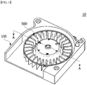
- FIG. 1 is a view illustrating a fan motor according to an embodiment
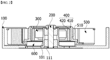
- FIG. 2 is a cross-sectional view of the fan motor taken along line A-A of FIG. 1 .
- a fan motor 10 may include a housing 100, a rotating shaft 200, a stator 300, a rotor 400, and a fan 500.
- a blowhole configured to discharge suctioned air and a flow path corresponding thereto may be provided in the housing 100.
- the housing 100 may include a columnar portion 101.
- the columnar portion 101 may be formed to vertically protrude from a bottom surface of the housing 100.
- the columnar portion 101 may be formed to be hollow.
- a bearing 111 may be installed inside the columnar portion 101.
- the rotating shaft 200 is fitted to the bearing 111 and rotatably disposed inside the columnar portion 101.
- the rotating shaft 200 is connected to the rotor 400. Also, an upper end of the rotating shaft 200 may be connected to the fan 500.
- the stator 300 may be fitted and coupled to the columnar portion 101.
- the stator 300 causes an electrical interaction with the rotor 400 and induces rotation of the rotor 400.
- a coil may be wound around the stator 300.
- a specific configuration of the stator for winding a coil is as follows.
- the stator 300 may include a stator core including plurality of teeth.
- the stator core may have an annular yoke and teeth facing outward from the yoke.
- the teeth may be provided at predetermined intervals along a circumference of the yoke.
- the stator core may be formed by stacking a plurality of plates in the form of a thin steel plate on one another.
- the rotor 400 is disposed outside the stator 300.
- the rotor 400 may include a yoke 410 and a first magnet 420.
- the yoke 410 is coupled to the inside of a hub 510 of the fan 500.
- the first magnet 420 may be attached to an inner circumferential surface of a side portion of the yoke 410.
- the hub 510 of the fan 500 is coupled to the rotating shaft 200. As the rotating shaft 200 rotates, the fan 500 rotates and blows air.
- a printed circuit board 600 may be disposed below the fan 500 and coupled to the housing 100.
- FIG. 3 is a view illustrating a fan motor according to a first modified example
- FIG. 4 is a view illustrating a magnetic fluid placed in a gap between a stator and a magnet of a rotor in the fan motor of FIG. 3 .
- Magnetic fluid 700 may be applied on a first magnet 420 of a rotor 400.
- Magnetic fluid refers to a fluid produced by stabilizing and dispersing magnetic powder in a colloidal shape in a liquid and then adding a surfactant to prevent precipitation or condensation.
- the magnetic fluid 700 may be applied on a lower end of the first magnet 420. This is to effectively block introduction of salt water because a gap between the lower end of the first magnet 420 and a stator 300 may become an inlet through which sat water is introduced.
- the gap between the stator 300 and the first magnet 420 is very small, when the magnetic fluid 700 is applied on a surface of the first magnet 420, the magnetic fluid 700 fills the gap between the lower end of the first magnet 420 and the stator 300 and thus blocks introduction of salt water or foreign substances into the fan motor.
- a yoke 410 may include a scattering preventer 411.
- the scattering preventer 411 may be formed to extend by being bent inward from a lower end of the yoke 410.
- Such a scattering preventer 411 serves to physically prevent scattering of the magnetic fluid 700, which is placed in the gap between the stator 300 and the lower end of the first magnet 420, to the outside of the yoke 410 due to rotation of the rotor 400.
- FIG. 5 is a view illustrating a fan motor according to a second modified example
- FIG. 6 is a view illustrating a magnetic fluid placed in a gap between the bottom of a housing and a magnet of a fan in the fan motor of FIG. 5 .
- a separate second magnet 800 may be installed at a lower end of a wing of a fan 500.
- the second magnet 800 may be installed at the wing of the fan 500 so that a portion 810 of a surface of the second magnet 800 is exposed.
- the exposed portion 810 of the surface of the second magnet 800 faces a bottom surface 110 of a housing 100.
- the second magnet 800 may be integrally formed with the fan 500 by insert molding.
- the second magnet 800 may be installed at every wing of the fan 500.
- a magnetic fluid 700 is applied on the exposed portion 810 of the surface of the second magnet 800. Because a gap between the bottom surface 110 of the housing 100 and the second magnet 800 is very small, when the magnetic fluid 700 is applied on the surface of the second magnet 800, the magnetic fluid 700 fills the gap between the second magnet 800 and the bottom surface 110 of the housing 100 and thus blocks introduction of salt water or foreign substances into the fan motor.
- the housing 100 may include a scattering preventer 120.
- the scattering preventer 120 protrudes from the bottom surface 110 of the housing 100 and is placed between the second magnet 800 and an outer boundary of the fan 500 with respect to a radial direction.
- Such a scattering preventer 120 may be formed in a circumferential direction about a rotating shaft 200 (see FIG. 5 ).
- Such a scattering preventer 120 physically prevents scattering of the magnetic fluid 700, which is placed in the gap between the second magnet 800 and the bottom surface 110 of the housing 100, to the outside of the fan 500 due to rotation of the rotor 400.
- FIG. 7 is a view illustrating a fan motor according to a third modified example
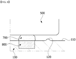
- FIG. 8 is a view illustrating a magnetic fluid placed in a gap between a magnet of a housing and a lower end of a fan in the fan motor of FIG. 7 .
- a separate second magnet 800 may be installed at a bottom surface 110 of a housing 100.
- the second magnet 800 may be installed at the bottom surface 110 of the housing 100 so that a portion 810 of a surface of the second magnet 800 is exposed.
- the exposed portion 810 of the surface of the second magnet 800 faces a lower end of a fan 500.
- the second magnet 800 may be integrally formed with the housing 100 by insert molding.
- the second magnet 800 may be formed in a circumferential direction about a rotating shaft 200 (see FIG. 7 ). Also, the second magnet 800 is disposed within a radius of the fan 500 in a radial direction about the rotating shaft 200 (see FIG. 7 ).
- a magnetic fluid 700 is applied on the exposed portion 810 of the surface of the second magnet 800. Because a gap between the bottom surface 110 of the housing 100 and the second magnet 800 is very small, when the magnetic fluid 700 is applied on the surface of the second magnet 800, the magnetic fluid 700 fills the gap between the second magnet 800 and the lower end of the fan 500 and thus blocks introduction of salt water or foreign substances into the fan motor.
- the housing 100 may include a scattering preventer 120.
- the scattering preventer 120 protrudes from the bottom surface 110 of the housing 100 and is placed between the second magnet 800 and an outer boundary of the fan 500 with respect to a radial direction.
- Such a scattering preventer 120 may be formed in a circumferential direction about a rotating shaft 200 (see FIG. 7 ).
- Such a scattering preventer 120 physically prevents scattering of the magnetic fluid 700, which is placed in the gap between the second magnet 800 and the lower end of the fan 500, to the outside of the fan 500 due to rotation of the rotor 400.
Landscapes
- Engineering & Computer Science (AREA)
- Power Engineering (AREA)
- Mechanical Engineering (AREA)
- General Engineering & Computer Science (AREA)
- Connection Of Motors, Electrical Generators, Mechanical Devices, And The Like (AREA)
- Motor Or Generator Frames (AREA)
- Structures Of Non-Positive Displacement Pumps (AREA)
Abstract
Description
- Embodiments relate to a fan motor and a vehicle including the same.
- A fan motor is an air blowing device in which a blade is coupled to a rotor to supply or discharge air. The fan motor includes the rotor, a stator, and the blade, and the rotor is installed outside the stator. Also, a coil forming a rotating magnetic field may be wound around the stator and cause an electrical interaction with the rotor to induce rotation of the rotor. When the rotor rotates, the blade coupled to the rotor rotates.
- A housing of the fan motor includes a rotor, a stator, and a fan disposed therein. However, a blowhole is implemented in the housing of the fan motor, and thus the housing is in an open state. Consequently, there is a problem in that moisture containing salt (hereinafter referred to as salt water) permeates through the housing and causes corrosion of the rotor or stator including a magnet.
- Accordingly, embodiments are for solving the above-described problem, and an object of the present invention is to provide a fan motor, which is capable of preventing introduction of salt water, and a vehicle including the same.
- Objects of the present invention are not limited to that mentioned above, and other objects not mentioned herein should be clearly understood by those of ordinary skill in the art from the description below.
- To achieve the above object, a fan motor according to an embodiment includes a rotating shaft, a stator including a hole in which the rotating shaft is disposed, a rotor disposed outside the stator, a fan coupled to the rotating shaft, and a housing in which the stator and the rotor are disposed, wherein the rotor includes a yoke and a first magnet coupled to the yoke, and the fan motor further includes a magnetic fluid disposed between the first magnet and the stator.
- The magnetic fluid may be applied on a lower end of the first magnet.
- The yoke may include a scattering preventer which extends by being bent from a lower end of the yoke toward the rotating shaft.
- An upper surface of the scattering preventer and a lower surface of the first magnet may come into surface contact.
- The housing may include a columnar portion protruding upward in a cylindrical shape from a lower surface of the housing and having an inner circumferential surface, and the columnar portion may be disposed between the rotating shaft and the stator.
- The fan may include a hub configured to be coupled to the rotating shaft and the rotor, the yoke of the rotor may be disposed between the hub and the stator, and the first magnet of the rotor may be disposed between the yoke and the stator.
- To achieve the above object, a fan motor according to another embodiment includes a rotating shaft, a stator including a hole in which the rotating shaft is disposed, a rotor disposed outside the stator, a fan coupled to the rotating shaft, and a housing in which the stator and the rotor are disposed, wherein the rotor includes a yoke and a first magnet coupled to the yoke, a second magnet is disposed in at least one of the fan or the housing, and the fan motor further includes a magnetic fluid disposed on the second magnet.
- The second magnet may be coupled to the fan so that a portion of a surface of the second magnet is exposed to the outside.
- The housing may include a bottom surface facing a lower end of the fan motor, and the second magnet may be coupled to a lower end of the fan so that the exposed surface of the second magnet faces the bottom surface of the housing.
- The housing may include a bottom surface facing a lower end of the fan motor, and the second magnet may be coupled to the bottom surface of the housing so that a portion of a surface of the second magnet is exposed to the outside.
- The housing may further include a scattering preventer protruding from the bottom surface toward the rotating shaft.
- The scattering preventer may be disposed between the outside of the fan and the second magnet with respect to the center of the rotating shaft.
- The scattering preventer may protrude upward from the bottom surface of the housing in a circumferential direction with respect to the center of the rotating shaft.
- The second magnet may be disposed within a radius of the fan with the rotating shaft as the center.
- The magnetic fluid may partially overlap with the rotating shaft in a direction of the rotating shaft.
- To achieve the above object, a vehicle according to an embodiment includes a fan motor including a rotating shaft, a stator including a hole in which the rotating shaft is disposed, a rotor disposed outside the stator, a fan coupled to the rotating shaft, and a housing in which the stator and the rotor are disposed, wherein the rotor includes a yoke and a first magnet coupled to the yoke, and the fan motor further includes a magnetic fluid disposed between the first magnet and the stator.
- According to embodiments, by a magnetic fluid being filled in a gap between a stator and a magnet of a rotor and thus keeping the inside of a motor airtight, there is an advantageous effect in that introduction of salt water or foreign substances into the motor is prevented.
- According to embodiments, by a magnetic fluid being filled in a gap between a lower end of a fan and a bottom surface of a housing and thus keeping the inside of a motor airtight, there is an advantageous effect in that introduction of salt water or foreign substances into the motor is prevented.
-
-
FIG. 1 is a view illustrating a fan motor according to an embodiment. -
FIG. 2 is a cross-sectional view of the fan motor taken along line A-A ofFIG. 1 . -
FIG. 3 is a view illustrating a fan motor according to a first modified example. -
FIG. 4 is a view illustrating a magnetic fluid placed in a gap between a stator and a magnet of a rotor in the fan motor ofFIG. 3 . -
FIG. 5 is a view illustrating a fan motor according to a second modified example. -
FIG. 6 is a view illustrating a magnetic fluid placed in a gap between the bottom of a housing and a magnet of a fan in the fan motor ofFIG. 5 . -
FIG. 7 is a view illustrating a fan motor according to a third modified example. -
FIG. 8 is a view illustrating a magnetic fluid placed in a gap between a magnet of a housing and a lower end of a fan in the fan motor ofFIG. 7 . - Hereinafter, exemplary embodiments of the present invention will be described in detail with reference to the accompanying drawings. Objects, specific advantages, and novel features of the present invention will become more apparent from the detailed description and exemplary embodiments below related to the accompanying drawings. Also, the terms or words used in the present specification and the claims should not be limitedly interpreted in their general or dictionary meanings but, based on the principle that an inventor may properly define concepts of terms to describe his or her invention in the best possible way, should be interpreted in meanings and concepts in accordance with the technical idea of the present invention. In addition, in describing the present invention, detailed description of a known related art that may unnecessarily obscure the gist of the present invention will be omitted.
-
FIG. 1 is a view illustrating a fan motor according to an embodiment, andFIG. 2 is a cross-sectional view of the fan motor taken along line A-A ofFIG. 1 . - Referring to
FIGS. 1 and2 , afan motor 10 according to an embodiment may include ahousing 100, a rotatingshaft 200, astator 300, arotor 400, and afan 500. - A blowhole configured to discharge suctioned air and a flow path corresponding thereto may be provided in the
housing 100. Also, thehousing 100 may include acolumnar portion 101. Thecolumnar portion 101 may be formed to vertically protrude from a bottom surface of thehousing 100. Also, thecolumnar portion 101 may be formed to be hollow. - A
bearing 111 may be installed inside thecolumnar portion 101. - The rotating
shaft 200 is fitted to thebearing 111 and rotatably disposed inside thecolumnar portion 101. The rotatingshaft 200 is connected to therotor 400. Also, an upper end of the rotatingshaft 200 may be connected to thefan 500. - The
stator 300 may be fitted and coupled to thecolumnar portion 101. Thestator 300 causes an electrical interaction with therotor 400 and induces rotation of therotor 400. To cause the electrical interaction with therotor 400, a coil may be wound around thestator 300. A specific configuration of the stator for winding a coil is as follows. - The
stator 300 may include a stator core including plurality of teeth. The stator core may have an annular yoke and teeth facing outward from the yoke. The teeth may be provided at predetermined intervals along a circumference of the yoke. Meanwhile, the stator core may be formed by stacking a plurality of plates in the form of a thin steel plate on one another. - The
rotor 400 is disposed outside thestator 300. Therotor 400 may include ayoke 410 and afirst magnet 420. Theyoke 410 is coupled to the inside of ahub 510 of thefan 500. Thefirst magnet 420 may be attached to an inner circumferential surface of a side portion of theyoke 410. - The
hub 510 of thefan 500 is coupled to therotating shaft 200. As therotating shaft 200 rotates, thefan 500 rotates and blows air. - A printed
circuit board 600 may be disposed below thefan 500 and coupled to thehousing 100. -
FIG. 3 is a view illustrating a fan motor according to a first modified example, andFIG. 4 is a view illustrating a magnetic fluid placed in a gap between a stator and a magnet of a rotor in the fan motor ofFIG. 3 . - Referring to
FIGS. 3 and4 , amagnetic fluid 700 may be applied on afirst magnet 420 of arotor 400. Magnetic fluid refers to a fluid produced by stabilizing and dispersing magnetic powder in a colloidal shape in a liquid and then adding a surfactant to prevent precipitation or condensation. - The
magnetic fluid 700 may be applied on a lower end of thefirst magnet 420. This is to effectively block introduction of salt water because a gap between the lower end of thefirst magnet 420 and astator 300 may become an inlet through which sat water is introduced. - Because the gap between the
stator 300 and thefirst magnet 420 is very small, when themagnetic fluid 700 is applied on a surface of thefirst magnet 420, themagnetic fluid 700 fills the gap between the lower end of thefirst magnet 420 and thestator 300 and thus blocks introduction of salt water or foreign substances into the fan motor. - Referring to
FIG. 4 , ayoke 410 may include ascattering preventer 411. Thescattering preventer 411 may be formed to extend by being bent inward from a lower end of theyoke 410. Such ascattering preventer 411 serves to physically prevent scattering of themagnetic fluid 700, which is placed in the gap between thestator 300 and the lower end of thefirst magnet 420, to the outside of theyoke 410 due to rotation of therotor 400. -
FIG. 5 is a view illustrating a fan motor according to a second modified example, andFIG. 6 is a view illustrating a magnetic fluid placed in a gap between the bottom of a housing and a magnet of a fan in the fan motor ofFIG. 5 . - Referring to
FIGS. 5 and6 , a separatesecond magnet 800 may be installed at a lower end of a wing of afan 500. In this case, thesecond magnet 800 may be installed at the wing of thefan 500 so that aportion 810 of a surface of thesecond magnet 800 is exposed. The exposedportion 810 of the surface of thesecond magnet 800 faces abottom surface 110 of ahousing 100. Thesecond magnet 800 may be integrally formed with thefan 500 by insert molding. Thesecond magnet 800 may be installed at every wing of thefan 500. - A
magnetic fluid 700 is applied on the exposedportion 810 of the surface of thesecond magnet 800. Because a gap between thebottom surface 110 of thehousing 100 and thesecond magnet 800 is very small, when themagnetic fluid 700 is applied on the surface of thesecond magnet 800, themagnetic fluid 700 fills the gap between thesecond magnet 800 and thebottom surface 110 of thehousing 100 and thus blocks introduction of salt water or foreign substances into the fan motor. - Referring to
FIG. 6 , thehousing 100 may include ascattering preventer 120. Thescattering preventer 120 protrudes from thebottom surface 110 of thehousing 100 and is placed between thesecond magnet 800 and an outer boundary of thefan 500 with respect to a radial direction. Such ascattering preventer 120 may be formed in a circumferential direction about a rotating shaft 200 (seeFIG. 5 ). - Such a
scattering preventer 120 physically prevents scattering of themagnetic fluid 700, which is placed in the gap between thesecond magnet 800 and thebottom surface 110 of thehousing 100, to the outside of thefan 500 due to rotation of therotor 400. -
FIG. 7 is a view illustrating a fan motor according to a third modified example, andFIG. 8 is a view illustrating a magnetic fluid placed in a gap between a magnet of a housing and a lower end of a fan in the fan motor ofFIG. 7 . - Referring to
FIGS. 7 and8 , a separatesecond magnet 800 may be installed at abottom surface 110 of ahousing 100. In this case, thesecond magnet 800 may be installed at thebottom surface 110 of thehousing 100 so that aportion 810 of a surface of thesecond magnet 800 is exposed. The exposedportion 810 of the surface of thesecond magnet 800 faces a lower end of afan 500. Thesecond magnet 800 may be integrally formed with thehousing 100 by insert molding. Thesecond magnet 800 may be formed in a circumferential direction about a rotating shaft 200 (seeFIG. 7 ). Also, thesecond magnet 800 is disposed within a radius of thefan 500 in a radial direction about the rotating shaft 200 (seeFIG. 7 ). - A
magnetic fluid 700 is applied on the exposedportion 810 of the surface of thesecond magnet 800. Because a gap between thebottom surface 110 of thehousing 100 and thesecond magnet 800 is very small, when themagnetic fluid 700 is applied on the surface of thesecond magnet 800, themagnetic fluid 700 fills the gap between thesecond magnet 800 and the lower end of thefan 500 and thus blocks introduction of salt water or foreign substances into the fan motor. - Referring to
FIG. 8 , thehousing 100 may include ascattering preventer 120. Thescattering preventer 120 protrudes from thebottom surface 110 of thehousing 100 and is placed between thesecond magnet 800 and an outer boundary of thefan 500 with respect to a radial direction. Such ascattering preventer 120 may be formed in a circumferential direction about a rotating shaft 200 (seeFIG. 7 ). - Such a
scattering preventer 120 physically prevents scattering of themagnetic fluid 700, which is placed in the gap between thesecond magnet 800 and the lower end of thefan 500, to the outside of thefan 500 due to rotation of therotor 400. - The fan motor and vehicle including the same according to one exemplary embodiment of the present invention have been described in detail above with reference to the accompanying drawings.
- The above description is merely illustrative of the technical idea of the present invention. Those of ordinary skill in the art to which the present invention pertains should be able to make various modifications, changes, and substitutions within the scope not departing from essential characteristics of the present invention. Therefore, the embodiments disclosed herein and the accompanying drawings are for describing, instead of limiting, the technical idea of the present invention, and the scope of the technical idea of the present invention is not limited by the embodiments and the accompanying drawings. The scope of the present invention should be interpreted on the basis of the claims below, and all technical ideas within the equivalent scope should be interpreted as belonging to the scope of the present invention.
- 10: fan motor, 100: housing, 101: columnar portion, 110: bottom surface, 120, 411: scattering preventer, 200: rotating shaft, 300: stator, 400: rotor, 410: yoke, 420: first magnet, 500: fan, 600: printed circuit board, 700: magnetic fluid, 800: second magnet
Claims (16)
- A fan motor comprising:a rotating shaft;a stator including a hole in which the rotating shaft is disposed;a rotor disposed outside the stator;a fan coupled to the rotating shaft; anda housing in which the stator and the rotor are disposed,wherein the rotor includes a yoke and a first magnet coupled to the yoke,the fan motor further comprising a magnetic fluid disposed between the first magnet and the stator.
- The fan motor of claim 1, wherein the magnetic fluid is applied on a lower end of the first magnet.
- The fan motor of claim 2, wherein the yoke includes a scattering preventer which extends by being bent from a lower end of the yoke toward the rotating shaft.
- The fan motor of claim 3, wherein an upper surface of the scattering preventer and a lower surface of the first magnet come into surface contact.
- The fan motor of claim 1, wherein:the housing includes a columnar portion protruding upward in a cylindrical shape from a lower surface of the housing and having an inner circumferential surface; andthe columnar portion is disposed between the rotating shaft and the stator.
- The fan motor of claim 5, wherein:the fan includes a hub configured to be coupled to the rotating shaft and the rotor;the yoke of the rotor is disposed between the hub and the stator; andthe first magnet of the rotor is disposed between the yoke and the stator.
- A fan motor comprising:a rotating shaft;a stator including a hole in which the rotating shaft is disposed;a rotor disposed outside the stator;a fan coupled to the rotating shaft; anda housing in which the stator and the rotor are disposed, wherein:the rotor includes a yoke and a first magnet coupled to the yoke; anda second magnet is disposed in at least one of the fan or the housing,the fan motor further comprising a magnetic fluid disposed on the second magnet.
- The fan motor of claim 7, wherein the second magnet is coupled to the fan so that a portion of a surface of the second magnet is exposed to the outside.
- The fan motor of claim 8, wherein:the housing includes a bottom surface facing a lower end of the fan motor; andthe second magnet is coupled to a lower end of the fan so that the exposed surface of the second magnet faces the bottom surface of the housing.
- The fan motor of claim 7, wherein:the housing includes a bottom surface facing a lower end of the fan motor; andthe second magnet is coupled to the bottom surface of the housing so that a portion of a surface of the second magnet is exposed to the outside.
- The fan motor of claim 8 or 10, wherein the housing further includes a scattering preventer protruding from the bottom surface toward the rotating shaft.
- The fan motor of claim 11, wherein the scattering preventer is disposed between the outside of the fan and the second magnet with respect to the center of the rotating shaft.
- The fan motor of claim 11, wherein the scattering preventer protrudes upward from the bottom surface of the housing in a circumferential direction with respect to the center of the rotating shaft.
- The fan motor of claim 7, wherein the second magnet is disposed within a radius of the fan with the rotating shaft as the center.
- The fan motor of claim 14, wherein the magnetic fluid partially overlaps with the rotating shaft in a direction of the rotating shaft.
- A vehicle comprising a fan motor, the fan motor comprising:a rotating shaft;a stator including a hole in which the rotating shaft is disposed;a rotor disposed outside the stator;a fan coupled to the rotating shaft; anda housing in which the stator and the rotor are disposed,wherein the rotor includes a yoke and a first magnet coupled to the yoke,the fan motor further comprising a magnetic fluid disposed between the first magnet and the stator.
Applications Claiming Priority (2)
| Application Number | Priority Date | Filing Date | Title |
|---|---|---|---|
| KR1020160092828A KR102599972B1 (en) | 2016-07-21 | 2016-07-21 | Fan motor and vehicle having the same |
| PCT/KR2017/007762 WO2018016870A1 (en) | 2016-07-21 | 2017-07-19 | Fan motor and vehicle comprising same |
Publications (3)
| Publication Number | Publication Date |
|---|---|
| EP3489519A1 true EP3489519A1 (en) | 2019-05-29 |
| EP3489519A4 EP3489519A4 (en) | 2020-03-18 |
| EP3489519B1 EP3489519B1 (en) | 2022-05-25 |
Family
ID=60992397
Family Applications (1)
| Application Number | Title | Priority Date | Filing Date |
|---|---|---|---|
| EP17831343.3A Active EP3489519B1 (en) | 2016-07-21 | 2017-07-19 | Fan motor and vehicle comprising same |
Country Status (6)
| Country | Link |
|---|---|
| US (1) | US10897169B2 (en) |
| EP (1) | EP3489519B1 (en) |
| JP (1) | JP6982610B2 (en) |
| KR (1) | KR102599972B1 (en) |
| CN (1) | CN109477489B (en) |
| WO (1) | WO2018016870A1 (en) |
Families Citing this family (3)
| Publication number | Priority date | Publication date | Assignee | Title |
|---|---|---|---|---|
| AU2018408707A1 (en) | 2018-02-14 | 2020-08-06 | Techtronic Cordless Gp | Outer rotor motor |
| KR102087523B1 (en) | 2018-12-24 | 2020-03-10 | 뉴모텍(주) | Fan motor |
| KR102693819B1 (en) * | 2021-12-06 | 2024-08-12 | 가천대학교 산학협력단 | Sleeve for motor rotor |
Family Cites Families (18)
| Publication number | Priority date | Publication date | Assignee | Title |
|---|---|---|---|---|
| JPS61476U (en) * | 1984-06-01 | 1986-01-06 | 日本電気精器株式会社 | Spindle motor for magnetic disk |
| GB2363434B (en) | 1999-01-22 | 2002-10-23 | Seagate Technology Llc | Ferrofluidic seal between a shaft and a hub for a disk hard drive |
| JP2004023927A (en) * | 2002-06-18 | 2004-01-22 | Adda Corp | Blower using magnetic fluid |
| CN2636491Y (en) | 2003-07-04 | 2004-08-25 | 深圳市贝来电气有限公司 | Internal cooled type electric machine |
| KR100611006B1 (en) * | 2004-11-08 | 2006-08-10 | 엘지이노텍 주식회사 | Spindle motor with axial sealing structure |
| US20060119198A1 (en) | 2004-12-03 | 2006-06-08 | Chuy-Nan Chio | Shaftless magnetic trajectory fan |
| JP4531584B2 (en) | 2005-02-17 | 2010-08-25 | Ntn株式会社 | Fluid dynamic bearing device and motor provided with the same |
| US20090134719A1 (en) * | 2006-04-14 | 2009-05-28 | Ciiis, Llc | Electric motor containing ferromagnetic particles |
| TWI349409B (en) * | 2006-08-14 | 2011-09-21 | Delta Electronics Inc | Fan, motor and magnetic conducting housing thereof |
| CN201714985U (en) | 2010-05-18 | 2011-01-19 | 张安戈 | Magnetorheological fluid sealing device of elevator magnetorheological fluid brake |
| JP5748155B2 (en) | 2010-12-23 | 2015-07-15 | イーグル工業株式会社 | Sealing device using magnetic fluid |
| JP2013017337A (en) * | 2011-07-05 | 2013-01-24 | Nippon Densan Corp | Motor and method for manufacturing motor |
| JP6260481B2 (en) | 2013-10-21 | 2018-01-17 | 株式会社デンソー | Centrifugal blower |
| JP2015081520A (en) * | 2013-10-21 | 2015-04-27 | 株式会社デンソー | Centrifugal blower |
| JP2015089234A (en) | 2013-10-30 | 2015-05-07 | 日本電産株式会社 | Fan motor |
| TWI577931B (en) * | 2015-05-28 | 2017-04-11 | 建準電機工業股份有限公司 | Motor of ceiling fan with illuminating module |
| JP6309921B2 (en) * | 2015-07-31 | 2018-04-11 | ミネベアミツミ株式会社 | How to correct rotor imbalance |
| DE102018207916A1 (en) * | 2017-05-22 | 2018-11-22 | Nidec Corporation | Stator unit, motor and fan motor |
-
2016
- 2016-07-21 KR KR1020160092828A patent/KR102599972B1/en active Active
-
2017
- 2017-07-19 EP EP17831343.3A patent/EP3489519B1/en active Active
- 2017-07-19 US US16/319,244 patent/US10897169B2/en active Active
- 2017-07-19 WO PCT/KR2017/007762 patent/WO2018016870A1/en not_active Ceased
- 2017-07-19 JP JP2019503297A patent/JP6982610B2/en active Active
- 2017-07-19 CN CN201780045175.6A patent/CN109477489B/en active Active
Also Published As
| Publication number | Publication date |
|---|---|
| JP2019523625A (en) | 2019-08-22 |
| WO2018016870A1 (en) | 2018-01-25 |
| CN109477489A (en) | 2019-03-15 |
| CN109477489B (en) | 2021-07-30 |
| EP3489519B1 (en) | 2022-05-25 |
| EP3489519A4 (en) | 2020-03-18 |
| US20200244122A1 (en) | 2020-07-30 |
| KR20180010552A (en) | 2018-01-31 |
| US10897169B2 (en) | 2021-01-19 |
| JP6982610B2 (en) | 2021-12-17 |
| KR102599972B1 (en) | 2023-11-09 |
Similar Documents
| Publication | Publication Date | Title |
|---|---|---|
| US9033680B2 (en) | Electric fan | |
| EP2886871B1 (en) | Waterproof axial flow fan | |
| US10897169B2 (en) | Fan motor and vehicle comprising same | |
| US20190181701A1 (en) | Motor for drone and drone comprising same | |
| EP2793370B1 (en) | Fan motor | |
| KR101493635B1 (en) | Fan motor | |
| US20190052138A1 (en) | Rotor assembly and motor including the same | |
| KR101840492B1 (en) | Motor for drain pump and drain pump using the same | |
| US20190195230A1 (en) | Centrifugal fan | |
| US11300137B2 (en) | Centrifugal fan | |
| US20190128280A1 (en) | Centrifugal fan | |
| JP2016167942A (en) | Brushless motor | |
| JP2016010279A (en) | Blower for vehicle | |
| JP6668313B2 (en) | Drain pump motor, method of manufacturing the same, and drain pump having the motor | |
| EP3490114B1 (en) | Fan motor and vehicle comprising same | |
| KR102087523B1 (en) | Fan motor | |
| EP3364527B1 (en) | Electric motor and blower | |
| JP2016167943A (en) | Brushless motor | |
| JP2015142437A (en) | Electric motor | |
| JP6372139B2 (en) | Rotating electric machine | |
| JP2009024649A (en) | Centrifugal fan with drip-proof structure | |
| JP6305205B2 (en) | Magnet rotor type motor and pump including the motor | |
| JP6373059B2 (en) | Magnet rotor type motor and pump including the motor | |
| JP2015220910A (en) | Magnet rotor type motor and pump including the motor | |
| KR20150135073A (en) | Stator assembly, magnet rotor type motor with stator assembly and pump |
Legal Events
| Date | Code | Title | Description |
|---|---|---|---|
| STAA | Information on the status of an ep patent application or granted ep patent |
Free format text: STATUS: THE INTERNATIONAL PUBLICATION HAS BEEN MADE |
|
| PUAI | Public reference made under article 153(3) epc to a published international application that has entered the european phase |
Free format text: ORIGINAL CODE: 0009012 |
|
| STAA | Information on the status of an ep patent application or granted ep patent |
Free format text: STATUS: REQUEST FOR EXAMINATION WAS MADE |
|
| 17P | Request for examination filed |
Effective date: 20190121 |
|
| AK | Designated contracting states |
Kind code of ref document: A1 Designated state(s): AL AT BE BG CH CY CZ DE DK EE ES FI FR GB GR HR HU IE IS IT LI LT LU LV MC MK MT NL NO PL PT RO RS SE SI SK SM TR |
|
| AX | Request for extension of the european patent |
Extension state: BA ME |
|
| DAV | Request for validation of the european patent (deleted) | ||
| DAX | Request for extension of the european patent (deleted) | ||
| A4 | Supplementary search report drawn up and despatched |
Effective date: 20200214 |
|
| RIC1 | Information provided on ipc code assigned before grant |
Ipc: H02K 3/47 20060101ALI20200210BHEP Ipc: F04D 25/06 20060101AFI20200210BHEP Ipc: F04D 29/40 20060101ALI20200210BHEP Ipc: H02K 7/14 20060101ALI20200210BHEP Ipc: H02K 5/10 20060101ALI20200210BHEP |
|
| GRAP | Despatch of communication of intention to grant a patent |
Free format text: ORIGINAL CODE: EPIDOSNIGR1 |
|
| STAA | Information on the status of an ep patent application or granted ep patent |
Free format text: STATUS: GRANT OF PATENT IS INTENDED |
|
| INTG | Intention to grant announced |
Effective date: 20211008 |
|
| GRAJ | Information related to disapproval of communication of intention to grant by the applicant or resumption of examination proceedings by the epo deleted |
Free format text: ORIGINAL CODE: EPIDOSDIGR1 |
|
| STAA | Information on the status of an ep patent application or granted ep patent |
Free format text: STATUS: REQUEST FOR EXAMINATION WAS MADE |
|
| GRAP | Despatch of communication of intention to grant a patent |
Free format text: ORIGINAL CODE: EPIDOSNIGR1 |
|
| STAA | Information on the status of an ep patent application or granted ep patent |
Free format text: STATUS: GRANT OF PATENT IS INTENDED |
|
| INTC | Intention to grant announced (deleted) | ||
| INTG | Intention to grant announced |
Effective date: 20220216 |
|
| GRAS | Grant fee paid |
Free format text: ORIGINAL CODE: EPIDOSNIGR3 |
|
| GRAA | (expected) grant |
Free format text: ORIGINAL CODE: 0009210 |
|
| STAA | Information on the status of an ep patent application or granted ep patent |
Free format text: STATUS: THE PATENT HAS BEEN GRANTED |
|
| AK | Designated contracting states |
Kind code of ref document: B1 Designated state(s): AL AT BE BG CH CY CZ DE DK EE ES FI FR GB GR HR HU IE IS IT LI LT LU LV MC MK MT NL NO PL PT RO RS SE SI SK SM TR |
|
| REG | Reference to a national code |
Ref country code: GB Ref legal event code: FG4D |
|
| REG | Reference to a national code |
Ref country code: CH Ref legal event code: EP |
|
| REG | Reference to a national code |
Ref country code: DE Ref legal event code: R096 Ref document number: 602017057865 Country of ref document: DE |
|
| REG | Reference to a national code |
Ref country code: AT Ref legal event code: REF Ref document number: 1494364 Country of ref document: AT Kind code of ref document: T Effective date: 20220615 |
|
| REG | Reference to a national code |
Ref country code: IE Ref legal event code: FG4D Ref country code: NL Ref legal event code: FP |
|
| REG | Reference to a national code |
Ref country code: LT Ref legal event code: MG9D |
|
| REG | Reference to a national code |
Ref country code: AT Ref legal event code: MK05 Ref document number: 1494364 Country of ref document: AT Kind code of ref document: T Effective date: 20220525 |
|
| PG25 | Lapsed in a contracting state [announced via postgrant information from national office to epo] |
Ref country code: SE Free format text: LAPSE BECAUSE OF FAILURE TO SUBMIT A TRANSLATION OF THE DESCRIPTION OR TO PAY THE FEE WITHIN THE PRESCRIBED TIME-LIMIT Effective date: 20220525 Ref country code: PT Free format text: LAPSE BECAUSE OF FAILURE TO SUBMIT A TRANSLATION OF THE DESCRIPTION OR TO PAY THE FEE WITHIN THE PRESCRIBED TIME-LIMIT Effective date: 20220926 Ref country code: NO Free format text: LAPSE BECAUSE OF FAILURE TO SUBMIT A TRANSLATION OF THE DESCRIPTION OR TO PAY THE FEE WITHIN THE PRESCRIBED TIME-LIMIT Effective date: 20220825 Ref country code: LT Free format text: LAPSE BECAUSE OF FAILURE TO SUBMIT A TRANSLATION OF THE DESCRIPTION OR TO PAY THE FEE WITHIN THE PRESCRIBED TIME-LIMIT Effective date: 20220525 Ref country code: HR Free format text: LAPSE BECAUSE OF FAILURE TO SUBMIT A TRANSLATION OF THE DESCRIPTION OR TO PAY THE FEE WITHIN THE PRESCRIBED TIME-LIMIT Effective date: 20220525 Ref country code: GR Free format text: LAPSE BECAUSE OF FAILURE TO SUBMIT A TRANSLATION OF THE DESCRIPTION OR TO PAY THE FEE WITHIN THE PRESCRIBED TIME-LIMIT Effective date: 20220826 Ref country code: FI Free format text: LAPSE BECAUSE OF FAILURE TO SUBMIT A TRANSLATION OF THE DESCRIPTION OR TO PAY THE FEE WITHIN THE PRESCRIBED TIME-LIMIT Effective date: 20220525 Ref country code: ES Free format text: LAPSE BECAUSE OF FAILURE TO SUBMIT A TRANSLATION OF THE DESCRIPTION OR TO PAY THE FEE WITHIN THE PRESCRIBED TIME-LIMIT Effective date: 20220525 Ref country code: BG Free format text: LAPSE BECAUSE OF FAILURE TO SUBMIT A TRANSLATION OF THE DESCRIPTION OR TO PAY THE FEE WITHIN THE PRESCRIBED TIME-LIMIT Effective date: 20220825 Ref country code: AT Free format text: LAPSE BECAUSE OF FAILURE TO SUBMIT A TRANSLATION OF THE DESCRIPTION OR TO PAY THE FEE WITHIN THE PRESCRIBED TIME-LIMIT Effective date: 20220525 |
|
| PG25 | Lapsed in a contracting state [announced via postgrant information from national office to epo] |
Ref country code: RS Free format text: LAPSE BECAUSE OF FAILURE TO SUBMIT A TRANSLATION OF THE DESCRIPTION OR TO PAY THE FEE WITHIN THE PRESCRIBED TIME-LIMIT Effective date: 20220525 Ref country code: PL Free format text: LAPSE BECAUSE OF FAILURE TO SUBMIT A TRANSLATION OF THE DESCRIPTION OR TO PAY THE FEE WITHIN THE PRESCRIBED TIME-LIMIT Effective date: 20220525 Ref country code: LV Free format text: LAPSE BECAUSE OF FAILURE TO SUBMIT A TRANSLATION OF THE DESCRIPTION OR TO PAY THE FEE WITHIN THE PRESCRIBED TIME-LIMIT Effective date: 20220525 Ref country code: IS Free format text: LAPSE BECAUSE OF FAILURE TO SUBMIT A TRANSLATION OF THE DESCRIPTION OR TO PAY THE FEE WITHIN THE PRESCRIBED TIME-LIMIT Effective date: 20220925 |
|
| PG25 | Lapsed in a contracting state [announced via postgrant information from national office to epo] |
Ref country code: SM Free format text: LAPSE BECAUSE OF FAILURE TO SUBMIT A TRANSLATION OF THE DESCRIPTION OR TO PAY THE FEE WITHIN THE PRESCRIBED TIME-LIMIT Effective date: 20220525 Ref country code: SK Free format text: LAPSE BECAUSE OF FAILURE TO SUBMIT A TRANSLATION OF THE DESCRIPTION OR TO PAY THE FEE WITHIN THE PRESCRIBED TIME-LIMIT Effective date: 20220525 Ref country code: RO Free format text: LAPSE BECAUSE OF FAILURE TO SUBMIT A TRANSLATION OF THE DESCRIPTION OR TO PAY THE FEE WITHIN THE PRESCRIBED TIME-LIMIT Effective date: 20220525 Ref country code: EE Free format text: LAPSE BECAUSE OF FAILURE TO SUBMIT A TRANSLATION OF THE DESCRIPTION OR TO PAY THE FEE WITHIN THE PRESCRIBED TIME-LIMIT Effective date: 20220525 Ref country code: DK Free format text: LAPSE BECAUSE OF FAILURE TO SUBMIT A TRANSLATION OF THE DESCRIPTION OR TO PAY THE FEE WITHIN THE PRESCRIBED TIME-LIMIT Effective date: 20220525 Ref country code: CZ Free format text: LAPSE BECAUSE OF FAILURE TO SUBMIT A TRANSLATION OF THE DESCRIPTION OR TO PAY THE FEE WITHIN THE PRESCRIBED TIME-LIMIT Effective date: 20220525 |
|
| PG25 | Lapsed in a contracting state [announced via postgrant information from national office to epo] |
Ref country code: MC Free format text: LAPSE BECAUSE OF FAILURE TO SUBMIT A TRANSLATION OF THE DESCRIPTION OR TO PAY THE FEE WITHIN THE PRESCRIBED TIME-LIMIT Effective date: 20220525 |
|
| REG | Reference to a national code |
Ref country code: DE Ref legal event code: R097 Ref document number: 602017057865 Country of ref document: DE Ref country code: CH Ref legal event code: PL |
|
| REG | Reference to a national code |
Ref country code: BE Ref legal event code: MM Effective date: 20220731 |
|
| PG25 | Lapsed in a contracting state [announced via postgrant information from national office to epo] |
Ref country code: AL Free format text: LAPSE BECAUSE OF FAILURE TO SUBMIT A TRANSLATION OF THE DESCRIPTION OR TO PAY THE FEE WITHIN THE PRESCRIBED TIME-LIMIT Effective date: 20220525 |
|
| PLBE | No opposition filed within time limit |
Free format text: ORIGINAL CODE: 0009261 |
|
| STAA | Information on the status of an ep patent application or granted ep patent |
Free format text: STATUS: NO OPPOSITION FILED WITHIN TIME LIMIT |
|
| GBPC | Gb: european patent ceased through non-payment of renewal fee |
Effective date: 20220825 |
|
| PG25 | Lapsed in a contracting state [announced via postgrant information from national office to epo] |
Ref country code: LU Free format text: LAPSE BECAUSE OF NON-PAYMENT OF DUE FEES Effective date: 20220719 Ref country code: LI Free format text: LAPSE BECAUSE OF NON-PAYMENT OF DUE FEES Effective date: 20220731 Ref country code: CH Free format text: LAPSE BECAUSE OF NON-PAYMENT OF DUE FEES Effective date: 20220731 |
|
| 26N | No opposition filed |
Effective date: 20230228 |
|
| PG25 | Lapsed in a contracting state [announced via postgrant information from national office to epo] |
Ref country code: SI Free format text: LAPSE BECAUSE OF FAILURE TO SUBMIT A TRANSLATION OF THE DESCRIPTION OR TO PAY THE FEE WITHIN THE PRESCRIBED TIME-LIMIT Effective date: 20220525 Ref country code: BE Free format text: LAPSE BECAUSE OF NON-PAYMENT OF DUE FEES Effective date: 20220731 |
|
| PG25 | Lapsed in a contracting state [announced via postgrant information from national office to epo] |
Ref country code: IE Free format text: LAPSE BECAUSE OF NON-PAYMENT OF DUE FEES Effective date: 20220719 |
|
| PG25 | Lapsed in a contracting state [announced via postgrant information from national office to epo] |
Ref country code: GB Free format text: LAPSE BECAUSE OF NON-PAYMENT OF DUE FEES Effective date: 20220825 |
|
| PG25 | Lapsed in a contracting state [announced via postgrant information from national office to epo] |
Ref country code: IT Free format text: LAPSE BECAUSE OF FAILURE TO SUBMIT A TRANSLATION OF THE DESCRIPTION OR TO PAY THE FEE WITHIN THE PRESCRIBED TIME-LIMIT Effective date: 20220525 |
|
| PG25 | Lapsed in a contracting state [announced via postgrant information from national office to epo] |
Ref country code: HU Free format text: LAPSE BECAUSE OF FAILURE TO SUBMIT A TRANSLATION OF THE DESCRIPTION OR TO PAY THE FEE WITHIN THE PRESCRIBED TIME-LIMIT; INVALID AB INITIO Effective date: 20170719 |
|
| PG25 | Lapsed in a contracting state [announced via postgrant information from national office to epo] |
Ref country code: MK Free format text: LAPSE BECAUSE OF FAILURE TO SUBMIT A TRANSLATION OF THE DESCRIPTION OR TO PAY THE FEE WITHIN THE PRESCRIBED TIME-LIMIT Effective date: 20220525 Ref country code: CY Free format text: LAPSE BECAUSE OF FAILURE TO SUBMIT A TRANSLATION OF THE DESCRIPTION OR TO PAY THE FEE WITHIN THE PRESCRIBED TIME-LIMIT Effective date: 20220525 |
|
| PG25 | Lapsed in a contracting state [announced via postgrant information from national office to epo] |
Ref country code: TR Free format text: LAPSE BECAUSE OF FAILURE TO SUBMIT A TRANSLATION OF THE DESCRIPTION OR TO PAY THE FEE WITHIN THE PRESCRIBED TIME-LIMIT Effective date: 20220525 |
|
| PG25 | Lapsed in a contracting state [announced via postgrant information from national office to epo] |
Ref country code: MT Free format text: LAPSE BECAUSE OF FAILURE TO SUBMIT A TRANSLATION OF THE DESCRIPTION OR TO PAY THE FEE WITHIN THE PRESCRIBED TIME-LIMIT Effective date: 20220525 |
|
| PG25 | Lapsed in a contracting state [announced via postgrant information from national office to epo] |
Ref country code: BG Free format text: LAPSE BECAUSE OF FAILURE TO SUBMIT A TRANSLATION OF THE DESCRIPTION OR TO PAY THE FEE WITHIN THE PRESCRIBED TIME-LIMIT Effective date: 20220525 |
|
| PG25 | Lapsed in a contracting state [announced via postgrant information from national office to epo] |
Ref country code: BG Free format text: LAPSE BECAUSE OF FAILURE TO SUBMIT A TRANSLATION OF THE DESCRIPTION OR TO PAY THE FEE WITHIN THE PRESCRIBED TIME-LIMIT Effective date: 20220525 |
|
| PGFP | Annual fee paid to national office [announced via postgrant information from national office to epo] |
Ref country code: NL Payment date: 20250623 Year of fee payment: 9 |
|
| PGFP | Annual fee paid to national office [announced via postgrant information from national office to epo] |
Ref country code: FR Payment date: 20250624 Year of fee payment: 9 |
|
| PGFP | Annual fee paid to national office [announced via postgrant information from national office to epo] |
Ref country code: DE Payment date: 20250624 Year of fee payment: 9 |