EP3489515A2 - Opposed screw compressor having non-interference system - Google Patents
Opposed screw compressor having non-interference system Download PDFInfo
- Publication number
- EP3489515A2 EP3489515A2 EP18203802.6A EP18203802A EP3489515A2 EP 3489515 A2 EP3489515 A2 EP 3489515A2 EP 18203802 A EP18203802 A EP 18203802A EP 3489515 A2 EP3489515 A2 EP 3489515A2
- Authority
- EP
- European Patent Office
- Prior art keywords
- rotor
- spacer
- axial clearance
- length
- fluid machine
- Prior art date
- Legal status (The legal status is an assumption and is not a legal conclusion. Google has not performed a legal analysis and makes no representation as to the accuracy of the status listed.)
- Granted
Links
Images




Classifications
-
- F—MECHANICAL ENGINEERING; LIGHTING; HEATING; WEAPONS; BLASTING
- F04—POSITIVE - DISPLACEMENT MACHINES FOR LIQUIDS; PUMPS FOR LIQUIDS OR ELASTIC FLUIDS
- F04C—ROTARY-PISTON, OR OSCILLATING-PISTON, POSITIVE-DISPLACEMENT MACHINES FOR LIQUIDS; ROTARY-PISTON, OR OSCILLATING-PISTON, POSITIVE-DISPLACEMENT PUMPS
- F04C23/00—Combinations of two or more pumps, each being of rotary-piston or oscillating-piston type, specially adapted for elastic fluids; Pumping installations specially adapted for elastic fluids; Multi-stage pumps specially adapted for elastic fluids
- F04C23/001—Combinations of two or more pumps, each being of rotary-piston or oscillating-piston type, specially adapted for elastic fluids; Pumping installations specially adapted for elastic fluids; Multi-stage pumps specially adapted for elastic fluids of similar working principle
-
- F—MECHANICAL ENGINEERING; LIGHTING; HEATING; WEAPONS; BLASTING
- F04—POSITIVE - DISPLACEMENT MACHINES FOR LIQUIDS; PUMPS FOR LIQUIDS OR ELASTIC FLUIDS
- F04C—ROTARY-PISTON, OR OSCILLATING-PISTON, POSITIVE-DISPLACEMENT MACHINES FOR LIQUIDS; ROTARY-PISTON, OR OSCILLATING-PISTON, POSITIVE-DISPLACEMENT PUMPS
- F04C18/00—Rotary-piston pumps specially adapted for elastic fluids
- F04C18/08—Rotary-piston pumps specially adapted for elastic fluids of intermeshing-engagement type, i.e. with engagement of co-operating members similar to that of toothed gearing
- F04C18/082—Details specially related to intermeshing engagement type pumps
- F04C18/088—Elements in the toothed wheels or the carter for relieving the pressure of fluid imprisoned in the zones of engagement
-
- F—MECHANICAL ENGINEERING; LIGHTING; HEATING; WEAPONS; BLASTING
- F04—POSITIVE - DISPLACEMENT MACHINES FOR LIQUIDS; PUMPS FOR LIQUIDS OR ELASTIC FLUIDS
- F04C—ROTARY-PISTON, OR OSCILLATING-PISTON, POSITIVE-DISPLACEMENT MACHINES FOR LIQUIDS; ROTARY-PISTON, OR OSCILLATING-PISTON, POSITIVE-DISPLACEMENT PUMPS
- F04C18/00—Rotary-piston pumps specially adapted for elastic fluids
- F04C18/08—Rotary-piston pumps specially adapted for elastic fluids of intermeshing-engagement type, i.e. with engagement of co-operating members similar to that of toothed gearing
- F04C18/12—Rotary-piston pumps specially adapted for elastic fluids of intermeshing-engagement type, i.e. with engagement of co-operating members similar to that of toothed gearing of other than internal-axis type
- F04C18/14—Rotary-piston pumps specially adapted for elastic fluids of intermeshing-engagement type, i.e. with engagement of co-operating members similar to that of toothed gearing of other than internal-axis type with toothed rotary pistons
- F04C18/16—Rotary-piston pumps specially adapted for elastic fluids of intermeshing-engagement type, i.e. with engagement of co-operating members similar to that of toothed gearing of other than internal-axis type with toothed rotary pistons with helical teeth, e.g. chevron-shaped, screw type
Definitions
- the subject matter disclosed herein relates generally to fluid machines, and more specifically, to fluid machines, such as compressors, having helically lobed rotors.
- Non-flammable, low GWP refrigerants are replacing existing refrigerants in many applications, but have lower density and do not possess the same cooling capacity as existing refrigerants.
- Replacement refrigerants require a compressor capable of providing a significantly greater displacement, such as a screw compressor.
- a fluid machine includes a first rotor rotatable about a first axis.
- the first rotor has a first portion and a second portion.
- a second rotor is rotatable about a second axis.
- the second rotor includes a first portion and a second portion.
- At least one spacer is associated with the first rotor and the second rotor to limit intermeshing engagement between the first rotor and the second rotor.
- the at least one spacer is positioned between the first portion and the second portion of at least one of the first rotor and the second rotor to prevent the first portion of the second rotor from engaging the second portion of the first rotor.
- the at least one spacer is positioned between the first portion and second portion of the second rotor to prevent the first portion of the second rotor from engaging the second portion of the first rotor.
- the at least one spacer is positioned between the first portion and second portion of the first rotor to prevent the first portion of the first rotor from engaging the second portion of the second rotor.
- a casing for supporting the first rotor relative to the casing, and a second shaft for supporting the second rotor relative to the casing.
- the at least one spacer is mounted concentrically with at least one of the first shaft and the second shaft.
- the first portion of the first rotor has a first upper rotor length M1
- the second portion of the first rotor has a first lower rotor length M2
- the first portion of the second rotor has a second upper rotor length F1
- the second portion of the second rotor has a second lower rotor length F2
- a first upper rotor axial clearance C1 is formed between the first portion of the first rotor and the casing
- a first lower rotor axial clearance C2 is formed between the second portion of the first rotor and the casing
- a second upper rotor axial clearance D1 is formed between the first portion of the second rotor and the casing
- a second lower rotor axial clearance D2 is formed between the second portion of the second rotor and the casing.
- the at least one spacer has an axial thickness such that the first upper rotor axial clearance C1 is equal to the second upper rotor axial clearance D1 and the first lower rotor axial clearance C2 is equal to the second lower rotor axial clearance D2.
- an axial thickness of the at least one spacer is selected based on an arrangement of the first rotor and second rotor.
- the at least one spacer is positioned between the first portion and the second portion of the first rotor, and an axial thickness of the spacer is greater than a summation of the second upper rotor length F1, the second upper rotor axial clearance D1 and the second lower rotor axial clearance D2 minus the first upper rotor length M1.
- the at least one spacer is positioned between the first portion and the second portion of the first rotor, and an axial thickness of the spacer is greater than a summation of the second lower rotor length F2, the second upper rotor axial clearance D1 and the second lower rotor axial clearance D2 minus the first lower rotor length M2.
- the at least one spacer is positioned between the first portion and the second portion of the second rotor, and an axial thickness of the spacer is greater than a summation of the first lower rotor length M2, the first upper rotor axial clearance C1 and the first lower rotor axial clearance C2 minus the second lower rotor length F2.
- the at least one spacer is positioned between the first portion and the second portion of the second rotor, and an axial thickness of the spacer is greater than a summation of the first upper rotor length M1, the first upper rotor axial clearance C1 and the first lower rotor axial clearance C2 minus the second upper rotor length F1.
- a fluid machine includes a first rotor rotatable about a first axis, a second rotor rotatable about a second axis, at least one spacer associated with the first rotor and the second rotor to limit intermeshing engagement between the first rotor and the second rotor, a motor for driving rotation of at least one of the first rotor and the second rotor, and a casing for rotatably supporting at least one of the first rotor and the second rotor.
- the at least one spacer is mounted concentrically with at least one of the first shaft and the second shaft.
- the first rotor includes a first portion and a second portion and the second rotor includes a first portion and a second portion.
- the at least one spacer is positioned between the first portion and second portion of the second rotor to prevent the first portion of the second rotor from engaging the second portion of the first rotor.
- the at least one spacer is positioned between the first portion and second portion of the first rotor to prevent the first portion of the first rotor from engaging the second portion of the second rotor.
- the at least one spacer includes a first spacer positioned between the first portion and second portion of the first rotor and a second spacer positioned between the first portion and second portion of the second rotor, the first spacer having a first thickness and the second spacer having a second thickness different from the first thickness.
- a clearance between the first rotor and the casing is equal to a clearance between the second rotor and the casing.
- the fluid machine 20 is an opposed screw compressor.
- a fluid machine such as a pump, fluid motor, or engine for example.
- the fluid machine 20 includes a first rotor 22 intermeshed with a second rotor 24.
- the first rotor 22 is a male rotor having a male-lobed working portion 26 and the second rotor 24 is a female rotor including a female-lobed portion 28.
- the first rotor 22 may be a female rotor and the second rotor 24 may be a male rotor.
- the working portion 26 of the first rotor 22 includes at least one first helical lobe 30 and at least one second helical lobe 32.
- the first rotor 22 includes two separate portions 34, 36 defining the first helical lobes 30 and the second helical lobes 32, respectively.
- the fluid machine 20 includes a first shaft 38 fixed for rotation with the first rotor 22.
- the fluid machine 20 further include a casing 40 rotatably supporting the first shaft 38 and at least partially enclosing the first rotor 22 and the second rotor 24.
- a first end 42 and a second end 44 of the casing 40 are configured to rotatably support the first shaft 38.
- the first shaft 38 of the illustrated embodiments is directly coupled to an electric motor 46 operable to drive rotation of the first shaft 38 about an axis X.
- Any suitable type of electric motor 46 is contemplated herein, including but not limited to an induction motor, permanent magnet (PM) motor, and switch reluctance motor for example.
- the first rotor 22 is fixed to the first shaft 38 by a fastener, coupling, integral formation, interference fit, and /or any additional structures or methods known to a person having ordinary skill in the art (not shown), such that the first rotor 22 and the first shaft 38 rotate about axis X in unison.
- the fluid machine 20 additionally includes a second shaft 48 operable to rotationally support the second rotor 24.
- the second rotor 24 includes an axially extending bore 50 within which the second shaft 48 is received.
- the second shaft 48 is stationary or fixed relative to the casing 40 and the second rotor 24 is configured to rotate about the second shaft 48.
- embodiments where the second shaft 48 is also rotatable relative to the casing 40 are also contemplated herein.
- the first rotor 22 is shown as including a first portion 34 having four first helical lobes 30 and a second portion 36 having four second helical lobes 32.
- the illustrated, non-limiting embodiment is intended as an example only, and it should be understood by a person of ordinary skill in the art that any suitable number of first helical lobes 30 and second helical lobes 32 are within the scope of the disclosure.
- the first helical lobes 30 and the second helical lobes 32 have opposite helical configurations.
- the first helical lobes 30 are left-handed and the second helical lobes 32 are right-handed.
- the first helical lobes 30 may be right-handed and the second helical lobes 32 may be left-handed.
- the second rotor 24 has a first portion 52 configured to mesh with the first helical lobes 30 and a second portion 54 configured to mesh with the second helical lobes 32.
- each portion 52, 54 of the second rotor 24 includes one or more lobes 56 having an opposite configuration to the corresponding helical lobes 30, 32 of the first rotor 22.
- the first portion 52 of the second rotor 24 has at least one right-handed lobe 56a
- the second portion 54 of the second rotor 24 includes at least one left-handed lobe 56b.
- first portion 52 of the second rotor 24 is configured to rotate independently from the second portion 54 of the second rotor 24.
- first and second portions 52, 54 are rotationally coupled are also contemplated herein.
- Each portion 52, 54 of the second rotor 24 may include any number of lobes 56.
- the total number of lobes 56 formed in each portion 52, 54 of the second rotor 24 is generally larger than a corresponding portion, 34 and 36, respectively, of the first rotor 22.
- the first portion 54 of the second rotor 24 configured to intermesh with the first helical lobes 30 may include five helical lobes 56a.
- embodiments where the total number of lobes 56 in a portion 52, 54 of the second rotor 24 is equal to a corresponding group of helical lobes (i.e. the first helical lobes 30 or the second helical lobes 32) of the first rotor 22 are also within the scope of the disclosure.
- the fluid machine 20 may include a first shaft passage 58 extending axially through the first shaft 38 and a second shaft passage 60 extending axially through a portion of the second shaft 48.
- the first shaft passage 58 and/or the second shaft passage 60 communicate lubricant from a sump 62, through first shaft 38 and/or second shaft 48, out one or more radial passages (not shown), and along one or more surfaces of the first rotor 22 and/or the second rotor 24.
- the fluid machine 20 further includes an axially-extending passage (not shown) defined between the second shaft 48 and the bore 50 formed in the second rotor 24. The passage is configured to allow lubricant to pass or circulate there through.
- relatively high pressure discharge at first and second ends 42, 44 of the casing 40, the first rotor 22, and the second rotor 24 and relatively low pressure suction at a central location of the first rotor 22 and the second rotor 24 urge lubricant through each of the passages.
- the circulation of lubricant through the passage disposed between bore 50 and the second shaft 48 provides internal bearing surfaces between each of the first and second portions 52, 54 and the second shaft 48 to reduce friction there between and further allow the first portion 52 of the second rotor 24 to rotate independently of the second portion 54 of the second rotor 24.
- a gas or other fluid such as a low GWP refrigerant for example, is drawn to a central location by a suction process generated by the fluid machine 20.
- Rotation of the first rotor 22 and the second rotor 24 compresses the refrigerant and forces the refrigerant toward first and second ends 42, 44 of the casing 40 between the sealed surfaces of the meshed rotors 22, 24 due to the structure and function of the opposing helical rotors 22, 24.
- the compressed refrigerant is routed by an internal gas passage within the casing 40 and discharged through the second end 44 of the casing 40.
- the discharged refrigerant passes through the electric motor 46 and out of a discharge passage 64.
- the first rotor 22 and the second rotor 24 are illustrated in more detail.
- the first and second rotors 22, 24 includes a spacer or shim 70.
- a first spacer 70a is located between the first, upper portion 34 and the second, lower portion 36 of the first rotor 22 and a second spacer 70b is located between the first, upper portion 52 and the second, lower portion 54 of the second rotor 24.
- a spacer 70 is also contemplated herein.
- the one or more spacers may be formed from any suitable material, including but not limited to a plastic or metal for example.
- the spacer 70 is generally circular in shape and has a centrally located opening extending there through. An inner diameter of the opening is greater than the diameter of a corresponding shaft 38, 48 associated with the rotor 22, 24 such that the shaft 38, 48 may be received therein to mount the spacer concentrically with the shaft 38, 48. Further, an outer diameter of the spacer 70 is larger than the inner diameter of the bore, such as bore 50 for example, formed in the rotor 22, 24 to retain the spacer 70 at a position between the ends of adjacent rotor portions.
- the first portion 34 of the first rotor 22 has a first upper rotor length M1
- the second portion 36 of the first rotor 22 has a first lower rotor length M2.
- the first portion 52 of the second rotor 24 has a second upper rotor length F1
- the second portion 54 of the second rotor 24 has a second lower rotor length F2.
- a first upper rotor axial clearance C1 is defined between the first portion 34 of the first rotor 22 and an adjacent surface of the rotor case 40
- a first lower rotor axial clearance C2 is defined between the second portion 36 of the first rotor 22 and an adjacent surface of the rotor case 40.
- a second upper rotor axial clearance D1 is defined between the first portion 52 of the second rotor 24 and an adjacent surface of the rotor case 40
- a second lower rotor axial clearance D2 is defined between the second portion 54 of the second rotor 24 and an adjacent surface of the rotor case 40.
- the thickness of the at least one spacer 70 should be selected to avoid interference between lobes 56a and 32, and between lobes 56b and 30 during operation of the machine 20 in various worst case scenarios.
- a first scenario illustrated in FIG. 5 , the first portion 34 of the first rotor 22 is arranged in contact with the surface of the rotor casing 40 and the second portion 54 of the second rotor 24 is arranged in contact with surface of the rotor casing.
- the sum of the first upper rotor length M1 and the thickness T1 of the spacer 70a positioned between the first and second portions 34, 36 of the first rotor 22 must be greater than the sum of the second upper rotor length F1, the second upper rotor axial clearance D1, and the second lower rotor axial clearance D2.
- the thickness T1 of the spacer 70a is greater than the summation of the second upper rotor length F1, the second upper rotor axial clearance D1 and the second lower rotor axial clearance D2 minus the first upper rotor length M1.
- the sum of the second lower rotor length F2 and the thickness T2 of the spacer 70b positioned between the first and second portions 52, 54 of the second rotor 24 must be greater than the sum of the first lower rotor length F2, the first upper rotor axial clearance C1, and the first lower rotor axial clearance C2.
- the thickness T2 of the spacer 70b is greater than the summation of the first lower rotor length M2, the first upper rotor axial clearance C1 and the first lower rotor axial clearance C2 minus the second lower rotor length F2.
- the second portion 36 of the first rotor 22 is arranged in contact with the surface of the rotor casing 40 and the first portion 52 of the second rotor 24 is arranged in contact with surface of the rotor casing.
- the sum of the first lower rotor length M2 and the thickness T1 of the spacer 70a positioned between the first and second portions 34, 36 of the first rotor 22 must be greater than the sum of the second lower rotor length F2, the second upper rotor axial clearance D1, and the second lower rotor axial clearance D2.
- the thickness T1 of the spacer 70a is greater than the summation of the second lower rotor length F2, the second upper rotor axial clearance D1 and the second lower rotor axial clearance D2 minus the first lower rotor length M2.
- the sum of the second upper rotor length F1 and the thickness T2 of the spacer 70b positioned between the first and second portions 52, 54 of the second rotor 24 must be greater than the sum of the first upper rotor length M1, the first upper rotor axial clearance C1, and the first lower rotor axial clearance C2.
- the thickness T2 of the spacer 70b is greater than the summation of the first upper rotor length M1, the first upper rotor axial clearance C1 and the first lower rotor axial clearance C2 minus the second upper rotor length F1. If the thickness of a spacer varies between the first scenario and the second scenario, the greater thickness should be selected.
- the thickness of the first spacer 70a and the thickness of the second spacer 70b may be selected such that the first upper rotor axial clearance C1 is equal to the second upper rotor axial clearance D1 and the first lower rotor axial clearance C2 is equal to the second lower rotor axial clearance D2.
- the thickness of the first spacer 70a is equal to a total axial length L of the rotor case 40 minus the summation of the first upper rotor length M1, the first lower rotor length M1, the first upper rotor axial clearance C1 and the first lower rotor axial clearance C2.
- the thickness of the second spacer 70b is equal to the total axial length L of the rotor case 40 minus the summation of the second upper rotor length F1, the second lower rotor length F1, the second upper rotor axial clearance D1 and the second lower rotor axial clearance D2.
- one or more spacers 70 as described herein provides a more secure operation of the fluid machine 20 with minimal additional cost. Not only are the one or more spacers 70 operable to avoid unintentional interference between lobes, but also to control the axial clearance of the machine 20. Further, use of such spacers is most cost effective than restricting the manufacturing tolerances of the machine 20 to avoid such interference.
Landscapes
- Engineering & Computer Science (AREA)
- Mechanical Engineering (AREA)
- General Engineering & Computer Science (AREA)
- Applications Or Details Of Rotary Compressors (AREA)
- Rotary Pumps (AREA)
Abstract
Description
- The subject matter disclosed herein relates generally to fluid machines, and more specifically, to fluid machines, such as compressors, having helically lobed rotors.
- It has been determined that commonly used refrigerants, such as R-410A in one non-limiting example, have unacceptable global warming potential (GWP) such that their use will cease for many HVAC&R applications. Non-flammable, low GWP refrigerants are replacing existing refrigerants in many applications, but have lower density and do not possess the same cooling capacity as existing refrigerants. Replacement refrigerants require a compressor capable of providing a significantly greater displacement, such as a screw compressor.
- Existing screw compressors typically utilize roller, ball, or other rolling element bearings to precisely position the rotors and minimize friction during high speed operation. However, for typical HVAC&R applications, existing screw compressors with roller element bearings result in an unacceptably large and costly fluid machine.
- Therefore, there exists a need in the art for an appropriately sized and cost effective fluid machine that minimizes friction while allowing precise positioning and alignment of the rotors.
- According to one aspect, a fluid machine includes a first rotor rotatable about a first axis. The first rotor has a first portion and a second portion. A second rotor is rotatable about a second axis. The second rotor includes a first portion and a second portion. At least one spacer is associated with the first rotor and the second rotor to limit intermeshing engagement between the first rotor and the second rotor.
- In addition to one or more of the features described above, or as an alternative, in further embodiments the at least one spacer is positioned between the first portion and the second portion of at least one of the first rotor and the second rotor to prevent the first portion of the second rotor from engaging the second portion of the first rotor.
- In addition to one or more of the features described above, or as an alternative, in further embodiments the at least one spacer is positioned between the first portion and second portion of the second rotor to prevent the first portion of the second rotor from engaging the second portion of the first rotor.
- In addition to one or more of the features described above, or as an alternative, in further embodiments the at least one spacer is positioned between the first portion and second portion of the first rotor to prevent the first portion of the first rotor from engaging the second portion of the second rotor.
- In addition to one or more of the features described above, or as an alternative, in further embodiments including a casing, a first shaft for supporting the first rotor relative to the casing, and a second shaft for supporting the second rotor relative to the casing. The at least one spacer is mounted concentrically with at least one of the first shaft and the second shaft.
- In addition to one or more of the features described above, or as an alternative, in further embodiments the first portion of the first rotor has a first upper rotor length M1, the second portion of the first rotor has a first lower rotor length M2, the first portion of the second rotor has a second upper rotor length F1, the second portion of the second rotor has a second lower rotor length F2, a first upper rotor axial clearance C1 is formed between the first portion of the first rotor and the casing, a first lower rotor axial clearance C2 is formed between the second portion of the first rotor and the casing, a second upper rotor axial clearance D1 is formed between the first portion of the second rotor and the casing, and a second lower rotor axial clearance D2 is formed between the second portion of the second rotor and the casing.
- In addition to one or more of the features described above, or as an alternative, in further embodiments the at least one spacer has an axial thickness such that the first upper rotor axial clearance C1 is equal to the second upper rotor axial clearance D1 and the first lower rotor axial clearance C2 is equal to the second lower rotor axial clearance D2.
- In addition to one or more of the features described above, or as an alternative, in further embodiments an axial thickness of the at least one spacer is selected based on an arrangement of the first rotor and second rotor.
- In addition to one or more of the features described above, or as an alternative, in further embodiments the at least one spacer is positioned between the first portion and the second portion of the first rotor, and an axial thickness of the spacer is greater than a summation of the second upper rotor length F1, the second upper rotor axial clearance D1 and the second lower rotor axial clearance D2 minus the first upper rotor length M1.
- In addition to one or more of the features described above, or as an alternative, in further embodiments the at least one spacer is positioned between the first portion and the second portion of the first rotor, and an axial thickness of the spacer is greater than a summation of the second lower rotor length F2, the second upper rotor axial clearance D1 and the second lower rotor axial clearance D2 minus the first lower rotor length M2.
- In addition to one or more of the features described above, or as an alternative, in further embodiments the at least one spacer is positioned between the first portion and the second portion of the second rotor, and an axial thickness of the spacer is greater than a summation of the first lower rotor length M2, the first upper rotor axial clearance C1 and the first lower rotor axial clearance C2 minus the second lower rotor length F2.
- In addition to one or more of the features described above, or as an alternative, in further embodiments the at least one spacer is positioned between the first portion and the second portion of the second rotor, and an axial thickness of the spacer is greater than a summation of the first upper rotor length M1, the first upper rotor axial clearance C1 and the first lower rotor axial clearance C2 minus the second upper rotor length F1.
- According to another aspect, a fluid machine includes a first rotor rotatable about a first axis, a second rotor rotatable about a second axis, at least one spacer associated with the first rotor and the second rotor to limit intermeshing engagement between the first rotor and the second rotor, a motor for driving rotation of at least one of the first rotor and the second rotor, and a casing for rotatably supporting at least one of the first rotor and the second rotor.
- In addition to one or more of the features described above, or as an alternative, in further embodiments the at least one spacer is mounted concentrically with at least one of the first shaft and the second shaft.
- In addition to one or more of the features described above, or as an alternative, in further embodiments the first rotor includes a first portion and a second portion and the second rotor includes a first portion and a second portion.
- In addition to one or more of the features described above, or as an alternative, in further embodiments the at least one spacer is positioned between the first portion and second portion of the second rotor to prevent the first portion of the second rotor from engaging the second portion of the first rotor.
- In addition to one or more of the features described above, or as an alternative, in further embodiments the at least one spacer is positioned between the first portion and second portion of the first rotor to prevent the first portion of the first rotor from engaging the second portion of the second rotor.
- In addition to one or more of the features described above, or as an alternative, in further embodiments the at least one spacer includes a first spacer positioned between the first portion and second portion of the first rotor and a second spacer positioned between the first portion and second portion of the second rotor, the first spacer having a first thickness and the second spacer having a second thickness different from the first thickness.
- In addition to one or more of the features described above, or as an alternative, in further embodiments a clearance between the first rotor and the casing is equal to a clearance between the second rotor and the casing.
- The subject matter, which is regarded as the disclosure, is particularly pointed out and distinctly claimed in the claims at the conclusion of the specification. The foregoing and other features, and advantages of the disclosure are apparent from the following detailed description taken in conjunction with the accompanying drawings in which:
-
FIG. 1 is cross-sectional view of a fluid machine according to an embodiment; -
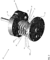
FIG. 2 is a perspective view of a fluid machine according to an embodiment; -
FIG. 3 is an exploded view of the first rotor and the second rotor according to an embodiment; -
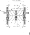
FIG. 4 is a cross-sectional view of the first rotor and the second rotor according to an embodiment; -
FIG. 5 is a cross-sectional view of the first rotor and the second rotor in a first scenario according to an embodiment; and -
FIG. 6 is a cross-sectional view of the first rotor and the second rotor in a second scenario according to an embodiment. - The detailed description explains embodiments of the disclosure, together with advantages and features, by way of example with reference to the drawings.
- Referring now to the
FIGS. 1 and2 , afluid machine 20 is illustrated. In the illustrated, non-limiting embodiment, thefluid machine 20 is an opposed screw compressor. However, other suitable embodiments of a fluid machine, such as a pump, fluid motor, or engine for example, are also within the scope of the disclosure. Thefluid machine 20 includes afirst rotor 22 intermeshed with asecond rotor 24. In an embodiment, thefirst rotor 22 is a male rotor having a male-lobed workingportion 26 and thesecond rotor 24 is a female rotor including a female-lobedportion 28. Alternatively, thefirst rotor 22 may be a female rotor and thesecond rotor 24 may be a male rotor. The workingportion 26 of thefirst rotor 22 includes at least one firsthelical lobe 30 and at least one secondhelical lobe 32. In the illustrated, non-limiting embodiment, thefirst rotor 22 includes twoseparate portions helical lobes 30 and the secondhelical lobes 32, respectively. - The
fluid machine 20 includes afirst shaft 38 fixed for rotation with thefirst rotor 22. Thefluid machine 20 further include acasing 40 rotatably supporting thefirst shaft 38 and at least partially enclosing thefirst rotor 22 and thesecond rotor 24. Afirst end 42 and asecond end 44 of thecasing 40 are configured to rotatably support thefirst shaft 38. Thefirst shaft 38 of the illustrated embodiments is directly coupled to anelectric motor 46 operable to drive rotation of thefirst shaft 38 about an axis X. Any suitable type ofelectric motor 46 is contemplated herein, including but not limited to an induction motor, permanent magnet (PM) motor, and switch reluctance motor for example. In an embodiment, thefirst rotor 22 is fixed to thefirst shaft 38 by a fastener, coupling, integral formation, interference fit, and /or any additional structures or methods known to a person having ordinary skill in the art (not shown), such that thefirst rotor 22 and thefirst shaft 38 rotate about axis X in unison. - The
fluid machine 20 additionally includes asecond shaft 48 operable to rotationally support thesecond rotor 24. Thesecond rotor 24 includes an axially extendingbore 50 within which thesecond shaft 48 is received. In an embodiment, thesecond shaft 48 is stationary or fixed relative to thecasing 40 and thesecond rotor 24 is configured to rotate about thesecond shaft 48. However, embodiments where thesecond shaft 48 is also rotatable relative to thecasing 40 are also contemplated herein. - With specific reference to
FIG. 2 , thefirst rotor 22 is shown as including afirst portion 34 having four firsthelical lobes 30 and asecond portion 36 having four secondhelical lobes 32. The illustrated, non-limiting embodiment, is intended as an example only, and it should be understood by a person of ordinary skill in the art that any suitable number of firsthelical lobes 30 and secondhelical lobes 32 are within the scope of the disclosure. As shown, the firsthelical lobes 30 and the secondhelical lobes 32 have opposite helical configurations. In the illustrated, non-limited embodiment, the firsthelical lobes 30 are left-handed and the secondhelical lobes 32 are right-handed. Alternatively, the firsthelical lobes 30 may be right-handed and the secondhelical lobes 32 may be left-handed. - By including
lobes helical lobes helical lobes helical lobes - The
second rotor 24 has afirst portion 52 configured to mesh with the firsthelical lobes 30 and asecond portion 54 configured to mesh with the secondhelical lobes 32. To achieve proper intermeshing engagement between thefirst rotor 22 and thesecond rotor 24, eachportion second rotor 24 includes one or more lobes 56 having an opposite configuration to the correspondinghelical lobes first rotor 22. In the illustrated, non-limiting embodiment, thefirst portion 52 of thesecond rotor 24 has at least one right-handedlobe 56a, and thesecond portion 54 of thesecond rotor 24 includes at least one left-handedlobe 56b. - In an embodiment, the
first portion 52 of thesecond rotor 24 is configured to rotate independently from thesecond portion 54 of thesecond rotor 24. However, embodiments where the first andsecond portions portion second rotor 24 may include any number of lobes 56. In an embodiment, the total number of lobes 56 formed in eachportion second rotor 24 is generally larger than a corresponding portion, 34 and 36, respectively, of thefirst rotor 22. For example, if thefirst rotor 22 includes four firsthelical lobes 30, thefirst portion 54 of thesecond rotor 24 configured to intermesh with the firsthelical lobes 30 may include fivehelical lobes 56a. However, embodiments where the total number of lobes 56 in aportion second rotor 24 is equal to a corresponding group of helical lobes (i.e. the firsthelical lobes 30 or the second helical lobes 32) of thefirst rotor 22 are also within the scope of the disclosure. - Returning to
FIG. 1 , thefluid machine 20 may include afirst shaft passage 58 extending axially through thefirst shaft 38 and asecond shaft passage 60 extending axially through a portion of thesecond shaft 48. Thefirst shaft passage 58 and/or thesecond shaft passage 60 communicate lubricant from asump 62, throughfirst shaft 38 and/orsecond shaft 48, out one or more radial passages (not shown), and along one or more surfaces of thefirst rotor 22 and/or thesecond rotor 24. Thefluid machine 20 further includes an axially-extending passage (not shown) defined between thesecond shaft 48 and thebore 50 formed in thesecond rotor 24. The passage is configured to allow lubricant to pass or circulate there through. In an embodiment, relatively high pressure discharge at first and second ends 42, 44 of thecasing 40, thefirst rotor 22, and thesecond rotor 24 and relatively low pressure suction at a central location of thefirst rotor 22 and thesecond rotor 24 urge lubricant through each of the passages. The circulation of lubricant through the passage disposed betweenbore 50 and thesecond shaft 48 provides internal bearing surfaces between each of the first andsecond portions second shaft 48 to reduce friction there between and further allow thefirst portion 52 of thesecond rotor 24 to rotate independently of thesecond portion 54 of thesecond rotor 24. - During operation of the
fluid machine 20 of one embodiment, a gas or other fluid, such as a low GWP refrigerant for example, is drawn to a central location by a suction process generated by thefluid machine 20. Rotation of thefirst rotor 22 and thesecond rotor 24 compresses the refrigerant and forces the refrigerant toward first and second ends 42, 44 of thecasing 40 between the sealed surfaces of themeshed rotors helical rotors casing 40 and discharged through thesecond end 44 of thecasing 40. The discharged refrigerant passes through theelectric motor 46 and out of adischarge passage 64. - With reference now to
FIGS. 3-6 , thefirst rotor 22 and thesecond rotor 24 are illustrated in more detail. To avoid interference between thelobes 56a of thefirst portion 52 of thesecond rotor 24 and thelobes 32 of thesecond portion 36 of thefirst rotor 22, or alternatively, interference between thelobes 56b of thesecond portion 52 of thesecond rotor 24 and thelobes 30 of thefirst portion 34 of thefirst rotor 22, at least one of the first andsecond rotors first spacer 70a is located between the first,upper portion 34 and the second,lower portion 36 of thefirst rotor 22 and asecond spacer 70b is located between the first,upper portion 52 and the second,lower portion 54 of thesecond rotor 24. However, embodiments where only one of the first andsecond rotor - The one or more spacers may be formed from any suitable material, including but not limited to a plastic or metal for example. In an embodiment, the spacer 70 is generally circular in shape and has a centrally located opening extending there through. An inner diameter of the opening is greater than the diameter of a corresponding
shaft rotor shaft shaft bore 50 for example, formed in therotor - With reference to
FIG. 4 , thefirst portion 34 of thefirst rotor 22 has a first upper rotor length M1, and thesecond portion 36 of thefirst rotor 22 has a first lower rotor length M2. Similarly, thefirst portion 52 of thesecond rotor 24 has a second upper rotor length F1, and thesecond portion 54 of thesecond rotor 24 has a second lower rotor length F2. A first upper rotor axial clearance C1 is defined between thefirst portion 34 of thefirst rotor 22 and an adjacent surface of therotor case 40, and a first lower rotor axial clearance C2 is defined between thesecond portion 36 of thefirst rotor 22 and an adjacent surface of therotor case 40. Similarly, a second upper rotor axial clearance D1 is defined between thefirst portion 52 of thesecond rotor 24 and an adjacent surface of therotor case 40, and a second lower rotor axial clearance D2 is defined between thesecond portion 54 of thesecond rotor 24 and an adjacent surface of therotor case 40. - The thickness of the at least one spacer 70 should be selected to avoid interference between
lobes lobes machine 20 in various worst case scenarios. In a first scenario, illustrated inFIG. 5 , thefirst portion 34 of thefirst rotor 22 is arranged in contact with the surface of therotor casing 40 and thesecond portion 54 of thesecond rotor 24 is arranged in contact with surface of the rotor casing. In such embodiments, the sum of the first upper rotor length M1 and the thickness T1 of thespacer 70a positioned between the first andsecond portions first rotor 22 must be greater than the sum of the second upper rotor length F1, the second upper rotor axial clearance D1, and the second lower rotor axial clearance D2. Expressed differently, the thickness T1 of thespacer 70a is greater than the summation of the second upper rotor length F1, the second upper rotor axial clearance D1 and the second lower rotor axial clearance D2 minus the first upper rotor length M1. - In this first scenario, the sum of the second lower rotor length F2 and the thickness T2 of the
spacer 70b positioned between the first andsecond portions second rotor 24 must be greater than the sum of the first lower rotor length F2, the first upper rotor axial clearance C1, and the first lower rotor axial clearance C2. Expressed differently, the thickness T2 of thespacer 70b is greater than the summation of the first lower rotor length M2, the first upper rotor axial clearance C1 and the first lower rotor axial clearance C2 minus the second lower rotor length F2. - In a second scenario, illustrated in
FIG. 6 , thesecond portion 36 of thefirst rotor 22 is arranged in contact with the surface of therotor casing 40 and thefirst portion 52 of thesecond rotor 24 is arranged in contact with surface of the rotor casing. In such embodiments, the sum of the first lower rotor length M2 and the thickness T1 of thespacer 70a positioned between the first andsecond portions first rotor 22 must be greater than the sum of the second lower rotor length F2, the second upper rotor axial clearance D1, and the second lower rotor axial clearance D2. Expressed differently, the thickness T1 of thespacer 70a is greater than the summation of the second lower rotor length F2, the second upper rotor axial clearance D1 and the second lower rotor axial clearance D2 minus the first lower rotor length M2. - Similarly, in this second scenario, the sum of the second upper rotor length F1 and the thickness T2 of the
spacer 70b positioned between the first andsecond portions second rotor 24 must be greater than the sum of the first upper rotor length M1, the first upper rotor axial clearance C1, and the first lower rotor axial clearance C2. Expressed differently, the thickness T2 of thespacer 70b is greater than the summation of the first upper rotor length M1, the first upper rotor axial clearance C1 and the first lower rotor axial clearance C2 minus the second upper rotor length F1. If the thickness of a spacer varies between the first scenario and the second scenario, the greater thickness should be selected. - In an embodiment, the thickness of the
first spacer 70a and the thickness of thesecond spacer 70b may be selected such that the first upper rotor axial clearance C1 is equal to the second upper rotor axial clearance D1 and the first lower rotor axial clearance C2 is equal to the second lower rotor axial clearance D2. In such embodiments, the thickness of thefirst spacer 70a is equal to a total axial length L of therotor case 40 minus the summation of the first upper rotor length M1, the first lower rotor length M1, the first upper rotor axial clearance C1 and the first lower rotor axial clearance C2. Similarly, the thickness of thesecond spacer 70b is equal to the total axial length L of therotor case 40 minus the summation of the second upper rotor length F1, the second lower rotor length F1, the second upper rotor axial clearance D1 and the second lower rotor axial clearance D2. - Inclusion of one or more spacers 70 as described herein provides a more secure operation of the
fluid machine 20 with minimal additional cost. Not only are the one or more spacers 70 operable to avoid unintentional interference between lobes, but also to control the axial clearance of themachine 20. Further, use of such spacers is most cost effective than restricting the manufacturing tolerances of themachine 20 to avoid such interference. - While the disclosure has been described in detail in connection with only a limited number of embodiments, it should be readily understood that the disclosure is not limited to such disclosed embodiments. Rather, the disclosure can be modified to incorporate any number of variations, alterations, substitutions or equivalent arrangements not heretofore described, but which are commensurate with the spirit and scope of the disclosure. Additionally, while various embodiments of the disclosure have been described, it is to be understood that aspects of the disclosure may include only some of the described embodiments. Accordingly, the disclosure is not to be seen as limited by the foregoing description, but is only limited by the scope of the appended claims.
Claims (15)
- A fluid machine comprising:a first rotor rotatable about a first axis, the first rotor including a first portion and a second portion;a second rotor rotatable about a second axis, the second rotor including a first portion and a second portion; andat least one spacer associated with the first rotor and the second rotor to limit intermeshing engagement between the first rotor and the second rotor.
- The fluid machine of claim 1, where the at least one spacer is positioned between the first portion and the second portion of at least one of the first rotor and the second rotor to prevent the first portion of the second rotor from engaging the second portion of the first rotor.
- The fluid machine of claim 2, where the at least one spacer is positioned between the first portion and second portion of the second rotor to prevent the first portion of the second rotor from engaging the second portion of the first rotor; or
where the at least one spacer is positioned between the first portion and second portion of the first rotor to prevent the first portion of the first rotor from engaging the second portion of the second rotor. - The fluid machine of any of the preceding claims, further comprising:a casing:a first shaft for supporting the first rotor relative to the casing; anda second shaft for supporting the second rotor relative to the casing, wherein the at least one spacer is mounted concentrically with at least one of the first shaft and the second shaft.
- The fluid machine of any of the preceding claims, wherein the first portion of the first rotor has a first upper rotor length M1, the second portion of the first rotor has a first lower rotor length M2, the first portion of the second rotor has a second upper rotor length F1, the second portion of the second rotor has a second lower rotor length F2, a first upper rotor axial clearance C1 between the first portion of the first rotor and the casing, a first lower rotor axial clearance C2 between the second portion of the first rotor and the casing, a second upper rotor axial clearance D1 between the first portion of the second rotor and the casing, and a second lower rotor axial clearance D2 between the second portion of the second rotor and the casing.
- The fluid machine of claim 5, wherein the at least one spacer has an axial thickness such that the first upper rotor axial clearance C1 is equal to the second upper rotor axial clearance D1 and the first lower rotor axial clearance C2 is equal to the second lower rotor axial clearance D2.
- The fluid machine of claim 5 or 6, wherein an axial thickness of the at least one spacer is selected based on an arrangement of the first rotor and second rotor.
- The fluid machine of claim 7, wherein the at least one spacer is positioned between the first portion and the second portion of the first rotor, and an axial thickness of the spacer is greater than a summation of the second upper rotor length F1, the second upper rotor axial clearance D1 and the second lower rotor axial clearance D2 minus the first upper rotor length M1; or
wherein the at least one spacer is positioned between the first portion and the second portion of the first rotor, and an axial thickness of the spacer is greater than a summation of the second lower rotor length F2, the second upper rotor axial clearance D1 and the second lower rotor axial clearance D2 minus the first lower rotor length M2; or
wherein the at least one spacer is positioned between the first portion and the second portion of the second rotor, and an axial thickness of the spacer is greater than a summation of the first lower rotor length M2, the first upper rotor axial clearance C1 and the first lower rotor axial clearance C2 minus the second lower rotor length F2; or
wherein the at least one spacer is positioned between the first portion and the second portion of the second rotor, and an axial thickness of the spacer is greater than a summation of the first upper rotor length M1, the first upper rotor axial clearance C1 and the first lower rotor axial clearance C2 minus the second upper rotor length F1. - A fluid machine comprising:a first rotor rotatable about a first axis;a second rotor rotatable about a second axis;at least one spacer associated with the first rotor and the second rotor to limit intermeshing engagement between the first rotor and the second rotor;a motor for driving rotation of at least one of the first rotor and the second rotor; anda casing for rotatably supporting at least one of the first rotor and the second rotor.
- The fluid machine of claim 9, wherein the at least one spacer is mounted concentrically with at least one of the first shaft and the second shaft.
- The fluid machine of claim 9 or 10, wherein the first rotor includes a first portion and a second portion and the second rotor includes a first portion and a second portion.
- The fluid machine of claim 11, wherein the at least one spacer is positioned between the first portion and second portion of the second rotor to prevent the first portion of the second rotor from engaging the second portion of the first rotor.
- The fluid machine of claim 12, wherein the at least one spacer is positioned between the first portion and second portion of the first rotor to prevent the first portion of the first rotor from engaging the second portion of the second rotor.
- The fluid machine of claim 11, wherein the at least one spacer includes a first spacer positioned between the first portion and second portion of the first rotor and a second spacer positioned between the first portion and second portion of the second rotor, the first spacer having a first thickness and the second spacer having a second thickness different from the first thickness.
- The fluid machine of any of claims 11 to 14, wherein a clearance between the first rotor and the casing is equal to a clearance between the second rotor and the casing.
Applications Claiming Priority (1)
| Application Number | Priority Date | Filing Date | Title |
|---|---|---|---|
| US201762580744P | 2017-11-02 | 2017-11-02 |
Publications (3)
| Publication Number | Publication Date |
|---|---|
| EP3489515A2 true EP3489515A2 (en) | 2019-05-29 |
| EP3489515A3 EP3489515A3 (en) | 2019-08-21 |
| EP3489515B1 EP3489515B1 (en) | 2025-04-02 |
Family
ID=64048973
Family Applications (1)
| Application Number | Title | Priority Date | Filing Date |
|---|---|---|---|
| EP18203802.6A Active EP3489515B1 (en) | 2017-11-02 | 2018-10-31 | Opposed screw compressor having non-interference system |
Country Status (3)
| Country | Link |
|---|---|
| US (1) | US11149732B2 (en) |
| EP (1) | EP3489515B1 (en) |
| CN (1) | CN109751240B (en) |
Families Citing this family (7)
| Publication number | Priority date | Publication date | Assignee | Title |
|---|---|---|---|---|
| WO2020162046A1 (en) * | 2019-02-06 | 2020-08-13 | 株式会社日立産機システム | Multi-stage screw compressor |
| CN112797001B (en) * | 2021-02-26 | 2024-11-15 | 珠海格力电器股份有限公司 | Rotor assemblies, compressors and air conditioners |
| CN112780553B (en) * | 2021-02-26 | 2025-12-23 | 珠海格力电器股份有限公司 | Rotor assembly, compressor and air conditioner |
| CN112780554B (en) * | 2021-02-26 | 2026-03-27 | 珠海格力电器股份有限公司 | Compressors and air conditioners |
| CN112780560A (en) * | 2021-02-26 | 2021-05-11 | 珠海格力电器股份有限公司 | Rotor subassembly, compressor and air conditioner |
| CN112780557A (en) * | 2021-02-26 | 2021-05-11 | 珠海格力电器股份有限公司 | A rotor structure, compressor and air conditioner |
| CN115559905A (en) * | 2022-10-25 | 2023-01-03 | 珠海格力电器股份有限公司 | Two-stage screw compressor and air conditioning unit |
Family Cites Families (25)
| Publication number | Priority date | Publication date | Assignee | Title |
|---|---|---|---|---|
| US1430894A (en) | 1920-04-13 | 1922-10-03 | William E Quimby Inc | Screw pump |
| US1701166A (en) | 1927-06-07 | 1929-02-05 | Sinclair Refining Co | Hot-oil pump |
| CH322415A (en) | 1948-12-07 | 1957-06-15 | Dresser Ind | Volumetric machine |
| US2804260A (en) | 1949-07-11 | 1957-08-27 | Svenska Rotor Maskiner Ab | Engines of screw rotor type |
| US2659239A (en) * | 1949-10-07 | 1953-11-17 | Jarvis C Marble | Independent synchronization |
| US2714857A (en) | 1951-09-04 | 1955-08-09 | Roper Corp Geo D | Gear pump |
| DK98144C (en) | 1958-02-27 | 1964-03-02 | Svenska Rotor Maskiner Ab | Multi-stage compression or expansion machine with screw rotors. |
| GB1220054A (en) | 1967-02-06 | 1971-01-20 | Svenska Rotor Maskiner Ab | Two-stage compressor of the meshing screw rotor type |
| US3589843A (en) | 1969-02-14 | 1971-06-29 | Warren Pumps Inc | Rotary pump with intermeshing helical ribs |
| DE2550360A1 (en) * | 1975-11-10 | 1977-05-12 | England Will Clarke | Wide range multiple circuit energy conversion valve - has inlet and outlet stages of unequal constant volume displacement |
| ZA852093B (en) * | 1984-03-21 | 1986-05-28 | Wassan Pty Ltd | Fluid motor or pump |
| GB8605033D0 (en) | 1986-02-28 | 1986-04-09 | Shell Int Research | Fluid driven pumping apparatus |
| US4828036A (en) | 1987-01-05 | 1989-05-09 | Shell Oil Company | Apparatus and method for pumping well fluids |
| JP3373286B2 (en) * | 1994-03-17 | 2003-02-04 | 栃木富士産業株式会社 | compressor |
| DE19519247C2 (en) * | 1995-05-25 | 2000-08-31 | Guenter Kirsten | Screw compressor |
| WO2002033262A1 (en) * | 2000-10-18 | 2002-04-25 | Leybold Vakuum Gmbh | Multi-stage helical screw rotor |
| DE102006021704B4 (en) * | 2006-05-10 | 2018-01-04 | Gea Refrigeration Germany Gmbh | Screw compressor for large power outputs |
| JP4623089B2 (en) | 2007-12-20 | 2011-02-02 | ダイキン工業株式会社 | Screw compressor |
| EP2216501A1 (en) | 2009-02-10 | 2010-08-11 | BP Exploration Operating Company Limited | Pump |
| US20110158841A1 (en) * | 2009-12-28 | 2011-06-30 | Sunny King Machinery Co., Ltd. | Screw Pump with Anti-Turbulent Structure |
| CN102220974B (en) | 2011-07-29 | 2016-06-08 | 四川省机械研究设计院 | Bearing-free Quimby pump |
| US9453396B2 (en) | 2011-12-02 | 2016-09-27 | Raymond C. Davis | Oil well pump apparatus |
| US9470228B2 (en) | 2012-07-03 | 2016-10-18 | Brian J. O'Connor | Multiple segment lobe pump |
| CN104005950B (en) | 2013-02-26 | 2016-04-13 | 复盛股份有限公司 | Multi-stage Helical Rotor Mechanism of Fluid Machinery |
| US8864486B2 (en) * | 2013-03-15 | 2014-10-21 | Corning Incorporated | Twin screw shaft spacer bearing |
-
2018
- 2018-10-29 US US16/173,887 patent/US11149732B2/en active Active
- 2018-10-31 EP EP18203802.6A patent/EP3489515B1/en active Active
- 2018-11-01 CN CN201811294804.1A patent/CN109751240B/en active Active
Non-Patent Citations (1)
| Title |
|---|
| None |
Also Published As
| Publication number | Publication date |
|---|---|
| EP3489515B1 (en) | 2025-04-02 |
| US20190128260A1 (en) | 2019-05-02 |
| CN109751240A (en) | 2019-05-14 |
| CN109751240B (en) | 2022-08-30 |
| US11149732B2 (en) | 2021-10-19 |
| EP3489515A3 (en) | 2019-08-21 |
Similar Documents
| Publication | Publication Date | Title |
|---|---|---|
| US11149732B2 (en) | Opposed screw compressor having non-interference system | |
| US11268512B2 (en) | Fluid machine with helically lobed rotors | |
| EP3701151B1 (en) | Lubricant supply passage for compressor background | |
| KR101110225B1 (en) | Scroll compressor | |
| US20190128261A1 (en) | Opposed screw compressor with staggered screw rotor | |
| US8075289B2 (en) | Scroll-type fluid machine including thrust receiving device | |
| JP7818003B2 (en) | Compressors and air conditioners | |
| CN108930649B (en) | Compressor with oil management system | |
| KR102060474B1 (en) | Scroll compressor | |
| US11421688B2 (en) | Vane compressor with elastic member protruding into the cylinder | |
| US11365735B2 (en) | Internal discharge gas passage for compressor | |
| JP2012184709A (en) | Scroll compressor | |
| KR20200030390A (en) | Motor operated compressor | |
| CN108071591B (en) | refrigerant compressor | |
| EP3450754A1 (en) | Open type refrigerant compressor | |
| EP3784907B1 (en) | Screw compressor with external motor rotor | |
| EP3555477B1 (en) | Screw compressor with magnetic gear | |
| JP7799241B2 (en) | Scroll-type fluid machinery | |
| WO2025052980A1 (en) | Screw compressor and gas compression facility |
Legal Events
| Date | Code | Title | Description |
|---|---|---|---|
| PUAI | Public reference made under article 153(3) epc to a published international application that has entered the european phase |
Free format text: ORIGINAL CODE: 0009012 |
|
| STAA | Information on the status of an ep patent application or granted ep patent |
Free format text: STATUS: THE APPLICATION HAS BEEN PUBLISHED |
|
| AK | Designated contracting states |
Kind code of ref document: A2 Designated state(s): AL AT BE BG CH CY CZ DE DK EE ES FI FR GB GR HR HU IE IS IT LI LT LU LV MC MK MT NL NO PL PT RO RS SE SI SK SM TR |
|
| AX | Request for extension of the european patent |
Extension state: BA ME |
|
| PUAL | Search report despatched |
Free format text: ORIGINAL CODE: 0009013 |
|
| AK | Designated contracting states |
Kind code of ref document: A3 Designated state(s): AL AT BE BG CH CY CZ DE DK EE ES FI FR GB GR HR HU IE IS IT LI LT LU LV MC MK MT NL NO PL PT RO RS SE SI SK SM TR |
|
| AX | Request for extension of the european patent |
Extension state: BA ME |
|
| RIC1 | Information provided on ipc code assigned before grant |
Ipc: F04C 18/16 20060101AFI20190715BHEP Ipc: F04C 23/00 20060101ALI20190715BHEP |
|
| STAA | Information on the status of an ep patent application or granted ep patent |
Free format text: STATUS: REQUEST FOR EXAMINATION WAS MADE |
|
| 17P | Request for examination filed |
Effective date: 20200219 |
|
| RBV | Designated contracting states (corrected) |
Designated state(s): AL AT BE BG CH CY CZ DE DK EE ES FI FR GB GR HR HU IE IS IT LI LT LU LV MC MK MT NL NO PL PT RO RS SE SI SK SM TR |
|
| STAA | Information on the status of an ep patent application or granted ep patent |
Free format text: STATUS: EXAMINATION IS IN PROGRESS |
|
| 17Q | First examination report despatched |
Effective date: 20220307 |
|
| GRAP | Despatch of communication of intention to grant a patent |
Free format text: ORIGINAL CODE: EPIDOSNIGR1 |
|
| STAA | Information on the status of an ep patent application or granted ep patent |
Free format text: STATUS: GRANT OF PATENT IS INTENDED |
|
| INTG | Intention to grant announced |
Effective date: 20241022 |
|
| GRAS | Grant fee paid |
Free format text: ORIGINAL CODE: EPIDOSNIGR3 |
|
| GRAA | (expected) grant |
Free format text: ORIGINAL CODE: 0009210 |
|
| STAA | Information on the status of an ep patent application or granted ep patent |
Free format text: STATUS: THE PATENT HAS BEEN GRANTED |
|
| AK | Designated contracting states |
Kind code of ref document: B1 Designated state(s): AL AT BE BG CH CY CZ DE DK EE ES FI FR GB GR HR HU IE IS IT LI LT LU LV MC MK MT NL NO PL PT RO RS SE SI SK SM TR |
|
| REG | Reference to a national code |
Ref country code: GB Ref legal event code: FG4D |
|
| REG | Reference to a national code |
Ref country code: CH Ref legal event code: EP |
|
| REG | Reference to a national code |
Ref country code: DE Ref legal event code: R096 Ref document number: 602018080665 Country of ref document: DE |
|
| REG | Reference to a national code |
Ref country code: IE Ref legal event code: FG4D |
|
| REG | Reference to a national code |
Ref country code: NL Ref legal event code: MP Effective date: 20250402 |
|
| PG25 | Lapsed in a contracting state [announced via postgrant information from national office to epo] |
Ref country code: NL Free format text: LAPSE BECAUSE OF FAILURE TO SUBMIT A TRANSLATION OF THE DESCRIPTION OR TO PAY THE FEE WITHIN THE PRESCRIBED TIME-LIMIT Effective date: 20250402 |
|
| REG | Reference to a national code |
Ref country code: AT Ref legal event code: MK05 Ref document number: 1781493 Country of ref document: AT Kind code of ref document: T Effective date: 20250402 |
|
| PG25 | Lapsed in a contracting state [announced via postgrant information from national office to epo] |
Ref country code: PT Free format text: LAPSE BECAUSE OF FAILURE TO SUBMIT A TRANSLATION OF THE DESCRIPTION OR TO PAY THE FEE WITHIN THE PRESCRIBED TIME-LIMIT Effective date: 20250804 Ref country code: ES Free format text: LAPSE BECAUSE OF FAILURE TO SUBMIT A TRANSLATION OF THE DESCRIPTION OR TO PAY THE FEE WITHIN THE PRESCRIBED TIME-LIMIT Effective date: 20250402 Ref country code: FI Free format text: LAPSE BECAUSE OF FAILURE TO SUBMIT A TRANSLATION OF THE DESCRIPTION OR TO PAY THE FEE WITHIN THE PRESCRIBED TIME-LIMIT Effective date: 20250402 |
|
| REG | Reference to a national code |
Ref country code: LT Ref legal event code: MG9D |
|
| PG25 | Lapsed in a contracting state [announced via postgrant information from national office to epo] |
Ref country code: NO Free format text: LAPSE BECAUSE OF FAILURE TO SUBMIT A TRANSLATION OF THE DESCRIPTION OR TO PAY THE FEE WITHIN THE PRESCRIBED TIME-LIMIT Effective date: 20250702 Ref country code: GR Free format text: LAPSE BECAUSE OF FAILURE TO SUBMIT A TRANSLATION OF THE DESCRIPTION OR TO PAY THE FEE WITHIN THE PRESCRIBED TIME-LIMIT Effective date: 20250703 |
|
| PG25 | Lapsed in a contracting state [announced via postgrant information from national office to epo] |
Ref country code: PL Free format text: LAPSE BECAUSE OF FAILURE TO SUBMIT A TRANSLATION OF THE DESCRIPTION OR TO PAY THE FEE WITHIN THE PRESCRIBED TIME-LIMIT Effective date: 20250402 |
|
| PG25 | Lapsed in a contracting state [announced via postgrant information from national office to epo] |
Ref country code: BG Free format text: LAPSE BECAUSE OF FAILURE TO SUBMIT A TRANSLATION OF THE DESCRIPTION OR TO PAY THE FEE WITHIN THE PRESCRIBED TIME-LIMIT Effective date: 20250402 |
|
| PG25 | Lapsed in a contracting state [announced via postgrant information from national office to epo] |
Ref country code: HR Free format text: LAPSE BECAUSE OF FAILURE TO SUBMIT A TRANSLATION OF THE DESCRIPTION OR TO PAY THE FEE WITHIN THE PRESCRIBED TIME-LIMIT Effective date: 20250402 |
|
| PG25 | Lapsed in a contracting state [announced via postgrant information from national office to epo] |
Ref country code: AT Free format text: LAPSE BECAUSE OF FAILURE TO SUBMIT A TRANSLATION OF THE DESCRIPTION OR TO PAY THE FEE WITHIN THE PRESCRIBED TIME-LIMIT Effective date: 20250402 |
|
| PGFP | Annual fee paid to national office [announced via postgrant information from national office to epo] |
Ref country code: FR Payment date: 20250924 Year of fee payment: 8 |
|
| PG25 | Lapsed in a contracting state [announced via postgrant information from national office to epo] |
Ref country code: RS Free format text: LAPSE BECAUSE OF FAILURE TO SUBMIT A TRANSLATION OF THE DESCRIPTION OR TO PAY THE FEE WITHIN THE PRESCRIBED TIME-LIMIT Effective date: 20250702 |
|
| PG25 | Lapsed in a contracting state [announced via postgrant information from national office to epo] |
Ref country code: IS Free format text: LAPSE BECAUSE OF FAILURE TO SUBMIT A TRANSLATION OF THE DESCRIPTION OR TO PAY THE FEE WITHIN THE PRESCRIBED TIME-LIMIT Effective date: 20250802 |
|
| PG25 | Lapsed in a contracting state [announced via postgrant information from national office to epo] |
Ref country code: LV Free format text: LAPSE BECAUSE OF FAILURE TO SUBMIT A TRANSLATION OF THE DESCRIPTION OR TO PAY THE FEE WITHIN THE PRESCRIBED TIME-LIMIT Effective date: 20250402 |
|
| REG | Reference to a national code |
Ref country code: DE Ref legal event code: R097 Ref document number: 602018080665 Country of ref document: DE |
|
| PGFP | Annual fee paid to national office [announced via postgrant information from national office to epo] |
Ref country code: DE Payment date: 20250923 Year of fee payment: 8 |
|
| PG25 | Lapsed in a contracting state [announced via postgrant information from national office to epo] |
Ref country code: DK Free format text: LAPSE BECAUSE OF FAILURE TO SUBMIT A TRANSLATION OF THE DESCRIPTION OR TO PAY THE FEE WITHIN THE PRESCRIBED TIME-LIMIT Effective date: 20250402 Ref country code: SM Free format text: LAPSE BECAUSE OF FAILURE TO SUBMIT A TRANSLATION OF THE DESCRIPTION OR TO PAY THE FEE WITHIN THE PRESCRIBED TIME-LIMIT Effective date: 20250402 |
|
| PG25 | Lapsed in a contracting state [announced via postgrant information from national office to epo] |
Ref country code: CZ Free format text: LAPSE BECAUSE OF FAILURE TO SUBMIT A TRANSLATION OF THE DESCRIPTION OR TO PAY THE FEE WITHIN THE PRESCRIBED TIME-LIMIT Effective date: 20250402 |
|
| PG25 | Lapsed in a contracting state [announced via postgrant information from national office to epo] |
Ref country code: EE Free format text: LAPSE BECAUSE OF FAILURE TO SUBMIT A TRANSLATION OF THE DESCRIPTION OR TO PAY THE FEE WITHIN THE PRESCRIBED TIME-LIMIT Effective date: 20250402 |
|
| PG25 | Lapsed in a contracting state [announced via postgrant information from national office to epo] |
Ref country code: SK Free format text: LAPSE BECAUSE OF FAILURE TO SUBMIT A TRANSLATION OF THE DESCRIPTION OR TO PAY THE FEE WITHIN THE PRESCRIBED TIME-LIMIT Effective date: 20250402 Ref country code: RO Free format text: LAPSE BECAUSE OF FAILURE TO SUBMIT A TRANSLATION OF THE DESCRIPTION OR TO PAY THE FEE WITHIN THE PRESCRIBED TIME-LIMIT Effective date: 20250402 |
|
| PG25 | Lapsed in a contracting state [announced via postgrant information from national office to epo] |
Ref country code: IT Free format text: LAPSE BECAUSE OF FAILURE TO SUBMIT A TRANSLATION OF THE DESCRIPTION OR TO PAY THE FEE WITHIN THE PRESCRIBED TIME-LIMIT Effective date: 20250402 |
|
| PLBE | No opposition filed within time limit |
Free format text: ORIGINAL CODE: 0009261 |
|
| STAA | Information on the status of an ep patent application or granted ep patent |
Free format text: STATUS: NO OPPOSITION FILED WITHIN TIME LIMIT |
|
| REG | Reference to a national code |
Ref country code: CH Ref legal event code: L10 Free format text: ST27 STATUS EVENT CODE: U-0-0-L10-L00 (AS PROVIDED BY THE NATIONAL OFFICE) Effective date: 20260211 |
|
| 26N | No opposition filed |
Effective date: 20260105 |