EP3489499A1 - Structure interne d'un conduit d'éjection primaire - Google Patents
Structure interne d'un conduit d'éjection primaire Download PDFInfo
- Publication number
- EP3489499A1 EP3489499A1 EP18204991.6A EP18204991A EP3489499A1 EP 3489499 A1 EP3489499 A1 EP 3489499A1 EP 18204991 A EP18204991 A EP 18204991A EP 3489499 A1 EP3489499 A1 EP 3489499A1
- Authority
- EP
- European Patent Office
- Prior art keywords
- internal structure
- inner skin
- primary
- turbomachine
- wall
- Prior art date
- Legal status (The legal status is an assumption and is not a legal conclusion. Google has not performed a legal analysis and makes no representation as to the accuracy of the status listed.)
- Granted
Links
Images


Classifications
-
- F—MECHANICAL ENGINEERING; LIGHTING; HEATING; WEAPONS; BLASTING
- F01—MACHINES OR ENGINES IN GENERAL; ENGINE PLANTS IN GENERAL; STEAM ENGINES
- F01D—NON-POSITIVE DISPLACEMENT MACHINES OR ENGINES, e.g. STEAM TURBINES
- F01D25/00—Component parts, details, or accessories, not provided for in, or of interest apart from, other groups
- F01D25/24—Casings; Casing parts, e.g. diaphragms, casing fastenings
-
- F—MECHANICAL ENGINEERING; LIGHTING; HEATING; WEAPONS; BLASTING
- F01—MACHINES OR ENGINES IN GENERAL; ENGINE PLANTS IN GENERAL; STEAM ENGINES
- F01D—NON-POSITIVE DISPLACEMENT MACHINES OR ENGINES, e.g. STEAM TURBINES
- F01D25/00—Component parts, details, or accessories, not provided for in, or of interest apart from, other groups
- F01D25/30—Exhaust heads, chambers, or the like
-
- B—PERFORMING OPERATIONS; TRANSPORTING
- B64—AIRCRAFT; AVIATION; COSMONAUTICS
- B64D—EQUIPMENT FOR FITTING IN OR TO AIRCRAFT; FLIGHT SUITS; PARACHUTES; ARRANGEMENT OR MOUNTING OF POWER PLANTS OR PROPULSION TRANSMISSIONS IN AIRCRAFT
- B64D33/00—Arrangement in aircraft of power plant parts or auxiliaries not otherwise provided for
- B64D33/04—Arrangement in aircraft of power plant parts or auxiliaries not otherwise provided for of exhaust outlets or jet pipes
-
- F—MECHANICAL ENGINEERING; LIGHTING; HEATING; WEAPONS; BLASTING
- F01—MACHINES OR ENGINES IN GENERAL; ENGINE PLANTS IN GENERAL; STEAM ENGINES
- F01D—NON-POSITIVE DISPLACEMENT MACHINES OR ENGINES, e.g. STEAM TURBINES
- F01D25/00—Component parts, details, or accessories, not provided for in, or of interest apart from, other groups
- F01D25/28—Supporting or mounting arrangements, e.g. for turbine casing
-
- F—MECHANICAL ENGINEERING; LIGHTING; HEATING; WEAPONS; BLASTING
- F02—COMBUSTION ENGINES; HOT-GAS OR COMBUSTION-PRODUCT ENGINE PLANTS
- F02C—GAS-TURBINE PLANTS; AIR INTAKES FOR JET-PROPULSION PLANTS; CONTROLLING FUEL SUPPLY IN AIR-BREATHING JET-PROPULSION PLANTS
- F02C7/00—Features, components parts, details or accessories, not provided for in, or of interest apart form groups F02C1/00 - F02C6/00; Air intakes for jet-propulsion plants
- F02C7/24—Heat or noise insulation
-
- F—MECHANICAL ENGINEERING; LIGHTING; HEATING; WEAPONS; BLASTING
- F02—COMBUSTION ENGINES; HOT-GAS OR COMBUSTION-PRODUCT ENGINE PLANTS
- F02K—JET-PROPULSION PLANTS
- F02K1/00—Plants characterised by the form or arrangement of the jet pipe or nozzle; Jet pipes or nozzles peculiar thereto
- F02K1/04—Mounting of an exhaust cone in the jet pipe
-
- F—MECHANICAL ENGINEERING; LIGHTING; HEATING; WEAPONS; BLASTING
- F02—COMBUSTION ENGINES; HOT-GAS OR COMBUSTION-PRODUCT ENGINE PLANTS
- F02K—JET-PROPULSION PLANTS
- F02K1/00—Plants characterised by the form or arrangement of the jet pipe or nozzle; Jet pipes or nozzles peculiar thereto
- F02K1/78—Other construction of jet pipes
- F02K1/82—Jet pipe walls, e.g. liners
- F02K1/827—Sound absorbing structures or liners
-
- F—MECHANICAL ENGINEERING; LIGHTING; HEATING; WEAPONS; BLASTING
- F05—INDEXING SCHEMES RELATING TO ENGINES OR PUMPS IN VARIOUS SUBCLASSES OF CLASSES F01-F04
- F05D—INDEXING SCHEME FOR ASPECTS RELATING TO NON-POSITIVE-DISPLACEMENT MACHINES OR ENGINES, GAS-TURBINES OR JET-PROPULSION PLANTS
- F05D2220/00—Application
- F05D2220/30—Application in turbines
- F05D2220/32—Application in turbines in gas turbines
- F05D2220/323—Application in turbines in gas turbines for aircraft propulsion, e.g. jet engines
-
- F—MECHANICAL ENGINEERING; LIGHTING; HEATING; WEAPONS; BLASTING
- F05—INDEXING SCHEMES RELATING TO ENGINES OR PUMPS IN VARIOUS SUBCLASSES OF CLASSES F01-F04
- F05D—INDEXING SCHEME FOR ASPECTS RELATING TO NON-POSITIVE-DISPLACEMENT MACHINES OR ENGINES, GAS-TURBINES OR JET-PROPULSION PLANTS
- F05D2240/00—Components
- F05D2240/90—Mounting on supporting structures or systems
-
- F—MECHANICAL ENGINEERING; LIGHTING; HEATING; WEAPONS; BLASTING
- F05—INDEXING SCHEMES RELATING TO ENGINES OR PUMPS IN VARIOUS SUBCLASSES OF CLASSES F01-F04
- F05D—INDEXING SCHEME FOR ASPECTS RELATING TO NON-POSITIVE-DISPLACEMENT MACHINES OR ENGINES, GAS-TURBINES OR JET-PROPULSION PLANTS
- F05D2250/00—Geometry
- F05D2250/70—Shape
- F05D2250/75—Shape given by its similarity to a letter, e.g. T-shaped
-
- F—MECHANICAL ENGINEERING; LIGHTING; HEATING; WEAPONS; BLASTING
- F05—INDEXING SCHEMES RELATING TO ENGINES OR PUMPS IN VARIOUS SUBCLASSES OF CLASSES F01-F04
- F05D—INDEXING SCHEME FOR ASPECTS RELATING TO NON-POSITIVE-DISPLACEMENT MACHINES OR ENGINES, GAS-TURBINES OR JET-PROPULSION PLANTS
- F05D2260/00—Function
- F05D2260/30—Retaining components in desired mutual position
-
- F—MECHANICAL ENGINEERING; LIGHTING; HEATING; WEAPONS; BLASTING
- F05—INDEXING SCHEMES RELATING TO ENGINES OR PUMPS IN VARIOUS SUBCLASSES OF CLASSES F01-F04
- F05D—INDEXING SCHEME FOR ASPECTS RELATING TO NON-POSITIVE-DISPLACEMENT MACHINES OR ENGINES, GAS-TURBINES OR JET-PROPULSION PLANTS
- F05D2260/00—Function
- F05D2260/96—Preventing, counteracting or reducing vibration or noise
Definitions
- the present invention relates to an internal structure of a primary ejection duct of a turbomachine, a turbomachine comprising such an internal structure, and an aircraft comprising at least one such turbomachine.
- a turbomachine conventionally comprises, from upstream to downstream, an air inlet through which the air enters the turbomachine, a motor which ensures the combustion of air and fuel, and an ejection duct by which are evacuated the burned gases.
- Such a turbomachine generates noises during its operation.
- the turbomachine is surrounded by a nacelle comprising noise attenuator means, such as honeycomb structures.
- Low frequency sounds (between 300 Hz and 1000 Hz), especially those related to combustion, emitted by the turbine engine during take-off or landing form an important source of noise for the environment and to attenuate these noises, it is known to have low frequency sound attenuators devices in the structure of the primary ejection duct (called "plug" in English).
- the primary ejection duct is located in the extension of the engine and before the nozzle cone and its outer primary wall is in contact with the flow of flue gas from the engine.
- An object of the present invention is to provide an internal structure of a primary ejection duct of a turbomachine which comprises low frequency noise attenuation devices which is simple and easy to implement.
- the particular fixing of the inner wall facilitates the construction of said internal structure and the attenuation of the selected frequencies.
- the Fig. 1 shows an aircraft 10 which comprises a wing 12 under which is fixed a nacelle 14 in which is housed a turbomachine.
- X is the longitudinal axis of the turbomachine, positively oriented in the direction of travel of the aircraft 10 and which is also the longitudinal axis of the nacelle 14, is called Y the transverse axis which is horizontal when the aircraft 10 is on the ground, and Z the vertical axis or vertical height when the aircraft 10 is on the ground, these three directions X, Y and Z being orthogonal to each other and forming a reference orthonormal.
- the Fig. 2 shows the rear part of the turbomachine which forms a primary ejection duct 202 through which exhaust gases burned by the turbomachine and which is delimited externally by a primary nozzle 204 and inside by an internal structure 206 of the primary ejection duct 202.
- the primary ejection duct 202 and its internal structure 206 have a general shape consisting of surfaces of revolution about the longitudinal axis X of the turbomachine.
- a nozzle cone 208 At the rear of the internal structure 206 is fixed a nozzle cone 208.
- the Fig. 3 shows a front view and in perspective and of the internal structure 206 and the cone 208
- the Fig. 4 shows an enlargement of the internal structure 206.
- the internal structure 206 comprises a primary wall 302 pierced with holes 304 distributed on the surface of the primary wall 302.
- the primary wall 302 forms the outer surface of the internal structure 206, that is to say the one that forms the internal surface of the primary ejection duct 202.
- the internal structure 206 has an inner skin 305.
- the primary wall 302 and the inner skin 305 each consist of a surface of revolution which is, in this example, generally cylindrical and the inner skin 305 is arranged inside the primary wall. 302 so as to constitute a set of two coaxial surfaces.
- Fixing the inner skin 305 to the primary wall 302 is provided by spacers 307 fixed between the primary wall 302 and the inner skin 305 and angularly distributed around the perimeter of the inner skin 305.
- the spacers 307 are viewed in transparency on the Figs. 3 and 4 .
- the inner skin 305 extends between an upstream flank 402 facing the front of the turbomachine and a downstream flank 404 facing the rear of the turbomachine.
- Each flank 402, 404 here takes the form of a crown.
- each of the flanks 402 and 404 of the inner skin 305 is spaced from the primary wall 302 so as to leave free a passage 309 which allows the free flow of air between the inner skin 305 and the primary wall 302.
- the inner skin 305 is thus fixed only by the struts 307 which facilitates the implementation because it is not necessary to ensure the attachment between the primary wall 302 and the inner skin 305.
- the passage 309 allows to ensure better sound absorption due to vibrations of the inner wall 305 induced by the fact that its flanks 402 and 404 are not fixed.
- the volume between the inner wall 305 and the primary wall 302 form a box constituting a Helmholtz resonator.
- the spacers 307 are attached to the inner skin 305 by means of removable fastening means such as screws and for this purpose, the inner skin 305 and the spacer 307 have bores 405 provided for this purpose.
- the removable fastening means are elements that can be disassembled without damaging the inner skin 305 and the spacers 307.
- each spacer 307 to the primary wall 302 can be provided by removable fastening means such as screws or final like welding for example.
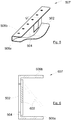
- each spacer 307 takes the form of a C-section with a central wall (504 at the Fig. 5 ) and two flaps (506a-b at the Fig. 5 ), but other shapes are possible such as pillars, or profiles of different shapes.
- the fixing of the spacer 307 to the inner skin 305 and to the primary wall 302 is effected between one of the flaps 506a-b of the C-section and according to the case the inner skin 305 or the primary wall 302.
- the spacer 307 takes the form of a C-profile whose central wall 504 is full.
- the Fig. 5 shows a spacer 507 with a C-profile according to a second particular embodiment and the Fig. 6 shows a spacer 607 with a C-shaped profile according to a third particular embodiment.
- the spacer 507 has a central wall 504 which has a through recess 502 to ensure better communication between the boxes.
- the spacer 607 has a central wall 504 with a through recess 502 and a flap 602 which is movable on the spacer 607 depending on the temperature between a closed position (in solid lines) in which it closes the through recess 502 and an open position (in phantom) in which it does not close the through recess 502.
- the opening of the flap 602 can be adapted to the ambient temperature and thus allows an optimal absorption of the sounds whatever the temperature.
- the shutter 602 is designed to open during an increase in temperature and close during a drop in temperature.
- the shutter 602 consists of a shape memory alloy and characteristics adapted to the temperature range to be covered.
- the inner skin 305 is pierced with drainage holes 406.
- the inner skin 305 is preferably formed by the machining of a single element, but it may also consist of several portions fixed to each other, in particular by welding.
Landscapes
- Engineering & Computer Science (AREA)
- Mechanical Engineering (AREA)
- Chemical & Material Sciences (AREA)
- Combustion & Propulsion (AREA)
- General Engineering & Computer Science (AREA)
- Aviation & Aerospace Engineering (AREA)
- Structures Of Non-Positive Displacement Pumps (AREA)
- Exhaust Silencers (AREA)
- Soundproofing, Sound Blocking, And Sound Damping (AREA)
Abstract
Description
- La présente invention concerne une structure interne d'un conduit d'éjection primaire d'une turbomachine, une turbomachine comportant une telle structure interne, ainsi qu'un aéronef comportant au moins une telle turbomachine.
- Une turbomachine comporte classiquement, de l'amont vers l'aval, une entrée d'air par laquelle l'air entre dans la turbomachine, un moteur qui assure la combustion de l'air et du carburant, et un conduit d'éjection par lequel sont évacués les gaz brûlés.
- Une telle turbomachine génère des bruits lors de son fonctionnement.
- Pour atténuer une partie des bruits, la turbomachine est entourée d'une nacelle comportant des moyens atténuateurs de bruit, comme par exemple des structures en nid d'abeilles.
- Les sons de basses fréquences (entre 300 Hz et 1000 Hz), notamment ceux liés à la combustion, émis par la turbomachine durant le décollage ou l'atterrissage forment une importante source de bruit pour l'environnement et pour atténuer ces bruits, il est connu de disposer des dispositifs atténuateurs de sons basses fréquences dans la structure du conduit d'éjection primaire (appelée « plug » en Anglais).
- Le conduit d'éjection primaire est situé dans le prolongement du moteur et avant le cône de tuyère et sa paroi primaire extérieure est en contact avec le flux de gaz brûlé en provenance du moteur.
- Le document
US-A-7,784,283 divulgue la réalisation de compartiments séparés par des cloisons de séparation sous la paroi primaire perforée du conduit d'éjection primaire afin de constituer des résonateurs de Helmholtz. - Un tel dispositif est efficace, cependant il est nécessaire de trouver de nouveaux modes de réalisation.
- Un objet de la présente invention est de proposer une structure interne d'un conduit d'éjection primaire d'une turbomachine qui comporte des dispositifs d'atténuation des bruits de basses fréquences qui soit simple et facile à mettre en oeuvre.
- A cet effet, est proposée une structure interne d'un conduit d'éjection primaire d'une turbomachine telle que revendiquée dans la revendication 1.
- La fixation particulière de la paroi intérieure facilite la construction de ladite structure interne et l'atténuation des fréquences choisies.
- Les caractéristiques de l'invention mentionnées ci-dessus, ainsi que d'autres, apparaîtront plus clairement à la lecture de la description suivante d'un exemple de réalisation, ladite description étant faite en relation avec les dessins joints, parmi lesquels :
- la
Fig. 1 est une vue de côté d'un aéronef selon l'invention, - la
Fig. 2 est une vue en perspective d'un conduit d'éjection primaire, - la
Fig. 3 est une vue en perspective d'une structure interne d'un conduit d'éjection primaire selon l'invention, - la
Fig. 4 est un agrandissement d'un détail de la structure interne de laFig. 3 , - la
Fig. 5 est une vue en perspective d'un exemple d'une entretoise mise en oeuvre dans la structure interne selon l'invention, et - la
Fig. 6 est une vue en coupe selon le plan VI de laFig. 5 d'une entretoise selon une variante de l'invention. - La
Fig. 1 montre un aéronef 10 qui comporte une aile 12 sous laquelle est fixée une nacelle 14 dans laquelle est logée une turbomachine. - Dans la description qui suit, et par convention, on appelle X l'axe longitudinal de la turbomachine, orienté positivement dans le sens d'avancement de l'aéronef 10 et qui est également l'axe longitudinal de la nacelle 14, on appelle Y l'axe transversal qui est horizontal lorsque l'aéronef 10 est au sol, et Z l'axe vertical ou hauteur verticale lorsque l'aéronef 10 est au sol, ces trois directions X, Y et Z étant orthogonales entre elles et formant un repère orthonormé.
- Dans la description qui suit, les termes relatifs à une position sont pris en référence au sens de déplacement des gaz dans la turbomachine c'est-à-dire de l'avant vers l'arrière de l'aéronef 10.
- La
Fig. 2 montre la partie arrière de la turbomachine qui forme un conduit d'éjection primaire 202 par lequel s'échappent les gaz brûlés par la turbomachine et qui est délimité à l'extérieur par une tuyère primaire 204 et à l'intérieur par une structure interne 206 du conduit d'éjection primaire 202. - Le conduit d'éjection primaire 202 comme sa structure interne 206 ont une forme générale consistant en des surfaces de révolution autour de l'axe longitudinal X de la turbomachine.
- A l'arrière de la structure interne 206 est fixé un cône de tuyère 208.
- La
Fig. 3 montre une vue de devant et en perspective et de la structure interne 206 et du cône 208, et laFig. 4 montre un agrandissement de la structure interne 206. - La structure interne 206 comporte une paroi primaire 302 percée de trous 304 répartis sur la surface de la paroi primaire 302. La paroi primaire 302 forme la surface extérieure de la structure interne 206 c'est-à-dire celle qui forme la surface interne du conduit d'éjection primaire 202.
- La structure interne 206 comporte une peau intérieure 305. La paroi primaire 302 et la peau intérieure 305 consistent chacune en une surface de révolution qui est, dans cet exemple, globalement cylindrique et la peau intérieure 305 est agencée à l'intérieur de la paroi primaire 302 de manière à constituer un ensemble de deux surfaces coaxiales.
- La fixation de la peau intérieure 305 à la paroi primaire 302 est assurée par des entretoises 307 fixées entre la paroi primaire 302 et la peau intérieure 305 et réparties angulairement sur le pourtour de la peau intérieure 305. Les entretoises 307 sont vues en transparence sur les
Figs. 3 et 4 . - La peau intérieure 305 s'étend entre un flanc amont 402 orienté vers l'avant de la turbomachine et un flanc aval 404 orienté vers l'arrière de la turbomachine. Chaque flanc 402, 404 prend ici la forme d'une couronne.
- Comme le montre la
Fig. 4 , la peau intérieure 305 et la paroi primaire 302 ne sont pas fixées l'une à l'autre. C'est-à-dire que chacun des flancs 402 et 404 de la peau intérieure 305 est à distance de la paroi primaire 302 de manière à laisser libre un passage 309 qui permet la libre circulation de l'air entre la peau intérieure 305 et la paroi primaire 302. - La peau intérieure 305 est ainsi fixée uniquement par les entretoises 307 ce qui facilite la mise en oeuvre car il n'est pas nécessaire d'assurer la fixation entre la paroi primaire 302 et la peau intérieure 305. En outre, le passage 309 permet d'assurer une meilleure absorption des sons du fait des vibrations de la paroi intérieure 305 induites par le fait que ses flancs 402 et 404 ne sont pas fixés.
- Entre deux entretoises 307 consécutives, le volume entre la paroi intérieure 305 et la paroi primaire 302 forme un caisson constituant un résonateur de Helmholtz.
- Afin de permettre un démontage facile de la peau intérieure 305, les entretoises 307 sont fixées à la peau intérieure 305 à l'aide de moyens de fixation amovibles comme par exemple des vis et à cette fin, la peau intérieure 305 et l'entretoise 307 présentent des alésages 405 prévus à cet effet. Les moyens de fixation amovibles sont des éléments qui peuvent être démontés sans endommager la peau intérieure 305 et les entretoises 307.
- La fixation de chaque entretoise 307 à la paroi primaire 302 peut être assurée par des moyens de fixation amovibles comme des vis ou définitifs comme le soudage par exemple.
- Dans le mode de réalisation de l'invention présenté sur les
Figs. 3 à 6 , chaque entretoise 307 prend la forme d'un profilé en C avec une paroi centrale (504 à laFig. 5 ) et deux rabats (506a-b à laFig. 5 ), mais d'autres formes sont possibles comme par exemple des piliers, ou des profilés de formes différentes. - Dans le cas d'une entretoise 307 ayant un profil en C, la fixation de l'entretoise 307 à la peau intérieure 305 et à la paroi primaire 302 s'effectue entre l'un des rabats 506a-b du profilé en C et selon le cas la peau intérieure 305 ou à la paroi primaire 302.
- Selon un premier mode de réalisation de l'invention représenté à la
Fig. 3 , l'entretoise 307 prend la forme d'un profilé en C dont la paroi centrale 504 est pleine. - La
Fig. 5 montre une entretoise 507 avec un profil en C selon un deuxième mode de réalisation particulier et laFig. 6 montre une entretoise 607 avec un profil en C selon un troisième mode de réalisation particulier. - Dans le mode de réalisation de la
Fig. 5 , l'entretoise 507 présente une paroi centrale 504 qui présente un évidement traversant 502 afin d'assurer une meilleure communication entre les caissons. - Dans le mode de réalisation de la
Fig. 6 , l'entretoise 607 présente une paroi centrale 504 avec un évidement traversant 502 et un volet 602 qui est mobile sur l'entretoise 607 en fonction de la température entre une position fermée (en traits pleins) dans laquelle il obture l'évidement traversant 502 et une position ouverte (en traits mixtes) dans laquelle il n'obture pas l'évidement traversant 502. Ainsi, comme les fréquences des sons varient en fonction de la température, l'ouverture du volet 602 peut être adaptée à la température ambiante et permet ainsi une absorption optimale des sons quelle que soit la température. D'une manière générale, le volet 602 est prévu pour s'ouvrir lors d'une augmentation de température et se fermer lors d'une baisse de température. - Afin que le positionnement du volet 602 soit en accord avec la température, le volet 602 est constitué d'un alliage à mémoire de forme et de caractéristiques adaptées à la plage de température devant être couverte.
- Afin d'assurer l'évacuation de l'eau qui peut s'infiltrer, la peau intérieure 305 est percée de trous de drainage 406.
- La peau intérieure 305 est préférentiellement constituée par l'usinage d'un seul élément, mais elle peut également être constituée de plusieurs portions fixées les unes aux autres, en particulier par soudage.
Claims (11)
- Structure interne (206) d'un conduit d'éjection primaire (202) d'une turbomachine, ladite structure interne (206) comportant :- une paroi primaire (302) consistant en une surface de révolution, laissant passer l'air à travers des orifices (304) et formant une surface interne du conduit d'éjection primaire (202),- une peau intérieure (305) consistant en une surface de révolution, agencée à l'intérieur de la paroi primaire (302) et s'étendant entre un flanc amont (402) destiné à être orienté vers l'avant de la turbomachine et un flanc aval (404) destiné à être orienté vers l'arrière de la turbomachine, et- une pluralité d'entretoises (307) réparties angulairement sur le pourtour de la peau intérieure (305) et fixées entre la paroi primaire (302) et la peau intérieure (305),la structure interne (206 étant caractérisée en ce que chacun des flancs (402, 404) de la peau intérieure (305) est à distance de la paroi primaire (302) de manière à laisser libre un passage (309) entre la peau intérieure (305) et la paroi primaire (302).
- Structure interne (206) selon la revendication 1, caractérisée en ce que les entretoises (307) sont fixées à la peau intérieure (305) à l'aide de moyens de fixation amovibles.
- Structure interne (206) selon l'une des revendications 1 à 2, caractérisée en ce que chaque entretoise (307) prend la forme d'un profilé en C avec une paroi centrale et deux rabats.
- Structure interne (206) selon la revendication 3, caractérisée en ce que la paroi centrale présente un évidement traversant (502).
- Structure interne (206) selon la revendication 4, caractérisée en ce que l'entretoise (607) comporte un volet (602) mobile en fonction de la température entre une position fermée dans laquelle il obture l'évidement traversant (502) et une position ouverte dans laquelle il n'obture pas l'évidement traversant (502).
- Structure interne (206) selon la revendication 5, caractérisée en ce que le volet (602) est constitué d'un alliage à mémoire de forme.
- Structure interne (206) selon l'une des revendications 1 à 6, caractérisée en ce que la peau intérieure (305) est percée de trous de drainage (406).
- Structure interne (206) selon l'une des revendications 1 à 7, caractérisée en ce que la peau intérieure (305) est constituée par l'usinage d'un seul élément.
- Structure interne (206) selon l'une des revendications 1 à 7, caractérisée en ce que la peau intérieure (305) est constituée de plusieurs portions fixées les unes aux autres.
- Turbomachine comportant un conduit d'éjection primaire (202) délimité à l'extérieur par une tuyère primaire (204) et à l'intérieur par une structure interne (206) selon l'une quelconque des revendications 1 à 9.
- Aéronef (10) comportant au moins une turbomachine selon la revendication 10.
Applications Claiming Priority (1)
| Application Number | Priority Date | Filing Date | Title |
|---|---|---|---|
| FR1761255A FR3074227B1 (fr) | 2017-11-28 | 2017-11-28 | Structure interne d'un conduit d'ejection primaire |
Publications (2)
| Publication Number | Publication Date |
|---|---|
| EP3489499A1 true EP3489499A1 (fr) | 2019-05-29 |
| EP3489499B1 EP3489499B1 (fr) | 2021-08-04 |
Family
ID=60955303
Family Applications (1)
| Application Number | Title | Priority Date | Filing Date |
|---|---|---|---|
| EP18204991.6A Active EP3489499B1 (fr) | 2017-11-28 | 2018-11-07 | Structure interne d'un conduit d'éjection primaire |
Country Status (4)
| Country | Link |
|---|---|
| US (1) | US10711650B2 (fr) |
| EP (1) | EP3489499B1 (fr) |
| CN (1) | CN109878741B (fr) |
| FR (1) | FR3074227B1 (fr) |
Families Citing this family (3)
| Publication number | Priority date | Publication date | Assignee | Title |
|---|---|---|---|---|
| US11136942B2 (en) * | 2018-09-14 | 2021-10-05 | Rohr, Inc. | Acoustic deep cavity centerbody |
| FR3115832B1 (fr) * | 2020-11-05 | 2023-04-21 | Safran Nacelles | Ensemble pour une turbomachine |
| US12559249B2 (en) | 2023-01-03 | 2026-02-24 | Rohr, Inc. | Engine exhaust center body with acoustic attenuation |
Citations (4)
| Publication number | Priority date | Publication date | Assignee | Title |
|---|---|---|---|---|
| EP1391597A2 (fr) * | 2002-08-14 | 2004-02-25 | Sener, Ingenieria Y Sistemas, S.A. | Conduite à réduction de bruit pour composants statiques de moteurs d'avion |
| US20100205930A1 (en) * | 2007-05-10 | 2010-08-19 | Eric Conete | Exhaust system for gas turbine |
| US7784283B2 (en) | 2006-05-03 | 2010-08-31 | Rohr, Inc. | Sound-absorbing exhaust nozzle center plug |
| EP3159522A1 (fr) * | 2015-10-20 | 2017-04-26 | Airbus Helicopters | Conduit d ejection de gaz a traitement acoustique, aeronef et procede de fabrication d'un tel conduit |
Family Cites Families (3)
| Publication number | Priority date | Publication date | Assignee | Title |
|---|---|---|---|---|
| US2988302A (en) * | 1959-01-14 | 1961-06-13 | Gen Sound Control Inc | Silencing means for aircraft |
| US4751979A (en) * | 1985-05-16 | 1988-06-21 | Airborne Express, Inc. | Engine noise suppression kit for the nacelles of a jet aircraft |
| WO2003099654A2 (fr) * | 2002-05-21 | 2003-12-04 | The Nordam Group, Inc. | Buse de reacteur a double flux bifurquee |
-
2017
- 2017-11-28 FR FR1761255A patent/FR3074227B1/fr active Active
-
2018
- 2018-11-07 EP EP18204991.6A patent/EP3489499B1/fr active Active
- 2018-11-19 US US16/195,142 patent/US10711650B2/en active Active
- 2018-11-26 CN CN201811418331.1A patent/CN109878741B/zh active Active
Patent Citations (4)
| Publication number | Priority date | Publication date | Assignee | Title |
|---|---|---|---|---|
| EP1391597A2 (fr) * | 2002-08-14 | 2004-02-25 | Sener, Ingenieria Y Sistemas, S.A. | Conduite à réduction de bruit pour composants statiques de moteurs d'avion |
| US7784283B2 (en) | 2006-05-03 | 2010-08-31 | Rohr, Inc. | Sound-absorbing exhaust nozzle center plug |
| US20100205930A1 (en) * | 2007-05-10 | 2010-08-19 | Eric Conete | Exhaust system for gas turbine |
| EP3159522A1 (fr) * | 2015-10-20 | 2017-04-26 | Airbus Helicopters | Conduit d ejection de gaz a traitement acoustique, aeronef et procede de fabrication d'un tel conduit |
Also Published As
| Publication number | Publication date |
|---|---|
| US10711650B2 (en) | 2020-07-14 |
| CN109878741A (zh) | 2019-06-14 |
| FR3074227B1 (fr) | 2020-02-28 |
| EP3489499B1 (fr) | 2021-08-04 |
| CN109878741B (zh) | 2022-03-22 |
| FR3074227A1 (fr) | 2019-05-31 |
| US20190162079A1 (en) | 2019-05-30 |
Similar Documents
| Publication | Publication Date | Title |
|---|---|---|
| CA2441058C (fr) | Nacelle de reacteur d`aeronef a attenuation acoustique | |
| EP1937954B1 (fr) | Turbomoteur a bruit de jet attenue | |
| CA2204589C (fr) | Inverseur de poussee de turboreacteur a portes munies d'aubes deflectrices | |
| EP3489499B1 (fr) | Structure interne d'un conduit d'éjection primaire | |
| EP3683429B1 (fr) | Structure interne d'un conduit d'ejection primaire | |
| WO2020160906A1 (fr) | Entree d'air d'une nacelle de turboreacteur d'aeronef comportant des ouvertures de ventilation d'un flux d'air chaud de degivrage | |
| EP3660299B1 (fr) | Structure d'absorption acoustique comprenant un système de drainage de liquide et ensemble propulsif comportant une telle structure d'absorption acoustique | |
| EP2819920B1 (fr) | Nacelle aplatie de turboréacteur | |
| EP2534358B1 (fr) | Dispositif d'ejection de gaz d'un moteur a turbine a gaz et moteur a turbine a gaz | |
| FR3069091B3 (fr) | Structure absorbante de sons | |
| EP3618057A1 (fr) | Structure absorbante de sons basses frequences pour une tuyere primaire d'une turbomachine d'un aeronef | |
| CA3126511A1 (fr) | Entree d'air d'une nacelle de turboreacteur d'aeronef comportant des ouvertures de ventilation d'un flux d'air chaud de degivrage | |
| EP3724076B1 (fr) | Lèvre d'entrée d'air de nacelle pour turboréacteur | |
| FR3061933B1 (fr) | Structure interne d'un conduit d'ejection primaire | |
| FR3078107A1 (fr) | Nacelle de turbomachine a parois acoustiquement poreuses | |
| CA2761601C (fr) | Turbomoteur comportant un cone de guidage des gaz d'echappement avec un attenuateur sonore | |
| EP3869023B1 (fr) | Structure interne d'un conduit d'éjection primaire comportant un séparateur dont la géometrie varie en fonction de la température | |
| FR3029573A1 (fr) | Inverseur de poussee pour un ensemble moteur d'aeronef, nacelle et ensemble moteur correspondants | |
| FR3088904A1 (fr) | Structure d’absorption acoustique comprenant au moins un élément acoustique indexé en rotation et ensemble propulsif d’aéronef comprenant ladite structure d’absorption acoustique | |
| FR3105553A1 (fr) | Système de traitement acoustique à au moins deux degrés de liberté comportant un revêtement quart d’onde permettant le passage d’ondes acoustiques dans un résonateur à mode de cavité | |
| FR3016390A1 (fr) | Aube supprimant les reflexions acoustiques, et turbomachine | |
| CA3126629A1 (fr) | Entree d'air d'une nacelle de turboreacteur d'aeronef comportant des ouvertures de ventilation d'un flux d'air chaud de degivrage | |
| FR3098552A1 (fr) | Turbomachine comportant une structure et une structure interne d’un conduit d’ejection primaire fixee a ladite structure |
Legal Events
| Date | Code | Title | Description |
|---|---|---|---|
| STAA | Information on the status of an ep patent application or granted ep patent |
Free format text: STATUS: EXAMINATION IS IN PROGRESS |
|
| PUAI | Public reference made under article 153(3) epc to a published international application that has entered the european phase |
Free format text: ORIGINAL CODE: 0009012 |
|
| 17P | Request for examination filed |
Effective date: 20181107 |
|
| AK | Designated contracting states |
Kind code of ref document: A1 Designated state(s): AL AT BE BG CH CY CZ DE DK EE ES FI FR GB GR HR HU IE IS IT LI LT LU LV MC MK MT NL NO PL PT RO RS SE SI SK SM TR |
|
| AX | Request for extension of the european patent |
Extension state: BA ME |
|
| RBV | Designated contracting states (corrected) |
Designated state(s): AL AT BE BG CH CY CZ DE DK EE ES FI FR GB GR HR HU IE IS IT LI LT LU LV MC MK MT NL NO PL PT RO RS SE SI SK SM TR |
|
| GRAP | Despatch of communication of intention to grant a patent |
Free format text: ORIGINAL CODE: EPIDOSNIGR1 |
|
| STAA | Information on the status of an ep patent application or granted ep patent |
Free format text: STATUS: GRANT OF PATENT IS INTENDED |
|
| INTG | Intention to grant announced |
Effective date: 20210521 |
|
| GRAS | Grant fee paid |
Free format text: ORIGINAL CODE: EPIDOSNIGR3 |
|
| GRAA | (expected) grant |
Free format text: ORIGINAL CODE: 0009210 |
|
| STAA | Information on the status of an ep patent application or granted ep patent |
Free format text: STATUS: THE PATENT HAS BEEN GRANTED |
|
| AK | Designated contracting states |
Kind code of ref document: B1 Designated state(s): AL AT BE BG CH CY CZ DE DK EE ES FI FR GB GR HR HU IE IS IT LI LT LU LV MC MK MT NL NO PL PT RO RS SE SI SK SM TR |
|
| REG | Reference to a national code |
Ref country code: GB Ref legal event code: FG4D Free format text: NOT ENGLISH |
|
| REG | Reference to a national code |
Ref country code: AT Ref legal event code: REF Ref document number: 1417213 Country of ref document: AT Kind code of ref document: T Effective date: 20210815 |
|
| REG | Reference to a national code |
Ref country code: CH Ref legal event code: EP |
|
| REG | Reference to a national code |
Ref country code: DE Ref legal event code: R096 Ref document number: 602018021132 Country of ref document: DE |
|
| REG | Reference to a national code |
Ref country code: IE Ref legal event code: FG4D Free format text: LANGUAGE OF EP DOCUMENT: FRENCH |
|
| REG | Reference to a national code |
Ref country code: LT Ref legal event code: MG9D |
|
| REG | Reference to a national code |
Ref country code: NL Ref legal event code: MP Effective date: 20210804 |
|
| REG | Reference to a national code |
Ref country code: AT Ref legal event code: MK05 Ref document number: 1417213 Country of ref document: AT Kind code of ref document: T Effective date: 20210804 |
|
| PG25 | Lapsed in a contracting state [announced via postgrant information from national office to epo] |
Ref country code: SE Free format text: LAPSE BECAUSE OF FAILURE TO SUBMIT A TRANSLATION OF THE DESCRIPTION OR TO PAY THE FEE WITHIN THE PRESCRIBED TIME-LIMIT Effective date: 20210804 Ref country code: RS Free format text: LAPSE BECAUSE OF FAILURE TO SUBMIT A TRANSLATION OF THE DESCRIPTION OR TO PAY THE FEE WITHIN THE PRESCRIBED TIME-LIMIT Effective date: 20210804 Ref country code: HR Free format text: LAPSE BECAUSE OF FAILURE TO SUBMIT A TRANSLATION OF THE DESCRIPTION OR TO PAY THE FEE WITHIN THE PRESCRIBED TIME-LIMIT Effective date: 20210804 Ref country code: FI Free format text: LAPSE BECAUSE OF FAILURE TO SUBMIT A TRANSLATION OF THE DESCRIPTION OR TO PAY THE FEE WITHIN THE PRESCRIBED TIME-LIMIT Effective date: 20210804 Ref country code: ES Free format text: LAPSE BECAUSE OF FAILURE TO SUBMIT A TRANSLATION OF THE DESCRIPTION OR TO PAY THE FEE WITHIN THE PRESCRIBED TIME-LIMIT Effective date: 20210804 Ref country code: BG Free format text: LAPSE BECAUSE OF FAILURE TO SUBMIT A TRANSLATION OF THE DESCRIPTION OR TO PAY THE FEE WITHIN THE PRESCRIBED TIME-LIMIT Effective date: 20211104 Ref country code: AT Free format text: LAPSE BECAUSE OF FAILURE TO SUBMIT A TRANSLATION OF THE DESCRIPTION OR TO PAY THE FEE WITHIN THE PRESCRIBED TIME-LIMIT Effective date: 20210804 Ref country code: LT Free format text: LAPSE BECAUSE OF FAILURE TO SUBMIT A TRANSLATION OF THE DESCRIPTION OR TO PAY THE FEE WITHIN THE PRESCRIBED TIME-LIMIT Effective date: 20210804 Ref country code: NO Free format text: LAPSE BECAUSE OF FAILURE TO SUBMIT A TRANSLATION OF THE DESCRIPTION OR TO PAY THE FEE WITHIN THE PRESCRIBED TIME-LIMIT Effective date: 20211104 Ref country code: PT Free format text: LAPSE BECAUSE OF FAILURE TO SUBMIT A TRANSLATION OF THE DESCRIPTION OR TO PAY THE FEE WITHIN THE PRESCRIBED TIME-LIMIT Effective date: 20211206 |
|
| PG25 | Lapsed in a contracting state [announced via postgrant information from national office to epo] |
Ref country code: PL Free format text: LAPSE BECAUSE OF FAILURE TO SUBMIT A TRANSLATION OF THE DESCRIPTION OR TO PAY THE FEE WITHIN THE PRESCRIBED TIME-LIMIT Effective date: 20210804 Ref country code: LV Free format text: LAPSE BECAUSE OF FAILURE TO SUBMIT A TRANSLATION OF THE DESCRIPTION OR TO PAY THE FEE WITHIN THE PRESCRIBED TIME-LIMIT Effective date: 20210804 Ref country code: GR Free format text: LAPSE BECAUSE OF FAILURE TO SUBMIT A TRANSLATION OF THE DESCRIPTION OR TO PAY THE FEE WITHIN THE PRESCRIBED TIME-LIMIT Effective date: 20211105 |
|
| PG25 | Lapsed in a contracting state [announced via postgrant information from national office to epo] |
Ref country code: NL Free format text: LAPSE BECAUSE OF FAILURE TO SUBMIT A TRANSLATION OF THE DESCRIPTION OR TO PAY THE FEE WITHIN THE PRESCRIBED TIME-LIMIT Effective date: 20210804 |
|
| PG25 | Lapsed in a contracting state [announced via postgrant information from national office to epo] |
Ref country code: DK Free format text: LAPSE BECAUSE OF FAILURE TO SUBMIT A TRANSLATION OF THE DESCRIPTION OR TO PAY THE FEE WITHIN THE PRESCRIBED TIME-LIMIT Effective date: 20210804 |
|
| REG | Reference to a national code |
Ref country code: DE Ref legal event code: R097 Ref document number: 602018021132 Country of ref document: DE |
|
| PG25 | Lapsed in a contracting state [announced via postgrant information from national office to epo] |
Ref country code: SM Free format text: LAPSE BECAUSE OF FAILURE TO SUBMIT A TRANSLATION OF THE DESCRIPTION OR TO PAY THE FEE WITHIN THE PRESCRIBED TIME-LIMIT Effective date: 20210804 Ref country code: SK Free format text: LAPSE BECAUSE OF FAILURE TO SUBMIT A TRANSLATION OF THE DESCRIPTION OR TO PAY THE FEE WITHIN THE PRESCRIBED TIME-LIMIT Effective date: 20210804 Ref country code: RO Free format text: LAPSE BECAUSE OF FAILURE TO SUBMIT A TRANSLATION OF THE DESCRIPTION OR TO PAY THE FEE WITHIN THE PRESCRIBED TIME-LIMIT Effective date: 20210804 Ref country code: EE Free format text: LAPSE BECAUSE OF FAILURE TO SUBMIT A TRANSLATION OF THE DESCRIPTION OR TO PAY THE FEE WITHIN THE PRESCRIBED TIME-LIMIT Effective date: 20210804 Ref country code: CZ Free format text: LAPSE BECAUSE OF FAILURE TO SUBMIT A TRANSLATION OF THE DESCRIPTION OR TO PAY THE FEE WITHIN THE PRESCRIBED TIME-LIMIT Effective date: 20210804 Ref country code: AL Free format text: LAPSE BECAUSE OF FAILURE TO SUBMIT A TRANSLATION OF THE DESCRIPTION OR TO PAY THE FEE WITHIN THE PRESCRIBED TIME-LIMIT Effective date: 20210804 |
|
| PLBE | No opposition filed within time limit |
Free format text: ORIGINAL CODE: 0009261 |
|
| STAA | Information on the status of an ep patent application or granted ep patent |
Free format text: STATUS: NO OPPOSITION FILED WITHIN TIME LIMIT |
|
| PG25 | Lapsed in a contracting state [announced via postgrant information from national office to epo] |
Ref country code: MC Free format text: LAPSE BECAUSE OF FAILURE TO SUBMIT A TRANSLATION OF THE DESCRIPTION OR TO PAY THE FEE WITHIN THE PRESCRIBED TIME-LIMIT Effective date: 20210804 |
|
| REG | Reference to a national code |
Ref country code: CH Ref legal event code: PL |
|
| 26N | No opposition filed |
Effective date: 20220506 |
|
| PG25 | Lapsed in a contracting state [announced via postgrant information from national office to epo] |
Ref country code: LU Free format text: LAPSE BECAUSE OF NON-PAYMENT OF DUE FEES Effective date: 20211107 Ref country code: IT Free format text: LAPSE BECAUSE OF FAILURE TO SUBMIT A TRANSLATION OF THE DESCRIPTION OR TO PAY THE FEE WITHIN THE PRESCRIBED TIME-LIMIT Effective date: 20210804 Ref country code: BE Free format text: LAPSE BECAUSE OF NON-PAYMENT OF DUE FEES Effective date: 20211130 |
|
| REG | Reference to a national code |
Ref country code: BE Ref legal event code: MM Effective date: 20211130 |
|
| PG25 | Lapsed in a contracting state [announced via postgrant information from national office to epo] |
Ref country code: SI Free format text: LAPSE BECAUSE OF FAILURE TO SUBMIT A TRANSLATION OF THE DESCRIPTION OR TO PAY THE FEE WITHIN THE PRESCRIBED TIME-LIMIT Effective date: 20210804 Ref country code: LI Free format text: LAPSE BECAUSE OF NON-PAYMENT OF DUE FEES Effective date: 20211130 Ref country code: CH Free format text: LAPSE BECAUSE OF NON-PAYMENT OF DUE FEES Effective date: 20211130 |
|
| PG25 | Lapsed in a contracting state [announced via postgrant information from national office to epo] |
Ref country code: IE Free format text: LAPSE BECAUSE OF NON-PAYMENT OF DUE FEES Effective date: 20211107 |
|
| PG25 | Lapsed in a contracting state [announced via postgrant information from national office to epo] |
Ref country code: CY Free format text: LAPSE BECAUSE OF FAILURE TO SUBMIT A TRANSLATION OF THE DESCRIPTION OR TO PAY THE FEE WITHIN THE PRESCRIBED TIME-LIMIT Effective date: 20210804 |
|
| PG25 | Lapsed in a contracting state [announced via postgrant information from national office to epo] |
Ref country code: HU Free format text: LAPSE BECAUSE OF FAILURE TO SUBMIT A TRANSLATION OF THE DESCRIPTION OR TO PAY THE FEE WITHIN THE PRESCRIBED TIME-LIMIT; INVALID AB INITIO Effective date: 20181107 |
|
| PG25 | Lapsed in a contracting state [announced via postgrant information from national office to epo] |
Ref country code: MK Free format text: LAPSE BECAUSE OF FAILURE TO SUBMIT A TRANSLATION OF THE DESCRIPTION OR TO PAY THE FEE WITHIN THE PRESCRIBED TIME-LIMIT Effective date: 20210804 |
|
| PG25 | Lapsed in a contracting state [announced via postgrant information from national office to epo] |
Ref country code: TR Free format text: LAPSE BECAUSE OF FAILURE TO SUBMIT A TRANSLATION OF THE DESCRIPTION OR TO PAY THE FEE WITHIN THE PRESCRIBED TIME-LIMIT Effective date: 20210804 |
|
| PG25 | Lapsed in a contracting state [announced via postgrant information from national office to epo] |
Ref country code: MT Free format text: LAPSE BECAUSE OF FAILURE TO SUBMIT A TRANSLATION OF THE DESCRIPTION OR TO PAY THE FEE WITHIN THE PRESCRIBED TIME-LIMIT Effective date: 20210804 |
|
| PGFP | Annual fee paid to national office [announced via postgrant information from national office to epo] |
Ref country code: DE Payment date: 20251119 Year of fee payment: 8 |
|
| PGFP | Annual fee paid to national office [announced via postgrant information from national office to epo] |
Ref country code: GB Payment date: 20251121 Year of fee payment: 8 |
|
| PGFP | Annual fee paid to national office [announced via postgrant information from national office to epo] |
Ref country code: FR Payment date: 20251126 Year of fee payment: 8 |