EP3489467A2 - Cooling arrangement for a turbine casing of a gas turbine engine - Google Patents
Cooling arrangement for a turbine casing of a gas turbine engine Download PDFInfo
- Publication number
- EP3489467A2 EP3489467A2 EP18198411.3A EP18198411A EP3489467A2 EP 3489467 A2 EP3489467 A2 EP 3489467A2 EP 18198411 A EP18198411 A EP 18198411A EP 3489467 A2 EP3489467 A2 EP 3489467A2
- Authority
- EP
- European Patent Office
- Prior art keywords
- cooling
- duct
- cooling duct
- arrangement
- turbine
- Prior art date
- Legal status (The legal status is an assumption and is not a legal conclusion. Google has not performed a legal analysis and makes no representation as to the accuracy of the status listed.)
- Withdrawn
Links
- 238000001816 cooling Methods 0.000 title claims abstract description 122
- 239000012809 cooling fluid Substances 0.000 claims abstract description 15
- 239000012530 fluid Substances 0.000 abstract description 2
- 230000001105 regulatory effect Effects 0.000 abstract 1
- 239000007789 gas Substances 0.000 description 11
- 239000000112 cooling gas Substances 0.000 description 8
- 230000000694 effects Effects 0.000 description 2
- 238000010438 heat treatment Methods 0.000 description 2
- 238000007789 sealing Methods 0.000 description 2
- 238000011144 upstream manufacturing Methods 0.000 description 2
- 238000002485 combustion reaction Methods 0.000 description 1
- 238000005516 engineering process Methods 0.000 description 1
- 230000004048 modification Effects 0.000 description 1
- 238000012986 modification Methods 0.000 description 1
- 230000001141 propulsive effect Effects 0.000 description 1
- 238000010926 purge Methods 0.000 description 1
- 238000009423 ventilation Methods 0.000 description 1
Images

Classifications
-
- F—MECHANICAL ENGINEERING; LIGHTING; HEATING; WEAPONS; BLASTING
- F01—MACHINES OR ENGINES IN GENERAL; ENGINE PLANTS IN GENERAL; STEAM ENGINES
- F01D—NON-POSITIVE DISPLACEMENT MACHINES OR ENGINES, e.g. STEAM TURBINES
- F01D25/00—Component parts, details, or accessories, not provided for in, or of interest apart from, other groups
- F01D25/08—Cooling; Heating; Heat-insulation
- F01D25/12—Cooling
-
- F—MECHANICAL ENGINEERING; LIGHTING; HEATING; WEAPONS; BLASTING
- F01—MACHINES OR ENGINES IN GENERAL; ENGINE PLANTS IN GENERAL; STEAM ENGINES
- F01D—NON-POSITIVE DISPLACEMENT MACHINES OR ENGINES, e.g. STEAM TURBINES
- F01D11/00—Preventing or minimising internal leakage of working-fluid, e.g. between stages
- F01D11/08—Preventing or minimising internal leakage of working-fluid, e.g. between stages for sealing space between rotor blade tips and stator
- F01D11/14—Adjusting or regulating tip-clearance, i.e. distance between rotor-blade tips and stator casing
- F01D11/20—Actively adjusting tip-clearance
- F01D11/24—Actively adjusting tip-clearance by selectively cooling-heating stator or rotor components
-
- F—MECHANICAL ENGINEERING; LIGHTING; HEATING; WEAPONS; BLASTING
- F01—MACHINES OR ENGINES IN GENERAL; ENGINE PLANTS IN GENERAL; STEAM ENGINES
- F01D—NON-POSITIVE DISPLACEMENT MACHINES OR ENGINES, e.g. STEAM TURBINES
- F01D25/00—Component parts, details, or accessories, not provided for in, or of interest apart from, other groups
- F01D25/08—Cooling; Heating; Heat-insulation
- F01D25/14—Casings modified therefor
-
- F—MECHANICAL ENGINEERING; LIGHTING; HEATING; WEAPONS; BLASTING
- F01—MACHINES OR ENGINES IN GENERAL; ENGINE PLANTS IN GENERAL; STEAM ENGINES
- F01D—NON-POSITIVE DISPLACEMENT MACHINES OR ENGINES, e.g. STEAM TURBINES
- F01D25/00—Component parts, details, or accessories, not provided for in, or of interest apart from, other groups
- F01D25/24—Casings; Casing parts, e.g. diaphragms, casing fastenings
- F01D25/26—Double casings; Measures against temperature strain in casings
-
- F—MECHANICAL ENGINEERING; LIGHTING; HEATING; WEAPONS; BLASTING
- F02—COMBUSTION ENGINES; HOT-GAS OR COMBUSTION-PRODUCT ENGINE PLANTS
- F02C—GAS-TURBINE PLANTS; AIR INTAKES FOR JET-PROPULSION PLANTS; CONTROLLING FUEL SUPPLY IN AIR-BREATHING JET-PROPULSION PLANTS
- F02C7/00—Features, components parts, details or accessories, not provided for in, or of interest apart form groups F02C1/00 - F02C6/00; Air intakes for jet-propulsion plants
- F02C7/12—Cooling of plants
- F02C7/16—Cooling of plants characterised by cooling medium
- F02C7/18—Cooling of plants characterised by cooling medium the medium being gaseous, e.g. air
-
- F—MECHANICAL ENGINEERING; LIGHTING; HEATING; WEAPONS; BLASTING
- F05—INDEXING SCHEMES RELATING TO ENGINES OR PUMPS IN VARIOUS SUBCLASSES OF CLASSES F01-F04
- F05D—INDEXING SCHEME FOR ASPECTS RELATING TO NON-POSITIVE-DISPLACEMENT MACHINES OR ENGINES, GAS-TURBINES OR JET-PROPULSION PLANTS
- F05D2220/00—Application
- F05D2220/30—Application in turbines
- F05D2220/32—Application in turbines in gas turbines
-
- F—MECHANICAL ENGINEERING; LIGHTING; HEATING; WEAPONS; BLASTING
- F05—INDEXING SCHEMES RELATING TO ENGINES OR PUMPS IN VARIOUS SUBCLASSES OF CLASSES F01-F04
- F05D—INDEXING SCHEME FOR ASPECTS RELATING TO NON-POSITIVE-DISPLACEMENT MACHINES OR ENGINES, GAS-TURBINES OR JET-PROPULSION PLANTS
- F05D2240/00—Components
- F05D2240/10—Stators
-
- F—MECHANICAL ENGINEERING; LIGHTING; HEATING; WEAPONS; BLASTING
- F05—INDEXING SCHEMES RELATING TO ENGINES OR PUMPS IN VARIOUS SUBCLASSES OF CLASSES F01-F04
- F05D—INDEXING SCHEME FOR ASPECTS RELATING TO NON-POSITIVE-DISPLACEMENT MACHINES OR ENGINES, GAS-TURBINES OR JET-PROPULSION PLANTS
- F05D2260/00—Function
- F05D2260/20—Heat transfer, e.g. cooling
- F05D2260/201—Heat transfer, e.g. cooling by impingement of a fluid
Definitions
- the present disclosure relates to a cooling arrangement for a turbine casing of a gas turbine engine.
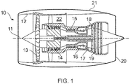
- a gas turbine engine 10 is shown in Figure 1 and comprises a principal and rotational axis 11.
- the engine 10 comprises, in axial flow series, an air intake 12, a propulsive fan 13, an intermediate pressure compressor 14, a high-pressure compressor 15, combustion equipment 16, a high-pressure turbine 17, an intermediate pressure turbine 18, a low-pressure turbine 19 and an exhaust nozzle 20.
- a nacelle 21 generally surrounds the engine 10 and defines both the intake 12 and the exhaust nozzle 20.
- a turbine case generally surrounds the high pressure turbine 17, intermediate pressure turbine 18 and low pressure turbine 19.
- the turbine case may be a single case extending axially around all three turbines 17, 18, 19 or individual turbine cases may be provided for each turbine 17, 18, 19.
- each manifold in use directing cooling air towards the turbine case.
- each manifold is provided with a circular duct which supplies the manifold with cooling air from the bypass duct.
- the circular ducts are typically arranged side-by-side.
- a cooling arrangement for a turbine casing of a gas turbine engine comprising a first cooling duct that is located within a second cooling duct, wherein the first cooling duct is for a first cooling fluid flow and wherein the second cooling duct is for a second cooling fluid flow which in use flows around the first cooling duct.
- the first cooling duct may be an inner duct and the second cooling duct may be an outer duct.
- the second duct may surround the inner duct.
- An inner flow passageway may be formed within the first duct.
- An outer flow passageway may be formed between the first and second ducts.
- the outer flow passageway may be annular.
- the outer flow passageway may completely surround the first duct.
- the first duct may be centrally located within the second duct.
- the first cooling duct and the second cooling duct may feed into a single manifold having outlet holes for directing cooling fluid towards the turbine casing.
- the first cooling duct and the second cooling duct may feed into separate manifolds, each manifold having outlet holes for directing cooling fluid towards the turbine casing.
- the first cooling duct may be enclosed by the second cooling duct along the majority or substantially all of its length.
- the first cooling duct may comprise a length portion that is not within or enclosed by the second cooling duct.
- the second cooling duct may be configured to allow the cooling fluid to flow therethrough substantially unmodulated.
- Electronic equipment and/or one or more cables may be mounted to the first cooling duct.
- the electronic equipment and/or the one or more cables may be mounted to an inner side and/or an outer side of the first cooling duct.
- the first cooling duct may comprise a valve, such as a butterfly valve, for controlling the flow of the first cooling fluid.
- the first cooling duct and/or the second cooling duct may have a substantially square or rectangular cross-section in a plane perpendicular to the longitudinal direction.
- the first cooling duct and/or the second cooling duct may comprise one or more substantially planar walls.
- the second cooling duct may be provided with a shielded tray on an outer surface thereof, the shielded tray being defined by a wall of the second cooling duct and one or more lips projecting from the cooling duct.
- Electronic equipment and/or one or more cables may be within the shielded tray.
- the first cooling duct may be mounted within the second cooling duct by at least one support element extending from one or more corners of the second cooling duct.
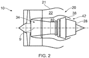
- the gas turbine engine 10 comprises a core engine 34 that includes the compressors, combustor, and turbines.
- the core engine 34 has the exhaust nozzle 28, sometimes referred to as the hot nozzle, at its axially downstream end at the exit of the high pressure turbine.
- Radially outside and spaced from the core engine 34 is the nacelle 21 which partially defines the bypass duct 22.
- a bypass exhaust nozzle 20 At the axially downstream end of the bypass duct 22 is a bypass exhaust nozzle 20, sometimes referred to as the cold nozzle.
- the radially inner extent of the bypass duct 22 is defined by an annular structure 38.
- the annular structure 38 may extend axially rearwards beyond the bypass exhaust nozzle 20.
- the annular space that is radially between the core engine 34 and the annular structure 38 defines a flow zone 40.
- the flow zone 40 comprises a flow zone nozzle 42 at its axially downstream end.
- the flow zone nozzle 42 is defined by the most axially rearward portion of the annular structure 38 and the radially outer surface of the exhaust nozzle 28.
- the flow zone 40 is configured for ingress of ventilation air bled from the bypass duct 32 which flows through the flow zone 40 and is expelled through the flow zone nozzle 42 in order to maintain a purge flow through the flow zone 40.
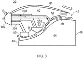
- Figure 3 shows an enlargement of part of a turbine assembly 44 of the gas turbine engine 10.
- the turbine assembly 44 has an inlet 46 and an outlet 48 at its axially upstream and downstream ends respectively.
- the turbine assembly 44 is radially enclosed by turbine casing 50.
- the turbine assembly 44 may comprise one, two or three turbine stages such as the high pressure turbine 17, intermediate pressure turbine 18 and low pressure turbine 19.
- the turbine casing 50 may be a single annular component that extends axially from the inlet 46 to the outlet 48 of the turbine assembly 44.
- the turbine casing 50 may be axially segmented so that there are two or more axial portions, for example one portion for each turbine stage 17, 18, 19.
- Such a segmented turbine casing 50 comprises suitable sealing between the axial portions to prevent egress of working fluid from the core engine 34 gas path into the flow zone 40.
- the gas turbine engine 10 is provided with a cooling arrangement (or system) for cooling the turbine casing 50.
- the cooling arrangement is configured to direct a cooling gas flow onto the turbine casing 50.
- the cooling assembly comprises a plurality of annular manifolds 52 that are radially outside the turbine casing 50 and spaced therefrom by a small distance. In this arrangement there are three manifolds, one for each turbine stage. In particular, each manifold 52 is axially aligned with a respective turbine stage 17, 18, 19.
- the manifolds 52 are arranged to provide cooling air to impingement cool a portion of the turbine casing 50 through impingement cooling holes provided in their radially inwardly directed surfaces.
- the cooling assembly further comprises a series of ducts 201, 203, 204 that supply cooling gas to the manifolds 52.
- the ducts 201 receive cooling air from the bypass duct 22 via a scoop 202 in the annular structure 38 (the radially inner wall of the bypass duct) which receives the bypass air flow.
- the cooling assembly comprises three ducts 201, 203, 204 (one for each manifold 52).
- a first manifold 52 is supplied with cooling gas from a single cooling duct 201, whilst second and third manifolds 52 are provided with cooling gas from a cooling duct assembly comprising a first inner cooling duct 203 and a second outer cooling duct 204.
- cooling air may be provided in any suitable or desired way, such as via an elevate (i.e. a higher pressure) source that is not from the bypass duct 22.
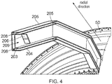
- the first inner cooling duct 203 is located within the second outer cooling duct 204 to form a "duct-in-duct" arrangement.
- the inner duct 203 is positioned centrally within the outer duct 204 so that an annular flow passage is defined between the inner and outer ducts 203, 204.
- first cooling air flows within the inner duct 203 whilst second cooling air flows in the annular passage between the inner and outer ducts 203, 204 and around the inner duct 203.
- the first and second cooling air flows remain separate.
- the inner duct 203 is located (or housed) within the outer duct 204 over the majority of its length.
- the inner and outer ducts 203, 204 are provided with cooling gas (air) from the scoop 202 and, as described above, supply the cooling air to separate manifolds 52. However, in some arrangements the inner and outer ducts 203, 204 may supply cooling gas to a common manifold 52. Locating one duct 203 within another duct 204 may minimise the space occupied by the first and second cooling ducts 203, 204.
- Each of the inner and outer cooling ducts 203, 204 has a square cross-sectional shape in a plane perpendicular to the longitudinal direction. As such, each duct 203, 204 is defined by four substantially planar walls. The ducts 203, 204 have a substantially uniform cross-section along their lengths. The inner duct 203 is centrally located within the outer duct 204 such that the ducts share a common central axis. In other arrangements the ducts 203, 204 could have a rectangular cross section, or a circular cross section, or any other suitable cross section. Further the inner and outer ducts may have different cross sections.
- the inner duct 203 is provided with a valve 204, which in this arrangement is a butterfly valve 206, for modulating (i.e. controlling) the flow 209 of cooling fluid in the first cooling duct 203.
- a valve 204 which in this arrangement is a butterfly valve 206, for modulating (i.e. controlling) the flow 209 of cooling fluid in the first cooling duct 203.
- the annular flow passageway defined between the inner and outer ducts 203, 204 is not provided with any valve and as such the cooling gas can flow therethrough unmodulated.
- the surface temperature of the inner duct 203 may be relatively low. Accordingly, it may be appropriate to attach electronic equipment and/or a cable (e.g. a cable harness) to a wall of the inner duct 204.
- a cable e.g. a cable harness
- the first inner cooling duct 203 is mounted within the second outer cooling duct 204 by support ribs 601 that extend from the internal corners of the outer cooling duct 204 to the external corners of the inner cooling duct 203. It will be appreciated that alternative means for mounting and supporting the inner duct 203 within the outer duct 204 could be used.
- FIG 6 shows an alternative duct-in-duct arrangement.
- the outer second cooling duct 204 is provided with a shielded tray for sensitive electronic equipment such as a cable harness 604 and/or electronic equipment.
- the tray is defined by a planar outer wall 205 of the second cooling duct 204 and first and second longitudinally extending lips 607 which project from the outer wall 205.
- the lips 607 may have the effect of at least reducing the radiative heating effect on the electronic equipment that is placed on the planar outer wall 205 (where the radiative heating originates from the turbine casing).
- the disclosure is not limited to an inner duct within an outer duct. In other arrangements multiple inner ducts could be located within an outer duct. Further, a third duct could be located within the inner duct.
Landscapes
- Engineering & Computer Science (AREA)
- Mechanical Engineering (AREA)
- General Engineering & Computer Science (AREA)
- Chemical & Material Sciences (AREA)
- Combustion & Propulsion (AREA)
- Turbine Rotor Nozzle Sealing (AREA)
Abstract
Description
- The present disclosure relates to a cooling arrangement for a turbine casing of a gas turbine engine.
- A
gas turbine engine 10 is shown inFigure 1 and comprises a principal androtational axis 11. Theengine 10 comprises, in axial flow series, anair intake 12, apropulsive fan 13, anintermediate pressure compressor 14, a high-pressure compressor 15,combustion equipment 16, a high-pressure turbine 17, anintermediate pressure turbine 18, a low-pressure turbine 19 and anexhaust nozzle 20. Anacelle 21 generally surrounds theengine 10 and defines both theintake 12 and theexhaust nozzle 20. - A turbine case generally surrounds the
high pressure turbine 17,intermediate pressure turbine 18 andlow pressure turbine 19. The turbine case may be a single case extending axially around all threeturbines turbine - It is typically necessary to selectively cool at least some of the turbine case during some engine running conditions in order to, e.g., reduce the clearance between the tips of the rotor blades of the turbine stage and the turbine case to improve engine performance.
- For this purpose it is known to provide a plurality of annular manifolds around the turbine case, each manifolds in use directing cooling air towards the turbine case. In a previously considered arrangement each manifold is provided with a circular duct which supplies the manifold with cooling air from the bypass duct. The circular ducts are typically arranged side-by-side.
- Whilst this arrangement may be satisfactory, it may be desirable to provide an improved cooling arrangement.
- According to an aspect there is provided a cooling arrangement for a turbine casing of a gas turbine engine, comprising a first cooling duct that is located within a second cooling duct, wherein the first cooling duct is for a first cooling fluid flow and wherein the second cooling duct is for a second cooling fluid flow which in use flows around the first cooling duct. The first cooling duct may be an inner duct and the second cooling duct may be an outer duct. The second duct may surround the inner duct. An inner flow passageway may be formed within the first duct. An outer flow passageway may be formed between the first and second ducts. The outer flow passageway may be annular. The outer flow passageway may completely surround the first duct. The first duct may be centrally located within the second duct.
- The first cooling duct and the second cooling duct may feed into a single manifold having outlet holes for directing cooling fluid towards the turbine casing. The first cooling duct and the second cooling duct may feed into separate manifolds, each manifold having outlet holes for directing cooling fluid towards the turbine casing.
- The first cooling duct may be enclosed by the second cooling duct along the majority or substantially all of its length. The first cooling duct may comprise a length portion that is not within or enclosed by the second cooling duct.
- The second cooling duct may be configured to allow the cooling fluid to flow therethrough substantially unmodulated.
- Electronic equipment and/or one or more cables may be mounted to the first cooling duct. The electronic equipment and/or the one or more cables may be mounted to an inner side and/or an outer side of the first cooling duct.
- The first cooling duct may comprise a valve, such as a butterfly valve, for controlling the flow of the first cooling fluid.
- The first cooling duct and/or the second cooling duct may have a substantially square or rectangular cross-section in a plane perpendicular to the longitudinal direction. The first cooling duct and/or the second cooling duct may comprise one or more substantially planar walls.
- The second cooling duct may be provided with a shielded tray on an outer surface thereof, the shielded tray being defined by a wall of the second cooling duct and one or more lips projecting from the cooling duct. Electronic equipment and/or one or more cables may be within the shielded tray.
- The first cooling duct may be mounted within the second cooling duct by at least one support element extending from one or more corners of the second cooling duct.
- There is also provided a gas turbine engine comprising a cooling arrangement in accordance with any statement herein.
- The skilled person will appreciate that except where mutually exclusive, a feature described in relation to any one of the above aspects may be applied mutatis mutandis to any other aspect. Furthermore except where mutually exclusive any feature described herein may be applied to any aspect and/or combined with any other feature described herein.
- Embodiments will now be described by way of example, with reference to the Figures, in which:
-
Figure 1 schematically shows a sectional side view of a gas turbine engine; -
Figure 2 schematically shows is a schematic side view of a gas turbine engine; -
Figure 3 schematically shows a part of a turbine cooling arrangement of the gas turbine engine ofFigure 2 ; -
Figure 4 schematically shows an enlarged sectional view of the ducts of the cooling arrangement ofFigure 3 ; -
Figure 5 schematically shows an enlarged view of the ducts of the cooling arrangement ofFigure 4 ; and -
Figure 6 schematically shows a further duct arrangement. - In all the Figures the general airflow direction is from left to right. Thus components drawn towards the left of any of the figures may be referred to as 'upstream' and those further towards the right of any of the figures may be referred to as 'downstream'.
- Referring to
Figure 2 thegas turbine engine 10 comprises acore engine 34 that includes the compressors, combustor, and turbines. Thecore engine 34 has theexhaust nozzle 28, sometimes referred to as the hot nozzle, at its axially downstream end at the exit of the high pressure turbine. Radially outside and spaced from thecore engine 34 is thenacelle 21 which partially defines thebypass duct 22. At the axially downstream end of thebypass duct 22 is abypass exhaust nozzle 20, sometimes referred to as the cold nozzle. The radially inner extent of thebypass duct 22 is defined by anannular structure 38. Theannular structure 38 may extend axially rearwards beyond thebypass exhaust nozzle 20. - The annular space that is radially between the
core engine 34 and theannular structure 38 defines aflow zone 40. Theflow zone 40 comprises aflow zone nozzle 42 at its axially downstream end. Theflow zone nozzle 42 is defined by the most axially rearward portion of theannular structure 38 and the radially outer surface of theexhaust nozzle 28. - The
flow zone 40 is configured for ingress of ventilation air bled from the bypass duct 32 which flows through theflow zone 40 and is expelled through theflow zone nozzle 42 in order to maintain a purge flow through theflow zone 40.Figure 3 shows an enlargement of part of aturbine assembly 44 of thegas turbine engine 10. Theturbine assembly 44 has aninlet 46 and anoutlet 48 at its axially upstream and downstream ends respectively. Theturbine assembly 44 is radially enclosed byturbine casing 50. Theturbine assembly 44 may comprise one, two or three turbine stages such as thehigh pressure turbine 17,intermediate pressure turbine 18 andlow pressure turbine 19. Theturbine casing 50 may be a single annular component that extends axially from theinlet 46 to theoutlet 48 of theturbine assembly 44. Alternatively, theturbine casing 50 may be axially segmented so that there are two or more axial portions, for example one portion for eachturbine stage turbine casing 50 comprises suitable sealing between the axial portions to prevent egress of working fluid from thecore engine 34 gas path into theflow zone 40. - The
gas turbine engine 10 is provided with a cooling arrangement (or system) for cooling theturbine casing 50. As will be described in detail below, the cooling arrangement is configured to direct a cooling gas flow onto theturbine casing 50. The cooling assembly comprises a plurality ofannular manifolds 52 that are radially outside theturbine casing 50 and spaced therefrom by a small distance. In this arrangement there are three manifolds, one for each turbine stage. In particular, each manifold 52 is axially aligned with arespective turbine stage manifolds 52 are arranged to provide cooling air to impingement cool a portion of theturbine casing 50 through impingement cooling holes provided in their radially inwardly directed surfaces. There may be an annular gap between pairs ofmanifolds 52 through which cooling air is expelled into theflow zone 40 after it impinges on theturbine casing 50. Some cooling air is entrained to flow downstream along theturbine casing 50 after impinging on a portion of theturbine casing 50. In an alternative arrangement a sealing structure may be provided betweenadjacent manifolds 52. - The cooling assembly further comprises a series of
ducts manifolds 52. Theducts 201 receive cooling air from thebypass duct 22 via ascoop 202 in the annular structure 38 (the radially inner wall of the bypass duct) which receives the bypass air flow. The cooling assembly comprises threeducts first manifold 52 is supplied with cooling gas from asingle cooling duct 201, whilst second andthird manifolds 52 are provided with cooling gas from a cooling duct assembly comprising a firstinner cooling duct 203 and a second outer coolingduct 204. - It will be appreciated that while the ducts have been described above as receiving cooling air from the
bypass duct 22 via ascoop 202 in theannular structure 38, this is not essential. The cooling air may be provided in any suitable or desired way, such as via an elevate (i.e. a higher pressure) source that is not from thebypass duct 22. - Referring now to
Figure 4 , the firstinner cooling duct 203 is located within the second outer coolingduct 204 to form a "duct-in-duct" arrangement. Theinner duct 203 is positioned centrally within theouter duct 204 so that an annular flow passage is defined between the inner andouter ducts inner duct 203 whilst second cooling air flows in the annular passage between the inner andouter ducts inner duct 203. The first and second cooling air flows remain separate. In this arrangement theinner duct 203 is located (or housed) within theouter duct 204 over the majority of its length. The inner andouter ducts scoop 202 and, as described above, supply the cooling air to separatemanifolds 52. However, in some arrangements the inner andouter ducts common manifold 52. Locating oneduct 203 within anotherduct 204 may minimise the space occupied by the first andsecond cooling ducts - Each of the inner and
outer cooling ducts duct ducts inner duct 203 is centrally located within theouter duct 204 such that the ducts share a common central axis. In other arrangements theducts - The
inner duct 203 is provided with avalve 204, which in this arrangement is abutterfly valve 206, for modulating (i.e. controlling) theflow 209 of cooling fluid in thefirst cooling duct 203. In this arrangement the annular flow passageway defined between the inner andouter ducts - Since cooling gas flows around the
inner duct 203 and within theinner duct 203, the surface temperature of theinner duct 203 may be relatively low. Accordingly, it may be appropriate to attach electronic equipment and/or a cable (e.g. a cable harness) to a wall of theinner duct 204. - As shown in
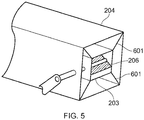
Figure 5 , the firstinner cooling duct 203 is mounted within the second outer coolingduct 204 bysupport ribs 601 that extend from the internal corners of theouter cooling duct 204 to the external corners of theinner cooling duct 203. It will be appreciated that alternative means for mounting and supporting theinner duct 203 within theouter duct 204 could be used. -
Figure 6 shows an alternative duct-in-duct arrangement. In this arrangement the outersecond cooling duct 204 is provided with a shielded tray for sensitive electronic equipment such as acable harness 604 and/or electronic equipment. In this arrangement the tray is defined by a planarouter wall 205 of thesecond cooling duct 204 and first and second longitudinally extendinglips 607 which project from theouter wall 205. Thelips 607 may have the effect of at least reducing the radiative heating effect on the electronic equipment that is placed on the planar outer wall 205 (where the radiative heating originates from the turbine casing). - It should be appreciated that the disclosure is not limited to an inner duct within an outer duct. In other arrangements multiple inner ducts could be located within an outer duct. Further, a third duct could be located within the inner duct.
- It will be understood that the technology described herein is not limited to the embodiments above-described and various modifications and improvements can be made without departing from the concepts described herein. Except where mutually exclusive, any of the features may be employed separately or in combination with any other features and the disclosure extends to and includes all combinations and sub-combinations of one or more features described herein.
Claims (14)
- A cooling arrangement for a turbine casing (50) of a gas turbine engine (10), comprising a first cooling duct (203) that is located within a second cooling duct (204), wherein the first cooling duct is for a first cooling fluid flow and wherein the second cooling duct is for a second cooling fluid flow which in use flows around the first cooling duct.
- A cooling arrangement as claimed in claim 1, wherein the first cooling duct (203) and the second cooling duct (204) feed into a single manifold (52) having outlet holes for directing cooling fluid towards the turbine casing.
- A cooling arrangement as claimed in claim 1, wherein the first cooling duct (203) and the second cooling duct (204) feed into separate manifolds (52), each manifold (52) having outlet holes for directing cooling fluid towards the turbine casing.
- A cooling arrangement as claimed in any preceding claim, wherein the first cooling duct (203) is enclosed by the second cooling duct (204) along the majority or substantially all of its length.
- A cooling arrangement as claimed in any preceding claim, wherein the second cooling duct (204) is configured to allow the cooling fluid to flow therethrough substantially unmodulated.
- A cooling arrangement as claimed in any preceding claim, wherein electronic equipment and/or one or more cables are mounted to the first cooling duct (203).
- A cooling arrangement as claimed in claim 6, wherein the electronic equipment and/or the one or more cables are mounted to an inner side and/or an outer side of the first cooling duct (203).
- A cooling arrangement as claimed in any preceding claim, wherein the first cooling duct (203) comprises a valve (206) for controlling the flow of the first cooling fluid.
- A cooling arrangement as claimed in any preceding claim, wherein the first cooling duct (203) and/or the second cooling duct (204) has a substantially square or rectangular cross-section in a plane perpendicular to the longitudinal direction.
- A cooling arrangement as claimed in any preceding claim, wherein the first cooling duct (203) and/or the second cooling duct (204) comprises one or more substantially planar walls (205).
- A cooling arrangement as claimed in any preceding claim, wherein the second cooling duct (204) is provided with a shielded tray on an outer surface thereof, the shielded tray being defined by a wall (205) of the second cooling duct and one or more lips projecting from the cooling duct (205).
- A cooling arrangement as claimed in claim 11, wherein electronic equipment and/or one or more cables are within the shielded tray.
- A cooling arrangement as claimed in any preceding claim, wherein the first cooling duct (203) is mounted within the second cooling duct (204) by at least one support element (601) extending from one or more corners of the second cooling duct (204).
- A gas turbine engine (10) comprising a cooling arrangement as claimed in any preceding claim.
Applications Claiming Priority (1)
| Application Number | Priority Date | Filing Date | Title |
|---|---|---|---|
| GBGB1718234.6A GB201718234D0 (en) | 2017-11-03 | 2017-11-03 | Cooling Arrangement for a turbine casing of a gas turbine engine |
Publications (2)
| Publication Number | Publication Date |
|---|---|
| EP3489467A2 true EP3489467A2 (en) | 2019-05-29 |
| EP3489467A3 EP3489467A3 (en) | 2019-08-14 |
Family
ID=60664936
Family Applications (1)
| Application Number | Title | Priority Date | Filing Date |
|---|---|---|---|
| EP18198411.3A Withdrawn EP3489467A3 (en) | 2017-11-03 | 2018-10-03 | Cooling arrangement for a turbine casing of a gas turbine engine |
Country Status (3)
| Country | Link |
|---|---|
| US (1) | US10794215B2 (en) |
| EP (1) | EP3489467A3 (en) |
| GB (1) | GB201718234D0 (en) |
Cited By (1)
| Publication number | Priority date | Publication date | Assignee | Title |
|---|---|---|---|---|
| GB2634529A (en) * | 2023-10-11 | 2025-04-16 | Rolls Royce Plc | System for cooling components associated with gas turbine engine |
Families Citing this family (3)
| Publication number | Priority date | Publication date | Assignee | Title |
|---|---|---|---|---|
| USD941360S1 (en) * | 2019-01-31 | 2022-01-18 | Elliott Company | Oval steam turbine casing |
| CN119604668A (en) * | 2022-08-09 | 2025-03-11 | 西门子能源国际公司 | Gas turbine engine with turbine blade carrier cooling flow path |
| US12116898B2 (en) * | 2023-01-26 | 2024-10-15 | Pratt & Whitney Canada Corp. | Ram air driven blade tip clearance control system for turboprop engines |
Family Cites Families (13)
| Publication number | Priority date | Publication date | Assignee | Title |
|---|---|---|---|---|
| US1023530A (en) * | 1910-10-14 | 1912-04-16 | Friedrich Schofer | Combined smoke and ventilation shaft. |
| US2475635A (en) * | 1945-01-08 | 1949-07-12 | Elmer C Parsons | Multiple conduit |
| GB1581566A (en) * | 1976-08-02 | 1980-12-17 | Gen Electric | Minimum clearance turbomachine shroud apparatus |
| DE3546839C2 (en) | 1985-11-19 | 1995-05-04 | Mtu Muenchen Gmbh | By-pass turbojet engine with split compressor |
| US8092153B2 (en) | 2008-12-16 | 2012-01-10 | Pratt & Whitney Canada Corp. | Bypass air scoop for gas turbine engine |
| DE102009010647A1 (en) | 2009-02-26 | 2010-09-02 | Rolls-Royce Deutschland Ltd & Co Kg | Running column adjustment system of an aircraft gas turbine |
| US8092146B2 (en) | 2009-03-26 | 2012-01-10 | Pratt & Whitney Canada Corp. | Active tip clearance control arrangement for gas turbine engine |
| US8668431B2 (en) * | 2010-03-29 | 2014-03-11 | United Technologies Corporation | Seal clearance control on non-cowled gas turbine engines |
| US8979477B2 (en) | 2011-03-09 | 2015-03-17 | General Electric Company | System for cooling and purging exhaust section of gas turbine engine |
| WO2014105522A1 (en) | 2012-12-29 | 2014-07-03 | United Technologies Corporation | Air stream mixing in inner diameter (id) cavity |
| EP2938859B1 (en) | 2012-12-29 | 2019-05-22 | United Technologies Corporation | Cooling architecture for turbine exhaust case |
| JP6223111B2 (en) | 2013-10-15 | 2017-11-01 | 三菱日立パワーシステムズ株式会社 | gas turbine |
| CN106255806B (en) | 2014-05-08 | 2019-05-31 | 西门子股份公司 | Turbine assembly and corresponding method of operation |
-
2017
- 2017-11-03 GB GBGB1718234.6A patent/GB201718234D0/en not_active Ceased
-
2018
- 2018-10-02 US US16/149,179 patent/US10794215B2/en active Active
- 2018-10-03 EP EP18198411.3A patent/EP3489467A3/en not_active Withdrawn
Cited By (1)
| Publication number | Priority date | Publication date | Assignee | Title |
|---|---|---|---|---|
| GB2634529A (en) * | 2023-10-11 | 2025-04-16 | Rolls Royce Plc | System for cooling components associated with gas turbine engine |
Also Published As
| Publication number | Publication date |
|---|---|
| US20190136713A1 (en) | 2019-05-09 |
| GB201718234D0 (en) | 2017-12-20 |
| US10794215B2 (en) | 2020-10-06 |
| EP3489467A3 (en) | 2019-08-14 |
Similar Documents
| Publication | Publication Date | Title |
|---|---|---|
| US7004720B2 (en) | Cooled turbine vane platform | |
| US12065946B2 (en) | Blade with tip rail cooling | |
| US10577944B2 (en) | Engine component with hollow turbulators | |
| CN107339125B (en) | System and method for cooling components of a gas turbine engine | |
| CN103597170B (en) | Case Cooling Duct | |
| US10519862B2 (en) | Gas turbine engine with rotor centering cooling system in an exhaust diffuser | |
| EP1388695B1 (en) | Cooling arrangement for brush seal | |
| US10753207B2 (en) | Airfoil with tip rail cooling | |
| CN1270066C (en) | Gas turbine and method for operating gas turbine | |
| US10544803B2 (en) | Method and system for cooling fluid distribution | |
| US20180320530A1 (en) | Airfoil with tip rail cooling | |
| US10794215B2 (en) | Cooling arrangement for a turbine casing of a gas turbine engine | |
| EP2963246A1 (en) | Turbine case cooling system | |
| US20190338651A1 (en) | Airfoil having cooling circuit | |
| US20170234137A1 (en) | Gas turbine engine trailing edge ejection holes | |
| US20180230812A1 (en) | Film hole arrangement for a turbine engine | |
| US10443407B2 (en) | Accelerator insert for a gas turbine engine airfoil | |
| US20180291752A1 (en) | Engine component with flow enhancer | |
| US10947859B2 (en) | Clearance control arrangement | |
| EP3118416B1 (en) | A gas turbine engine |
Legal Events
| Date | Code | Title | Description |
|---|---|---|---|
| PUAI | Public reference made under article 153(3) epc to a published international application that has entered the european phase |
Free format text: ORIGINAL CODE: 0009012 |
|
| STAA | Information on the status of an ep patent application or granted ep patent |
Free format text: STATUS: THE APPLICATION HAS BEEN PUBLISHED |
|
| AK | Designated contracting states |
Kind code of ref document: A2 Designated state(s): AL AT BE BG CH CY CZ DE DK EE ES FI FR GB GR HR HU IE IS IT LI LT LU LV MC MK MT NL NO PL PT RO RS SE SI SK SM TR |
|
| AX | Request for extension of the european patent |
Extension state: BA ME |
|
| PUAL | Search report despatched |
Free format text: ORIGINAL CODE: 0009013 |
|
| AK | Designated contracting states |
Kind code of ref document: A3 Designated state(s): AL AT BE BG CH CY CZ DE DK EE ES FI FR GB GR HR HU IE IS IT LI LT LU LV MC MK MT NL NO PL PT RO RS SE SI SK SM TR |
|
| AX | Request for extension of the european patent |
Extension state: BA ME |
|
| RIC1 | Information provided on ipc code assigned before grant |
Ipc: F02C 7/18 20060101ALI20190710BHEP Ipc: F01D 25/26 20060101ALI20190710BHEP Ipc: F01D 11/24 20060101AFI20190710BHEP Ipc: F01D 25/14 20060101ALI20190710BHEP |
|
| RAP1 | Party data changed (applicant data changed or rights of an application transferred) |
Owner name: ROLLS-ROYCE PLC |
|
| STAA | Information on the status of an ep patent application or granted ep patent |
Free format text: STATUS: THE APPLICATION IS DEEMED TO BE WITHDRAWN |
|
| 18D | Application deemed to be withdrawn |
Effective date: 20200215 |