EP3489116A1 - Rope hook structure for bumper part of walking work machine - Google Patents
Rope hook structure for bumper part of walking work machine Download PDFInfo
- Publication number
- EP3489116A1 EP3489116A1 EP17834165.7A EP17834165A EP3489116A1 EP 3489116 A1 EP3489116 A1 EP 3489116A1 EP 17834165 A EP17834165 A EP 17834165A EP 3489116 A1 EP3489116 A1 EP 3489116A1
- Authority
- EP
- European Patent Office
- Prior art keywords
- rope
- bumper
- support part
- mooring
- walking
- Prior art date
- Legal status (The legal status is an assumption and is not a legal conclusion. Google has not performed a legal analysis and makes no representation as to the accuracy of the status listed.)
- Withdrawn
Links
- 239000003921 oil Substances 0.000 description 9
- 230000005540 biological transmission Effects 0.000 description 7
- 238000000034 method Methods 0.000 description 6
- 239000000945 filler Substances 0.000 description 5
- 239000010705 motor oil Substances 0.000 description 5
- 238000007689 inspection Methods 0.000 description 3
- 238000004804 winding Methods 0.000 description 3
- 230000000694 effects Effects 0.000 description 2
- 239000000446 fuel Substances 0.000 description 2
- 239000002828 fuel tank Substances 0.000 description 2
- 239000002699 waste material Substances 0.000 description 2
- 230000003247 decreasing effect Effects 0.000 description 1
- 230000000717 retained effect Effects 0.000 description 1
- XLYOFNOQVPJJNP-UHFFFAOYSA-N water Substances O XLYOFNOQVPJJNP-UHFFFAOYSA-N 0.000 description 1
Images




Classifications
-
- A—HUMAN NECESSITIES
- A01—AGRICULTURE; FORESTRY; ANIMAL HUSBANDRY; HUNTING; TRAPPING; FISHING
- A01B—SOIL WORKING IN AGRICULTURE OR FORESTRY; PARTS, DETAILS, OR ACCESSORIES OF AGRICULTURAL MACHINES OR IMPLEMENTS, IN GENERAL
- A01B33/00—Tilling implements with rotary driven tools, e.g. in combination with fertiliser distributors or seeders, with grubbing chains, with sloping axles, with driven discs
- A01B33/02—Tilling implements with rotary driven tools, e.g. in combination with fertiliser distributors or seeders, with grubbing chains, with sloping axles, with driven discs with tools on horizontal shaft transverse to direction of travel
- A01B33/028—Tilling implements with rotary driven tools, e.g. in combination with fertiliser distributors or seeders, with grubbing chains, with sloping axles, with driven discs with tools on horizontal shaft transverse to direction of travel of the walk-behind type
-
- B—PERFORMING OPERATIONS; TRANSPORTING
- B60—VEHICLES IN GENERAL
- B60R—VEHICLES, VEHICLE FITTINGS, OR VEHICLE PARTS, NOT OTHERWISE PROVIDED FOR
- B60R19/00—Wheel guards; Radiator guards, e.g. grilles; Obstruction removers; Fittings damping bouncing force in collisions
- B60R19/02—Bumpers, i.e. impact receiving or absorbing members for protecting vehicles or fending off blows from other vehicles or objects
- B60R19/48—Bumpers, i.e. impact receiving or absorbing members for protecting vehicles or fending off blows from other vehicles or objects combined with, or convertible into, other devices or objects, e.g. bumpers combined with road brushes, bumpers convertible into beds
-
- A—HUMAN NECESSITIES
- A01—AGRICULTURE; FORESTRY; ANIMAL HUSBANDRY; HUNTING; TRAPPING; FISHING
- A01B—SOIL WORKING IN AGRICULTURE OR FORESTRY; PARTS, DETAILS, OR ACCESSORIES OF AGRICULTURAL MACHINES OR IMPLEMENTS, IN GENERAL
- A01B33/00—Tilling implements with rotary driven tools, e.g. in combination with fertiliser distributors or seeders, with grubbing chains, with sloping axles, with driven discs
- A01B33/08—Tools; Details, e.g. adaptations of transmissions or gearings
-
- A—HUMAN NECESSITIES
- A01—AGRICULTURE; FORESTRY; ANIMAL HUSBANDRY; HUNTING; TRAPPING; FISHING
- A01B—SOIL WORKING IN AGRICULTURE OR FORESTRY; PARTS, DETAILS, OR ACCESSORIES OF AGRICULTURAL MACHINES OR IMPLEMENTS, IN GENERAL
- A01B73/00—Means or arrangements to facilitate transportation of agricultural machines or implements, e.g. folding frames to reduce overall width
-
- B—PERFORMING OPERATIONS; TRANSPORTING
- B60—VEHICLES IN GENERAL
- B60R—VEHICLES, VEHICLE FITTINGS, OR VEHICLE PARTS, NOT OTHERWISE PROVIDED FOR
- B60R19/00—Wheel guards; Radiator guards, e.g. grilles; Obstruction removers; Fittings damping bouncing force in collisions
- B60R19/02—Bumpers, i.e. impact receiving or absorbing members for protecting vehicles or fending off blows from other vehicles or objects
-
- B—PERFORMING OPERATIONS; TRANSPORTING
- B62—LAND VEHICLES FOR TRAVELLING OTHERWISE THAN ON RAILS
- B62D—MOTOR VEHICLES; TRAILERS
- B62D51/00—Motor vehicles characterised by the driver not being seated
- B62D51/04—Motor vehicles characterised by the driver not being seated the driver walking
- B62D51/06—Uniaxle walk-type tractors
Definitions
- the present invention relates to a rope hook structure for a bumper disposed in a front end portion of a walking-type work machine, which is used to fix the walking-type work machine with rope when the walking-type work machine is placed on a vehicular platform.
- a walking-type work machine When a walking-type work machine is placed on a platform of a truck or the like to be transported, the walking-type work machine is typically fixed to the platform with rope.
- a rope hook is provided in a front end portion of a walking-type work machine to facilitate rope hanging in such situations.
- a projecting part is formed upward from a lateral center of an upper edge portion of a balance weight and a rope hanging opening with a lateral width that is smaller than that of a grip opening is formed in the projecting part (see e.g., Patent Literature 1, hereinafter referred to as PTL1).
- a bumper is provided so as to project further forward than a machine body and front rope hooks are provided in an upper front portion of the bumper (see e.g., Patent Literature 2, hereinafter referred to as PTL2).
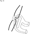
- the rope hanging opening is provided centrally in a front portion of the balance weight and thus, as illustrated in FIG. 13 , the walking-type work machine is fixed to a platform of a truck by retaining one end of rope on a hook on the right or left side of the platform of the truck, threading the other end of the rope through the rope hanging opening, and then hanging the rope on the hook on the aforementioned right or left side of the platform to tighten the rope, and similarly on the other of the right and left sides, by threading rope into the rope hanging opening and fastening the rope on a hook.
- the rope threading into the rope hanging opening needs to be performed at least twice, which requires two ropes or a long rope and requires that the rope or ropes be fastened on both of the right and left sides.
- the fixing is a troublesome operation.
- pulling the rope or ropes from the rope hanging opening is necessary, which causes the rope or ropes to be intertwined easily and constitutes another troublesome operation.
- a walking-type work machine includes a machine body and a bumper provided in a front end portion of the machine body, the bumper including: a support part with a front portion that abuts on a mooring portion; and a rope hook on which rope is hung for mooring, the support part being configured to be pressed to the mooring portion by tensile force that is exerted by the rope being hung and fastened for the mooring on the rope hook and on a retaining hook that is provided in the mooring portion.
- a grip part is provided in an upper front portion of the bumper and the rope hook is provided adjacent to the grip part.
- the rope hook is provided on each of right and left sides of the grip part.
- the rope hook includes an upward projection and a rearward projection
- the support part includes a lower support part corresponding to the upward projection and a front support part corresponding to the rearward projection.
- the present invention brings advantageous effects described below.
- a bumper includes a support part and rope hooks. Accordingly, when rope is hung and fastened on the rope hooks and on retaining hooks provided in a mooring portion, the bumper is fixed to the mooring portion while the mooring portion abuts on the support part. Thus, compared to a conventional structure where only a rope hanging opening or a rope hook is pulled for tightening, shifting is hindered and firm fixing is enabled. In addition, when the rope is tightened, the tightening load can be prevented from placing burden on an axle, a wheel, or a tilling unit of the walking-type work machine, and damage can be avoided even if tightening with excessive force is performed.
- Embodiments of a managing machine 1 as a walking-type work machine including a bumper 20 according to the present invention are described below. The description is given, assuming that direction F serves as the forward direction.
- the managing machine 1 includes an engine 3 installed over a machine body frame 2, and a transmission case 4 is provided to stand in a laterally (i.e., left-right direction) central portion of the machine body frame 2 and behind the engine 3.
- a power transmission case 5 is arranged between an upper portion of the transmission case 4 and the engine 3 so that power can be transmitted.
- a tilling shaft 6 is laid below the transmission case 4 horizontally from side to side. That is, the tilling shaft 6 is provided to be orthogonal to the direction F, which serves as the traveling direction. Tilling tines 7 are fixed to the tilling shaft 6 radially at predetermined intervals. In this manner, a tilling device 10 is constituted.
- a base of handles 8 is fixedly provided above the transmission case 4 that makes up a machine body rear portion.
- the handles 8 are provided to project obliquely rearward and upward.
- a grip is provided in a rear portion of each handle 8 so that an operator can grasp the grips.
- Clutch levers, accelerator levers, and so on are arranged near the grips.
- a fuel tank is arranged above the engine 3.
- a hood 9 covers the engine 3 and the fuel tank.
- a resistance rod 11 is attached to a rear portion of the machine body frame 2 so as to be vertically adjustable in height.
- the bumper 20 according to the present invention is attached to a front end of the machine body frame 2.
- the bumper 20 according to the present invention is described in detail below with reference to FIGs. 1 to 7 .
- the bumper 20 is shaped like an approximately oval ring in a front view and a plan view, which includes: attachment base parts 21 on both sides in a lower rear portion; and attachment holes 22 formed above the attachment base parts 21 to penetrate in the fore-and-aft (front-rear) direction.
- the bumper 20 is fixed to the machine body frame 2 by bolts inserted into the attachment holes 22 from the front or the rear. At this time, rear surfaces of the attachment base parts 21 abut on a front end surface of the machine body frame 2.
- a rear surface between the attachment base parts 21 forms a depression 23 so that when the bumper 20 is attached to the machine body frame 2, space is created between the bumper 20 and a front surface of the engine 3 as illustrated in FIG. 3 .
- a drain bolt 12 which is provided on a lower front surface of a crankcase of the engine 3 can be detached. This enables waste oil to be removed.
- a tool is inserted from below the depression 23 to loosen and detach the drain bolt 12 so that the waste oil is discharged from the space.
- An inspection filler cap 13 is provided obliquely above the drain bolt 12. After the drain bolt 12 is tightened, the inspection filler cap 13 that covers an oil filler inlet 13a ( FIG. 8 ) is detached, so that a predetermined amount of engine oil can be supplied from the oil filler inlet 13a.
- Side column parts 24 are provided to extend obliquely upward and forward from the attachment base parts 21.
- a grip part 25 connects upper portions of the right and left column parts 24.
- the attachment base parts 21, the side column parts 24, and the grip part 25 form a ring-like shape with a grasping opening 26 formed at the center, to make it easy to grasp the grip part 25 in a case of, for example, lifting up the managing machine 1.
- the grasping opening 26 enables the drain bolt 12 to be visually identified therethrough from the front at a time of oil change for example. Space is created between the grip part 25 and the front surface of the engine 3 such that the drain bolt 12 and the inspection filler cap 13 can be operated easily.
- Drain depressions 27 are formed on the rear surfaces at locations outer than the attachment base parts 21. Sloping grooves 28 that lead to the drain depressions 27 and that extend obliquely vertically (i.e., up-down direction) are formed on rear surfaces of the side column parts 24. Thus, when the bumper 20 is attached to the machine body frame 2, drain holes are formed between the drain depressions 27 and a front surface of the machine body frame 2. Accordingly, rain that falls on rear portions of the side column parts 24 or engine oil that spills at a time of oil supply flows in the sloping grooves 28 to be discharged from the drain holes that the drain depressions 27 form such that no water or oil can accumulate in a rear lower portion of the bumper 20.
- the grip part 25 has a thickness that allows a grasp by a human hand and is positioned in a vertically intermediate portion of the managing machine 1 to project furthest forward and protect the engine 3. Sufficient space that causes no hindrance for a grasp on the grip part 25 is formed between the grip part 25 and the front surface of the engine 3. The grip part 25 forms part of the ring-like grasping opening 26 and is thus made so that no release can happen even if a slip occurs during a movement with the grip part 25 grasped for example.
- Rope hooks 30 are formed next to the grip part 25 of the bumper 20 and on rear portions of the grip part 25 on both of the right and left sides. Each of the rope hooks 30 projects from a rear portion of the grip part 25 and from an upper rear portion of the side column part 24. Each of the rope hooks 30 includes an upward projection 31 and a rearward projection 32. The upward projections 31 are formed to project further upward than an upper surface of the grip part 25 and each have a size that allows rope to be hung thereat. Each of the rearward projections 32 is formed obliquely downward and rearward relative to the upward projection 31, and is continuous with the upward projection 31. The rearward projections 32 project rearward from upper rear surfaces of the side column parts 24, and each have a size that allows rope to be hung.
- the rope 40 can be hung on the upward projections 31 and the rearward projections 32 by being wound once without being threaded into any hole.
- the rope hooks 30 may be formed to be integral with a front weight attached to the bumper 20 or a front end of the machine body frame 2 or with a front weight that also functions as the bumper 20.
- the bumper 20 includes a support part 14 that surface-abuts on a platform in order that the managing machine 1 that is placed on a platform of a truck or the like for transportation can be easily and firmly fixed to the platform by fastening with the rope 40, even for different types of platforms such as a platform of a truck and a platform of a carrier vehicle. That is, lower support parts 14a are disposed in a lower front portion of the bumper 20 so as to correspond to the upward projections 31 and a front support part 14b is disposed in an upper front portion of the bumper 20 so as to correspond to the rearward projections 32.
- the bumper 20 includes the lower support parts 14a and the front support part 14b, and in a side view, the lower support part 14a is positioned below the upward projection 31 and the front support part 14b is positioned further forward than the rearward projection 32. That is, the lower support part 14a and the upward projection 31 are positioned opposite to each other in the vertical direction while the front support part 14b and the rearward projection 32 are positioned opposite to each other in the fore-and-aft direction.
- the lower support parts 14a are positioned further forward than the attachment base parts 21 and includes an abutting surface with an approximately right angle in a side view.
- the front support part 14b is positioned above and further forward than the lower support parts 14a, serves as a front surface of the grip part 25, is vertical, and forms an abutting surface in the lateral direction.
- the lower support parts 14a and the front support part 14b are arranged so as to be capable of abutting on a gate of a platform of a truck or a carrier vehicle.
- a gate surrounds a platform of a truck and retaining hooks are provided on the outer side of an upper portion of the gate at predetermined intervals in a longitudinal direction.
- retaining hooks 52 are provided in a lower portion of a gate 51 disposed to surround a platform 50 of a light truck and retaining hooks 62 are provided in a lower portion of a gate 61 for a platform 60 of a standard-sized truck.
- the managing machine 1 When placed and fixed on the platform 50 (60), the managing machine 1 is fixed to the gate 51 (61), which is a rearward mooring portion of the bumper 20, by causing the managing machine 1 to face rearward before placing the managing machine 1 on the platform 50 (60).
- heights are set so that when the managing machine 1 including the bumper 20 according to the present invention is placed on the platform 50 of the light truck, the lower support parts 14a are positioned at an upper end of the gate 51 of the light truck and when the managing machine is placed on the platform 60 of the standard-sized truck, the front support parts 14b abut on an upper inside surface of the gate 61.
- the gate 61 of the platform 60 of the standard-sized truck is higher than the gate 51 of the light truck.
- the fixing is performed by causing the lower support parts 14a to abut on an upper-end front corner portion of the gate 51, retaining one end of the rope 40 on the retaining hook 52 on one of the right and left sides, winding the other end of the rope 40 on the rope hooks 30, and then tying and fastening the rope 40 on the retaining hook 52 on the other of the right and left sides.
- the rope 40 is tightened in this fixing, the rope 40 pulls the upward projections 31 downward and pulls the retaining hooks 52 upward.
- the gate 51 and the lower support parts 14a of the bumper 20 are brought into close surface-contact in two positions to be tied tightly with the rope 40, and the bumper 20 can be firmly fixed to the gate 51 accordingly. Since the rope 40 is wound on the rope hooks 30 at two positions, shifting in the lateral direction can be hindered.
- the managing machine 1 can be fixed in an approximately horizontal position and thus, leakage of fuel, transmission oil, or engine oil can be inhibited.
- the fixing is performed by causing the front support part 14b to abut on an upper front surface of the gate 61, retaining one end of the rope 40 on the retaining hook 62 on one of the right and left sides, winding the other end of the rope 40 on the rope hooks 30, and then tying and fastening the rope 40 on the retaining hook 62 on the other of the right and left sides.
- the managing machine 1 can avoid rotating about the tilling shaft 6 forward or rearward. Further, the rope hooks 30 on the right and left sides are retained and fastened with respect to the retaining hooks 52 (62) positioned at further toward the sides and accordingly, shifting in the lateral direction can be hindered. In addition, the managing machine 1 can be fixed in an approximately horizontal position and thus, leakage of fuel, transmission oil, or engine oil can be inhibited.
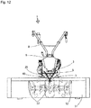
- the tying may be performed with the retaining hook 52 (62) positioned between the rope hooks 30 as illustrated in FIG. 12 .
- the retaining hook 52 (62) positioned between the rope hooks 30 as illustrated in FIG. 12 .
- supporting and fixing at three points are possible while omitting the necessity of pulling the rope laterally outward.
- This allows the rope 40 to be shortened in order to achieve firm fixing.
- the tying can be performed without requiring a long-distance movement from side to side. That is, time needed for rope hanging can be reduced.
- the managing machine 1 as a walking-type work machine includes a machine body and the bumper 20 provided in a front end portion of the machine body, the bumper 20 including: the support part 14, which abuts on the gate 51 (61) with a front portion that serves as a mooring portion; and the rope hooks 30 on which the rope 40 may be hung for mooring, the support part 14 being configured to be pressed to the mooring portion by tensile force that is exerted by the rope 40 being hung and fastened for the mooring on the rope hooks 30 and on the retaining hooks 52 (62) provided in the mooring portion.
- the rope hooks 30 are positioned in the machine body front portion of the managing machine 1 at a time of placement on a platform of a truck or the like, and the fixing can be performed easily and reliably. Further, the rope 40 is tightened for the fixing while the support part 14 is in abutment with the gate 51 (61). Thus, burden that the tightening load places on an axle, a wheel, a tilling device, or the like can be reduced, and damage can be avoided even if the tightening is performed with excessive force. Once the rope 40 is tightened and fixed, the managing machine 1 can hardly shift. Thus, the managing machine 1 can be transported in a stable state by a truck or the like.
- the bumper 20 includes, in its upper front portion, the grip part 25.
- the rope hooks 30 are provided adjacent to the grip part 25. Since an operator grasps the grip part 25 of the bumper 20 when placing the managing machine 1 onto a truck, the operator can easily recognize the rope hooks 30 provided adjacent to the grip part 25 and avoid becoming confused in hanging the rope 40.
- the rope hooks 30 are provided on both of the right and left sides of the grip part 25, the rope 40 is hung and wound at two positions. This makes the rope 40 less likely to loosen, and thus lateral shifting can be prevented. Further, the rope hanging on the rope hooks 30 involves no necessity of threading the rope 40 into respective holes. Instead, the rope 40 is wound from one side to the other side of the right and left sides to be hung on both of the rope hooks 30, and tied fixedly on the other side. Thus, as illustrated in FIG. 13 , hanging and fastening the rope both rightward and leftward is unnecessary and the length of the rope 40 can be decreased while facilitating the rope hanging and reducing the operation time.
- the rope hook 30 includes the upward projection 31 and the rearward projection 32.
- the support part 14 includes the lower support part 14a corresponding to the upward projection 31 and the front support part 14b corresponding to the rearward projection 32. Accordingly, when the rope 40 is hung on the rope hooks 30 and pulled, the following occurs. In a case of the gate 51 of the truck which is low, the lower support parts 14a is brought into abutment with the upper portion of the gate 51 so that the tensile force of the rope 40 acts on the upward projections 31 and pulls the rope 40 rearward.
- the front support part 14b is brought into abutment with an inner surface of the gate 61 so that the tensile force of the rope 40 acts on the rearward projections 32 and pulls the rope 40 in the fore-and-aft direction (rearward in the present embodiment).
- reliable fixing can be achieved by pulling the rope 40 in the vertical direction or the fore-and-aft direction without displacing the rope 40 in any of the directions.
- the present invention is applicable to a walking-type work machine including a traveling machine body and a bumper provided in a front end of the traveling machine body, such as a walking-type managing machine that performs tilling, ridging, and so on in paddies and fields, a walking-type transplant machine, and a walking-type mowing machine.
Landscapes
- Engineering & Computer Science (AREA)
- Mechanical Engineering (AREA)
- Life Sciences & Earth Sciences (AREA)
- Soil Sciences (AREA)
- Environmental Sciences (AREA)
- Chemical & Material Sciences (AREA)
- Combustion & Propulsion (AREA)
- Transportation (AREA)
- Body Structure For Vehicles (AREA)
- Soil Working Implements (AREA)
Abstract
Description
- The present invention relates to a rope hook structure for a bumper disposed in a front end portion of a walking-type work machine, which is used to fix the walking-type work machine with rope when the walking-type work machine is placed on a vehicular platform.
- When a walking-type work machine is placed on a platform of a truck or the like to be transported, the walking-type work machine is typically fixed to the platform with rope. Techniques are known in which a rope hook is provided in a front end portion of a walking-type work machine to facilitate rope hanging in such situations. In a known technique, for example, a projecting part is formed upward from a lateral center of an upper edge portion of a balance weight and a rope hanging opening with a lateral width that is smaller than that of a grip opening is formed in the projecting part (see e.g.,
Patent Literature 1, hereinafter referred to as PTL1). - In another known technique, a bumper is provided so as to project further forward than a machine body and front rope hooks are provided in an upper front portion of the bumper (see e.g.,
Patent Literature 2, hereinafter referred to as PTL2). -
- PTL1: Japanese Patent Application Laid-Open No.
2012-196169 - PTL2: Japanese Patent Application Laid-Open No.
2015-53901 - In the technique of PTL1, however, the rope hanging opening is provided centrally in a front portion of the balance weight and thus, as illustrated in
FIG. 13 , the walking-type work machine is fixed to a platform of a truck by retaining one end of rope on a hook on the right or left side of the platform of the truck, threading the other end of the rope through the rope hanging opening, and then hanging the rope on the hook on the aforementioned right or left side of the platform to tighten the rope, and similarly on the other of the right and left sides, by threading rope into the rope hanging opening and fastening the rope on a hook. Accordingly, the rope threading into the rope hanging opening needs to be performed at least twice, which requires two ropes or a long rope and requires that the rope or ropes be fastened on both of the right and left sides. As a result, the fixing is a troublesome operation. Also in rope removal, pulling the rope or ropes from the rope hanging opening is necessary, which causes the rope or ropes to be intertwined easily and constitutes another troublesome operation. - In the structure according to the technique of PTL2, two U-shaped hooks are formed in an upper front portion of the bumper to be opened laterally inward. Accordingly, to fix the walking-type work machine to a platform with rope, it is necessary to hang rope on the right and left hooks and then pull and tighten the rope outward in both of the right and left directions. This requires two ropes or a long rope. Moreover, in the tightening, it is necessary to move to left and right of the platform to hang and fix the rope or ropes. Thus, it takes time for the fixing. Further, in the technique of PTL2, since the bumper is formed to be bent with a pipe and extend obliquely upward and forward, the platform of the truck and the bumper are in point or line abutment with each other. Thus, when movement occurs while the bumper is fixed with rope, the abutting portion may slide easily. This involves a risk that the abutting position may be displaced to loosen the rope.
- It is therefore attempted to provide a rope hook structure for a walking-type work machine, which can facilitate rope hanging and achieve reliable fixing to a platform of a truck or the like.
- The problems that the present invention attempts to solve are described above and means for solving the problems are described below.
- That is, in an aspect of the present invention, a walking-type work machine includes a machine body and a bumper provided in a front end portion of the machine body, the bumper including: a support part with a front portion that abuts on a mooring portion; and a rope hook on which rope is hung for mooring, the support part being configured to be pressed to the mooring portion by tensile force that is exerted by the rope being hung and fastened for the mooring on the rope hook and on a retaining hook that is provided in the mooring portion.
- In the aspect of the present invention, a grip part is provided in an upper front portion of the bumper and the rope hook is provided adjacent to the grip part.
- In the aspect of the present invention, the rope hook is provided on each of right and left sides of the grip part.
- In the aspect of the present invention, the rope hook includes an upward projection and a rearward projection, and the support part includes a lower support part corresponding to the upward projection and a front support part corresponding to the rearward projection.
- The present invention brings advantageous effects described below.
- That is, a bumper includes a support part and rope hooks. Accordingly, when rope is hung and fastened on the rope hooks and on retaining hooks provided in a mooring portion, the bumper is fixed to the mooring portion while the mooring portion abuts on the support part. Thus, compared to a conventional structure where only a rope hanging opening or a rope hook is pulled for tightening, shifting is hindered and firm fixing is enabled. In addition, when the rope is tightened, the tightening load can be prevented from placing burden on an axle, a wheel, or a tilling unit of the walking-type work machine, and damage can be avoided even if tightening with excessive force is performed.
-
- [
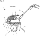
FIG. 1 ] An overall side view of a managing machine including a bumper according to the present invention. - [
FIG. 2 ] A front view of the managing machine. - [
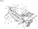
FIG. 3 ] A perspective view of an attachment portion of the bumper. - [
FIG. 4 ] A perspective view of the bumper. - [
FIG. 5 ] A side view of the bumper. - [
FIG. 6 ] A front view of the bumper. - [
FIG. 7 ] A plan view of the bumper. - [
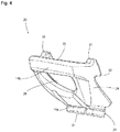
FIG. 8 ] A side view illustrating a state where the bumper is tightly fixed to a gate of a light truck with rope. - [
FIG. 9 ] A plan view illustrating the state inFIG. 8 . - [
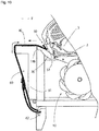
FIG. 10 ] A side view illustrating a state where the bumper is tightly fixed to a gate of a standard-sized truck with rope. - [
FIG. 11 ] A plan view illustrating the state inFIG. 10 . - [
FIG. 12 ] A rear view illustrating another embodiment of rope hanging. - [
FIG. 13 ] A perspective view illustrating a state where rope is hung through a rope hanging opening formed in a conventional front weight. - Embodiments of a managing
machine 1 as a walking-type work machine including abumper 20 according to the present invention are described below. The description is given, assuming that direction F serves as the forward direction. - As in
FIGs. 1 and2 , the managingmachine 1 includes anengine 3 installed over amachine body frame 2, and atransmission case 4 is provided to stand in a laterally (i.e., left-right direction) central portion of themachine body frame 2 and behind theengine 3. Apower transmission case 5 is arranged between an upper portion of thetransmission case 4 and theengine 3 so that power can be transmitted. Atilling shaft 6 is laid below thetransmission case 4 horizontally from side to side. That is, thetilling shaft 6 is provided to be orthogonal to the direction F, which serves as the traveling direction.Tilling tines 7 are fixed to thetilling shaft 6 radially at predetermined intervals. In this manner, atilling device 10 is constituted. - A base of
handles 8 is fixedly provided above thetransmission case 4 that makes up a machine body rear portion. Thehandles 8 are provided to project obliquely rearward and upward. A grip is provided in a rear portion of eachhandle 8 so that an operator can grasp the grips. Clutch levers, accelerator levers, and so on are arranged near the grips. A fuel tank is arranged above theengine 3. Ahood 9 covers theengine 3 and the fuel tank. Further, aresistance rod 11 is attached to a rear portion of themachine body frame 2 so as to be vertically adjustable in height. Thebumper 20 according to the present invention is attached to a front end of themachine body frame 2. - The
bumper 20 according to the present invention is described in detail below with reference toFIGs. 1 to 7 . - As illustrated in
FIGs. 6 and7 , thebumper 20 is shaped like an approximately oval ring in a front view and a plan view, which includes:attachment base parts 21 on both sides in a lower rear portion; and attachment holes 22 formed above theattachment base parts 21 to penetrate in the fore-and-aft (front-rear) direction. Thebumper 20 is fixed to themachine body frame 2 by bolts inserted into the attachment holes 22 from the front or the rear. At this time, rear surfaces of theattachment base parts 21 abut on a front end surface of themachine body frame 2. - As illustrated in
FIG. 7 , a rear surface between theattachment base parts 21 forms adepression 23 so that when thebumper 20 is attached to themachine body frame 2, space is created between thebumper 20 and a front surface of theengine 3 as illustrated inFIG. 3 . Due to the space, adrain bolt 12 which is provided on a lower front surface of a crankcase of theengine 3 can be detached. This enables waste oil to be removed. To change engine oil, a tool is inserted from below thedepression 23 to loosen and detach thedrain bolt 12 so that the waste oil is discharged from the space. Aninspection filler cap 13 is provided obliquely above thedrain bolt 12. After thedrain bolt 12 is tightened, theinspection filler cap 13 that covers anoil filler inlet 13a (FIG. 8 ) is detached, so that a predetermined amount of engine oil can be supplied from theoil filler inlet 13a. -
Side column parts 24 are provided to extend obliquely upward and forward from theattachment base parts 21. Agrip part 25 connects upper portions of the right and leftcolumn parts 24. Thus, theattachment base parts 21, theside column parts 24, and thegrip part 25 form a ring-like shape with a graspingopening 26 formed at the center, to make it easy to grasp thegrip part 25 in a case of, for example, lifting up the managingmachine 1. The graspingopening 26 enables thedrain bolt 12 to be visually identified therethrough from the front at a time of oil change for example. Space is created between thegrip part 25 and the front surface of theengine 3 such that thedrain bolt 12 and theinspection filler cap 13 can be operated easily. -
Drain depressions 27 are formed on the rear surfaces at locations outer than theattachment base parts 21. Slopinggrooves 28 that lead to thedrain depressions 27 and that extend obliquely vertically (i.e., up-down direction) are formed on rear surfaces of theside column parts 24. Thus, when thebumper 20 is attached to themachine body frame 2, drain holes are formed between thedrain depressions 27 and a front surface of themachine body frame 2. Accordingly, rain that falls on rear portions of theside column parts 24 or engine oil that spills at a time of oil supply flows in thesloping grooves 28 to be discharged from the drain holes that thedrain depressions 27 form such that no water or oil can accumulate in a rear lower portion of thebumper 20. - The
grip part 25 has a thickness that allows a grasp by a human hand and is positioned in a vertically intermediate portion of the managingmachine 1 to project furthest forward and protect theengine 3. Sufficient space that causes no hindrance for a grasp on thegrip part 25 is formed between thegrip part 25 and the front surface of theengine 3. Thegrip part 25 forms part of the ring-like graspingopening 26 and is thus made so that no release can happen even if a slip occurs during a movement with thegrip part 25 grasped for example. - Rope hooks 30 are formed next to the
grip part 25 of thebumper 20 and on rear portions of thegrip part 25 on both of the right and left sides. Each of the rope hooks 30 projects from a rear portion of thegrip part 25 and from an upper rear portion of theside column part 24. Each of the rope hooks 30 includes anupward projection 31 and arearward projection 32. Theupward projections 31 are formed to project further upward than an upper surface of thegrip part 25 and each have a size that allows rope to be hung thereat. Each of therearward projections 32 is formed obliquely downward and rearward relative to theupward projection 31, and is continuous with theupward projection 31. Therearward projections 32 project rearward from upper rear surfaces of theside column parts 24, and each have a size that allows rope to be hung. Accordingly, therope 40 can be hung on theupward projections 31 and therearward projections 32 by being wound once without being threaded into any hole. The rope hooks 30 may be formed to be integral with a front weight attached to thebumper 20 or a front end of themachine body frame 2 or with a front weight that also functions as thebumper 20. - Further, the
bumper 20 includes asupport part 14 that surface-abuts on a platform in order that the managingmachine 1 that is placed on a platform of a truck or the like for transportation can be easily and firmly fixed to the platform by fastening with therope 40, even for different types of platforms such as a platform of a truck and a platform of a carrier vehicle. That is,lower support parts 14a are disposed in a lower front portion of thebumper 20 so as to correspond to theupward projections 31 and afront support part 14b is disposed in an upper front portion of thebumper 20 so as to correspond to therearward projections 32. In other words, thebumper 20 includes thelower support parts 14a and thefront support part 14b, and in a side view, thelower support part 14a is positioned below theupward projection 31 and thefront support part 14b is positioned further forward than therearward projection 32. That is, thelower support part 14a and theupward projection 31 are positioned opposite to each other in the vertical direction while thefront support part 14b and therearward projection 32 are positioned opposite to each other in the fore-and-aft direction. Thelower support parts 14a are positioned further forward than theattachment base parts 21 and includes an abutting surface with an approximately right angle in a side view. Thefront support part 14b is positioned above and further forward than thelower support parts 14a, serves as a front surface of thegrip part 25, is vertical, and forms an abutting surface in the lateral direction. - The
lower support parts 14a and thefront support part 14b are arranged so as to be capable of abutting on a gate of a platform of a truck or a carrier vehicle. Normally, a gate surrounds a platform of a truck and retaining hooks are provided on the outer side of an upper portion of the gate at predetermined intervals in a longitudinal direction. For example, retaining hooks 52 are provided in a lower portion of agate 51 disposed to surround aplatform 50 of a light truck and retaininghooks 62 are provided in a lower portion of agate 61 for aplatform 60 of a standard-sized truck. - When placed and fixed on the platform 50 (60), the managing
machine 1 is fixed to the gate 51 (61), which is a rearward mooring portion of thebumper 20, by causing the managingmachine 1 to face rearward before placing the managingmachine 1 on the platform 50 (60). In the present embodiment, heights are set so that when the managingmachine 1 including thebumper 20 according to the present invention is placed on theplatform 50 of the light truck, thelower support parts 14a are positioned at an upper end of thegate 51 of the light truck and when the managing machine is placed on theplatform 60 of the standard-sized truck, thefront support parts 14b abut on an upper inside surface of thegate 61. Thegate 61 of theplatform 60 of the standard-sized truck is higher than thegate 51 of the light truck. - When the managing
machine 1 is placed in a rear portion of theplatform 50 of the light truck to be tied and fixed thereto with therope 40, as illustrated inFIGs. 8 and9 , the fixing is performed by causing thelower support parts 14a to abut on an upper-end front corner portion of thegate 51, retaining one end of therope 40 on the retaininghook 52 on one of the right and left sides, winding the other end of therope 40 on the rope hooks 30, and then tying and fastening therope 40 on the retaininghook 52 on the other of the right and left sides. When therope 40 is tightened in this fixing, therope 40 pulls theupward projections 31 downward and pulls the retaining hooks 52 upward. Thus, thegate 51 and thelower support parts 14a of thebumper 20 are brought into close surface-contact in two positions to be tied tightly with therope 40, and thebumper 20 can be firmly fixed to thegate 51 accordingly. Since therope 40 is wound on the rope hooks 30 at two positions, shifting in the lateral direction can be hindered. In addition, the managingmachine 1 can be fixed in an approximately horizontal position and thus, leakage of fuel, transmission oil, or engine oil can be inhibited. - When the managing
machine 1 is placed in a rear portion of theplatform 60 of the standard-sized truck to be tied and fixed thereto with therope 40, as illustrated inFIGs. 10 and11 , the fixing is performed by causing thefront support part 14b to abut on an upper front surface of thegate 61, retaining one end of therope 40 on the retaininghook 62 on one of the right and left sides, winding the other end of therope 40 on the rope hooks 30, and then tying and fastening therope 40 on the retaininghook 62 on the other of the right and left sides. When therope 40 is tightened in this fixing, therearward projections 32 are pulled rearward and the retaining hooks 62 are pulled upward, and an inner surface (front surface) of thegate 61 and a surface of thefront support part 14b of thebumper 20 come into close contact and tied tightly with therope 40 to be firmly fixed. As a result of the winding on the rope hooks 30 at two positions, shifting in the lateral direction can be hindered and the managingmachine 1 can be prevented from moving on theplatform 60. - Since the gate 51 (61) and the
bumper 20 abut on each other at their surfaces and fixed in this manner, the managingmachine 1 can avoid rotating about the tillingshaft 6 forward or rearward. Further, the rope hooks 30 on the right and left sides are retained and fastened with respect to the retaining hooks 52 (62) positioned at further toward the sides and accordingly, shifting in the lateral direction can be hindered. In addition, the managingmachine 1 can be fixed in an approximately horizontal position and thus, leakage of fuel, transmission oil, or engine oil can be inhibited. - When the
bumper 20 is tied to the gate 51 (61) with rope, the tying may be performed with the retaining hook 52 (62) positioned between the rope hooks 30 as illustrated inFIG. 12 . In this case, supporting and fixing at three points are possible while omitting the necessity of pulling the rope laterally outward. This allows therope 40 to be shortened in order to achieve firm fixing. Thus, the tying can be performed without requiring a long-distance movement from side to side. That is, time needed for rope hanging can be reduced. - As described above, the managing
machine 1 as a walking-type work machine includes a machine body and thebumper 20 provided in a front end portion of the machine body, thebumper 20 including: thesupport part 14, which abuts on the gate 51 (61) with a front portion that serves as a mooring portion; and the rope hooks 30 on which therope 40 may be hung for mooring, thesupport part 14 being configured to be pressed to the mooring portion by tensile force that is exerted by therope 40 being hung and fastened for the mooring on the rope hooks 30 and on the retaining hooks 52 (62) provided in the mooring portion. Accordingly, the rope hooks 30 are positioned in the machine body front portion of the managingmachine 1 at a time of placement on a platform of a truck or the like, and the fixing can be performed easily and reliably. Further, therope 40 is tightened for the fixing while thesupport part 14 is in abutment with the gate 51 (61). Thus, burden that the tightening load places on an axle, a wheel, a tilling device, or the like can be reduced, and damage can be avoided even if the tightening is performed with excessive force. Once therope 40 is tightened and fixed, the managingmachine 1 can hardly shift. Thus, the managingmachine 1 can be transported in a stable state by a truck or the like. - The
bumper 20 includes, in its upper front portion, thegrip part 25. The rope hooks 30 are provided adjacent to thegrip part 25. Since an operator grasps thegrip part 25 of thebumper 20 when placing the managingmachine 1 onto a truck, the operator can easily recognize the rope hooks 30 provided adjacent to thegrip part 25 and avoid becoming confused in hanging therope 40. - Since the rope hooks 30 are provided on both of the right and left sides of the
grip part 25, therope 40 is hung and wound at two positions. This makes therope 40 less likely to loosen, and thus lateral shifting can be prevented. Further, the rope hanging on the rope hooks 30 involves no necessity of threading therope 40 into respective holes. Instead, therope 40 is wound from one side to the other side of the right and left sides to be hung on both of the rope hooks 30, and tied fixedly on the other side. Thus, as illustrated inFIG. 13 , hanging and fastening the rope both rightward and leftward is unnecessary and the length of therope 40 can be decreased while facilitating the rope hanging and reducing the operation time. - The
rope hook 30 includes theupward projection 31 and therearward projection 32. Thesupport part 14 includes thelower support part 14a corresponding to theupward projection 31 and thefront support part 14b corresponding to therearward projection 32. Accordingly, when therope 40 is hung on the rope hooks 30 and pulled, the following occurs. In a case of thegate 51 of the truck which is low, thelower support parts 14a is brought into abutment with the upper portion of thegate 51 so that the tensile force of therope 40 acts on theupward projections 31 and pulls therope 40 rearward. In a case of thegate 61 which is high, thefront support part 14b is brought into abutment with an inner surface of thegate 61 so that the tensile force of therope 40 acts on therearward projections 32 and pulls therope 40 in the fore-and-aft direction (rearward in the present embodiment). As described above, with various heights of the gate, reliable fixing can be achieved by pulling therope 40 in the vertical direction or the fore-and-aft direction without displacing therope 40 in any of the directions. - The present invention is applicable to a walking-type work machine including a traveling machine body and a bumper provided in a front end of the traveling machine body, such as a walking-type managing machine that performs tilling, ridging, and so on in paddies and fields, a walking-type transplant machine, and a walking-type mowing machine.
-
- 2
- machine body frame
- 14
- support part
- 14a
- lower support part
- 14b
- front support part
- 20
- bumper
- 25
- grip part
- 30
- rope hook
- 31
- upward projection
- 32
- rearward projection
- 40
- rope
- 51,61
- gate
Claims (4)
- A bumper-unit rope hook structure for a walking-type work machine including a machine body and a bumper provided in a front end portion of the machine body, the bumper including: a support part with a front portion that abuts on a mooring portion; and a rope hook on which rope is hung for mooring, the support part being configured to be pressed to the mooring portion by tensile force that is exerted by the rope being hung and fastened for the mooring on the rope hook and on a retaining hook that is provided in the mooring portion.
- The bumper-unit rope hook structure for the walking-type work machine according to claim 1, wherein
a grip part is provided in an upper front portion of the bumper and the rope hook is provided adjacent to the grip part. - The bumper-unit rope hook structure for the walking-type work machine according to claim 1 or 2, wherein
the rope hook is provided on each of right and left sides of the grip part. - The bumper-unit rope hook structure for the walking-type work machine according to any one of claims 1 to 3, wherein
the rope hook includes an upward projection and a rearward projection, and
the support part includes a lower support part corresponding to the upward projection and a front support part corresponding to the rearward projection.
Applications Claiming Priority (2)
| Application Number | Priority Date | Filing Date | Title |
|---|---|---|---|
| JP2016145576A JP6671761B2 (en) | 2016-07-25 | 2016-07-25 | Rope hook structure for bumper section of walking type working machine |
| PCT/JP2017/026367 WO2018021157A1 (en) | 2016-07-25 | 2017-07-20 | Rope hook structure for bumper part of walking work machine |
Publications (2)
| Publication Number | Publication Date |
|---|---|
| EP3489116A1 true EP3489116A1 (en) | 2019-05-29 |
| EP3489116A4 EP3489116A4 (en) | 2019-08-28 |
Family
ID=61016107
Family Applications (1)
| Application Number | Title | Priority Date | Filing Date |
|---|---|---|---|
| EP17834165.7A Withdrawn EP3489116A4 (en) | 2016-07-25 | 2017-07-20 | Rope hook structure for bumper part of walking work machine |
Country Status (4)
| Country | Link |
|---|---|
| EP (1) | EP3489116A4 (en) |
| JP (1) | JP6671761B2 (en) |
| KR (1) | KR102099032B1 (en) |
| WO (1) | WO2018021157A1 (en) |
Families Citing this family (2)
| Publication number | Priority date | Publication date | Assignee | Title |
|---|---|---|---|---|
| JP6827375B2 (en) * | 2017-06-27 | 2021-02-10 | 株式会社クボタ | Balance weight |
| JP7362517B2 (en) * | 2020-03-05 | 2023-10-17 | 株式会社クボタ | Counterweights for work vehicles and work vehicles |
Family Cites Families (5)
| Publication number | Priority date | Publication date | Assignee | Title |
|---|---|---|---|---|
| JPH0415587Y2 (en) * | 1986-05-02 | 1992-04-08 | ||
| JP3188425B2 (en) * | 1999-03-08 | 2001-07-16 | 株式会社マルナカ製作所 | Set dynamic injection |
| JP4512552B2 (en) * | 2005-12-20 | 2010-07-28 | 三菱農機株式会社 | Mobile farm machine |
| JP2012196169A (en) | 2011-03-22 | 2012-10-18 | Mitsubishi Agricultural Machinery Co Ltd | Balance weight structure of walking-type movable farm machine |
| JP5973974B2 (en) | 2013-09-12 | 2016-08-23 | 株式会社クボタ | Seedling transplanter |
-
2016
- 2016-07-25 JP JP2016145576A patent/JP6671761B2/en active Active
-
2017
- 2017-07-20 KR KR1020187029836A patent/KR102099032B1/en active Active
- 2017-07-20 EP EP17834165.7A patent/EP3489116A4/en not_active Withdrawn
- 2017-07-20 WO PCT/JP2017/026367 patent/WO2018021157A1/en not_active Ceased
Also Published As
| Publication number | Publication date |
|---|---|
| EP3489116A4 (en) | 2019-08-28 |
| JP6671761B2 (en) | 2020-03-25 |
| KR102099032B1 (en) | 2020-04-08 |
| WO2018021157A1 (en) | 2018-02-01 |
| JP2018016111A (en) | 2018-02-01 |
| KR20180123543A (en) | 2018-11-16 |
Similar Documents
| Publication | Publication Date | Title |
|---|---|---|
| US6969049B2 (en) | Device for mounting on a vehicle for hoisting and transporting a big-game carcass | |
| US9546082B2 (en) | Fork truck boom apparatus | |
| KR102099032B1 (en) | Rope hook structure of the bumper part of the walking machine | |
| US20160114721A1 (en) | Work vehicle and rotating light | |
| KR20100002308U (en) | Safety fall prevention device for low gas station | |
| US7537423B1 (en) | Chain tiedown for transportation vehicle | |
| KR101865366B1 (en) | Device for opening and closing manhole cover | |
| WO2011126380A1 (en) | Guide device for a strap and method of using same | |
| US9284716B2 (en) | Work vehicle | |
| JP6827375B2 (en) | Balance weight | |
| KR20130024337A (en) | Chain sling storage device | |
| US10544011B2 (en) | Hoisting frame for overweight lifting | |
| US20140110647A1 (en) | Interchangeable transmission cradle attachment for lift jack | |
| KR101438503B1 (en) | Cable hanger | |
| CN212306120U (en) | transplanter | |
| JP3117639U (en) | Y-type cable roller for wire drawing | |
| CN212125220U (en) | Double-handle flat car with good safety | |
| JP2014103760A (en) | Tool bag hanger | |
| KR100415231B1 (en) | Apparatus for fixing a load for vehicles | |
| JP2004147556A (en) | Riding rice transplanter | |
| GB2470627A (en) | Method of stowing a boat fender and apparatus therefor | |
| JP3012472U (en) | Rope boost tightening fixture | |
| JP2026010301A (en) | Bolt removal protection | |
| JP4341956B2 (en) | Hanging bracket | |
| FR3039473A1 (en) | PLATFORM, BENCH OR OTHER DEVICE HAVING A PLATFORM FOR FIXING, INTENDED TO BE INSTALLED ON SMALL LIGHTENING UTILITY VEHICLES IN ORDER TO CHANGE FREQUENTLY |
Legal Events
| Date | Code | Title | Description |
|---|---|---|---|
| STAA | Information on the status of an ep patent application or granted ep patent |
Free format text: STATUS: THE INTERNATIONAL PUBLICATION HAS BEEN MADE |
|
| PUAI | Public reference made under article 153(3) epc to a published international application that has entered the european phase |
Free format text: ORIGINAL CODE: 0009012 |
|
| STAA | Information on the status of an ep patent application or granted ep patent |
Free format text: STATUS: REQUEST FOR EXAMINATION WAS MADE |
|
| 17P | Request for examination filed |
Effective date: 20190221 |
|
| AK | Designated contracting states |
Kind code of ref document: A1 Designated state(s): AL AT BE BG CH CY CZ DE DK EE ES FI FR GB GR HR HU IE IS IT LI LT LU LV MC MK MT NL NO PL PT RO RS SE SI SK SM TR |
|
| AX | Request for extension of the european patent |
Extension state: BA ME |
|
| A4 | Supplementary search report drawn up and despatched |
Effective date: 20190729 |
|
| RIC1 | Information provided on ipc code assigned before grant |
Ipc: B60R 19/02 20060101ALI20190723BHEP Ipc: A01B 33/08 20060101ALI20190723BHEP Ipc: B60R 19/48 20060101ALI20190723BHEP Ipc: B62D 51/06 20060101AFI20190723BHEP |
|
| DAV | Request for validation of the european patent (deleted) | ||
| DAX | Request for extension of the european patent (deleted) | ||
| RAP1 | Party data changed (applicant data changed or rights of an application transferred) |
Owner name: YANMAR POWER TECHNOLOGY CO., LTD. |
|
| GRAP | Despatch of communication of intention to grant a patent |
Free format text: ORIGINAL CODE: EPIDOSNIGR1 |
|
| STAA | Information on the status of an ep patent application or granted ep patent |
Free format text: STATUS: GRANT OF PATENT IS INTENDED |
|
| INTG | Intention to grant announced |
Effective date: 20210205 |
|
| STAA | Information on the status of an ep patent application or granted ep patent |
Free format text: STATUS: THE APPLICATION IS DEEMED TO BE WITHDRAWN |
|
| 18D | Application deemed to be withdrawn |
Effective date: 20210616 |