EP3489088B1 - Apparatus and method for controlling side mirror system for vehicle - Google Patents
Apparatus and method for controlling side mirror system for vehicle Download PDFInfo
- Publication number
- EP3489088B1 EP3489088B1 EP18207768.5A EP18207768A EP3489088B1 EP 3489088 B1 EP3489088 B1 EP 3489088B1 EP 18207768 A EP18207768 A EP 18207768A EP 3489088 B1 EP3489088 B1 EP 3489088B1
- Authority
- EP
- European Patent Office
- Prior art keywords
- vehicle
- side mirror
- mirror
- electronic side
- display panel
- Prior art date
- Legal status (The legal status is an assumption and is not a legal conclusion. Google has not performed a legal analysis and makes no representation as to the accuracy of the status listed.)
- Active
Links
Images








Classifications
-
- B—PERFORMING OPERATIONS; TRANSPORTING
- B60—VEHICLES IN GENERAL
- B60R—VEHICLES, VEHICLE FITTINGS, OR VEHICLE PARTS, NOT OTHERWISE PROVIDED FOR
- B60R1/00—Optical viewing arrangements; Real-time viewing arrangements for drivers or passengers using optical image capturing systems, e.g. cameras or video systems specially adapted for use in or on vehicles
- B60R1/20—Real-time viewing arrangements for drivers or passengers using optical image capturing systems, e.g. cameras or video systems specially adapted for use in or on vehicles
- B60R1/22—Real-time viewing arrangements for drivers or passengers using optical image capturing systems, e.g. cameras or video systems specially adapted for use in or on vehicles for viewing an area outside the vehicle, e.g. the exterior of the vehicle
- B60R1/23—Real-time viewing arrangements for drivers or passengers using optical image capturing systems, e.g. cameras or video systems specially adapted for use in or on vehicles for viewing an area outside the vehicle, e.g. the exterior of the vehicle with a predetermined field of view
- B60R1/26—Real-time viewing arrangements for drivers or passengers using optical image capturing systems, e.g. cameras or video systems specially adapted for use in or on vehicles for viewing an area outside the vehicle, e.g. the exterior of the vehicle with a predetermined field of view to the rear of the vehicle
-
- B—PERFORMING OPERATIONS; TRANSPORTING
- B60—VEHICLES IN GENERAL
- B60R—VEHICLES, VEHICLE FITTINGS, OR VEHICLE PARTS, NOT OTHERWISE PROVIDED FOR
- B60R1/00—Optical viewing arrangements; Real-time viewing arrangements for drivers or passengers using optical image capturing systems, e.g. cameras or video systems specially adapted for use in or on vehicles
- B60R1/02—Rear-view mirror arrangements
- B60R1/04—Rear-view mirror arrangements mounted inside vehicle
-
- B—PERFORMING OPERATIONS; TRANSPORTING
- B60—VEHICLES IN GENERAL
- B60R—VEHICLES, VEHICLE FITTINGS, OR VEHICLE PARTS, NOT OTHERWISE PROVIDED FOR
- B60R1/00—Optical viewing arrangements; Real-time viewing arrangements for drivers or passengers using optical image capturing systems, e.g. cameras or video systems specially adapted for use in or on vehicles
- B60R1/02—Rear-view mirror arrangements
- B60R1/06—Rear-view mirror arrangements mounted on vehicle exterior
- B60R1/0602—Rear-view mirror arrangements mounted on vehicle exterior comprising means for cleaning or deicing
-
- B—PERFORMING OPERATIONS; TRANSPORTING
- B60—VEHICLES IN GENERAL
- B60R—VEHICLES, VEHICLE FITTINGS, OR VEHICLE PARTS, NOT OTHERWISE PROVIDED FOR
- B60R1/00—Optical viewing arrangements; Real-time viewing arrangements for drivers or passengers using optical image capturing systems, e.g. cameras or video systems specially adapted for use in or on vehicles
- B60R1/02—Rear-view mirror arrangements
- B60R1/06—Rear-view mirror arrangements mounted on vehicle exterior
- B60R1/062—Rear-view mirror arrangements mounted on vehicle exterior with remote control for adjusting position
-
- B—PERFORMING OPERATIONS; TRANSPORTING
- B60—VEHICLES IN GENERAL
- B60R—VEHICLES, VEHICLE FITTINGS, OR VEHICLE PARTS, NOT OTHERWISE PROVIDED FOR
- B60R1/00—Optical viewing arrangements; Real-time viewing arrangements for drivers or passengers using optical image capturing systems, e.g. cameras or video systems specially adapted for use in or on vehicles
- B60R1/02—Rear-view mirror arrangements
- B60R1/06—Rear-view mirror arrangements mounted on vehicle exterior
- B60R1/062—Rear-view mirror arrangements mounted on vehicle exterior with remote control for adjusting position
- B60R1/07—Rear-view mirror arrangements mounted on vehicle exterior with remote control for adjusting position by electrically powered actuators
- B60R1/074—Rear-view mirror arrangements mounted on vehicle exterior with remote control for adjusting position by electrically powered actuators for retracting the mirror arrangements to a non-use position alongside the vehicle
-
- B—PERFORMING OPERATIONS; TRANSPORTING
- B60—VEHICLES IN GENERAL
- B60R—VEHICLES, VEHICLE FITTINGS, OR VEHICLE PARTS, NOT OTHERWISE PROVIDED FOR
- B60R1/00—Optical viewing arrangements; Real-time viewing arrangements for drivers or passengers using optical image capturing systems, e.g. cameras or video systems specially adapted for use in or on vehicles
- B60R1/02—Rear-view mirror arrangements
- B60R1/08—Rear-view mirror arrangements involving special optical features, e.g. avoiding blind spots, e.g. convex mirrors; Side-by-side associations of rear-view and other mirrors
-
- B—PERFORMING OPERATIONS; TRANSPORTING
- B60—VEHICLES IN GENERAL
- B60R—VEHICLES, VEHICLE FITTINGS, OR VEHICLE PARTS, NOT OTHERWISE PROVIDED FOR
- B60R1/00—Optical viewing arrangements; Real-time viewing arrangements for drivers or passengers using optical image capturing systems, e.g. cameras or video systems specially adapted for use in or on vehicles
- B60R1/12—Mirror assemblies combined with other articles, e.g. clocks
-
- B—PERFORMING OPERATIONS; TRANSPORTING
- B60—VEHICLES IN GENERAL
- B60S—SERVICING, CLEANING, REPAIRING, SUPPORTING, LIFTING, OR MANOEUVRING OF VEHICLES, NOT OTHERWISE PROVIDED FOR
- B60S1/00—Cleaning of vehicles
- B60S1/02—Cleaning windscreens, windows or optical devices
-
- G—PHYSICS
- G02—OPTICS
- G02B—OPTICAL ELEMENTS, SYSTEMS OR APPARATUS
- G02B27/00—Optical systems or apparatus not provided for by any of the groups G02B1/00 - G02B26/00, G02B30/00
- G02B27/0006—Optical systems or apparatus not provided for by any of the groups G02B1/00 - G02B26/00, G02B30/00 with means to keep optical surfaces clean, e.g. by preventing or removing dirt, stains, contamination, condensation
-
- B—PERFORMING OPERATIONS; TRANSPORTING
- B60—VEHICLES IN GENERAL
- B60R—VEHICLES, VEHICLE FITTINGS, OR VEHICLE PARTS, NOT OTHERWISE PROVIDED FOR
- B60R1/00—Optical viewing arrangements; Real-time viewing arrangements for drivers or passengers using optical image capturing systems, e.g. cameras or video systems specially adapted for use in or on vehicles
- B60R1/12—Mirror assemblies combined with other articles, e.g. clocks
- B60R2001/1215—Mirror assemblies combined with other articles, e.g. clocks with information displays
-
- B—PERFORMING OPERATIONS; TRANSPORTING
- B60—VEHICLES IN GENERAL
- B60R—VEHICLES, VEHICLE FITTINGS, OR VEHICLE PARTS, NOT OTHERWISE PROVIDED FOR
- B60R1/00—Optical viewing arrangements; Real-time viewing arrangements for drivers or passengers using optical image capturing systems, e.g. cameras or video systems specially adapted for use in or on vehicles
- B60R1/12—Mirror assemblies combined with other articles, e.g. clocks
- B60R2001/1223—Mirror assemblies combined with other articles, e.g. clocks with sensors or transducers
-
- B—PERFORMING OPERATIONS; TRANSPORTING
- B60—VEHICLES IN GENERAL
- B60R—VEHICLES, VEHICLE FITTINGS, OR VEHICLE PARTS, NOT OTHERWISE PROVIDED FOR
- B60R1/00—Optical viewing arrangements; Real-time viewing arrangements for drivers or passengers using optical image capturing systems, e.g. cameras or video systems specially adapted for use in or on vehicles
- B60R1/12—Mirror assemblies combined with other articles, e.g. clocks
- B60R2001/1253—Mirror assemblies combined with other articles, e.g. clocks with cameras, video cameras or video screens
-
- B—PERFORMING OPERATIONS; TRANSPORTING
- B60—VEHICLES IN GENERAL
- B60R—VEHICLES, VEHICLE FITTINGS, OR VEHICLE PARTS, NOT OTHERWISE PROVIDED FOR
- B60R2300/00—Details of viewing arrangements using cameras and displays, specially adapted for use in a vehicle
- B60R2300/80—Details of viewing arrangements using cameras and displays, specially adapted for use in a vehicle characterised by the intended use of the viewing arrangement
- B60R2300/802—Details of viewing arrangements using cameras and displays, specially adapted for use in a vehicle characterised by the intended use of the viewing arrangement for monitoring and displaying vehicle exterior blind spot views
- B60R2300/8026—Details of viewing arrangements using cameras and displays, specially adapted for use in a vehicle characterised by the intended use of the viewing arrangement for monitoring and displaying vehicle exterior blind spot views in addition to a rear-view mirror system
Definitions
- the disclosure relates to an apparatus and a method for controlling a side mirror system for a vehicle. More particularly, the disclosure relates to a method of moving an electronic side mirror to the inside of the vehicle under a specified condition, while an electronic side mirror is disposed outside a vehicle.
- the vehicle may include side mirrors in the right side and the left side of the vehicle.
- a driver may verify the peripheral area of the vehicle by using light reflected from optical mirrors of the side mirrors.
- the vehicle may include an electronic side mirror (E side mirror) instead of a side mirror including an optical mirror.
- the electronic side mirror may include a display.
- the display may output an image, which is obtained by a camera module mounted in the vehicle and which is associated with the peripheral area of the vehicle.
- the camera module may obtain the image of a range wider than the optical mirror.
- JP2010116125 concerns a driver support device that includes a monitor for displaying an image of the vehicle rear side; a moving part for moving at least one part of the monitor between an inside and an outside of the vehicle; and a mirror supported by the at least one part of the monitor moved to the outside of the vehicle by the moving part, and for confirming visually the vehicle rear side in the inside of the vehicle.
- an electronic side mirror a location where an electronic side mirror is disposed may be discussed.
- the electronic side mirror When the electronic side mirror is interposed between a driver's seat and a passenger's seat as a center information display (CID) or is disposed on a dashboard or in a rear-view mirror, the electronic side mirror may violate regulations of European Union (EU) and the driver of the vehicle may feel inconvenience because the driver needs to verify a peripheral area of the vehicle in a direction different from the existing direction.
- EU European Union
- the driver's view may not be secured.
- the electronic side mirror When the electronic side mirror is disposed on a cluster, the driver's eyes may be fatigued due to an image always output by a display.
- the electronic side mirror When the electronic side mirror is disposed at a location the same as the side mirror of the related art, the driver may feel inconvenience to verify the peripheral area of the vehicle in a weather state of poor visibility.
- the vehicle may not output the image obtained through a camera module, to the driver of the vehicle.
- an aspect of the disclosure is to provide a method of moving an electronic side mirror to the inside of the vehicle under a specified condition, while an electronic side mirror is disposed outside a vehicle.
- Another aspect of the disclosure is to provide a method in which an electronic side mirror operates in a mirror mode when a display of the electronic side mirror does not operate normally.
- a side mirror system for a vehicle according to claim 1 and a method of operating a side mirror system for a vehicle according to claim 11 is provided.
- a side mirror system for a vehicle may include an electronic side mirror disposed outside the vehicle, thereby preventing a driver from feeling inconvenience or fatigue without violating regulations of EU.
- a side mirror system for a vehicle may control a moving device such that an electronic side mirror moves to the inside or the outside of the vehicle, and thus may provide an environment in which a driver is capable of verifying the peripheral area of the vehicle even in bad weather.
- a side mirror system for a vehicle may control an electronic side mirror so as to perform the function of an optical mirror, and thus may provide a driver with a backup environment when a display does not operate normally.
- FIG. 1 illustrates a vehicle including a side mirror system for a vehicle according to various embodiments of the disclosure.
- a vehicle 1 may include a side mirror system 100 for a vehicle used to verify the peripheral area of the vehicle 1.
- the side mirror system 100 for a vehicle may include a camera module 110 (or, a camera 110), a moving unit 120, an electronic side mirror 130, at least one control circuit 140, and a sensor module 150.
- the vehicle 1 may not include a part of components illustrated in FIG. 1 or may further include a new component.
- the vehicle 1 may not include the sensor module 150 and may include an input device that receives a user input.
- the vehicle 1 may further include a removing unit that removes rainwater or a foreign object from the front surface of the electronic side mirror 130.
- the camera module 110 may obtain an image associated with the peripheral area of the vehicle 1.
- the camera module 110 may be disposed outside the vehicle 1.
- the left camera module may be disposed on the left side of an A-pillar 20a
- the right camera module may be disposed on the right side of an A-pillar 20b.
- each of the left camera module and the right camera module may be disposed in the body (e.g., doors 30a and 30b) of the vehicle 1.
- the camera module 110 may include at least one lens assembly capable of collecting light emitted from a subject, a flash capable of emitting a light source used to strengthen light emitted from the subject, an image sensor capable of converting light transmitted from the subject through the lens assembly into an electrical signal, an image stabilizer capable of at least partly compensating (e.g., adjust read-out timing) for negative effects (e.g., image blurring) caused by the movement of the camera module 110 or the vehicle 1, a memory capable of temporarily storing at least part of the image obtained through the image sensor, or an image signal processor capable of performing processing (e.g., noise reduction, resolution adjustment, brightness adjustment, blurring, sharpening, or softening) on an image obtained through the image sensor or an image stored in the memory.
- the image signal processor may not be included in the camera module 110, and may be included in the at least one control circuit 140.
- the electronic side mirror 130 may be used such that the driver of the vehicle 1 verifies the peripheral area of the vehicle 1.
- the electronic side mirror 130 may be disposed outside the vehicle 1. According to the invention, the electronic side mirror 130 is moved from the outside of the vehicle 1 to the inside of the vehicle 1 by the moving unit 120, or vice versa.
- the electronic side mirror 130 may include a display panel that outputs an image obtained from the camera module 110.
- the display panel may include at least one of a liquid crystal display (LCD), a thin film transistor-liquid crystal display (TFT LCD), an organic light-emitting diode (OLED), and a plasma display panel (PDP).
- LCD liquid crystal display
- TFT LCD thin film transistor-liquid crystal display
- OLED organic light-emitting diode
- PDP plasma display panel
- the electronic side mirror 130 may include a mirror panel to perform the function of an optical mirror that reflects the peripheral area of the vehicle through the reflection of light.
- the mirror panel may include a mirror film that reflects all of the light or may include a half mirror film, which reflects a part of light and through which the remaining parts of light pass.
- the electronic side mirror 130 may perform the function of an optical mirror through a mirror panel or may perform the function of an electronic display through a display panel.
- a state where the electronic side mirror 130 performs the function of the optical mirror may be referred to as a "mirror mode"; a state where the electronic side mirror 130 performs the function of the electronic display may be referred to as a "display mode".
- the moving unit 120 may move the electronic side mirror 130 to the outside or the inside of the vehicle 1.
- the moving unit 120 may be disposed over the inside and the outside of the vehicle 1 through a hole disposed on the side surface (e.g., the A-pillar 20a or 20b) of the vehicle 1.
- the moving unit 120 may include a rail, linear gear, or hinge structure to move the electronic side mirror 130.
- the at least one control circuit 140 may include a software or hardware module.
- the at least one control circuit 140 may include at least one of application specific integrated circuits (ASICs), digital signal processors (DSPs), digital signal processing devices (DSPDs), programmable logic devices (PLDs), field programmable gate arrays (FPGAs), processors, controllers, micro-controllers, and microprocessors.
- ASICs application specific integrated circuits
- DSPs digital signal processors
- DSPDs digital signal processing devices
- PLDs programmable logic devices
- FPGAs field programmable gate arrays
- processors controllers, micro-controllers, and microprocessors.
- ECU electronic control unit
- the at least one control circuit 140 may be electrically connected to the camera module 110, the moving unit 120, and the electronic side mirror 130.
- the at least one control circuit 140 may communicate with other components through a controller area network (CAN) communication protocol of the vehicle 1.
- CAN controller area network
- the at least one control circuit 140 may perform the overall function of the side mirror system 100 for a vehicle.
- the at least one control circuit 140 may process the image obtained by the camera module 110 and may output the processed image through the electronic side mirror 130.
- the at least one control circuit 140 may control the moving unit 120 such that the electronic side mirror 130 moves to the inside or outside of the vehicle 1 based on a specified condition.
- the specified condition may include a user input, an outside weather condition of the vehicle 1 detected by the sensor module 150, whether the camera module 110 fails, or whether a display panel included in the electronic side mirror 130 fails.
- the sensor module 150 may detect the outside weather condition of the vehicle 1 by measuring the temperature, humidity, brightness, wind speed, or barometric pressure of the outside of the vehicle 1. There are one or more sensor modules 150. The sensor module 150 may transmit information about the outside weather condition to the at least one control circuit 140.
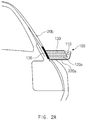
- FIG. 2A illustrates a structure in which an electronic side mirror is attached to a lower-end mounting unit and is disposed outside the vehicle according to various embodiments of the disclosure.
- FIG. 2A illustrates a view of the vehicle 1 viewed from the right rear of the vehicle 1.
- FIG. 2A illustrates the electronic side mirror 130 disposed on the right side of the vehicle 1.
- a similar principle may be applied to the electronic side mirror 130 disposed on the left side of the vehicle 1.
- the side mirror system 100 for a vehicle may include a lower-end mounting unit 220a to support the camera module 110, the moving unit 120, and the electronic side mirror 130 outside the vehicle 1.
- the lower-end mounting unit 220a may be disposed on the right side of the A-pillar 20b.
- the camera module 110 may be mounted on the one side of the lower-end mounting unit 220a so as to obtain an image associated with the right rear of the vehicle 1.
- FIG. 2A illustrates an example in which the camera module 110 is disposed on the rear surface of the lower-end mounting unit 220a.
- the location of the camera module 110 may not be limited to the example illustrated in FIG. 2A .
- the moving unit 120 and the electronic side mirror 130 may be disposed on the top surface of the lower-end mounting unit 220a.
- the moving unit 120 may be disposed at a first location 120a indicating the top surface of the lower-end mounting unit 220a, and the top surface of the moving unit 120 disposed at the first location 120a may be coupled to the bottom surface of the electronic side mirror 130.
- the electronic side mirror 130 coupled to the moving unit 120 may also move to the inside of the vehicle 1.
- the side mirror system 100 for a vehicle may further include a removing unit 136 for removing rainwater or a foreign object from the electronic side mirror 130.
- the removing unit 136 may be located in the middle of the path of the electronic side mirror 130 moving to the inside or the outside of the vehicle 1.
- the removing unit 136 may operate under control of the at least one control circuit 140 or may remove rainwater or a foreign object from the electronic side mirror 130 without a separate control.
- the side mirror system 100 for a vehicle may further include a housing for protecting the electronic side mirror 130.
- the bottom surface of the housing may be coupled to the top surface of the moving unit 120.
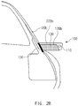
- FIG. 2B illustrates a structure in which an electronic side mirror is attached to an upper-end mounting unit and is disposed outside the vehicle according to various embodiments of the disclosure.
- the side mirror system 100 for a vehicle may include an upper-end mounting unit 220b to support the camera module 110, the moving unit 120, and the electronic side mirror 130 outside the vehicle 1.
- the upper-end mounting unit 220b may be disposed on the right side of the A-pillar 20b.
- the moving unit 120 and the electronic side mirror 130 may be disposed on the bottom surface of the upper-end mounting unit 220b.
- the moving unit 120 may be disposed at a second location 120b indicating the bottom surface of the upper-end mounting unit 220b, and the bottom surface of the moving unit 120 disposed at the second location 120b may be coupled to the top surface of the electronic side mirror 130.
- the side mirror system 100 for a vehicle may further include the removing unit 136 for removing rainwater or a foreign object from the electronic side mirror 130 or a housing for protecting the electronic side mirror 130.
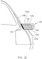
- FIG. 2C illustrates a structure in which an electronic side mirror is attached to a plurality of mounting units and is disposed outside the vehicle according to various embodiments of the disclosure.
- the side mirror system 100 for a vehicle may include the lower-end mounting unit 220a and the upper-end mounting unit 220b.
- the moving unit 120 and the electronic side mirror 130 may be interposed between the bottom surface of the upper-end mounting unit 220b and the top surface of the lower-end mounting unit 220a.
- the moving unit 120 may be at least one.
- the at least one moving unit 120 may be disposed at the first location 120a or the second location 120b.
- FIG. 3 illustrates a side view illustrating a moving unit being coupled to a side surface of an electronic side mirror according to various embodiments of the disclosure.
- FIG. 3 illustrates a view of the vehicle 1 viewed from the right side of the vehicle 1.
- FIG. 3 illustrates an example in which the side mirror system 100 for a vehicle includes the lower-end mounting unit 220a. However, the same principle may be applied to an example including the upper-end mounting unit 220b or a plurality of mounting units.
- the electronic side mirror 130 may be disposed on the top surface of the lower-end mounting unit 220a, and the moving unit 120 may be disposed at a third location 120c indicating the rear surface (a surface on which a screen is not displayed) of the electronic side mirror 130.
- the electronic side mirror 130 may be moved by the moving unit 120 disposed at the third location 120c.
- the location of the moving unit 120 may be at least one of the first location 120a, the second location 120b, and the third location 120c. In embodiments described below, the location of the moving unit 120 or the number of moving units 120 is not limited to the specific location or the specific number.
- FIG. 4A illustrates a structure in which a right electronic side mirror is disposed inside a vehicle according to various embodiments of the disclosure.
- the at least one control circuit 140 may control the moving unit 120 such that the electronic side mirror 130 moves from the outside of the vehicle 1 to the inside of the vehicle 1.
- the electronic side mirror 130 may move from the right side of the A-pillar 20b to the left side of the A-pillar 20b through the moving unit 120.
- the at least one control circuit 140 may control the moving unit 120 such that the electronic side mirror 130 moves to the left.
- the at least one control circuit 140 may fold the moving unit 120 such that the electronic side mirror 130 moves to the inside of the vehicle 1.
- the at least one control circuit 140 may control the moving unit 120 such that the electronic side mirror 130 is disposed at a specified location.
- the specified location may be an area (e.g., the front surface of the air conditioner of a passenger's seat) indicated by a reference numeral 310.
- the specified location may be changed by a user input.
- the at least one control circuit 140 may allow the electronic side mirror 130 to change the tilt of the electronic side mirror 130.
- the tilt of the electronic side mirror 130 may be changed by a user input.
- FIG. 4B illustrates a structure in which a left electronic side mirror is disposed inside a vehicle according to various embodiments of the disclosure.
- the at least one control circuit 140 may control the moving unit 120 such that the electronic side mirror 130 moves from the outside of the vehicle 1 to the inside of the vehicle 1.
- the electronic side mirror 130 may move from the left side of the A-pillar 20a to the right side of the A-pillar 20a through the moving unit 120.
- the at least one control circuit 140 may control the moving unit 120 such that the electronic side mirror 130 is disposed at a specified location.
- the specified location may be an area (e.g., the front surface of the air conditioner of a driver's seat or a space between the A-pillar 20a and a steering wheel 40) indicated by a reference numeral 320.
- the specified location may be changed by a user input.
- the tilt of the electronic side mirror 130 may be changed by the at least one control circuit 140.
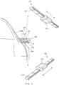
- FIG. 5 illustrates a moving unit including a linear motion (LM) guide structure according to various embodiments of the disclosure.
- FIG. 5 illustrates an example in which the side mirror system 100 for a vehicle includes the lower-end mounting unit 220a and the upper-end mounting unit 220b.
- the same principle may be applied to an example in which the side mirror system 100 for a vehicle includes the lower-end mounting unit 220a or includes the upper-end mounting unit 220b.
- the moving unit 120 may include an LM guide structure.
- the moving unit 120 may include a mounting part 512 and a moving part 514.
- the mounting part 512 may be referred to as a "rail”
- the moving part 514 may be referred to as a "slider”.
- the moving part 514 may straightly move along the mounting part 512.
- the electronic side mirror 130 may move to the outside or the inside of the vehicle 1 while being mounted on the bottom surface of the moving part 514.
- the electronic side mirror 130 may move while being mounted on the top surface of the moving part 514.
- the at least one control circuit 140 may control the moving part 514 to move the moving part 514 along the mounting part 512.
- FIG. 6 illustrates a moving unit including a linear gear structure according to various embodiments of the disclosure.
- FIG. 6 illustrates an example in which the side mirror system 100 for a vehicle includes the lower-end mounting unit 220a and the upper-end mounting unit 220b.
- the same principle may be applied to an example in which the side mirror system 100 for a vehicle includes the lower-end mounting unit 220a or includes the upper-end mounting unit 220b.
- the moving unit 120 may include a linear gear structure.
- the linear gear structure may include a rack and pinion structure.
- the moving unit 120 may include a mounting part 612 and a moving part 614.
- the mounting part 612 may be referred to as a "rack”
- the moving part 614 may be referred to as a "pinion.”
- the moving part 614 may be embedded in the electronic side mirror 130 or may be mounted outside the electronic side mirror 130.
- the moving part 614 may straightly move along the mounting part 612.
- the at least one control circuit 140 may control the moving part 614 such that the moving part 614 moves along the mounting part 612.
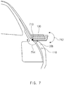
- FIG. 7 illustrates a moving unit including a hinge structure according to various embodiments of the disclosure.
- FIG. 7 illustrates an example in which the side mirror system 100 for a vehicle includes the lower-end mounting unit 220a and the upper-end mounting unit 220b.
- the same principle may be applied to an example in which the side mirror system 100 for a vehicle includes the lower-end mounting unit 220a or includes the upper-end mounting unit 220b.
- the camera module 110 may be mounted in a partial area of the body (e.g., the door 30b) of the vehicle 1.
- the moving unit 120 may include a hinge 710.
- the hinge 710 may be mounted between the lower-end mounting unit 220a and the A-pillar 20b.
- the hinge 710 may be folded in a vertical direction 712 or in a horizontal direction 714.
- the at least one control circuit 140 may fold the hinge 710, and thus may control the electronic side mirror 130 so as to move to the inside of the vehicle 1 together with the lower-end mounting unit 220a.
- FIG. 8 illustrates a structure of an electronic side mirror according to various embodiments of the disclosure.
- the electronic side mirror 130 includes a mirror panel 132 on a front surface and a display panel 134 on a rear surface.
- the mirror panel 132 may include a half mirror, which reflects a part of light and through which the remaining parts of light pass.
- the half mirror may include nickel, aluminum, or titanium on a glass surface, and thus a part of light passes through the half mirror.
- the electronic side mirror 130 When the light incident from the outside is reflected by the mirror panel 132, the electronic side mirror 130 may operate in a mirror mode; when the light irradiated from the display panel 134 passes through the mirror panel 132 and then is output, the electronic side mirror 130 may operate in a display mode.
- the display panel 134 may include an LCD, an organic electro luminescence (OEL), or a PDP.
- the electronic side mirror 130 includes the display panel 134 on a front surface and the mirror panel 132 on a rear surface.
- the display panel 134 may include a transparent display.
- the mirror panel 132 may include a mirror film including a reflective medium.
- the display panel 134 emits light
- the electronic side mirror 130 may operate in the display mode.
- the display panel 134 does not emit light, the light incident from the outside passes through the display panel 134 and then is reflected from the mirror panel 132, and thus the electronic side mirror 130 may operate in the mirror mode.
- the display panel 134 may include an OLED.
- the electronic side mirror 130 may include the display panel 134, and the display panel 134 may include a mirror film 823 performing the function of the mirror panel 132.
- the display panel 134 may be an LCD.
- the display panel 134 may include a back light 850 for supplying light, an upper polarizer 820 and a lower polarizer 840 that reflect or transmit light, which is supplied from the back light, depending on polarization, and an LCD panel 830 that controls the polarization of light.
- the display panel 134 may further include a coating film 810 for protecting the upper polarizer 820.
- the upper polarizer 820 may include a protection layer 821, a polyvinyl alcohol (PVA) film 825 for classifying light, and the mirror film 823 for performing the function of an optical mirror and may include tri-acetyl-cellulose (TAC) films 822, 824, and 826 for protecting the PVA film 825 and the mirror film 823.
- PVA polyvinyl alcohol
- TAC tri-acetyl-cellulose
- the at least one control circuit 140 may control the electronic side mirror 130 to operate in the mirror mode or in the display mode.
- the at least one control circuit 140 may control a light emitting device (e.g., the back light 850) included in the display panel 134 so as not to supply light.
- the light emitting device of the display panel 134 does not supply light, the light incident from the outside is reflected from the mirror panel 134, and thus the electronic side mirror 130 may operate in the mirror mode.
- the electronic side mirror 130 may operate in the display mode.
- FIG. 9 illustrates an operation flowchart of a side mirror system for a vehicle that controls a moving unit such that an electronic side mirror moves to an inside or outside of a vehicle according to various embodiments of the disclosure. Operations illustrated in FIG. 9 may be implemented by the side mirror system 100 for a vehicle or the at least one control circuit 140.
- the at least one control circuit 140 may detect a specified condition.
- the specified condition may include whether a value indicating the outside weather state of the vehicle 1 is not less than a specified critical value.
- the at least one control circuit 140 may determine a value indicating the temperature, humidity, brightness, wind speed, or barometric pressure of the outside of the vehicle 1 through the sensor module 150 and may determine whether the determined value is not less than a specified critical value.
- the at least one control circuit 140 may detect that the outside of the vehicle 1 is in bad visibility (e.g., in the case of rain, fog, night, or the like).
- the specified condition may include whether the display panel 134 operates normally or whether the camera module 110 operates normally.
- the mode of the at least one control circuit 140 may be changed from the display mode to the mirror mode.
- the at least one control circuit 140 may control the moving unit 120 such that the electronic side mirror 130 moves to the outside of the vehicle 1.
- the specified condition may include a user input to move the electronic side mirror 130.
- the at least one control circuit 140 may determine whether the display panel 134 operates normally. When the display panel 134 does not operate normally, the at least one control circuit 140 may control the electronic side mirror 130 so as not to move to the inside of the vehicle 1.
- the at least one control circuit 140 may verify the outside weather state of the vehicle 1. When a value indicating the outside weather state of the vehicle 1 is not less than a critical value, the at least one control circuit 140 may control the electronic side mirror 130 not to move to the outside of the vehicle 1.
- the at least one control circuit 140 may control the moving unit 120 such that the electronic side mirror 130 moves to the outside or the inside of the vehicle 1.
- the at least one control circuit 140 may control the moving unit 120 such that the electronic side mirror 130 moves in a straight direction.
- the at least one control circuit 140 may fold the hinge 710 such that the electronic side mirror 130 moves to the inside of the vehicle 1.
- the at least one control circuit 140 may control the removing unit 136 to operate.
- the at least one control circuit 140 may change the tilt of the electronic side mirror 130.
- FIG. 10 illustrates an operation flowchart of a side mirror system for a vehicle that controls an electronic side mirror based on an outside weather state of a vehicle according to various embodiments of the disclosure.
- the at least one control circuit 140 may specify a value indicating the weather state of the outside of the vehicle 1.
- the at least one control circuit 140 may measure the temperature, humidity, brightness, wind speed, or barometric pressure of the outside of the vehicle 1.
- the at least one control circuit 140 may determine whether the measured value is not less than a specified critical value.
- the specified critical value may be a value stored in the side mirror system 100 for a vehicle or a value specified by a user input.
- the at least one control circuit 140 may periodically implement operation 1005 to operation 1010.
- the at least one control circuit 140 may implement operation 1020.
- the at least one control circuit 140 may control the moving unit 120 such that the electronic side mirror 130 moves from the outside of the vehicle 1 to the inside of the vehicle 1.
- the at least one control circuit 140 may determine whether the display panel 134 operates normally. When the display panel 134 does not operate normally, the at least one control circuit 140 may terminate an algorithm without moving the electronic side mirror 130 to the inside of the vehicle 1.
- the side mirror system 100 for a vehicle may provide an environment in which the electronic side mirror 130 is disposed outside the vehicle 1 and a driver verifies the peripheral area of the vehicle 1 even in bad weather.
- FIG. 11A illustrates a first view of an operation of controlling an electronic side mirror based on an outside weather state of a vehicle according to various embodiments of the disclosure.
- the camera module 110 may obtain an image associated with the peripheral area of the vehicle 1.
- the electronic side mirror 130 may output the image obtained by the camera module 110, through the display panel 134.
- the driver may verify the peripheral area of the vehicle 1 through the electronic side mirror 130 disposed outside the vehicle 1.
- FIG. 11B illustrates a second view of an operation of controlling an electronic side mirror based on an outside weather state of a vehicle according to various embodiments of the disclosure.
- the at least one control circuit 140 may determine that a value indicating the outside weather state is not less than a critical value.
- rainwater or another foreign object
- the front surface of the electronic side mirror 130 It may be inconvenient for a driver to verify the image obtained by the camera module 110.
- FIG. 11C illustrates a third view of an operation of controlling an electronic side mirror based on an outside weather state of a vehicle according to various embodiments of the disclosure.
- the at least one control circuit 140 may control the moving unit 120 such that the electronic side mirror 130 moves to the inside of the vehicle 1.
- a driver may continuously verify the image obtained by the camera module 110.
- FIG. 12 illustrates an operation flowchart of a side mirror system for a vehicle controlling an electronic side mirror based on a user input according to various embodiments of the disclosure.
- An embodiment is exemplified in FIG. 12 as an example to receive a user input to move the electronic side mirror 130 to the inside of the vehicle 1.
- a similar principle may be applied to the example to receive a user input to move the electronic side mirror 130 to the outside of the vehicle 1.
- the at least one control circuit 140 may receive a user input to move the electronic side mirror 130 to the inside of the vehicle 1.
- the at least one control circuit 140 may determine whether the display panel 134 operates normally. For example, due to the damage to the polarizer or the LCD panel included in the display panel 134, the electronic side mirror 130 may fail to display the image obtained by the camera module 110. According to an embodiment of the disclosure, when a signal periodically received from the electronic side mirror 130 is not received within a specified first critical time, the at least one control circuit 140 may determine that the display panel 134 does not operate normally. According to an embodiment of the disclosure, when the at least one control circuit 140 transmits a signal to the electronic side mirror 130 and does not receive a response signal within a specified second critical time, the at least one control circuit 140 may determine that the display panel 134 does not operate normally. According to an embodiment of the disclosure, the electronic side mirror 130 may transmit, to the at least one control circuit 140, a signal indicating that the display panel 134 does not operate normally.
- the at least one control circuit 140 may determine whether the display panel 134 operates normally. When the display panel 134 does not operate normally, the electronic side mirror 130 may not operate in a display mode, and thus the at least one control circuit 140 may implement operation 1220. When the display panel 134 operates normally, the at least one control circuit 140 may implement operation 1225.
- the at least one control circuit 140 may provide a driver with a user interface (UI) indicating that the display panel 134 does not operate normally.
- UI user interface
- the at least one control circuit 140 may provide a notification that the electronic side mirror 130 does not operate in the display mode, through a speaker embedded in the vehicle 1.
- the at least one control circuit 140 may indicate that the electronic side mirror 130 does not operate in the display mode, through another display device (e.g., CID or the display of a navigation device) embedded in the vehicle 1.
- the at least one control circuit 140 may control the moving unit 120 such that the electronic side mirror 130 moves from the outside of the vehicle 1 to the inside of the vehicle 1.
- the side mirror system 100 for a vehicle may notify a user that the electronic side mirror 130 does not operate normally in an environment where the electronic side mirror 130 is capable of being moved depending on a user input.
- FIG. 13 illustrates an operation flowchart of a side mirror system for a vehicle that controls an electronic side mirror based on whether a display panel operates normally according to various embodiments of the disclosure.
- the at least one control circuit 140 may determine whether the display panel 134 operates. For example, the at least one control circuit 140 may receive a signal indicating that the display panel 134 does not operate normally, from the electronic side mirror 130 or may determine whether the signal is received within a specified critical time (e.g., a first critical time or a second critical time), and thus may determine whether the display panel 134 operates normally.
- a specified critical time e.g., a first critical time or a second critical time
- the at least one control circuit 140 may determine whether the display panel 134 operates normally; when the display panel 134 operates normally, the at least one control circuit 140 may repeatedly implement operation 1305 and operation 1310. When the display panel 134 does not operate normally, the at least one control circuit 140 may implement operation 1315.
- the at least one control circuit 140 may change the operating mode of the electronic side mirror 130 from a display mode to a mirror mode.
- the at least one control circuit 140 may allow a light emitting device included in the display panel 134 not to supply light.
- the electronic side mirror 130 may operate in the mirror mode through the mirror panel 132.
- the at least one control circuit 140 may control the moving unit 120 such that the electronic side mirror 130 moves to the outside of the vehicle 1.
- the at least one control circuit 140 may cause the camera module 110 to be turned off for the purpose of reducing the power consumption of the side mirror system 100 for a vehicle.
- FIG. 14A illustrates a first view of an operation of controlling an electronic side mirror based on whether a display panel operates normally according to various embodiments of the disclosure.
- the electronic side mirror 130 is disposed inside the vehicle 1 and operates in a display mode.
- the camera module 110 may obtain an image associated with the peripheral area of the vehicle 1.
- the electronic side mirror 130 may output the image obtained by the camera module 110, through the display panel 134.
- a driver may verify the peripheral area of the vehicle 1 through the electronic side mirror 130 disposed inside the vehicle 1.
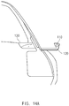
- FIG. 14B illustrates a second view of an operation of controlling an electronic side mirror based on whether a display panel operates normally according to various embodiments of the disclosure.
- the display panel 134 of the electronic side mirror 130 does not operate normally.
- the electronic side mirror 130 may not output the image obtained by the camera module 110, through the display panel 134.
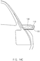
- FIG. 14C illustrates a third view of an operation of controlling an electronic side mirror based on whether a display panel operates normally according to various embodiments of the disclosure.
- the at least one control circuit 140 may change the operating mode of the electronic side mirror 130 to a mirror mode and may control the moving unit 120 such that the electronic side mirror 130 moves to the outside of the vehicle 1.
- a driver may verify the peripheral area of the vehicle 1 through the electronic side mirror 130 operating in the mirror mode.
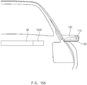
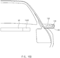
- FIG. 15A illustrates a first view of an operation of controlling a side mirror system for a vehicle including an additional display device according to various embodiments of the disclosure.
- the side mirror system 100 for a vehicle may include an additional display device 1530 inside the vehicle 1.
- the display device 1530 may be disposed in a dashboard 50 (or a part of a trim).
- the display device 1530 may include a display panel (e.g., the display panel 134).
- the display panel may include one of an LCD, a TFT LCD, an OLED, or a PDP.
- the display device 1530 may output an image indicating a color of the dashboard 50.
- the color of the dashboard 50 may include a wood grain or a metal grain.
- the tilt of the display device 1530 may be changed.
- the at least one control circuit 140 may change the tilt of the display device 1530 based on the specified value or may change the tilt of the display device 1530 in response to a user input.
- FIG. 15B illustrates a second view of an operation of controlling a side mirror system for a vehicle including an additional display device according to various embodiments of the disclosure.
- the at least one control circuit 140 may determine that a value indicating the outside weather state is not less than a critical value.
- rainwater or another foreign object
- the front surface of the electronic side mirror 130 It may be inconvenient for a driver to verify the image obtained by the camera module 110.
- FIG. 15B An embodiment is exemplified in FIG. 15B as the outside weather state of the vehicle 1 is bad weather.
- the same principle may be applied to an example in which the electronic side mirror 130 is disposed outside the vehicle 1 and the display panel 134 does not operate normally.
- FIG. 15C illustrates a third view of an operation of controlling a side mirror system for a vehicle including an additional display device according to various embodiments of the disclosure.
- the at least one control circuit 140 may control the display device 1530 so as to output the image obtained by the camera module 110, in response to the fact that the value indicating the weather state of the outside of the vehicle 1 is not less than a critical value or in response to detecting that the display panel 134 does not operate normally.
- the side mirror system 100 for a vehicle may output the image obtained by the camera module 110, through the additional display device 1530, and thus may provide a backup environment when the electronic side mirror 130 does not operate normally.
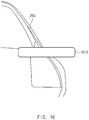
- FIG. 16 illustrates a side mirror system for a vehicle in which a plurality of electronic side mirrors are integrally formed according to various embodiments of the disclosure.
- the side mirror system 100 for a vehicle may include an integrated electronic side mirror 1616 in which a plurality of electronic side mirrors are integrally formed.
- the integrated electronic side mirror 1616 may include the electronic side mirror 130 and the display device 1530.
- a part of the integrated electronic side mirror 1616 may be disposed outside the vehicle 1 (e.g., the right side of the A-pillar 20b), and the remaining parts of the integrated electronic side mirror 1616 may be disposed inside the vehicle 1 (e.g., the front surface of the air conditioner of a passenger's seat).
- the integrated electronic side mirror 1616 may output the image obtained by the camera module 110. According to an embodiment of the disclosure, a part of the integrated electronic side mirror 1616 may output the image obtained by the camera module 110, and the remaining part may fail to output the image. According to an embodiment of the disclosure, a part of the integrated electronic side mirror 1616 may output the image obtained by the camera module 110, and the remaining part may output an image associated with the front blind spot generated by the A-pillar 20b.
- a side mirror system for a vehicle may include a camera module (e.g., the camera module 110 of FIG. 1 ) disposed outside the vehicle (e.g., the vehicle 1 of FIG. 1 ) and capturing a peripheral area of the vehicle, an electronic side mirror (e.g., the electronic side mirror 130 of FIG. 1 ) including a mirror panel (e.g., the mirror panel 132 of FIG. 8 ) and a display panel (e.g., the display panel 134 of FIG. 8 ), a moving unit (e.g., the moving unit 120 of FIG.
- a camera module e.g., the camera module 110 of FIG. 1
- an electronic side mirror e.g., the electronic side mirror 130 of FIG. 1
- a mirror panel e.g., the mirror panel 132 of FIG. 8
- a display panel e.g., the display panel 134 of FIG. 8
- a moving unit e.g., the moving unit 120 of FIG.
- the at least one control circuit may be configured to control the electronic side mirror such that the electronic side mirror outputs an image obtained by the camera module through the display panel or the peripheral area of the vehicle is reflected by the mirror panel and to control the moving unit such that the electronic side mirror moves from the outside of the vehicle to the inside of the vehicle, when a specified condition is satisfied.
- the side mirror system for the vehicle may further include a removing unit (e.g., the removing unit 136 of FIG. 2A ).
- the at least one control circuit may be configured to control the removing unit to remove rainwater or a foreign object from the electronic side mirror, while the electronic side mirror moves from the outside of the vehicle to the inside of the vehicle.
- the moving unit may include one of a LM guide structure or a linear gear structure, and the at least one control circuit may be configured to control the moving unit such that the electronic side mirror moves left or right.
- the moving unit may include a hinge. The at least one control circuit may be configured to control the moving unit such that the hinge is folded.
- the side mirror system for the vehicle may further include a sensor module (e.g., the sensor module 150 of FIG. 1 ) measuring an outside weather state of the vehicle.
- the at least one control circuit may be configured to determine a value indicating the outside weather state of the vehicle through the sensor module and to control the moving unit such that the electronic side mirror moves from the outside of the vehicle to the inside of the vehicle, when the determined value is not less than a specified critical value.
- the at least one control circuit may be configured to detect whether the display panel operates normally and to control the electronic side mirror such that the peripheral area of the vehicle is reflected by the mirror panel, when the display panel does not operate normally.
- the at least one control circuit may be configured to receive a user input to move the electronic side mirror from the outside of the vehicle to the inside of the vehicle, to detect whether the display panel operates normally, and to control the moving unit such that the electronic side mirror moves from the outside of the vehicle to the inside of the vehicle, when the display panel operates normally.
- the side mirror system for the vehicle may further include a display device (e.g., the display device 1530 of FIG. 15A ) inside the vehicle.
- the at least one control circuit may be configured to control the display device so as to output the image obtained by the camera module regardless of the specified condition.
- a side mirror system for a vehicle may include a sensor module (e.g., the sensor module 150 of FIG. 1 ), a camera module (e.g., the camera module 110 of FIG. 1 ) disposed outside the vehicle (e.g., the vehicle 1 of FIG. 1 ) and capturing a peripheral area of the vehicle, an electronic side mirror (e.g., the electronic side mirror 130 of FIG. 1 ) including a mirror panel (e.g., the mirror panel 132 of FIG. 8 ) and a display panel, a moving unit (e.g., the moving unit 120 of FIG.
- a sensor module e.g., the sensor module 150 of FIG. 1
- a camera module e.g., the camera module 110 of FIG. 1
- an electronic side mirror e.g., the electronic side mirror 130 of FIG. 1
- a mirror panel e.g., the mirror panel 132 of FIG. 8
- a moving unit e.g., the moving unit 120 of FIG.
- the at least one control circuit may be configured to control the electronic side mirror such that the electronic side mirror outputs an image obtained by the camera module through the display panel or the peripheral area of the vehicle is reflected by the mirror panel, to detect an outside weather state of the vehicle through the sensor module, and to control the moving unit such that the electronic side mirror moves from the outside of the vehicle to the inside of the vehicle.
- the side mirror system for the vehicle may further include a removing unit (e.g., the removing unit 136 of FIG. 2A ).
- the at least one control circuit may be configured to control the removing unit to remove rainwater or a foreign object from the electronic side mirror, while the electronic side mirror moves from the outside of the vehicle to the inside of the vehicle.
- the moving unit may include one of a LM guide structure or a linear gear structure, and the at least one control circuit may be configured to control the moving unit such that the electronic side mirror moves left or right.
- the moving unit may include a hinge. The at least one control circuit may be configured to control the moving unit such that the hinge is folded.
- the at least one control circuit may be configured to detect whether the display panel operates normally and to control the electronic side mirror such that the peripheral area of the vehicle is reflected by the mirror panel, when the display panel does not operate normally.
- the at least one control circuit may be configured to control the electronic side mirror such that a tilt of the electronic side mirror is changed, when the electronic side mirror moves to the inside of the vehicle.
- the side mirror system for the vehicle may further include a display device (e.g., the display device 1530 of FIG. 15A ) inside the vehicle.
- the at least one control circuit may be configured to control the display device so as to output the image obtained by the camera module regardless of the specified condition.
- a method of a side mirror system for a vehicle may include detecting a specified condition and controlling a moving unit such that an electronic side mirror including a mirror panel and a display panel moves from an outside of the vehicle to an inside of the vehicle.
- the electronic side mirror may be configured to output an image obtained by a camera module through the display panel or is configured such that a peripheral area of the vehicle is reflected by the mirror panel.
- the detecting of the specified condition may include detecting an outside weather state of the vehicle and determining whether a value indicating the outside weather state of the vehicle is not less than a specified critical value.
- the method may further include detecting whether the display panel operates normally, when the value indicating the outside weather state of the vehicle is not less than the specified critical value and controlling the moving unit such that the electronic side mirror moves from the outside of the vehicle to the inside of the vehicle, when the display panel operates normally.
- the method may further include controlling the electronic side mirror such that the peripheral area of the vehicle is reflected by the mirror panel, when the display panel does not operate normally.
- the method may further include controlling the camera module so as to be turned off.
- a first”, “a second”, “the first”, or “the second”, used in herein may refer to various components regardless of the order and/or the importance, but do not limit the corresponding components.
- the above expressions are used merely for the purpose of distinguishing a component from the other components. It should be understood that when a component (e.g., a first component) is referred to as being (operatively or communicatively) "connected,” or “coupled,” to another component (e.g., a second component), it may be directly connected or coupled directly to the other component or any other component (e.g., a third component) may be interposed between them.
- module used herein may represent, for example, a unit including one or more combinations of hardware, software and firmware.
- module may be interchangeably used with the terms “logic”, “logical block”, “part” and “circuit”.
- the “module” may be a minimum unit of an integrated part or may be a part thereof.
- the “module” may be a minimum unit for performing one or more functions or a part thereof.
- the “module” may include an ASIC.
- Various embodiments of the disclosure may be implemented by software including an instruction stored in a machine-readable storage media readable by a machine (e.g., a computer).
- the machine may be a device that calls the instruction from the machine-readable storage media and operates depending on the called instruction and may include the electronic device.
- the processor e.g., the control circuit 140
- the processor may perform a function corresponding to the instruction directly or using other components under the control of the processor.
- the instruction may include a code generated or executed by a compiler or an interpreter.
- the machine-readable storage media may be provided in the form of non-transitory storage media.
- non-transitory is a limitation of the medium itself (i.e., tangible, not a signal) as opposed to a limitation on data storage persistency.
- the method according to various embodiments disclosed in the disclosure may be provided as a part of a computer program product.
- the computer program product may be traded between a seller and a buyer as a product.
- the computer program product may be distributed in the form of machine-readable storage medium (e.g., a compact disc-read only memory (CD-ROM)) or may be distributed only through an application store (e.g., a Play StoreTM).
- an application store e.g., a Play StoreTM
- at least a portion of the computer program product may be temporarily stored or generated in a storage medium, such as a memory of a manufacturer's server, an application store's server, or a relay server.
- Each component may include at least one of the above components, and a portion of the above sub-components may be omitted, or additional other sub-components may be further included.
- some components e.g., the module or the program
- Operations performed by a module, a programming, or other components according to various embodiments of the disclosure may be executed sequentially, in parallel, repeatedly, or in a heuristic method.
- at least some operations may be executed in different sequences, omitted, or other operations may be added.
Landscapes
- Engineering & Computer Science (AREA)
- Multimedia (AREA)
- Mechanical Engineering (AREA)
- Physics & Mathematics (AREA)
- General Physics & Mathematics (AREA)
- Optics & Photonics (AREA)
- Rear-View Mirror Devices That Are Mounted On The Exterior Of The Vehicle (AREA)
Description
- The disclosure relates to an apparatus and a method for controlling a side mirror system for a vehicle. More particularly, the disclosure relates to a method of moving an electronic side mirror to the inside of the vehicle under a specified condition, while an electronic side mirror is disposed outside a vehicle.
- For the purpose of verifying the peripheral area of a vehicle, the vehicle may include side mirrors in the right side and the left side of the vehicle. A driver may verify the peripheral area of the vehicle by using light reflected from optical mirrors of the side mirrors. For the purpose of addressing the inconvenience that the driver can not verify blind spots of the side mirrors, the vehicle may include an electronic side mirror (E side mirror) instead of a side mirror including an optical mirror. The electronic side mirror may include a display. The display may output an image, which is obtained by a camera module mounted in the vehicle and which is associated with the peripheral area of the vehicle. The camera module may obtain the image of a range wider than the optical mirror.
- The above information is presented as background information only to assist with an understanding of the disclosure. No determination has been made, and no assertion is made, as to whether any of the above might be applicable as prior art with regard to the disclosure.
-
JP2010116125 - With the development of an electronic side mirror, a location where an electronic side mirror is disposed may be discussed. When the electronic side mirror is interposed between a driver's seat and a passenger's seat as a center information display (CID) or is disposed on a dashboard or in a rear-view mirror, the electronic side mirror may violate regulations of European Union (EU) and the driver of the vehicle may feel inconvenience because the driver needs to verify a peripheral area of the vehicle in a direction different from the existing direction. When the electronic side mirror is disposed inside an A-pillar, the driver's view may not be secured. When the electronic side mirror is disposed on a cluster, the driver's eyes may be fatigued due to an image always output by a display. When the electronic side mirror is disposed at a location the same as the side mirror of the related art, the driver may feel inconvenience to verify the peripheral area of the vehicle in a weather state of poor visibility.
- Furthermore, in the case where the display of the electronic side mirror does not operate normally, the vehicle may not output the image obtained through a camera module, to the driver of the vehicle.
- Aspects of the disclosure are to address at least the above-mentioned problems and/or disadvantages and to provide at least the advantages described below. Accordingly, an aspect of the disclosure is to provide a method of moving an electronic side mirror to the inside of the vehicle under a specified condition, while an electronic side mirror is disposed outside a vehicle.
- Another aspect of the disclosure is to provide a method in which an electronic side mirror operates in a mirror mode when a display of the electronic side mirror does not operate normally.
- Additional aspects will be set forth in part in the description which follows and, in part, will be apparent from the description, or may be learned by practice of the presented embodiments.
- According to the invention a side mirror system for a vehicle according to claim 1 and a method of operating a side mirror system for a vehicle according to claim 11 is provided.
- According to various embodiments of the disclosure, a side mirror system for a vehicle may include an electronic side mirror disposed outside the vehicle, thereby preventing a driver from feeling inconvenience or fatigue without violating regulations of EU.
- According to various embodiments of the disclosure, a side mirror system for a vehicle may control a moving device such that an electronic side mirror moves to the inside or the outside of the vehicle, and thus may provide an environment in which a driver is capable of verifying the peripheral area of the vehicle even in bad weather.
- According to various embodiments of the disclosure, a side mirror system for a vehicle may control an electronic side mirror so as to perform the function of an optical mirror, and thus may provide a driver with a backup environment when a display does not operate normally.
- Besides, a variety of effects directly or indirectly understood through this disclosure may be provided.
- Other aspects, advantages, and salient features of the disclosure will become apparent to those skilled in the art from the following detailed description, which, taken in conjunction with the annexed drawings, discloses various embodiments of the disclosure.
- The above and other aspects, features, and advantages of certain embodiments of the disclosure will be more apparent from the following description taken in conjunction with the accompanying drawings, in which:
-
FIG. 1 illustrates a vehicle including a side mirror system for a vehicle according to various embodiments of the disclosure; -
FIG. 2A illustrates a structure in which an electronic side mirror is attached to a lower-end mounting unit and is disposed outside the vehicle according to various embodiments of the disclosure; -
FIG. 2B illustrates a structure in which an electronic side mirror is attached to an upper-end mounting unit and is disposed outside the vehicle according to various embodiments of the disclosure; -
FIG. 2C illustrates a structure in which an electronic side mirror is attached to a plurality of mounting units and is disposed outside the vehicle according to various embodiments of the disclosure; -
FIG. 3 illustrates a side view illustrating a moving unit being coupled to a side surface of an electronic side mirror according to various embodiments of the disclosure; -
FIG. 4A illustrates a structure in which a right electronic side mirror is disposed inside a vehicle according to various embodiments of the disclosure; -
FIG. 4B illustrates a structure in which a left electronic side mirror is disposed inside a vehicle according to various embodiments of the disclosure; -
FIG. 5 illustrates a moving unit including a linear motion (LM) guide structure according to various embodiments of the disclosure; -
FIG. 6 illustrates a moving unit including a linear gear structure according to various embodiments of the disclosure; -
FIG. 7 illustrates a moving unit including a hinge structure according to various embodiments of the disclosure; -
FIG. 8 illustrates a structure of an electronic side mirror according to various embodiments of the disclosure; -
FIG. 9 illustrates an operation flowchart of a side mirror system for a vehicle that controls a moving unit such that an electronic side mirror moves to an inside or outside of a vehicle according to various embodiments of the disclosure; -
FIG. 10 illustrates an operation flowchart of a side mirror system for a vehicle that controls an electronic side mirror based on an outside weather state of a vehicle according to various embodiments of the disclosure; -
FIG. 11A illustrates a first view of an operation of controlling an electronic side mirror based on an outside weather state of a vehicle according to various embodiments of the disclosure; -
FIG. 11B illustrates a second view of an operation of controlling an electronic side mirror based on an outside weather state of a vehicle according to various embodiments of the disclosure; -
FIG. 11C illustrates a third view of an operation of controlling an electronic side mirror based on an outside weather state of a vehicle according to various embodiments of the disclosure; -
FIG. 12 illustrates an operation flowchart of a side mirror system for a vehicle controlling an electronic side mirror based on a user input according to various embodiments of the disclosure; -
FIG. 13 illustrates an operation flowchart of a side mirror system for a vehicle that controls an electronic side mirror based on whether a display panel operates normally according to various embodiments of the disclosure; -
FIG. 14A illustrates a first view of an operation of controlling an electronic side mirror based on whether a display panel operates normally according to various embodiments of the disclosure; -
FIG. 14B illustrates a second view of an operation of controlling an electronic side mirror based on whether a display panel operates normally according to various embodiments of the disclosure; -
FIG. 14C illustrates a third view of an operation of controlling an electronic side mirror based on whether a display panel operates normally according to various embodiments of the disclosure; -
FIG. 15A illustrates a first view of an operation of controlling a side mirror system for a vehicle including an additional display device according to various embodiments of the disclosure; -
FIG. 15B illustrates a second view of an operation of controlling a side mirror system for a vehicle including an additional display device according to various embodiments of the disclosure; -
FIG. 15C illustrates a third view of an operation of controlling a side mirror system for a vehicle including an additional display device according to various embodiments of the disclosure; and -
FIG. 16 illustrates a side mirror system for a vehicle in which a plurality of electronic side mirrors are integrally formed according to various embodiments of the disclosure. - Throughout the drawings, like reference numerals will be understood to refer to like parts, components, and structures.
- The following description with reference to the accompanying drawings is provided to assist in a comprehensive understanding of various embodiments of the disclosure as defined by the claims and their equivalents. It includes various specific details to assist in that understanding but these are to be regarded as merely exemplary. Accordingly, those of ordinary skill in the art will recognize that various changes and modifications, of the various embodiments described herein can be made without departing from the scope and spirit of the disclosure. In addition, descriptions of well-known functions and constructions may be omitted for clarity and conciseness.
- The terms and words used in the following description and claims are not limited to the bibliographical meanings, but, are merely used by the inventor to enable a clear and consistent understanding of the disclosure. Accordingly, it should be apparent to those skilled in the art that the following description of various embodiments of the disclosure is provided for illustration purpose only and not for the purpose of limiting the disclosure as defined by the appended claims and their equivalents.
- It is to be understood that the singular forms "a," "an," and "the" include plural referents unless the context clearly dictates otherwise. Thus, for example, reference to "a component surface" includes reference to one or more of such surfaces.
- By the term "substantially" it is meant that the recited characteristic, parameter, or value need not be achieved exactly, but that deviations or variations, including for example, tolerances, measurement error, measurement accuracy limitations and other factors known to those of skill in the art, may occur in amounts that do not preclude the effect the characteristic was intended to provide.
-
FIG. 1 illustrates a vehicle including a side mirror system for a vehicle according to various embodiments of the disclosure. - Referring to
FIG. 1 , a vehicle 1 may include aside mirror system 100 for a vehicle used to verify the peripheral area of the vehicle 1. Theside mirror system 100 for a vehicle may include a camera module 110 (or, a camera 110), a movingunit 120, anelectronic side mirror 130, at least onecontrol circuit 140, and asensor module 150. According to an embodiment of the disclosure, the vehicle 1 may not include a part of components illustrated inFIG. 1 or may further include a new component. For example, the vehicle 1 may not include thesensor module 150 and may include an input device that receives a user input. For another example, the vehicle 1 may further include a removing unit that removes rainwater or a foreign object from the front surface of theelectronic side mirror 130. - According to an embodiment of the disclosure, the
camera module 110 may obtain an image associated with the peripheral area of the vehicle 1. Thecamera module 110 may be disposed outside the vehicle 1. For example, the left camera module may be disposed on the left side of an A-pillar 20a, and the right camera module may be disposed on the right side of an A-pillar 20b. For another example, each of the left camera module and the right camera module may be disposed in the body (e.g.,doors - According to an embodiment of the disclosure, the
camera module 110 may include at least one lens assembly capable of collecting light emitted from a subject, a flash capable of emitting a light source used to strengthen light emitted from the subject, an image sensor capable of converting light transmitted from the subject through the lens assembly into an electrical signal, an image stabilizer capable of at least partly compensating (e.g., adjust read-out timing) for negative effects (e.g., image blurring) caused by the movement of thecamera module 110 or the vehicle 1, a memory capable of temporarily storing at least part of the image obtained through the image sensor, or an image signal processor capable of performing processing (e.g., noise reduction, resolution adjustment, brightness adjustment, blurring, sharpening, or softening) on an image obtained through the image sensor or an image stored in the memory. According to an embodiment of the disclosure, the image signal processor may not be included in thecamera module 110, and may be included in the at least onecontrol circuit 140. - According to an embodiment of the disclosure, the
electronic side mirror 130 may be used such that the driver of the vehicle 1 verifies the peripheral area of the vehicle 1. Theelectronic side mirror 130 may be disposed outside the vehicle 1. According to the invention, theelectronic side mirror 130 is moved from the outside of the vehicle 1 to the inside of the vehicle 1 by the movingunit 120, or vice versa. - According to an embodiment of the disclosure, the
electronic side mirror 130 may include a display panel that outputs an image obtained from thecamera module 110. For example, the display panel may include at least one of a liquid crystal display (LCD), a thin film transistor-liquid crystal display (TFT LCD), an organic light-emitting diode (OLED), and a plasma display panel (PDP). - According to an embodiment of the disclosure, the
electronic side mirror 130 may include a mirror panel to perform the function of an optical mirror that reflects the peripheral area of the vehicle through the reflection of light. For example, the mirror panel may include a mirror film that reflects all of the light or may include a half mirror film, which reflects a part of light and through which the remaining parts of light pass. Theelectronic side mirror 130 may perform the function of an optical mirror through a mirror panel or may perform the function of an electronic display through a display panel. In the disclosure, a state where theelectronic side mirror 130 performs the function of the optical mirror may be referred to as a "mirror mode"; a state where theelectronic side mirror 130 performs the function of the electronic display may be referred to as a "display mode". An example in which theelectronic side mirror 130 operates in the mirror mode or the display mode will be described with reference toFIG. 9 . - According to an embodiment of the disclosure, the moving
unit 120 may move theelectronic side mirror 130 to the outside or the inside of the vehicle 1. According to an embodiment of the disclosure, the movingunit 120 may be disposed over the inside and the outside of the vehicle 1 through a hole disposed on the side surface (e.g., the A-pillar 20a or 20b) of the vehicle 1. According to an embodiment of the disclosure, the movingunit 120 may include a rail, linear gear, or hinge structure to move theelectronic side mirror 130. - According to an embodiment of the disclosure, the at least one
control circuit 140 may include a software or hardware module. For example, the at least onecontrol circuit 140 may include at least one of application specific integrated circuits (ASICs), digital signal processors (DSPs), digital signal processing devices (DSPDs), programmable logic devices (PLDs), field programmable gate arrays (FPGAs), processors, controllers, micro-controllers, and microprocessors. According to an embodiment of the disclosure, the at least onecontrol circuit 140 may be referred to as an "electronic control unit (ECU)". - According to an embodiment of the disclosure, the at least one
control circuit 140 may be electrically connected to thecamera module 110, the movingunit 120, and theelectronic side mirror 130. For example, the at least onecontrol circuit 140 may communicate with other components through a controller area network (CAN) communication protocol of the vehicle 1. - According to an embodiment of the disclosure, the at least one
control circuit 140 may perform the overall function of theside mirror system 100 for a vehicle. For example, the at least onecontrol circuit 140 may process the image obtained by thecamera module 110 and may output the processed image through theelectronic side mirror 130. For another example, the at least onecontrol circuit 140 may control the movingunit 120 such that theelectronic side mirror 130 moves to the inside or outside of the vehicle 1 based on a specified condition. For example, the specified condition may include a user input, an outside weather condition of the vehicle 1 detected by thesensor module 150, whether thecamera module 110 fails, or whether a display panel included in theelectronic side mirror 130 fails. - According to an embodiment of the disclosure, the
sensor module 150 may detect the outside weather condition of the vehicle 1 by measuring the temperature, humidity, brightness, wind speed, or barometric pressure of the outside of the vehicle 1. There are one ormore sensor modules 150. Thesensor module 150 may transmit information about the outside weather condition to the at least onecontrol circuit 140. -
FIG. 2A illustrates a structure in which an electronic side mirror is attached to a lower-end mounting unit and is disposed outside the vehicle according to various embodiments of the disclosure.FIG. 2A illustrates a view of the vehicle 1 viewed from the right rear of the vehicle 1.FIG. 2A illustrates theelectronic side mirror 130 disposed on the right side of the vehicle 1. However, a similar principle may be applied to theelectronic side mirror 130 disposed on the left side of the vehicle 1. - Referring to
FIG. 2A , theside mirror system 100 for a vehicle may include a lower-end mounting unit 220a to support thecamera module 110, the movingunit 120, and theelectronic side mirror 130 outside the vehicle 1. According to an embodiment of the disclosure, the lower-end mounting unit 220a may be disposed on the right side of the A-pillar 20b. - According to an embodiment of the disclosure, the
camera module 110 may be mounted on the one side of the lower-end mounting unit 220a so as to obtain an image associated with the right rear of the vehicle 1.FIG. 2A illustrates an example in which thecamera module 110 is disposed on the rear surface of the lower-end mounting unit 220a. However, the location of thecamera module 110 may not be limited to the example illustrated inFIG. 2A . - According to an embodiment of the disclosure, the moving
unit 120 and theelectronic side mirror 130 may be disposed on the top surface of the lower-end mounting unit 220a. For example, the movingunit 120 may be disposed at afirst location 120a indicating the top surface of the lower-end mounting unit 220a, and the top surface of the movingunit 120 disposed at thefirst location 120a may be coupled to the bottom surface of theelectronic side mirror 130. When the movingunit 120 moves to the inside of the vehicle 1 under control of the at least onecontrol circuit 140, theelectronic side mirror 130 coupled to the movingunit 120 may also move to the inside of the vehicle 1. - According to an embodiment of the disclosure, the
side mirror system 100 for a vehicle may further include a removingunit 136 for removing rainwater or a foreign object from theelectronic side mirror 130. According to an embodiment of the disclosure, the removingunit 136 may be located in the middle of the path of theelectronic side mirror 130 moving to the inside or the outside of the vehicle 1. The removingunit 136 may operate under control of the at least onecontrol circuit 140 or may remove rainwater or a foreign object from theelectronic side mirror 130 without a separate control. - According to an embodiment of the disclosure, the
side mirror system 100 for a vehicle may further include a housing for protecting theelectronic side mirror 130. In the case where theside mirror system 100 for a vehicle further includes the housing, the bottom surface of the housing may be coupled to the top surface of the movingunit 120. -
FIG. 2B illustrates a structure in which an electronic side mirror is attached to an upper-end mounting unit and is disposed outside the vehicle according to various embodiments of the disclosure. - Referring to
FIG. 2B , theside mirror system 100 for a vehicle may include an upper-end mounting unit 220b to support thecamera module 110, the movingunit 120, and theelectronic side mirror 130 outside the vehicle 1. According to an embodiment of the disclosure, the upper-end mounting unit 220b may be disposed on the right side of the A-pillar 20b. - According to an embodiment of the disclosure, the moving
unit 120 and theelectronic side mirror 130 may be disposed on the bottom surface of the upper-end mounting unit 220b. For example, the movingunit 120 may be disposed at asecond location 120b indicating the bottom surface of the upper-end mounting unit 220b, and the bottom surface of the movingunit 120 disposed at thesecond location 120b may be coupled to the top surface of theelectronic side mirror 130. - According to an embodiment of the disclosure, the
side mirror system 100 for a vehicle may further include the removingunit 136 for removing rainwater or a foreign object from theelectronic side mirror 130 or a housing for protecting theelectronic side mirror 130. -
FIG. 2C illustrates a structure in which an electronic side mirror is attached to a plurality of mounting units and is disposed outside the vehicle according to various embodiments of the disclosure. - Referring to
FIG. 2C , theside mirror system 100 for a vehicle may include the lower-end mounting unit 220a and the upper-end mounting unit 220b. The movingunit 120 and theelectronic side mirror 130 may be interposed between the bottom surface of the upper-end mounting unit 220b and the top surface of the lower-end mounting unit 220a. According to an embodiment of the disclosure, the movingunit 120 may be at least one. The at least one movingunit 120 may be disposed at thefirst location 120a or thesecond location 120b. -
FIG. 3 illustrates a side view illustrating a moving unit being coupled to a side surface of an electronic side mirror according to various embodiments of the disclosure.FIG. 3 illustrates a view of the vehicle 1 viewed from the right side of the vehicle 1.FIG. 3 illustrates an example in which theside mirror system 100 for a vehicle includes the lower-end mounting unit 220a. However, the same principle may be applied to an example including the upper-end mounting unit 220b or a plurality of mounting units. - Referring to
FIG. 3 , theelectronic side mirror 130 may be disposed on the top surface of the lower-end mounting unit 220a, and the movingunit 120 may be disposed at athird location 120c indicating the rear surface (a surface on which a screen is not displayed) of theelectronic side mirror 130. Theelectronic side mirror 130 may be moved by the movingunit 120 disposed at thethird location 120c. - According to an embodiment of the disclosure, the location of the moving
unit 120 may be at least one of thefirst location 120a, thesecond location 120b, and thethird location 120c. In embodiments described below, the location of the movingunit 120 or the number of movingunits 120 is not limited to the specific location or the specific number. -
FIG. 4A illustrates a structure in which a right electronic side mirror is disposed inside a vehicle according to various embodiments of the disclosure. - Referring to
FIG. 4A , when a specified condition is satisfied, the at least onecontrol circuit 140 may control the movingunit 120 such that theelectronic side mirror 130 moves from the outside of the vehicle 1 to the inside of the vehicle 1. In other words, theelectronic side mirror 130 may move from the right side of the A-pillar 20b to the left side of the A-pillar 20b through the movingunit 120. For example, when the movingunit 120 includes a rail structure or a linear gear structure, the at least onecontrol circuit 140 may control the movingunit 120 such that theelectronic side mirror 130 moves to the left. For another example, when the movingunit 120 includes a hinge structure, the at least onecontrol circuit 140 may fold the movingunit 120 such that theelectronic side mirror 130 moves to the inside of the vehicle 1. - According to an embodiment of the disclosure, the at least one
control circuit 140 may control the movingunit 120 such that theelectronic side mirror 130 is disposed at a specified location. For example, the specified location may be an area (e.g., the front surface of the air conditioner of a passenger's seat) indicated by areference numeral 310. According to an embodiment of the disclosure, the specified location may be changed by a user input. - According to an embodiment of the disclosure, while the
electronic side mirror 130 moves to the inside of the vehicle 1, or after theelectronic side mirror 130 moves to the inside of the vehicle 1, the at least onecontrol circuit 140 may allow theelectronic side mirror 130 to change the tilt of theelectronic side mirror 130. According to an embodiment of the disclosure, the tilt of theelectronic side mirror 130 may be changed by a user input. -
FIG. 4B illustrates a structure in which a left electronic side mirror is disposed inside a vehicle according to various embodiments of the disclosure. - Referring to
FIG. 4B , the at least onecontrol circuit 140 may control the movingunit 120 such that theelectronic side mirror 130 moves from the outside of the vehicle 1 to the inside of the vehicle 1. In other words, theelectronic side mirror 130 may move from the left side of the A-pillar 20a to the right side of the A-pillar 20a through the movingunit 120. According to an embodiment of the disclosure, the at least onecontrol circuit 140 may control the movingunit 120 such that theelectronic side mirror 130 is disposed at a specified location. For example, the specified location may be an area (e.g., the front surface of the air conditioner of a driver's seat or a space between the A-pillar 20a and a steering wheel 40) indicated by areference numeral 320. According to an embodiment of the disclosure, the specified location may be changed by a user input. According to an embodiment of the disclosure, while theelectronic side mirror 130 moves to the inside of the vehicle 1 or after theelectronic side mirror 130 moves to the inside of the vehicle 1, the tilt of theelectronic side mirror 130 may be changed by the at least onecontrol circuit 140. -
FIG. 5 illustrates a moving unit including a linear motion (LM) guide structure according to various embodiments of the disclosure.FIG. 5 illustrates an example in which theside mirror system 100 for a vehicle includes the lower-end mounting unit 220a and the upper-end mounting unit 220b. However, the same principle may be applied to an example in which theside mirror system 100 for a vehicle includes the lower-end mounting unit 220a or includes the upper-end mounting unit 220b. - Referring to
FIG. 5 , the movingunit 120 may include an LM guide structure. The movingunit 120 may include a mountingpart 512 and a movingpart 514. According to an embodiment of the disclosure, the mountingpart 512 may be referred to as a "rail", and the movingpart 514 may be referred to as a "slider". The movingpart 514 may straightly move along the mountingpart 512. As illustrated in areference numeral 510, when the movingunit 120 is positioned at thesecond location 120b, theelectronic side mirror 130 may move to the outside or the inside of the vehicle 1 while being mounted on the bottom surface of the movingpart 514. As illustrated in areference numeral 520, when the movingunit 120 is positioned at thefirst location 120a, theelectronic side mirror 130 may move while being mounted on the top surface of the movingpart 514. According to an embodiment of the disclosure, when a specified condition is satisfied, the at least onecontrol circuit 140 may control the movingpart 514 to move the movingpart 514 along the mountingpart 512. -
FIG. 6 illustrates a moving unit including a linear gear structure according to various embodiments of the disclosure.FIG. 6 illustrates an example in which theside mirror system 100 for a vehicle includes the lower-end mounting unit 220a and the upper-end mounting unit 220b. However, the same principle may be applied to an example in which theside mirror system 100 for a vehicle includes the lower-end mounting unit 220a or includes the upper-end mounting unit 220b. - Referring to
FIG. 6 , the movingunit 120 may include a linear gear structure. For example, the linear gear structure may include a rack and pinion structure. The movingunit 120 may include a mountingpart 612 and a movingpart 614. According to an embodiment of the disclosure, the mountingpart 612 may be referred to as a "rack," and the movingpart 614 may be referred to as a "pinion." According to an embodiment of the disclosure, the movingpart 614 may be embedded in theelectronic side mirror 130 or may be mounted outside theelectronic side mirror 130. The movingpart 614 may straightly move along the mountingpart 612. According to an embodiment of the disclosure, when a specified condition is satisfied, the at least onecontrol circuit 140 may control the movingpart 614 such that the movingpart 614 moves along the mountingpart 612. -
FIG. 7 illustrates a moving unit including a hinge structure according to various embodiments of the disclosure.FIG. 7 illustrates an example in which theside mirror system 100 for a vehicle includes the lower-end mounting unit 220a and the upper-end mounting unit 220b. However, the same principle may be applied to an example in which theside mirror system 100 for a vehicle includes the lower-end mounting unit 220a or includes the upper-end mounting unit 220b. - Referring to
FIG. 7 , thecamera module 110 may be mounted in a partial area of the body (e.g., thedoor 30b) of the vehicle 1. According to an embodiment of the disclosure, the movingunit 120 may include ahinge 710. Thehinge 710 may be mounted between the lower-end mounting unit 220a and the A-pillar 20b. Thehinge 710 may be folded in avertical direction 712 or in ahorizontal direction 714. When a specified condition is satisfied, the at least onecontrol circuit 140 may fold thehinge 710, and thus may control theelectronic side mirror 130 so as to move to the inside of the vehicle 1 together with the lower-end mounting unit 220a. -
FIG. 8 illustrates a structure of an electronic side mirror according to various embodiments of the disclosure. - Referring to
FIG. 8 , according to an embodiment of the disclosure, as illustrated in areference numeral 801, theelectronic side mirror 130 includes amirror panel 132 on a front surface and adisplay panel 134 on a rear surface. According to an embodiment of the disclosure, themirror panel 132 may include a half mirror, which reflects a part of light and through which the remaining parts of light pass. For example, the half mirror may include nickel, aluminum, or titanium on a glass surface, and thus a part of light passes through the half mirror. When the light incident from the outside is reflected by themirror panel 132, theelectronic side mirror 130 may operate in a mirror mode; when the light irradiated from thedisplay panel 134 passes through themirror panel 132 and then is output, theelectronic side mirror 130 may operate in a display mode. According to an embodiment of the disclosure, thedisplay panel 134 may include an LCD, an organic electro luminescence (OEL), or a PDP. - According to an embodiment of the disclosure, as illustrated in a
reference numeral 802, theelectronic side mirror 130 includes thedisplay panel 134 on a front surface and themirror panel 132 on a rear surface. According to an embodiment of the disclosure, thedisplay panel 134 may include a transparent display. According to an embodiment of the disclosure, themirror panel 132 may include a mirror film including a reflective medium. When thedisplay panel 134 emits light, theelectronic side mirror 130 may operate in the display mode. When thedisplay panel 134 does not emit light, the light incident from the outside passes through thedisplay panel 134 and then is reflected from themirror panel 132, and thus theelectronic side mirror 130 may operate in the mirror mode. According to an embodiment of the disclosure, thedisplay panel 134 may include an OLED. - According to an embodiment of the disclosure, as illustrated in a
reference numeral 803, theelectronic side mirror 130 may include thedisplay panel 134, and thedisplay panel 134 may include amirror film 823 performing the function of themirror panel 132. For example, thedisplay panel 134 may be an LCD. According to an embodiment of the disclosure, thedisplay panel 134 may include aback light 850 for supplying light, anupper polarizer 820 and alower polarizer 840 that reflect or transmit light, which is supplied from the back light, depending on polarization, and anLCD panel 830 that controls the polarization of light. According to an embodiment of the disclosure, thedisplay panel 134 may further include acoating film 810 for protecting theupper polarizer 820. Theupper polarizer 820 may include aprotection layer 821, a polyvinyl alcohol (PVA)film 825 for classifying light, and themirror film 823 for performing the function of an optical mirror and may include tri-acetyl-cellulose (TAC)films PVA film 825 and themirror film 823. - According to an embodiment of the disclosure, the at least one
control circuit 140 may control theelectronic side mirror 130 to operate in the mirror mode or in the display mode. For example, the at least onecontrol circuit 140 may control a light emitting device (e.g., the back light 850) included in thedisplay panel 134 so as not to supply light. When the light emitting device of thedisplay panel 134 does not supply light, the light incident from the outside is reflected from themirror panel 134, and thus theelectronic side mirror 130 may operate in the mirror mode. When the light emitting device of thedisplay panel 134 supplies light, theelectronic side mirror 130 may operate in the display mode. -
FIG. 9 illustrates an operation flowchart of a side mirror system for a vehicle that controls a moving unit such that an electronic side mirror moves to an inside or outside of a vehicle according to various embodiments of the disclosure. Operations illustrated inFIG. 9 may be implemented by theside mirror system 100 for a vehicle or the at least onecontrol circuit 140. - Referring to
FIG. 9 , inoperation 905 of amethod 900, the at least onecontrol circuit 140 may detect a specified condition. According to an embodiment of the disclosure, in the case where theside mirror system 100 for a vehicle includes thesensor module 150, the specified condition may include whether a value indicating the outside weather state of the vehicle 1 is not less than a specified critical value. For example, the at least onecontrol circuit 140 may determine a value indicating the temperature, humidity, brightness, wind speed, or barometric pressure of the outside of the vehicle 1 through thesensor module 150 and may determine whether the determined value is not less than a specified critical value. When the determined value is not less than the specified critical value, the at least onecontrol circuit 140 may detect that the outside of the vehicle 1 is in bad visibility (e.g., in the case of rain, fog, night, or the like). - According to an embodiment of the disclosure, the specified condition may include whether the
display panel 134 operates normally or whether thecamera module 110 operates normally. For example, when thedisplay panel 134 does not operate normally, the mode of the at least onecontrol circuit 140 may be changed from the display mode to the mirror mode. When theelectronic side mirror 130 is located inside the vehicle 1, the at least onecontrol circuit 140 may control the movingunit 120 such that theelectronic side mirror 130 moves to the outside of the vehicle 1. - According to an embodiment of the disclosure, in the case where the
side mirror system 100 for a vehicle includes an input device receiving a user input, the specified condition may include a user input to move theelectronic side mirror 130. For example, when the at least onecontrol circuit 140 receives a user input to move theelectronic side mirror 130 to the inside of the vehicle 1, the at least onecontrol circuit 140 may determine whether thedisplay panel 134 operates normally. When thedisplay panel 134 does not operate normally, the at least onecontrol circuit 140 may control theelectronic side mirror 130 so as not to move to the inside of the vehicle 1. For another example, when the at least onecontrol circuit 140 receives a user input to move theelectronic side mirror 130 to the outside of the vehicle 1, the at least onecontrol circuit 140 may verify the outside weather state of the vehicle 1. When a value indicating the outside weather state of the vehicle 1 is not less than a critical value, the at least onecontrol circuit 140 may control theelectronic side mirror 130 not to move to the outside of the vehicle 1. - In
operation 910, the at least onecontrol circuit 140 may control the movingunit 120 such that theelectronic side mirror 130 moves to the outside or the inside of the vehicle 1. For example, when the movingunit 120 includes an LM guide structure or a linear gear structure, the at least onecontrol circuit 140 may control the movingunit 120 such that theelectronic side mirror 130 moves in a straight direction. For another example, when the movingunit 120 includes a hinge structure, the at least onecontrol circuit 140 may fold thehinge 710 such that theelectronic side mirror 130 moves to the inside of the vehicle 1. - According to an embodiment of the disclosure, while the
electronic side mirror 130 moves from the outside of the vehicle 1 to the inside of the vehicle 1, the at least onecontrol circuit 140 may control the removingunit 136 to operate. - According to an embodiment of the disclosure, after the
electronic side mirror 130 moves to the outside or the inside of the vehicle 1, the at least onecontrol circuit 140 may change the tilt of theelectronic side mirror 130. -
FIG. 10 illustrates an operation flowchart of a side mirror system for a vehicle that controls an electronic side mirror based on an outside weather state of a vehicle according to various embodiments of the disclosure. - Referring to
FIG. 10 , inoperation 1005 of amethod 1000, the at least onecontrol circuit 140 may specify a value indicating the weather state of the outside of the vehicle 1. For example, the at least onecontrol circuit 140 may measure the temperature, humidity, brightness, wind speed, or barometric pressure of the outside of the vehicle 1. - In
operation 1010, the at least onecontrol circuit 140 may determine whether the measured value is not less than a specified critical value. The specified critical value may be a value stored in theside mirror system 100 for a vehicle or a value specified by a user input. When the measured value is less than the critical value, the at least onecontrol circuit 140 may periodically implementoperation 1005 tooperation 1010. When the measured value is not less than the critical value, the at least onecontrol circuit 140 may implementoperation 1020. - In
operation 1020, the at least onecontrol circuit 140 may control the movingunit 120 such that theelectronic side mirror 130 moves from the outside of the vehicle 1 to the inside of the vehicle 1. - According to an embodiment of the disclosure, before implementing
operation 1020, inoperation 1015, the at least onecontrol circuit 140 may determine whether thedisplay panel 134 operates normally. When thedisplay panel 134 does not operate normally, the at least onecontrol circuit 140 may terminate an algorithm without moving theelectronic side mirror 130 to the inside of the vehicle 1. - Through the above-described
method 1000, theside mirror system 100 for a vehicle may provide an environment in which theelectronic side mirror 130 is disposed outside the vehicle 1 and a driver verifies the peripheral area of the vehicle 1 even in bad weather. -
FIG. 11A illustrates a first view of an operation of controlling an electronic side mirror based on an outside weather state of a vehicle according to various embodiments of the disclosure. - Referring to
FIG. 11A , it is assumed that theelectronic side mirror 130 is disposed outside the vehicle 1 and a value indicating an outside weather state is less than a critical value. Referring toFIG. 11A , thecamera module 110 may obtain an image associated with the peripheral area of the vehicle 1. Theelectronic side mirror 130 may output the image obtained by thecamera module 110, through thedisplay panel 134. The driver may verify the peripheral area of the vehicle 1 through theelectronic side mirror 130 disposed outside the vehicle 1. -
FIG. 11B illustrates a second view of an operation of controlling an electronic side mirror based on an outside weather state of a vehicle according to various embodiments of the disclosure. - Referring to
FIG. 11B , it is assumed that theelectronic side mirror 130 is disposed outside the vehicle 1 and the outside weather state of the vehicle 1 is bad weather. In other words, the at least onecontrol circuit 140 may determine that a value indicating the outside weather state is not less than a critical value. Referring toFIG. 11B , rainwater (or another foreign object) may stick to the front surface of theelectronic side mirror 130. It may be inconvenient for a driver to verify the image obtained by thecamera module 110. -
FIG. 11C illustrates a third view of an operation of controlling an electronic side mirror based on an outside weather state of a vehicle according to various embodiments of the disclosure. - Referring to
FIG. 11C , the at least onecontrol circuit 140 may control the movingunit 120 such that theelectronic side mirror 130 moves to the inside of the vehicle 1. When theelectronic side mirror 130 moves to the inside of the vehicle 1, a driver may continuously verify the image obtained by thecamera module 110. -
FIG. 12 illustrates an operation flowchart of a side mirror system for a vehicle controlling an electronic side mirror based on a user input according to various embodiments of the disclosure. An embodiment is exemplified inFIG. 12 as an example to receive a user input to move theelectronic side mirror 130 to the inside of the vehicle 1. However, a similar principle may be applied to the example to receive a user input to move theelectronic side mirror 130 to the outside of the vehicle 1. - Referring to
FIG. 12 , inoperation 1205 of amethod 1200, the at least onecontrol circuit 140 may receive a user input to move theelectronic side mirror 130 to the inside of the vehicle 1. - In
operation 1210, the at least onecontrol circuit 140 may determine whether thedisplay panel 134 operates normally. For example, due to the damage to the polarizer or the LCD panel included in thedisplay panel 134, theelectronic side mirror 130 may fail to display the image obtained by thecamera module 110. According to an embodiment of the disclosure, when a signal periodically received from theelectronic side mirror 130 is not received within a specified first critical time, the at least onecontrol circuit 140 may determine that thedisplay panel 134 does not operate normally. According to an embodiment of the disclosure, when the at least onecontrol circuit 140 transmits a signal to theelectronic side mirror 130 and does not receive a response signal within a specified second critical time, the at least onecontrol circuit 140 may determine that thedisplay panel 134 does not operate normally. According to an embodiment of the disclosure, theelectronic side mirror 130 may transmit, to the at least onecontrol circuit 140, a signal indicating that thedisplay panel 134 does not operate normally. - In
operation 1215, the at least onecontrol circuit 140 may determine whether thedisplay panel 134 operates normally. When thedisplay panel 134 does not operate normally, theelectronic side mirror 130 may not operate in a display mode, and thus the at least onecontrol circuit 140 may implementoperation 1220. When thedisplay panel 134 operates normally, the at least onecontrol circuit 140 may implementoperation 1225. - In
operation 1220, the at least onecontrol circuit 140 may provide a driver with a user interface (UI) indicating that thedisplay panel 134 does not operate normally. For example, the at least onecontrol circuit 140 may provide a notification that theelectronic side mirror 130 does not operate in the display mode, through a speaker embedded in the vehicle 1. For another example, the at least onecontrol circuit 140 may indicate that theelectronic side mirror 130 does not operate in the display mode, through another display device (e.g., CID or the display of a navigation device) embedded in the vehicle 1. - In
operation 1225, the at least onecontrol circuit 140 may control the movingunit 120 such that theelectronic side mirror 130 moves from the outside of the vehicle 1 to the inside of the vehicle 1. - Through the above-described
method 1200, theside mirror system 100 for a vehicle may notify a user that theelectronic side mirror 130 does not operate normally in an environment where theelectronic side mirror 130 is capable of being moved depending on a user input. -
FIG. 13 illustrates an operation flowchart of a side mirror system for a vehicle that controls an electronic side mirror based on whether a display panel operates normally according to various embodiments of the disclosure. - Referring to
FIG. 13 , inoperation 1305 of amethod 1300, the at least onecontrol circuit 140 may determine whether thedisplay panel 134 operates. For example, the at least onecontrol circuit 140 may receive a signal indicating that thedisplay panel 134 does not operate normally, from theelectronic side mirror 130 or may determine whether the signal is received within a specified critical time (e.g., a first critical time or a second critical time), and thus may determine whether thedisplay panel 134 operates normally. - In
operation 1310, the at least onecontrol circuit 140 may determine whether thedisplay panel 134 operates normally; when thedisplay panel 134 operates normally, the at least onecontrol circuit 140 may repeatedly implementoperation 1305 andoperation 1310. When thedisplay panel 134 does not operate normally, the at least onecontrol circuit 140 may implementoperation 1315. - In
operation 1315, the at least onecontrol circuit 140 may change the operating mode of theelectronic side mirror 130 from a display mode to a mirror mode. For example, the at least onecontrol circuit 140 may allow a light emitting device included in thedisplay panel 134 not to supply light. When the light emitting device does not supply light, theelectronic side mirror 130 may operate in the mirror mode through themirror panel 132. - According to an embodiment of the disclosure, when the
electronic side mirror 130 is located inside the vehicle 1, inoperation 1320, the at least onecontrol circuit 140 may control the movingunit 120 such that theelectronic side mirror 130 moves to the outside of the vehicle 1. - According to an embodiment of the disclosure, in
operation 1325, the at least onecontrol circuit 140 may cause thecamera module 110 to be turned off for the purpose of reducing the power consumption of theside mirror system 100 for a vehicle. -
FIG. 14A illustrates a first view of an operation of controlling an electronic side mirror based on whether a display panel operates normally according to various embodiments of the disclosure. - Referring to
FIG. 14A , it is assumed that theelectronic side mirror 130 is disposed inside the vehicle 1 and operates in a display mode. Referring toFIG. 14A , thecamera module 110 may obtain an image associated with the peripheral area of the vehicle 1. Theelectronic side mirror 130 may output the image obtained by thecamera module 110, through thedisplay panel 134. A driver may verify the peripheral area of the vehicle 1 through theelectronic side mirror 130 disposed inside the vehicle 1. -
FIG. 14B illustrates a second view of an operation of controlling an electronic side mirror based on whether a display panel operates normally according to various embodiments of the disclosure. - Referring to
FIG. 14B , it is assumed that thedisplay panel 134 of theelectronic side mirror 130 does not operate normally. Referring toFIG. 14B , theelectronic side mirror 130 may not output the image obtained by thecamera module 110, through thedisplay panel 134. -
FIG. 14C illustrates a third view of an operation of controlling an electronic side mirror based on whether a display panel operates normally according to various embodiments of the disclosure. - Referring to
FIG. 14C , the at least onecontrol circuit 140 may change the operating mode of theelectronic side mirror 130 to a mirror mode and may control the movingunit 120 such that theelectronic side mirror 130 moves to the outside of the vehicle 1. A driver may verify the peripheral area of the vehicle 1 through theelectronic side mirror 130 operating in the mirror mode. -
FIG. 15A illustrates a first view of an operation of controlling a side mirror system for a vehicle including an additional display device according to various embodiments of the disclosure. - Referring to
FIG. 15A , theside mirror system 100 for a vehicle may include anadditional display device 1530 inside the vehicle 1. For example, thedisplay device 1530 may be disposed in a dashboard 50 (or a part of a trim). - According to an embodiment of the disclosure, the
display device 1530 may include a display panel (e.g., the display panel 134). For example, the display panel may include one of an LCD, a TFT LCD, an OLED, or a PDP. - According to an embodiment of the disclosure, while the
electronic side mirror 130 outputs the image obtained by thecamera module 110, thedisplay device 1530 may output an image indicating a color of thedashboard 50. For example, the color of thedashboard 50 may include a wood grain or a metal grain. - According to an embodiment of the disclosure, the tilt of the
display device 1530 may be changed. For example, the at least onecontrol circuit 140 may change the tilt of thedisplay device 1530 based on the specified value or may change the tilt of thedisplay device 1530 in response to a user input. -
FIG. 15B illustrates a second view of an operation of controlling a side mirror system for a vehicle including an additional display device according to various embodiments of the disclosure. - Referring to
FIG. 15B , it is assumed that the outside weather state of the vehicle 1 is bad weather. In other words, the at least onecontrol circuit 140 may determine that a value indicating the outside weather state is not less than a critical value. Referring toFIG. 15B , rainwater (or another foreign object) may stick to the front surface of theelectronic side mirror 130. It may be inconvenient for a driver to verify the image obtained by thecamera module 110. - An embodiment is exemplified in
FIG. 15B as the outside weather state of the vehicle 1 is bad weather. However, the same principle may be applied to an example in which theelectronic side mirror 130 is disposed outside the vehicle 1 and thedisplay panel 134 does not operate normally. -
FIG. 15C illustrates a third view of an operation of controlling a side mirror system for a vehicle including an additional display device according to various embodiments of the disclosure. - Referring to
FIG. 15C , the at least onecontrol circuit 140 may control thedisplay device 1530 so as to output the image obtained by thecamera module 110, in response to the fact that the value indicating the weather state of the outside of the vehicle 1 is not less than a critical value or in response to detecting that thedisplay panel 134 does not operate normally. - Through the above-described method, when a specified condition is satisfied, the
side mirror system 100 for a vehicle may output the image obtained by thecamera module 110, through theadditional display device 1530, and thus may provide a backup environment when theelectronic side mirror 130 does not operate normally. -
FIG. 16 illustrates a side mirror system for a vehicle in which a plurality of electronic side mirrors are integrally formed according to various embodiments of the disclosure. - Referring to
FIG. 16 , theside mirror system 100 for a vehicle may include an integratedelectronic side mirror 1616 in which a plurality of electronic side mirrors are integrally formed. For example, the integratedelectronic side mirror 1616 may include theelectronic side mirror 130 and thedisplay device 1530. According to an embodiment of the disclosure, a part of the integratedelectronic side mirror 1616 may be disposed outside the vehicle 1 (e.g., the right side of the A-pillar 20b), and the remaining parts of the integratedelectronic side mirror 1616 may be disposed inside the vehicle 1 (e.g., the front surface of the air conditioner of a passenger's seat). - According to an embodiment of the disclosure, the integrated
electronic side mirror 1616 may output the image obtained by thecamera module 110. According to an embodiment of the disclosure, a part of the integratedelectronic side mirror 1616 may output the image obtained by thecamera module 110, and the remaining part may fail to output the image. According to an embodiment of the disclosure, a part of the integratedelectronic side mirror 1616 may output the image obtained by thecamera module 110, and the remaining part may output an image associated with the front blind spot generated by the A-pillar 20b. - As described above, a side mirror system for a vehicle (e.g., the
side mirror system 100 for a vehicle ofFIG. 1 ) may include a camera module (e.g., thecamera module 110 ofFIG. 1 ) disposed outside the vehicle (e.g., the vehicle 1 ofFIG. 1 ) and capturing a peripheral area of the vehicle, an electronic side mirror (e.g., theelectronic side mirror 130 ofFIG. 1 ) including a mirror panel (e.g., themirror panel 132 ofFIG. 8 ) and a display panel (e.g., thedisplay panel 134 ofFIG. 8 ), a moving unit (e.g., the movingunit 120 ofFIG. 1 ) moving the electronic side mirror to an inside or an outside of the vehicle, and at least one control circuit (e.g., the at least onecontrol circuit 140 ofFIG. 1 ) electrically connected to the camera module, the electronic side mirror, and the moving unit. The at least one control circuit may be configured to control the electronic side mirror such that the electronic side mirror outputs an image obtained by the camera module through the display panel or the peripheral area of the vehicle is reflected by the mirror panel and to control the moving unit such that the electronic side mirror moves from the outside of the vehicle to the inside of the vehicle, when a specified condition is satisfied. - According to an embodiment of the disclosure, the side mirror system for the vehicle may further include a removing unit (e.g., the removing
unit 136 ofFIG. 2A ). The at least one control circuit may be configured to control the removing unit to remove rainwater or a foreign object from the electronic side mirror, while the electronic side mirror moves from the outside of the vehicle to the inside of the vehicle. - According to an embodiment of the disclosure, the moving unit may include one of a LM guide structure or a linear gear structure, and the at least one control circuit may be configured to control the moving unit such that the electronic side mirror moves left or right. According to an embodiment of the disclosure, the moving unit may include a hinge. The at least one control circuit may be configured to control the moving unit such that the hinge is folded.
- According to an embodiment of the disclosure, the side mirror system for the vehicle may further include a sensor module (e.g., the
sensor module 150 ofFIG. 1 ) measuring an outside weather state of the vehicle. The at least one control circuit may be configured to determine a value indicating the outside weather state of the vehicle through the sensor module and to control the moving unit such that the electronic side mirror moves from the outside of the vehicle to the inside of the vehicle, when the determined value is not less than a specified critical value. - According to an embodiment of the disclosure, the at least one control circuit may be configured to detect whether the display panel operates normally and to control the electronic side mirror such that the peripheral area of the vehicle is reflected by the mirror panel, when the display panel does not operate normally.
- According to an embodiment of the disclosure, the at least one control circuit may be configured to receive a user input to move the electronic side mirror from the outside of the vehicle to the inside of the vehicle, to detect whether the display panel operates normally, and to control the moving unit such that the electronic side mirror moves from the outside of the vehicle to the inside of the vehicle, when the display panel operates normally.
- According to an embodiment of the disclosure, the side mirror system for the vehicle may further include a display device (e.g., the
display device 1530 ofFIG. 15A ) inside the vehicle. The at least one control circuit may be configured to control the display device so as to output the image obtained by the camera module regardless of the specified condition. - As described above, a side mirror system for a vehicle (e.g., the
side mirror system 100 for a vehicle ofFIG. 1 ) may include a sensor module (e.g., thesensor module 150 ofFIG. 1 ), a camera module (e.g., thecamera module 110 ofFIG. 1 ) disposed outside the vehicle (e.g., the vehicle 1 ofFIG. 1 ) and capturing a peripheral area of the vehicle, an electronic side mirror (e.g., theelectronic side mirror 130 ofFIG. 1 ) including a mirror panel (e.g., themirror panel 132 ofFIG. 8 ) and a display panel, a moving unit (e.g., the movingunit 120 ofFIG. 1 ) moving the electronic side mirror to an inside or an outside of the vehicle, and at least one control circuit (e.g., the at least onecontrol circuit 140 ofFIG. 1 ) electrically connected to the camera module, the electronic side mirror, and the moving unit. The at least one control circuit may be configured to control the electronic side mirror such that the electronic side mirror outputs an image obtained by the camera module through the display panel or the peripheral area of the vehicle is reflected by the mirror panel, to detect an outside weather state of the vehicle through the sensor module, and to control the moving unit such that the electronic side mirror moves from the outside of the vehicle to the inside of the vehicle. - According to an embodiment of the disclosure, the side mirror system for the vehicle may further include a removing unit (e.g., the removing
unit 136 ofFIG. 2A ). The at least one control circuit may be configured to control the removing unit to remove rainwater or a foreign object from the electronic side mirror, while the electronic side mirror moves from the outside of the vehicle to the inside of the vehicle. - According to an embodiment of the disclosure, the moving unit may include one of a LM guide structure or a linear gear structure, and the at least one control circuit may be configured to control the moving unit such that the electronic side mirror moves left or right. According to an embodiment of the disclosure, the moving unit may include a hinge. The at least one control circuit may be configured to control the moving unit such that the hinge is folded.
- According to an embodiment of the disclosure, the at least one control circuit may be configured to detect whether the display panel operates normally and to control the electronic side mirror such that the peripheral area of the vehicle is reflected by the mirror panel, when the display panel does not operate normally.
- According to an embodiment of the disclosure, the at least one control circuit may be configured to control the electronic side mirror such that a tilt of the electronic side mirror is changed, when the electronic side mirror moves to the inside of the vehicle.
- According to an embodiment of the disclosure, the side mirror system for the vehicle may further include a display device (e.g., the
display device 1530 ofFIG. 15A ) inside the vehicle. The at least one control circuit may be configured to control the display device so as to output the image obtained by the camera module regardless of the specified condition. - As described above, a method of a side mirror system for a vehicle (e.g., the
side mirror system 100 for a vehicle ofFIG. 1 ) may include detecting a specified condition and controlling a moving unit such that an electronic side mirror including a mirror panel and a display panel moves from an outside of the vehicle to an inside of the vehicle. The electronic side mirror may be configured to output an image obtained by a camera module through the display panel or is configured such that a peripheral area of the vehicle is reflected by the mirror panel. - According to an embodiment of the disclosure, the detecting of the specified condition may include detecting an outside weather state of the vehicle and determining whether a value indicating the outside weather state of the vehicle is not less than a specified critical value.
- According to an embodiment of the disclosure, the method may further include detecting whether the display panel operates normally, when the value indicating the outside weather state of the vehicle is not less than the specified critical value and controlling the moving unit such that the electronic side mirror moves from the outside of the vehicle to the inside of the vehicle, when the display panel operates normally.
- According to an embodiment of the disclosure, the method may further include controlling the electronic side mirror such that the peripheral area of the vehicle is reflected by the mirror panel, when the display panel does not operate normally.
- According to an embodiment of the disclosure, the method may further include controlling the camera module so as to be turned off.
- It should be understood that various embodiments of the disclosure and terms used in the embodiments do not intend to limit technologies disclosed in the disclosure to the particular forms disclosed herein; rather, the disclosure should be construed to cover various modifications, equivalents, and/or alternatives of embodiments of the disclosure. With regard to description of drawings, similar components may be assigned with similar reference numerals. As used herein, singular forms may include plural forms as well unless the context clearly indicates otherwise. In the disclosure disclosed herein, the expressions "A or B", "at least one of A or/and B", "A, B, or C" or "one or more of A, B, or/and C", and the like used herein may include any and all combinations of one or more of the associated listed items. The expressions "a first", "a second", "the first", or "the second", used in herein, may refer to various components regardless of the order and/or the importance, but do not limit the corresponding components. The above expressions are used merely for the purpose of distinguishing a component from the other components. It should be understood that when a component (e.g., a first component) is referred to as being (operatively or communicatively) "connected," or "coupled," to another component (e.g., a second component), it may be directly connected or coupled directly to the other component or any other component (e.g., a third component) may be interposed between them.
- The term "module" used herein may represent, for example, a unit including one or more combinations of hardware, software and firmware. The term "module" may be interchangeably used with the terms "logic", "logical block", "part" and "circuit". The "module" may be a minimum unit of an integrated part or may be a part thereof. The "module" may be a minimum unit for performing one or more functions or a part thereof. For example, the "module" may include an ASIC.
- Various embodiments of the disclosure may be implemented by software including an instruction stored in a machine-readable storage media readable by a machine (e.g., a computer). The machine may be a device that calls the instruction from the machine-readable storage media and operates depending on the called instruction and may include the electronic device. When the instruction is executed by the processor (e.g., the control circuit 140), the processor may perform a function corresponding to the instruction directly or using other components under the control of the processor. The instruction may include a code generated or executed by a compiler or an interpreter. The machine-readable storage media may be provided in the form of non-transitory storage media. Here, the term "non-transitory", as used herein, is a limitation of the medium itself (i.e., tangible, not a signal) as opposed to a limitation on data storage persistency.
- According to an embodiment of the disclosure, the method according to various embodiments disclosed in the disclosure may be provided as a part of a computer program product. The computer program product may be traded between a seller and a buyer as a product. The computer program product may be distributed in the form of machine-readable storage medium (e.g., a compact disc-read only memory (CD-ROM)) or may be distributed only through an application store (e.g., a Play Store™). In the case of online distribution, at least a portion of the computer program product may be temporarily stored or generated in a storage medium, such as a memory of a manufacturer's server, an application store's server, or a relay server.
- Each component (e.g., the module or the program) according to various embodiments may include at least one of the above components, and a portion of the above sub-components may be omitted, or additional other sub-components may be further included. Alternatively or additionally, some components (e.g., the module or the program) may be integrated in one component and may perform the same or similar functions performed by each of the corresponding components prior to the integration. Operations performed by a module, a programming, or other components according to various embodiments of the disclosure may be executed sequentially, in parallel, repeatedly, or in a heuristic method. In addition, at least some operations may be executed in different sequences, omitted, or other operations may be added.
Claims (15)
- A side mirror system (100) for a vehicle comprising:a camera (110) disposed outside the vehicle and configured to capture a peripheral area of the vehicle;an electronic side mirror (130) including a mirror panel (132) and a display panel (134) arranged with either the mirror panel (132) overlying the display panel (134) or the display panel (134) overlying the mirror panel (132);a moving device (120) configured to move the electronic side mirror (130) to an inside or an outside of the vehicle; andat least one control circuit (140) electrically connected to the camera (110), the electronic side mirror (130), and the moving device (120), wherein the at least one control circuit (140) is configured to:control the electronic side mirror (130) such that the electronic side mirror (130) outputs an image obtained by the camera (110) through the display panel (134) or the peripheral area of the vehicle is reflected by the mirror panel (132), andcontrol the moving device (120) such that the electronic side mirror (130) moves from the outside of the vehicle to the inside of the vehicle, when a specified condition is satisfied;wherein the arrangement of one of the mirror panel (132) and the display panel (134) overlying the other is maintained whether the electronic side mirror (130) is inside the vehicle or outside the vehicle.
- The side mirror system (100) of claim 1, further comprising:a removing device (136),wherein the at least one control circuit (140) is further configured to:
control the removing device (136) to remove rainwater or a foreign object from the electronic side mirror (130), while the electronic side mirror (130) moves from the outside of the vehicle to the inside of the vehicle. - The side mirror system (100) of claim 1,wherein the moving device includes one of a linear motion, LM, guide structure or a linear gear structure, andwherein the at least one control circuit (140) is further configured to:
control the moving device (120) such that the electronic side mirror (130) moves left or right. - The side mirror system (100) of claim 1, further comprising:a sensor (150) configured to measure an outside weather state of the vehicle,wherein the at least one control circuit (140) is further configured to:determine a value indicating the outside weather state of the vehicle through the sensor (150), andcontrol the moving device (120) such that the electronic side mirror (130) moves from the outside of the vehicle to the inside of the vehicle, when the determined value is not less than a specified critical value.
- The side mirror system of claim 1,wherein the moving device (120) includes a hinge (710), andwherein the at least one control circuit (140) is further configured to:
control the moving device (120) such that the hinge (710) is folded. - The side mirror system of claim 1, wherein the at least one control circuit (140) is further configured to:detect whether the display panel (134) operates normally, andcontrol the electronic side mirror (130) such that the peripheral area of the vehicle is reflected by the mirror panel (132), when the display panel (134) does not operate normally.
- The side mirror system of claim 1, wherein the at least one control circuit (140) is further configured to:receive a user input to move the electronic side mirror (130) from the outside of the vehicle to the inside of the vehicle,detect whether the display panel (134) operates normally, andcontrol the moving device (120) such that the electronic side mirror (130) moves from the outside of the vehicle to the inside of the vehicle, when the display panel (134) operates normally.
- The side mirror system of claim 1, further comprising:a display device (1530) disposed inside the vehicle,wherein the at least one control circuit (140) is further configured to:
control the display device (1530) so as to output the image obtained by the camera (110) regardless of the specified condition. - The side mirror system of claim 1, wherein the mirror panel (132) includes at least a mirror film that reflects all of light or, when the mirror panel (132) overlies the display panel (134), a half mirror film that reflects a part of the light and through which the remaining parts of light pass.
- The side mirror system of claim 9, wherein the electronic side mirror (130) performs at least one of an optical mirror function through the mirror panel (132) or an electronic display function through the display panel (134).
- A method of operating a side mirror system for a vehicle, the method comprising:detecting a specified condition; andcontrolling a moving device (120) such that an electronic side mirror (130) that includes a mirror panel (132) and a display panel (134) arranged with either the mirror panel (132) overlying the display panel (134) or the display panel (134) overlying the mirror panel (132) moves from an outside of the vehicle to an inside of the vehicle,wherein the electronic side mirror (130) is configured to output an image obtained by a camera (110) through the display panel (134) or is configured such that a peripheral area of the vehicle is reflected by the mirror panel (132), andwherein the arrangement of one of the mirror panel (132) and the display panel (134) overlying the other is maintained whether the electronic side mirror (130) is inside the vehicle or outside the vehicle.
- The method of claim 11, wherein the detecting of the specified condition includes:detecting an outside weather state of the vehicle; anddetermining whether a value indicating the outside weather state of the vehicle is not less than a specified critical value.
- The method of claim 12, further comprising:detecting whether the display panel (134) operates normally, when the value indicating the outside weather state of the vehicle is not less than the specified critical value; andcontrolling the moving device (120) such that the electronic side mirror (130) moves from the outside of the vehicle to the inside of the vehicle, when the display panel (134) operates normally.
- The method of claim 13, further comprising:
controlling the electronic side mirror (130) such that the peripheral area of the vehicle is reflected by the mirror panel (132), when the display panel does not operate normally. - The method of claim 14, further comprising:
controlling the camera (110) so as to be turned off.
Applications Claiming Priority (1)
| Application Number | Priority Date | Filing Date | Title |
|---|---|---|---|
| KR1020170158748A KR102449480B1 (en) | 2017-11-24 | 2017-11-24 | Apparatus and method for controlling a vehicle side mirror system |
Publications (2)
| Publication Number | Publication Date |
|---|---|
| EP3489088A1 EP3489088A1 (en) | 2019-05-29 |
| EP3489088B1 true EP3489088B1 (en) | 2020-04-08 |
Family
ID=64453352
Family Applications (1)
| Application Number | Title | Priority Date | Filing Date |
|---|---|---|---|
| EP18207768.5A Active EP3489088B1 (en) | 2017-11-24 | 2018-11-22 | Apparatus and method for controlling side mirror system for vehicle |
Country Status (3)
| Country | Link |
|---|---|
| US (1) | US11577650B2 (en) |
| EP (1) | EP3489088B1 (en) |
| KR (1) | KR102449480B1 (en) |
Families Citing this family (16)
| Publication number | Priority date | Publication date | Assignee | Title |
|---|---|---|---|---|
| US10486599B2 (en) * | 2015-07-17 | 2019-11-26 | Magna Mirrors Of America, Inc. | Rearview vision system for vehicle |
| CN110654312A (en) * | 2019-09-10 | 2020-01-07 | 贵州航天特种车有限责任公司 | Intelligent auxiliary driving system |
| JP7094929B2 (en) * | 2019-09-20 | 2022-07-04 | 本田技研工業株式会社 | Vehicle inspection device and vehicle inspection system |
| KR102750674B1 (en) * | 2020-03-16 | 2025-01-06 | 현대자동차주식회사 | Camera Monitoring System and the Method thereof |
| FR3110512B1 (en) | 2020-05-22 | 2022-09-02 | Faurecia Interieur Ind | Vehicle display system comprising a display device movable between an extended position and a retracted position |
| KR102834123B1 (en) | 2020-07-07 | 2025-07-14 | 현대자동차주식회사 | Outside mirror type display apparatus use for a car |
| US12325358B2 (en) | 2021-11-12 | 2025-06-10 | Boost Auto Parts Llc | Electronic control for vehicle mirror |
| US12128826B2 (en) * | 2021-12-15 | 2024-10-29 | GM Global Technology Operations LLC | Multi-directional viewing camera system |
| DE102022107023C5 (en) * | 2022-03-24 | 2026-02-19 | Motherson Innovations Company Limited | REARVIEW CAMERA ARRANGEMENT |
| US20230401551A1 (en) * | 2022-06-08 | 2023-12-14 | Bank Of America Corporation | Self-Service Kiosk with Movable Display |
| KR20230170228A (en) | 2022-06-10 | 2023-12-19 | 현대자동차주식회사 | System for driving digital side mirror of vehicle |
| CN114932862A (en) * | 2022-07-05 | 2022-08-23 | 广汽本田汽车有限公司 | Method, system, device and medium for controlling automobile rearview mirror device |
| KR20240071835A (en) | 2022-11-16 | 2024-05-23 | 현대자동차주식회사 | Apparatus and method of controlling vehicle equipped with operating switch linked with touch panel of digital side mirror system |
| SE2350410A1 (en) * | 2023-04-11 | 2023-11-21 | Volvo Truck Corp | Using a camera mirror system display as mirror |
| JP2024161781A (en) * | 2023-05-08 | 2024-11-20 | トヨタ自動車株式会社 | Side mirror control device and control method for side mirror control device |
| JP2025062393A (en) * | 2023-10-02 | 2025-04-14 | キヤノン株式会社 | Imaging device and moving object |
Family Cites Families (14)
| Publication number | Priority date | Publication date | Assignee | Title |
|---|---|---|---|---|
| US5969890A (en) | 1997-04-09 | 1999-10-19 | Donnelly Corporation | Adjustable exterior rearview mirror for vehicles |
| US6313454B1 (en) * | 1999-07-02 | 2001-11-06 | Donnelly Corporation | Rain sensor |
| US20050146607A1 (en) | 2004-01-06 | 2005-07-07 | Romeo Linn | Object Approaching Detection Anti Blind e-Mirrors System |
| JP2010116125A (en) * | 2008-11-14 | 2010-05-27 | Aisin Aw Co Ltd | Drive support device |
| CA2726186C (en) * | 2009-12-22 | 2018-01-02 | Marc Robert | Side mirror system with video display |
| US8294843B2 (en) * | 2010-03-19 | 2012-10-23 | Balboa Instruments, Inc. | Waterproof touch screen panel with protective film |
| EP2773532B1 (en) | 2011-11-01 | 2019-12-25 | Magna Mirrors Of America, Inc. | Vision system with door mounted exterior mirror and display |
| KR20130128793A (en) * | 2012-05-18 | 2013-11-27 | 재단법인 경북아이티융합 산업기술원 | Insertable electric outside mirror and system having the same |
| KR20140122967A (en) | 2013-04-11 | 2014-10-21 | 한국전자통신연구원 | Apparatus and method for displaying image |
| US9834146B2 (en) | 2014-04-01 | 2017-12-05 | Gentex Corporation | Automatic display mirror assembly |
| DE102014213279A1 (en) | 2014-07-09 | 2016-01-14 | Conti Temic Microelectronic Gmbh | System for detecting a vehicle environment of a motor vehicle |
| JP6363424B2 (en) | 2014-08-06 | 2018-07-25 | サカエ理研工業株式会社 | Rear view device |
| KR101895485B1 (en) | 2015-08-26 | 2018-09-05 | 엘지전자 주식회사 | Drive assistance appratus and method for controlling the same |
| JP2017171137A (en) | 2016-03-24 | 2017-09-28 | ソニー株式会社 | Imaging part support device |
-
2017
- 2017-11-24 KR KR1020170158748A patent/KR102449480B1/en active Active
-
2018
- 2018-11-21 US US16/198,523 patent/US11577650B2/en active Active
- 2018-11-22 EP EP18207768.5A patent/EP3489088B1/en active Active
Non-Patent Citations (1)
| Title |
|---|
| None * |
Also Published As
| Publication number | Publication date |
|---|---|
| EP3489088A1 (en) | 2019-05-29 |
| US20190161014A1 (en) | 2019-05-30 |
| US11577650B2 (en) | 2023-02-14 |
| KR20190060490A (en) | 2019-06-03 |
| KR102449480B1 (en) | 2022-09-30 |
Similar Documents
| Publication | Publication Date | Title |
|---|---|---|
| US11577650B2 (en) | Apparatus and method for controlling side mirror system for vehicle | |
| EP2607941B1 (en) | Vehicle windshield display with obstruction detection | |
| JP6759414B2 (en) | Vehicle visibility system with adjustable field of view display | |
| US9360668B2 (en) | Dynamically calibrated head-up display | |
| JP6076017B2 (en) | Vehicle display device | |
| JP4486822B2 (en) | Meter panel and device having meter panel | |
| CN109564501B (en) | Method for controlling a display device of a motor vehicle, display device of a motor vehicle and motor vehicle having a display device | |
| JP6520426B2 (en) | Head-up display device | |
| JP6299863B2 (en) | Monitor device and computer program for switching display image | |
| US12351022B2 (en) | Vehicle information display apparatus and control method thereof | |
| GB2562842A (en) | Condensation detection for vehicle surfaces via light transmitters and receivers | |
| US10053059B1 (en) | Detection and identification of opaqueness of vehicle windows | |
| SE536984C2 (en) | System and method for displaying information on a window pane a vehicle with a mirror mounted outside the pane | |
| CN106328098B (en) | Method for driving a display device for a vehicle | |
| US20240363042A1 (en) | Head-up display with reduced obstruction | |
| KR20230145892A (en) | Front-view system and front-view method using the same | |
| JP2011057015A (en) | Vehicular display device | |
| KR20200046140A (en) | Vehicle and control method for the same | |
| KR101510949B1 (en) | Head up display apparatus for vehicle | |
| KR200475291Y1 (en) | Rearview panoramic head-up display device for vehicles | |
| KR102764082B1 (en) | Camera Monitor System for Responding to Amount of Light | |
| CN111746237A (en) | Vehicle control method, device and system and vehicle | |
| JP2021118435A (en) | Image processing device and image processing method | |
| KR20230090401A (en) | Vehicle and controlling method of vehicle. | |
| US20250187541A1 (en) | In-vehicle display of exterior images to mitigate blind spots |
Legal Events
| Date | Code | Title | Description |
|---|---|---|---|
| PUAI | Public reference made under article 153(3) epc to a published international application that has entered the european phase |
Free format text: ORIGINAL CODE: 0009012 |
|
| STAA | Information on the status of an ep patent application or granted ep patent |
Free format text: STATUS: REQUEST FOR EXAMINATION WAS MADE |
|
| 17P | Request for examination filed |
Effective date: 20181122 |
|
| AK | Designated contracting states |
Kind code of ref document: A1 Designated state(s): AL AT BE BG CH CY CZ DE DK EE ES FI FR GB GR HR HU IE IS IT LI LT LU LV MC MK MT NL NO PL PT RO RS SE SI SK SM TR |
|
| AX | Request for extension of the european patent |
Extension state: BA ME |
|
| RIC1 | Information provided on ipc code assigned before grant |
Ipc: B60R 1/062 20060101ALI20190829BHEP Ipc: B60R 1/12 20060101ALI20190829BHEP Ipc: B60R 1/00 20060101AFI20190829BHEP |
|
| GRAP | Despatch of communication of intention to grant a patent |
Free format text: ORIGINAL CODE: EPIDOSNIGR1 |
|
| STAA | Information on the status of an ep patent application or granted ep patent |
Free format text: STATUS: GRANT OF PATENT IS INTENDED |
|
| INTG | Intention to grant announced |
Effective date: 20191111 |
|
| GRAS | Grant fee paid |
Free format text: ORIGINAL CODE: EPIDOSNIGR3 |
|
| GRAA | (expected) grant |
Free format text: ORIGINAL CODE: 0009210 |
|
| STAA | Information on the status of an ep patent application or granted ep patent |
Free format text: STATUS: THE PATENT HAS BEEN GRANTED |
|
| AK | Designated contracting states |
Kind code of ref document: B1 Designated state(s): AL AT BE BG CH CY CZ DE DK EE ES FI FR GB GR HR HU IE IS IT LI LT LU LV MC MK MT NL NO PL PT RO RS SE SI SK SM TR |
|
| REG | Reference to a national code |
Ref country code: CH Ref legal event code: EP Ref country code: AT Ref legal event code: REF Ref document number: 1253952 Country of ref document: AT Kind code of ref document: T Effective date: 20200415 |
|
| REG | Reference to a national code |
Ref country code: DE Ref legal event code: R096 Ref document number: 602018003643 Country of ref document: DE |
|
| REG | Reference to a national code |
Ref country code: IE Ref legal event code: FG4D |
|
| REG | Reference to a national code |
Ref country code: NL Ref legal event code: FP |
|
| REG | Reference to a national code |
Ref country code: LT Ref legal event code: MG4D |
|
| PG25 | Lapsed in a contracting state [announced via postgrant information from national office to epo] |
Ref country code: SE Free format text: LAPSE BECAUSE OF FAILURE TO SUBMIT A TRANSLATION OF THE DESCRIPTION OR TO PAY THE FEE WITHIN THE PRESCRIBED TIME-LIMIT Effective date: 20200408 Ref country code: GR Free format text: LAPSE BECAUSE OF FAILURE TO SUBMIT A TRANSLATION OF THE DESCRIPTION OR TO PAY THE FEE WITHIN THE PRESCRIBED TIME-LIMIT Effective date: 20200709 Ref country code: NO Free format text: LAPSE BECAUSE OF FAILURE TO SUBMIT A TRANSLATION OF THE DESCRIPTION OR TO PAY THE FEE WITHIN THE PRESCRIBED TIME-LIMIT Effective date: 20200708 Ref country code: FI Free format text: LAPSE BECAUSE OF FAILURE TO SUBMIT A TRANSLATION OF THE DESCRIPTION OR TO PAY THE FEE WITHIN THE PRESCRIBED TIME-LIMIT Effective date: 20200408 Ref country code: IS Free format text: LAPSE BECAUSE OF FAILURE TO SUBMIT A TRANSLATION OF THE DESCRIPTION OR TO PAY THE FEE WITHIN THE PRESCRIBED TIME-LIMIT Effective date: 20200808 Ref country code: LT Free format text: LAPSE BECAUSE OF FAILURE TO SUBMIT A TRANSLATION OF THE DESCRIPTION OR TO PAY THE FEE WITHIN THE PRESCRIBED TIME-LIMIT Effective date: 20200408 Ref country code: PT Free format text: LAPSE BECAUSE OF FAILURE TO SUBMIT A TRANSLATION OF THE DESCRIPTION OR TO PAY THE FEE WITHIN THE PRESCRIBED TIME-LIMIT Effective date: 20200817 |
|
| REG | Reference to a national code |
Ref country code: AT Ref legal event code: MK05 Ref document number: 1253952 Country of ref document: AT Kind code of ref document: T Effective date: 20200408 |
|
| PG25 | Lapsed in a contracting state [announced via postgrant information from national office to epo] |
Ref country code: RS Free format text: LAPSE BECAUSE OF FAILURE TO SUBMIT A TRANSLATION OF THE DESCRIPTION OR TO PAY THE FEE WITHIN THE PRESCRIBED TIME-LIMIT Effective date: 20200408 Ref country code: BG Free format text: LAPSE BECAUSE OF FAILURE TO SUBMIT A TRANSLATION OF THE DESCRIPTION OR TO PAY THE FEE WITHIN THE PRESCRIBED TIME-LIMIT Effective date: 20200708 Ref country code: LV Free format text: LAPSE BECAUSE OF FAILURE TO SUBMIT A TRANSLATION OF THE DESCRIPTION OR TO PAY THE FEE WITHIN THE PRESCRIBED TIME-LIMIT Effective date: 20200408 Ref country code: HR Free format text: LAPSE BECAUSE OF FAILURE TO SUBMIT A TRANSLATION OF THE DESCRIPTION OR TO PAY THE FEE WITHIN THE PRESCRIBED TIME-LIMIT Effective date: 20200408 |
|
| PG25 | Lapsed in a contracting state [announced via postgrant information from national office to epo] |
Ref country code: AL Free format text: LAPSE BECAUSE OF FAILURE TO SUBMIT A TRANSLATION OF THE DESCRIPTION OR TO PAY THE FEE WITHIN THE PRESCRIBED TIME-LIMIT Effective date: 20200408 |
|
| REG | Reference to a national code |
Ref country code: DE Ref legal event code: R097 Ref document number: 602018003643 Country of ref document: DE |
|
| PG25 | Lapsed in a contracting state [announced via postgrant information from national office to epo] |
Ref country code: RO Free format text: LAPSE BECAUSE OF FAILURE TO SUBMIT A TRANSLATION OF THE DESCRIPTION OR TO PAY THE FEE WITHIN THE PRESCRIBED TIME-LIMIT Effective date: 20200408 Ref country code: CZ Free format text: LAPSE BECAUSE OF FAILURE TO SUBMIT A TRANSLATION OF THE DESCRIPTION OR TO PAY THE FEE WITHIN THE PRESCRIBED TIME-LIMIT Effective date: 20200408 Ref country code: DK Free format text: LAPSE BECAUSE OF FAILURE TO SUBMIT A TRANSLATION OF THE DESCRIPTION OR TO PAY THE FEE WITHIN THE PRESCRIBED TIME-LIMIT Effective date: 20200408 Ref country code: SM Free format text: LAPSE BECAUSE OF FAILURE TO SUBMIT A TRANSLATION OF THE DESCRIPTION OR TO PAY THE FEE WITHIN THE PRESCRIBED TIME-LIMIT Effective date: 20200408 Ref country code: IT Free format text: LAPSE BECAUSE OF FAILURE TO SUBMIT A TRANSLATION OF THE DESCRIPTION OR TO PAY THE FEE WITHIN THE PRESCRIBED TIME-LIMIT Effective date: 20200408 Ref country code: AT Free format text: LAPSE BECAUSE OF FAILURE TO SUBMIT A TRANSLATION OF THE DESCRIPTION OR TO PAY THE FEE WITHIN THE PRESCRIBED TIME-LIMIT Effective date: 20200408 Ref country code: EE Free format text: LAPSE BECAUSE OF FAILURE TO SUBMIT A TRANSLATION OF THE DESCRIPTION OR TO PAY THE FEE WITHIN THE PRESCRIBED TIME-LIMIT Effective date: 20200408 Ref country code: ES Free format text: LAPSE BECAUSE OF FAILURE TO SUBMIT A TRANSLATION OF THE DESCRIPTION OR TO PAY THE FEE WITHIN THE PRESCRIBED TIME-LIMIT Effective date: 20200408 |
|
| PLBE | No opposition filed within time limit |
Free format text: ORIGINAL CODE: 0009261 |
|
| STAA | Information on the status of an ep patent application or granted ep patent |
Free format text: STATUS: NO OPPOSITION FILED WITHIN TIME LIMIT |
|
| PG25 | Lapsed in a contracting state [announced via postgrant information from national office to epo] |
Ref country code: PL Free format text: LAPSE BECAUSE OF FAILURE TO SUBMIT A TRANSLATION OF THE DESCRIPTION OR TO PAY THE FEE WITHIN THE PRESCRIBED TIME-LIMIT Effective date: 20200408 Ref country code: SK Free format text: LAPSE BECAUSE OF FAILURE TO SUBMIT A TRANSLATION OF THE DESCRIPTION OR TO PAY THE FEE WITHIN THE PRESCRIBED TIME-LIMIT Effective date: 20200408 |
|
| 26N | No opposition filed |
Effective date: 20210112 |
|
| PG25 | Lapsed in a contracting state [announced via postgrant information from national office to epo] |
Ref country code: SI Free format text: LAPSE BECAUSE OF FAILURE TO SUBMIT A TRANSLATION OF THE DESCRIPTION OR TO PAY THE FEE WITHIN THE PRESCRIBED TIME-LIMIT Effective date: 20200408 |
|
| PG25 | Lapsed in a contracting state [announced via postgrant information from national office to epo] |
Ref country code: MC Free format text: LAPSE BECAUSE OF FAILURE TO SUBMIT A TRANSLATION OF THE DESCRIPTION OR TO PAY THE FEE WITHIN THE PRESCRIBED TIME-LIMIT Effective date: 20200408 |
|
| PG25 | Lapsed in a contracting state [announced via postgrant information from national office to epo] |
Ref country code: LU Free format text: LAPSE BECAUSE OF NON-PAYMENT OF DUE FEES Effective date: 20201122 |
|
| REG | Reference to a national code |
Ref country code: BE Ref legal event code: MM Effective date: 20201130 |
|
| PG25 | Lapsed in a contracting state [announced via postgrant information from national office to epo] |
Ref country code: FR Free format text: LAPSE BECAUSE OF NON-PAYMENT OF DUE FEES Effective date: 20201130 Ref country code: IE Free format text: LAPSE BECAUSE OF NON-PAYMENT OF DUE FEES Effective date: 20201122 |
|
| PGFP | Annual fee paid to national office [announced via postgrant information from national office to epo] |
Ref country code: NL Payment date: 20211021 Year of fee payment: 4 |
|
| PG25 | Lapsed in a contracting state [announced via postgrant information from national office to epo] |
Ref country code: TR Free format text: LAPSE BECAUSE OF FAILURE TO SUBMIT A TRANSLATION OF THE DESCRIPTION OR TO PAY THE FEE WITHIN THE PRESCRIBED TIME-LIMIT Effective date: 20200408 Ref country code: MT Free format text: LAPSE BECAUSE OF FAILURE TO SUBMIT A TRANSLATION OF THE DESCRIPTION OR TO PAY THE FEE WITHIN THE PRESCRIBED TIME-LIMIT Effective date: 20200408 Ref country code: CY Free format text: LAPSE BECAUSE OF FAILURE TO SUBMIT A TRANSLATION OF THE DESCRIPTION OR TO PAY THE FEE WITHIN THE PRESCRIBED TIME-LIMIT Effective date: 20200408 |
|
| PG25 | Lapsed in a contracting state [announced via postgrant information from national office to epo] |
Ref country code: MK Free format text: LAPSE BECAUSE OF FAILURE TO SUBMIT A TRANSLATION OF THE DESCRIPTION OR TO PAY THE FEE WITHIN THE PRESCRIBED TIME-LIMIT Effective date: 20200408 |
|
| REG | Reference to a national code |
Ref country code: CH Ref legal event code: PL |
|
| PG25 | Lapsed in a contracting state [announced via postgrant information from national office to epo] |
Ref country code: BE Free format text: LAPSE BECAUSE OF NON-PAYMENT OF DUE FEES Effective date: 20201130 |
|
| PG25 | Lapsed in a contracting state [announced via postgrant information from national office to epo] |
Ref country code: LI Free format text: LAPSE BECAUSE OF NON-PAYMENT OF DUE FEES Effective date: 20211130 Ref country code: CH Free format text: LAPSE BECAUSE OF NON-PAYMENT OF DUE FEES Effective date: 20211130 |
|
| REG | Reference to a national code |
Ref country code: NL Ref legal event code: MM Effective date: 20221201 |
|
| PG25 | Lapsed in a contracting state [announced via postgrant information from national office to epo] |
Ref country code: NL Free format text: LAPSE BECAUSE OF NON-PAYMENT OF DUE FEES Effective date: 20221201 |
|
| PGFP | Annual fee paid to national office [announced via postgrant information from national office to epo] |
Ref country code: GB Payment date: 20231023 Year of fee payment: 6 |
|
| GBPC | Gb: european patent ceased through non-payment of renewal fee |
Effective date: 20241122 |
|
| PG25 | Lapsed in a contracting state [announced via postgrant information from national office to epo] |
Ref country code: GB Free format text: LAPSE BECAUSE OF NON-PAYMENT OF DUE FEES Effective date: 20241122 |
|
| PGFP | Annual fee paid to national office [announced via postgrant information from national office to epo] |
Ref country code: DE Payment date: 20251002 Year of fee payment: 8 |