EP3489087A1 - Vehicle imaging system - Google Patents
Vehicle imaging system Download PDFInfo
- Publication number
- EP3489087A1 EP3489087A1 EP17382794.0A EP17382794A EP3489087A1 EP 3489087 A1 EP3489087 A1 EP 3489087A1 EP 17382794 A EP17382794 A EP 17382794A EP 3489087 A1 EP3489087 A1 EP 3489087A1
- Authority
- EP
- European Patent Office
- Prior art keywords
- vehicle
- imaging system
- capturing unit
- image capturing
- image
- Prior art date
- Legal status (The legal status is an assumption and is not a legal conclusion. Google has not performed a legal analysis and makes no representation as to the accuracy of the status listed.)
- Granted
Links
Images



Classifications
-
- B—PERFORMING OPERATIONS; TRANSPORTING
- B60—VEHICLES IN GENERAL
- B60R—VEHICLES, VEHICLE FITTINGS, OR VEHICLE PARTS, NOT OTHERWISE PROVIDED FOR
- B60R1/00—Optical viewing arrangements; Real-time viewing arrangements for drivers or passengers using optical image capturing systems, e.g. cameras or video systems specially adapted for use in or on vehicles
- B60R1/20—Real-time viewing arrangements for drivers or passengers using optical image capturing systems, e.g. cameras or video systems specially adapted for use in or on vehicles
- B60R1/22—Real-time viewing arrangements for drivers or passengers using optical image capturing systems, e.g. cameras or video systems specially adapted for use in or on vehicles for viewing an area outside the vehicle, e.g. the exterior of the vehicle
- B60R1/23—Real-time viewing arrangements for drivers or passengers using optical image capturing systems, e.g. cameras or video systems specially adapted for use in or on vehicles for viewing an area outside the vehicle, e.g. the exterior of the vehicle with a predetermined field of view
- B60R1/26—Real-time viewing arrangements for drivers or passengers using optical image capturing systems, e.g. cameras or video systems specially adapted for use in or on vehicles for viewing an area outside the vehicle, e.g. the exterior of the vehicle with a predetermined field of view to the rear of the vehicle
-
- G—PHYSICS
- G06—COMPUTING OR CALCULATING; COUNTING
- G06V—IMAGE OR VIDEO RECOGNITION OR UNDERSTANDING
- G06V20/00—Scenes; Scene-specific elements
- G06V20/50—Context or environment of the image
- G06V20/56—Context or environment of the image exterior to a vehicle by using sensors mounted on the vehicle
-
- B—PERFORMING OPERATIONS; TRANSPORTING
- B60—VEHICLES IN GENERAL
- B60R—VEHICLES, VEHICLE FITTINGS, OR VEHICLE PARTS, NOT OTHERWISE PROVIDED FOR
- B60R2300/00—Details of viewing arrangements using cameras and displays, specially adapted for use in a vehicle
- B60R2300/70—Details of viewing arrangements using cameras and displays, specially adapted for use in a vehicle characterised by an event-triggered choice to display a specific image among a selection of captured images
-
- B—PERFORMING OPERATIONS; TRANSPORTING
- B60—VEHICLES IN GENERAL
- B60R—VEHICLES, VEHICLE FITTINGS, OR VEHICLE PARTS, NOT OTHERWISE PROVIDED FOR
- B60R2300/00—Details of viewing arrangements using cameras and displays, specially adapted for use in a vehicle
- B60R2300/80—Details of viewing arrangements using cameras and displays, specially adapted for use in a vehicle characterised by the intended use of the viewing arrangement
- B60R2300/802—Details of viewing arrangements using cameras and displays, specially adapted for use in a vehicle characterised by the intended use of the viewing arrangement for monitoring and displaying vehicle exterior blind spot views
-
- B—PERFORMING OPERATIONS; TRANSPORTING
- B60—VEHICLES IN GENERAL
- B60R—VEHICLES, VEHICLE FITTINGS, OR VEHICLE PARTS, NOT OTHERWISE PROVIDED FOR
- B60R2300/00—Details of viewing arrangements using cameras and displays, specially adapted for use in a vehicle
- B60R2300/80—Details of viewing arrangements using cameras and displays, specially adapted for use in a vehicle characterised by the intended use of the viewing arrangement
- B60R2300/802—Details of viewing arrangements using cameras and displays, specially adapted for use in a vehicle characterised by the intended use of the viewing arrangement for monitoring and displaying vehicle exterior blind spot views
- B60R2300/8026—Details of viewing arrangements using cameras and displays, specially adapted for use in a vehicle characterised by the intended use of the viewing arrangement for monitoring and displaying vehicle exterior blind spot views in addition to a rear-view mirror system
-
- B—PERFORMING OPERATIONS; TRANSPORTING
- B60—VEHICLES IN GENERAL
- B60R—VEHICLES, VEHICLE FITTINGS, OR VEHICLE PARTS, NOT OTHERWISE PROVIDED FOR
- B60R2300/00—Details of viewing arrangements using cameras and displays, specially adapted for use in a vehicle
- B60R2300/80—Details of viewing arrangements using cameras and displays, specially adapted for use in a vehicle characterised by the intended use of the viewing arrangement
- B60R2300/8066—Details of viewing arrangements using cameras and displays, specially adapted for use in a vehicle characterised by the intended use of the viewing arrangement for monitoring rearward traffic
Definitions
- the present invention refers to a vehicle imaging system, more specifically, to a camera for commercial vehicles.
- the system is of the kind that displays images of the exterior environment of the vehicle taken by at least one camera mounted in the proximity of a rear viewing device located in a lateral side of the vehicle.
- vehicle imaging systems that comprise:
- the aforementioned display units can be located anywhere in the vehicle, for instance, on the dashboard, in a rear viewing device or in any other type of screen that is able to represent an image, mainly a digital image, as long as it is viewable by the driver.
- the field of vision (FOV) is the captured area by the image capturing unit and the optical axis is an imaginary line along which there is some degree of rotational symmetry in an optical system such as a camera, said imaginary line defines the path along which light propagates through the optical system.
- the imaging system object of the invention is capable of providing a view of blind spot areas adjacent the commercial vehicle thus enhancing the driver's view for checking blind areas by viewing a display unit that provides the rear-view image of said blind spots.
- the image capturing unit of the vehicle imaging system is configured for being located in the proximity of a lateral rear viewing device, the image capturing unit configured for taking images of the surroundings of the lateral rear side of the vehicle, the image capturing unit being configured such that its field of view extends until the limit of the field of view of the rear viewing device.
- the imaging system object of the invention collaborates in providing an expanded view of the rear end of the commercial vehicle, decreasing the blind-spot prevalent with respect to conventional rear-view mirrors.
- the camera is thus used as a complementary of the mirror, not for replacing the rear mirror. It has the advantage that no distortion is introduced into the captured image that could derive in misinterpretation of the speed of another vehicle due to deformation of the captured imaged related to a high field of view (FOV) of the image capturing unit.
- FOV field of view
- Figures 1 and 2 show the vehicle (1) located in an entrance lane (11) of a main road (12) in which two adjacent vehicles (20) are travelling in opposite directions, one coming from the rear part of the commercial vehicle (1) and the other coming from the front of the commercial vehicle (1), both approaching the entrance lane (11).
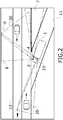
- the field of view (FOV) (8) of the driver (10) from the passenger's window and the field of view (FOV) (7) of the rear viewing device (2), that in this embodiment is a rear mirror of the commercial vehicle (1) located in the passenger side, are depicted in both figures.
- Figure 2 discloses the field of view (FOV) (6) of the image capturing unit (4).
- the rear viewing device (2) can be a rear mirror, as in the accompanying figures, or it can be a camera showing a rear view of the vehicle (1).
- the image capturing unit (4) of the vehicle imaging system object of the invention is configured for being located in the proximity of the passenger's rear mirror (2) location of the vehicle (1). For instance, it could be located directly on the support of the rear viewing device (2) or located on other element in the proximity of said support.
- the image capturing unit (4) is also configured for taking images of the surroundings of the lateral rear side of the vehicle (1) such that its field of view (6) extends until the limit of the field of view (7) of the rear mirror (2).
- Figures 1 and 2 show an embodiment in which the image capturing unit (4), specifically a camera, is also configured such that its field of view (6) extends until the limit of the field of view (8) in which a driver (10) could see the images surrounding the lateral rear side of the vehicle (1) through the passenger window of the vehicle (1).
- the image capturing unit (4) specifically a camera
- the optical axis (5) of the image capturing unit (4) is configured to be extended from 25o to 65o with respect to the vehicle (1) longitudinal axis. More preferably, is configured to be extended from 35o to 55o with respect to the vehicle (1) longitudinal axis as shown in the embodiment of the figures.
- the field of view (6) of the image capturing unit (4) is configured to be extended from 20o to 70o. More preferably, is configured to be extended from 30o to 60o in order not being bigger than 30-60o degrees so as to avoid deformation on the image as could be very dangerous to assess the speed of the vehicle (20) heading towards the driver's vehicle (1).
- the vehicle imaging system may additionally comprise a control unit configured to receive at least one parameter related to the movement of the vehicle (1) and also configured to send a signal to the display unit (9) to turn it on/off according to the received parameter.
- the vehicle imaging system could have communication with the vehicle (1) to get vehicle data.
- Said parameter could be the activation of the passenger's turn signal by the driver (10). Additionally it can be combined with a parameter related to the speed of the vehicle (1).
- the camera when the driver (10) activates the left turn signal, in a left-hand drive vehicle (1) or the right one in a right-hand drive vehicle (1), and the commercial vehicle (1) goes at less than, for example, 40 km/h, the camera turns ON and, for instance, the display (9) shows the captured image automatically. When the turn signal turns off (or few seconds later), the camera turns off and the display (9) returns to the initial image.
- the parameter is the activation of a switch configured for being activated by the driver (10).
- the driver (10) could activate the camera image manually through the display (9) interface or using a button in an accessible place.
- the image could be shown in the display (9) in full screen or like picture in picture (PinP) according the desired configuration.
- the thresholds of speed activation, the period of time that the image remains on the display (9) and the size of camera image (full screen or PinP) will be also predefined and could be adjustable or not by the driver (10).
- a control unit could also be configured for processing the captured image of the exterior environment of the vehicle (1) such that it is able to detect an object in movement in the captured image that could be potentially dangerous.
- Said control unit could be the same control unit as previously explained or another control unit, as an imaging processor unit.
- the control unit could be configured to send a signal to the display unit (9) to turn it on if an object in movement is detected in the captured image and therefore the captured image is shown automatically.
- the display unit (9) could also be configured to show a warning image.
- Said warning image can be a flashing square in the border of the image or a text in picture.
- the camera image taken by the image capturing unit (4) will show up in the display unit (9) but without a warning signal.
- the display unit (9) could be configured to display the captured image as if reflected in the display unit (9), i.e. processing the taken image so as to be shown as if the display unit (9) were a rear view mirror and hence the displayed image would be a specular image of the captured image.
- the display unit (9) could be configured to display the captured image as directly taken by the image capturing unit (4), without the previously indicated processing of the image to make it specular. From a practical way in an embodiment in which the image capturing unit (4) would be located in the passenger side, in the first alternative, i.e. the specular alternative, the image would have the part of the vehicle (1) in the left part and the road at the right part, and in the second alternative, the part of the vehicle would be in the right part of the image and the road in the left part.
- the vehicle (1) may have a camera unit as rear viewing device (2).
- the vehicle (1) may have two different displays, one for showing the image captured by the image capturing unit (4) according to the invention and another one for showing the image captured by the rear viewing device (2).
- the vehicle (1) may have one single display unit (9) for showing both captured images being the display unit (9) configured to display the captured image, as if reflected or as taken, and a captured image from the rear viewing device (2) when said rear viewing device (2) is a camera unit.
- the vehicle (1) comprises one single display unit (9) for displaying both captured images together
- the display unit (9) may be configured to display the image captured by the capturing unit (4) as a specular image and adjacent to it, the image taken by the rear viewing device (2), also as a specular image. Therefore, the display unit (9) would show, from left to right in an embodiment in which both the rear viewing device (2) and the capturing unit (4) would be located at the passenger side, the field of view (7) of the rear viewing device (2) that also may include a part of the vehicle (1), and adjacent to it, the field of view (6) of the capturing unit (4). Both displayed images may be separated by a vertical bar. As an alternative, both images could be displayed as a joined image by stitching the two images.
- the display unit (9) may be configured to display the image captured by the capturing unit (4) as directly taken by said capturing unit (4), without any processing to make it specular, and adjacent to it, the image taken by the rear viewing device (2).
- the display (9) would be configured to display both images separated by a vertical bar so as not to confuse the driver (10).
Landscapes
- Engineering & Computer Science (AREA)
- Multimedia (AREA)
- Mechanical Engineering (AREA)
- Physics & Mathematics (AREA)
- General Physics & Mathematics (AREA)
- Theoretical Computer Science (AREA)
- Closed-Circuit Television Systems (AREA)
Abstract
Description
- The present invention refers to a vehicle imaging system, more specifically, to a camera for commercial vehicles.
- The system is of the kind that displays images of the exterior environment of the vehicle taken by at least one camera mounted in the proximity of a rear viewing device located in a lateral side of the vehicle.
- It is known that the commercial vehicles are used to transport commercial goods and for that reason usually do not provide rear and/or lateral windows. This fact has the disadvantage that said lack of rear and/or lateral windows, either on the passenger side or on the driver side, increases the blind spot with respect to a conventional passenger car. There is thus a need to propose a solution for minimizing the blind spot on the lateral side in a commercial vehicle.
- There are also known vehicle imaging systems that comprise:
- an image capturing unit, for instance a camera, configured for taking images of the surroundings of the vehicle, having an optical axis and a field of view (FOV), and
- a display unit, for instance, a screen or a mirror usually located in the interior of the vehicle, connectable to the image capturing unit and configured to display the image taken by the capturing unit.
- The aforementioned display units can be located anywhere in the vehicle, for instance, on the dashboard, in a rear viewing device or in any other type of screen that is able to represent an image, mainly a digital image, as long as it is viewable by the driver.
- For the sake of clarity, the terms field of vision (FOV) and optical axis are herewith clarified. The field of view (FOV) is the captured area by the image capturing unit and the optical axis is an imaginary line along which there is some degree of rotational symmetry in an optical system such as a camera, said imaginary line defines the path along which light propagates through the optical system.
- The imaging system object of the invention is capable of providing a view of blind spot areas adjacent the commercial vehicle thus enhancing the driver's view for checking blind areas by viewing a display unit that provides the rear-view image of said blind spots.
- The image capturing unit of the vehicle imaging system is configured for being located in the proximity of a lateral rear viewing device, the image capturing unit configured for taking images of the surroundings of the lateral rear side of the vehicle, the image capturing unit being configured such that its field of view extends until the limit of the field of view of the rear viewing device.
- Therefore, the imaging system object of the invention collaborates in providing an expanded view of the rear end of the commercial vehicle, decreasing the blind-spot prevalent with respect to conventional rear-view mirrors.
- Additionally, it has to be observed that the camera is thus used as a complementary of the mirror, not for replacing the rear mirror. It has the advantage that no distortion is introduced into the captured image that could derive in misinterpretation of the speed of another vehicle due to deformation of the captured imaged related to a high field of view (FOV) of the image capturing unit.
- To complete the description and in order to provide for a better understanding of the invention, a set of drawings is provided. Said drawings form an integral part of the description and illustrate preferred embodiments of the invention. The drawings comprise the following figures.
-
FIG. 1 shows an overhead view of a left-hand drive commercial vehicle located in an entrance lane to a main road in which two adjacent vehicles are travelling in opposite directions, one coming from the rear part of the commercial vehicle and the other coming from the front of the commercial vehicle, both approaching the entrance lane. The fields of view (FOV) of the driver and of the rear viewing device of the commercial vehicle are depicted. -
FIG. 2 shows the same plan view offigure 1 adding the field of view (FOV) of an embodiment of the vehicle imaging system. -
FIG. 3 shows a schematic plan view of a left-hand vehicle with a vehicle imaging system, its optical axis and its field of view (FOV). -
FIG.4 shows an embodiment of a display unit located on a dashboard of a vehicle. -
Figures 1 and2 show the vehicle (1) located in an entrance lane (11) of a main road (12) in which two adjacent vehicles (20) are travelling in opposite directions, one coming from the rear part of the commercial vehicle (1) and the other coming from the front of the commercial vehicle (1), both approaching the entrance lane (11). The field of view (FOV) (8) of the driver (10) from the passenger's window and the field of view (FOV) (7) of the rear viewing device (2), that in this embodiment is a rear mirror of the commercial vehicle (1) located in the passenger side, are depicted in both figures.Figure 2 discloses the field of view (FOV) (6) of the image capturing unit (4). - The rear viewing device (2) can be a rear mirror, as in the accompanying figures, or it can be a camera showing a rear view of the vehicle (1).
- In the shown figures, the image capturing unit (4) of the vehicle imaging system object of the invention is configured for being located in the proximity of the passenger's rear mirror (2) location of the vehicle (1). For instance, it could be located directly on the support of the rear viewing device (2) or located on other element in the proximity of said support. The image capturing unit (4) is also configured for taking images of the surroundings of the lateral rear side of the vehicle (1) such that its field of view (6) extends until the limit of the field of view (7) of the rear mirror (2).
-
Figures 1 and2 show an embodiment in which the image capturing unit (4), specifically a camera, is also configured such that its field of view (6) extends until the limit of the field of view (8) in which a driver (10) could see the images surrounding the lateral rear side of the vehicle (1) through the passenger window of the vehicle (1). - The optical axis (5) of the image capturing unit (4) is configured to be extended from 25º to 65º with respect to the vehicle (1) longitudinal axis. More preferably, is configured to be extended from 35º to 55º with respect to the vehicle (1) longitudinal axis as shown in the embodiment of the figures.
- In turn, the field of view (6) of the image capturing unit (4) is configured to be extended from 20º to 70º. More preferably, is configured to be extended from 30º to 60º in order not being bigger than 30-60º degrees so as to avoid deformation on the image as could be very dangerous to assess the speed of the vehicle (20) heading towards the driver's vehicle (1).
- Therefore, as the embodiment depicted in
figures 1 and2 : - The field of view (FOV) (6) of the camera starts when the field of view (FOV) (7) of the rear mirror (2) ends in the forward side.
- The field of view (FOV) (6) of the camera finishes when the driver (10) could already see through the passenger window.
- The vehicle imaging system may additionally comprise a control unit configured to receive at least one parameter related to the movement of the vehicle (1) and also configured to send a signal to the display unit (9) to turn it on/off according to the received parameter. Thus, the vehicle imaging system could have communication with the vehicle (1) to get vehicle data. Said parameter could be the activation of the passenger's turn signal by the driver (10). Additionally it can be combined with a parameter related to the speed of the vehicle (1).
- In an embodiment, when the driver (10) activates the left turn signal, in a left-hand drive vehicle (1) or the right one in a right-hand drive vehicle (1), and the commercial vehicle (1) goes at less than, for example, 40 km/h, the camera turns ON and, for instance, the display (9) shows the captured image automatically. When the turn signal turns off (or few seconds later), the camera turns off and the display (9) returns to the initial image.
- Another option would be that the parameter is the activation of a switch configured for being activated by the driver (10). Thus the driver (10) could activate the camera image manually through the display (9) interface or using a button in an accessible place.
- The image could be shown in the display (9) in full screen or like picture in picture (PinP) according the desired configuration.
- The thresholds of speed activation, the period of time that the image remains on the display (9) and the size of camera image (full screen or PinP) will be also predefined and could be adjustable or not by the driver (10).
- As a complement to the above, a control unit could also be configured for processing the captured image of the exterior environment of the vehicle (1) such that it is able to detect an object in movement in the captured image that could be potentially dangerous. Said control unit could be the same control unit as previously explained or another control unit, as an imaging processor unit. Additionally, the control unit could be configured to send a signal to the display unit (9) to turn it on if an object in movement is detected in the captured image and therefore the captured image is shown automatically.
- The display unit (9) could also be configured to show a warning image. Said warning image can be a flashing square in the border of the image or a text in picture.
- Additionally, if the driver (10) activates the left turn signal (in a left-hand drive vehicle, the right one in a right-hand drive vehicle) and goes under a predefined speed threshold, the camera image taken by the image capturing unit (4) will show up in the display unit (9) but without a warning signal.
- The display unit (9) could be configured to display the captured image as if reflected in the display unit (9), i.e. processing the taken image so as to be shown as if the display unit (9) were a rear view mirror and hence the displayed image would be a specular image of the captured image. Alternatively, the display unit (9) could be configured to display the captured image as directly taken by the image capturing unit (4), without the previously indicated processing of the image to make it specular. From a practical way in an embodiment in which the image capturing unit (4) would be located in the passenger side, in the first alternative, i.e. the specular alternative, the image would have the part of the vehicle (1) in the left part and the road at the right part, and in the second alternative, the part of the vehicle would be in the right part of the image and the road in the left part.
- Additionally, it has to be taken into account that the vehicle (1) may have a camera unit as rear viewing device (2). In that case, the vehicle (1) may have two different displays, one for showing the image captured by the image capturing unit (4) according to the invention and another one for showing the image captured by the rear viewing device (2). As an alternative, the vehicle (1) may have one single display unit (9) for showing both captured images being the display unit (9) configured to display the captured image, as if reflected or as taken, and a captured image from the rear viewing device (2) when said rear viewing device (2) is a camera unit.
- In a first embodiment, i.e., the vehicle (1) comprises one single display unit (9) for displaying both captured images together, the display unit (9) may be configured to display the image captured by the capturing unit (4) as a specular image and adjacent to it, the image taken by the rear viewing device (2), also as a specular image. Therefore, the display unit (9) would show, from left to right in an embodiment in which both the rear viewing device (2) and the capturing unit (4) would be located at the passenger side, the field of view (7) of the rear viewing device (2) that also may include a part of the vehicle (1), and adjacent to it, the field of view (6) of the capturing unit (4). Both displayed images may be separated by a vertical bar. As an alternative, both images could be displayed as a joined image by stitching the two images.
- In a second embodiment, i.e., the vehicle (1) comprising one single display unit (9) for displaying both images together, the display unit (9) may be configured to display the image captured by the capturing unit (4) as directly taken by said capturing unit (4), without any processing to make it specular, and adjacent to it, the image taken by the rear viewing device (2). The display (9) would be configured to display both images separated by a vertical bar so as not to confuse the driver (10).
Claims (15)
- Vehicle imaging system, the vehicle (1) adapted to comprise a rear viewing device (2) configured to be located in a lateral side (3) of the vehicle (1), the vehicle imaging system comprising:- an image capturing unit (4) configured for taking images of the surroundings of the vehicle (1), the image capturing unit (4) having an optical axis (5) and a field of view (6), and- a display unit (9) configured for being located in the interior of the vehicle (1) and connectable to the image capturing unit (4) for displaying a captured image,characterised in that the image capturing unit (4) is configured for being located in the proximity of the rear viewing device (2) and configured for taking images of the surroundings of the lateral rear side of the vehicle (1), the image capturing unit (4) being configured such that its field of view (6) extends until the limit of the field of view (7) of the rear viewing device (2).
- Vehicle imaging system, according to claim 1, wherein the image capturing unit (4) is configured such that its field of view (6) extends until the limit of the field of view (8) in which a driver (10) could see the images surrounding the lateral rear side of the vehicle (1) through the lateral window of the vehicle (1) located in the lateral side (3) in which the image capturing unit (4) is located.
- Vehicle imaging system, according to any preceding claim, wherein the optical axis (5) of the image capturing unit (4) is configured to be extended from 25º to 65º with respect to the vehicle (1) longitudinal axis.
- Vehicle imaging system, according to claim 3, wherein the optical axis (5) of the image capturing unit (4) is configured to be extended from 35º to 55º with respect to the vehicle (1) longitudinal axis.
- Vehicle imaging system, according to any preceding claim, wherein the field of view (6) of the image capturing unit (4) is configured to be extended from 20º to 70º with respect to the vehicle (1) longitudinal axis.
- Vehicle imaging system, according to claim 5, wherein the field of view (6) of the image capturing unit (4) is configured to be extended from 30º to 60º with respect to the vehicle (1) longitudinal axis.
- Vehicle imaging system, according to any preceding claim, wherein it comprises a control unit configured to receive at least one parameter related to the movement of the vehicle (1) and also configured to send a signal to the display unit (9) to turn it on/off according to the received parameter.
- Vehicle imaging system, according to claim 7, wherein the received parameter is the activation of the turn signal by the driver (10).
- Vehicle imaging system, according to claim 8, wherein the received parameter is also the speed of the vehicle (1).
- Vehicle imaging system, according to claim 7, wherein the received parameter is the activation of a switch configured for being activated by the driver (10) for displaying the captured image.
- Vehicle imaging system, according to any claim 7 to 10, wherein the control unit is configured for processing the captured image of the surroundings of the lateral rear side of the vehicle (1) such that it is adapted to detect an object in movement in said captured image.
- Vehicle imaging system, according to claim 11, wherein the control unit is configured to send a signal to the display unit (9) to turn it on if an object in movement is detected in the captured image.
- Vehicle imaging system, according to any preceding claim, wherein the display unit (9) is configured to show a warning image.
- Vehicle imaging system, according to any preceding claim, wherein the display unit (9) is configured to display an specular image of the captured image or is configured to display the captured image as taken by the image capturing unit (4).
- Vehicle imaging system, according to claim 14, wherein the display unit (9) is further configured to display a captured image from the rear viewing device (2) when said rear viewing device (2) is a camera unit.
Priority Applications (4)
| Application Number | Priority Date | Filing Date | Title |
|---|---|---|---|
| EP17382794.0A EP3489087B1 (en) | 2017-11-24 | 2017-11-24 | Vehicle imaging system |
| US16/198,243 US10889245B2 (en) | 2017-11-24 | 2018-11-21 | Vehicle imaging system |
| JP2018219117A JP2019094055A (en) | 2017-11-24 | 2018-11-22 | Vehicle imaging system |
| CN201811404826.9A CN109835259B (en) | 2017-11-24 | 2018-11-23 | Vehicle imaging system |
Applications Claiming Priority (1)
| Application Number | Priority Date | Filing Date | Title |
|---|---|---|---|
| EP17382794.0A EP3489087B1 (en) | 2017-11-24 | 2017-11-24 | Vehicle imaging system |
Publications (2)
| Publication Number | Publication Date |
|---|---|
| EP3489087A1 true EP3489087A1 (en) | 2019-05-29 |
| EP3489087B1 EP3489087B1 (en) | 2021-05-05 |
Family
ID=60484319
Family Applications (1)
| Application Number | Title | Priority Date | Filing Date |
|---|---|---|---|
| EP17382794.0A Active EP3489087B1 (en) | 2017-11-24 | 2017-11-24 | Vehicle imaging system |
Country Status (4)
| Country | Link |
|---|---|
| US (1) | US10889245B2 (en) |
| EP (1) | EP3489087B1 (en) |
| JP (1) | JP2019094055A (en) |
| CN (1) | CN109835259B (en) |
Families Citing this family (1)
| Publication number | Priority date | Publication date | Assignee | Title |
|---|---|---|---|---|
| WO2020169693A1 (en) | 2019-02-19 | 2020-08-27 | Orlaco Products B.V. | Mirror replacement system with dynamic stitching |
Citations (6)
| Publication number | Priority date | Publication date | Assignee | Title |
|---|---|---|---|---|
| EP1018839A2 (en) * | 1999-01-08 | 2000-07-12 | Volkswagen Aktiengesellschaft | Method and apparatus for inspecting the rear observation space of a vehicle |
| JP2001084500A (en) * | 1999-09-14 | 2001-03-30 | Sumitomo Electric Ind Ltd | Travel support device for moving objects |
| US20060125919A1 (en) * | 2004-09-30 | 2006-06-15 | Joseph Camilleri | Vision system for vehicle |
| US20140055616A1 (en) * | 2012-08-27 | 2014-02-27 | DigitalOptics Corporation Europe Limited | Rearview Imaging Systems for Vehicle |
| US20150203033A1 (en) * | 2012-08-17 | 2015-07-23 | Honda Motor Co., Ltd. | Driving assistance device |
| WO2017041886A1 (en) * | 2015-09-10 | 2017-03-16 | Audi Ag | Blind spot surveillance in a vehicle |
Family Cites Families (5)
| Publication number | Priority date | Publication date | Assignee | Title |
|---|---|---|---|---|
| US8694195B2 (en) * | 2007-12-04 | 2014-04-08 | Volkswagen Ag | Motor vehicle having a wheel-view camera and method for controlling a wheel-view camera system |
| EP2473871B1 (en) * | 2009-09-01 | 2015-03-11 | Magna Mirrors Of America, Inc. | Imaging and display system for vehicle |
| US9697735B2 (en) * | 2011-12-15 | 2017-07-04 | Panasonic Intellectual Property Management Co., Ltd. | Drive assistance device |
| US9676336B2 (en) * | 2013-06-25 | 2017-06-13 | Magna Mirrors Of America, Inc. | Exterior rearview mirror assembly for vehicle |
| US10486599B2 (en) * | 2015-07-17 | 2019-11-26 | Magna Mirrors Of America, Inc. | Rearview vision system for vehicle |
-
2017
- 2017-11-24 EP EP17382794.0A patent/EP3489087B1/en active Active
-
2018
- 2018-11-21 US US16/198,243 patent/US10889245B2/en active Active
- 2018-11-22 JP JP2018219117A patent/JP2019094055A/en active Pending
- 2018-11-23 CN CN201811404826.9A patent/CN109835259B/en active Active
Patent Citations (6)
| Publication number | Priority date | Publication date | Assignee | Title |
|---|---|---|---|---|
| EP1018839A2 (en) * | 1999-01-08 | 2000-07-12 | Volkswagen Aktiengesellschaft | Method and apparatus for inspecting the rear observation space of a vehicle |
| JP2001084500A (en) * | 1999-09-14 | 2001-03-30 | Sumitomo Electric Ind Ltd | Travel support device for moving objects |
| US20060125919A1 (en) * | 2004-09-30 | 2006-06-15 | Joseph Camilleri | Vision system for vehicle |
| US20150203033A1 (en) * | 2012-08-17 | 2015-07-23 | Honda Motor Co., Ltd. | Driving assistance device |
| US20140055616A1 (en) * | 2012-08-27 | 2014-02-27 | DigitalOptics Corporation Europe Limited | Rearview Imaging Systems for Vehicle |
| WO2017041886A1 (en) * | 2015-09-10 | 2017-03-16 | Audi Ag | Blind spot surveillance in a vehicle |
Also Published As
| Publication number | Publication date |
|---|---|
| JP2019094055A (en) | 2019-06-20 |
| CN109835259B (en) | 2024-09-13 |
| US10889245B2 (en) | 2021-01-12 |
| US20190161011A1 (en) | 2019-05-30 |
| CN109835259A (en) | 2019-06-04 |
| EP3489087B1 (en) | 2021-05-05 |
Similar Documents
| Publication | Publication Date | Title |
|---|---|---|
| US10029621B2 (en) | Rear view camera system using rear view mirror location | |
| US10293750B2 (en) | Digital display system with a front-facing camera and rear digital display | |
| US9661280B2 (en) | Rearview obstruction camera system and associated method | |
| US10457209B2 (en) | Vehicle vision system with multi-paned view | |
| US20130155236A1 (en) | Camera-mirror system for motor vehicle | |
| US11584299B2 (en) | Driver-assisting system for an industrial vehicle | |
| US10988144B2 (en) | Driver assistance system and method for a motor vehicle for displaying an augmented reality | |
| KR101552444B1 (en) | Visual system | |
| US20170043719A1 (en) | Heads up display for side mirror display | |
| WO2017204203A1 (en) | Vehicle monitor system | |
| US7057500B1 (en) | Rear view monitoring system for motor vehicles | |
| JP2018182646A (en) | Image display device | |
| EP3166307B1 (en) | Capturing device for a motor vehicle, driver assistance system as well as motor vehicle | |
| JP6639437B2 (en) | Information presentation device | |
| US20080068455A1 (en) | Rear facing viewing system for large vehicles | |
| US20160129838A1 (en) | Wide angle rear and side view monitor | |
| US10889245B2 (en) | Vehicle imaging system | |
| KR102061210B1 (en) | Side front blind area display apparatus for vehicle and the method thereof | |
| GB2397189A (en) | Forward looking road monitoring system for vehicles | |
| CN106143303A (en) | A car driving imaging technology | |
| JP6021888B2 (en) | Image control apparatus and image control system using the same | |
| JP6878109B2 (en) | Image display device | |
| CN107933429A (en) | Image adjusting method and system, the Streaming Media rearview mirror of Streaming Media rearview mirror | |
| JP2019110390A (en) | Vehicle periphery monitoring device | |
| KR100971453B1 (en) | Car rearview system |
Legal Events
| Date | Code | Title | Description |
|---|---|---|---|
| PUAI | Public reference made under article 153(3) epc to a published international application that has entered the european phase |
Free format text: ORIGINAL CODE: 0009012 |
|
| STAA | Information on the status of an ep patent application or granted ep patent |
Free format text: STATUS: THE APPLICATION HAS BEEN PUBLISHED |
|
| AK | Designated contracting states |
Kind code of ref document: A1 Designated state(s): AL AT BE BG CH CY CZ DE DK EE ES FI FR GB GR HR HU IE IS IT LI LT LU LV MC MK MT NL NO PL PT RO RS SE SI SK SM TR |
|
| AX | Request for extension of the european patent |
Extension state: BA ME |
|
| STAA | Information on the status of an ep patent application or granted ep patent |
Free format text: STATUS: REQUEST FOR EXAMINATION WAS MADE |
|
| 17P | Request for examination filed |
Effective date: 20191129 |
|
| RBV | Designated contracting states (corrected) |
Designated state(s): AL AT BE BG CH CY CZ DE DK EE ES FI FR GB GR HR HU IE IS IT LI LT LU LV MC MK MT NL NO PL PT RO RS SE SI SK SM TR |
|
| STAA | Information on the status of an ep patent application or granted ep patent |
Free format text: STATUS: EXAMINATION IS IN PROGRESS |
|
| 17Q | First examination report despatched |
Effective date: 20200121 |
|
| GRAP | Despatch of communication of intention to grant a patent |
Free format text: ORIGINAL CODE: EPIDOSNIGR1 |
|
| STAA | Information on the status of an ep patent application or granted ep patent |
Free format text: STATUS: GRANT OF PATENT IS INTENDED |
|
| INTG | Intention to grant announced |
Effective date: 20201126 |
|
| GRAS | Grant fee paid |
Free format text: ORIGINAL CODE: EPIDOSNIGR3 |
|
| GRAA | (expected) grant |
Free format text: ORIGINAL CODE: 0009210 |
|
| STAA | Information on the status of an ep patent application or granted ep patent |
Free format text: STATUS: THE PATENT HAS BEEN GRANTED |
|
| AK | Designated contracting states |
Kind code of ref document: B1 Designated state(s): AL AT BE BG CH CY CZ DE DK EE ES FI FR GB GR HR HU IE IS IT LI LT LU LV MC MK MT NL NO PL PT RO RS SE SI SK SM TR |
|
| REG | Reference to a national code |
Ref country code: GB Ref legal event code: FG4D |
|
| REG | Reference to a national code |
Ref country code: CH Ref legal event code: EP |
|
| REG | Reference to a national code |
Ref country code: AT Ref legal event code: REF Ref document number: 1389425 Country of ref document: AT Kind code of ref document: T Effective date: 20210515 |
|
| REG | Reference to a national code |
Ref country code: IE Ref legal event code: FG4D |
|
| REG | Reference to a national code |
Ref country code: DE Ref legal event code: R096 Ref document number: 602017038000 Country of ref document: DE |
|
| REG | Reference to a national code |
Ref country code: LT Ref legal event code: MG9D |
|
| REG | Reference to a national code |
Ref country code: AT Ref legal event code: MK05 Ref document number: 1389425 Country of ref document: AT Kind code of ref document: T Effective date: 20210505 |
|
| PG25 | Lapsed in a contracting state [announced via postgrant information from national office to epo] |
Ref country code: LT Free format text: LAPSE BECAUSE OF FAILURE TO SUBMIT A TRANSLATION OF THE DESCRIPTION OR TO PAY THE FEE WITHIN THE PRESCRIBED TIME-LIMIT Effective date: 20210505 Ref country code: FI Free format text: LAPSE BECAUSE OF FAILURE TO SUBMIT A TRANSLATION OF THE DESCRIPTION OR TO PAY THE FEE WITHIN THE PRESCRIBED TIME-LIMIT Effective date: 20210505 Ref country code: BG Free format text: LAPSE BECAUSE OF FAILURE TO SUBMIT A TRANSLATION OF THE DESCRIPTION OR TO PAY THE FEE WITHIN THE PRESCRIBED TIME-LIMIT Effective date: 20210805 Ref country code: AT Free format text: LAPSE BECAUSE OF FAILURE TO SUBMIT A TRANSLATION OF THE DESCRIPTION OR TO PAY THE FEE WITHIN THE PRESCRIBED TIME-LIMIT Effective date: 20210505 Ref country code: HR Free format text: LAPSE BECAUSE OF FAILURE TO SUBMIT A TRANSLATION OF THE DESCRIPTION OR TO PAY THE FEE WITHIN THE PRESCRIBED TIME-LIMIT Effective date: 20210505 |
|
| PG25 | Lapsed in a contracting state [announced via postgrant information from national office to epo] |
Ref country code: LV Free format text: LAPSE BECAUSE OF FAILURE TO SUBMIT A TRANSLATION OF THE DESCRIPTION OR TO PAY THE FEE WITHIN THE PRESCRIBED TIME-LIMIT Effective date: 20210505 Ref country code: IS Free format text: LAPSE BECAUSE OF FAILURE TO SUBMIT A TRANSLATION OF THE DESCRIPTION OR TO PAY THE FEE WITHIN THE PRESCRIBED TIME-LIMIT Effective date: 20210905 Ref country code: GR Free format text: LAPSE BECAUSE OF FAILURE TO SUBMIT A TRANSLATION OF THE DESCRIPTION OR TO PAY THE FEE WITHIN THE PRESCRIBED TIME-LIMIT Effective date: 20210806 Ref country code: SE Free format text: LAPSE BECAUSE OF FAILURE TO SUBMIT A TRANSLATION OF THE DESCRIPTION OR TO PAY THE FEE WITHIN THE PRESCRIBED TIME-LIMIT Effective date: 20210505 Ref country code: RS Free format text: LAPSE BECAUSE OF FAILURE TO SUBMIT A TRANSLATION OF THE DESCRIPTION OR TO PAY THE FEE WITHIN THE PRESCRIBED TIME-LIMIT Effective date: 20210505 Ref country code: NO Free format text: LAPSE BECAUSE OF FAILURE TO SUBMIT A TRANSLATION OF THE DESCRIPTION OR TO PAY THE FEE WITHIN THE PRESCRIBED TIME-LIMIT Effective date: 20210805 Ref country code: PL Free format text: LAPSE BECAUSE OF FAILURE TO SUBMIT A TRANSLATION OF THE DESCRIPTION OR TO PAY THE FEE WITHIN THE PRESCRIBED TIME-LIMIT Effective date: 20210505 Ref country code: PT Free format text: LAPSE BECAUSE OF FAILURE TO SUBMIT A TRANSLATION OF THE DESCRIPTION OR TO PAY THE FEE WITHIN THE PRESCRIBED TIME-LIMIT Effective date: 20210906 |
|
| REG | Reference to a national code |
Ref country code: NL Ref legal event code: MP Effective date: 20210505 |
|
| PG25 | Lapsed in a contracting state [announced via postgrant information from national office to epo] |
Ref country code: NL Free format text: LAPSE BECAUSE OF FAILURE TO SUBMIT A TRANSLATION OF THE DESCRIPTION OR TO PAY THE FEE WITHIN THE PRESCRIBED TIME-LIMIT Effective date: 20210505 |
|
| PG25 | Lapsed in a contracting state [announced via postgrant information from national office to epo] |
Ref country code: SK Free format text: LAPSE BECAUSE OF FAILURE TO SUBMIT A TRANSLATION OF THE DESCRIPTION OR TO PAY THE FEE WITHIN THE PRESCRIBED TIME-LIMIT Effective date: 20210505 Ref country code: SM Free format text: LAPSE BECAUSE OF FAILURE TO SUBMIT A TRANSLATION OF THE DESCRIPTION OR TO PAY THE FEE WITHIN THE PRESCRIBED TIME-LIMIT Effective date: 20210505 Ref country code: CZ Free format text: LAPSE BECAUSE OF FAILURE TO SUBMIT A TRANSLATION OF THE DESCRIPTION OR TO PAY THE FEE WITHIN THE PRESCRIBED TIME-LIMIT Effective date: 20210505 Ref country code: EE Free format text: LAPSE BECAUSE OF FAILURE TO SUBMIT A TRANSLATION OF THE DESCRIPTION OR TO PAY THE FEE WITHIN THE PRESCRIBED TIME-LIMIT Effective date: 20210505 Ref country code: DK Free format text: LAPSE BECAUSE OF FAILURE TO SUBMIT A TRANSLATION OF THE DESCRIPTION OR TO PAY THE FEE WITHIN THE PRESCRIBED TIME-LIMIT Effective date: 20210505 Ref country code: RO Free format text: LAPSE BECAUSE OF FAILURE TO SUBMIT A TRANSLATION OF THE DESCRIPTION OR TO PAY THE FEE WITHIN THE PRESCRIBED TIME-LIMIT Effective date: 20210505 Ref country code: ES Free format text: LAPSE BECAUSE OF FAILURE TO SUBMIT A TRANSLATION OF THE DESCRIPTION OR TO PAY THE FEE WITHIN THE PRESCRIBED TIME-LIMIT Effective date: 20210505 |
|
| REG | Reference to a national code |
Ref country code: DE Ref legal event code: R097 Ref document number: 602017038000 Country of ref document: DE |
|
| PLBE | No opposition filed within time limit |
Free format text: ORIGINAL CODE: 0009261 |
|
| STAA | Information on the status of an ep patent application or granted ep patent |
Free format text: STATUS: NO OPPOSITION FILED WITHIN TIME LIMIT |
|
| 26N | No opposition filed |
Effective date: 20220208 |
|
| PG25 | Lapsed in a contracting state [announced via postgrant information from national office to epo] |
Ref country code: IS Free format text: LAPSE BECAUSE OF FAILURE TO SUBMIT A TRANSLATION OF THE DESCRIPTION OR TO PAY THE FEE WITHIN THE PRESCRIBED TIME-LIMIT Effective date: 20210905 Ref country code: AL Free format text: LAPSE BECAUSE OF FAILURE TO SUBMIT A TRANSLATION OF THE DESCRIPTION OR TO PAY THE FEE WITHIN THE PRESCRIBED TIME-LIMIT Effective date: 20210505 |
|
| PG25 | Lapsed in a contracting state [announced via postgrant information from national office to epo] |
Ref country code: MC Free format text: LAPSE BECAUSE OF FAILURE TO SUBMIT A TRANSLATION OF THE DESCRIPTION OR TO PAY THE FEE WITHIN THE PRESCRIBED TIME-LIMIT Effective date: 20210505 |
|
| REG | Reference to a national code |
Ref country code: CH Ref legal event code: PL |
|
| GBPC | Gb: european patent ceased through non-payment of renewal fee |
Effective date: 20211124 |
|
| PG25 | Lapsed in a contracting state [announced via postgrant information from national office to epo] |
Ref country code: LU Free format text: LAPSE BECAUSE OF NON-PAYMENT OF DUE FEES Effective date: 20211124 Ref country code: IT Free format text: LAPSE BECAUSE OF FAILURE TO SUBMIT A TRANSLATION OF THE DESCRIPTION OR TO PAY THE FEE WITHIN THE PRESCRIBED TIME-LIMIT Effective date: 20210505 Ref country code: BE Free format text: LAPSE BECAUSE OF NON-PAYMENT OF DUE FEES Effective date: 20211130 |
|
| REG | Reference to a national code |
Ref country code: BE Ref legal event code: MM Effective date: 20211130 |
|
| PG25 | Lapsed in a contracting state [announced via postgrant information from national office to epo] |
Ref country code: LI Free format text: LAPSE BECAUSE OF NON-PAYMENT OF DUE FEES Effective date: 20211130 Ref country code: CH Free format text: LAPSE BECAUSE OF NON-PAYMENT OF DUE FEES Effective date: 20211130 |
|
| PG25 | Lapsed in a contracting state [announced via postgrant information from national office to epo] |
Ref country code: IE Free format text: LAPSE BECAUSE OF NON-PAYMENT OF DUE FEES Effective date: 20211124 Ref country code: GB Free format text: LAPSE BECAUSE OF NON-PAYMENT OF DUE FEES Effective date: 20211124 |
|
| PG25 | Lapsed in a contracting state [announced via postgrant information from national office to epo] |
Ref country code: FR Free format text: LAPSE BECAUSE OF NON-PAYMENT OF DUE FEES Effective date: 20211130 |
|
| PG25 | Lapsed in a contracting state [announced via postgrant information from national office to epo] |
Ref country code: CY Free format text: LAPSE BECAUSE OF FAILURE TO SUBMIT A TRANSLATION OF THE DESCRIPTION OR TO PAY THE FEE WITHIN THE PRESCRIBED TIME-LIMIT Effective date: 20210505 |
|
| PG25 | Lapsed in a contracting state [announced via postgrant information from national office to epo] |
Ref country code: HU Free format text: LAPSE BECAUSE OF FAILURE TO SUBMIT A TRANSLATION OF THE DESCRIPTION OR TO PAY THE FEE WITHIN THE PRESCRIBED TIME-LIMIT; INVALID AB INITIO Effective date: 20171124 |
|
| PG25 | Lapsed in a contracting state [announced via postgrant information from national office to epo] |
Ref country code: MK Free format text: LAPSE BECAUSE OF FAILURE TO SUBMIT A TRANSLATION OF THE DESCRIPTION OR TO PAY THE FEE WITHIN THE PRESCRIBED TIME-LIMIT Effective date: 20210505 |
|
| PG25 | Lapsed in a contracting state [announced via postgrant information from national office to epo] |
Ref country code: MT Free format text: LAPSE BECAUSE OF FAILURE TO SUBMIT A TRANSLATION OF THE DESCRIPTION OR TO PAY THE FEE WITHIN THE PRESCRIBED TIME-LIMIT Effective date: 20210505 |
|
| PG25 | Lapsed in a contracting state [announced via postgrant information from national office to epo] |
Ref country code: TR Free format text: LAPSE BECAUSE OF FAILURE TO SUBMIT A TRANSLATION OF THE DESCRIPTION OR TO PAY THE FEE WITHIN THE PRESCRIBED TIME-LIMIT Effective date: 20210505 |
|
| PGFP | Annual fee paid to national office [announced via postgrant information from national office to epo] |
Ref country code: DE Payment date: 20251128 Year of fee payment: 9 |