EP3489065B1 - Energy generation system for a vehicle - Google Patents
Energy generation system for a vehicle Download PDFInfo
- Publication number
- EP3489065B1 EP3489065B1 EP18208982.1A EP18208982A EP3489065B1 EP 3489065 B1 EP3489065 B1 EP 3489065B1 EP 18208982 A EP18208982 A EP 18208982A EP 3489065 B1 EP3489065 B1 EP 3489065B1
- Authority
- EP
- European Patent Office
- Prior art keywords
- alternators
- transmission shaft
- vehicle
- generation system
- engine
- Prior art date
- Legal status (The legal status is an assumption and is not a legal conclusion. Google has not performed a legal analysis and makes no representation as to the accuracy of the status listed.)
- Active
Links
Images

Classifications
-
- B—PERFORMING OPERATIONS; TRANSPORTING
- B60—VEHICLES IN GENERAL
- B60K—ARRANGEMENT OR MOUNTING OF PROPULSION UNITS OR OF TRANSMISSIONS IN VEHICLES; ARRANGEMENT OR MOUNTING OF PLURAL DIVERSE PRIME-MOVERS IN VEHICLES; AUXILIARY DRIVES FOR VEHICLES; INSTRUMENTATION OR DASHBOARDS FOR VEHICLES; ARRANGEMENTS IN CONNECTION WITH COOLING, AIR INTAKE, GAS EXHAUST OR FUEL SUPPLY OF PROPULSION UNITS IN VEHICLES
- B60K25/00—Auxiliary drives
- B60K25/02—Auxiliary drives directly from an engine shaft
-
- B—PERFORMING OPERATIONS; TRANSPORTING
- B60—VEHICLES IN GENERAL
- B60L—PROPULSION OF ELECTRICALLY-PROPELLED VEHICLES; SUPPLYING ELECTRIC POWER FOR AUXILIARY EQUIPMENT OF ELECTRICALLY-PROPELLED VEHICLES; ELECTRODYNAMIC BRAKE SYSTEMS FOR VEHICLES IN GENERAL; MAGNETIC SUSPENSION OR LEVITATION FOR VEHICLES; MONITORING OPERATING VARIABLES OF ELECTRICALLY-PROPELLED VEHICLES; ELECTRIC SAFETY DEVICES FOR ELECTRICALLY-PROPELLED VEHICLES
- B60L50/00—Electric propulsion with power supplied within the vehicle
- B60L50/10—Electric propulsion with power supplied within the vehicle using propulsion power supplied by engine-driven generators, e.g. generators driven by combustion engines
- B60L50/16—Electric propulsion with power supplied within the vehicle using propulsion power supplied by engine-driven generators, e.g. generators driven by combustion engines with provision for separate direct mechanical propulsion
-
- B—PERFORMING OPERATIONS; TRANSPORTING
- B60—VEHICLES IN GENERAL
- B60Y—INDEXING SCHEME RELATING TO ASPECTS CROSS-CUTTING VEHICLE TECHNOLOGY
- B60Y2200/00—Type of vehicle
- B60Y2200/10—Road Vehicles
- B60Y2200/14—Trucks; Load vehicles, Busses
- B60Y2200/143—Busses
Definitions
- the present invention concerns an energy generation system, particularly an energy generation system for a public passenger transport vehicle.
- At least one alternator is normally used, which is arranged near the vehicle's engine and which converts a portion of the rotational energy of the crankshaft into electrical energy.
- Alternators occupy a significant amount of space and thus, by increasing their number and/or power, overcrowding around the engine has increased. This reduces the room available for other components.
- a vehicle normally has two alternators which are positioned in opposition with respect to the vertical axis of symmetry of the engine in order to balance the forces on the crankshaft. If a vehicle has three alternators, two are positioned on one side of the engine and the remaining one on the opposite side; the ratio of the weights supported by the engine is thus destabilised because the forces acting on one side and on the other are unequal.
- the alternators since the alternator pulley must be mechanically coupled with the crankshaft, the alternators must be positioned close to the engine. However, the temperature is very high (90-105 °C) in the vicinity of the engine as a result of the combustion which occurs inside the engine; the ideal efficiency of the alternators is at 25 °C and becomes much worse at high temperatures.
- US2009/000836A1 A discloses a drive assembly which can apply a pure torque to a driven member while allowing for limited motion of the driven member in the radial direction.
- This drive assembly is particularly suitable for converting an Internal Combustion (IC) vehicle to an IC-electric hybrid vehicle comprising installation of two electric motors coupled to a drive shaft of the vehicle via the drive of this invention such that the electric motors can provide some or all of the mechanical power required to propel the vehicle while accepting some relative motion between the existing vehicle drive shafts and the chassis and imposing minimal radial force on the drive shaft.
- IC Internal Combustion
- the invention aims to solve the above-mentioned problems in a simple and cost-effective way.
- the present description refers to a bus, however it could be applied to any vehicle, for example a truck or lorry.
- Figure 1 schematically illustrates the frame 3 of a public passenger transport vehicle 1, essentially comprising at least one pair of driving wheels 4, preferably rear wheels, supported by the frame 3 and free to roll relative to the latter.
- the vehicle 1 further comprises an engine 6 mechanically coupled to the wheels 4 in order to provide them with drive torque by means of a transmission shaft 8, in a known manner.
- the vehicle 1 comprises a generation system 10 configured to produce electrical energy by using the rotational energy of the transmission shaft 8.
- the generation system 10 is directly coupled to the transmission shaft 8 downstream of the engine 6 and upstream of the wheels 4, more precisely it is positioned outside the engine compartment along the axis of the transmission shaft 8.
- the generation system 10 comprises at least two alternators 11 attached to the frame 3 of the vehicle 1 whose respective pulleys are mechanically coupled with the transmission shaft 8.
- the at least two alternators 11 are beneficially attached to the opposite sides with respect to the transmission shaft 8, more precisely symmetrically with respect to the axis of the transmission shaft 8 in order to minimise the tilting moments acting on the transmission shaft 8 due to the mechanical coupling with the at least two alternators 11.
- the number of alternators 11 is a multiple of two. In the present description, there are two alternators.
- the at least two alternators 11 are each mechanically coupled to the transmission shaft 8 by means of a coupling system with a fixed transmission ratio.
- the aforesaid mechanical coupling is preferably a belt drive 12.
- the belt drive 12 is a toothed belt drive implemented between the pulley of the alternators 11 and a sleeve 14 attached around the shaft 8 and of a diameter such that it establishes a pre-set transmission ratio with the pulley of the alternators 11.
- the alternators 11 are preferably attached to the frame by a bracket 13.
- the generation system 10, or alternatively the alternators 11, may comprise a cover (not shown) configured to prevent contamination of the alternators 11 and the belt drive 12 from, for example, water or dirt.
- the efficiency of the alternators 11 is improved since their working temperature is lower with respect to the temperature in the vicinity of the engine 6. As a result, lower/standard power alternators can be used which take up less room.
- alternators are installed downstream of the engine 6 and upstream of the wheels 4, i.e. downstream of the gearbox retarder, it is possible to recover more energy at idle. Indeed, the torque is that which comes directly from the wheels 4. Heat losses due to the gearbox retarder as well as mechanical losses of the gearbox have no effect on the amount of energy recovered by the system of alternators 11.
- vehicle 1 comprising an energy generation system 10 according to the present invention may be subject to modifications and variations without thereby departing from the protective scope defined by the Claims.
- alternators 11 there may be four or six alternators 11 positioned symmetrically with respect to the axis of the transmission shaft 8.
Landscapes
- Engineering & Computer Science (AREA)
- Chemical & Material Sciences (AREA)
- Combustion & Propulsion (AREA)
- Transportation (AREA)
- Mechanical Engineering (AREA)
- Connection Of Motors, Electrical Generators, Mechanical Devices, And The Like (AREA)
- Control Of Eletrric Generators (AREA)
Description
- The present invention concerns an energy generation system, particularly an energy generation system for a public passenger transport vehicle.
- Electronic devices are increasingly present on vehicles and the demand for generating electrical power to power them is increasing as a result.
- In order to generate said electrical current, at least one alternator is normally used, which is arranged near the vehicle's engine and which converts a portion of the rotational energy of the crankshaft into electrical energy.
- Over time, in order to increase the said energy generation, the number of alternators has been increased so as to be up to three alternators per vehicle. Since it was insufficient, the power of each individual alternator has been increased from 90 A to 120-150 A.
- Several problems have emerged.
- Alternators occupy a significant amount of space and thus, by increasing their number and/or power, overcrowding around the engine has increased. This reduces the room available for other components.
- In addition, a vehicle normally has two alternators which are positioned in opposition with respect to the vertical axis of symmetry of the engine in order to balance the forces on the crankshaft. If a vehicle has three alternators, two are positioned on one side of the engine and the remaining one on the opposite side; the ratio of the weights supported by the engine is thus destabilised because the forces acting on one side and on the other are unequal.
- In addition, since the alternator pulley must be mechanically coupled with the crankshaft, the alternators must be positioned close to the engine. However, the temperature is very high (90-105 °C) in the vicinity of the engine as a result of the combustion which occurs inside the engine; the ideal efficiency of the alternators is at 25 °C and becomes much worse at high temperatures.
- The increase in power required to compensate for the loss of efficiency due to high temperatures requires the use of cables with a large cross-section and oversized belts to transmit the necessary torque.
- Finally, energy recovery during deceleration phases can only be achieved with idler pulley systems (BSG tensioners), which also take up a lot of space around the engine.
- Examples of known energy recovery arrangements are disclosed for instance in documents
US2009/095549 A1 ,GB2543043 A US4222450A ,GB2462325 A US2004/262062 A1 orUS2006/0030450 A1 . -
US2009/000836A1 A discloses a drive assembly which can apply a pure torque to a driven member while allowing for limited motion of the driven member in the radial direction. This drive assembly is particularly suitable for converting an Internal Combustion (IC) vehicle to an IC-electric hybrid vehicle comprising installation of two electric motors coupled to a drive shaft of the vehicle via the drive of this invention such that the electric motors can provide some or all of the mechanical power required to propel the vehicle while accepting some relative motion between the existing vehicle drive shafts and the chassis and imposing minimal radial force on the drive shaft. - It is thus still necessary to improve energy generation systems in order to increase the electrical energy produced without however increasing the space requirements in vehicles.
- The invention aims to solve the above-mentioned problems in a simple and cost-effective way.
- The above-mentioned objects are achieved by an electrical power generation system according to
Claim 1. - Other characteristics and benefits of the invention will become apparent from the following non-limiting description, provided for illustrative purposes, with reference to the attached drawings wherein:
-
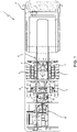
Figure 1 is a plan view, with parts removed for clarity, of a vehicle comprising a system according to the invention; -
Figure 2 is a cross-section view, with parts removed for clarity, of the system according to the invention; and -
Figure 3 is a plan view, with parts removed for clarity, of the system ofFigure 2 . - The present description refers to a bus, however it could be applied to any vehicle, for example a truck or lorry.
-
Figure 1 schematically illustrates theframe 3 of a publicpassenger transport vehicle 1, essentially comprising at least one pair ofdriving wheels 4, preferably rear wheels, supported by theframe 3 and free to roll relative to the latter. Thevehicle 1 further comprises anengine 6 mechanically coupled to thewheels 4 in order to provide them with drive torque by means of atransmission shaft 8, in a known manner. - According to the present invention, the
vehicle 1 comprises ageneration system 10 configured to produce electrical energy by using the rotational energy of thetransmission shaft 8. Thegeneration system 10 is directly coupled to thetransmission shaft 8 downstream of theengine 6 and upstream of thewheels 4, more precisely it is positioned outside the engine compartment along the axis of thetransmission shaft 8. - In more detail (
Figures 2 and 3 ), thegeneration system 10 comprises at least twoalternators 11 attached to theframe 3 of thevehicle 1 whose respective pulleys are mechanically coupled with thetransmission shaft 8. - The at least two
alternators 11 are beneficially attached to the opposite sides with respect to thetransmission shaft 8, more precisely symmetrically with respect to the axis of thetransmission shaft 8 in order to minimise the tilting moments acting on thetransmission shaft 8 due to the mechanical coupling with the at least twoalternators 11. - For this reason, the number of
alternators 11 is a multiple of two. In the present description, there are two alternators. - The at least two
alternators 11 are each mechanically coupled to thetransmission shaft 8 by means of a coupling system with a fixed transmission ratio. - The aforesaid mechanical coupling is preferably a
belt drive 12. Advantageously, thebelt drive 12 is a toothed belt drive implemented between the pulley of thealternators 11 and asleeve 14 attached around theshaft 8 and of a diameter such that it establishes a pre-set transmission ratio with the pulley of thealternators 11. - The
alternators 11 are preferably attached to the frame by abracket 13. - The
generation system 10, or alternatively thealternators 11, may comprise a cover (not shown) configured to prevent contamination of thealternators 11 and the belt drive 12 from, for example, water or dirt. - From the above, the benefits of a
vehicle 1 with anenergy generation system 10 according to the present invention are very clear. - Since the
alternators 11 are no longer attached to the housing of theengine 6, there is more space in the engine compartment for the other auxiliary devices to be installed. - Furthermore, the problem of destabilising the ratio of the weights supported by the engine no longer exists.
- The efficiency of the
alternators 11 is improved since their working temperature is lower with respect to the temperature in the vicinity of theengine 6. As a result, lower/standard power alternators can be used which take up less room. - By using standard power alternators, the cable cross-section and belt size can be reduced.
- Furthermore, since the alternators are installed downstream of the
engine 6 and upstream of thewheels 4, i.e. downstream of the gearbox retarder, it is possible to recover more energy at idle. Indeed, the torque is that which comes directly from thewheels 4. Heat losses due to the gearbox retarder as well as mechanical losses of the gearbox have no effect on the amount of energy recovered by the system ofalternators 11. - Finally, it is clear that the
vehicle 1 comprising anenergy generation system 10 according to the present invention may be subject to modifications and variations without thereby departing from the protective scope defined by the Claims. - For example, there may be four or six
alternators 11 positioned symmetrically with respect to the axis of thetransmission shaft 8.
Claims (6)
- A vehicle (1) comprising an engine (6), a frame (3) and at least one pair of driving wheels (4) supported by the frame (3) and mechanically coupled by means of a transmission shaft (8) to said engine (6), said vehicle (1) comprising an energy generation system (10) mechanically coupled to said transmission shaft (8) for generating electrical energy by using the rotational energy of said transmission shaft (8),wherein said energy generation system (10) comprises at least two alternators (11),wherein said alternators (11) are coupled directly to said transmission shaft (8) by means of a coupling system which has a fixed transmission ratio between the transmission shaft (8) and a pulley of said alternators (11),wherein said coupling system is a belt drive (12), characterised in that each said alternator (11) is attached to said frame by a bracket (13), wherein said bracket (13) supports said alternator (11) in three points spaced apart one from the other, preventing rotational movement of the motor with respect to bracket and the frame.
- The vehicle according to Claim 1, wherein said energy generation system (10) is arranged downstream of the engine (6) and upstream of said pair of wheels (4).
- The vehicle according to Claim 1 or 2, wherein said alternators (11) are arranged in a symmetric manner with respect to an axis of said transmission shaft (8).
- The vehicle according to Claim 1, 2 or 3, wherein the number of said alternators (11) is a multiple of two.
- The vehicle according to any one of the preceding claims, wherein said belt drive (12) is a toothed belt drive implemented between the pulley of said alternators (11) and a sleeve (14) attached around said transmission shaft (8) and of a diameter such that it establishes a pre-set transmission ratio with the pulley of said alternators (11).
- The vehicle according to any one of the preceding claims, wherein said generation system (10) comprises a cover configured to prevent contamination of said alternators (11) and said belt drive (12).
Applications Claiming Priority (1)
| Application Number | Priority Date | Filing Date | Title |
|---|---|---|---|
| IT201700136672 | 2017-11-28 |
Publications (2)
| Publication Number | Publication Date |
|---|---|
| EP3489065A1 EP3489065A1 (en) | 2019-05-29 |
| EP3489065B1 true EP3489065B1 (en) | 2022-11-02 |
Family
ID=61527457
Family Applications (1)
| Application Number | Title | Priority Date | Filing Date |
|---|---|---|---|
| EP18208982.1A Active EP3489065B1 (en) | 2017-11-28 | 2018-11-28 | Energy generation system for a vehicle |
Country Status (2)
| Country | Link |
|---|---|
| EP (1) | EP3489065B1 (en) |
| ES (1) | ES2930759T3 (en) |
Citations (2)
| Publication number | Priority date | Publication date | Assignee | Title |
|---|---|---|---|---|
| US20060030450A1 (en) * | 2004-08-09 | 2006-02-09 | Kyle Ronald L | Hybrid vehicle formed by converting a conventional IC engine powered vehicle and method of such conversion |
| US20090000836A1 (en) * | 2007-06-30 | 2009-01-01 | Paul Harriman Kydd | Balanced Belt or Chain Drive for Electric Hybrid Vehicle Conversion |
Family Cites Families (5)
| Publication number | Priority date | Publication date | Assignee | Title |
|---|---|---|---|---|
| US4222450A (en) * | 1978-04-13 | 1980-09-16 | Hiram Fobbs | Electrical drive for automobile |
| US6962223B2 (en) * | 2003-06-26 | 2005-11-08 | George Edmond Berbari | Flywheel-driven vehicle |
| US8978798B2 (en) * | 2007-10-12 | 2015-03-17 | Odyne Systems, Llc | Hybrid vehicle drive system and method and idle reduction system and method |
| GB2462325A (en) * | 2008-08-06 | 2010-02-10 | Nigel John Buck | Electric vehicle having alternators connected to driven wheels |
| GB2543043A (en) * | 2015-10-05 | 2017-04-12 | Gm Global Tech Operations Llc | Vehicle power system |
-
2018
- 2018-11-28 ES ES18208982T patent/ES2930759T3/en active Active
- 2018-11-28 EP EP18208982.1A patent/EP3489065B1/en active Active
Patent Citations (2)
| Publication number | Priority date | Publication date | Assignee | Title |
|---|---|---|---|---|
| US20060030450A1 (en) * | 2004-08-09 | 2006-02-09 | Kyle Ronald L | Hybrid vehicle formed by converting a conventional IC engine powered vehicle and method of such conversion |
| US20090000836A1 (en) * | 2007-06-30 | 2009-01-01 | Paul Harriman Kydd | Balanced Belt or Chain Drive for Electric Hybrid Vehicle Conversion |
Also Published As
| Publication number | Publication date |
|---|---|
| EP3489065A1 (en) | 2019-05-29 |
| ES2930759T3 (en) | 2022-12-21 |
Similar Documents
| Publication | Publication Date | Title |
|---|---|---|
| KR101546582B1 (en) | Drive train of a motor vehicle which can be driven in a purely electric manner | |
| US10381902B2 (en) | Integrated system | |
| CN204451974U (en) | The integrated driving assembly of battery-driven car | |
| US8649950B2 (en) | Driving system having epicycle gear sets with dual output ends equipped with individually-controlled multiple speed-ratio device | |
| US20170158042A1 (en) | Vehicle drive device | |
| EP2977251A1 (en) | Drive device for electric vehicle | |
| US20120262018A1 (en) | Self generating electrical system | |
| KR102335351B1 (en) | Power system having two motor | |
| EP2456056A2 (en) | Concentric motor power generation and drive system | |
| US20240399883A1 (en) | Vehicle drive device | |
| US9915198B2 (en) | Belt pulley arrangement for a belt drive for driving auxiliary units of a motor vehicle and method for driving an auxiliary unit of a motor vehicle connected via a belt pulley arrangement | |
| WO2007075148A1 (en) | Generator-motor used for electric power supply, starting the internal combustion engine and prime mover propulsion | |
| CN109866614A (en) | A kind of electric vehicle and its accessory drive system | |
| US8790205B2 (en) | Multi-CVT drive system having epicycle gear set | |
| EP3489065A1 (en) | Energy generation system for a vehicle | |
| CN111344181A (en) | Hybrid Drivetrain | |
| EP2578428B1 (en) | Flexible parallel and serial hybrid device | |
| US20190178354A1 (en) | Chain tensioning in a hybrid drive module | |
| US7650958B2 (en) | Traction drive having an electrical converter | |
| EP3306051B1 (en) | Accessory driving device for vehicle | |
| US20040204277A1 (en) | Hybrid electric vehicle | |
| US8720618B1 (en) | Retrofitting a vehicle to transfer mechanical power out of an engine compartment | |
| US11072232B2 (en) | Hybrid drive module having an electric motor | |
| JP2017226294A (en) | On-board electronic devices | |
| CN105281483B (en) | A kind of multiple motor wheel system system |
Legal Events
| Date | Code | Title | Description |
|---|---|---|---|
| PUAI | Public reference made under article 153(3) epc to a published international application that has entered the european phase |
Free format text: ORIGINAL CODE: 0009012 |
|
| STAA | Information on the status of an ep patent application or granted ep patent |
Free format text: STATUS: THE APPLICATION HAS BEEN PUBLISHED |
|
| AK | Designated contracting states |
Kind code of ref document: A1 Designated state(s): AL AT BE BG CH CY CZ DE DK EE ES FI FR GB GR HR HU IE IS IT LI LT LU LV MC MK MT NL NO PL PT RO RS SE SI SK SM TR |
|
| AX | Request for extension of the european patent |
Extension state: BA ME |
|
| STAA | Information on the status of an ep patent application or granted ep patent |
Free format text: STATUS: REQUEST FOR EXAMINATION WAS MADE |
|
| 17P | Request for examination filed |
Effective date: 20191128 |
|
| RBV | Designated contracting states (corrected) |
Designated state(s): AL AT BE BG CH CY CZ DE DK EE ES FI FR GB GR HR HU IE IS IT LI LT LU LV MC MK MT NL NO PL PT RO RS SE SI SK SM TR |
|
| STAA | Information on the status of an ep patent application or granted ep patent |
Free format text: STATUS: EXAMINATION IS IN PROGRESS |
|
| 17Q | First examination report despatched |
Effective date: 20210510 |
|
| GRAP | Despatch of communication of intention to grant a patent |
Free format text: ORIGINAL CODE: EPIDOSNIGR1 |
|
| STAA | Information on the status of an ep patent application or granted ep patent |
Free format text: STATUS: GRANT OF PATENT IS INTENDED |
|
| INTG | Intention to grant announced |
Effective date: 20220525 |
|
| GRAS | Grant fee paid |
Free format text: ORIGINAL CODE: EPIDOSNIGR3 |
|
| GRAA | (expected) grant |
Free format text: ORIGINAL CODE: 0009210 |
|
| STAA | Information on the status of an ep patent application or granted ep patent |
Free format text: STATUS: THE PATENT HAS BEEN GRANTED |
|
| AK | Designated contracting states |
Kind code of ref document: B1 Designated state(s): AL AT BE BG CH CY CZ DE DK EE ES FI FR GB GR HR HU IE IS IT LI LT LU LV MC MK MT NL NO PL PT RO RS SE SI SK SM TR |
|
| REG | Reference to a national code |
Ref country code: GB Ref legal event code: FG4D |
|
| REG | Reference to a national code |
Ref country code: CH Ref legal event code: EP Ref country code: AT Ref legal event code: REF Ref document number: 1528527 Country of ref document: AT Kind code of ref document: T Effective date: 20221115 |
|
| REG | Reference to a national code |
Ref country code: DE Ref legal event code: R096 Ref document number: 602018042498 Country of ref document: DE |
|
| REG | Reference to a national code |
Ref country code: IE Ref legal event code: FG4D |
|
| REG | Reference to a national code |
Ref country code: ES Ref legal event code: FG2A Ref document number: 2930759 Country of ref document: ES Kind code of ref document: T3 Effective date: 20221221 |
|
| REG | Reference to a national code |
Ref country code: LT Ref legal event code: MG9D |
|
| REG | Reference to a national code |
Ref country code: NL Ref legal event code: MP Effective date: 20221102 |
|
| REG | Reference to a national code |
Ref country code: AT Ref legal event code: MK05 Ref document number: 1528527 Country of ref document: AT Kind code of ref document: T Effective date: 20221102 |
|
| PG25 | Lapsed in a contracting state [announced via postgrant information from national office to epo] |
Ref country code: SE Free format text: LAPSE BECAUSE OF FAILURE TO SUBMIT A TRANSLATION OF THE DESCRIPTION OR TO PAY THE FEE WITHIN THE PRESCRIBED TIME-LIMIT Effective date: 20221102 Ref country code: PT Free format text: LAPSE BECAUSE OF FAILURE TO SUBMIT A TRANSLATION OF THE DESCRIPTION OR TO PAY THE FEE WITHIN THE PRESCRIBED TIME-LIMIT Effective date: 20230302 Ref country code: NO Free format text: LAPSE BECAUSE OF FAILURE TO SUBMIT A TRANSLATION OF THE DESCRIPTION OR TO PAY THE FEE WITHIN THE PRESCRIBED TIME-LIMIT Effective date: 20230202 Ref country code: LT Free format text: LAPSE BECAUSE OF FAILURE TO SUBMIT A TRANSLATION OF THE DESCRIPTION OR TO PAY THE FEE WITHIN THE PRESCRIBED TIME-LIMIT Effective date: 20221102 Ref country code: FI Free format text: LAPSE BECAUSE OF FAILURE TO SUBMIT A TRANSLATION OF THE DESCRIPTION OR TO PAY THE FEE WITHIN THE PRESCRIBED TIME-LIMIT Effective date: 20221102 Ref country code: AT Free format text: LAPSE BECAUSE OF FAILURE TO SUBMIT A TRANSLATION OF THE DESCRIPTION OR TO PAY THE FEE WITHIN THE PRESCRIBED TIME-LIMIT Effective date: 20221102 |
|
| PG25 | Lapsed in a contracting state [announced via postgrant information from national office to epo] |
Ref country code: RS Free format text: LAPSE BECAUSE OF FAILURE TO SUBMIT A TRANSLATION OF THE DESCRIPTION OR TO PAY THE FEE WITHIN THE PRESCRIBED TIME-LIMIT Effective date: 20221102 Ref country code: PL Free format text: LAPSE BECAUSE OF FAILURE TO SUBMIT A TRANSLATION OF THE DESCRIPTION OR TO PAY THE FEE WITHIN THE PRESCRIBED TIME-LIMIT Effective date: 20221102 Ref country code: LV Free format text: LAPSE BECAUSE OF FAILURE TO SUBMIT A TRANSLATION OF THE DESCRIPTION OR TO PAY THE FEE WITHIN THE PRESCRIBED TIME-LIMIT Effective date: 20221102 Ref country code: IS Free format text: LAPSE BECAUSE OF FAILURE TO SUBMIT A TRANSLATION OF THE DESCRIPTION OR TO PAY THE FEE WITHIN THE PRESCRIBED TIME-LIMIT Effective date: 20230302 Ref country code: HR Free format text: LAPSE BECAUSE OF FAILURE TO SUBMIT A TRANSLATION OF THE DESCRIPTION OR TO PAY THE FEE WITHIN THE PRESCRIBED TIME-LIMIT Effective date: 20221102 Ref country code: GR Free format text: LAPSE BECAUSE OF FAILURE TO SUBMIT A TRANSLATION OF THE DESCRIPTION OR TO PAY THE FEE WITHIN THE PRESCRIBED TIME-LIMIT Effective date: 20230203 |
|
| P01 | Opt-out of the competence of the unified patent court (upc) registered |
Effective date: 20230522 |
|
| PG25 | Lapsed in a contracting state [announced via postgrant information from national office to epo] |
Ref country code: NL Free format text: LAPSE BECAUSE OF FAILURE TO SUBMIT A TRANSLATION OF THE DESCRIPTION OR TO PAY THE FEE WITHIN THE PRESCRIBED TIME-LIMIT Effective date: 20221102 |
|
| REG | Reference to a national code |
Ref country code: CH Ref legal event code: PL |
|
| REG | Reference to a national code |
Ref country code: BE Ref legal event code: MM Effective date: 20221130 |
|
| PG25 | Lapsed in a contracting state [announced via postgrant information from national office to epo] |
Ref country code: SM Free format text: LAPSE BECAUSE OF FAILURE TO SUBMIT A TRANSLATION OF THE DESCRIPTION OR TO PAY THE FEE WITHIN THE PRESCRIBED TIME-LIMIT Effective date: 20221102 Ref country code: RO Free format text: LAPSE BECAUSE OF FAILURE TO SUBMIT A TRANSLATION OF THE DESCRIPTION OR TO PAY THE FEE WITHIN THE PRESCRIBED TIME-LIMIT Effective date: 20221102 Ref country code: LI Free format text: LAPSE BECAUSE OF NON-PAYMENT OF DUE FEES Effective date: 20221130 Ref country code: EE Free format text: LAPSE BECAUSE OF FAILURE TO SUBMIT A TRANSLATION OF THE DESCRIPTION OR TO PAY THE FEE WITHIN THE PRESCRIBED TIME-LIMIT Effective date: 20221102 Ref country code: DK Free format text: LAPSE BECAUSE OF FAILURE TO SUBMIT A TRANSLATION OF THE DESCRIPTION OR TO PAY THE FEE WITHIN THE PRESCRIBED TIME-LIMIT Effective date: 20221102 Ref country code: CZ Free format text: LAPSE BECAUSE OF FAILURE TO SUBMIT A TRANSLATION OF THE DESCRIPTION OR TO PAY THE FEE WITHIN THE PRESCRIBED TIME-LIMIT Effective date: 20221102 Ref country code: CH Free format text: LAPSE BECAUSE OF NON-PAYMENT OF DUE FEES Effective date: 20221130 |
|
| REG | Reference to a national code |
Ref country code: DE Ref legal event code: R097 Ref document number: 602018042498 Country of ref document: DE |
|
| PG25 | Lapsed in a contracting state [announced via postgrant information from national office to epo] |
Ref country code: SK Free format text: LAPSE BECAUSE OF FAILURE TO SUBMIT A TRANSLATION OF THE DESCRIPTION OR TO PAY THE FEE WITHIN THE PRESCRIBED TIME-LIMIT Effective date: 20221102 Ref country code: LU Free format text: LAPSE BECAUSE OF NON-PAYMENT OF DUE FEES Effective date: 20221128 Ref country code: AL Free format text: LAPSE BECAUSE OF FAILURE TO SUBMIT A TRANSLATION OF THE DESCRIPTION OR TO PAY THE FEE WITHIN THE PRESCRIBED TIME-LIMIT Effective date: 20221102 |
|
| PLBE | No opposition filed within time limit |
Free format text: ORIGINAL CODE: 0009261 |
|
| STAA | Information on the status of an ep patent application or granted ep patent |
Free format text: STATUS: NO OPPOSITION FILED WITHIN TIME LIMIT |
|
| 26N | No opposition filed |
Effective date: 20230803 |
|
| GBPC | Gb: european patent ceased through non-payment of renewal fee |
Effective date: 20230202 |
|
| PG25 | Lapsed in a contracting state [announced via postgrant information from national office to epo] |
Ref country code: IE Free format text: LAPSE BECAUSE OF NON-PAYMENT OF DUE FEES Effective date: 20221128 |
|
| PG25 | Lapsed in a contracting state [announced via postgrant information from national office to epo] |
Ref country code: SI Free format text: LAPSE BECAUSE OF FAILURE TO SUBMIT A TRANSLATION OF THE DESCRIPTION OR TO PAY THE FEE WITHIN THE PRESCRIBED TIME-LIMIT Effective date: 20221102 Ref country code: BE Free format text: LAPSE BECAUSE OF NON-PAYMENT OF DUE FEES Effective date: 20221130 |
|
| PG25 | Lapsed in a contracting state [announced via postgrant information from national office to epo] |
Ref country code: GB Free format text: LAPSE BECAUSE OF NON-PAYMENT OF DUE FEES Effective date: 20230202 |
|
| PG25 | Lapsed in a contracting state [announced via postgrant information from national office to epo] |
Ref country code: GB Free format text: LAPSE BECAUSE OF NON-PAYMENT OF DUE FEES Effective date: 20230202 |
|
| PG25 | Lapsed in a contracting state [announced via postgrant information from national office to epo] |
Ref country code: HU Free format text: LAPSE BECAUSE OF FAILURE TO SUBMIT A TRANSLATION OF THE DESCRIPTION OR TO PAY THE FEE WITHIN THE PRESCRIBED TIME-LIMIT; INVALID AB INITIO Effective date: 20181128 |
|
| PG25 | Lapsed in a contracting state [announced via postgrant information from national office to epo] |
Ref country code: CY Free format text: LAPSE BECAUSE OF FAILURE TO SUBMIT A TRANSLATION OF THE DESCRIPTION OR TO PAY THE FEE WITHIN THE PRESCRIBED TIME-LIMIT Effective date: 20221102 |
|
| PG25 | Lapsed in a contracting state [announced via postgrant information from national office to epo] |
Ref country code: MK Free format text: LAPSE BECAUSE OF FAILURE TO SUBMIT A TRANSLATION OF THE DESCRIPTION OR TO PAY THE FEE WITHIN THE PRESCRIBED TIME-LIMIT Effective date: 20221102 |
|
| PG25 | Lapsed in a contracting state [announced via postgrant information from national office to epo] |
Ref country code: MC Free format text: LAPSE BECAUSE OF FAILURE TO SUBMIT A TRANSLATION OF THE DESCRIPTION OR TO PAY THE FEE WITHIN THE PRESCRIBED TIME-LIMIT Effective date: 20221102 |
|
| PG25 | Lapsed in a contracting state [announced via postgrant information from national office to epo] |
Ref country code: TR Free format text: LAPSE BECAUSE OF FAILURE TO SUBMIT A TRANSLATION OF THE DESCRIPTION OR TO PAY THE FEE WITHIN THE PRESCRIBED TIME-LIMIT Effective date: 20221102 Ref country code: MC Free format text: LAPSE BECAUSE OF FAILURE TO SUBMIT A TRANSLATION OF THE DESCRIPTION OR TO PAY THE FEE WITHIN THE PRESCRIBED TIME-LIMIT Effective date: 20221102 |
|
| PG25 | Lapsed in a contracting state [announced via postgrant information from national office to epo] |
Ref country code: BG Free format text: LAPSE BECAUSE OF FAILURE TO SUBMIT A TRANSLATION OF THE DESCRIPTION OR TO PAY THE FEE WITHIN THE PRESCRIBED TIME-LIMIT Effective date: 20221102 |
|
| PG25 | Lapsed in a contracting state [announced via postgrant information from national office to epo] |
Ref country code: MT Free format text: LAPSE BECAUSE OF FAILURE TO SUBMIT A TRANSLATION OF THE DESCRIPTION OR TO PAY THE FEE WITHIN THE PRESCRIBED TIME-LIMIT Effective date: 20221102 |
|
| PGFP | Annual fee paid to national office [announced via postgrant information from national office to epo] |
Ref country code: DE Payment date: 20251126 Year of fee payment: 8 |
|
| PGFP | Annual fee paid to national office [announced via postgrant information from national office to epo] |
Ref country code: IT Payment date: 20251110 Year of fee payment: 8 |
|
| PGFP | Annual fee paid to national office [announced via postgrant information from national office to epo] |
Ref country code: FR Payment date: 20251124 Year of fee payment: 8 |
|
| PGFP | Annual fee paid to national office [announced via postgrant information from national office to epo] |
Ref country code: ES Payment date: 20251209 Year of fee payment: 8 |