EP3489045A1 - A device for coupling a tire pump to a valve of a tire, a set of the device and pump nipples and a method for increasing the pressure in a tire - Google Patents
A device for coupling a tire pump to a valve of a tire, a set of the device and pump nipples and a method for increasing the pressure in a tire Download PDFInfo
- Publication number
- EP3489045A1 EP3489045A1 EP17203811.9A EP17203811A EP3489045A1 EP 3489045 A1 EP3489045 A1 EP 3489045A1 EP 17203811 A EP17203811 A EP 17203811A EP 3489045 A1 EP3489045 A1 EP 3489045A1
- Authority
- EP
- European Patent Office
- Prior art keywords
- pump
- tire
- valve
- nipple
- coupling
- Prior art date
- Legal status (The legal status is an assumption and is not a legal conclusion. Google has not performed a legal analysis and makes no representation as to the accuracy of the status listed.)
- Granted
Links
Images

Classifications
-
- B—PERFORMING OPERATIONS; TRANSPORTING
- B60—VEHICLES IN GENERAL
- B60C—VEHICLE TYRES; TYRE INFLATION; TYRE CHANGING; CONNECTING VALVES TO INFLATABLE ELASTIC BODIES IN GENERAL; DEVICES OR ARRANGEMENTS RELATED TO TYRES
- B60C29/00—Arrangements of tyre-inflating valves to tyres or rims; Accessories for tyre-inflating valves, not otherwise provided for
- B60C29/06—Accessories for tyre-inflating valves, e.g. housings, guards, covers for valve caps, locks, not otherwise provided for
- B60C29/064—Hose connections for pneumatic tyres, e.g. to spare wheels
-
- B—PERFORMING OPERATIONS; TRANSPORTING
- B60—VEHICLES IN GENERAL
- B60C—VEHICLE TYRES; TYRE INFLATION; TYRE CHANGING; CONNECTING VALVES TO INFLATABLE ELASTIC BODIES IN GENERAL; DEVICES OR ARRANGEMENTS RELATED TO TYRES
- B60C29/00—Arrangements of tyre-inflating valves to tyres or rims; Accessories for tyre-inflating valves, not otherwise provided for
- B60C29/06—Accessories for tyre-inflating valves, e.g. housings, guards, covers for valve caps, locks, not otherwise provided for
-
- B—PERFORMING OPERATIONS; TRANSPORTING
- B60—VEHICLES IN GENERAL
- B60S—SERVICING, CLEANING, REPAIRING, SUPPORTING, LIFTING, OR MANOEUVRING OF VEHICLES, NOT OTHERWISE PROVIDED FOR
- B60S5/00—Servicing, maintaining, repairing, or refitting of vehicles
- B60S5/04—Supplying air for tyre inflation
-
- F—MECHANICAL ENGINEERING; LIGHTING; HEATING; WEAPONS; BLASTING
- F04—POSITIVE - DISPLACEMENT MACHINES FOR LIQUIDS; PUMPS FOR LIQUIDS OR ELASTIC FLUIDS
- F04B—POSITIVE-DISPLACEMENT MACHINES FOR LIQUIDS; PUMPS
- F04B39/00—Component parts, details, or accessories, of pumps or pumping systems specially adapted for elastic fluids, not otherwise provided for in, or of interest apart from, groups F04B25/00 - F04B37/00
- F04B39/10—Adaptations or arrangements of distribution members
-
- F—MECHANICAL ENGINEERING; LIGHTING; HEATING; WEAPONS; BLASTING
- F04—POSITIVE - DISPLACEMENT MACHINES FOR LIQUIDS; PUMPS FOR LIQUIDS OR ELASTIC FLUIDS
- F04B—POSITIVE-DISPLACEMENT MACHINES FOR LIQUIDS; PUMPS
- F04B33/00—Pumps actuated by muscle power, e.g. for inflating
- F04B33/005—Pumps actuated by muscle power, e.g. for inflating specially adapted for inflating tyres of non-motorised vehicles, e.g. cycles, tricycles
Definitions
- the present invention relates to a device for coupling a tire pump to a valve of a tire according to the preamble of claim 1.
- the invention also relates to a set comprising the device and a plurality a pump nipples according to claim 12 as well as to a method for increasing the pressure in a tire according to claim 13.
- the pump or nipple device itself requires complicated equipment to enable a user to efficiently increase the pressure in the tire.
- the term "device for increasing the pressure in a tire” relates to the construction part that is placed in between the valve and the pump. It may be a separate constructional part that can be stored independently from the pump but it may also form part of the pump, especially in the case of a bicycle pump that is taken on a bike ride.
- the invention aims at providing an improved device for increasing the pressure in a tire of the kind mentioned in the preamble.
- the invention further aims at providing a method for increasing the pressure in a tire, the method applying the device according to the present invention.
- the invention provides a device as mentioned in claim 1.
- This device has the advantage that it can be used for every type of valve without any additional accessory.
- valves that are provided with reducing valves, as is the case with some valves of moped tires. No effort is required to keep the device, more in particular the pump nipple, in airtight connection with the valve.
- the device according to the present invention can be manufactured easily and cheaply. Also, the weight of the device according to the present invention is substantially less than the weight of known mechanisms to couple a nipple to a valve. Such synergistic effect is a surprising and advantageous effect.
- the invention therefore relates to a device for coupling a tire pump to a valve of a tire and for providing a fluid flow path from said pump to said valve, comprising a pump nipple for covering said valve, the device being characterized in that the device comprises an elastic band coupled to a body of said device, said band being embodied for positioning around said tire under elastic force. Since the elastic band provides the force required to keep the nipple placed on the valve, no manual action by the user is required.
- the device may be coupled to a hose of a pump.
- the invention is not limited thereto, since a pump may be connected directly to the valve, as is common in bike pumps. The device therefore may be connected directly to a pump.
- the pump nipple comprises a recess with an access opening for receiving said valve.
- the valve is received within the recess such that the device at least partially surrounds the valve.
- said recess has an inner wall tapering towards a position away from said access opening.
- the diameter of the recess at the access opening thereof has a diameter to be able to receive a largest diameter valve, whereas the smallest diameter of the recess is sufficient large to abut a smallest diameter valve.
- the pump nipple can fittingly receive all diameter valves to increase the pressure in a respective tire without air leakage.
- a more secure and airtight coupling of the pump nipple to the valve is obtained when an inner wall of said recess is covered with a compressible material.
- the valve's material will compress said material when the pump nipple is pulled against the valve due to the elastic band's force, such that an airtight seal is obtained.
- a simple embodiment is obtained when said pump nipple is embodied as a single piece with said body, i.e. as a unitary body. Only a single manufacturing step is required, without the need to assemble multiple parts, which yields a cheap device.
- the pump nipple may preferably be embodied as an insertable piece in a recess provided in said body.
- a cyclist riding a bike with racing tires then only needs to take the body with a pump nipple that exactly fits a Presta valve, whereas at home he may use the device using a pump nipple with a larger access opening so as to inflate tires with other valves like a Schrader- or Dunlop-type valve.
- a pump nipple may be used that exactly fits a single valve-type only as is preferred by some people, for example because of a reduced size of such exactly fitting pump nipple.
- At least one of abutting walls of said body and said insertable piece is provided with a compressible material. Not a complete abutting surface needs to be provided with a compressible material, part of such surface can be provided therewith, ensuring that an airtight seal is obtained.
- the device is embodied for providing a fluid connection between the pump and the valve of the tire, more in particular between the pump and the tire so as to be able to inflate said tire by means of said pump.
- the device thereto for example comprises a connector for coupling a tire pump to said device, the connector being in fluid connection with the pump nipple.
- the connector may be embodied for coupling a hose thereto of for directly coupling same to the housing of a pump.
- a very convenient coupling of the device is obtained when the elastic band is coupled to opposite sides of the device.
- one end of the elastic band may be positioned at a left side of the tire whereas the other end of the elastic band may be positioned at a right side of the tire.
- the device thus is coupled stably to the elastic band when coupling positions for the band are positioned at opposite sides of the device.
- the elastic band is preferably removably coupled at at least one position of said device.
- the device according to the present invention can be used for inflating many different sizes of tires. Since different sizes of tires usually have different heights, it is preferred that the elastic band is provided with at least two coupling positions for removably coupling same at at least a first or a second position to the device.
- the present invention relates to a set comprising a device according to the invention wherein the pump nipple is embodied as an insertable optionally in combination with any of claims 2-5, comprising said device and at least two pump nipples, wherein a diameter of an access opening of a first pump nipple is larger than the diameter of the access opening of another pump nipple, preferably at least three pump nipples each pump nipple having a differently sized diameter of access opening.
- the invention relates to a method for increasing the pressure in a tire, comprising the steps of positioning a device according to the present invention on a valve of said tire, placing the elastic band around the tire and coupling same to the device, for example at opposite sides of the device, and operating said pump.
- a method for increasing the pressure in a tire comprising the steps of positioning a device according to the present invention on a valve of said tire, placing the elastic band around the tire and coupling same to the device, for example at opposite sides of the device, and operating said pump.
- the step of applying a pump nipple with an access opening that fits the tire's valve it is preferred to perform the step of applying a pump nipple with an access opening that fits the tire's valve. This ensures an airtight seal of the pump nipple on the valve, allowing one to easily and fast inflating the tie.
- the elastic band is removably coupled at at least one position of said device, for example at least one side of said device.
- Fig. 1 shows a side view of the device 1 according to the invention.
- the device 1 comprises a body 2 with a connector 3 for a hose of a pump (not shown in this figure).
- the hose may be clampingly fitted as such or a hose clamp may be applied.
- An elastic band 4 is coupled to the body 2.
- a first end 5 of the band 4 is coupled to a first side 6 of the body 2 whereas the band 4 is coupled to the body 2 at a remote position 7 to an opposite side 8 of the body 2.
- the elastic band 4 forms a loop.
- the band 4 may comprise a notch 19 for positioning behind a shoulder 20 of a coupling member at the body 2.
- Fig. 2 shows a sectional view of the device shown in Fig. 1 .
- the parts as referred to in the description of Fig. 1 can be easily recognized.
- Fig. 2 shows the fluid flow path 11 (indicated by a dashed line) gas will flow when operating the pump referred to above for inflating a tire (not shown).
- the flow path extends from the connector 3 to an opening 13 in the body 2 for receiving a valve of a tire.
- the band 4 comprises a plurality of openings 10 so as to be able to increase or decrease the length of the loop.
- Fig. 2 shows an insertable piece 12 in the body 2.
- This insertable (and removable) piece 12 comprises a pump nipple 12 for receiving a valve (not shown) of the tire to be inflated.
- the tire's valve is to be received in the recess 13 through access opening 14, as shown in Fig. 5 .
- the inside wall 15 (also as shown in Fig. 5 ) of pump nipple 12 is tapering towards the inside, the depth to which the valve is inserted depends on the diameter of said valve and said inside wall 15. Valves of many different sizes can be used with the present pump nipple 12 due to the tapering wall 15.
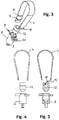
- FIG. 3 an explosion view of the device 1 has been shown.
- the body 2 and the insertable pump nipple piece 12 as well as the elastic band 15 are clearly distinguishable in this drawing.
- Fig. 4 and Fig. 5 show an explosion view of Fig. 1 and Fig. 2 , respectively.
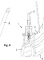
- FIG. 6 shows a perspective view of the device 1 in operation.
- a valve of a bicycle tire 16 is inserted in the recess 13 of the pump nipple 12.
- a hose 17 of a pump (not shown) is connected to the connector 3 of the device 1, such that when operating the pump air will be moved through the fluid flow path 11, inflating the tire 16.
- the elastic band 4 is guided over the tire 16 and rim 18 and is coupled to the device 1.
- the invention also relates to all combinations of features described here independently of each other.
Landscapes
- Engineering & Computer Science (AREA)
- Mechanical Engineering (AREA)
- General Engineering & Computer Science (AREA)
- Compressors, Vaccum Pumps And Other Relevant Systems (AREA)
- Check Valves (AREA)
Abstract
Description
- The present invention relates to a device for coupling a tire pump to a valve of a tire according to the preamble of
claim 1. The invention also relates to a set comprising the device and a plurality a pump nipples according toclaim 12 as well as to a method for increasing the pressure in a tire according toclaim 13. - It is known in the art to increase the pressure in a tire by coupling a pump nipple to a valve of said tire, the pump nipple being connected to a pump, and operating said pump. Known devices comprise a rubber compression mechanism operated by a lever that seals the pump nipple around the valve, like with Presta-type valves, or that require a strong hand to push the pump nipple airtight against the valve, like with Schrader-type valves. Alternatively, when increasing the pressure in a tire with a so-called Dunlop- or Blitz-type valve, a specially designed clamp is required to keep the pump nipple coupled to the valve.
- Such known devices each have the disadvantage that a cumbersome coupling action is required to couple the pump nipple to the valve.
- Also, in case of the rubber compression mechanism required for Presta-type valves and the clamp for Dunlop- and Blitz-type valves, the pump or nipple device itself requires complicated equipment to enable a user to efficiently increase the pressure in the tire.
- The term "device for increasing the pressure in a tire" relates to the construction part that is placed in between the valve and the pump. It may be a separate constructional part that can be stored independently from the pump but it may also form part of the pump, especially in the case of a bicycle pump that is taken on a bike ride.
- The invention aims at providing an improved device for increasing the pressure in a tire of the kind mentioned in the preamble.
- The invention further aims at providing a method for increasing the pressure in a tire, the method applying the device according to the present invention.
- So as to obtain at least one of the above mentioned aims, the invention provides a device as mentioned in
claim 1. This device has the advantage that it can be used for every type of valve without any additional accessory. As a matter of fact, it can also be used with valves that are provided with reducing valves, as is the case with some valves of moped tires. No effort is required to keep the device, more in particular the pump nipple, in airtight connection with the valve. - It has also shown that the device according to the present invention can be manufactured easily and cheaply. Also, the weight of the device according to the present invention is substantially less than the weight of known mechanisms to couple a nipple to a valve. Such synergistic effect is a surprising and advantageous effect.
- The invention therefore relates to a device for coupling a tire pump to a valve of a tire and for providing a fluid flow path from said pump to said valve, comprising a pump nipple for covering said valve, the device being characterized in that the device comprises an elastic band coupled to a body of said device, said band being embodied for positioning around said tire under elastic force. Since the elastic band provides the force required to keep the nipple placed on the valve, no manual action by the user is required.
- For example, the device may be coupled to a hose of a pump. However, the invention is not limited thereto, since a pump may be connected directly to the valve, as is common in bike pumps. The device therefore may be connected directly to a pump.
- According to a preferred embodiment, the pump nipple comprises a recess with an access opening for receiving said valve. Hence, the valve is received within the recess such that the device at least partially surrounds the valve. Such provides a more secure coupling with less risk of the nipple coming off the valve.
- In a further preferred embodiment said recess has an inner wall tapering towards a position away from said access opening. Preferably, the diameter of the recess at the access opening thereof has a diameter to be able to receive a largest diameter valve, whereas the smallest diameter of the recess is sufficient large to abut a smallest diameter valve. In such case, the pump nipple can fittingly receive all diameter valves to increase the pressure in a respective tire without air leakage.
- A more secure and airtight coupling of the pump nipple to the valve is obtained when an inner wall of said recess is covered with a compressible material. The valve's material will compress said material when the pump nipple is pulled against the valve due to the elastic band's force, such that an airtight seal is obtained.
- A simple embodiment is obtained when said pump nipple is embodied as a single piece with said body, i.e. as a unitary body. Only a single manufacturing step is required, without the need to assemble multiple parts, which yields a cheap device.
- When the device is envisaged for use with multiple types of valves, the pump nipple may preferably be embodied as an insertable piece in a recess provided in said body. A cyclist riding a bike with racing tires then only needs to take the body with a pump nipple that exactly fits a Presta valve, whereas at home he may use the device using a pump nipple with a larger access opening so as to inflate tires with other valves like a Schrader- or Dunlop-type valve. In such cases, a pump nipple may be used that exactly fits a single valve-type only as is preferred by some people, for example because of a reduced size of such exactly fitting pump nipple.
- When using a device with a replaceable pump nipple, it is preferred that at least one of abutting walls of said body and said insertable piece is provided with a compressible material. Not a complete abutting surface needs to be provided with a compressible material, part of such surface can be provided therewith, ensuring that an airtight seal is obtained.
- As mentioned above, the device is embodied for providing a fluid connection between the pump and the valve of the tire, more in particular between the pump and the tire so as to be able to inflate said tire by means of said pump. The device thereto for example comprises a connector for coupling a tire pump to said device, the connector being in fluid connection with the pump nipple. The connector may be embodied for coupling a hose thereto of for directly coupling same to the housing of a pump.
- A very convenient coupling of the device is obtained when the elastic band is coupled to opposite sides of the device. When the elastic band is guided along the tire, one end of the elastic band may be positioned at a left side of the tire whereas the other end of the elastic band may be positioned at a right side of the tire. The device thus is coupled stably to the elastic band when coupling positions for the band are positioned at opposite sides of the device.
- So as to be able to easily remove the device from the valve, the elastic band is preferably removably coupled at at least one position of said device.
- The device according to the present invention can be used for inflating many different sizes of tires. Since different sizes of tires usually have different heights, it is preferred that the elastic band is provided with at least two coupling positions for removably coupling same at at least a first or a second position to the device.
- According to a further embodiment, the present invention relates to a set comprising a device according to the invention wherein the pump nipple is embodied as an insertable optionally in combination with any of claims 2-5, comprising said device and at least two pump nipples, wherein a diameter of an access opening of a first pump nipple is larger than the diameter of the access opening of another pump nipple, preferably at least three pump nipples each pump nipple having a differently sized diameter of access opening.
- According to a still further embodiment, the invention relates to a method for increasing the pressure in a tire, comprising the steps of positioning a device according to the present invention on a valve of said tire, placing the elastic band around the tire and coupling same to the device, for example at opposite sides of the device, and operating said pump. By this method, an easy way of inflating a tire is obtained.
- In the method, it is preferred to perform the step of applying a pump nipple with an access opening that fits the tire's valve. This ensures an airtight seal of the pump nipple on the valve, allowing one to easily and fast inflating the tie.
- As mentioned before with reference to the device according to the invention, it is preferred that the elastic band is removably coupled at at least one position of said device, for example at least one side of said device.
- Hereafter, the invention will be further described by means of a drawing. The drawing shows in:
-
Fig. 1 a side view of the device according to the invention, -
Fig. 2 a sectional view of the device according to the invention, -
Fig. 3 a perspective explosion view of the device according to the invention, -
Fig. 4 an explosion view from the side of the device according to the invention, -
Fig. 5 a sectional explosion view of the device according to the invention, and -
Fig. 6 a perspective view of the device according to the invention, a tire and a pump. - The same and similar parts and features have been denoted by the same reference numerals in the figures. However, for ease of understanding the figures, not all parts that are required for a practical embodiment have been shown in the figures.
-
Fig. 1 shows a side view of thedevice 1 according to the invention. Thedevice 1 comprises abody 2 with aconnector 3 for a hose of a pump (not shown in this figure). The hose may be clampingly fitted as such or a hose clamp may be applied. An elastic band 4 is coupled to thebody 2. A first end 5 of the band 4 is coupled to a first side 6 of thebody 2 whereas the band 4 is coupled to thebody 2 at aremote position 7 to an opposite side 8 of thebody 2. Hence, the elastic band 4 forms a loop. - Coupling of the band 4 to the
body 2 is easily obtained by means ofnotches 9, for example at thebody 2, for mutual cooperation withopenings 10, for example in the elastic band 4. As shown also inFig. 1 and Fig. 2 , the band 4 may comprise anotch 19 for positioning behind ashoulder 20 of a coupling member at thebody 2. -
Fig. 2 shows a sectional view of the device shown inFig. 1 . The parts as referred to in the description ofFig. 1 can be easily recognized. In addition,Fig. 2 shows the fluid flow path 11 (indicated by a dashed line) gas will flow when operating the pump referred to above for inflating a tire (not shown). The flow path extends from theconnector 3 to anopening 13 in thebody 2 for receiving a valve of a tire. - The band 4 comprises a plurality of
openings 10 so as to be able to increase or decrease the length of the loop. -
Fig. 2 shows aninsertable piece 12 in thebody 2. This insertable (and removable)piece 12 comprises apump nipple 12 for receiving a valve (not shown) of the tire to be inflated. The tire's valve is to be received in therecess 13 through access opening 14, as shown inFig. 5 . Since the inside wall 15 (also as shown inFig. 5 ) ofpump nipple 12 is tapering towards the inside, the depth to which the valve is inserted depends on the diameter of said valve and said inside wall 15. Valves of many different sizes can be used with thepresent pump nipple 12 due to the tapering wall 15. - In
Fig. 3 an explosion view of thedevice 1 has been shown. Thebody 2 and the insertablepump nipple piece 12 as well as the elastic band 15 are clearly distinguishable in this drawing. -
Fig. 4 and Fig. 5 show an explosion view ofFig. 1 and Fig. 2 , respectively. - Finally,
Fig. 6 shows a perspective view of thedevice 1 in operation. A valve of abicycle tire 16 is inserted in therecess 13 of thepump nipple 12. Ahose 17 of a pump (not shown) is connected to theconnector 3 of thedevice 1, such that when operating the pump air will be moved through the fluid flow path 11, inflating thetire 16. The elastic band 4 is guided over thetire 16 andrim 18 and is coupled to thedevice 1. - The invention is not limited to the embodiments as mentioned above and as shown in the drawings. The invention is limited by the claims only.
- The invention also relates to all combinations of features described here independently of each other.
Claims (15)
- A device for coupling a tire pump to a valve of a tire and for providing a fluid flow path from said pump to said valve, comprising a pump nipple for covering said valve, characterized in that the device comprises an elastic band coupled to a body of said device, said band being embodied for positioning around said tire under elastic force.
- A device according to claim 1, wherein said pump nipple comprises a recess with an access opening for receiving said valve.
- A device according to claim 2, wherein said recess has an inner wall tapering towards a position away from said access opening.
- A device according to claim 2, wherein an inner wall of said recess is covered with a compressible material.
- A device according to claim 1, wherein said pump nipple is embodied as a single piece with said body.
- A device according to claim 1, wherein said pump nipple is embodied as an insertable piece in a recess provided in said body.
- A device according to any of claim 6, wherein at least one of abutting walls of said body and said insertable piece is provided with a compressible material.
- A device according to claim 1, wherein the device comprises a connector for coupling a tire pump to said device, the connector being in fluid connection with the pump nipple.
- A device according to claim 1, wherein said elastic band is coupled at opposite sides of said device.
- A device according to claim 1, wherein the elastic band is removably coupled at at least one position of said device.
- A device according to claim 10, wherein the elastic band is provided with at least two coupling positions for removably coupling same at at least a first or a second position to the device.
- A set comprising a device according to any of claims 6-11, optionally in combination with any of claims 2-5, comprising said device and at least two pump nipples, wherein a diameter of an access opening of a first pump nipple is larger than the diameter of the access opening of another pump nipple, preferably at least three pump nipples, each pump nipple having a differently sized diameter of access opening.
- A method for increasing the pressure in a tire, comprising the steps of positioning a device according to any of claims 1-11 on a valve of said tire, placing the elastic band around the tire and coupling same to the device and operating said pump, preferably coupling the elastic band at opposite sides of the device.
- A method according to claim 13 in combination with claim 6, comprising the steps of applying a pump nipple with an access opening that fits the tire's valve.
- A method according to claim 13, wherein the elastic band is removably coupled at at least one position of said device.
Priority Applications (13)
| Application Number | Priority Date | Filing Date | Title |
|---|---|---|---|
| PL17203811T PL3489045T3 (en) | 2017-11-27 | 2017-11-27 | A device for coupling a tire pump to a valve of a tire, a set of the device and pump nipples and a method for increasing the pressure in a tire |
| DK17203811.9T DK3489045T3 (en) | 2017-11-27 | 2017-11-27 | A DEVICE FOR COUPLING A TIRE PUMP TO A VALVE OF A TIRE, A SET OF THE DEVICE AND PUMP NIPPLES AND A PROCEDURE TO INCREASE THE PRESSURE IN A TIRE |
| SM20200650T SMT202000650T1 (en) | 2017-11-27 | 2017-11-27 | A device for coupling a tire pump to a valve of a tire, a set of the device and pump nipples and a method for increasing the pressure in a tire |
| PT172038119T PT3489045T (en) | 2017-11-27 | 2017-11-27 | A device for coupling a tire pump to a valve of a tire, a set of the device and pump nipples and a method for increasing the pressure in a tire |
| SI201730501T SI3489045T1 (en) | 2017-11-27 | 2017-11-27 | A device for coupling a tire pump to a valve of a tire, a set of the device and pump nipples and a method for increasing the pressure in a tire |
| LTEP17203811.9T LT3489045T (en) | 2017-11-27 | 2017-11-27 | A device for coupling a tire pump to a valve of a tire, a set of the device and pump nipples and a method for increasing the pressure in a tire |
| ES17203811T ES2836249T3 (en) | 2017-11-27 | 2017-11-27 | A device for coupling a tire pump to a valve of a tire, an assembly of the device and pump nozzles, and a method for increasing the pressure of a tire |
| HUE17203811A HUE052607T2 (en) | 2017-11-27 | 2017-11-27 | A device for coupling a tire pump to a valve of a tire, a set of the device and pump nipples and a method for increasing the pressure in a tire |
| EP17203811.9A EP3489045B1 (en) | 2017-11-27 | 2017-11-27 | A device for coupling a tire pump to a valve of a tire, a set of the device and pump nipples and a method for increasing the pressure in a tire |
| RS20201442A RS61180B1 (en) | 2017-11-27 | 2017-11-27 | A device for coupling a tire pump to a valve of a tire, a set of the device and pump nipples and a method for increasing the pressure in a tire |
| US16/199,888 US11167605B2 (en) | 2017-11-27 | 2018-11-26 | Device for coupling a tire pump to a valve of a tire, a set of the device and pump nipples and a method for increasing the pressure in a tire |
| CY20201101092T CY1123594T1 (en) | 2017-11-27 | 2020-11-18 | DEVICE FOR CONNECTING A TIRE PUMP TO THE VALVE OF A TIRE, THE DEVICE ASSEMBLY AND PUMP NIPPLE AND A METHOD FOR INCREASING THE PRESSURE IN A TIRE |
| HRP20201913TT HRP20201913T1 (en) | 2017-11-27 | 2020-12-01 | A device for coupling a tire pump to a valve of a tire, a set of the device and pump nipples and a method for increasing the pressure in a tire |
Applications Claiming Priority (1)
| Application Number | Priority Date | Filing Date | Title |
|---|---|---|---|
| EP17203811.9A EP3489045B1 (en) | 2017-11-27 | 2017-11-27 | A device for coupling a tire pump to a valve of a tire, a set of the device and pump nipples and a method for increasing the pressure in a tire |
Publications (2)
| Publication Number | Publication Date |
|---|---|
| EP3489045A1 true EP3489045A1 (en) | 2019-05-29 |
| EP3489045B1 EP3489045B1 (en) | 2020-09-16 |
Family
ID=60473409
Family Applications (1)
| Application Number | Title | Priority Date | Filing Date |
|---|---|---|---|
| EP17203811.9A Active EP3489045B1 (en) | 2017-11-27 | 2017-11-27 | A device for coupling a tire pump to a valve of a tire, a set of the device and pump nipples and a method for increasing the pressure in a tire |
Country Status (13)
| Country | Link |
|---|---|
| US (1) | US11167605B2 (en) |
| EP (1) | EP3489045B1 (en) |
| CY (1) | CY1123594T1 (en) |
| DK (1) | DK3489045T3 (en) |
| ES (1) | ES2836249T3 (en) |
| HR (1) | HRP20201913T1 (en) |
| HU (1) | HUE052607T2 (en) |
| LT (1) | LT3489045T (en) |
| PL (1) | PL3489045T3 (en) |
| PT (1) | PT3489045T (en) |
| RS (1) | RS61180B1 (en) |
| SI (1) | SI3489045T1 (en) |
| SM (1) | SMT202000650T1 (en) |
Citations (6)
| Publication number | Priority date | Publication date | Assignee | Title |
|---|---|---|---|---|
| BE464836A (en) * | ||||
| DE188558C (en) * | ||||
| US688698A (en) * | 1901-04-08 | 1901-12-10 | Carl Brieger | Valve and inflater connection for pneumatic tires, &c. |
| FR530163A (en) * | 1921-01-25 | 1921-12-17 | Seal plug for pneumatic pumps | |
| FR537939A (en) * | 1921-07-05 | 1922-06-01 | Fitting for pumps of bicycles, automobiles, etc. | |
| WO1994018452A2 (en) * | 1993-02-12 | 1994-08-18 | Spanninga Metaal B.V. | A bicycle pump |
Family Cites Families (4)
| Publication number | Priority date | Publication date | Assignee | Title |
|---|---|---|---|---|
| US2710038A (en) * | 1953-01-23 | 1955-06-07 | Sr Charles T Holzmueller | Anti-skid device |
| USD305097S (en) * | 1987-01-05 | 1989-12-19 | Converse Rhea P | Cinch for holding a pneumatic pump head onto a tire valve |
| US6978796B2 (en) * | 2002-09-25 | 2005-12-27 | Morris Ostrowiecki | Universal air valve connector |
| DE102008053562A1 (en) * | 2008-07-23 | 2010-01-28 | Doukas Ag | Device for filling pneumatic tires with a tire sealing fluid |
-
2017
- 2017-11-27 ES ES17203811T patent/ES2836249T3/en active Active
- 2017-11-27 RS RS20201442A patent/RS61180B1/en unknown
- 2017-11-27 PL PL17203811T patent/PL3489045T3/en unknown
- 2017-11-27 EP EP17203811.9A patent/EP3489045B1/en active Active
- 2017-11-27 PT PT172038119T patent/PT3489045T/en unknown
- 2017-11-27 HU HUE17203811A patent/HUE052607T2/en unknown
- 2017-11-27 SM SM20200650T patent/SMT202000650T1/en unknown
- 2017-11-27 DK DK17203811.9T patent/DK3489045T3/en active
- 2017-11-27 LT LTEP17203811.9T patent/LT3489045T/en unknown
- 2017-11-27 SI SI201730501T patent/SI3489045T1/en unknown
-
2018
- 2018-11-26 US US16/199,888 patent/US11167605B2/en not_active Expired - Fee Related
-
2020
- 2020-11-18 CY CY20201101092T patent/CY1123594T1/en unknown
- 2020-12-01 HR HRP20201913TT patent/HRP20201913T1/en unknown
Patent Citations (6)
| Publication number | Priority date | Publication date | Assignee | Title |
|---|---|---|---|---|
| BE464836A (en) * | ||||
| DE188558C (en) * | ||||
| US688698A (en) * | 1901-04-08 | 1901-12-10 | Carl Brieger | Valve and inflater connection for pneumatic tires, &c. |
| FR530163A (en) * | 1921-01-25 | 1921-12-17 | Seal plug for pneumatic pumps | |
| FR537939A (en) * | 1921-07-05 | 1922-06-01 | Fitting for pumps of bicycles, automobiles, etc. | |
| WO1994018452A2 (en) * | 1993-02-12 | 1994-08-18 | Spanninga Metaal B.V. | A bicycle pump |
Also Published As
| Publication number | Publication date |
|---|---|
| RS61180B1 (en) | 2021-01-29 |
| SMT202000650T1 (en) | 2021-01-05 |
| PT3489045T (en) | 2020-11-30 |
| HUE052607T2 (en) | 2021-05-28 |
| US20190160897A1 (en) | 2019-05-30 |
| LT3489045T (en) | 2021-02-25 |
| HRP20201913T1 (en) | 2021-01-22 |
| SI3489045T1 (en) | 2021-02-26 |
| DK3489045T3 (en) | 2020-12-07 |
| PL3489045T3 (en) | 2021-07-12 |
| ES2836249T3 (en) | 2021-06-24 |
| US11167605B2 (en) | 2021-11-09 |
| EP3489045B1 (en) | 2020-09-16 |
| CY1123594T1 (en) | 2022-03-24 |
Similar Documents
| Publication | Publication Date | Title |
|---|---|---|
| US8360090B2 (en) | Schrader valve/Presta valve dual-purpose valve cap | |
| US8402987B2 (en) | Schrader valve/Presta valve dual-mode valve cap | |
| US9249914B2 (en) | Connector structure for a Schrader (American) valve/Presta (French) valve | |
| US6260572B1 (en) | Valve-coupling device for an inflation device | |
| US9511636B2 (en) | Joint structure for an air nozzle | |
| US7681489B2 (en) | Extendable pipe unit for frame floor pump | |
| US8245722B2 (en) | Inflation nozzle capable of connecting with two types of tire valves | |
| US8839809B1 (en) | Attachment for different air valves | |
| US8402989B2 (en) | Telescopic pump nozzle adapted for engaging with different tire valves for tire inflation | |
| US8651458B2 (en) | Hand-operating vacuum pulling device | |
| CN107874651B (en) | Vacuum cup | |
| US20040086404A1 (en) | Pump capable of releasing excessive air | |
| US20100154897A1 (en) | Valve device for an inflatable object | |
| US10247319B1 (en) | Pump head | |
| US20140190576A1 (en) | Horizontally-triggerable inflation connector | |
| EP2497657B1 (en) | Tire pressure relase apparatus and method | |
| US20090229677A1 (en) | Pump connector device for different valves | |
| US20170009922A1 (en) | Quick Connector Structure for a Pneumatic Valve | |
| US20160237995A1 (en) | Push On and Pull Off Schrader and Presta Valve Air Filler Pump Head | |
| US11167605B2 (en) | Device for coupling a tire pump to a valve of a tire, a set of the device and pump nipples and a method for increasing the pressure in a tire | |
| EP2390502A1 (en) | Inflation nozzle capable of connecting with two types of tire valves | |
| EP2770207B1 (en) | Automatic-switch nozzle head having two valve mouths and single-mouth nozzle head | |
| EP1311780B1 (en) | Bleed valve assembly | |
| US20110068132A1 (en) | Tire inflation device | |
| CN110005943B (en) | Inflating device with screw inflating head |
Legal Events
| Date | Code | Title | Description |
|---|---|---|---|
| PUAI | Public reference made under article 153(3) epc to a published international application that has entered the european phase |
Free format text: ORIGINAL CODE: 0009012 |
|
| STAA | Information on the status of an ep patent application or granted ep patent |
Free format text: STATUS: THE APPLICATION HAS BEEN PUBLISHED |
|
| AK | Designated contracting states |
Kind code of ref document: A1 Designated state(s): AL AT BE BG CH CY CZ DE DK EE ES FI FR GB GR HR HU IE IS IT LI LT LU LV MC MK MT NL NO PL PT RO RS SE SI SK SM TR |
|
| AX | Request for extension of the european patent |
Extension state: BA ME |
|
| STAA | Information on the status of an ep patent application or granted ep patent |
Free format text: STATUS: REQUEST FOR EXAMINATION WAS MADE |
|
| 17P | Request for examination filed |
Effective date: 20191128 |
|
| RBV | Designated contracting states (corrected) |
Designated state(s): AL AT BE BG CH CY CZ DE DK EE ES FI FR GB GR HR HU IE IS IT LI LT LU LV MC MK MT NL NO PL PT RO RS SE SI SK SM TR |
|
| GRAP | Despatch of communication of intention to grant a patent |
Free format text: ORIGINAL CODE: EPIDOSNIGR1 |
|
| RIC1 | Information provided on ipc code assigned before grant |
Ipc: F04B 33/00 20060101ALI20200302BHEP Ipc: B60C 29/06 20060101AFI20200302BHEP Ipc: F04B 39/10 20060101ALI20200302BHEP |
|
| STAA | Information on the status of an ep patent application or granted ep patent |
Free format text: STATUS: GRANT OF PATENT IS INTENDED |
|
| INTG | Intention to grant announced |
Effective date: 20200409 |
|
| GRAS | Grant fee paid |
Free format text: ORIGINAL CODE: EPIDOSNIGR3 |
|
| GRAA | (expected) grant |
Free format text: ORIGINAL CODE: 0009210 |
|
| STAA | Information on the status of an ep patent application or granted ep patent |
Free format text: STATUS: THE PATENT HAS BEEN GRANTED |
|
| AK | Designated contracting states |
Kind code of ref document: B1 Designated state(s): AL AT BE BG CH CY CZ DE DK EE ES FI FR GB GR HR HU IE IS IT LI LT LU LV MC MK MT NL NO PL PT RO RS SE SI SK SM TR |
|
| REG | Reference to a national code |
Ref country code: GB Ref legal event code: FG4D |
|
| REG | Reference to a national code |
Ref country code: CH Ref legal event code: EP |
|
| REG | Reference to a national code |
Ref country code: DE Ref legal event code: R096 Ref document number: 602017023669 Country of ref document: DE |
|
| REG | Reference to a national code |
Ref country code: IE Ref legal event code: FG4D |
|
| REG | Reference to a national code |
Ref country code: AT Ref legal event code: REF Ref document number: 1313839 Country of ref document: AT Kind code of ref document: T Effective date: 20201015 |
|
| REG | Reference to a national code |
Ref country code: PT Ref legal event code: SC4A Ref document number: 3489045 Country of ref document: PT Date of ref document: 20201130 Kind code of ref document: T Free format text: AVAILABILITY OF NATIONAL TRANSLATION Effective date: 20201124 |
|
| REG | Reference to a national code |
Ref country code: HR Ref legal event code: TUEP Ref document number: P20201913T Country of ref document: HR |
|
| REG | Reference to a national code |
Ref country code: FI Ref legal event code: FGE |
|
| REG | Reference to a national code |
Ref country code: DK Ref legal event code: T3 Effective date: 20201202 |
|
| REG | Reference to a national code |
Ref country code: SE Ref legal event code: TRGR |
|
| RAP2 | Party data changed (patent owner data changed or rights of a patent transferred) |
Owner name: N VERHOEVEN HOLDING B.V. |
|
| REG | Reference to a national code |
Ref country code: CH Ref legal event code: NV Representative=s name: VALIPAT S.A. C/O BOVARD SA NEUCHATEL, CH |
|
| REG | Reference to a national code |
Ref country code: NL Ref legal event code: FP |
|
| REG | Reference to a national code |
Ref country code: HR Ref legal event code: ODRP Ref document number: P20201913T Country of ref document: HR Payment date: 20210101 Year of fee payment: 4 |
|
| REG | Reference to a national code |
Ref country code: EE Ref legal event code: FG4A Ref document number: E020049 Country of ref document: EE Effective date: 20201123 |
|
| REG | Reference to a national code |
Ref country code: HR Ref legal event code: T1PR Ref document number: P20201913 Country of ref document: HR |
|
| REG | Reference to a national code |
Ref country code: NO Ref legal event code: T2 Effective date: 20200916 |
|
| REG | Reference to a national code |
Ref country code: DE Ref legal event code: R081 Ref document number: 602017023669 Country of ref document: DE Owner name: N VERHOEVEN HOLDING B.V., NL Free format text: FORMER OWNER: N VERHOEVEN HOLDING B.V., CULEMBORG, NL |
|
| REG | Reference to a national code |
Ref country code: SK Ref legal event code: T3 Ref document number: E 36217 Country of ref document: SK |
|
| REG | Reference to a national code |
Ref country code: EE Ref legal event code: HC1A Ref document number: E020049 Country of ref document: EE |
|
| REG | Reference to a national code |
Ref country code: HU Ref legal event code: AG4A Ref document number: E052607 Country of ref document: HU |
|
| REG | Reference to a national code |
Ref country code: DE Ref legal event code: R097 Ref document number: 602017023669 Country of ref document: DE |
|
| REG | Reference to a national code |
Ref country code: ES Ref legal event code: FG2A Ref document number: 2836249 Country of ref document: ES Kind code of ref document: T3 Effective date: 20210624 |
|
| PLBE | No opposition filed within time limit |
Free format text: ORIGINAL CODE: 0009261 |
|
| STAA | Information on the status of an ep patent application or granted ep patent |
Free format text: STATUS: NO OPPOSITION FILED WITHIN TIME LIMIT |
|
| 26N | No opposition filed |
Effective date: 20210617 |
|
| REG | Reference to a national code |
Ref country code: HR Ref legal event code: ODRP Ref document number: P20201913 Country of ref document: HR Payment date: 20211125 Year of fee payment: 5 |
|
| PGFP | Annual fee paid to national office [announced via postgrant information from national office to epo] |
Ref country code: LU Payment date: 20211125 Year of fee payment: 5 |
|
| PGFP | Annual fee paid to national office [announced via postgrant information from national office to epo] |
Ref country code: FR Payment date: 20211122 Year of fee payment: 5 Ref country code: SK Payment date: 20211129 Year of fee payment: 5 Ref country code: RS Payment date: 20211123 Year of fee payment: 5 Ref country code: PT Payment date: 20211123 Year of fee payment: 5 Ref country code: SM Payment date: 20211129 Year of fee payment: 5 Ref country code: SE Payment date: 20211130 Year of fee payment: 5 Ref country code: RO Payment date: 20211124 Year of fee payment: 5 Ref country code: TR Payment date: 20211124 Year of fee payment: 5 Ref country code: NO Payment date: 20211125 Year of fee payment: 5 Ref country code: ES Payment date: 20211207 Year of fee payment: 5 Ref country code: EE Payment date: 20211130 Year of fee payment: 5 Ref country code: DE Payment date: 20211130 Year of fee payment: 5 Ref country code: DK Payment date: 20211124 Year of fee payment: 5 Ref country code: BG Payment date: 20211129 Year of fee payment: 5 Ref country code: CZ Payment date: 20211125 Year of fee payment: 5 Ref country code: GB Payment date: 20211125 Year of fee payment: 5 Ref country code: IE Payment date: 20211125 Year of fee payment: 5 Ref country code: NL Payment date: 20211115 Year of fee payment: 5 Ref country code: MC Payment date: 20211126 Year of fee payment: 5 Ref country code: LT Payment date: 20211122 Year of fee payment: 5 Ref country code: HR Payment date: 20211125 Year of fee payment: 5 Ref country code: FI Payment date: 20211125 Year of fee payment: 5 |
|
| PGFP | Annual fee paid to national office [announced via postgrant information from national office to epo] |
Ref country code: SI Payment date: 20211123 Year of fee payment: 5 Ref country code: LV Payment date: 20211129 Year of fee payment: 5 Ref country code: IT Payment date: 20211126 Year of fee payment: 5 Ref country code: IS Payment date: 20211130 Year of fee payment: 5 Ref country code: HU Payment date: 20211122 Year of fee payment: 5 Ref country code: GR Payment date: 20211129 Year of fee payment: 5 Ref country code: CH Payment date: 20211122 Year of fee payment: 5 Ref country code: BE Payment date: 20211125 Year of fee payment: 5 |
|
| PGFP | Annual fee paid to national office [announced via postgrant information from national office to epo] |
Ref country code: PL Payment date: 20211123 Year of fee payment: 5 Ref country code: MT Payment date: 20211130 Year of fee payment: 5 Ref country code: MK Payment date: 20211125 Year of fee payment: 5 |
|
| PGFP | Annual fee paid to national office [announced via postgrant information from national office to epo] |
Ref country code: CY Payment date: 20211122 Year of fee payment: 5 |
|
| PGFP | Annual fee paid to national office [announced via postgrant information from national office to epo] |
Ref country code: AL Payment date: 20211201 Year of fee payment: 5 |
|
| REG | Reference to a national code |
Ref country code: AT Ref legal event code: UEP Ref document number: 1313839 Country of ref document: AT Kind code of ref document: T Effective date: 20200916 |
|
| REG | Reference to a national code |
Ref country code: DE Ref legal event code: R119 Ref document number: 602017023669 Country of ref document: DE |
|
| REG | Reference to a national code |
Ref country code: HR Ref legal event code: PBON Ref document number: P20201913 Country of ref document: HR Effective date: 20221127 |
|
| REG | Reference to a national code |
Ref country code: EE Ref legal event code: MM4A Ref document number: E020049 Country of ref document: EE Effective date: 20221130 |
|
| REG | Reference to a national code |
Ref country code: DK Ref legal event code: EBP Effective date: 20221130 |
|
| REG | Reference to a national code |
Ref country code: NO Ref legal event code: MMEP Ref country code: LT Ref legal event code: MM4D Effective date: 20221127 |
|
| PG25 | Lapsed in a contracting state [announced via postgrant information from national office to epo] |
Ref country code: MC Free format text: LAPSE BECAUSE OF NON-PAYMENT OF DUE FEES Effective date: 20221130 |
|
| REG | Reference to a national code |
Ref country code: CH Ref legal event code: PL |
|
| REG | Reference to a national code |
Ref country code: SE Ref legal event code: EUG |
|
| REG | Reference to a national code |
Ref country code: NL Ref legal event code: MM Effective date: 20221201 |
|
| REG | Reference to a national code |
Ref country code: SK Ref legal event code: MM4A Ref document number: E 36217 Country of ref document: SK Effective date: 20221127 |
|
| GBPC | Gb: european patent ceased through non-payment of renewal fee |
Effective date: 20221127 |
|
| REG | Reference to a national code |
Ref country code: BE Ref legal event code: MM Effective date: 20221130 |
|
| PG25 | Lapsed in a contracting state [announced via postgrant information from national office to epo] |
Ref country code: SM Free format text: LAPSE BECAUSE OF NON-PAYMENT OF DUE FEES Effective date: 20230620 Ref country code: RS Free format text: LAPSE BECAUSE OF NON-PAYMENT OF DUE FEES Effective date: 20221127 Ref country code: RO Free format text: LAPSE BECAUSE OF NON-PAYMENT OF DUE FEES Effective date: 20221127 Ref country code: PT Free format text: LAPSE BECAUSE OF NON-PAYMENT OF DUE FEES Effective date: 20230529 Ref country code: NO Free format text: LAPSE BECAUSE OF NON-PAYMENT OF DUE FEES Effective date: 20221130 Ref country code: LV Free format text: LAPSE BECAUSE OF NON-PAYMENT OF DUE FEES Effective date: 20221127 Ref country code: LT Free format text: LAPSE BECAUSE OF NON-PAYMENT OF DUE FEES Effective date: 20221127 Ref country code: LI Free format text: LAPSE BECAUSE OF NON-PAYMENT OF DUE FEES Effective date: 20221130 Ref country code: HU Free format text: LAPSE BECAUSE OF NON-PAYMENT OF DUE FEES Effective date: 20221128 Ref country code: EE Free format text: LAPSE BECAUSE OF NON-PAYMENT OF DUE FEES Effective date: 20221130 Ref country code: CZ Free format text: LAPSE BECAUSE OF NON-PAYMENT OF DUE FEES Effective date: 20221127 Ref country code: CY Free format text: LAPSE BECAUSE OF NON-PAYMENT OF DUE FEES Effective date: 20221127 Ref country code: CH Free format text: LAPSE BECAUSE OF NON-PAYMENT OF DUE FEES Effective date: 20221130 |
|
| PG25 | Lapsed in a contracting state [announced via postgrant information from national office to epo] |
Ref country code: SK Free format text: LAPSE BECAUSE OF NON-PAYMENT OF DUE FEES Effective date: 20221127 Ref country code: SI Free format text: LAPSE BECAUSE OF NON-PAYMENT OF DUE FEES Effective date: 20221128 Ref country code: SE Free format text: LAPSE BECAUSE OF NON-PAYMENT OF DUE FEES Effective date: 20221128 Ref country code: LU Free format text: LAPSE BECAUSE OF NON-PAYMENT OF DUE FEES Effective date: 20221127 Ref country code: GR Free format text: LAPSE BECAUSE OF NON-PAYMENT OF DUE FEES Effective date: 20230609 Ref country code: NL Free format text: LAPSE BECAUSE OF NON-PAYMENT OF DUE FEES Effective date: 20221201 |
|
| REG | Reference to a national code |
Ref country code: SI Ref legal event code: KO00 Effective date: 20230712 |
|
| PG25 | Lapsed in a contracting state [announced via postgrant information from national office to epo] |
Ref country code: IT Free format text: LAPSE BECAUSE OF NON-PAYMENT OF DUE FEES Effective date: 20221127 Ref country code: IE Free format text: LAPSE BECAUSE OF NON-PAYMENT OF DUE FEES Effective date: 20221127 Ref country code: GB Free format text: LAPSE BECAUSE OF NON-PAYMENT OF DUE FEES Effective date: 20221127 Ref country code: DK Free format text: LAPSE BECAUSE OF NON-PAYMENT OF DUE FEES Effective date: 20221130 Ref country code: DE Free format text: LAPSE BECAUSE OF NON-PAYMENT OF DUE FEES Effective date: 20230601 |
|
| PG25 | Lapsed in a contracting state [announced via postgrant information from national office to epo] |
Ref country code: HR Free format text: LAPSE BECAUSE OF NON-PAYMENT OF DUE FEES Effective date: 20221127 Ref country code: FR Free format text: LAPSE BECAUSE OF NON-PAYMENT OF DUE FEES Effective date: 20221130 Ref country code: BE Free format text: LAPSE BECAUSE OF NON-PAYMENT OF DUE FEES Effective date: 20221130 |
|
| REG | Reference to a national code |
Ref country code: ES Ref legal event code: FD2A Effective date: 20240102 |
|
| REG | Reference to a national code |
Ref country code: AT Ref legal event code: MM01 Ref document number: 1313839 Country of ref document: AT Kind code of ref document: T Effective date: 20221127 |
|
| PG25 | Lapsed in a contracting state [announced via postgrant information from national office to epo] |
Ref country code: ES Free format text: LAPSE BECAUSE OF NON-PAYMENT OF DUE FEES Effective date: 20221128 |
|
| PG25 | Lapsed in a contracting state [announced via postgrant information from national office to epo] |
Ref country code: ES Free format text: LAPSE BECAUSE OF NON-PAYMENT OF DUE FEES Effective date: 20221128 Ref country code: AT Free format text: LAPSE BECAUSE OF NON-PAYMENT OF DUE FEES Effective date: 20221127 |
|
| PG25 | Lapsed in a contracting state [announced via postgrant information from national office to epo] |
Ref country code: FI Free format text: LAPSE BECAUSE OF NON-PAYMENT OF DUE FEES Effective date: 20221127 |
|
| PG25 | Lapsed in a contracting state [announced via postgrant information from national office to epo] |
Ref country code: PL Free format text: LAPSE BECAUSE OF NON-PAYMENT OF DUE FEES Effective date: 20221127 |
|
| PG25 | Lapsed in a contracting state [announced via postgrant information from national office to epo] |
Ref country code: BG Free format text: LAPSE BECAUSE OF NON-PAYMENT OF DUE FEES Effective date: 20221127 |
|
| PG25 | Lapsed in a contracting state [announced via postgrant information from national office to epo] |
Ref country code: TR Free format text: LAPSE BECAUSE OF NON-PAYMENT OF DUE FEES Effective date: 20221127 Ref country code: MT Free format text: LAPSE BECAUSE OF FAILURE TO SUBMIT A TRANSLATION OF THE DESCRIPTION OR TO PAY THE FEE WITHIN THE PRESCRIBED TIME-LIMIT Effective date: 20200916 |
|
| PG25 | Lapsed in a contracting state [announced via postgrant information from national office to epo] |
Ref country code: IS Free format text: LAPSE BECAUSE OF NON-PAYMENT OF DUE FEES Effective date: 20230606 |