EP3488888B1 - Adjustable baseplate for use with irregular tracheostomas - Google Patents
Adjustable baseplate for use with irregular tracheostomas Download PDFInfo
- Publication number
- EP3488888B1 EP3488888B1 EP18185657.6A EP18185657A EP3488888B1 EP 3488888 B1 EP3488888 B1 EP 3488888B1 EP 18185657 A EP18185657 A EP 18185657A EP 3488888 B1 EP3488888 B1 EP 3488888B1
- Authority
- EP
- European Patent Office
- Prior art keywords
- base plate
- flexible membrane
- tracheostoma
- mounting portion
- plate according
- Prior art date
- Legal status (The legal status is an assumption and is not a legal conclusion. Google has not performed a legal analysis and makes no representation as to the accuracy of the status listed.)
- Active
Links
Images

Classifications
-
- A—HUMAN NECESSITIES
- A61—MEDICAL OR VETERINARY SCIENCE; HYGIENE
- A61F—FILTERS IMPLANTABLE INTO BLOOD VESSELS; PROSTHESES; DEVICES PROVIDING PATENCY TO, OR PREVENTING COLLAPSING OF, TUBULAR STRUCTURES OF THE BODY, e.g. STENTS; ORTHOPAEDIC, NURSING OR CONTRACEPTIVE DEVICES; FOMENTATION; TREATMENT OR PROTECTION OF EYES OR EARS; BANDAGES, DRESSINGS OR ABSORBENT PADS; FIRST-AID KITS
- A61F2/00—Filters implantable into blood vessels; Prostheses, i.e. artificial substitutes or replacements for parts of the body; Appliances for connecting them with the body; Devices providing patency to, or preventing collapsing of, tubular structures of the body, e.g. stents
- A61F2/02—Prostheses implantable into the body
- A61F2/20—Larynxes; Tracheae combined with larynxes or for use therewith
-
- A—HUMAN NECESSITIES
- A61—MEDICAL OR VETERINARY SCIENCE; HYGIENE
- A61F—FILTERS IMPLANTABLE INTO BLOOD VESSELS; PROSTHESES; DEVICES PROVIDING PATENCY TO, OR PREVENTING COLLAPSING OF, TUBULAR STRUCTURES OF THE BODY, e.g. STENTS; ORTHOPAEDIC, NURSING OR CONTRACEPTIVE DEVICES; FOMENTATION; TREATMENT OR PROTECTION OF EYES OR EARS; BANDAGES, DRESSINGS OR ABSORBENT PADS; FIRST-AID KITS
- A61F13/00—Bandages or dressings; Absorbent pads
- A61F13/12—Bandages or dressings; Absorbent pads specially adapted for the head or neck
- A61F13/128—Bandages or dressings; Absorbent pads specially adapted for the head or neck specially adapted for the neck
-
- A—HUMAN NECESSITIES
- A61—MEDICAL OR VETERINARY SCIENCE; HYGIENE
- A61M—DEVICES FOR INTRODUCING MEDIA INTO, OR ONTO, THE BODY; DEVICES FOR TRANSDUCING BODY MEDIA OR FOR TAKING MEDIA FROM THE BODY; DEVICES FOR PRODUCING OR ENDING SLEEP OR STUPOR
- A61M16/00—Devices for influencing the respiratory system of patients by gas treatment, e.g. ventilators; Tracheal tubes
- A61M16/04—Tracheal tubes
- A61M16/0465—Tracheostomy tubes; Devices for performing a tracheostomy; Accessories therefor, e.g. masks, filters
- A61M16/047—Masks, filters, surgical pads, devices for absorbing secretions, specially adapted therefor
-
- A—HUMAN NECESSITIES
- A61—MEDICAL OR VETERINARY SCIENCE; HYGIENE
- A61M—DEVICES FOR INTRODUCING MEDIA INTO, OR ONTO, THE BODY; DEVICES FOR TRANSDUCING BODY MEDIA OR FOR TAKING MEDIA FROM THE BODY; DEVICES FOR PRODUCING OR ENDING SLEEP OR STUPOR
- A61M16/00—Devices for influencing the respiratory system of patients by gas treatment, e.g. ventilators; Tracheal tubes
- A61M16/04—Tracheal tubes
- A61M16/0465—Tracheostomy tubes; Devices for performing a tracheostomy; Accessories therefor, e.g. masks, filters
- A61M16/0468—Tracheostomy tubes; Devices for performing a tracheostomy; Accessories therefor, e.g. masks, filters with valves at the proximal end limiting exhalation, e.g. during speaking or coughing
-
- A—HUMAN NECESSITIES
- A61—MEDICAL OR VETERINARY SCIENCE; HYGIENE
- A61M—DEVICES FOR INTRODUCING MEDIA INTO, OR ONTO, THE BODY; DEVICES FOR TRANSDUCING BODY MEDIA OR FOR TAKING MEDIA FROM THE BODY; DEVICES FOR PRODUCING OR ENDING SLEEP OR STUPOR
- A61M16/00—Devices for influencing the respiratory system of patients by gas treatment, e.g. ventilators; Tracheal tubes
- A61M16/10—Preparation of respiratory gases or vapours
- A61M16/1045—Devices for humidifying or heating the inspired gas by using recovered moisture or heat from the expired gas
-
- A—HUMAN NECESSITIES
- A61—MEDICAL OR VETERINARY SCIENCE; HYGIENE
- A61M—DEVICES FOR INTRODUCING MEDIA INTO, OR ONTO, THE BODY; DEVICES FOR TRANSDUCING BODY MEDIA OR FOR TAKING MEDIA FROM THE BODY; DEVICES FOR PRODUCING OR ENDING SLEEP OR STUPOR
- A61M2209/00—Ancillary equipment
- A61M2209/08—Supports for equipment
- A61M2209/088—Supports for equipment on the body
Definitions
- the present disclosure relates to an adjustable base plate for mounting a tracheostoma accessory, such as, but not limited to, a heat and moisture exchanger (HME), a valve, a hands free valve or a shower guard to an irregular tracheostoma.
- a tracheostoma accessory such as, but not limited to, a heat and moisture exchanger (HME), a valve, a hands free valve or a shower guard to an irregular tracheostoma.
- HME heat and moisture exchanger
- tracheostoma accessories can be used by a patient after a tracheotomy.
- the accessories can include a heat and moisture exchanger (HME), a valve, a hands free valve or a shower guard, as well as other accessories.
- a base plate has been known for mounting the accessories to the tracheostoma.
- the base plate generally includes a mounting portion in the form of a cylindrical sleeve and a flexible skirt that can be adhered to the patient's neck, around the tracheostoma.
- WO 2004/000401 A1 discloses a plaster for attaching a tracheostoma valve.
- the plaster comprises a socket and an annular flange.
- the scope of the present invention is defined by the appended claims.
- the present invention provides an adjustable base plate for use with a tracheostoma as defined in claim 1.
- the neck region surrounding the tracheostoma is not flat or is irregular so that a flat skirt of a conventional base plate does not adhere well around the tracheostoma.
- an adjustable base plate for use with a tracheotomy stoma including a flexible, elastic membrane and a base component bonded to the flexible membrane and including an accessory mounting portion disposed in a center of the flexible membrane and adapted to mount a tracheostoma accessory, a plurality of conforming members extend radially outward from and are angled relative to the accessory mounting portion and are bonded to the flexible membrane to define a conically shaped region with the conforming members laterally spaced from one another; and an adhesive material applied to the flexible membrane.
- Example embodiments are provided so that this disclosure will be thorough, and will fully convey the scope to those who are skilled in the art. Numerous specific details are set forth such as examples of specific components, devices, and methods, to provide a thorough understanding of embodiments of the present disclosure. It will be apparent to those skilled in the art that specific details need not be employed, that example embodiments may be embodied in many different forms and that neither should be construed to limit the scope of the disclosure. In some example embodiments, well-known processes, well-known device structures, and well-known technologies are not described in detail.
- first, second, third, etc. may be used herein to describe various elements, components, regions, layers and/or sections, these elements, components, regions, layers and/or sections should not be limited by these terms. These terms may be only used to distinguish one element, component, region, layer or section from another region, layer or section. Terms such as “first,” “second,” and other numerical terms when used herein do not imply a sequence or order unless clearly indicated by the context. Thus, a first element, component, region, layer or section discussed below could be termed a second element, heat and moisture exchange component, region, layer or section without departing from the teachings of the example embodiments.
- spatially relative terms such as “inner,” “outer,” “beneath,” “below,” “lower,” “above,” “upper,” and the like, may be used herein for ease of description to describe one element or feature's relationship to another element(s) or feature(s) as illustrated in the figures.
- Spatially relative terms may be intended to encompass different orientations of the device in use or operation in addition to the orientation depicted in the figures. For example, if the device in the figures is turned over, elements described as “below” or “beneath” other elements or features would then be oriented “above” the other elements or features.
- the example term “below” can encompass both an orientation of above and below.
- the device may be otherwise oriented (rotated 90 degrees or at other orientations) and the spatially relative descriptors used herein interpreted accordingly.
- the adjustable base plate 10 for use with a tracheotomy stoma will now be described.
- the adjustable base plate 10 includes a flexible membrane 12 and a base component 14 bonded to the flexible membrane 12.
- the base component 14 and the flexible membrane 12 can be bonded together by a laser weld, heat weld, RF weld, or by the use of an adhesive, or other known bonding techniques.
- the flexible membrane 12 can be made from a polyurethane film or other similar material and can be formed as a flat disk with an opening 16 in a center.
- the base component 14 (best shown in cross-section in Figures 3-5 ) includes a generally cylindrical accessory mounting portion 18 and a plurality of conforming members 20 extending radially outwardly from the accessory mounting portion 18.
- the plurality of conforming members 20 are angled relative to the accessory mounting portion 18 so as to combine with the flexible membrane 12 to form a central conical region 22 of the adjustable base plate 10 surrounding the accessory mounting portion 18.
- the conforming members 20 are angled so as to provide better retention in the tracheostoma and resist outward forces exerted during use with tracheostoma accessories.
- the flexible membrane 12 further defines a generally planar region 24 that extends radially outward from the central conical region 22.
- the generally planar region 24 and the central conical region 22 can be coated with an adhesive material 28.
- a release liner 26 (shown partially peeled away in Figure 1 ) can be adhered to the flexible membrane 12 to cover the adhesive material 28 during handling and can be removed to expose the adhesive material 28 prior to application to a tracheostoma.
- the base component 14 can be made from a polyurethane or other similar material and preferably have a more rigid construction than the flexible membrane 12.
- the accessory mounting portion 18 can include a retention shoulder 30 that can retain an accessory 32 in connection with the accessory mounting portion 18.
- the accessories can include a heat and moisture exchanger (HME), a valve, a hands free valve, a shower guard or other known tracheostoma accessory which can be disposed in a housing that is engaged with the accessory mounting portion 18.
- HME heat and moisture exchanger
- Other retention features such as magnets, press fit, snap features or other known retention features can be used.
- the central conical region 22 of the adjustable base plate 10 is formed with the flexible membrane 12 defining a plurality of web regions 34 between the conforming members 20.
- the conforming members 20 can resemble petals extending radially outwardly from the cylindrical accessory mounting portion 18.
- the conical region 22 defines a conical internal surface 22A and a conical external surface 22B with the accessory mounting portion 18 extending from the conical region 22.
- the thin film of the web regions 34 allow for the conical external surface of the conical region 22 to conform to different depths of tracheostomas as well as non-symmetrical geometries around the tracheostoma for creating a better seal than conventional flat base plate components.
- the conforming members 20 tend to remain adhered to the tracheostoma and adapt to the natural movement of the peristomal skin.
- the plurality of conforming members 20 can include between three and fifteen conforming members that can be generally rectangular, triangular or trapezoidal in shape. In the example shown in Figure 1 , seven conforming members are shown.
- the web regions 34 between the conforming members can be generally triangular, rectangular or trapezoidal in shape.
- the conforming members 20 can all be similarly shaped and sized or can have differing shapes or sizes.
Landscapes
- Health & Medical Sciences (AREA)
- General Health & Medical Sciences (AREA)
- Animal Behavior & Ethology (AREA)
- Veterinary Medicine (AREA)
- Public Health (AREA)
- Life Sciences & Earth Sciences (AREA)
- Engineering & Computer Science (AREA)
- Biomedical Technology (AREA)
- Heart & Thoracic Surgery (AREA)
- Pulmonology (AREA)
- Vascular Medicine (AREA)
- Otolaryngology (AREA)
- Emergency Medicine (AREA)
- Anesthesiology (AREA)
- Hematology (AREA)
- Transplantation (AREA)
- Oral & Maxillofacial Surgery (AREA)
- Cardiology (AREA)
- Orthopedics, Nursing, And Contraception (AREA)
Description
- The present disclosure relates to an adjustable base plate for mounting a tracheostoma accessory, such as, but not limited to, a heat and moisture exchanger (HME), a valve, a hands free valve or a shower guard to an irregular tracheostoma.
- This section provides background information related to the present disclosure which is not necessarily prior art.
- Numerous tracheostoma accessories can be used by a patient after a tracheotomy. The accessories can include a heat and moisture exchanger (HME), a valve, a hands free valve or a shower guard, as well as other accessories. A base plate has been known for mounting the accessories to the tracheostoma. The base plate generally includes a mounting portion in the form of a cylindrical sleeve and a flexible skirt that can be adhered to the patient's neck, around the tracheostoma.
WO 2004/000401 A1 discloses a plaster for attaching a tracheostoma valve. The plaster comprises a socket and an annular flange. An opening of the flange is connected with the single-coated adhesive tape, which extends radially beyond the edge of the flange. Similar tracheostoma plasters are disclosed inGB 2 517 680 A WO 2010/070087 A2 ,EP 0 078 685 A1 ,EP 3 153 202 A2 andEP 3 153 201 A1 . - The scope of the present invention is defined by the appended claims. The present invention provides an adjustable base plate for use with a tracheostoma as defined in claim 1.
- The following section provides a general summary of the disclosure, and is not a comprehensive disclosure of its full scope or all of its features.
- It is desirable to provide a base plate that is adjustable for use with irregular tracheostomas. In particular, in some patients, the neck region surrounding the tracheostoma is not flat or is irregular so that a flat skirt of a conventional base plate does not adhere well around the tracheostoma.
- Accordingly, the present disclosure is directed to an adjustable base plate for use with a tracheotomy stoma including a flexible, elastic membrane and a base component bonded to the flexible membrane and including an accessory mounting portion disposed in a center of the flexible membrane and adapted to mount a tracheostoma accessory, a plurality of conforming members extend radially outward from and are angled relative to the accessory mounting portion and are bonded to the flexible membrane to define a conically shaped region with the conforming members laterally spaced from one another; and an adhesive material applied to the flexible membrane.
- Further areas of applicability will become apparent from the description provided herein. The description and specific examples in this summary are intended for purposes of illustration only and are not intended to limit the scope of the present disclosure.
- The drawings described herein are for illustrative purposes only of selected embodiments and not all possible implementations, and are not intended to limit the scope of the present disclosure.
-
Figure 1 is a perspective view of an adjustable base plate according to the principles of the present disclosure; -
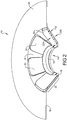
Figure 2 is a cross-sectional perspective view of the adjustable base plate shown inFigure 1 of the present disclosure; -
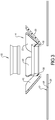
Figure 3 is a cross-sectional view of the base component of the adjustable base plate shown inFigure 1 of the present disclosure; -
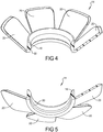
Figure 4 is a cross-sectional top perspective view of the base component of the adjustable base plate shown inFigure 1 of the present disclosure; and -
Figure 5 is a cross-sectional bottom perspective view of the base component of the adjustable base plate shown inFigure 1 of the present disclosure. - Corresponding reference numerals indicate corresponding parts throughout the several views of the drawings.
- Example embodiments will now be described more fully with reference to the accompanying drawings.
- Example embodiments are provided so that this disclosure will be thorough, and will fully convey the scope to those who are skilled in the art. Numerous specific details are set forth such as examples of specific components, devices, and methods, to provide a thorough understanding of embodiments of the present disclosure. It will be apparent to those skilled in the art that specific details need not be employed, that example embodiments may be embodied in many different forms and that neither should be construed to limit the scope of the disclosure. In some example embodiments, well-known processes, well-known device structures, and well-known technologies are not described in detail.
- The terminology used herein is for the purpose of describing particular example embodiments only and is not intended to be limiting. As used herein, the singular forms "a," "an," and "the" may be intended to include the plural forms as well, unless the context clearly indicates otherwise. The terms "comprises," "comprising," "including," and "having," are inclusive and therefore specify the presence of stated features, integers, steps, operations, elements, and/or components, but do not preclude the presence or addition of one or more other features, integers, steps, operations, elements, components, and/or groups thereof. The method steps, processes, and operations described herein are not to be construed as necessarily requiring their performance in the particular order discussed or illustrated, unless specifically identified as an order of performance. It is also to be understood that additional or alternative steps may be employed.
- When an element or layer is referred to as being "on," "engaged to," "connected to," or "coupled to" another element or layer, it may be directly on, engaged, connected or coupled to the other element or layer, or intervening elements or layers may be present. In contrast, when an element is referred to as being "directly on," "directly engaged to," "directly connected to," or "directly coupled to" another element or layer, there may be no intervening elements or layers present. Other words used to describe the relationship between elements should be interpreted in a like fashion (e.g., "between" versus "directly between," "adjacent" versus "directly adjacent," etc.). As used herein, the term "and/or" includes any and all combinations of one or more of the associated listed items.
- Although the terms first, second, third, etc. may be used herein to describe various elements, components, regions, layers and/or sections, these elements, components, regions, layers and/or sections should not be limited by these terms. These terms may be only used to distinguish one element, component, region, layer or section from another region, layer or section. Terms such as "first," "second," and other numerical terms when used herein do not imply a sequence or order unless clearly indicated by the context. Thus, a first element, component, region, layer or section discussed below could be termed a second element, heat and moisture exchange component, region, layer or section without departing from the teachings of the example embodiments.
- Spatially relative terms, such as "inner," "outer," "beneath," "below," "lower," "above," "upper," and the like, may be used herein for ease of description to describe one element or feature's relationship to another element(s) or feature(s) as illustrated in the figures. Spatially relative terms may be intended to encompass different orientations of the device in use or operation in addition to the orientation depicted in the figures. For example, if the device in the figures is turned over, elements described as "below" or "beneath" other elements or features would then be oriented "above" the other elements or features. Thus, the example term "below" can encompass both an orientation of above and below. The device may be otherwise oriented (rotated 90 degrees or at other orientations) and the spatially relative descriptors used herein interpreted accordingly.
- With reference to
Figure 1 , anadjustable base plate 10 for use with a tracheotomy stoma will now be described. Theadjustable base plate 10 includes aflexible membrane 12 and abase component 14 bonded to theflexible membrane 12. Thebase component 14 and theflexible membrane 12 can be bonded together by a laser weld, heat weld, RF weld, or by the use of an adhesive, or other known bonding techniques. Theflexible membrane 12 can be made from a polyurethane film or other similar material and can be formed as a flat disk with anopening 16 in a center. - The base component 14 (best shown in cross-section in
Figures 3-5 ) includes a generally cylindricalaccessory mounting portion 18 and a plurality of conformingmembers 20 extending radially outwardly from theaccessory mounting portion 18. The plurality of conformingmembers 20 are angled relative to theaccessory mounting portion 18 so as to combine with theflexible membrane 12 to form a centralconical region 22 of theadjustable base plate 10 surrounding theaccessory mounting portion 18. The conformingmembers 20 are angled so as to provide better retention in the tracheostoma and resist outward forces exerted during use with tracheostoma accessories. Theflexible membrane 12 further defines a generallyplanar region 24 that extends radially outward from the centralconical region 22. The generallyplanar region 24 and the centralconical region 22 can be coated with anadhesive material 28. A release liner 26 (shown partially peeled away inFigure 1 ) can be adhered to theflexible membrane 12 to cover theadhesive material 28 during handling and can be removed to expose theadhesive material 28 prior to application to a tracheostoma. - The
base component 14 can be made from a polyurethane or other similar material and preferably have a more rigid construction than theflexible membrane 12. Theaccessory mounting portion 18 can include aretention shoulder 30 that can retain anaccessory 32 in connection with theaccessory mounting portion 18. The accessories can include a heat and moisture exchanger (HME), a valve, a hands free valve, a shower guard or other known tracheostoma accessory which can be disposed in a housing that is engaged with theaccessory mounting portion 18. Other retention features such as magnets, press fit, snap features or other known retention features can be used. - The central
conical region 22 of theadjustable base plate 10 is formed with theflexible membrane 12 defining a plurality ofweb regions 34 between the conformingmembers 20. The conformingmembers 20 can resemble petals extending radially outwardly from the cylindricalaccessory mounting portion 18. Theconical region 22 defines a conicalinternal surface 22A and a conicalexternal surface 22B with theaccessory mounting portion 18 extending from theconical region 22. The thin film of theweb regions 34 allow for the conical external surface of theconical region 22 to conform to different depths of tracheostomas as well as non-symmetrical geometries around the tracheostoma for creating a better seal than conventional flat base plate components. The conformingmembers 20 tend to remain adhered to the tracheostoma and adapt to the natural movement of the peristomal skin. - The plurality of conforming
members 20 can include between three and fifteen conforming members that can be generally rectangular, triangular or trapezoidal in shape. In the example shown inFigure 1 , seven conforming members are shown. Theweb regions 34 between the conforming members can be generally triangular, rectangular or trapezoidal in shape. The conformingmembers 20 can all be similarly shaped and sized or can have differing shapes or sizes. - The foregoing description of the embodiments has been provided for purposes of illustration and description. It is not intended to be exhaustive or to limit the disclosure. Individual elements or features of a particular embodiment are generally not limited to that particular embodiment, but, where applicable, are interchangeable and can be used in a selected embodiment, even if not specifically shown or described. The same may also be varied in many ways. Such variations are not to be regarded as a departure from the disclosure, and all such modifications are intended to be included within the scope of the disclosure.
Claims (7)
- An adjustable base plate (10) for use with a tracheostoma comprising:a flexible membrane (12);an adhesive material (28) applied to the flexible membrane (12); anda base component (14) bonded to the flexible membrane (12) and including an accessory mounting portion (18) disposed in a center of the flexible membrane (12) and adapted to mount a tracheostoma accessory, characterized in thata plurality of conforming members (20) extend radially outward from and are angled relative to the accessory mounting portion (18) and are bonded to the flexible membrane (12) to define a conically shaped region with the conforming members (20) laterally spaced from one another, wherein the plurality of conforming members (20) are configured to conform to the surface around the tracheostoma the flexible membrane (12) is adhered to.
- The base plate according to claim 1, wherein the conforming members (20) are generally rectangular.
- The base plate according to claim 1, wherein the conforming members (20) are generally trapezoidal.
- The base plate according to any of the preceding claims, wherein the base component (14) is made from one of polyurethane, ethylene vinyl acetate (EVA), polyvinyl chloride (PVC), silicone, or polyethylene.
- The base plate according to any of the preceding claims, wherein the flexible membrane (12) is elastic and is made from one of polyurethane, ethylene vinyl acetate (EVA), polyvinyl chloride (PVC), silicone, or polyethylene.
- The base plate according to any of the preceding claims, wherein the accessory mounting portion (18) is generally cylindrical in shape.
- The base plate according to any of the preceding claims, wherein the conically shaped region (22) has an inner conical surface (22A) and an outer conical surface (22B) and the accessory mounting portion (18) extends from the conically shaped region.
Applications Claiming Priority (1)
| Application Number | Priority Date | Filing Date | Title |
|---|---|---|---|
| US15/824,594 US10646332B2 (en) | 2017-11-28 | 2017-11-28 | Adjustable baseplate for use with irregular tracheostomas |
Publications (2)
| Publication Number | Publication Date |
|---|---|
| EP3488888A1 EP3488888A1 (en) | 2019-05-29 |
| EP3488888B1 true EP3488888B1 (en) | 2021-06-09 |
Family
ID=63077710
Family Applications (1)
| Application Number | Title | Priority Date | Filing Date |
|---|---|---|---|
| EP18185657.6A Active EP3488888B1 (en) | 2017-11-28 | 2018-07-26 | Adjustable baseplate for use with irregular tracheostomas |
Country Status (2)
| Country | Link |
|---|---|
| US (1) | US10646332B2 (en) |
| EP (1) | EP3488888B1 (en) |
Families Citing this family (3)
| Publication number | Priority date | Publication date | Assignee | Title |
|---|---|---|---|---|
| DE102014018678B4 (en) * | 2014-12-18 | 2021-11-11 | Andreas Fahl Medizintechnik-Vertrieb Gmbh | Tracheostoma protection |
| JP2023012860A (en) * | 2021-07-14 | 2023-01-26 | 国立大学法人千葉大学 | cannula protection assembly |
| CA3214382C (en) | 2022-09-01 | 2024-04-30 | James P. WINES | Ostomy appliance with customizable barrier ring for localized convex support |
Family Cites Families (9)
| Publication number | Priority date | Publication date | Assignee | Title |
|---|---|---|---|---|
| US7025784B1 (en) | 1981-10-29 | 2006-04-11 | Hansa Medical Products, Inc. | Method and apparatus for a tracheal valve |
| US20040204759A1 (en) * | 2001-12-28 | 2004-10-14 | Eric Blom | Prosthesis with foldable flange |
| SE0201907D0 (en) | 2002-06-19 | 2002-06-19 | Atos Medical Ab | Patches for tracheostoma valves |
| WO2010070087A2 (en) | 2008-12-19 | 2010-06-24 | Atos Medical Ab | Tracheostoma plaster |
| CN104822409B (en) | 2012-12-11 | 2018-09-14 | 阿托斯医疗公司 | Tracheostoma device retainer |
| GB2517680B (en) | 2013-07-23 | 2019-05-15 | Prosys Int Ltd | Tracheostomal plaster |
| US11433204B2 (en) | 2016-02-04 | 2022-09-06 | Atos Medical Ab | Tracheostoma device holder |
| USD847982S1 (en) | 2016-02-04 | 2019-05-07 | Atos Medical Ab | Heat exchanger base plate |
| US10980956B2 (en) | 2016-04-01 | 2021-04-20 | Atos Medical Ab | Tracheostoma valve |
-
2017
- 2017-11-28 US US15/824,594 patent/US10646332B2/en active Active
-
2018
- 2018-07-26 EP EP18185657.6A patent/EP3488888B1/en active Active
Also Published As
| Publication number | Publication date |
|---|---|
| US20190159892A1 (en) | 2019-05-30 |
| US10646332B2 (en) | 2020-05-12 |
| EP3488888A1 (en) | 2019-05-29 |
Similar Documents
| Publication | Publication Date | Title |
|---|---|---|
| US10973676B2 (en) | Mounting assemblies for ostomy appliances comprising an adhesive skin barrier member having a multi-petaled outer perimeter | |
| US10945873B2 (en) | Multi-petaled mounting members for ostomy pouches | |
| CN102781376B (en) | Ostomy appliance | |
| EP2280673B1 (en) | Locating flange for a two-piece ostomy adhesive mount | |
| US6869422B2 (en) | Ostomy pouch and method of assembly | |
| JP6262531B2 (en) | Elastic strip | |
| EP3054906B1 (en) | Flange extender for an ostomy bag | |
| EP2750724B1 (en) | Skin contact material | |
| US9622903B2 (en) | Ostomy appliance | |
| JP5567614B2 (en) | Convex protection ring | |
| US20200316290A1 (en) | Injection device with adhesive assembly | |
| EP4119112A1 (en) | Moldable adhesive wafers | |
| EP3488888A1 (en) | Adjustable baseplate for use with irregular tracheostomas | |
| ATE355867T1 (en) | PLASTERS FOR TRACHEOSTOMA VALVE | |
| DK1413268T3 (en) | An ostomy appliance | |
| EP2429466B1 (en) | Ostomy appliance coupling system | |
| WO2004062537A1 (en) | A support for an ostomy bag | |
| US20110118684A1 (en) | Adhesive ostomy coupling | |
| US10420671B2 (en) | Ostomy pouch assembly | |
| US10390760B2 (en) | Carrier system for a medical device worn on the body | |
| WO2016196120A1 (en) | Ostomy appliance with fastening pads and related methods | |
| WO2019058088A2 (en) | Perspiration shield | |
| JP2007330371A (en) | Contact grain patching sheet for treatment |
Legal Events
| Date | Code | Title | Description |
|---|---|---|---|
| PUAI | Public reference made under article 153(3) epc to a published international application that has entered the european phase |
Free format text: ORIGINAL CODE: 0009012 |
|
| STAA | Information on the status of an ep patent application or granted ep patent |
Free format text: STATUS: REQUEST FOR EXAMINATION WAS MADE |
|
| 17P | Request for examination filed |
Effective date: 20180824 |
|
| AK | Designated contracting states |
Kind code of ref document: A1 Designated state(s): AL AT BE BG CH CY CZ DE DK EE ES FI FR GB GR HR HU IE IS IT LI LT LU LV MC MK MT NL NO PL PT RO RS SE SI SK SM TR |
|
| AX | Request for extension of the european patent |
Extension state: BA ME |
|
| RBV | Designated contracting states (corrected) |
Designated state(s): AL AT BE BG CH CY CZ DE DK EE ES FI FR GB GR HR HU IE IS IT LI LT LU LV MC MK MT NL NO PL PT RO RS SE SI SK SM TR |
|
| RIC1 | Information provided on ipc code assigned before grant |
Ipc: A61F 13/12 20060101ALI20210128BHEP Ipc: A61M 16/04 20060101AFI20210128BHEP |
|
| GRAP | Despatch of communication of intention to grant a patent |
Free format text: ORIGINAL CODE: EPIDOSNIGR1 |
|
| STAA | Information on the status of an ep patent application or granted ep patent |
Free format text: STATUS: GRANT OF PATENT IS INTENDED |
|
| INTG | Intention to grant announced |
Effective date: 20210317 |
|
| GRAS | Grant fee paid |
Free format text: ORIGINAL CODE: EPIDOSNIGR3 |
|
| GRAA | (expected) grant |
Free format text: ORIGINAL CODE: 0009210 |
|
| STAA | Information on the status of an ep patent application or granted ep patent |
Free format text: STATUS: THE PATENT HAS BEEN GRANTED |
|
| AK | Designated contracting states |
Kind code of ref document: B1 Designated state(s): AL AT BE BG CH CY CZ DE DK EE ES FI FR GB GR HR HU IE IS IT LI LT LU LV MC MK MT NL NO PL PT RO RS SE SI SK SM TR |
|
| REG | Reference to a national code |
Ref country code: GB Ref legal event code: FG4D |
|
| REG | Reference to a national code |
Ref country code: CH Ref legal event code: EP Ref country code: AT Ref legal event code: REF Ref document number: 1399952 Country of ref document: AT Kind code of ref document: T Effective date: 20210615 |
|
| REG | Reference to a national code |
Ref country code: DE Ref legal event code: R096 Ref document number: 602018018270 Country of ref document: DE |
|
| REG | Reference to a national code |
Ref country code: IE Ref legal event code: FG4D |
|
| REG | Reference to a national code |
Ref country code: LT Ref legal event code: MG9D |
|
| PG25 | Lapsed in a contracting state [announced via postgrant information from national office to epo] |
Ref country code: HR Free format text: LAPSE BECAUSE OF FAILURE TO SUBMIT A TRANSLATION OF THE DESCRIPTION OR TO PAY THE FEE WITHIN THE PRESCRIBED TIME-LIMIT Effective date: 20210609 Ref country code: LT Free format text: LAPSE BECAUSE OF FAILURE TO SUBMIT A TRANSLATION OF THE DESCRIPTION OR TO PAY THE FEE WITHIN THE PRESCRIBED TIME-LIMIT Effective date: 20210609 Ref country code: FI Free format text: LAPSE BECAUSE OF FAILURE TO SUBMIT A TRANSLATION OF THE DESCRIPTION OR TO PAY THE FEE WITHIN THE PRESCRIBED TIME-LIMIT Effective date: 20210609 Ref country code: BG Free format text: LAPSE BECAUSE OF FAILURE TO SUBMIT A TRANSLATION OF THE DESCRIPTION OR TO PAY THE FEE WITHIN THE PRESCRIBED TIME-LIMIT Effective date: 20210909 |
|
| REG | Reference to a national code |
Ref country code: AT Ref legal event code: MK05 Ref document number: 1399952 Country of ref document: AT Kind code of ref document: T Effective date: 20210609 |
|
| REG | Reference to a national code |
Ref country code: NL Ref legal event code: MP Effective date: 20210609 |
|
| PG25 | Lapsed in a contracting state [announced via postgrant information from national office to epo] |
Ref country code: RS Free format text: LAPSE BECAUSE OF FAILURE TO SUBMIT A TRANSLATION OF THE DESCRIPTION OR TO PAY THE FEE WITHIN THE PRESCRIBED TIME-LIMIT Effective date: 20210609 Ref country code: SE Free format text: LAPSE BECAUSE OF FAILURE TO SUBMIT A TRANSLATION OF THE DESCRIPTION OR TO PAY THE FEE WITHIN THE PRESCRIBED TIME-LIMIT Effective date: 20210609 Ref country code: LV Free format text: LAPSE BECAUSE OF FAILURE TO SUBMIT A TRANSLATION OF THE DESCRIPTION OR TO PAY THE FEE WITHIN THE PRESCRIBED TIME-LIMIT Effective date: 20210609 Ref country code: NO Free format text: LAPSE BECAUSE OF FAILURE TO SUBMIT A TRANSLATION OF THE DESCRIPTION OR TO PAY THE FEE WITHIN THE PRESCRIBED TIME-LIMIT Effective date: 20210909 Ref country code: GR Free format text: LAPSE BECAUSE OF FAILURE TO SUBMIT A TRANSLATION OF THE DESCRIPTION OR TO PAY THE FEE WITHIN THE PRESCRIBED TIME-LIMIT Effective date: 20210910 |
|
| PG25 | Lapsed in a contracting state [announced via postgrant information from national office to epo] |
Ref country code: NL Free format text: LAPSE BECAUSE OF FAILURE TO SUBMIT A TRANSLATION OF THE DESCRIPTION OR TO PAY THE FEE WITHIN THE PRESCRIBED TIME-LIMIT Effective date: 20210609 Ref country code: PT Free format text: LAPSE BECAUSE OF FAILURE TO SUBMIT A TRANSLATION OF THE DESCRIPTION OR TO PAY THE FEE WITHIN THE PRESCRIBED TIME-LIMIT Effective date: 20211011 Ref country code: RO Free format text: LAPSE BECAUSE OF FAILURE TO SUBMIT A TRANSLATION OF THE DESCRIPTION OR TO PAY THE FEE WITHIN THE PRESCRIBED TIME-LIMIT Effective date: 20210609 Ref country code: AT Free format text: LAPSE BECAUSE OF FAILURE TO SUBMIT A TRANSLATION OF THE DESCRIPTION OR TO PAY THE FEE WITHIN THE PRESCRIBED TIME-LIMIT Effective date: 20210609 Ref country code: CZ Free format text: LAPSE BECAUSE OF FAILURE TO SUBMIT A TRANSLATION OF THE DESCRIPTION OR TO PAY THE FEE WITHIN THE PRESCRIBED TIME-LIMIT Effective date: 20210609 Ref country code: SM Free format text: LAPSE BECAUSE OF FAILURE TO SUBMIT A TRANSLATION OF THE DESCRIPTION OR TO PAY THE FEE WITHIN THE PRESCRIBED TIME-LIMIT Effective date: 20210609 Ref country code: SK Free format text: LAPSE BECAUSE OF FAILURE TO SUBMIT A TRANSLATION OF THE DESCRIPTION OR TO PAY THE FEE WITHIN THE PRESCRIBED TIME-LIMIT Effective date: 20210609 Ref country code: ES Free format text: LAPSE BECAUSE OF FAILURE TO SUBMIT A TRANSLATION OF THE DESCRIPTION OR TO PAY THE FEE WITHIN THE PRESCRIBED TIME-LIMIT Effective date: 20210609 Ref country code: EE Free format text: LAPSE BECAUSE OF FAILURE TO SUBMIT A TRANSLATION OF THE DESCRIPTION OR TO PAY THE FEE WITHIN THE PRESCRIBED TIME-LIMIT Effective date: 20210609 |
|
| PG25 | Lapsed in a contracting state [announced via postgrant information from national office to epo] |
Ref country code: PL Free format text: LAPSE BECAUSE OF FAILURE TO SUBMIT A TRANSLATION OF THE DESCRIPTION OR TO PAY THE FEE WITHIN THE PRESCRIBED TIME-LIMIT Effective date: 20210609 |
|
| REG | Reference to a national code |
Ref country code: CH Ref legal event code: PL |
|
| REG | Reference to a national code |
Ref country code: DE Ref legal event code: R097 Ref document number: 602018018270 Country of ref document: DE |
|
| PG25 | Lapsed in a contracting state [announced via postgrant information from national office to epo] |
Ref country code: MC Free format text: LAPSE BECAUSE OF FAILURE TO SUBMIT A TRANSLATION OF THE DESCRIPTION OR TO PAY THE FEE WITHIN THE PRESCRIBED TIME-LIMIT Effective date: 20210609 |
|
| REG | Reference to a national code |
Ref country code: BE Ref legal event code: MM Effective date: 20210731 |
|
| PLBE | No opposition filed within time limit |
Free format text: ORIGINAL CODE: 0009261 |
|
| STAA | Information on the status of an ep patent application or granted ep patent |
Free format text: STATUS: NO OPPOSITION FILED WITHIN TIME LIMIT |
|
| PG25 | Lapsed in a contracting state [announced via postgrant information from national office to epo] |
Ref country code: LI Free format text: LAPSE BECAUSE OF NON-PAYMENT OF DUE FEES Effective date: 20210731 Ref country code: DK Free format text: LAPSE BECAUSE OF FAILURE TO SUBMIT A TRANSLATION OF THE DESCRIPTION OR TO PAY THE FEE WITHIN THE PRESCRIBED TIME-LIMIT Effective date: 20210609 Ref country code: CH Free format text: LAPSE BECAUSE OF NON-PAYMENT OF DUE FEES Effective date: 20210731 |
|
| 26N | No opposition filed |
Effective date: 20220310 |
|
| PG25 | Lapsed in a contracting state [announced via postgrant information from national office to epo] |
Ref country code: LU Free format text: LAPSE BECAUSE OF NON-PAYMENT OF DUE FEES Effective date: 20210726 Ref country code: AL Free format text: LAPSE BECAUSE OF FAILURE TO SUBMIT A TRANSLATION OF THE DESCRIPTION OR TO PAY THE FEE WITHIN THE PRESCRIBED TIME-LIMIT Effective date: 20210609 |
|
| PG25 | Lapsed in a contracting state [announced via postgrant information from national office to epo] |
Ref country code: IT Free format text: LAPSE BECAUSE OF FAILURE TO SUBMIT A TRANSLATION OF THE DESCRIPTION OR TO PAY THE FEE WITHIN THE PRESCRIBED TIME-LIMIT Effective date: 20210609 Ref country code: IE Free format text: LAPSE BECAUSE OF NON-PAYMENT OF DUE FEES Effective date: 20210726 Ref country code: BE Free format text: LAPSE BECAUSE OF NON-PAYMENT OF DUE FEES Effective date: 20210731 |
|
| P01 | Opt-out of the competence of the unified patent court (upc) registered |
Effective date: 20230515 |
|
| PG25 | Lapsed in a contracting state [announced via postgrant information from national office to epo] |
Ref country code: CY Free format text: LAPSE BECAUSE OF FAILURE TO SUBMIT A TRANSLATION OF THE DESCRIPTION OR TO PAY THE FEE WITHIN THE PRESCRIBED TIME-LIMIT Effective date: 20210609 |
|
| PG25 | Lapsed in a contracting state [announced via postgrant information from national office to epo] |
Ref country code: HU Free format text: LAPSE BECAUSE OF FAILURE TO SUBMIT A TRANSLATION OF THE DESCRIPTION OR TO PAY THE FEE WITHIN THE PRESCRIBED TIME-LIMIT; INVALID AB INITIO Effective date: 20180726 |
|
| PG25 | Lapsed in a contracting state [announced via postgrant information from national office to epo] |
Ref country code: MK Free format text: LAPSE BECAUSE OF FAILURE TO SUBMIT A TRANSLATION OF THE DESCRIPTION OR TO PAY THE FEE WITHIN THE PRESCRIBED TIME-LIMIT Effective date: 20210609 |
|
| PG25 | Lapsed in a contracting state [announced via postgrant information from national office to epo] |
Ref country code: MT Free format text: LAPSE BECAUSE OF FAILURE TO SUBMIT A TRANSLATION OF THE DESCRIPTION OR TO PAY THE FEE WITHIN THE PRESCRIBED TIME-LIMIT Effective date: 20210609 |
|
| PGFP | Annual fee paid to national office [announced via postgrant information from national office to epo] |
Ref country code: DE Payment date: 20250730 Year of fee payment: 8 |
|
| PGFP | Annual fee paid to national office [announced via postgrant information from national office to epo] |
Ref country code: GB Payment date: 20250725 Year of fee payment: 8 |
|
| PGFP | Annual fee paid to national office [announced via postgrant information from national office to epo] |
Ref country code: FR Payment date: 20250729 Year of fee payment: 8 |
|
| PG25 | Lapsed in a contracting state [announced via postgrant information from national office to epo] |
Ref country code: TR Free format text: LAPSE BECAUSE OF FAILURE TO SUBMIT A TRANSLATION OF THE DESCRIPTION OR TO PAY THE FEE WITHIN THE PRESCRIBED TIME-LIMIT Effective date: 20210609 |