EP3488763A1 - Line-of-sight detection device, line-of-sight detection method, and computer program - Google Patents
Line-of-sight detection device, line-of-sight detection method, and computer program Download PDFInfo
- Publication number
- EP3488763A1 EP3488763A1 EP17843173.0A EP17843173A EP3488763A1 EP 3488763 A1 EP3488763 A1 EP 3488763A1 EP 17843173 A EP17843173 A EP 17843173A EP 3488763 A1 EP3488763 A1 EP 3488763A1
- Authority
- EP
- European Patent Office
- Prior art keywords
- image
- light source
- subject
- line
- light
- Prior art date
- Legal status (The legal status is an assumption and is not a legal conclusion. Google has not performed a legal analysis and makes no representation as to the accuracy of the status listed.)
- Granted
Links
Images








Classifications
-
- G—PHYSICS
- G06—COMPUTING OR CALCULATING; COUNTING
- G06T—IMAGE DATA PROCESSING OR GENERATION, IN GENERAL
- G06T7/00—Image analysis
- G06T7/70—Determining position or orientation of objects or cameras
- G06T7/73—Determining position or orientation of objects or cameras using feature-based methods
-
- A—HUMAN NECESSITIES
- A61—MEDICAL OR VETERINARY SCIENCE; HYGIENE
- A61B—DIAGNOSIS; SURGERY; IDENTIFICATION
- A61B3/00—Apparatus for testing the eyes; Instruments for examining the eyes
- A61B3/0008—Apparatus for testing the eyes; Instruments for examining the eyes provided with illuminating means
-
- A—HUMAN NECESSITIES
- A61—MEDICAL OR VETERINARY SCIENCE; HYGIENE
- A61B—DIAGNOSIS; SURGERY; IDENTIFICATION
- A61B3/00—Apparatus for testing the eyes; Instruments for examining the eyes
- A61B3/10—Objective types, i.e. instruments for examining the eyes independent of the patients' perceptions or reactions
- A61B3/113—Objective types, i.e. instruments for examining the eyes independent of the patients' perceptions or reactions for determining or recording eye movement
-
- A—HUMAN NECESSITIES
- A61—MEDICAL OR VETERINARY SCIENCE; HYGIENE
- A61B—DIAGNOSIS; SURGERY; IDENTIFICATION
- A61B3/00—Apparatus for testing the eyes; Instruments for examining the eyes
- A61B3/10—Objective types, i.e. instruments for examining the eyes independent of the patients' perceptions or reactions
- A61B3/14—Arrangements specially adapted for eye photography
- A61B3/15—Arrangements specially adapted for eye photography with means for aligning, spacing or blocking spurious reflection ; with means for relaxing
- A61B3/152—Arrangements specially adapted for eye photography with means for aligning, spacing or blocking spurious reflection ; with means for relaxing for aligning
-
- G—PHYSICS
- G06—COMPUTING OR CALCULATING; COUNTING
- G06T—IMAGE DATA PROCESSING OR GENERATION, IN GENERAL
- G06T1/00—General purpose image data processing
-
- G—PHYSICS
- G06—COMPUTING OR CALCULATING; COUNTING
- G06V—IMAGE OR VIDEO RECOGNITION OR UNDERSTANDING
- G06V10/00—Arrangements for image or video recognition or understanding
- G06V10/10—Image acquisition
- G06V10/12—Details of acquisition arrangements; Constructional details thereof
- G06V10/14—Optical characteristics of the device performing the acquisition or on the illumination arrangements
- G06V10/141—Control of illumination
-
- G—PHYSICS
- G06—COMPUTING OR CALCULATING; COUNTING
- G06V—IMAGE OR VIDEO RECOGNITION OR UNDERSTANDING
- G06V40/00—Recognition of biometric, human-related or animal-related patterns in image or video data
- G06V40/10—Human or animal bodies, e.g. vehicle occupants or pedestrians; Body parts, e.g. hands
- G06V40/16—Human faces, e.g. facial parts, sketches or expressions
- G06V40/161—Detection; Localisation; Normalisation
-
- G—PHYSICS
- G06—COMPUTING OR CALCULATING; COUNTING
- G06V—IMAGE OR VIDEO RECOGNITION OR UNDERSTANDING
- G06V40/00—Recognition of biometric, human-related or animal-related patterns in image or video data
- G06V40/10—Human or animal bodies, e.g. vehicle occupants or pedestrians; Body parts, e.g. hands
- G06V40/16—Human faces, e.g. facial parts, sketches or expressions
- G06V40/161—Detection; Localisation; Normalisation
- G06V40/166—Detection; Localisation; Normalisation using acquisition arrangements
-
- G—PHYSICS
- G06—COMPUTING OR CALCULATING; COUNTING
- G06V—IMAGE OR VIDEO RECOGNITION OR UNDERSTANDING
- G06V40/00—Recognition of biometric, human-related or animal-related patterns in image or video data
- G06V40/10—Human or animal bodies, e.g. vehicle occupants or pedestrians; Body parts, e.g. hands
- G06V40/18—Eye characteristics, e.g. of the iris
- G06V40/19—Sensors therefor
-
- G—PHYSICS
- G06—COMPUTING OR CALCULATING; COUNTING
- G06V—IMAGE OR VIDEO RECOGNITION OR UNDERSTANDING
- G06V40/00—Recognition of biometric, human-related or animal-related patterns in image or video data
- G06V40/10—Human or animal bodies, e.g. vehicle occupants or pedestrians; Body parts, e.g. hands
- G06V40/18—Eye characteristics, e.g. of the iris
- G06V40/193—Preprocessing; Feature extraction
-
- G—PHYSICS
- G09—EDUCATION; CRYPTOGRAPHY; DISPLAY; ADVERTISING; SEALS
- G09G—ARRANGEMENTS OR CIRCUITS FOR CONTROL OF INDICATING DEVICES USING STATIC MEANS TO PRESENT VARIABLE INFORMATION
- G09G5/00—Control arrangements or circuits for visual indicators common to cathode-ray tube indicators and other visual indicators
- G09G5/003—Details of a display terminal, the details relating to the control arrangement of the display terminal and to the interfaces thereto
-
- H—ELECTRICITY
- H04—ELECTRIC COMMUNICATION TECHNIQUE
- H04N—PICTORIAL COMMUNICATION, e.g. TELEVISION
- H04N23/00—Cameras or camera modules comprising electronic image sensors; Control thereof
-
- H—ELECTRICITY
- H04—ELECTRIC COMMUNICATION TECHNIQUE
- H04N—PICTORIAL COMMUNICATION, e.g. TELEVISION
- H04N23/00—Cameras or camera modules comprising electronic image sensors; Control thereof
- H04N23/70—Circuitry for compensating brightness variation in the scene
- H04N23/73—Circuitry for compensating brightness variation in the scene by influencing the exposure time
-
- G—PHYSICS
- G06—COMPUTING OR CALCULATING; COUNTING
- G06T—IMAGE DATA PROCESSING OR GENERATION, IN GENERAL
- G06T2207/00—Indexing scheme for image analysis or image enhancement
- G06T2207/30—Subject of image; Context of image processing
- G06T2207/30196—Human being; Person
- G06T2207/30201—Face
-
- G—PHYSICS
- G09—EDUCATION; CRYPTOGRAPHY; DISPLAY; ADVERTISING; SEALS
- G09G—ARRANGEMENTS OR CIRCUITS FOR CONTROL OF INDICATING DEVICES USING STATIC MEANS TO PRESENT VARIABLE INFORMATION
- G09G2320/00—Control of display operating conditions
- G09G2320/06—Adjustment of display parameters
- G09G2320/0626—Adjustment of display parameters for control of overall brightness
-
- G—PHYSICS
- G09—EDUCATION; CRYPTOGRAPHY; DISPLAY; ADVERTISING; SEALS
- G09G—ARRANGEMENTS OR CIRCUITS FOR CONTROL OF INDICATING DEVICES USING STATIC MEANS TO PRESENT VARIABLE INFORMATION
- G09G2320/00—Control of display operating conditions
- G09G2320/06—Adjustment of display parameters
- G09G2320/0686—Adjustment of display parameters with two or more screen areas displaying information with different brightness or colours
-
- G—PHYSICS
- G09—EDUCATION; CRYPTOGRAPHY; DISPLAY; ADVERTISING; SEALS
- G09G—ARRANGEMENTS OR CIRCUITS FOR CONTROL OF INDICATING DEVICES USING STATIC MEANS TO PRESENT VARIABLE INFORMATION
- G09G2340/00—Aspects of display data processing
- G09G2340/10—Mixing of images, i.e. displayed pixel being the result of an operation, e.g. adding, on the corresponding input pixels
Definitions
- the present invention relates to a line-of-sight detection device, a method for detecting a line of sight, and a computer program.
- the corneal reflection method is a method for detecting a line of sight of a subject in which the subject is irradiated with infrared light emitted from a light source, an eye of the subject irradiated with the infrared light is captured by a camera, and a position of a pupil with respect to a corneal reflection image, which is a reflection image of a light source on a corneal surface, is detected.
- Patent Literature 1 Japanese Laid-open Patent Publication No. JP 2010-244156 A
- the infrared light emitted to the subject is reflected by the eyeglasses.
- the detection accuracy of the line of sight may be lowered.
- the reflection image of the light source on the eyeglasses and the eye of the subject overlap in the visual field area of the camera, it becomes difficult to detect the corneal reflection image and the pupil.
- the corneal reflection image and the pupil are not detected excellently, the detection accuracy of the line of sight of the subject is lowered.
- An object of the present embodiment is to provide a line-of-sight detection device, a method for detecting a line of sight, and a computer program capable of suppressing deterioration of detection accuracy of a line of sight of a subject wearing eyeglasses.
- a line-of-sight detection device comprising: an image data acquisition unit that acquires image data of a face of a subject irradiated with detection light emitted from a light source; a line-of-sight detection unit that detects a line of sight of the subject based on the image data; an image processing unit that performs image processing on the image data to generate a feature image of the face and an eyeglasses reflection image indicating a reflection image of the light source on eyeglasses worn on the face; and a display controller that causes a display device to display the feature image and the eyeglasses reflection image in a different display form in a composite image in which the feature image and the eyeglasses reflection image are combined.
- a line-of-sight detection device a method for detecting a line of sight, and a computer program capable of suppressing deterioration of detection accuracy of a line of sight of a subject wearing eyeglasses.
- a direction parallel to an X axis of a predetermined plane is defined as an X-axis direction
- a direction parallel to a Y axis of the predetermined plane orthogonal to the X axis is defined as a Y-axis direction
- a direction parallel to a Z axis orthogonal to each of the X axis and the Y axis is defined as a Z-axis direction.
- the predetermined plane includes an XY plane.
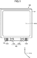
- FIG. 1 is a perspective view schematically illustrating an exemplary line-of-sight detection device 100 according to the present embodiment.
- the line-of-sight detection device 100 is used for, for example, a diagnostic support apparatus for supporting diagnosis of developmental disorder.
- the line-of-sight detection device 100 includes a display device 101, a stereo camera device 102, and a light source 103.
- the display device 100 includes a flat panel display such as a liquid crystal display (LCD) and an organic electroluminescence display (OELD).
- a flat panel display such as a liquid crystal display (LCD) and an organic electroluminescence display (OELD).
- LCD liquid crystal display
- OELD organic electroluminescence display
- a display screen 101S of the display device 100 is substantially parallel to the XY plane.
- the X-axis direction is a horizontal direction of the display screen 101S
- the Y-axis direction is a vertical direction of the display screen 101S
- the Z-axis direction is a depth direction orthogonal to the display screen 101S.
- the stereo camera device 102 takes an image of a subject and obtains image data of the subject.
- the stereo camera device 102 includes a first camera 102A and a second camera 102B, which are disposed at different positions.
- the stereo camera device 102 is disposed below the display screen 101S of the display device 101.
- the first camera 102A and the second camera 102B are disposed in the X-axis direction.
- the first camera 102A is disposed in the -X direction with respect to the second camera 102B.
- Each of the first camera 102A and the second camera 102B includes an infrared camera, and has, for example, an optical system capable of transmitting near-infrared light with a wavelength of 850 nm and an imaging element capable of receiving the near-infrared light.
- the light source 103 emits detection light.
- the light source 103 includes a first light source 103A and a second light source 103B, which are disposed at different positions.
- the light source 103 is disposed below the display screen 101S of the display device 101.
- the first light source 103A and the second light source 103B are disposed in the X-axis direction.
- the first light source 103A is disposed in the -X direction with respect to the first camera 102A.
- the second light source 103B is disposed in the +X direction with respect to the second camera 102B.
- Each of the first light source 103A and the second light source 103B includes a light emitting diode (LED), and is capable of emitting near-infrared light with a wavelength of 850 nm, for example. Note that the first light source 103A and the second light source 103B may be disposed between the first camera 102A and the second camera 102B.
- LED light emitting diode
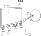
- FIG. 2 is a diagram schematically illustrating a positional relationship among the display device 101, the stereo camera device 102, the light source 103, and an eyeball 111 of the subject according to the present embodiment.
- the light source 103 emits infrared light as detection light to illuminate the eyeball 111 of the subject.
- the stereo camera device 102 takes an image of the eyeball 111 with the second camera 102B when the eyeball 111 is irradiated with the detection light emitted from the first light source 103A, and takes an image of the eyeball 111 with the first camera 102A when the eyeball 111 is irradiated with the detection light emitted from the second light source 103B.
- a frame synchronous signal is output from at least one of the first camera 102A and the second camera 102B.
- the first light source 103A and the second light source 103B emit the detection light based on the frame synchronous signal.
- the first camera 102A obtains image data of the eyeball 111.
- the second camera 102B obtains image data of the eyeball 111.
- a part of the detection light is reflected by a pupil 112.
- the light reflected by the pupil 112 enters the stereo camera device 102.
- a corneal reflection image 113 is formed on the eyeball 111.
- the corneal reflection image 113 is a reflection image of the light source 103 on a corneal surface. The light from the corneal reflection image 113 enters the stereo camera device 102.
- an intensity of the light entering the stereo camera device 102 from the pupil 112 decreases, and an intensity of the light entering the stereo camera device 102 from the corneal reflection image 113 increases. That is, the image of the pupil 112 obtained by the stereo camera device 102 has low luminance, and the image of the corneal reflection image 113 has high luminance.
- the stereo camera device 102 can detect a position of the pupil 112 and a position of the corneal reflection image 113 based on the luminance of the obtained images.
- FIG. 3 is a diagram illustrating an exemplary hardware configuration of the line-of-sight detection device 100 according to the present embodiment.
- the line-of-sight detection device 100 includes the display device 101, the stereo camera device 102, the light source 103, a computer system 20, an input/output interface device 30, a driving circuit 40, an output device 50, an input device 60, and a voice output device 70.
- the computer system 20 includes an arithmetic processing unit 20A and a storage unit 20B.
- a computer program 20C is stored in the storage unit 20B.
- the computer system 20, the driving circuit 40, the output device 50, the input device 60, and the voice output device 70 perform data communication via the input/output interface device 30.
- the arithmetic processing unit 20A includes a microprocessor such as a central processing unit (CPU).
- the storage unit 20B includes a nonvolatile memory such as a read-only memory (ROM), or a volatile memory such as a random access memory (RAM).
- the arithmetic processing unit 20A executes arithmetic processing according to the computer program 20C stored in the storage unit 20B.
- the driving circuit 40 generates a drive signal, and outputs it to the display device 101, the stereo camera device 102, and the light source 103. Further, the driving circuit 40 supplies the image data of the eyeball 111 obtained by the stereo camera device 102 to the computer system 20 via the input/output interface device 30.
- the output device 50 includes a display device such as a flat panel display. Note that the output device 50 may include a printer.
- the input device 60 generates input data by being operated.
- the input device 60 includes a keyboard or a mouse for a computer system. Note that the input device 60 may include a touch sensor provided on the display screen of the output device 50 that is the display device.
- the voice output device 70 includes a speaker, and outputs, for example, voice for calling the subject's attention.
- the display device 101 and the computer system 20 are separate devices. Note that the display device 101 and the computer system 20 may be integrated.
- the computer system 20, the input/output interface device 30, the driving circuit 40, and the display device 101 may be mounted on the tablet personal computer.
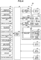
- FIG. 4 is a functional block diagram illustrating an example of the line-of-sight detection device 100 according to the present embodiment.
- the input/output interface device 30 includes an input/output unit 302.
- the driving circuit 40 includes a display device drive unit 402 that generates a drive signal for driving the display device 101 and outputs it to the display device 101, a first camera input/output unit 404A that generates a drive signal for driving the first camera 102A and outputs it to the first camera 102A, a second camera input/output unit 404B that generates a drive signal for driving the second camera 102B and outputs it to the second camera 102B, and a light source drive unit 406 that generates a drive signal for driving the first light source 103A and the second light source 103B and outputs it to the first light source 103A and the second light source 103B.
- first camera input/output unit 404A supplies the image data of the eyeball 111 obtained by the first camera 102A to the computer system 20 via the input/output unit 302.
- the second camera input/output unit 404B supplies the image data of the eyeball 111 obtained by the second camera 102B to the computer system 20 via the input/output unit 302.
- the computer system 20 controls the line-of-sight detection device 100.
- the computer system 20 includes an image data acquisition unit 202, an input data acquisition unit 204, an image processing unit 206, a display controller 208, a light source controller 210, a camera controller 211, a position detection unit 212, a curvature center calculation unit 214, a line-of-sight detection unit 216, a distance data acquisition unit 218, a storage 220, and an output controller 222.
- a function of the computer system 20 are performed by the arithmetic processing unit 20A, the storage unit 20B, and the computer program 20C stored in the storage unit 20B.
- the image data acquisition unit 202 acquires the image data of a face of the subject captured by the stereo camera device 102 including the first camera 102A and the second camera 102B from the stereo camera device 102 via the input/output unit 302.
- the image data is digital data.
- the image data of the face of the subject includes the image data of the eyeball 111.
- the stereo camera device 102 takes the image of the face of the subject to be irradiated with the detection light emitted from the light source 103.
- the image data acquisition unit 202 acquires the image data of the face of the subject to be irradiated with the detection light emitted from the light source 103 from the stereo camera device 102 via the input/output unit 302.
- the input data acquisition unit 204 acquires the input data generated by the input device 60 being operated from the input device 60 via the input/output unit 302.
- the image processing unit 206 performs image processing on the image data acquired by the image data acquisition unit 202.
- the image processing unit 206 performs the image processing on the image data, and generates a feature image indicating an image of a feature portion within the face of the subject, and generates an eyeglasses reflection image indicating a reflection image of the light source 103 on the eyeglasses worn on the face of the subject.
- the display controller 208 causes the display device 101 to display a specific image.
- the display controller 208 causes the display device 101 to display a composite image in which the feature image and the eyeglasses reflection image generated by the image processing unit 206 are combined.
- the display controller 208 causes the display device 101 to display the feature image and the eyeglasses reflection image in a different display form in the composite image in which the feature image and the eyeglasses reflection image are combined.
- the display form on the display device 101 includes at least one of luminance, color, lightness, and saturation of the image.
- the display controller 208 causes the display device 101 to display the eyeglasses reflection image in an emphasized manner compared with the feature image.
- the display controller 208 causes the display device 101 to display the eyeglasses reflection image with luminance higher than that of the feature image in the composite image.
- the display controller 208 may cause the display device 101 to display the eyeglasses reflection image with lightness higher than that of the feature image or with saturation higher than that of the feature image in the composite image.
- the light source controller 210 controls the light source drive unit 406 to control an operating state of the first light source 103A and the second light source 103B.
- the light source controller 210 controls the first light source 103A and the second light source 103B such that the first light source 103A and the second light source 103B emit the detection light at different timings. Further, the light source controller 210 controls the amount of light of the detection light emitted from the first light source 103A and the amount of light of the detection light emitted from the second light source 103B.
- the control of the amount of light of the detection light emitted from the first light source 103A includes at least one of control of light emission intensity of the first light source 103A and control of light emission time of the first light source 103A.
- control of the amount of light of the detection light emitted from the second light source 103B includes at least one of control of light emission intensity of the second light source 103B and control of light emission time of the second light source 103B.
- the light source controller 210 controls the first light source 103A and the second light source 103B such that the amount of light of the detection light emitted from the first light source 103A and the amount of light of the detection light emitted from the second light source 103B become the same amount.
- the camera controller 211 controls the first camera input/output unit 404A and the second camera input/output unit 404B to control an operating state of the stereo camera device 102 including the first camera 102A and the second camera 102B.
- the camera controller 211 controls an exposure value of the detection light in the first camera 102A and an exposure value of the detection light in the second camera 102B.
- Each of the exposure value of the detection light in the first and second cameras 102A and 102B indicates an exposure amount of the detection light entering the imaging element from the face of the subject illuminated with the detection light via each of an optical system of the first and second cameras 102A and 102B.
- a control of the exposure value of the detection light in the first and second cameras 102A and 102B includes at least one of a control of a shutter speed of the first and second cameras 102A and 102B and a control of an aperture value of the optical system of the first and second cameras 102A and 102B.
- the position detection unit 212 detects positional data of a pupil center based on the image data of the eyeball 111 acquired by the image data acquisition unit 202. Further, the position detection unit 212 detects positional data of a corneal reflection center based on the image data of the eyeball 111 acquired by the image data acquisition unit 202.
- the pupil center is a center of the pupil 112.
- the corneal reflection center is a center of the corneal reflection image 113.
- the position detection unit 212 detects the positional data of the pupil center and the positional data of the corneal reflection center with respect to each of the right and left eyeballs 111 of the subject.
- the curvature center calculation unit 214 calculates positional data of a corneal curvature center of the eyeball 111 based on the image data of the eyeball 111 acquired by the image data acquisition unit 202.
- the line-of-sight detection unit 216 detects a line of sight of the subject based on the image data of the eyeball 111 acquired by the image data acquisition unit 202.
- the line of sight of the subject includes a line-of-sight vector indicating a line-of-sight direction being observed by the subject.
- the line-of-sight detection unit 216 detects line-of-sight vectors of the right and left eyeballs 111 of the subject based on the positional data of the pupil center and the positional data of the corneal curvature center obtained from the image data of the eyeball 111.
- the line-of-sight detection unit 216 detects positional data of a gaze point of the subject based on the detected line-of-sight vector.
- the gaze point of the subject includes an intersection point of the line-of-sight vector of the subject and the display screen 101S of the display device 101.
- the positional data of the gaze point indicates positional data of the intersection point of the line-of-sight vector of the subject defined in the global coordinate system and the display screen 101S of the display device 101.
- the distance data acquisition unit 218 obtains distance data between the display screen 101S of the display device 101 and the face of the subject.
- the distance data acquisition unit 218 detects distance data based on the positional data of the pupil center detected by the position detection unit 212.
- the positional data of the pupil center in the global coordinate system is detected, whereby a distance between the center of the display screen 101S of the display device 101 and the eyeball 111 of the subject is calculated.
- the distance data acquisition unit 218 obtains the distance between the center of the display screen 101S of the display device 101 and the eyeball 111 of the subject as the distance data between the display screen 101S of the display device 101 and the face of the subject.
- the storage 220 stores the computer program 20C and various data.
- the output controller 222 outputs data to at least one of the display device 101, the output device 50, and the voice output device 70.
- the output controller 222 causes the display device 101 or the output device 50 to display the positional data of the gaze point of each of the right and left eyeballs 111 of the subject.
- the curvature center calculation unit 214 calculates the positional data of the corneal curvature center of the eyeball 111 based on the image data of the eyeball 111.
- FIGS. 5 and 6 are schematic diagrams for illustrating a method for calculating the positional data of the corneal curvature center 110 according to the present embodiment.
- FIG. 5 illustrates an exemplary case where the eyeball 111 is illuminated by one light source 103C.
- FIG. 6 illustrates an exemplary case where the eyeball 111 is illuminated by the first light source 103A and the second light source 103B.
- the light source 103C is disposed between the first camera 102A and the second camera 102B.
- a pupil center 112C is a center of the pupil 112.
- a corneal reflection center 113C is a center of the corneal reflection image 113.
- the pupil center 112C indicates the pupil center at the time when the eyeball 111 is illuminated by one light source 103C.
- the corneal reflection center 113C indicates the corneal reflection center at the time when the eyeball 111 is illuminated by one light source 103C.
- the corneal reflection center 113C exists on a straight line connecting the light source 103C and the corneal curvature center 110.
- the corneal reflection center 113C is positioned at a middle point between the corneal surface and the corneal curvature center 110.
- a corneal curvature radius 109 is a distance between the corneal surface and the corneal curvature center 110.
- Positional data of the corneal reflection center 113C is detected by the stereo camera device 102.
- the corneal curvature center 110 exists on a straight line connecting the light source 103C and the corneal reflection center 113C.
- the curvature center calculation unit 214 calculates positional data at which a distance from the corneal reflection center 113C on the straight line corresponds to a predetermined value as positional data of the corneal curvature center 110.
- the predetermined value is a value determined in advance from a general curvature radius value of the cornea, which is stored in the storage 220.
- the first camera 102A and the second light source 103B, and the second camera 102B and the first light source 103A are symmetrically disposed with respect to a straight line passing through an intermediate position between the first camera 102A and the second camera 102B. It can be assumed that a virtual light source 103V exists at the intermediate position between the first camera 102A and the second camera 102B.
- a corneal reflection center 121 indicates a corneal reflection center in the image of the eyeball 111 captured by the second camera 102B.
- a corneal reflection center 122 indicates a corneal reflection center in the image of the eyeball 111 captured by the first camera 102A.
- a corneal reflection center 124 indicates a corneal reflection center corresponding to the virtual light source 103V.
- Positional data of the corneal reflection center 124 is calculated based on positional data of the corneal reflection center 121 and positional data of the corneal reflection center 122 obtained by the stereo camera device 102.
- the stereo camera device 102 detects the positional data of the corneal reflection center 121 and the positional data of the corneal reflection center 122 in a local coordinate system defined by the stereo camera device 102.
- Camera calibration based on a stereo calibration method is performed on the stereo camera device 102 in advance, and a conversion parameter for converting the three-dimensional local coordinate system of the stereo camera device 102 into a three-dimensional global coordinate system is calculated.
- the conversion parameter is stored in the storage 220.
- the curvature center calculation unit 214 converts, using the conversion parameter, the positional data of the corneal reflection center 121 and the positional data of the corneal reflection center 122 obtained by the stereo camera device 102 into positional data in the global coordinate system.
- the curvature center calculation unit 214 calculates the positional data of the corneal reflection center 124 in the global coordinate system based on the positional data of the corneal reflection center 121 and the positional data of the corneal reflection center 122 defined in the global coordinate system.
- the corneal curvature center 110 exists on a straight line 123 connecting the virtual light source 103V and the corneal reflection center 124.
- the curvature center calculation unit 214 calculates positional data at which a distance from the corneal reflection center 124 on the straight line 123 corresponds to a predetermined value as positional data of the corneal curvature center 110.
- the predetermined value is a value determined in advance from a general curvature radius value of the cornea, which is stored in the storage 220.
- the corneal curvature center 110 is calculated according to the method similar to the method of a case where there is one light source.
- a corneal curvature radius 109 is a distance between the corneal surface and the corneal curvature center 110. Therefore, the corneal curvature radius 109 is calculated by calculating the positional data of the corneal surface and the positional data of the corneal curvature center 110.
- the positional data of the corneal curvature center 110, the positional data of the corneal reflection center 124, and the positional data of the pupil center 112C in the global coordinate system are calculated.
- the line-of-sight detection unit 216 is capable of detecting the line-of-sight vector of the subject based on the positional data of the pupil center 112C and the positional data of the corneal curvature center 110. Further, the distance data acquisition unit 218 is capable of obtaining the distance data between the display screen of the display device 101 and the face of the subject including the eyeball 111 based on the positional data of the pupil center 112C.
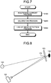
- FIG. 7 is a flowchart illustrating an example of a method for detecting a line of sight according to the present embodiment.
- a positioning support process for adjusting the line-of-sight detection device 100 and the subject to a proper relative position step S100
- a calibration process including processing for calculating the positional data of the corneal curvature center 110 and processing for calculating the distance data between the pupil center 112C and the corneal curvature center 110 step S200
- a line-of-sight detection process step S300
- FIG. 8 is a diagram schematically illustrating a relationship among the pupil 112 of the subject wearing eyeglasses 170, the stereo camera device 102, and the light source 103.
- FIG. 8 illustrates a state in which a position of a reflection image 172 of the light source 103 on the eyeglasses 170 and the position of the pupil 112 of the subject coincide with each other in the visual field area of the stereo camera device 102.
- FIG. 9 is a schematic view illustrating a state in which at least a part of the reflection image 172 of the light source 103 on the eyeglasses 170 overlaps the pupil 112 of the subject in the visual field area of the stereo camera device 102.
- the reflection image 172 of the light source 103 is formed on the lens of the eyeglasses 170, and in a case where the reflection image 172 and the pupil 112 of the subject overlap in the visual field area of the stereo camera device 102, it is difficult for the stereo camera device 102 to obtain image data of the pupil 112 of the subject and the corneal reflection image 113 excellently.
- the pupil 112 and the corneal reflection image 113 are not detected excellently, the detection accuracy of the line of sight of the subject is lowered.
- FIG. 10 is a schematic diagram illustrating a state in which the position of the reflection image 172 of the light source 103 on the eyeglasses 170 and the position of the pupil 112 of the subject do not coincide with each other in the visual field area of the stereo camera device 102.
- the stereo camera device 102 can obtain the image data of the pupil 112 of the subject and the corneal reflection image 113 excellently.
- the pupil 112 and the corneal reflection image 113 are detected excellently, a decrease in detection accuracy of the line of sight of the subject is suppressed.
- the line-of-sight detection device 100 supports the subject or a measurer such that the relative positions of the subject wearing the eyeglasses 170, the stereo camera device 102, and the light source 103 enter a state illustrated in FIG. 10 .
- the line-of-sight detection device 100 executes processing for prompting the subject or the measurer to adjust at least one of the position of the face of the subject, the orientation of the face, the position of the eyeglasses 170, and the orientation of the eyeglasses 170 so that the reflection image 172 and the eye of the subject do not overlap in the visual field area of the stereo camera device 102.
- FIG. 11 is a flowchart illustrating an exemplary positioning support process according to the present embodiment.
- the positioning support process includes a step for emitting the detection light from the light source 103 onto the face of the subject (step S101), a step for acquiring image data of the face of the subject irradiated with the detection light emitted from the light source 103 (step S102), a step for binarizing the obtained image data (step S103), a step for generating a feature image indicating an image of a feature portion within the face from the binarized image data (step S104), a step for adjusting luminance of the generated feature image (step S105), a step for generating an eyeglasses reflection image indicating the reflection image 172 of the light source 103 on the eyeglasses 170 worn on the face of the subject (step S106), a step for combining the feature image and the eyeglasses reflection image (step S107), and a step for causing the display device 101 to display a
- the light source 103 emits the detection light (step S101).
- the stereo camera device 102 obtains image data of the face of the subject onto which the detection light is emitted. At least one of the first camera 102A and the second camera 102B obtains the image data of the face of the subject.
- the first camera 102A obtains the image data of the face of the subject.
- the second camera 102B may obtain the image data of the face of the subject. Note that both the image data obtained by the first camera 102A and the image data obtained by the second camera 102B may be used.
- the image data acquisition unit 202 acquires the image data of the face of the subject onto which the detection light is emitted from the stereo camera device 102 (step S102).
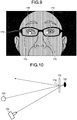
- FIG. 12 is a view schematically illustrating exemplary image data acquired by the image data acquisition unit 202 according to the present embodiment.
- FIG. 12 illustrates raw data that is image data before being subject to image processing, which is obtained by the stereo camera device 102 at the time when the infrared light as the detection light is emitted onto the face of the subject.
- the image processing unit 206 performs image processing on the image data acquired by the image data acquisition unit 202.
- the image processing unit 206 binarizes the image data acquired by the image data acquisition unit 202 (step S103).
- FIG. 13 is a view schematically illustrating exemplary binarized image data according to the present embodiment.
- the binarization of the image data indicates processing for converting the image data including a plurality of pixels into two tones of black and white based on a predetermined threshold value.
- the binarization is performed based on a predetermined first threshold value.
- the image processing unit 206 replaces the pixel with white color, and replaces the pixel with black color when the luminance of the pixel is lower than the first threshold value.
- the first threshold value in the binarization may be a fixed value set in advance, an intermediate value between the highest value and the lowest value among the luminance of the plurality of pixels of the obtained image data, or an intermediate value in luminance distribution.
- the binarization may be performed based on at least one of the P-tile method in which the first threshold value is determined according to a ratio of white pixels in the binarized result image, the modal method in which the bottom value of a valley of a histogram is set to the first threshold value when the luminance histogram has two maximum values, and the discriminant analysis method in which the first threshold value is determined such that, when the luminance histogram of the image is divided into two classes at a certain threshold value, the interclass variance becomes the largest.
- the image processing unit 206 generates, from the binarized image data, the feature image indicating the image of the feature portion within the face (step S104).
- the feature image includes a contour image of the face of the subject.
- FIG. 14 is a view schematically illustrating an exemplary contour image 174M of the face of the subject according to the present embodiment.
- the contour image 174M includes an edge image indicating a boundary between a white portion and a black portion of the binarized image data.
- the luminance of the contour image 174M generated in step S104 is equal to or higher than the first threshold value.
- the image processing unit 206 When generating the feature image, the image processing unit 206 performs edge detection on the binarized image data.
- the edge detection of the image data indicates processing for detecting a boundary where the luminance of a pixel rapidly changes in the image data including a plurality of pixels.
- the image processing unit 206 may carry out differential processing on the luminance of adjacent pixels to perform the edge detection, or may carry out template matching to perform the edge detection.
- the edge detection of the image data is performed, thereby generating the contour image 174M of the face of the subject as illustrated in FIG. 14 .
- the contour image 174M of the face includes at least one of a contour image of the face of the subject, a contour image of the eyelid of the subject, a contour image of the pupil of the subject, a contour image of the naris of the subject, a contour image of the mouth of the subject, and a contour image of the eyeglasses 170 worn on the face of the subject.
- the contour image 174M is required to be an image that allows the subject or the measurer to recognize or estimate, when viewing the contour image 174M, the position of the pupil 112 from the contour image 174M.
- the image processing unit 206 adjusts the luminance of the generated contour image 174M (step S105).
- the image processing unit 206 reduces the luminance of the contour image 174M generated in step S104.
- the luminance of the contour image 174M generated in step S105 is lower than the first threshold value.
- FIG. 15 is a view schematically illustrating an example of the contour image 174M with the reduced luminance according to the present embodiment.
- FIG. 15 illustrates an exemplary case where the luminance of the contour image 174M is reduced to 50%.
- the image processing unit 206 generates the eyeglasses reflection image indicating the reflection image 172 of the light source 103 on the eyeglasses 170 worn on the face of the subject (step S106).
- FIG. 16 is a view schematically illustrating an example of the eyeglasses reflection image 172M according to the present embodiment.
- the image processing unit 206 binarizes the image data obtained in step S102 (see FIG. 12 ) to generate the eyeglasses reflection image 172M.
- a second threshold value which is higher than the first threshold value predetermined in step S103, is predetermined.
- the image processing unit 206 binarizes the image data obtained by the image data acquisition unit 202 based on the second threshold value higher than the first threshold value.
- the image processing unit 206 replaces the pixel with white color, and replaces the pixel with black color when the luminance of the pixel is lower than the second threshold value.
- the reflection image 172 with high luminance is extracted, and the eyeglasses reflection image 172M as illustrated in FIG. 16 is generated.
- FIG. 17 is a view schematically illustrating an example of the composite image 176M obtained by combining the contour image 174M and the eyeglasses reflection image 172M according to the present embodiment. As illustrated in FIG. 17 , in the composite image 176M, the luminance of the eyeglasses reflection image 172M is higher than the luminance of the contour image 174M.
- the contour image 174M includes pixels indicating a contour and pixels indicating a background other than the contour.
- the eyeglasses reflection image 172M includes pixels indicating the reflection image 172 and pixels indicating a background other than the reflection image 172.
- the pixels of the contour image 174M are combined with the pixels of the eyeglasses reflection image 172M corresponding to the pixels of the contour image 174M.
- the luminance of the pixels of the contour image 174M is multivalued, and the pixel indicating the contour in the contour image 174M can be assumed to be gray color.
- the pixel 172M indicating the reflection image 172 in the eyeglasses reflection image can be assumed to be white color.
- the pixel indicating the background other than the contour in the contour image 174M and the pixel indicating the background other than the reflection image 172 in the eyeglasses reflection image 172M can be assumed to be black color.
- a pixel having high luminance is selected as a pixel of the composite image 176M.
- a gray pixel included in the contour image 174M indicating the contour is combined with a black pixel included in the eyeglasses reflection image 172M indicating the background
- a pixel of the composite image 176M in which the contour image 174M and the eyeglasses reflection image 172M are combined is gray.
- a black pixel included in the contour image 174M indicating the background is combined with a white pixel included in the eyeglasses reflection image 172M indicating the reflection image 172
- a pixel of the composite image 176M in which the contour image 174M and the eyeglasses reflection image 172M are combined is white.
- the display controller 208 causes the display device 101 to display the composite image 176M in which the contour image 174M and the eyeglasses reflection image 172M are combined (step S108).
- the luminance of the eyeglasses reflection image 172M is higher than that of the contour image 174M.
- the luminance of the eyeglasses reflection image 172M is equal to or higher than the second threshold value, and the luminance of the contour image 174M is lower than the first threshold value.
- the luminance of the eyeglasses reflection image 172M is 100%, and the luminance of the contour image 174M is 50%. Therefore, the eyeglasses reflection image 172M is displayed on the display device 101 in an emphasized manner compared with the contour image 174M.
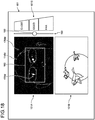
- FIG. 18 is a view illustrating an example of the display device 101 according to the present embodiment.
- the display controller 208 forms, on the display screen 101S of the display device 101, a first display area 101A for displaying the composite image 176M in which the eyeglasses reflection image 172M and the contour image 174M are combined, and a second display area 101B for displaying animations.
- the display controller 208 causes the display device 101 to display the eyeglasses reflection image 172M with the luminance higher than that of the contour image 174M.
- the display controller 208 causes the display device 101 to display the eyeglasses reflection image 172M with the luminance equal to or higher than the second threshold value, and causes the display device 101 to display the contour image 174M with the luminance lower than the first threshold value.
- the display controller 208 causes the display device 101 to display the contour image 174M and the eyeglasses reflection image 172M in different colors.
- the display controller 208 displays the contour image 174M in orange color, and displays the eyeglasses reflection image 172M in yellow color.
- the display controller 208 may cause the display device 101 to display the contour image 174M and the eyeglasses reflection image 172M with different lightness or different saturation.
- the eyeglasses reflection image 172M may be displayed on the display device 101 with lightness or saturation higher than that of the contour image 174M.
- the computer system 20 performs real-time image processing on the image data of the face of the subject obtained by the stereo camera device 102, and displays it in the first display area 101A of the display device 101. That is, a moving image of the composite image 176M is displayed on the display device 101.
- the subject or the measurer can adjust the position or the orientation of the face of the subject or can adjust the position or the orientation of the eyeglasses 170 such that the reflection image 172 of the light source 103 and the eye of the subject do not overlap in the visual field area of the stereo camera device 102 while viewing the composite image 176M displayed on the display device 101.
- the subject or the measurer can adjust the position or the orientation of the face of the subject or can adjust the position or the orientation of the eyeglasses 170 without a sense of discomfort or aversion.
- the display controller 208 causes the display screen 101S of the display device 101 to display a guide line 180 with a fixed dimension and position on the display screen 101S.
- the guide line 180 forms a rectangular shape.
- the guide line 180 is displayed to overlap the composite image 176M in the first display area 101A.
- the subject or the measurer can adjust the position of the face of the subject such that the eyes of the subject are placed inside the rectangular guide line 180 while viewing the composite image 176M.
- animations are displayed at an infant medical examination, for example.
- detection of a line of sight of an infant is performed in a state where the infant is sitting on parent's knees sitting on a chair.
- the relative position between the line-of-sight detection device 100 and the face of the infant is adjusted by the parent adjusting the position or the orientation of the face of the infant or by the measurer adjusting the position or the orientation of the line-of-sight detection device 100.
- animations for attracting the infant's attention are displayed in the second display area 101B to make the infant gaze at the display device 100.
- the display data displayed in the second display area 102B may be a moving image or a still image. Any display data that can attract the infant's attention may be used.
- the distance data acquisition unit 218 obtains distance data between the display screen 101S of the display device 101 and the eye or the face of the subject.
- the distance data acquisition unit 218 detects the pupil 112 based on the image data of the eyeball 111 of the subject obtained by the stereo camera device 102, and calculates the position of the pupil center 112C in the global coordinate system. By calculating the position of the pupil center 112C in the global coordinate system, the distance data acquisition unit 218 can calculate the distance between the center of the display screen 101S of the display device 101 and the eye of the subject.
- the display controller 208 causes the display device 101 to display the distance data obtained by the distance data acquisition unit 218.
- image data of a scale 190 indicating the distance between the display screen 101S of the display device 101 and the eye of the subject is displayed on the display device 101.
- character data of "close”, “good”, and “far” are displayed on the display device 101.
- the display controller 208 moves an indicator 192 along the scale 190 based on the distance data obtained by the distance data acquisition unit 218.
- the display controller 208 moves the indicator 192 to "good".
- the display controller 208 moves the indicator 192 to "close”.
- the display controller 208 moves the indicator 192 to "far”.
- the face of the subject is preferably located at a focal position of the optical system of the stereo camera device 102.
- the proper value of the distance between the display screen 101S of the display device 101 and the eye of the subject is a distance at which the eye or the face of the subject is located at the focal position of the optical system of the stereo camera device 102.
- the subject or the measurer can adjust the position of the face of the subject such that the indicator 192 is placed at the position of "good” while viewing the indicator 192.
- step S200 the calibration process, which includes the processing for calculating the positional data of the corneal curvature center 110 and the processing for calculating the distance data between the pupil center 112C and the corneal curvature center 110, is performed (step S200).
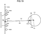
- FIG. 19 is a schematic diagram for illustrating an example of the calibration processing according to the present embodiment.
- the calibration processing includes calculation of the positional data of the corneal curvature center 110, and calculation of a distance 126 between the pupil center 112C and the corneal curvature center 110.
- a target position 130 for making the subject gaze is set.
- the target position 130 is defined in the global coordinate system.
- the target position 130 is set at a central position of the display screen 101S of the display device 101, for example. Note that the target position 130 may be set at the end position of the display screen 101S.
- the display controller 208 displays a target image at the set target position 130. Accordingly, the subject can easily gaze at the target position 130.
- a straight line 131 is a straight line connecting the virtual light source 103V and the corneal reflection center 113C.
- a straight line 132 is a straight line connecting the target position 130 and the pupil center 112C.
- the corneal curvature center 110 is an intersection point of the straight line 131 and the straight line 132.
- the curvature center calculation unit 214 can calculate the positional data of the corneal curvature center 110 based on the positional data of the virtual light source 103V, the positional data of the target position 130, the positional data of the pupil center 112C, and the positional data of the corneal reflection center 113C.
- FIG. 20 is a flowchart illustrating an exemplary calibration process (step S200) according to the present embodiment.
- the output controller 222 causes the display screen 101S of the display device 101 to display the target image (step S201).
- the subject can gaze at the target position 130 by gazing at the target image.
- the light source controller 210 controls the light source drive unit 406 to emit the detection light from one of the first light source 103A and the second light source 103B (step S202).
- the stereo camera device 102 takes an image of the eye of the subject with the camera having a longer distance from the light source that has emitted the detection light among the first camera 102A and the second camera 102B (step S203).
- the light source controller 210 controls the light source drive unit 406 to emit the detection light from the other one of the first light source 103A and the second light source 103B (step S204).
- the stereo camera device 102 takes an image of the eye of the subject with the camera having a longer distance from the light source that has emitted the detection light among the first camera 102A and the second camera 102B (step S205).
- the stereo camera device 102 detects the pupil 112 as a dark portion, and the stereo camera device 102 detects the corneal reflection image 113 as a bright portion. That is, the image of the pupil 112 obtained by the stereo camera device 102 has low luminance, and the image of the corneal reflection image 113 has high luminance.
- the position detection unit 212 can detect the positional data of the pupil 112 and the positional data of the corneal reflection image 113 based on the luminance of the obtained images. Further, the position detection unit 212 calculates the positional data of the pupil center 112C based on the image data of the pupil 112. Furthermore, the position detection unit 212 calculates the positional data of the corneal reflection center 113C based on the image data of the corneal reflection image 113 (step S206).
- the positional data detected by the stereo camera device 102 is positional data defined in the local coordinate system.
- the position detection unit 212 performs, using a transformation parameter stored in the storage 220, coordinate transformation on the positional data of the pupil center 112C and the positional data of the corneal reflection center 113C detected by the stereo camera device 102, and calculates the positional data of the pupil center 112C and the positional data of the corneal reflection center 113C defined in the global coordinate system (step S207).
- the curvature center calculation unit 214 obtains the straight line 131 connecting the corneal reflection center 113C and the virtual light source 103V defined in the global coordinate system (step S208).
- the curvature center calculation unit 214 calculates the straight line 132 connecting the target position 130 and the pupil center 112C defined on the display screen 101S of the display device 101 (step S209).
- the curvature center calculation unit 214 obtains an intersection point of the straight line 131 calculated in step S208 and the straight line 132 calculated in step S209, and sets the intersection point as the corneal curvature center 110 (step S210).
- the curvature center calculation unit 214 calculates the distance 126 between the pupil center 112C and the corneal curvature center 110, and stores it in the storage 220 (step S211). The stored distance is used to calculate the corneal curvature center 110 in the line-of-sight detection in step S300.
- the line-of-sight detection process is performed after the calibration process.
- the line-of-sight detection unit 216 calculates the line-of-sight vector and the positional data of the gaze point of the subject based on the image data of the eyeball 111.
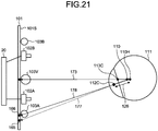
- FIG. 21 is a schematic diagram for illustrating exemplary line-of-sight detection processing according to the present embodiment.
- the line-of-sight detection process includes correction of the position of the corneal curvature center 110 using the distance 126 between the pupil center 112C and the corneal curvature center 110 obtained in the calibration process (step S200), and calculation of the gaze point using the positional data of the corrected corneal curvature center 110.
- a gaze point 165 indicates a gaze point obtained from the corneal curvature center calculated using a general curvature radius value.
- a gaze point 166 indicates a gaze point obtained from the corneal curvature center calculated using the distance 126 obtained in the calibration process.
- the pupil center 112C indicates the pupil center calculated in the calibration process
- the corneal reflection center 113C indicates the corneal reflection center calculated in the calibration process.
- a straight line 173 is a straight line connecting the virtual light source 103V and the corneal reflection center 113C.
- the corneal curvature center 110 is the position of the corneal curvature center calculated from a general curvature radius value.
- the distance 126 is a distance between the pupil center 112C calculated in the calibration process and the corneal curvature center 110.
- a corneal curvature center 110H indicates a position of the corrected corneal curvature center after the corneal curvature center 110 is corrected using the distance 126.
- the corneal curvature center 110H is obtained from the fact that the corneal curvature center 110 exists on the straight line 173 and the distance between the pupil center 112C and the corneal curvature center 110 is the distance 126.
- a line of sight 177 calculated in the case where a general curvature radius value is used is corrected to a line of sight 178.
- the gaze point on the display screen 101S of the display device 101 is corrected from the gaze point 165 to the gaze point 166.
- FIG. 22 is a flowchart illustrating an exemplary line-of-sight detection process (step S300) according to the present embodiment. Note that the processing from step S301 to step S307 illustrated in FIG. 22 is similar to the processing from step S202 to step S208 illustrated in FIG. 20 , and the descriptions thereof will be omitted.
- the curvature center calculation unit 214 calculates a position on the straight line 173 calculated in step S307 at which the distance from the pupil center 112C is equal to the distance 126 obtained in the calibration process as the corneal curvature center 110H (step S308).
- the line-of-sight detection unit 216 obtains a line-of-sight vector connecting the pupil center 112C and the corneal curvature center 110H (step S309).
- the line-of-sight vector indicates the line-of-sight direction along which the subject is viewing.
- the line-of-sight detection unit 216 calculates positional data of the intersection point of the line-of-sight vector and the display screen 101S of the display device 101 (step S310).
- the positional data of the intersection point of the line-of-sight vector and the display screen 101S of the display device 101 is the positional data of the gaze point of the subject on the display screen 101S defined in the global coordinate system.
- the line-of-sight detection unit 216 converts the positional data of the gaze point defined in the global coordinate system into the positional data on the display screen 101S of the display device 101 defined in a two-dimensional coordinate system (step S311). As a result, the positional data of the gaze point on the display screen 101S of the display device 101 viewed by the subject is calculated.
- the image data of the face of the subject obtained by the image data acquisition unit 202 is subject to the image processing in the image processing unit 206.
- the image processing unit 206 extracts, from the obtained image data, the contour image (feature image) 174M of the face and the eyeglasses reflection image 172M, and generates the composite image 176M.
- the composite image 176M generated by the image processing unit 206 is displayed on the display device 101.
- the subject or the measurer can adjust the position or the orientation of the face of the subject or can adjust the position or the orientation of the eyeglasses 170 worn on the face of the subject such that the reflection image 172 of the light source 103 and the eye of the subject do not overlap in the visual field area of the stereo camera device 102 while viewing the composite image 176M displayed on the display device 101. Therefore, in the line-of-sight detection process (step S300) performed after the positioning support process (step S100), the line-of-sight detection is performed in the state where the reflection image 172 of the light source 103 and the eye of the subject do not overlap in the visual field area of the stereo camera device 102.
- the pupil 112 and the corneal reflection image 113 are detected excellently with the influence of the reflection image 172 being sufficiently suppressed. Therefore, a decrease in detection accuracy of the line of sight of the subject wearing the eyeglasses 170 is suppressed.
- the raw data as illustrated in FIG. 12 is not displayed on the display device 101, but the composite image 176M as illustrated in FIGS. 17 and 18 is displayed on the display device 101.
- the detection light emitted onto the subject is infrared light.
- the raw data of the face of the subject at the time when the infrared light is emitted thereto has a higher possibility of giving a sense of discomfort or aversion to the subject or the measurer compared with the raw data of the face of the subject at the time when visible light is emitted thereto.
- the pupil is displayed in white, a blood vessel is displayed in a projected manner, or a beard is displayed in black excessively, whereby it is highly likely to give a sense of discomfort or aversion to the subject.
- the raw data of the face of the subject is subject to the image processing to generate the composite image 176M, and the generated composite image 176M is displayed on the display device 101. Accordingly, the subject or the measurer can adjust, while viewing the composite image 176M displayed on the display device 101, the position or the orientation of the face of the subject or the position or the orientation of the eyeglasses 170 without a sense of discomfort or aversion.
- the line-of-sight detection device 100 when used in the infant medical examination, giving a sense of discomfort or aversion to the parent in addition to the subject and the measurer is suppressed.
- the eyeglasses reflection image 172M is generated from the raw data by the image processing including binarization.
- the eyeglasses reflection image 172M being generated, a reflection state of the infrared light on the eyeglasses 170 is clearly grasped. Accordingly, the subject or the measurer can adjust the position or the orientation of the face of the subject or can adjust the position or the orientation of the eyeglasses 170 worn on the subject such that the reflection image 172 of the light source 103 and the eye of the subject do not overlap in the visual field area of the stereo camera device 102.
- the contour image 174M is generated from the raw data by the image processing including binarization and edge detection.
- the contour image 174M includes at least one of the contour image of the face of the subject, the contour image of the eyelid of the subject, the contour image of the pupil 112 of the subject, the contour image of the naris of the subject, the contour image of the mouth of the subject, and the contour image of the eyeglasses 170 worn on the face of the subject.
- Those contour images 174M are images from which the subject or the measurer can recognize or estimate the position of the eye of the subject when the subject or the measurer views the contour image 174M.
- the subject or the measurer can recognize or estimate the approximate position of the eye of the subject based on the contour image of the face.
- the subject or the measurer can recognize or estimate the approximate position of the eye of the subject based on the contour image of the naris or the contour image of the eyeglasses 170.
- the subject or the measurer can recognize the position of the eye of the subject.
- the subject or the measurer can recognize the relative position of the eye and the reflection image 172 based on the contour image 174M and the eyeglasses reflection image 172M displayed on the display device 101, and can adjust the position or the orientation of the face of the subject or can adjust the position or the orientation of the eyeglasses 170 worn on the subject such that the reflection image 172 of the light source 103 and the eye of the subject do not overlap in the visual field area of the stereo camera device 102.
- the display controller 208 causes the display device 101 to display the contour image 174M and the eyeglasses reflection image 172M in different display forms within the composite image 176M.
- the display form includes at least one of luminance, color, lightness, and saturation. Accordingly, the subject or the measurer can sufficiently distinguish the contour image 174M and the eyeglasses reflection image 172M.
- the display controller 208 causes the display device 101 to display the eyeglasses reflection image 172M with the luminance higher than that of the contour image 174M. Accordingly, the subject or the measurer can promptly recognize the eyeglasses reflection image 172M.
- the first threshold value and the second threshold value higher than the first threshold value are predetermined with regard to the luminance
- the image processing unit 206 generates the eyeglasses reflection image 172M having the luminance equal to or higher than the second threshold value and the contour image 174M having the luminance lower than the first threshold value.
- the display controller 208 causes the display device 101 to display the eyeglasses reflection image 172M with the luminance equal to or higher than the second threshold value, and causes the display device 101 to display the contour image 174M with the luminance lower than the first threshold value.
- the luminance of the contour image 174M is adjusted to 50% in a case where the luminance of the eyeglasses reflection image 172M is taken as 100%.
- the subject or the measurer can therefore sufficiently distinguish the contour image 174M and the eyeglasses reflection image 172M. Therefore, the subject or the measurer can smoothly perform adjustment such that, while viewing the composite image 176M displayed on the display device 101, the reflection image 172 of the light source 103 and the eye of the subject do not overlap in the visual field area of the stereo camera device 102.
- the distance data between the display screen 101S of the display device 101 and the face of the subject is displayed on the display device 101.
- the scale 190 and the indicator 192 are displayed on the display device 101 as the distance data.
- the distance data displayed on the display device 101 supports the subject or the measurer such that, in the line-of-sight detection process, the face of the subject is placed at the optimum position in the Z-axis direction. Accordingly, the subject or the measurer can place the face of the subject at the optimum distance relative to the display device 101 and the stereo camera device 102 while viewing the indicator 192 of the display device 101.
- the focal position of the optical system of the stereo camera device 102 is fixed, it becomes difficult to accurately detect the pupil 112 and the corneal reflection image 113 in the line-of-sight detection process when the distance between the subject and the display device 101/the stereo camera device 102 is too short.
- the image of the eye of the subject obtained by the stereo camera device 102 becomes small, whereby it becomes difficult to accurately detect the pupil 112 and the corneal reflection image 113 in the line-of-sight detection process.
- the display device 101 displays the distance data
- the subject or the measurer can place, while viewing the distance data displayed on the display device 101, the face of the subject at the optimum position in the Z-axis direction.
- the display controller 208 causes the display screen 101S of the display device 101 to display the guide line 180 with the fixed dimension and position on the display screen 101S.
- the guide line 180 displayed on the display device 101 supports the subject such that, in the line-of-sight detection process, the face of the subject is placed at the optimum position in the X-axis direction and the Y-axis direction.
- the subject or the measurer can place the face of the subject at the optimum position in the line-of-sight detection process based on the guide line 180.
- the first threshold value and the second threshold value higher than the first threshold value are predetermined, the luminance of the eyeglasses reflection image 172M is equal to or higher than the second threshold value, and the luminance of the contour image 174M is lower than the first threshold value.
- One threshold value may be predetermined for the luminance, the luminance of the eyeglasses reflection image 172M may be equal to or higher than the threshold value, and the luminance of the contour image 174M may be lower than the threshold value.
- an exemplary case where an amount of light of detection light emitted from a light source 103 is adjusted, and a contour image 174M and an eyeglasses reflection image 172M are generated based on image data obtained by a stereo camera device 102 at the time when the detection light with the adjusted amount of light is emitted onto a face of a subject will be described.
- an image processing unit 208 generates the contour image 174M and the eyeglasses reflection image 172M based on the image data of the face of the subject obtained by the stereo camera device 102 at the time when the light source 103 emits the detection light of a first amount of light and the image data of the face of the subject obtained by the stereo camera device 102 at the time when the light source 103 emits the detection light of a second amount of light larger than the first amount of light.
- a first light source 103A emits the detection light of the first amount of light
- a second light source 103B emits the detection light of the second amount of light larger than the first amount of light.
- the first light source 103A and the second light source 103B alternately emit the detection light.
- a second camera 102B of the stereo camera device 102 obtains the image data of the face of the subject at the time when the first light source 103A emits the detection light
- a first camera 102A obtains the image data of the face of the subject at the time when the second light source 103B emits the detection light.
- the amount of light of the detection light emitted from the light source 103 includes total luminous flux [lm] or luminosity [cd] indicating the total amount of light emitted from the light source 103.
- illuminance of the detection light emitted onto the face of the subject increases.
- the amount of light is small, the illuminance of the detection light emitted onto the face of the subject decreases.
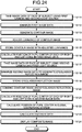
- FIG. 23 is a timing chart illustrating an operation timing of the first camera 102A, the second camera 102B, the first light source 103A, and the second light source 103B in the positioning support process according to the present embodiment.
- the first light source 103A and the second light source 103B alternately emit the detection light.
- the first camera 102A obtains the image data of the face of the subject in synchronization with the emission of the detection light from the second light source 103B.
- the second camera 102B obtains the image data of the face of the subject in synchronization with the emission of the detection light from the first light source 103A.
- the amount of light of the detection light emitted from the second light source 103B at the time when the first camera 102A obtains the image data is larger than the amount of light of the detection light emitted from the first light source 103A at the time when the second camera 102B obtains the image data.
- the first camera 102A when the first camera 102A operates, in other words, when the shutter of the first camera 102A opens, light enters the imaging element of the first camera 102A.
- the light entering the imaging element is converted into an electric signal.
- the electric signal is converted into a universal serial bus (USB) signal, and then transferred to a computer system 20 to activate the second light source 103B. That is, at the timing when the shutter of the first camera 102A opens, the detection light is emitted from the second light source 103B corresponding to the first camera 102A.
- USB universal serial bus
- the detection light in order to detect a dark pupil, is emitted from, among the first light source 103A and the second light source 103B, the second light source 103B disposed at a position away from the first camera 102A when the first camera 102A operates, and the detection light is emitted from, among the first light source 103A and the second light source 103B, the first light source 103A disposed at a position away from the second camera 102B when the second camera 102B operates.
- the detection light is emitted from, among the first light source 103A and the second light source 103B, the first light source 103A disposed at a position close to the first camera 102A when the first camera 102A operates, and the detection light is emitted from, among the first light source 103A and the second light source 103B, the second light source 103B disposed at a position close to the second camera 102B when the second camera 102B operates.
- time required for the second camera 102B and the first light source 103A to operate after the first camera 102A and the second light source 103B operate is short, and time required for the first camera 102A and the second light source 103B to operate after the second camera 102B and the first light source 103A operate is long. Since the time required for the second camera 102B and the first light source 103A to operate after the first camera 102A and the second light source 103B operate is short, right and left stereo images can be obtained at approximately the same timing.
- the contour image 174M is generated based on the image data obtained by the first camera 101A, and the eyeglasses reflection image 172M is generated based on the image data obtained by the second camera 101B.
- the contour image 174M is generated based on the image data of the face of the subject irradiated with the detection light of a large amount of light emitted from the second light source 103B
- the eyeglasses reflection image 172M is generated based on the image data of the face of the subject irradiated with the detection light of a small amount of light emitted from the first light source 103A.
- the face of the subject is illuminated with the detection light of a large amount of light. Therefore, when the image data obtained by the first camera 102A is binarized based on a predetermined threshold value, for example, as illustrated in FIG. 13 , most of a plurality of pixels of the binarized image data is converted into white color. That is, not only eyeglasses 170 but also the entire face of the subject is converted into white color. Edge detection is performed on the binarized image data, thereby generating the contour image 174M.
- the second camera 102B obtains the image data of the face of the subject
- the face of the subject is illuminated with the detection light of a small amount of light. Therefore, when the image data obtained by the second camera 102B is binarized based on the predetermined threshold value, for example, as illustrated in FIG. 16 , among a plurality of pixels of the binarized image data, only pixels corresponding to a reflection image 172 are converted into white color, and pixels corresponding to the face of the subject are converted into black color. That is, the image data of the face of the subject illuminated with the detection light of a small amount of light is binarized, thereby generating the eyeglasses reflection image 172M.
- FIG. 24 is a flowchart illustrating an exemplary positioning support process according to the present embodiment.
- the light source controller 210 causes the second light source 103B to emit the detection light of a large amount of light.
- the image data of the face of the subject illuminated with the detection light of the large amount of light is obtained by the first camera 102A (step S111).
- the image data acquisition unit 202 acquires the image data from the first camera 102A.
- the image processing unit 206 binarizes first image data, which is the image data obtained by the first camera 102A, based on the predetermined threshold value (step S112). As a result, the image data as illustrated in FIG. 13 is generated.
- the image processing unit 206 performs the edge detection on the binarized first image data. As a result, the contour image 174M as illustrated in FIG. 14 is generated (step S113).
- the image processing unit 206 adjusts the luminance of the contour image 174M (step S114).
- the image processing unit 206 reduces the luminance of the contour image 174M.
- the contour image 174M as illustrated in FIG. 15 is generated.
- the contour image 174M having been subject to the luminance adjustment is stored in the storage 220 (step S115) .
- the position detection unit 212 calculates the position of the pupil center 112C of each of the right and left eyes in the first image data (step S116).
- the light source controller 210 causes the first light source 103A to emit the detection light of a small amount of light.
- the image data of the face of the subject illuminated with the detection light of the small amount of light is obtained by the second camera 102B (step S117).
- the image data acquisition unit 202 acquires the image data from the second camera 102B.
- the image processing unit 206 binarizes second image data, which is the image data obtained by the second camera 102B, based on the predetermined threshold value (step S118). As a result, the image data as illustrated in FIG. 16 is generated. That is, the second image data is binarized, thereby generating the eyeglasses reflection image 172M.
- the same value is used as the threshold value for binarizing the second image data used in step S118 and the threshold value for binarizing the first image data used in the step S112.
- the generated eyeglasses reflection image 172M is stored in the storage 220 (step S119).
- the image processing unit 206 combines the contour image 174M and the eyeglasses reflection image 172M stored in the storage 220 (step S120). As a result, the composite image 176M as illustrated in FIG. 17 is generated.
- the position detection unit 212 calculates the position of the pupil center 112C of each of the right and left eyes in the second image data (step S121).
- the curvature center calculation unit 214 calculates the position of the pupil center 112C in the global coordinate system based on at least one of the positional data of the pupil center 112C calculated based on the first image data in step S116 and the positional data of the pupil center 112C calculated based on the second image data in step S121 (step S122).
- the distance data acquisition unit 218 calculates distance data between the display screen 101S of the display device 101 and the face of the subject based on the positional data of the pupil center 112C calculated in step S122 (step S123).
- the display controller 208 causes the display device 101 to display the composite image 176M generated in step S120 (step S124). Further, the display controller 208 causes the display device 101 to display the distance data calculated in step S123. In a similar manner to the above-described embodiment, the display controller 208 causes the display device 101 to display the scale 190 and the indicator 192 as the distance data.
- the distance data between the display screen 101S of the display device 101 and the face of the subject may be calculated based on, among the positional data of the pupil center 112C of the right and left eyes, the positional data of the pupil center 112C of either one of the eyes.
- the distance data between the display screen 101S of the display device 101 and the face of the subject may be calculated based on an average value of the positional data of the pupil center 112C of the right and left eyes.
- the amount of light of the detection light emitted from the light source 103 is changed in the positioning support process.
- only one threshold value suffices as a threshold value for the luminance used in the image processing.
- a computer program 20C for controlling a line-of-sight detection device 100 is therefore simplified. For example, by merely changing the amount of light of the light source 103 in the positioning process, no big difference between contents of the computer program 20C used in the positioning support process and contents of the computer program 20C used in the line-of-sight detection process is needed.
- the contour image 174M and the eyeglasses reflection image 172M are obtained by controlling the amount of light of the detection light emitted from the light source 103. That is, when the image data of the face of the subject is obtained by the first camera 102A, the face of the subject is illuminated with the detection light of a large amount of light to generate the contour image 174M based on the image data of the face of the subject illuminated with the detection light of the large amount of light, and when the image data of the face of the subject is obtained by the second camera 102B, the face of the subject is illuminated with the detection light of a small amount of light to generate the eyeglasses reflection image 172M based on the image data of the face of the subject illuminated with the detection light of the small amount of light.
- the image processing unit 206 may generate the contour image 174M and the eyeglasses reflection image 172M based on the image data of the subject's face, obtained by the first and second cameras 102A and 102B and acquired by the image data acquisition unit 202, of a first exposure amount and the image data of the subject's face of a second exposure amount smaller than the first exposure amount.
- the exposure amount of the image data of the subject's face obtained by the first and second cameras 102A and 102B can be adjusted based on at least one of light emission intensity of the light source 103, light emission time of the light source 103, and an exposure value of the first and second cameras 102A and 102B.
- the light source controller 210 can control the light emission intensity of the first and second light sources 103A and 103B and the light emission time of the first and second light sources 103A and 103B.
- a camera controller 211 can control the exposure value in the imaging element by controlling at least one of a shutter speed and an aperture value of the optical system of the first and second cameras 102A and 102B.
- the light source controller 210 may increase the light emission intensity of the second light source 103B, the light source controller 210 may increase the light emission time of the second light source 103B, the camera controller 211 may reduce the shutter speed of the first camera 102A, and the camera controller 211 may reduce the aperture value of the optical system of the first camera 102A to increase the exposure amount of the image data of the subject's face obtained by the first camera 102A, and thus the image processing unit 206 may generate the contour image 174M based on the image data of the face of the subject having a large exposure amount.
- the light source controller 210 may reduce the light emission intensity of the first light source 103A, the light source controller 210 may reduce the light emission time of the first light source 103A, the camera controller 211 may increase the shutter speed of the second camera 102B, and the camera controller 211 may increase the aperture value of the optical system of the second camera 102B to reduce the exposure amount of the image data of the subject's face obtained by the second camera 102B, and thus the image processing unit 206 may generate the eyeglasses reflection image 172M based on the image data of the face of the subject having a small exposure amount.
- the contour image 174M is generated from the first image data obtained by the first camera 102A
- the eyeglasses reflection image 172M is generated from the second image data obtained by the second camera 102B.
- the contour image 174M and the eyeglasses reflection image 172M are generated from separate image data
- the composite image 176M having sufficient accuracy is generated from the viewpoint of supporting positioning.
- a lens of the eyeglasses 170 may be a prescription lens having eyesight adjustment function, or may be a lens having no eyesight adjustment function. Besides, the eyeglasses 170 may or may not have a light shielding function. In the present embodiment, the eyeglasses 170 include sunglasses.
- the eyeglasses 170 may not be worn on the face of the subject.
- the eyeglasses 170 is a concept including an optical member having a light transmission function disposed between the line-of-sight detection device 100 and the eye of the subject.
- the eyeglasses reflection image 172M has the luminance higher than that of the contour image 174M.
- the luminance of the eyeglasses reflection image 172M may be the same as the luminance of the contour image 174M, or may be lower than the luminance of the contour image 174M.
- the eyeglasses reflection image 172M and the contour image 174M are preferably displayed in different colors.
- the feature image of the face of the subject is the contour image generated by the edge detection.
- the feature image only needs to be an image from which the position of the eye of the subject can be recognized or estimated when the subject or the measurer views the feature image, and may not be the contour image obtained by the edge detection.
- the present embodiments are suitable for performing detection of a line of sight of a subject wearing eyeglasses.
Landscapes
- Engineering & Computer Science (AREA)
- Health & Medical Sciences (AREA)
- Physics & Mathematics (AREA)
- Life Sciences & Earth Sciences (AREA)
- Theoretical Computer Science (AREA)
- General Physics & Mathematics (AREA)
- General Health & Medical Sciences (AREA)
- Multimedia (AREA)
- Human Computer Interaction (AREA)
- Ophthalmology & Optometry (AREA)
- Biomedical Technology (AREA)
- Animal Behavior & Ethology (AREA)
- Veterinary Medicine (AREA)
- Biophysics (AREA)
- Public Health (AREA)
- Heart & Thoracic Surgery (AREA)
- Medical Informatics (AREA)
- Molecular Biology (AREA)
- Surgery (AREA)
- Oral & Maxillofacial Surgery (AREA)
- Signal Processing (AREA)
- Computer Vision & Pattern Recognition (AREA)
- Computer Hardware Design (AREA)
- Eye Examination Apparatus (AREA)
- Image Analysis (AREA)
- Image Input (AREA)
- Image Processing (AREA)
- Studio Devices (AREA)
Abstract
Description
- The present invention relates to a line-of-sight detection device, a method for detecting a line of sight, and a computer program.
- As a technique for detecting a line of sight, a corneal reflection method has been known. The corneal reflection method is a method for detecting a line of sight of a subject in which the subject is irradiated with infrared light emitted from a light source, an eye of the subject irradiated with the infrared light is captured by a camera, and a position of a pupil with respect to a corneal reflection image, which is a reflection image of a light source on a corneal surface, is detected.
- Patent Literature 1: Japanese Laid-open Patent Publication No.
JP 2010-244156 A - In a case where the subject is wearing eyeglasses, there is a possibility that the infrared light emitted to the subject is reflected by the eyeglasses. When the infrared light is reflected by the eyeglasses, the detection accuracy of the line of sight may be lowered.
- For example, in a case where the reflection image of the light source on the eyeglasses and the eye of the subject overlap in the visual field area of the camera, it becomes difficult to detect the corneal reflection image and the pupil. When the corneal reflection image and the pupil are not detected excellently, the detection accuracy of the line of sight of the subject is lowered.
- An object of the present embodiment is to provide a line-of-sight detection device, a method for detecting a line of sight, and a computer program capable of suppressing deterioration of detection accuracy of a line of sight of a subject wearing eyeglasses.
- According to one aspect, there is provided a line-of-sight detection device, comprising: an image data acquisition unit that acquires image data of a face of a subject irradiated with detection light emitted from a light source; a line-of-sight detection unit that detects a line of sight of the subject based on the image data; an image processing unit that performs image processing on the image data to generate a feature image of the face and an eyeglasses reflection image indicating a reflection image of the light source on eyeglasses worn on the face; and a display controller that causes a display device to display the feature image and the eyeglasses reflection image in a different display form in a composite image in which the feature image and the eyeglasses reflection image are combined.
- According to the present embodiment, there are provided a line-of-sight detection device, a method for detecting a line of sight, and a computer program capable of suppressing deterioration of detection accuracy of a line of sight of a subject wearing eyeglasses.
-
-
FIG. 1 is a perspective view schematically illustrating an exemplary line-of-sight detection device according to a first embodiment. -
FIG. 2 is a diagram schematically illustrating a positional relationship among a display device, a stereo camera device, a light source, and an eyeball of a subject according to the first embodiment. -
FIG. 3 is a diagram illustrating an exemplary hardware configuration of the line-of-sight detection device according to the first embodiment. -
FIG. 4 is a functional block diagram illustrating an example of the line-of-sight detection device according to the first embodiment. -
FIG. 5 is a schematic diagram for illustrating a method for calculating positional data of a corneal curvature center according to the first embodiment. -
FIG. 6 is another schematic diagram for illustrating the method for calculating the positional data of the corneal curvature center according to the first embodiment. -
FIG. 7 is a flowchart illustrating an example of a method for detecting a line of sight according to the first embodiment. -
FIG. 8 is a diagram schematically illustrating a relationship among a pupil of a subject wearing eyeglasses, a stereo camera device, and a light source. -
FIG. 9 is a schematic view illustrating a state in which at least a part of a reflection image of the light source on the eyeglasses overlaps the pupil of the subject in a visual field area of the stereo camera device. -
FIG. 10 is a diagram schematically illustrating the relationship among the pupil of the subject wearing the eyeglasses, the stereo camera device, and the light source. -
FIG. 11 is a flowchart illustrating an exemplary positioning support process according to the first embodiment. -
FIG. 12 is a view schematically illustrating exemplary image data obtained by an image data acquisition unit according to the first embodiment. -
FIG. 13 is a view schematically illustrating exemplary binarized image data according to the first embodiment. -
FIG. 14 is a view schematically illustrating an exemplary feature image of the face of the subject according to the first embodiment. -
FIG. 15 is a view schematically illustrating an exemplary feature image with reduced luminance according to the first embodiment. -
FIG. 16 is a view schematically illustrating an exemplary eyeglasses reflection image according to the first embodiment. -
FIG. 17 is a view schematically illustrating an exemplary composite image obtained by combining the feature image and the eyeglasses reflection image according to the first embodiment. -
FIG. 18 is a view illustrating an example of the display device according to the first embodiment. -
FIG. 19 is a schematic diagram for illustrating exemplary calibration processing according to the first embodiment. -
FIG. 20 is a flowchart illustrating the exemplary calibration process according to the first embodiment. -
FIG. 21 is a schematic diagram for illustrating exemplary line-of-sight detection processing according to the first embodiment. -
FIG. 22 is a flowchart illustrating the exemplary line-of-sight detection process according to the first embodiment. -
FIG. 23 is a timing chart illustrating an operation timing of a first camera, a second camera, a first light source, and a second light source in a positioning support process according to a second embodiment. -
FIG. 24 is a flowchart illustrating an example of the positioning support process according to the second embodiment. - Hereinafter, embodiments of the present invention will be described with reference to the accompanying drawings, but the present invention is not limited thereto. Constituent elements of the embodiments described below may be appropriately combined. In addition, some constituent elements may not be used.
- In the following descriptions, a positional relationship between respective parts will be described by setting a three-dimensional global coordinate system. A direction parallel to an X axis of a predetermined plane is defined as an X-axis direction, a direction parallel to a Y axis of the predetermined plane orthogonal to the X axis is defined as a Y-axis direction, and a direction parallel to a Z axis orthogonal to each of the X axis and the Y axis is defined as a Z-axis direction. The predetermined plane includes an XY plane.
- A first embodiment will be described.
FIG. 1 is a perspective view schematically illustrating an exemplary line-of-sight detection device 100 according to the present embodiment. The line-of-sight detection device 100 is used for, for example, a diagnostic support apparatus for supporting diagnosis of developmental disorder. - As illustrated in
FIG. 1 , the line-of-sight detection device 100 includes adisplay device 101, astereo camera device 102, and alight source 103. - The
display device 100 includes a flat panel display such as a liquid crystal display (LCD) and an organic electroluminescence display (OELD). - In the present embodiment, a
display screen 101S of thedisplay device 100 is substantially parallel to the XY plane. The X-axis direction is a horizontal direction of thedisplay screen 101S, the Y-axis direction is a vertical direction of thedisplay screen 101S, and the Z-axis direction is a depth direction orthogonal to thedisplay screen 101S. - The
stereo camera device 102 takes an image of a subject and obtains image data of the subject. Thestereo camera device 102 includes afirst camera 102A and asecond camera 102B, which are disposed at different positions. Thestereo camera device 102 is disposed below thedisplay screen 101S of thedisplay device 101. Thefirst camera 102A and thesecond camera 102B are disposed in the X-axis direction. Thefirst camera 102A is disposed in the -X direction with respect to thesecond camera 102B. Each of thefirst camera 102A and thesecond camera 102B includes an infrared camera, and has, for example, an optical system capable of transmitting near-infrared light with a wavelength of 850 nm and an imaging element capable of receiving the near-infrared light. - The
light source 103 emits detection light. Thelight source 103 includes afirst light source 103A and asecond light source 103B, which are disposed at different positions. Thelight source 103 is disposed below thedisplay screen 101S of thedisplay device 101. The firstlight source 103A and the secondlight source 103B are disposed in the X-axis direction. The firstlight source 103A is disposed in the -X direction with respect to thefirst camera 102A. The secondlight source 103B is disposed in the +X direction with respect to thesecond camera 102B. Each of the firstlight source 103A and the secondlight source 103B includes a light emitting diode (LED), and is capable of emitting near-infrared light with a wavelength of 850 nm, for example. Note that the firstlight source 103A and the secondlight source 103B may be disposed between thefirst camera 102A and thesecond camera 102B. -
FIG. 2 is a diagram schematically illustrating a positional relationship among thedisplay device 101, thestereo camera device 102, thelight source 103, and aneyeball 111 of the subject according to the present embodiment. - The
light source 103 emits infrared light as detection light to illuminate theeyeball 111 of the subject. Thestereo camera device 102 takes an image of theeyeball 111 with thesecond camera 102B when theeyeball 111 is irradiated with the detection light emitted from the firstlight source 103A, and takes an image of theeyeball 111 with thefirst camera 102A when theeyeball 111 is irradiated with the detection light emitted from the secondlight source 103B. - A frame synchronous signal is output from at least one of the
first camera 102A and thesecond camera 102B. The firstlight source 103A and the secondlight source 103B emit the detection light based on the frame synchronous signal. When theeyeball 111 is irradiated with the detection light emitted from the secondlight source 103B, thefirst camera 102A obtains image data of theeyeball 111. When theeyeball 111 is irradiated with the detection light emitted from the firstlight source 103A, thesecond camera 102B obtains image data of theeyeball 111. - When the
eyeball 111 is irradiated with the detection light, a part of the detection light is reflected by apupil 112. The light reflected by thepupil 112 enters thestereo camera device 102. Further, when theeyeball 111 is irradiated with the detection light, acorneal reflection image 113 is formed on theeyeball 111. Thecorneal reflection image 113 is a reflection image of thelight source 103 on a corneal surface. The light from thecorneal reflection image 113 enters thestereo camera device 102. - By appropriately setting relative positions of the
first camera 102A, thesecond camera 102B, the firstlight source 103A, and the secondlight source 103B, an intensity of the light entering thestereo camera device 102 from thepupil 112 decreases, and an intensity of the light entering thestereo camera device 102 from thecorneal reflection image 113 increases. That is, the image of thepupil 112 obtained by thestereo camera device 102 has low luminance, and the image of thecorneal reflection image 113 has high luminance. Thestereo camera device 102 can detect a position of thepupil 112 and a position of thecorneal reflection image 113 based on the luminance of the obtained images. -
FIG. 3 is a diagram illustrating an exemplary hardware configuration of the line-of-sight detection device 100 according to the present embodiment. As illustrated inFIG. 3 , the line-of-sight detection device 100 includes thedisplay device 101, thestereo camera device 102, thelight source 103, acomputer system 20, an input/output interface device 30, a drivingcircuit 40, anoutput device 50, aninput device 60, and avoice output device 70. Thecomputer system 20 includes anarithmetic processing unit 20A and astorage unit 20B. Acomputer program 20C is stored in thestorage unit 20B. - The
computer system 20, the drivingcircuit 40, theoutput device 50, theinput device 60, and thevoice output device 70 perform data communication via the input/output interface device 30. - The
arithmetic processing unit 20A includes a microprocessor such as a central processing unit (CPU). Thestorage unit 20B includes a nonvolatile memory such as a read-only memory (ROM), or a volatile memory such as a random access memory (RAM). Thearithmetic processing unit 20A executes arithmetic processing according to thecomputer program 20C stored in thestorage unit 20B. - The driving
circuit 40 generates a drive signal, and outputs it to thedisplay device 101, thestereo camera device 102, and thelight source 103. Further, the drivingcircuit 40 supplies the image data of theeyeball 111 obtained by thestereo camera device 102 to thecomputer system 20 via the input/output interface device 30. - The
output device 50 includes a display device such as a flat panel display. Note that theoutput device 50 may include a printer. Theinput device 60 generates input data by being operated. Theinput device 60 includes a keyboard or a mouse for a computer system. Note that theinput device 60 may include a touch sensor provided on the display screen of theoutput device 50 that is the display device. Thevoice output device 70 includes a speaker, and outputs, for example, voice for calling the subject's attention. - In the present embodiment, the
display device 101 and thecomputer system 20 are separate devices. Note that thedisplay device 101 and thecomputer system 20 may be integrated. For example, in a case where the line-of-sight detection device 100 includes a tablet personal computer system, thecomputer system 20, the input/output interface device 30, the drivingcircuit 40, and thedisplay device 101 may be mounted on the tablet personal computer. -
FIG. 4 is a functional block diagram illustrating an example of the line-of-sight detection device 100 according to the present embodiment. As illustrated inFIG. 4 , the input/output interface device 30 includes an input/output unit 302. The drivingcircuit 40 includes a displaydevice drive unit 402 that generates a drive signal for driving thedisplay device 101 and outputs it to thedisplay device 101, a first camera input/output unit 404A that generates a drive signal for driving thefirst camera 102A and outputs it to thefirst camera 102A, a second camera input/output unit 404B that generates a drive signal for driving thesecond camera 102B and outputs it to thesecond camera 102B, and a lightsource drive unit 406 that generates a drive signal for driving the firstlight source 103A and the secondlight source 103B and outputs it to the firstlight source 103A and the secondlight source 103B. Further, the first camera input/output unit 404A supplies the image data of theeyeball 111 obtained by thefirst camera 102A to thecomputer system 20 via the input/output unit 302. The second camera input/output unit 404B supplies the image data of theeyeball 111 obtained by thesecond camera 102B to thecomputer system 20 via the input/output unit 302. - The
computer system 20 controls the line-of-sight detection device 100. Thecomputer system 20 includes an imagedata acquisition unit 202, an inputdata acquisition unit 204, animage processing unit 206, adisplay controller 208, alight source controller 210, acamera controller 211, aposition detection unit 212, a curvaturecenter calculation unit 214, a line-of-sight detection unit 216, a distancedata acquisition unit 218, astorage 220, and anoutput controller 222. A function of thecomputer system 20 are performed by thearithmetic processing unit 20A, thestorage unit 20B, and thecomputer program 20C stored in thestorage unit 20B. - The image
data acquisition unit 202 acquires the image data of a face of the subject captured by thestereo camera device 102 including thefirst camera 102A and thesecond camera 102B from thestereo camera device 102 via the input/output unit 302. The image data is digital data. The image data of the face of the subject includes the image data of theeyeball 111. Thestereo camera device 102 takes the image of the face of the subject to be irradiated with the detection light emitted from thelight source 103. The imagedata acquisition unit 202 acquires the image data of the face of the subject to be irradiated with the detection light emitted from thelight source 103 from thestereo camera device 102 via the input/output unit 302. - The input
data acquisition unit 204 acquires the input data generated by theinput device 60 being operated from theinput device 60 via the input/output unit 302. - The
image processing unit 206 performs image processing on the image data acquired by the imagedata acquisition unit 202. Theimage processing unit 206 performs the image processing on the image data, and generates a feature image indicating an image of a feature portion within the face of the subject, and generates an eyeglasses reflection image indicating a reflection image of thelight source 103 on the eyeglasses worn on the face of the subject. - The
display controller 208 causes thedisplay device 101 to display a specific image. In the present embodiment, thedisplay controller 208 causes thedisplay device 101 to display a composite image in which the feature image and the eyeglasses reflection image generated by theimage processing unit 206 are combined. Thedisplay controller 208 causes thedisplay device 101 to display the feature image and the eyeglasses reflection image in a different display form in the composite image in which the feature image and the eyeglasses reflection image are combined. The display form on thedisplay device 101 includes at least one of luminance, color, lightness, and saturation of the image. In the present embodiment, thedisplay controller 208 causes thedisplay device 101 to display the eyeglasses reflection image in an emphasized manner compared with the feature image. For example, thedisplay controller 208 causes thedisplay device 101 to display the eyeglasses reflection image with luminance higher than that of the feature image in the composite image. Note that thedisplay controller 208 may cause thedisplay device 101 to display the eyeglasses reflection image with lightness higher than that of the feature image or with saturation higher than that of the feature image in the composite image. - The
light source controller 210 controls the lightsource drive unit 406 to control an operating state of the firstlight source 103A and the secondlight source 103B. Thelight source controller 210 controls the firstlight source 103A and the secondlight source 103B such that the firstlight source 103A and the secondlight source 103B emit the detection light at different timings. Further, thelight source controller 210 controls the amount of light of the detection light emitted from the firstlight source 103A and the amount of light of the detection light emitted from the secondlight source 103B. The control of the amount of light of the detection light emitted from the firstlight source 103A includes at least one of control of light emission intensity of the firstlight source 103A and control of light emission time of the firstlight source 103A. Likewise, the control of the amount of light of the detection light emitted from the secondlight source 103B includes at least one of control of light emission intensity of the secondlight source 103B and control of light emission time of the secondlight source 103B. In the present embodiment, thelight source controller 210 controls the firstlight source 103A and the secondlight source 103B such that the amount of light of the detection light emitted from the firstlight source 103A and the amount of light of the detection light emitted from the secondlight source 103B become the same amount. - The
camera controller 211 controls the first camera input/output unit 404A and the second camera input/output unit 404B to control an operating state of thestereo camera device 102 including thefirst camera 102A and thesecond camera 102B. Thecamera controller 211 controls an exposure value of the detection light in thefirst camera 102A and an exposure value of the detection light in thesecond camera 102B. Each of the exposure value of the detection light in the first andsecond cameras second cameras second cameras second cameras second cameras - The
position detection unit 212 detects positional data of a pupil center based on the image data of theeyeball 111 acquired by the imagedata acquisition unit 202. Further, theposition detection unit 212 detects positional data of a corneal reflection center based on the image data of theeyeball 111 acquired by the imagedata acquisition unit 202. The pupil center is a center of thepupil 112. The corneal reflection center is a center of thecorneal reflection image 113. Theposition detection unit 212 detects the positional data of the pupil center and the positional data of the corneal reflection center with respect to each of the right and lefteyeballs 111 of the subject. - The curvature
center calculation unit 214 calculates positional data of a corneal curvature center of theeyeball 111 based on the image data of theeyeball 111 acquired by the imagedata acquisition unit 202. - The line-of-
sight detection unit 216 detects a line of sight of the subject based on the image data of theeyeball 111 acquired by the imagedata acquisition unit 202. The line of sight of the subject includes a line-of-sight vector indicating a line-of-sight direction being observed by the subject. The line-of-sight detection unit 216 detects line-of-sight vectors of the right and lefteyeballs 111 of the subject based on the positional data of the pupil center and the positional data of the corneal curvature center obtained from the image data of theeyeball 111. - Further, the line-of-
sight detection unit 216 detects positional data of a gaze point of the subject based on the detected line-of-sight vector. In the present embodiment, the gaze point of the subject includes an intersection point of the line-of-sight vector of the subject and thedisplay screen 101S of thedisplay device 101. In the present embodiment, the positional data of the gaze point indicates positional data of the intersection point of the line-of-sight vector of the subject defined in the global coordinate system and thedisplay screen 101S of thedisplay device 101. - The distance
data acquisition unit 218 obtains distance data between thedisplay screen 101S of thedisplay device 101 and the face of the subject. The distancedata acquisition unit 218 detects distance data based on the positional data of the pupil center detected by theposition detection unit 212. The positional data of the pupil center in the global coordinate system is detected, whereby a distance between the center of thedisplay screen 101S of thedisplay device 101 and theeyeball 111 of the subject is calculated. The distancedata acquisition unit 218 obtains the distance between the center of thedisplay screen 101S of thedisplay device 101 and theeyeball 111 of the subject as the distance data between thedisplay screen 101S of thedisplay device 101 and the face of the subject. - The
storage 220 stores thecomputer program 20C and various data. - The
output controller 222 outputs data to at least one of thedisplay device 101, theoutput device 50, and thevoice output device 70. For example, theoutput controller 222 causes thedisplay device 101 or theoutput device 50 to display the positional data of the gaze point of each of the right and lefteyeballs 111 of the subject. - Next, a principle of line-of-sight detection according to the present embodiment will be described. In the following descriptions, the outline of processing performed by the curvature
center calculation unit 214 will be mainly described. The curvaturecenter calculation unit 214 calculates the positional data of the corneal curvature center of theeyeball 111 based on the image data of theeyeball 111. -
FIGS. 5 and6 are schematic diagrams for illustrating a method for calculating the positional data of thecorneal curvature center 110 according to the present embodiment.FIG. 5 illustrates an exemplary case where theeyeball 111 is illuminated by onelight source 103C.FIG. 6 illustrates an exemplary case where theeyeball 111 is illuminated by the firstlight source 103A and the secondlight source 103B. - First, the exemplary case illustrated in
FIG. 5 will be described. Thelight source 103C is disposed between thefirst camera 102A and thesecond camera 102B. Apupil center 112C is a center of thepupil 112. Acorneal reflection center 113C is a center of thecorneal reflection image 113. InFIG. 5 , thepupil center 112C indicates the pupil center at the time when theeyeball 111 is illuminated by onelight source 103C. Thecorneal reflection center 113C indicates the corneal reflection center at the time when theeyeball 111 is illuminated by onelight source 103C. - The
corneal reflection center 113C exists on a straight line connecting thelight source 103C and thecorneal curvature center 110. Thecorneal reflection center 113C is positioned at a middle point between the corneal surface and thecorneal curvature center 110. Acorneal curvature radius 109 is a distance between the corneal surface and thecorneal curvature center 110. - Positional data of the
corneal reflection center 113C is detected by thestereo camera device 102. Thecorneal curvature center 110 exists on a straight line connecting thelight source 103C and thecorneal reflection center 113C. The curvaturecenter calculation unit 214 calculates positional data at which a distance from thecorneal reflection center 113C on the straight line corresponds to a predetermined value as positional data of thecorneal curvature center 110. The predetermined value is a value determined in advance from a general curvature radius value of the cornea, which is stored in thestorage 220. - Next, the exemplary case illustrated in
FIG. 6 will be described. In the present embodiment, thefirst camera 102A and the secondlight source 103B, and thesecond camera 102B and the firstlight source 103A are symmetrically disposed with respect to a straight line passing through an intermediate position between thefirst camera 102A and thesecond camera 102B. It can be assumed that a virtuallight source 103V exists at the intermediate position between thefirst camera 102A and thesecond camera 102B. - A
corneal reflection center 121 indicates a corneal reflection center in the image of theeyeball 111 captured by thesecond camera 102B. Acorneal reflection center 122 indicates a corneal reflection center in the image of theeyeball 111 captured by thefirst camera 102A. Acorneal reflection center 124 indicates a corneal reflection center corresponding to the virtuallight source 103V. - Positional data of the
corneal reflection center 124 is calculated based on positional data of thecorneal reflection center 121 and positional data of thecorneal reflection center 122 obtained by thestereo camera device 102. Thestereo camera device 102 detects the positional data of thecorneal reflection center 121 and the positional data of thecorneal reflection center 122 in a local coordinate system defined by thestereo camera device 102. Camera calibration based on a stereo calibration method is performed on thestereo camera device 102 in advance, and a conversion parameter for converting the three-dimensional local coordinate system of thestereo camera device 102 into a three-dimensional global coordinate system is calculated. The conversion parameter is stored in thestorage 220. - The curvature
center calculation unit 214 converts, using the conversion parameter, the positional data of thecorneal reflection center 121 and the positional data of thecorneal reflection center 122 obtained by thestereo camera device 102 into positional data in the global coordinate system. The curvaturecenter calculation unit 214 calculates the positional data of thecorneal reflection center 124 in the global coordinate system based on the positional data of thecorneal reflection center 121 and the positional data of thecorneal reflection center 122 defined in the global coordinate system. - The
corneal curvature center 110 exists on astraight line 123 connecting the virtuallight source 103V and thecorneal reflection center 124. The curvaturecenter calculation unit 214 calculates positional data at which a distance from thecorneal reflection center 124 on thestraight line 123 corresponds to a predetermined value as positional data of thecorneal curvature center 110. The predetermined value is a value determined in advance from a general curvature radius value of the cornea, which is stored in thestorage 220. - As described with reference to
FIG. 6 , even in a case where there are two light sources, thecorneal curvature center 110 is calculated according to the method similar to the method of a case where there is one light source. - A
corneal curvature radius 109 is a distance between the corneal surface and thecorneal curvature center 110. Therefore, thecorneal curvature radius 109 is calculated by calculating the positional data of the corneal surface and the positional data of thecorneal curvature center 110. - In this manner, in the present embodiment, the positional data of the
corneal curvature center 110, the positional data of thecorneal reflection center 124, and the positional data of thepupil center 112C in the global coordinate system are calculated. - The line-of-
sight detection unit 216 is capable of detecting the line-of-sight vector of the subject based on the positional data of thepupil center 112C and the positional data of thecorneal curvature center 110. Further, the distancedata acquisition unit 218 is capable of obtaining the distance data between the display screen of thedisplay device 101 and the face of the subject including theeyeball 111 based on the positional data of thepupil center 112C. - Next, an example of a method for detecting a line of sight according to the present embodiment will be described.
FIG. 7 is a flowchart illustrating an example of a method for detecting a line of sight according to the present embodiment. In the present embodiment, a positioning support process for adjusting the line-of-sight detection device 100 and the subject to a proper relative position (step S100), a calibration process including processing for calculating the positional data of thecorneal curvature center 110 and processing for calculating the distance data between thepupil center 112C and the corneal curvature center 110 (step S200), and a line-of-sight detection process (step S300) are performed. - The positioning support process will be described. In a case where eyeglasses are worn on the face of the subject, there is a possibility that at least a part of the detection light emitted from the
light source 103 onto the face of the subject is reflected by the lens of the eyeglasses. -
FIG. 8 is a diagram schematically illustrating a relationship among thepupil 112 of thesubject wearing eyeglasses 170, thestereo camera device 102, and thelight source 103.FIG. 8 illustrates a state in which a position of areflection image 172 of thelight source 103 on theeyeglasses 170 and the position of thepupil 112 of the subject coincide with each other in the visual field area of thestereo camera device 102.FIG. 9 is a schematic view illustrating a state in which at least a part of thereflection image 172 of thelight source 103 on theeyeglasses 170 overlaps thepupil 112 of the subject in the visual field area of thestereo camera device 102. - As illustrated in
FIGS. 8 and9 , thereflection image 172 of thelight source 103 is formed on the lens of theeyeglasses 170, and in a case where thereflection image 172 and thepupil 112 of the subject overlap in the visual field area of thestereo camera device 102, it is difficult for thestereo camera device 102 to obtain image data of thepupil 112 of the subject and thecorneal reflection image 113 excellently. When thepupil 112 and thecorneal reflection image 113 are not detected excellently, the detection accuracy of the line of sight of the subject is lowered. -
FIG. 10 is a schematic diagram illustrating a state in which the position of thereflection image 172 of thelight source 103 on theeyeglasses 170 and the position of thepupil 112 of the subject do not coincide with each other in the visual field area of thestereo camera device 102. As illustrated inFIG. 10 , in a case where thereflection image 172 of thelight source 103 is formed on the lens of theeyeglasses 170 but does not overlaps thepupil 112 of the subject in the visual field area of thestereo camera device 102, thestereo camera device 102 can obtain the image data of thepupil 112 of the subject and thecorneal reflection image 113 excellently. When thepupil 112 and thecorneal reflection image 113 are detected excellently, a decrease in detection accuracy of the line of sight of the subject is suppressed. - In the present embodiment, before the calibration process (step S200) and the line-of-sight detection process (step S300) are started, the line-of-
sight detection device 100 supports the subject or a measurer such that the relative positions of the subject wearing theeyeglasses 170, thestereo camera device 102, and thelight source 103 enter a state illustrated inFIG. 10 . That is, before the calibration process (step S200) and the line-of-sight detection process (step S300) are started, the line-of-sight detection device 100 executes processing for prompting the subject or the measurer to adjust at least one of the position of the face of the subject, the orientation of the face, the position of theeyeglasses 170, and the orientation of theeyeglasses 170 so that thereflection image 172 and the eye of the subject do not overlap in the visual field area of thestereo camera device 102. -
FIG. 11 is a flowchart illustrating an exemplary positioning support process according to the present embodiment. As illustrated inFIG. 11 , the positioning support process (step S100) includes a step for emitting the detection light from thelight source 103 onto the face of the subject (step S101), a step for acquiring image data of the face of the subject irradiated with the detection light emitted from the light source 103 (step S102), a step for binarizing the obtained image data (step S103), a step for generating a feature image indicating an image of a feature portion within the face from the binarized image data (step S104), a step for adjusting luminance of the generated feature image (step S105), a step for generating an eyeglasses reflection image indicating thereflection image 172 of thelight source 103 on theeyeglasses 170 worn on the face of the subject (step S106), a step for combining the feature image and the eyeglasses reflection image (step S107), and a step for causing thedisplay device 101 to display a composite image in which the feature image and the eyeglasses reflection image are combined (step S108). - The
light source 103 emits the detection light (step S101). Thestereo camera device 102 obtains image data of the face of the subject onto which the detection light is emitted. At least one of thefirst camera 102A and thesecond camera 102B obtains the image data of the face of the subject. In the present embodiment, thefirst camera 102A obtains the image data of the face of the subject. Note that thesecond camera 102B may obtain the image data of the face of the subject. Note that both the image data obtained by thefirst camera 102A and the image data obtained by thesecond camera 102B may be used. - The image
data acquisition unit 202 acquires the image data of the face of the subject onto which the detection light is emitted from the stereo camera device 102 (step S102).FIG. 12 is a view schematically illustrating exemplary image data acquired by the imagedata acquisition unit 202 according to the present embodiment.FIG. 12 illustrates raw data that is image data before being subject to image processing, which is obtained by thestereo camera device 102 at the time when the infrared light as the detection light is emitted onto the face of the subject. - The
image processing unit 206 performs image processing on the image data acquired by the imagedata acquisition unit 202. In the present embodiment, theimage processing unit 206 binarizes the image data acquired by the image data acquisition unit 202 (step S103).FIG. 13 is a view schematically illustrating exemplary binarized image data according to the present embodiment. - The binarization of the image data indicates processing for converting the image data including a plurality of pixels into two tones of black and white based on a predetermined threshold value. In step S103, the binarization is performed based on a predetermined first threshold value. When luminance of the pixel is equal to or higher than the first threshold value, the
image processing unit 206 replaces the pixel with white color, and replaces the pixel with black color when the luminance of the pixel is lower than the first threshold value. Note that the first threshold value in the binarization may be a fixed value set in advance, an intermediate value between the highest value and the lowest value among the luminance of the plurality of pixels of the obtained image data, or an intermediate value in luminance distribution. The binarization may be performed based on at least one of the P-tile method in which the first threshold value is determined according to a ratio of white pixels in the binarized result image, the modal method in which the bottom value of a valley of a histogram is set to the first threshold value when the luminance histogram has two maximum values, and the discriminant analysis method in which the first threshold value is determined such that, when the luminance histogram of the image is divided into two classes at a certain threshold value, the interclass variance becomes the largest. - Next, the
image processing unit 206 generates, from the binarized image data, the feature image indicating the image of the feature portion within the face (step S104). In the present embodiment, the feature image includes a contour image of the face of the subject.FIG. 14 is a view schematically illustrating anexemplary contour image 174M of the face of the subject according to the present embodiment. As illustrated inFIG. 14 , in the present embodiment, thecontour image 174M includes an edge image indicating a boundary between a white portion and a black portion of the binarized image data. The luminance of thecontour image 174M generated in step S104 is equal to or higher than the first threshold value. - When generating the feature image, the
image processing unit 206 performs edge detection on the binarized image data. The edge detection of the image data indicates processing for detecting a boundary where the luminance of a pixel rapidly changes in the image data including a plurality of pixels. For example, theimage processing unit 206 may carry out differential processing on the luminance of adjacent pixels to perform the edge detection, or may carry out template matching to perform the edge detection. The edge detection of the image data is performed, thereby generating thecontour image 174M of the face of the subject as illustrated inFIG. 14 . - The
contour image 174M of the face includes at least one of a contour image of the face of the subject, a contour image of the eyelid of the subject, a contour image of the pupil of the subject, a contour image of the naris of the subject, a contour image of the mouth of the subject, and a contour image of theeyeglasses 170 worn on the face of the subject. In the present embodiment, thecontour image 174M is required to be an image that allows the subject or the measurer to recognize or estimate, when viewing thecontour image 174M, the position of thepupil 112 from thecontour image 174M. - Next, the
image processing unit 206 adjusts the luminance of the generatedcontour image 174M (step S105). In the present embodiment, theimage processing unit 206 reduces the luminance of thecontour image 174M generated in step S104. The luminance of thecontour image 174M generated in step S105 is lower than the first threshold value.FIG. 15 is a view schematically illustrating an example of thecontour image 174M with the reduced luminance according to the present embodiment.FIG. 15 illustrates an exemplary case where the luminance of thecontour image 174M is reduced to 50%. - Further, the
image processing unit 206 generates the eyeglasses reflection image indicating thereflection image 172 of thelight source 103 on theeyeglasses 170 worn on the face of the subject (step S106).FIG. 16 is a view schematically illustrating an example of theeyeglasses reflection image 172M according to the present embodiment. In the present embodiment, theimage processing unit 206 binarizes the image data obtained in step S102 (seeFIG. 12 ) to generate theeyeglasses reflection image 172M. - In step S106, a second threshold value, which is higher than the first threshold value predetermined in step S103, is predetermined. The
image processing unit 206 binarizes the image data obtained by the imagedata acquisition unit 202 based on the second threshold value higher than the first threshold value. When the luminance of the pixel is equal to or higher than the second threshold value, theimage processing unit 206 replaces the pixel with white color, and replaces the pixel with black color when the luminance of the pixel is lower than the second threshold value. As a result, only thereflection image 172 with high luminance is extracted, and theeyeglasses reflection image 172M as illustrated inFIG. 16 is generated. - Next, the
image processing unit 206 combines thecontour image 174M generated in step S104 and the luminance thereof is adjusted in step S105 (seeFIG. 15 ) and theeyeglasses reflection image 172M generated in step S106 (seeFIG. 16 ) to generate acomposite image 176M (step S107).FIG. 17 is a view schematically illustrating an example of thecomposite image 176M obtained by combining thecontour image 174M and theeyeglasses reflection image 172M according to the present embodiment. As illustrated inFIG. 17 , in thecomposite image 176M, the luminance of theeyeglasses reflection image 172M is higher than the luminance of thecontour image 174M. - The
contour image 174M includes pixels indicating a contour and pixels indicating a background other than the contour. Theeyeglasses reflection image 172M includes pixels indicating thereflection image 172 and pixels indicating a background other than thereflection image 172. In combining thecontour image 174M and theeyeglasses reflection image 172M, the pixels of thecontour image 174M are combined with the pixels of theeyeglasses reflection image 172M corresponding to the pixels of thecontour image 174M. The luminance of the pixels of thecontour image 174M is multivalued, and the pixel indicating the contour in thecontour image 174M can be assumed to be gray color. Thepixel 172M indicating thereflection image 172 in the eyeglasses reflection image can be assumed to be white color. The pixel indicating the background other than the contour in thecontour image 174M and the pixel indicating the background other than thereflection image 172 in theeyeglasses reflection image 172M can be assumed to be black color. When any two pixels of a white pixel, a gray pixel, and a black pixel are combined in combining the pixel of thecontour image 174M and the pixel of theeyeglasses reflection image 172M corresponding to the pixel of thecontour image 174M, a pixel having high luminance is selected as a pixel of thecomposite image 176M. That is, when a gray pixel included in thecontour image 174M indicating the contour is combined with a black pixel included in theeyeglasses reflection image 172M indicating the background, a pixel of thecomposite image 176M in which thecontour image 174M and theeyeglasses reflection image 172M are combined is gray. When a black pixel included in thecontour image 174M indicating the background is combined with a white pixel included in theeyeglasses reflection image 172M indicating thereflection image 172, a pixel of thecomposite image 176M in which thecontour image 174M and theeyeglasses reflection image 172M are combined is white. - The
display controller 208 causes thedisplay device 101 to display thecomposite image 176M in which thecontour image 174M and theeyeglasses reflection image 172M are combined (step S108). The luminance of theeyeglasses reflection image 172M is higher than that of thecontour image 174M. The luminance of theeyeglasses reflection image 172M is equal to or higher than the second threshold value, and the luminance of thecontour image 174M is lower than the first threshold value. In the present embodiment, the luminance of theeyeglasses reflection image 172M is 100%, and the luminance of thecontour image 174M is 50%. Therefore, theeyeglasses reflection image 172M is displayed on thedisplay device 101 in an emphasized manner compared with thecontour image 174M. -
FIG. 18 is a view illustrating an example of thedisplay device 101 according to the present embodiment. As illustrated inFIG. 18 , thedisplay controller 208 forms, on thedisplay screen 101S of thedisplay device 101, afirst display area 101A for displaying thecomposite image 176M in which theeyeglasses reflection image 172M and thecontour image 174M are combined, and asecond display area 101B for displaying animations. As illustrated inFIG. 18 , thedisplay controller 208 causes thedisplay device 101 to display theeyeglasses reflection image 172M with the luminance higher than that of thecontour image 174M. - In the present embodiment, the
display controller 208 causes thedisplay device 101 to display theeyeglasses reflection image 172M with the luminance equal to or higher than the second threshold value, and causes thedisplay device 101 to display thecontour image 174M with the luminance lower than the first threshold value. - Further, in the present embodiment, the
display controller 208 causes thedisplay device 101 to display thecontour image 174M and theeyeglasses reflection image 172M in different colors. In the present embodiment, thedisplay controller 208 displays thecontour image 174M in orange color, and displays theeyeglasses reflection image 172M in yellow color. Note that thedisplay controller 208 may cause thedisplay device 101 to display thecontour image 174M and theeyeglasses reflection image 172M with different lightness or different saturation. For example, theeyeglasses reflection image 172M may be displayed on thedisplay device 101 with lightness or saturation higher than that of thecontour image 174M. - The
computer system 20 performs real-time image processing on the image data of the face of the subject obtained by thestereo camera device 102, and displays it in thefirst display area 101A of thedisplay device 101. That is, a moving image of thecomposite image 176M is displayed on thedisplay device 101. - As the
composite image 176M is displayed on thedisplay device 101, the subject or the measurer can adjust the position or the orientation of the face of the subject or can adjust the position or the orientation of theeyeglasses 170 such that thereflection image 172 of thelight source 103 and the eye of the subject do not overlap in the visual field area of thestereo camera device 102 while viewing thecomposite image 176M displayed on thedisplay device 101. In this manner, since the image of the subject having been subject to the image processing is displayed on thedisplay device 101, the subject or the measurer can adjust the position or the orientation of the face of the subject or can adjust the position or the orientation of theeyeglasses 170 without a sense of discomfort or aversion. - Further, in the present embodiment, the
display controller 208 causes thedisplay screen 101S of thedisplay device 101 to display aguide line 180 with a fixed dimension and position on thedisplay screen 101S. In the present embodiment, theguide line 180 forms a rectangular shape. Theguide line 180 is displayed to overlap thecomposite image 176M in thefirst display area 101A. The subject or the measurer can adjust the position of the face of the subject such that the eyes of the subject are placed inside therectangular guide line 180 while viewing thecomposite image 176M. - In the
second display area 101B, animations are displayed at an infant medical examination, for example. In the infant medical examination, detection of a line of sight of an infant is performed in a state where the infant is sitting on parent's knees sitting on a chair. The relative position between the line-of-sight detection device 100 and the face of the infant is adjusted by the parent adjusting the position or the orientation of the face of the infant or by the measurer adjusting the position or the orientation of the line-of-sight detection device 100. While the relative position between the line-of-sight detection device 100 and the face of the infant is adjusted, animations for attracting the infant's attention are displayed in thesecond display area 101B to make the infant gaze at thedisplay device 100. The display data displayed in thesecond display area 102B may be a moving image or a still image. Any display data that can attract the infant's attention may be used. - Further, in the present embodiment, the distance
data acquisition unit 218 obtains distance data between thedisplay screen 101S of thedisplay device 101 and the eye or the face of the subject. The distancedata acquisition unit 218 detects thepupil 112 based on the image data of theeyeball 111 of the subject obtained by thestereo camera device 102, and calculates the position of thepupil center 112C in the global coordinate system. By calculating the position of thepupil center 112C in the global coordinate system, the distancedata acquisition unit 218 can calculate the distance between the center of thedisplay screen 101S of thedisplay device 101 and the eye of the subject. - The
display controller 208 causes thedisplay device 101 to display the distance data obtained by the distancedata acquisition unit 218. - In the present embodiment, image data of a
scale 190 indicating the distance between thedisplay screen 101S of thedisplay device 101 and the eye of the subject is displayed on thedisplay device 101. In addition, as a guide of the distance between thedisplay screen 101S of thedisplay device 101 and the eye of the subject, character data of "close", "good", and "far" are displayed on thedisplay device 101. Thedisplay controller 208 moves anindicator 192 along thescale 190 based on the distance data obtained by the distancedata acquisition unit 218. When the distance between thedisplay screen 101S of thedisplay device 101 and the eye of the subject is a proper value, thedisplay controller 208 moves theindicator 192 to "good". When the distance between thedisplay screen 101S of thedisplay device 101 and the eye of the subject is shorter than the proper value, thedisplay controller 208 moves theindicator 192 to "close". When the distance between thedisplay screen 101S of thedisplay device 101 and the eye of the subject is longer than the proper value, thedisplay controller 208 moves theindicator 192 to "far". - The face of the subject is preferably located at a focal position of the optical system of the
stereo camera device 102. The proper value of the distance between thedisplay screen 101S of thedisplay device 101 and the eye of the subject is a distance at which the eye or the face of the subject is located at the focal position of the optical system of thestereo camera device 102. The subject or the measurer can adjust the position of the face of the subject such that theindicator 192 is placed at the position of "good" while viewing theindicator 192. - In this manner, the positioning support process is performed.
- Next, the calibration process will be described. In the present embodiment, after the positioning support process (step S100) is performed, the calibration process, which includes the processing for calculating the positional data of the
corneal curvature center 110 and the processing for calculating the distance data between thepupil center 112C and thecorneal curvature center 110, is performed (step S200). -
FIG. 19 is a schematic diagram for illustrating an example of the calibration processing according to the present embodiment. The calibration processing includes calculation of the positional data of thecorneal curvature center 110, and calculation of adistance 126 between thepupil center 112C and thecorneal curvature center 110. - A
target position 130 for making the subject gaze is set. Thetarget position 130 is defined in the global coordinate system. In the present embodiment, thetarget position 130 is set at a central position of thedisplay screen 101S of thedisplay device 101, for example. Note that thetarget position 130 may be set at the end position of thedisplay screen 101S. - The
display controller 208 displays a target image at theset target position 130. Accordingly, the subject can easily gaze at thetarget position 130. - A
straight line 131 is a straight line connecting the virtuallight source 103V and thecorneal reflection center 113C. Astraight line 132 is a straight line connecting thetarget position 130 and thepupil center 112C. Thecorneal curvature center 110 is an intersection point of thestraight line 131 and thestraight line 132. The curvaturecenter calculation unit 214 can calculate the positional data of thecorneal curvature center 110 based on the positional data of the virtuallight source 103V, the positional data of thetarget position 130, the positional data of thepupil center 112C, and the positional data of thecorneal reflection center 113C. -
FIG. 20 is a flowchart illustrating an exemplary calibration process (step S200) according to the present embodiment. Theoutput controller 222 causes thedisplay screen 101S of thedisplay device 101 to display the target image (step S201). The subject can gaze at thetarget position 130 by gazing at the target image. - Next, the
light source controller 210 controls the lightsource drive unit 406 to emit the detection light from one of the firstlight source 103A and the secondlight source 103B (step S202). Thestereo camera device 102 takes an image of the eye of the subject with the camera having a longer distance from the light source that has emitted the detection light among thefirst camera 102A and thesecond camera 102B (step S203). - Next, the
light source controller 210 controls the lightsource drive unit 406 to emit the detection light from the other one of the firstlight source 103A and the secondlight source 103B (step S204). Thestereo camera device 102 takes an image of the eye of the subject with the camera having a longer distance from the light source that has emitted the detection light among thefirst camera 102A and thesecond camera 102B (step S205). - The
stereo camera device 102 detects thepupil 112 as a dark portion, and thestereo camera device 102 detects thecorneal reflection image 113 as a bright portion. That is, the image of thepupil 112 obtained by thestereo camera device 102 has low luminance, and the image of thecorneal reflection image 113 has high luminance. Theposition detection unit 212 can detect the positional data of thepupil 112 and the positional data of thecorneal reflection image 113 based on the luminance of the obtained images. Further, theposition detection unit 212 calculates the positional data of thepupil center 112C based on the image data of thepupil 112. Furthermore, theposition detection unit 212 calculates the positional data of thecorneal reflection center 113C based on the image data of the corneal reflection image 113 (step S206). - The positional data detected by the
stereo camera device 102 is positional data defined in the local coordinate system. Theposition detection unit 212 performs, using a transformation parameter stored in thestorage 220, coordinate transformation on the positional data of thepupil center 112C and the positional data of thecorneal reflection center 113C detected by thestereo camera device 102, and calculates the positional data of thepupil center 112C and the positional data of thecorneal reflection center 113C defined in the global coordinate system (step S207). - The curvature
center calculation unit 214 obtains thestraight line 131 connecting thecorneal reflection center 113C and the virtuallight source 103V defined in the global coordinate system (step S208). - Next, the curvature
center calculation unit 214 calculates thestraight line 132 connecting thetarget position 130 and thepupil center 112C defined on thedisplay screen 101S of the display device 101 (step S209). The curvaturecenter calculation unit 214 obtains an intersection point of thestraight line 131 calculated in step S208 and thestraight line 132 calculated in step S209, and sets the intersection point as the corneal curvature center 110 (step S210). - The curvature
center calculation unit 214 calculates thedistance 126 between thepupil center 112C and thecorneal curvature center 110, and stores it in the storage 220 (step S211). The stored distance is used to calculate thecorneal curvature center 110 in the line-of-sight detection in step S300. - Next, the line-of-sight detection process will be described. The line-of-sight detection process is performed after the calibration process. The line-of-
sight detection unit 216 calculates the line-of-sight vector and the positional data of the gaze point of the subject based on the image data of theeyeball 111. -
FIG. 21 is a schematic diagram for illustrating exemplary line-of-sight detection processing according to the present embodiment. The line-of-sight detection process includes correction of the position of thecorneal curvature center 110 using thedistance 126 between thepupil center 112C and thecorneal curvature center 110 obtained in the calibration process (step S200), and calculation of the gaze point using the positional data of the correctedcorneal curvature center 110. - In
FIG. 21 , agaze point 165 indicates a gaze point obtained from the corneal curvature center calculated using a general curvature radius value. Agaze point 166 indicates a gaze point obtained from the corneal curvature center calculated using thedistance 126 obtained in the calibration process. - The
pupil center 112C indicates the pupil center calculated in the calibration process, and thecorneal reflection center 113C indicates the corneal reflection center calculated in the calibration process. - A
straight line 173 is a straight line connecting the virtuallight source 103V and thecorneal reflection center 113C. Thecorneal curvature center 110 is the position of the corneal curvature center calculated from a general curvature radius value. - The
distance 126 is a distance between thepupil center 112C calculated in the calibration process and thecorneal curvature center 110. - A
corneal curvature center 110H indicates a position of the corrected corneal curvature center after thecorneal curvature center 110 is corrected using thedistance 126. - The
corneal curvature center 110H is obtained from the fact that thecorneal curvature center 110 exists on thestraight line 173 and the distance between thepupil center 112C and thecorneal curvature center 110 is thedistance 126. As a result, a line ofsight 177 calculated in the case where a general curvature radius value is used is corrected to a line ofsight 178. Further, the gaze point on thedisplay screen 101S of thedisplay device 101 is corrected from thegaze point 165 to thegaze point 166. -
FIG. 22 is a flowchart illustrating an exemplary line-of-sight detection process (step S300) according to the present embodiment. Note that the processing from step S301 to step S307 illustrated inFIG. 22 is similar to the processing from step S202 to step S208 illustrated inFIG. 20 , and the descriptions thereof will be omitted. - The curvature
center calculation unit 214 calculates a position on thestraight line 173 calculated in step S307 at which the distance from thepupil center 112C is equal to thedistance 126 obtained in the calibration process as thecorneal curvature center 110H (step S308). - The line-of-
sight detection unit 216 obtains a line-of-sight vector connecting thepupil center 112C and thecorneal curvature center 110H (step S309). The line-of-sight vector indicates the line-of-sight direction along which the subject is viewing. The line-of-sight detection unit 216 calculates positional data of the intersection point of the line-of-sight vector and thedisplay screen 101S of the display device 101 (step S310). The positional data of the intersection point of the line-of-sight vector and thedisplay screen 101S of thedisplay device 101 is the positional data of the gaze point of the subject on thedisplay screen 101S defined in the global coordinate system. - The line-of-
sight detection unit 216 converts the positional data of the gaze point defined in the global coordinate system into the positional data on thedisplay screen 101S of thedisplay device 101 defined in a two-dimensional coordinate system (step S311). As a result, the positional data of the gaze point on thedisplay screen 101S of thedisplay device 101 viewed by the subject is calculated. - As described above, according to the present embodiment, in the positioning support process (step S100), the image data of the face of the subject obtained by the image
data acquisition unit 202 is subject to the image processing in theimage processing unit 206. Theimage processing unit 206 extracts, from the obtained image data, the contour image (feature image) 174M of the face and theeyeglasses reflection image 172M, and generates thecomposite image 176M. Thecomposite image 176M generated by theimage processing unit 206 is displayed on thedisplay device 101. Accordingly, the subject or the measurer can adjust the position or the orientation of the face of the subject or can adjust the position or the orientation of theeyeglasses 170 worn on the face of the subject such that thereflection image 172 of thelight source 103 and the eye of the subject do not overlap in the visual field area of thestereo camera device 102 while viewing thecomposite image 176M displayed on thedisplay device 101. Therefore, in the line-of-sight detection process (step S300) performed after the positioning support process (step S100), the line-of-sight detection is performed in the state where thereflection image 172 of thelight source 103 and the eye of the subject do not overlap in the visual field area of thestereo camera device 102. As a result, thepupil 112 and thecorneal reflection image 113 are detected excellently with the influence of thereflection image 172 being sufficiently suppressed. Therefore, a decrease in detection accuracy of the line of sight of the subject wearing theeyeglasses 170 is suppressed. - In the present embodiment, the raw data as illustrated in
FIG. 12 is not displayed on thedisplay device 101, but thecomposite image 176M as illustrated inFIGS. 17 and18 is displayed on thedisplay device 101. In the present embodiment, the detection light emitted onto the subject is infrared light. The raw data of the face of the subject at the time when the infrared light is emitted thereto has a higher possibility of giving a sense of discomfort or aversion to the subject or the measurer compared with the raw data of the face of the subject at the time when visible light is emitted thereto. For example, in the raw data of the face of the subject at the time when the infrared light is emitted thereto, the pupil is displayed in white, a blood vessel is displayed in a projected manner, or a beard is displayed in black excessively, whereby it is highly likely to give a sense of discomfort or aversion to the subject. - In the present embodiment, the raw data of the face of the subject is subject to the image processing to generate the
composite image 176M, and the generatedcomposite image 176M is displayed on thedisplay device 101. Accordingly, the subject or the measurer can adjust, while viewing thecomposite image 176M displayed on thedisplay device 101, the position or the orientation of the face of the subject or the position or the orientation of theeyeglasses 170 without a sense of discomfort or aversion. - Moreover, when the line-of-
sight detection device 100 is used in the infant medical examination, giving a sense of discomfort or aversion to the parent in addition to the subject and the measurer is suppressed. - Further, in the present embodiment, the
eyeglasses reflection image 172M is generated from the raw data by the image processing including binarization. By theeyeglasses reflection image 172M being generated, a reflection state of the infrared light on theeyeglasses 170 is clearly grasped. Accordingly, the subject or the measurer can adjust the position or the orientation of the face of the subject or can adjust the position or the orientation of theeyeglasses 170 worn on the subject such that thereflection image 172 of thelight source 103 and the eye of the subject do not overlap in the visual field area of thestereo camera device 102. - Further, in the present embodiment, the
contour image 174M is generated from the raw data by the image processing including binarization and edge detection. As described above, thecontour image 174M includes at least one of the contour image of the face of the subject, the contour image of the eyelid of the subject, the contour image of thepupil 112 of the subject, the contour image of the naris of the subject, the contour image of the mouth of the subject, and the contour image of theeyeglasses 170 worn on the face of the subject. Thosecontour images 174M are images from which the subject or the measurer can recognize or estimate the position of the eye of the subject when the subject or the measurer views thecontour image 174M. For example, when the contour image of the face is displayed on thedisplay device 101, the subject or the measurer can recognize or estimate the approximate position of the eye of the subject based on the contour image of the face. Likewise, for example, when the contour image of the naris or the contour image of theeyeglasses 170 is displayed on thedisplay device 101, the subject or the measurer can recognize or estimate the approximate position of the eye of the subject based on the contour image of the naris or the contour image of theeyeglasses 170. Further, when the contour image of the pupil of the subject is displayed on thedisplay device 101, the subject or the measurer can recognize the position of the eye of the subject. Since thedisplay device 101 displays thecontour image 174M from which the position of the eye of the subject can be recognized or estimated, the subject or the measurer can recognize the relative position of the eye and thereflection image 172 based on thecontour image 174M and theeyeglasses reflection image 172M displayed on thedisplay device 101, and can adjust the position or the orientation of the face of the subject or can adjust the position or the orientation of theeyeglasses 170 worn on the subject such that thereflection image 172 of thelight source 103 and the eye of the subject do not overlap in the visual field area of thestereo camera device 102. - Further, in the present embodiment, the
display controller 208 causes thedisplay device 101 to display thecontour image 174M and theeyeglasses reflection image 172M in different display forms within thecomposite image 176M. As described above, the display form includes at least one of luminance, color, lightness, and saturation. Accordingly, the subject or the measurer can sufficiently distinguish thecontour image 174M and theeyeglasses reflection image 172M. - Further, in the present embodiment, the
display controller 208 causes thedisplay device 101 to display theeyeglasses reflection image 172M with the luminance higher than that of thecontour image 174M. Accordingly, the subject or the measurer can promptly recognize theeyeglasses reflection image 172M. - Furthermore, in the present embodiment, the first threshold value and the second threshold value higher than the first threshold value are predetermined with regard to the luminance, and the
image processing unit 206 generates theeyeglasses reflection image 172M having the luminance equal to or higher than the second threshold value and thecontour image 174M having the luminance lower than the first threshold value. Thedisplay controller 208 causes thedisplay device 101 to display theeyeglasses reflection image 172M with the luminance equal to or higher than the second threshold value, and causes thedisplay device 101 to display thecontour image 174M with the luminance lower than the first threshold value. In the present embodiment, as an example, the luminance of thecontour image 174M is adjusted to 50% in a case where the luminance of theeyeglasses reflection image 172M is taken as 100%. As a result, a difference between the luminance of theeyeglasses reflection image 172M and the luminance of thecontour image 174M is sufficiently provided. The subject or the measurer can therefore sufficiently distinguish thecontour image 174M and theeyeglasses reflection image 172M. Therefore, the subject or the measurer can smoothly perform adjustment such that, while viewing thecomposite image 176M displayed on thedisplay device 101, thereflection image 172 of thelight source 103 and the eye of the subject do not overlap in the visual field area of thestereo camera device 102. - Moreover, in the present embodiment, the distance data between the
display screen 101S of thedisplay device 101 and the face of the subject is displayed on thedisplay device 101. In the present embodiment, thescale 190 and theindicator 192 are displayed on thedisplay device 101 as the distance data. The distance data displayed on thedisplay device 101 supports the subject or the measurer such that, in the line-of-sight detection process, the face of the subject is placed at the optimum position in the Z-axis direction. Accordingly, the subject or the measurer can place the face of the subject at the optimum distance relative to thedisplay device 101 and thestereo camera device 102 while viewing theindicator 192 of thedisplay device 101. For example, in a case where the focal position of the optical system of thestereo camera device 102 is fixed, it becomes difficult to accurately detect thepupil 112 and thecorneal reflection image 113 in the line-of-sight detection process when the distance between the subject and thedisplay device 101/thestereo camera device 102 is too short. Besides, when the distance between the subject and thedisplay device 101/thestereo camera device 102 is too long, the image of the eye of the subject obtained by thestereo camera device 102 becomes small, whereby it becomes difficult to accurately detect thepupil 112 and thecorneal reflection image 113 in the line-of-sight detection process. As thedisplay device 101 displays the distance data, the subject or the measurer can place, while viewing the distance data displayed on thedisplay device 101, the face of the subject at the optimum position in the Z-axis direction. - Further, in the present embodiment, the
display controller 208 causes thedisplay screen 101S of thedisplay device 101 to display theguide line 180 with the fixed dimension and position on thedisplay screen 101S. Theguide line 180 displayed on thedisplay device 101 supports the subject such that, in the line-of-sight detection process, the face of the subject is placed at the optimum position in the X-axis direction and the Y-axis direction. As a result, the subject or the measurer can place the face of the subject at the optimum position in the line-of-sight detection process based on theguide line 180. - Note that, in the present embodiment, the first threshold value and the second threshold value higher than the first threshold value are predetermined, the luminance of the
eyeglasses reflection image 172M is equal to or higher than the second threshold value, and the luminance of thecontour image 174M is lower than the first threshold value. One threshold value may be predetermined for the luminance, the luminance of theeyeglasses reflection image 172M may be equal to or higher than the threshold value, and the luminance of thecontour image 174M may be lower than the threshold value. - A second embodiment will be described. In the following descriptions, constituent elements same as or similar to those in the above-described embodiment are denoted by the same reference signs, and the descriptions thereof will be simplified or omitted.
- In the positioning support process according to the above-described embodiment, the exemplary case where the detection light is emitted from the
light source 103 with a constant amount of light, the first threshold value for the luminance and the second threshold value higher than the first threshold value are predetermined, and thecontour image 174M having the luminance lower than the first threshold value and theeyeglasses reflection image 172M having the luminance higher than the second threshold value are generated through the image processing have been described. - In the present embodiment, an exemplary case where an amount of light of detection light emitted from a
light source 103 is adjusted, and acontour image 174M and aneyeglasses reflection image 172M are generated based on image data obtained by astereo camera device 102 at the time when the detection light with the adjusted amount of light is emitted onto a face of a subject will be described. - In the present embodiment, an
image processing unit 208 generates thecontour image 174M and theeyeglasses reflection image 172M based on the image data of the face of the subject obtained by thestereo camera device 102 at the time when thelight source 103 emits the detection light of a first amount of light and the image data of the face of the subject obtained by thestereo camera device 102 at the time when thelight source 103 emits the detection light of a second amount of light larger than the first amount of light. - In the present embodiment, in a positioning support process, a first
light source 103A emits the detection light of the first amount of light, and a secondlight source 103B emits the detection light of the second amount of light larger than the first amount of light. The firstlight source 103A and the secondlight source 103B alternately emit the detection light. Asecond camera 102B of thestereo camera device 102 obtains the image data of the face of the subject at the time when the firstlight source 103A emits the detection light, and afirst camera 102A obtains the image data of the face of the subject at the time when the secondlight source 103B emits the detection light. - The amount of light of the detection light emitted from the
light source 103 includes total luminous flux [lm] or luminosity [cd] indicating the total amount of light emitted from thelight source 103. When the amount of light is large, illuminance of the detection light emitted onto the face of the subject increases. When the amount of light is small, the illuminance of the detection light emitted onto the face of the subject decreases. -
FIG. 23 is a timing chart illustrating an operation timing of thefirst camera 102A, thesecond camera 102B, the firstlight source 103A, and the secondlight source 103B in the positioning support process according to the present embodiment. As illustrated inFIG. 23 , the firstlight source 103A and the secondlight source 103B alternately emit the detection light. Thefirst camera 102A obtains the image data of the face of the subject in synchronization with the emission of the detection light from the secondlight source 103B. Thesecond camera 102B obtains the image data of the face of the subject in synchronization with the emission of the detection light from the firstlight source 103A. The amount of light of the detection light emitted from the secondlight source 103B at the time when thefirst camera 102A obtains the image data is larger than the amount of light of the detection light emitted from the firstlight source 103A at the time when thesecond camera 102B obtains the image data. - In the present embodiment, when the
first camera 102A operates, in other words, when the shutter of thefirst camera 102A opens, light enters the imaging element of thefirst camera 102A. The light entering the imaging element is converted into an electric signal. The electric signal is converted into a universal serial bus (USB) signal, and then transferred to acomputer system 20 to activate the secondlight source 103B. That is, at the timing when the shutter of thefirst camera 102A opens, the detection light is emitted from the secondlight source 103B corresponding to thefirst camera 102A. The same applies to thesecond camera 102B and the firstlight source 103A. - Note that, in the present embodiment, in order to detect a dark pupil, the detection light is emitted from, among the first
light source 103A and the secondlight source 103B, the secondlight source 103B disposed at a position away from thefirst camera 102A when thefirst camera 102A operates, and the detection light is emitted from, among the firstlight source 103A and the secondlight source 103B, the firstlight source 103A disposed at a position away from thesecond camera 102B when thesecond camera 102B operates. Note that, in a case of detecting a bright pupil, the detection light is emitted from, among the firstlight source 103A and the secondlight source 103B, the firstlight source 103A disposed at a position close to thefirst camera 102A when thefirst camera 102A operates, and the detection light is emitted from, among the firstlight source 103A and the secondlight source 103B, the secondlight source 103B disposed at a position close to thesecond camera 102B when thesecond camera 102B operates. - Note that time required for the
second camera 102B and the firstlight source 103A to operate after thefirst camera 102A and the secondlight source 103B operate is short, and time required for thefirst camera 102A and the secondlight source 103B to operate after thesecond camera 102B and the firstlight source 103A operate is long. Since the time required for thesecond camera 102B and the firstlight source 103A to operate after thefirst camera 102A and the secondlight source 103B operate is short, right and left stereo images can be obtained at approximately the same timing. - In the present embodiment, in the positioning support process, the
contour image 174M is generated based on the image data obtained by thefirst camera 101A, and theeyeglasses reflection image 172M is generated based on the image data obtained by thesecond camera 101B. In other words, thecontour image 174M is generated based on the image data of the face of the subject irradiated with the detection light of a large amount of light emitted from the secondlight source 103B, and theeyeglasses reflection image 172M is generated based on the image data of the face of the subject irradiated with the detection light of a small amount of light emitted from the firstlight source 103A. - When the
first camera 102A obtains the image data of the face of the subject, the face of the subject is illuminated with the detection light of a large amount of light. Therefore, when the image data obtained by thefirst camera 102A is binarized based on a predetermined threshold value, for example, as illustrated inFIG. 13 , most of a plurality of pixels of the binarized image data is converted into white color. That is, not onlyeyeglasses 170 but also the entire face of the subject is converted into white color. Edge detection is performed on the binarized image data, thereby generating thecontour image 174M. - On the other hand, when the
second camera 102B obtains the image data of the face of the subject, the face of the subject is illuminated with the detection light of a small amount of light. Therefore, when the image data obtained by thesecond camera 102B is binarized based on the predetermined threshold value, for example, as illustrated inFIG. 16 , among a plurality of pixels of the binarized image data, only pixels corresponding to areflection image 172 are converted into white color, and pixels corresponding to the face of the subject are converted into black color. That is, the image data of the face of the subject illuminated with the detection light of a small amount of light is binarized, thereby generating theeyeglasses reflection image 172M. -
FIG. 24 is a flowchart illustrating an exemplary positioning support process according to the present embodiment. - The
light source controller 210 causes the secondlight source 103B to emit the detection light of a large amount of light. The image data of the face of the subject illuminated with the detection light of the large amount of light is obtained by thefirst camera 102A (step S111). - The image
data acquisition unit 202 acquires the image data from thefirst camera 102A. Theimage processing unit 206 binarizes first image data, which is the image data obtained by thefirst camera 102A, based on the predetermined threshold value (step S112). As a result, the image data as illustrated inFIG. 13 is generated. - The
image processing unit 206 performs the edge detection on the binarized first image data. As a result, thecontour image 174M as illustrated inFIG. 14 is generated (step S113). - Next, the
image processing unit 206 adjusts the luminance of thecontour image 174M (step S114). Theimage processing unit 206 reduces the luminance of thecontour image 174M. As a result, thecontour image 174M as illustrated inFIG. 15 is generated. - The
contour image 174M having been subject to the luminance adjustment is stored in the storage 220 (step S115) . - Next, the
position detection unit 212 calculates the position of thepupil center 112C of each of the right and left eyes in the first image data (step S116). - Next, the
light source controller 210 causes the firstlight source 103A to emit the detection light of a small amount of light. The image data of the face of the subject illuminated with the detection light of the small amount of light is obtained by thesecond camera 102B (step S117). - The image
data acquisition unit 202 acquires the image data from thesecond camera 102B. Theimage processing unit 206 binarizes second image data, which is the image data obtained by thesecond camera 102B, based on the predetermined threshold value (step S118). As a result, the image data as illustrated inFIG. 16 is generated. That is, the second image data is binarized, thereby generating theeyeglasses reflection image 172M. - In the present embodiment, the same value is used as the threshold value for binarizing the second image data used in step S118 and the threshold value for binarizing the first image data used in the step S112.
- The generated
eyeglasses reflection image 172M is stored in the storage 220 (step S119). - Next, the
image processing unit 206 combines thecontour image 174M and theeyeglasses reflection image 172M stored in the storage 220 (step S120). As a result, thecomposite image 176M as illustrated inFIG. 17 is generated. - Next, the
position detection unit 212 calculates the position of thepupil center 112C of each of the right and left eyes in the second image data (step S121). - Next, the curvature
center calculation unit 214 calculates the position of thepupil center 112C in the global coordinate system based on at least one of the positional data of thepupil center 112C calculated based on the first image data in step S116 and the positional data of thepupil center 112C calculated based on the second image data in step S121 (step S122). - Next, the distance
data acquisition unit 218 calculates distance data between thedisplay screen 101S of thedisplay device 101 and the face of the subject based on the positional data of thepupil center 112C calculated in step S122 (step S123). - The
display controller 208 causes thedisplay device 101 to display thecomposite image 176M generated in step S120 (step S124). Further, thedisplay controller 208 causes thedisplay device 101 to display the distance data calculated in step S123. In a similar manner to the above-described embodiment, thedisplay controller 208 causes thedisplay device 101 to display thescale 190 and theindicator 192 as the distance data. - Note that, in the positioning support process, it is only necessary to obtain approximate distance data between the
display screen 101S of thedisplay device 101 and the face of the subject. Therefore, in step S122, the distance data between thedisplay screen 101S of thedisplay device 101 and the face of the subject may be calculated based on, among the positional data of thepupil center 112C of the right and left eyes, the positional data of thepupil center 112C of either one of the eyes. Alternatively, the distance data between thedisplay screen 101S of thedisplay device 101 and the face of the subject may be calculated based on an average value of the positional data of thepupil center 112C of the right and left eyes. - As described above, according to the present embodiment, the amount of light of the detection light emitted from the
light source 103 is changed in the positioning support process. Thus, only one threshold value suffices as a threshold value for the luminance used in the image processing. Acomputer program 20C for controlling a line-of-sight detection device 100 is therefore simplified. For example, by merely changing the amount of light of thelight source 103 in the positioning process, no big difference between contents of thecomputer program 20C used in the positioning support process and contents of thecomputer program 20C used in the line-of-sight detection process is needed. - Note that, in the present embodiment, the
contour image 174M and theeyeglasses reflection image 172M are obtained by controlling the amount of light of the detection light emitted from thelight source 103. That is, when the image data of the face of the subject is obtained by thefirst camera 102A, the face of the subject is illuminated with the detection light of a large amount of light to generate thecontour image 174M based on the image data of the face of the subject illuminated with the detection light of the large amount of light, and when the image data of the face of the subject is obtained by thesecond camera 102B, the face of the subject is illuminated with the detection light of a small amount of light to generate theeyeglasses reflection image 172M based on the image data of the face of the subject illuminated with the detection light of the small amount of light. When the imagedata acquisition unit 202 obtains the image data of the face of the subject from the first andsecond cameras image processing unit 206 may generate thecontour image 174M and theeyeglasses reflection image 172M based on the image data of the subject's face, obtained by the first andsecond cameras data acquisition unit 202, of a first exposure amount and the image data of the subject's face of a second exposure amount smaller than the first exposure amount. - The exposure amount of the image data of the subject's face obtained by the first and
second cameras light source 103, light emission time of thelight source 103, and an exposure value of the first andsecond cameras light source controller 210 can control the light emission intensity of the first and secondlight sources light sources camera controller 211 can control the exposure value in the imaging element by controlling at least one of a shutter speed and an aperture value of the optical system of the first andsecond cameras - When the
first camera 102A obtains the image data of the face of the subject, thelight source controller 210 may increase the light emission intensity of the secondlight source 103B, thelight source controller 210 may increase the light emission time of the secondlight source 103B, thecamera controller 211 may reduce the shutter speed of thefirst camera 102A, and thecamera controller 211 may reduce the aperture value of the optical system of thefirst camera 102A to increase the exposure amount of the image data of the subject's face obtained by thefirst camera 102A, and thus theimage processing unit 206 may generate thecontour image 174M based on the image data of the face of the subject having a large exposure amount. Further, when thesecond camera 102B obtains the image data of the face of the subject, thelight source controller 210 may reduce the light emission intensity of the firstlight source 103A, thelight source controller 210 may reduce the light emission time of the firstlight source 103A, thecamera controller 211 may increase the shutter speed of thesecond camera 102B, and thecamera controller 211 may increase the aperture value of the optical system of thesecond camera 102B to reduce the exposure amount of the image data of the subject's face obtained by thesecond camera 102B, and thus theimage processing unit 206 may generate theeyeglasses reflection image 172M based on the image data of the face of the subject having a small exposure amount. - Note that, in the present embodiment, the
contour image 174M is generated from the first image data obtained by thefirst camera 102A, and theeyeglasses reflection image 172M is generated from the second image data obtained by thesecond camera 102B. Although thecontour image 174M and theeyeglasses reflection image 172M are generated from separate image data, thecomposite image 176M having sufficient accuracy is generated from the viewpoint of supporting positioning. - Note that, in the embodiment described above, a lens of the
eyeglasses 170 may be a prescription lens having eyesight adjustment function, or may be a lens having no eyesight adjustment function. Besides, theeyeglasses 170 may or may not have a light shielding function. In the present embodiment, theeyeglasses 170 include sunglasses. - Further, the
eyeglasses 170 may not be worn on the face of the subject. In the present embodiment, theeyeglasses 170 is a concept including an optical member having a light transmission function disposed between the line-of-sight detection device 100 and the eye of the subject. - Note that, in the embodiment described above, the
eyeglasses reflection image 172M has the luminance higher than that of thecontour image 174M. The luminance of theeyeglasses reflection image 172M may be the same as the luminance of thecontour image 174M, or may be lower than the luminance of thecontour image 174M. In a case where the luminance of theeyeglasses reflection image 172M and the luminance of thecontour image 174M are approximated, theeyeglasses reflection image 172M and thecontour image 174M are preferably displayed in different colors. - Note that, in the embodiment described above, the feature image of the face of the subject is the contour image generated by the edge detection. The feature image only needs to be an image from which the position of the eye of the subject can be recognized or estimated when the subject or the measurer views the feature image, and may not be the contour image obtained by the edge detection.
- The present embodiments are suitable for performing detection of a line of sight of a subject wearing eyeglasses.
-
- 20
- COMPUTER SYSTEM
- 20A
- ARITHMETIC PROCESSING UNIT
- 20B
- STORAGE UNIT
- 20C
- COMPUTER PROGRAM
- 30
- INPUT/OUTPUT INTERFACE DEVICE
- 40
- DRIVING CIRCUIT
- 50
- OUTPUT DEVICE
- 60
- INPUT DEVICE
- 70
- VOICE OUTPUT DEVICE
- 100
- LINE-OF-SIGHT DETECTION DEVICE
- 101
- DISPLAY DEVICE
- 101S
- DISPLAY SCREEN
- 102
- STEREO CAMERA DEVICE
- 102A
- FIRST CAMERA
- 102B
- SECOND CAMERA
- 103
- LIGHT SOURCE
- 103A
- FIRST LIGHT SOURCE
- 103B
- SECOND LIGHT SOURCE
- 103C
- LIGHT SOURCE
- 103V
- VIRTUAL LIGHT SOURCE
- 109
- CORNEAL CURVATURE RADIUS
- 110
- CORNEAL CURVATURE CENTER
- 111
- EYEBALL
- 112
- PUPIL
- 112C
- PUPIL CENTER
- 113
- CORNEAL REFLECTION IMAGE
- 113C
- CORNEAL REFLECTION CENTER
- 121
- CORNEAL REFLECTION CENTER
- 122
- CORNEAL REFLECTION CENTER
- 123
- STRAIGHT LINE
- 124
- CORNEAL REFLECTION CENTER
- 126
- DISTANCE
- 130
- TARGET POSITION
- 165
- GAZE POINT
- 166
- GAZE POINT
- 170
- EYEGLASSES
- 172
- REFLECTION IMAGE
- 172M
- EYEGLASSES REFLECTION IMAGE
- 174M
- CONTOUR IMAGE (FEATURE IMAGE)
- 176M
- COMPOSITE IMAGE
- 180
- GUIDE LINE
- 190
- SCALE
- 192
- INDICATOR
- 202
- IMAGE DATA ACQUISITION UNIT
- 204
- INPUT DATA ACQUISITION UNIT
- 206
- IMAGE PROCESSING UNIT
- 208
- DISPLAY CONTROLLER
- 210
- LIGHT SOURCE CONTROLLER
- 211
- CAMERA CONTROLLER
- 212
- POSITION DETECTION UNIT
- 214
- CURVATURE CENTER CALCULATION UNIT
- 216
- LINE-OF-SIGHT DETECTION UNIT
- 218
- DISTANCE DATA ACQUISITION UNIT
- 220
- STORAGE
- 222
- OUTPUT CONTROLLER
- 302
- INPUT/OUTPUT UNIT
- 402
- DISPLAY DEVICE DRIVE UNIT
- 404A
- FIRST CAMERA INPUT/OUTPUT UNIT
- 404B
- SECOND CAMERA INPUT/OUTPUT UNIT
- 406
- LIGHT SOURCE DRIVE UNIT
Claims (12)
- A line-of-sight detection device, comprising:an image data acquisition unit that acquires image data of a face of a subject irradiated with detection light emitted from a light source;a line-of-sight detection unit that detects a line of sight of the subject based on the image data;an image processing unit that performs image processing on the image data to generate a feature image of the face and an eyeglasses reflection image indicating a reflection image of the light source on eyeglasses worn on the face; anda display controller that causes a display device to display the feature image and the eyeglasses reflection image in a different display form in a composite image in which the feature image and the eyeglasses reflection image are combined.
- The line-of-sight detection device according to claim 1, wherein
the display form includes at least one of luminance, color, lightness, and saturation. - The line-of-sight detection device according to claim 1 or 2, wherein
the feature image includes a contour image of the face. - The line-of-sight detection device according to claim 1 or 3, wherein
the display controller causes the display device to display the eyeglasses reflection image with luminance higher than luminance of the feature image. - The line-of-sight detection device according to any one of claims 1, 3, and 4, wherein
a first threshold value and a second threshold value lower than the first threshold value are predetermined, and
the image processing unit generates the eyeglasses reflection image with luminance equal to or higher than the first threshold value, and generates the feature image with luminance equal to or lower than the second threshold value. - The line-of-sight detection device according to any one of claims 1 to 5, wherein
the image data acquisition unit acquires the image data from at least one camera that takes an image of the face illuminated with the detection light, and
the image processing unit generates the feature image and the eyeglasses reflection image based on the image data of a first exposure amount obtained by the at least one camera and image data of a second exposure amount smaller than the first exposure amount obtained by the at least one camera. - The line-of-sight detection device according to claim 6, further comprising:a light source controller that controls light emission intensity of the light source and light emission time of the light source; anda camera controller that controls an exposure value of the detection light in the at least one camera, whereinthe exposure amount of the image data is adjusted based on at least one of the light emission intensity of the light source, the light emission time of the light source, and the exposure value of the at least one camera.
- The line-of-sight detection device according to any one of claims 1 to 5, wherein
the image processing unit generates the feature image and the eyeglasses reflection image based on the image data obtained at a time when the detection light of a first amount of light is emitted from the light source and the image data obtained at a time when the detection light of a second amount of light larger than the first amount of light is emitted from the light source,
the light source includes a first light source and a second light source disposed at a different position,
the detection light of the first amount of light is emitted from the first light source, and the detection light of the second amount of light is emitted from the second light source, and
the first light source and the second light source alternately emit the detection light. - The line-of-sight detection device according to any one of claims 1 to 8, further comprising:a distance data acquisition unit that acquires distance data between a display screen of the display device and the face, whereinthe display controller causes the display device to display the distance data.
- The line-of-sight detection device according to any one of claims 1 to 9, wherein
the display controller causes the display screen to display a guide line with a fixed dimension and position on the display screen of the display device. - A method for detecting a line of sight, comprising:acquiring image data of a face of a subject irradiated with detection light emitted from a light source;generating, by performing image processing on the image data, a feature image of the face and an eyeglasses reflection image indicating a reflection image of the light source on eyeglasses worn on the face;causing a display device to display the feature image and the eyeglasses reflection image in a different display form in a composite image in which the feature image and the eyeglasses reflection image are combined; anddetecting a line of sight of the subject based on the image data.
- A computer program for causing a computer to execute:acquiring image data of a face of a subject irradiated with detection light emitted from a light source;generating, by performing image processing on the image data, a feature image of the face and an eyeglasses reflection image indicating a reflection image of the light source on eyeglasses worn on the face;causing a display device to display the feature image and the eyeglasses reflection image in a different display form in a composite image in which the feature image and the eyeglasses reflection image are combined; anddetecting a line of sight of the subject based on the image data.
Applications Claiming Priority (2)
| Application Number | Priority Date | Filing Date | Title |
|---|---|---|---|
| JP2016163556A JP6617662B2 (en) | 2016-08-24 | 2016-08-24 | Gaze detection device, gaze detection method, and computer program |
| PCT/JP2017/022594 WO2018037685A1 (en) | 2016-08-24 | 2017-06-19 | Line-of-sight detection device, line-of-sight detection method, and computer program |
Publications (3)
| Publication Number | Publication Date |
|---|---|
| EP3488763A1 true EP3488763A1 (en) | 2019-05-29 |
| EP3488763A4 EP3488763A4 (en) | 2019-08-07 |
| EP3488763B1 EP3488763B1 (en) | 2021-11-24 |
Family
ID=61245809
Family Applications (1)
| Application Number | Title | Priority Date | Filing Date |
|---|---|---|---|
| EP17843173.0A Active EP3488763B1 (en) | 2016-08-24 | 2017-06-19 | Line-of-sight detection device, line-of-sight detection method, and computer program |
Country Status (6)
| Country | Link |
|---|---|
| US (1) | US10896324B2 (en) |
| EP (1) | EP3488763B1 (en) |
| JP (1) | JP6617662B2 (en) |
| CN (1) | CN109414167B (en) |
| AU (1) | AU2017316861B2 (en) |
| WO (1) | WO2018037685A1 (en) |
Families Citing this family (14)
| Publication number | Priority date | Publication date | Assignee | Title |
|---|---|---|---|---|
| US10726574B2 (en) * | 2017-04-11 | 2020-07-28 | Dolby Laboratories Licensing Corporation | Passive multi-wearable-devices tracking |
| FR3069687B1 (en) * | 2017-07-25 | 2021-08-06 | Fittingbox | PROCESS FOR DETERMINING AT LEAST ONE PARAMETER ASSOCIATED WITH AN OPHTHALMIC DEVICE |
| EP3657616B1 (en) | 2018-02-26 | 2023-10-18 | Mitsubishi Heavy Industries, Ltd. | Solid-state laser device |
| CN110245607B (en) * | 2019-06-13 | 2021-09-14 | Oppo广东移动通信有限公司 | Eyeball tracking method and related product |
| KR102097390B1 (en) * | 2019-10-10 | 2020-04-06 | 주식회사 메디씽큐 | Smart glasses display device based on eye tracking |
| CN111601373B (en) * | 2020-05-09 | 2023-04-25 | Oppo广东移动通信有限公司 | Backlight brightness control method, device, mobile terminal and storage medium |
| US11822714B2 (en) | 2020-05-15 | 2023-11-21 | Canon Kabushiki Kaisha | Electronic device and control method for capturing an image of an eye |
| CN111812857B (en) * | 2020-07-20 | 2022-01-11 | 上海青研科技有限公司 | Display device, method and application |
| CN112315423B (en) * | 2020-11-06 | 2023-08-22 | 上海青研科技有限公司 | Eyeball movement measuring equipment |
| JP6956985B1 (en) * | 2020-12-22 | 2021-11-02 | 株式会社スワローインキュベート | Eye detection method, eye detection device and eye detection program |
| CN113808207B (en) * | 2021-09-17 | 2024-01-23 | 东胜神州旅游管理有限公司 | Binocular range finding method and system for aiming at children |
| CN118302648A (en) * | 2021-11-25 | 2024-07-05 | 特里纳米克斯股份有限公司 | Disposable calibration |
| CN114296548B (en) * | 2021-12-14 | 2023-03-24 | 杭州朱道实业有限公司 | Intelligent movement identification information system for exhibition |
| JP7708723B2 (en) | 2022-07-26 | 2025-07-15 | トヨタ自動車株式会社 | Corneal reflection image identifying device and gaze detection device |
Family Cites Families (18)
| Publication number | Priority date | Publication date | Assignee | Title |
|---|---|---|---|---|
| JP3504177B2 (en) * | 1998-02-20 | 2004-03-08 | 沖電気工業株式会社 | Photographing device and iris image input device |
| US6850631B1 (en) | 1998-02-20 | 2005-02-01 | Oki Electric Industry Co., Ltd. | Photographing device, iris input device and iris image input method |
| US7533989B2 (en) | 2003-12-25 | 2009-05-19 | National University Corporation Shizuoka University | Sight-line detection method and device, and three-dimensional view-point measurement device |
| JP4517049B2 (en) * | 2003-12-25 | 2010-08-04 | 国立大学法人静岡大学 | Gaze detection method and gaze detection apparatus |
| JP4313717B2 (en) * | 2004-04-13 | 2009-08-12 | 本田技研工業株式会社 | Gaze detection device |
| US20070013873A9 (en) * | 2004-04-29 | 2007-01-18 | Jacobson Joseph M | Low cost portable computing device |
| JP2007004448A (en) * | 2005-06-23 | 2007-01-11 | Honda Motor Co Ltd | Gaze detection device |
| JP4950834B2 (en) * | 2007-10-19 | 2012-06-13 | キヤノン株式会社 | Image processing apparatus and image processing method |
| JP4780088B2 (en) * | 2007-11-09 | 2011-09-28 | アイシン精機株式会社 | Face image capturing apparatus, face image capturing method, and program thereof |
| JP2009254525A (en) * | 2008-04-15 | 2009-11-05 | Calsonic Kansei Corp | Pupil detecting method and apparatus |
| JP2010244156A (en) | 2009-04-02 | 2010-10-28 | Toyota Motor Corp | Image feature amount detection device and gaze direction detection device using the same |
| US8939579B2 (en) * | 2011-01-28 | 2015-01-27 | Light Prescriptions Innovators, Llc | Autofocusing eyewear, especially for presbyopia correction |
| TW201400084A (en) * | 2012-06-27 | 2014-01-01 | Yomiko Advertising Inc | Fixation line measuring method, fixation line measuring device, eyeball rotation center measuring device, and view point measuring device |
| CN104919518B (en) * | 2013-01-24 | 2017-12-08 | 索尼公司 | Image display, method for displaying image and image display system |
| US9468373B2 (en) * | 2013-09-24 | 2016-10-18 | Sony Interactive Entertainment Inc. | Gaze tracking variations using dynamic lighting position |
| JP6322986B2 (en) * | 2013-12-09 | 2018-05-16 | 富士通株式会社 | Image processing apparatus, image processing method, and image processing program |
| CN105828700B (en) * | 2013-12-09 | 2018-07-06 | Smi创新传感技术有限公司 | It operates the method for eye tracking apparatus and eye tracking apparatus of the active illumination control for improved eyes tracking stability is provided |
| JP2016087291A (en) * | 2014-11-10 | 2016-05-23 | パナソニックIpマネジメント株式会社 | Pupil / gaze measuring device and illumination system |
-
2016
- 2016-08-24 JP JP2016163556A patent/JP6617662B2/en active Active
-
2017
- 2017-06-19 EP EP17843173.0A patent/EP3488763B1/en active Active
- 2017-06-19 AU AU2017316861A patent/AU2017316861B2/en active Active
- 2017-06-19 WO PCT/JP2017/022594 patent/WO2018037685A1/en not_active Ceased
- 2017-06-19 CN CN201780039358.7A patent/CN109414167B/en active Active
-
2019
- 2019-01-17 US US16/249,988 patent/US10896324B2/en active Active
Also Published As
| Publication number | Publication date |
|---|---|
| EP3488763B1 (en) | 2021-11-24 |
| CN109414167A (en) | 2019-03-01 |
| EP3488763A4 (en) | 2019-08-07 |
| JP6617662B2 (en) | 2019-12-11 |
| WO2018037685A1 (en) | 2018-03-01 |
| US10896324B2 (en) | 2021-01-19 |
| CN109414167B (en) | 2021-07-16 |
| JP2018032198A (en) | 2018-03-01 |
| AU2017316861A1 (en) | 2019-01-31 |
| AU2017316861B2 (en) | 2020-05-07 |
| US20190147241A1 (en) | 2019-05-16 |
Similar Documents
| Publication | Publication Date | Title |
|---|---|---|
| EP3488763B1 (en) | Line-of-sight detection device, line-of-sight detection method, and computer program | |
| CN108027977B (en) | Sight line detection device and sight line detection method | |
| EP3075304B1 (en) | Line-of-sight detection assistance device and line-of-sight detection assistance method | |
| US11061470B2 (en) | Eye tracking device and eye tracking method | |
| EP3011894B1 (en) | Eye gaze detection apparatus and eye gaze detection method | |
| EP3123943A1 (en) | Detection device and detection method | |
| CN108140244B (en) | Line-of-sight detection device and line-of-sight detection method | |
| JP2016028669A (en) | Pupil detection device and pupil detection method | |
| JP2018140007A (en) | Evaluation device, evaluation method, and evaluation program | |
| JP2019146915A (en) | Evaluation device, evaluation method, and evaluation program | |
| JP2020038734A (en) | Eye gaze detection device and eye gaze detection method | |
| JP6885444B2 (en) | Line-of-sight detector, line-of-sight detection method, and computer program | |
| JP2016087291A (en) | Pupil / gaze measuring device and illumination system | |
| JP6269177B2 (en) | Pupil detection device, gaze detection device, and pupil detection method | |
| JP2019150079A (en) | Evaluation device, evaluation method, and evaluation program | |
| JP2019024776A (en) | Evaluation apparatus, evaluation method, and evaluation program | |
| EP3583887B1 (en) | Line-of-sight detection device, line-of-sight detection method, and line-of-sight detection program | |
| JP2024022726A (en) | Electronic equipment | |
| WO2023008023A1 (en) | Line-of-sight detection device, line-of-sight detection method, and line-of-sight detection program | |
| JP2023019690A (en) | Visual line detection device, visual line detection method, and visual line detection program | |
| JP2023019659A (en) | Visual line detection device, visual line detection method, and visual line detection program | |
| WO2022044395A1 (en) | Sight line detection device, sight line detection method, and sight line detection program |
Legal Events
| Date | Code | Title | Description |
|---|---|---|---|
| STAA | Information on the status of an ep patent application or granted ep patent |
Free format text: STATUS: THE INTERNATIONAL PUBLICATION HAS BEEN MADE |
|
| PUAI | Public reference made under article 153(3) epc to a published international application that has entered the european phase |
Free format text: ORIGINAL CODE: 0009012 |
|
| STAA | Information on the status of an ep patent application or granted ep patent |
Free format text: STATUS: REQUEST FOR EXAMINATION WAS MADE |
|
| 17P | Request for examination filed |
Effective date: 20190221 |
|
| AK | Designated contracting states |
Kind code of ref document: A1 Designated state(s): AL AT BE BG CH CY CZ DE DK EE ES FI FR GB GR HR HU IE IS IT LI LT LU LV MC MK MT NL NO PL PT RO RS SE SI SK SM TR |
|
| AX | Request for extension of the european patent |
Extension state: BA ME |
|
| A4 | Supplementary search report drawn up and despatched |
Effective date: 20190708 |
|
| RIC1 | Information provided on ipc code assigned before grant |
Ipc: G09G 5/00 20060101ALI20190702BHEP Ipc: G06K 9/00 20060101ALI20190702BHEP Ipc: G06T 1/00 20060101ALI20190702BHEP Ipc: A61B 3/113 20060101AFI20190702BHEP Ipc: H04N 5/235 20060101ALI20190702BHEP Ipc: H04N 5/225 20060101ALI20190702BHEP |
|
| DAV | Request for validation of the european patent (deleted) | ||
| DAX | Request for extension of the european patent (deleted) | ||
| STAA | Information on the status of an ep patent application or granted ep patent |
Free format text: STATUS: EXAMINATION IS IN PROGRESS |
|
| 17Q | First examination report despatched |
Effective date: 20200602 |
|
| GRAP | Despatch of communication of intention to grant a patent |
Free format text: ORIGINAL CODE: EPIDOSNIGR1 |
|
| STAA | Information on the status of an ep patent application or granted ep patent |
Free format text: STATUS: GRANT OF PATENT IS INTENDED |
|
| INTG | Intention to grant announced |
Effective date: 20201119 |
|
| GRAJ | Information related to disapproval of communication of intention to grant by the applicant or resumption of examination proceedings by the epo deleted |
Free format text: ORIGINAL CODE: EPIDOSDIGR1 |
|
| STAA | Information on the status of an ep patent application or granted ep patent |
Free format text: STATUS: EXAMINATION IS IN PROGRESS |
|
| INTC | Intention to grant announced (deleted) | ||
| GRAP | Despatch of communication of intention to grant a patent |
Free format text: ORIGINAL CODE: EPIDOSNIGR1 |
|
| STAA | Information on the status of an ep patent application or granted ep patent |
Free format text: STATUS: GRANT OF PATENT IS INTENDED |
|
| INTG | Intention to grant announced |
Effective date: 20210621 |
|
| GRAS | Grant fee paid |
Free format text: ORIGINAL CODE: EPIDOSNIGR3 |
|
| GRAA | (expected) grant |
Free format text: ORIGINAL CODE: 0009210 |
|
| STAA | Information on the status of an ep patent application or granted ep patent |
Free format text: STATUS: THE PATENT HAS BEEN GRANTED |
|
| AK | Designated contracting states |
Kind code of ref document: B1 Designated state(s): AL AT BE BG CH CY CZ DE DK EE ES FI FR GB GR HR HU IE IS IT LI LT LU LV MC MK MT NL NO PL PT RO RS SE SI SK SM TR |
|
| REG | Reference to a national code |
Ref country code: GB Ref legal event code: FG4D |
|
| REG | Reference to a national code |
Ref country code: AT Ref legal event code: REF Ref document number: 1449220 Country of ref document: AT Kind code of ref document: T Effective date: 20211215 |
|
| REG | Reference to a national code |
Ref country code: DE Ref legal event code: R096 Ref document number: 602017049940 Country of ref document: DE |
|
| REG | Reference to a national code |
Ref country code: IE Ref legal event code: FG4D |
|
| REG | Reference to a national code |
Ref country code: LT Ref legal event code: MG9D |
|
| REG | Reference to a national code |
Ref country code: NL Ref legal event code: MP Effective date: 20211124 |
|
| REG | Reference to a national code |
Ref country code: AT Ref legal event code: MK05 Ref document number: 1449220 Country of ref document: AT Kind code of ref document: T Effective date: 20211124 |
|
| PG25 | Lapsed in a contracting state [announced via postgrant information from national office to epo] |
Ref country code: RS Free format text: LAPSE BECAUSE OF FAILURE TO SUBMIT A TRANSLATION OF THE DESCRIPTION OR TO PAY THE FEE WITHIN THE PRESCRIBED TIME-LIMIT Effective date: 20211124 Ref country code: LT Free format text: LAPSE BECAUSE OF FAILURE TO SUBMIT A TRANSLATION OF THE DESCRIPTION OR TO PAY THE FEE WITHIN THE PRESCRIBED TIME-LIMIT Effective date: 20211124 Ref country code: FI Free format text: LAPSE BECAUSE OF FAILURE TO SUBMIT A TRANSLATION OF THE DESCRIPTION OR TO PAY THE FEE WITHIN THE PRESCRIBED TIME-LIMIT Effective date: 20211124 Ref country code: BG Free format text: LAPSE BECAUSE OF FAILURE TO SUBMIT A TRANSLATION OF THE DESCRIPTION OR TO PAY THE FEE WITHIN THE PRESCRIBED TIME-LIMIT Effective date: 20220224 Ref country code: AT Free format text: LAPSE BECAUSE OF FAILURE TO SUBMIT A TRANSLATION OF THE DESCRIPTION OR TO PAY THE FEE WITHIN THE PRESCRIBED TIME-LIMIT Effective date: 20211124 |
|
| PG25 | Lapsed in a contracting state [announced via postgrant information from national office to epo] |
Ref country code: IS Free format text: LAPSE BECAUSE OF FAILURE TO SUBMIT A TRANSLATION OF THE DESCRIPTION OR TO PAY THE FEE WITHIN THE PRESCRIBED TIME-LIMIT Effective date: 20220324 Ref country code: SE Free format text: LAPSE BECAUSE OF FAILURE TO SUBMIT A TRANSLATION OF THE DESCRIPTION OR TO PAY THE FEE WITHIN THE PRESCRIBED TIME-LIMIT Effective date: 20211124 Ref country code: PT Free format text: LAPSE BECAUSE OF FAILURE TO SUBMIT A TRANSLATION OF THE DESCRIPTION OR TO PAY THE FEE WITHIN THE PRESCRIBED TIME-LIMIT Effective date: 20220324 Ref country code: PL Free format text: LAPSE BECAUSE OF FAILURE TO SUBMIT A TRANSLATION OF THE DESCRIPTION OR TO PAY THE FEE WITHIN THE PRESCRIBED TIME-LIMIT Effective date: 20211124 Ref country code: NO Free format text: LAPSE BECAUSE OF FAILURE TO SUBMIT A TRANSLATION OF THE DESCRIPTION OR TO PAY THE FEE WITHIN THE PRESCRIBED TIME-LIMIT Effective date: 20220224 Ref country code: NL Free format text: LAPSE BECAUSE OF FAILURE TO SUBMIT A TRANSLATION OF THE DESCRIPTION OR TO PAY THE FEE WITHIN THE PRESCRIBED TIME-LIMIT Effective date: 20211124 Ref country code: LV Free format text: LAPSE BECAUSE OF FAILURE TO SUBMIT A TRANSLATION OF THE DESCRIPTION OR TO PAY THE FEE WITHIN THE PRESCRIBED TIME-LIMIT Effective date: 20211124 Ref country code: HR Free format text: LAPSE BECAUSE OF FAILURE TO SUBMIT A TRANSLATION OF THE DESCRIPTION OR TO PAY THE FEE WITHIN THE PRESCRIBED TIME-LIMIT Effective date: 20211124 Ref country code: GR Free format text: LAPSE BECAUSE OF FAILURE TO SUBMIT A TRANSLATION OF THE DESCRIPTION OR TO PAY THE FEE WITHIN THE PRESCRIBED TIME-LIMIT Effective date: 20220225 Ref country code: ES Free format text: LAPSE BECAUSE OF FAILURE TO SUBMIT A TRANSLATION OF THE DESCRIPTION OR TO PAY THE FEE WITHIN THE PRESCRIBED TIME-LIMIT Effective date: 20211124 |
|
| PG25 | Lapsed in a contracting state [announced via postgrant information from national office to epo] |
Ref country code: SM Free format text: LAPSE BECAUSE OF FAILURE TO SUBMIT A TRANSLATION OF THE DESCRIPTION OR TO PAY THE FEE WITHIN THE PRESCRIBED TIME-LIMIT Effective date: 20211124 Ref country code: SK Free format text: LAPSE BECAUSE OF FAILURE TO SUBMIT A TRANSLATION OF THE DESCRIPTION OR TO PAY THE FEE WITHIN THE PRESCRIBED TIME-LIMIT Effective date: 20211124 Ref country code: RO Free format text: LAPSE BECAUSE OF FAILURE TO SUBMIT A TRANSLATION OF THE DESCRIPTION OR TO PAY THE FEE WITHIN THE PRESCRIBED TIME-LIMIT Effective date: 20211124 Ref country code: EE Free format text: LAPSE BECAUSE OF FAILURE TO SUBMIT A TRANSLATION OF THE DESCRIPTION OR TO PAY THE FEE WITHIN THE PRESCRIBED TIME-LIMIT Effective date: 20211124 Ref country code: DK Free format text: LAPSE BECAUSE OF FAILURE TO SUBMIT A TRANSLATION OF THE DESCRIPTION OR TO PAY THE FEE WITHIN THE PRESCRIBED TIME-LIMIT Effective date: 20211124 Ref country code: CZ Free format text: LAPSE BECAUSE OF FAILURE TO SUBMIT A TRANSLATION OF THE DESCRIPTION OR TO PAY THE FEE WITHIN THE PRESCRIBED TIME-LIMIT Effective date: 20211124 |
|
| REG | Reference to a national code |
Ref country code: DE Ref legal event code: R097 Ref document number: 602017049940 Country of ref document: DE |
|
| PLBE | No opposition filed within time limit |
Free format text: ORIGINAL CODE: 0009261 |
|
| STAA | Information on the status of an ep patent application or granted ep patent |
Free format text: STATUS: NO OPPOSITION FILED WITHIN TIME LIMIT |
|
| PG25 | Lapsed in a contracting state [announced via postgrant information from national office to epo] |
Ref country code: AL Free format text: LAPSE BECAUSE OF FAILURE TO SUBMIT A TRANSLATION OF THE DESCRIPTION OR TO PAY THE FEE WITHIN THE PRESCRIBED TIME-LIMIT Effective date: 20211124 |
|
| 26N | No opposition filed |
Effective date: 20220825 |
|
| PG25 | Lapsed in a contracting state [announced via postgrant information from national office to epo] |
Ref country code: SI Free format text: LAPSE BECAUSE OF FAILURE TO SUBMIT A TRANSLATION OF THE DESCRIPTION OR TO PAY THE FEE WITHIN THE PRESCRIBED TIME-LIMIT Effective date: 20211124 |
|
| PG25 | Lapsed in a contracting state [announced via postgrant information from national office to epo] |
Ref country code: MC Free format text: LAPSE BECAUSE OF FAILURE TO SUBMIT A TRANSLATION OF THE DESCRIPTION OR TO PAY THE FEE WITHIN THE PRESCRIBED TIME-LIMIT Effective date: 20211124 |
|
| REG | Reference to a national code |
Ref country code: CH Ref legal event code: PL |
|
| REG | Reference to a national code |
Ref country code: BE Ref legal event code: MM Effective date: 20220630 |
|
| PG25 | Lapsed in a contracting state [announced via postgrant information from national office to epo] |
Ref country code: LU Free format text: LAPSE BECAUSE OF NON-PAYMENT OF DUE FEES Effective date: 20220619 Ref country code: LI Free format text: LAPSE BECAUSE OF NON-PAYMENT OF DUE FEES Effective date: 20220630 Ref country code: IE Free format text: LAPSE BECAUSE OF NON-PAYMENT OF DUE FEES Effective date: 20220619 Ref country code: FR Free format text: LAPSE BECAUSE OF NON-PAYMENT OF DUE FEES Effective date: 20220630 Ref country code: CH Free format text: LAPSE BECAUSE OF NON-PAYMENT OF DUE FEES Effective date: 20220630 |
|
| PG25 | Lapsed in a contracting state [announced via postgrant information from national office to epo] |
Ref country code: IT Free format text: LAPSE BECAUSE OF FAILURE TO SUBMIT A TRANSLATION OF THE DESCRIPTION OR TO PAY THE FEE WITHIN THE PRESCRIBED TIME-LIMIT Effective date: 20211124 Ref country code: BE Free format text: LAPSE BECAUSE OF NON-PAYMENT OF DUE FEES Effective date: 20220630 |
|
| PG25 | Lapsed in a contracting state [announced via postgrant information from national office to epo] |
Ref country code: HU Free format text: LAPSE BECAUSE OF FAILURE TO SUBMIT A TRANSLATION OF THE DESCRIPTION OR TO PAY THE FEE WITHIN THE PRESCRIBED TIME-LIMIT; INVALID AB INITIO Effective date: 20170619 |
|
| PG25 | Lapsed in a contracting state [announced via postgrant information from national office to epo] |
Ref country code: MK Free format text: LAPSE BECAUSE OF FAILURE TO SUBMIT A TRANSLATION OF THE DESCRIPTION OR TO PAY THE FEE WITHIN THE PRESCRIBED TIME-LIMIT Effective date: 20211124 Ref country code: CY Free format text: LAPSE BECAUSE OF FAILURE TO SUBMIT A TRANSLATION OF THE DESCRIPTION OR TO PAY THE FEE WITHIN THE PRESCRIBED TIME-LIMIT Effective date: 20211124 |
|
| PG25 | Lapsed in a contracting state [announced via postgrant information from national office to epo] |
Ref country code: MT Free format text: LAPSE BECAUSE OF FAILURE TO SUBMIT A TRANSLATION OF THE DESCRIPTION OR TO PAY THE FEE WITHIN THE PRESCRIBED TIME-LIMIT Effective date: 20211124 |
|
| PGFP | Annual fee paid to national office [announced via postgrant information from national office to epo] |
Ref country code: DE Payment date: 20250429 Year of fee payment: 9 |
|
| PGFP | Annual fee paid to national office [announced via postgrant information from national office to epo] |
Ref country code: GB Payment date: 20250501 Year of fee payment: 9 |
|
| PG25 | Lapsed in a contracting state [announced via postgrant information from national office to epo] |
Ref country code: TR Free format text: LAPSE BECAUSE OF FAILURE TO SUBMIT A TRANSLATION OF THE DESCRIPTION OR TO PAY THE FEE WITHIN THE PRESCRIBED TIME-LIMIT Effective date: 20211124 |