EP3487559B1 - Medicament delivery device - Google Patents
Medicament delivery device Download PDFInfo
- Publication number
- EP3487559B1 EP3487559B1 EP17754449.1A EP17754449A EP3487559B1 EP 3487559 B1 EP3487559 B1 EP 3487559B1 EP 17754449 A EP17754449 A EP 17754449A EP 3487559 B1 EP3487559 B1 EP 3487559B1
- Authority
- EP
- European Patent Office
- Prior art keywords
- carriage
- bending
- cannula
- spring
- needle
- Prior art date
- Legal status (The legal status is an assumption and is not a legal conclusion. Google has not performed a legal analysis and makes no representation as to the accuracy of the status listed.)
- Not-in-force
Links
Images


Classifications
-
- A—HUMAN NECESSITIES
- A61—MEDICAL OR VETERINARY SCIENCE; HYGIENE
- A61M—DEVICES FOR INTRODUCING MEDIA INTO, OR ONTO, THE BODY; DEVICES FOR TRANSDUCING BODY MEDIA OR FOR TAKING MEDIA FROM THE BODY; DEVICES FOR PRODUCING OR ENDING SLEEP OR STUPOR
- A61M5/00—Devices for bringing media into the body in a subcutaneous, intra-vascular or intramuscular way; Accessories therefor, e.g. filling or cleaning devices, arm-rests
- A61M5/178—Syringes
- A61M5/20—Automatic syringes, e.g. with automatically actuated piston rod, with automatic needle injection, filling automatically
- A61M5/2033—Spring-loaded one-shot injectors with or without automatic needle insertion
-
- A—HUMAN NECESSITIES
- A61—MEDICAL OR VETERINARY SCIENCE; HYGIENE
- A61M—DEVICES FOR INTRODUCING MEDIA INTO, OR ONTO, THE BODY; DEVICES FOR TRANSDUCING BODY MEDIA OR FOR TAKING MEDIA FROM THE BODY; DEVICES FOR PRODUCING OR ENDING SLEEP OR STUPOR
- A61M5/00—Devices for bringing media into the body in a subcutaneous, intra-vascular or intramuscular way; Accessories therefor, e.g. filling or cleaning devices, arm-rests
- A61M5/14—Infusion devices, e.g. infusing by gravity; Blood infusion; Accessories therefor
- A61M5/142—Pressure infusion, e.g. using pumps
- A61M5/14244—Pressure infusion, e.g. using pumps adapted to be carried by the patient, e.g. portable on the body
- A61M5/14248—Pressure infusion, e.g. using pumps adapted to be carried by the patient, e.g. portable on the body of the skin patch type
-
- A—HUMAN NECESSITIES
- A61—MEDICAL OR VETERINARY SCIENCE; HYGIENE
- A61M—DEVICES FOR INTRODUCING MEDIA INTO, OR ONTO, THE BODY; DEVICES FOR TRANSDUCING BODY MEDIA OR FOR TAKING MEDIA FROM THE BODY; DEVICES FOR PRODUCING OR ENDING SLEEP OR STUPOR
- A61M5/00—Devices for bringing media into the body in a subcutaneous, intra-vascular or intramuscular way; Accessories therefor, e.g. filling or cleaning devices, arm-rests
- A61M5/14—Infusion devices, e.g. infusing by gravity; Blood infusion; Accessories therefor
- A61M5/158—Needles for infusions; Accessories therefor, e.g. for inserting infusion needles, or for holding them on the body
-
- A—HUMAN NECESSITIES
- A61—MEDICAL OR VETERINARY SCIENCE; HYGIENE
- A61M—DEVICES FOR INTRODUCING MEDIA INTO, OR ONTO, THE BODY; DEVICES FOR TRANSDUCING BODY MEDIA OR FOR TAKING MEDIA FROM THE BODY; DEVICES FOR PRODUCING OR ENDING SLEEP OR STUPOR
- A61M5/00—Devices for bringing media into the body in a subcutaneous, intra-vascular or intramuscular way; Accessories therefor, e.g. filling or cleaning devices, arm-rests
- A61M5/178—Syringes
- A61M5/20—Automatic syringes, e.g. with automatically actuated piston rod, with automatic needle injection, filling automatically
-
- A—HUMAN NECESSITIES
- A61—MEDICAL OR VETERINARY SCIENCE; HYGIENE
- A61M—DEVICES FOR INTRODUCING MEDIA INTO, OR ONTO, THE BODY; DEVICES FOR TRANSDUCING BODY MEDIA OR FOR TAKING MEDIA FROM THE BODY; DEVICES FOR PRODUCING OR ENDING SLEEP OR STUPOR
- A61M5/00—Devices for bringing media into the body in a subcutaneous, intra-vascular or intramuscular way; Accessories therefor, e.g. filling or cleaning devices, arm-rests
- A61M5/178—Syringes
- A61M5/31—Details
- A61M5/32—Needles; Details of needles pertaining to their connection with syringe or hub; Accessories for bringing the needle into, or holding the needle on, the body; Devices for protection of needles
- A61M5/3202—Devices for protection of the needle before use, e.g. caps
- A61M5/3204—Needle cap remover, i.e. devices to dislodge protection cover from needle or needle hub, e.g. deshielding devices
-
- A—HUMAN NECESSITIES
- A61—MEDICAL OR VETERINARY SCIENCE; HYGIENE
- A61M—DEVICES FOR INTRODUCING MEDIA INTO, OR ONTO, THE BODY; DEVICES FOR TRANSDUCING BODY MEDIA OR FOR TAKING MEDIA FROM THE BODY; DEVICES FOR PRODUCING OR ENDING SLEEP OR STUPOR
- A61M5/00—Devices for bringing media into the body in a subcutaneous, intra-vascular or intramuscular way; Accessories therefor, e.g. filling or cleaning devices, arm-rests
- A61M5/14—Infusion devices, e.g. infusing by gravity; Blood infusion; Accessories therefor
- A61M5/142—Pressure infusion, e.g. using pumps
- A61M5/14244—Pressure infusion, e.g. using pumps adapted to be carried by the patient, e.g. portable on the body
- A61M5/14248—Pressure infusion, e.g. using pumps adapted to be carried by the patient, e.g. portable on the body of the skin patch type
- A61M2005/14252—Pressure infusion, e.g. using pumps adapted to be carried by the patient, e.g. portable on the body of the skin patch type with needle insertion means
-
- A—HUMAN NECESSITIES
- A61—MEDICAL OR VETERINARY SCIENCE; HYGIENE
- A61M—DEVICES FOR INTRODUCING MEDIA INTO, OR ONTO, THE BODY; DEVICES FOR TRANSDUCING BODY MEDIA OR FOR TAKING MEDIA FROM THE BODY; DEVICES FOR PRODUCING OR ENDING SLEEP OR STUPOR
- A61M5/00—Devices for bringing media into the body in a subcutaneous, intra-vascular or intramuscular way; Accessories therefor, e.g. filling or cleaning devices, arm-rests
- A61M5/14—Infusion devices, e.g. infusing by gravity; Blood infusion; Accessories therefor
- A61M5/142—Pressure infusion, e.g. using pumps
- A61M5/14244—Pressure infusion, e.g. using pumps adapted to be carried by the patient, e.g. portable on the body
- A61M5/14248—Pressure infusion, e.g. using pumps adapted to be carried by the patient, e.g. portable on the body of the skin patch type
- A61M2005/14252—Pressure infusion, e.g. using pumps adapted to be carried by the patient, e.g. portable on the body of the skin patch type with needle insertion means
- A61M2005/14256—Pressure infusion, e.g. using pumps adapted to be carried by the patient, e.g. portable on the body of the skin patch type with needle insertion means with means for preventing access to the needle after use
-
- A—HUMAN NECESSITIES
- A61—MEDICAL OR VETERINARY SCIENCE; HYGIENE
- A61M—DEVICES FOR INTRODUCING MEDIA INTO, OR ONTO, THE BODY; DEVICES FOR TRANSDUCING BODY MEDIA OR FOR TAKING MEDIA FROM THE BODY; DEVICES FOR PRODUCING OR ENDING SLEEP OR STUPOR
- A61M5/00—Devices for bringing media into the body in a subcutaneous, intra-vascular or intramuscular way; Accessories therefor, e.g. filling or cleaning devices, arm-rests
- A61M5/14—Infusion devices, e.g. infusing by gravity; Blood infusion; Accessories therefor
- A61M5/158—Needles for infusions; Accessories therefor, e.g. for inserting infusion needles, or for holding them on the body
- A61M2005/1581—Right-angle needle-type devices
-
- A—HUMAN NECESSITIES
- A61—MEDICAL OR VETERINARY SCIENCE; HYGIENE
- A61M—DEVICES FOR INTRODUCING MEDIA INTO, OR ONTO, THE BODY; DEVICES FOR TRANSDUCING BODY MEDIA OR FOR TAKING MEDIA FROM THE BODY; DEVICES FOR PRODUCING OR ENDING SLEEP OR STUPOR
- A61M5/00—Devices for bringing media into the body in a subcutaneous, intra-vascular or intramuscular way; Accessories therefor, e.g. filling or cleaning devices, arm-rests
- A61M5/178—Syringes
- A61M5/20—Automatic syringes, e.g. with automatically actuated piston rod, with automatic needle injection, filling automatically
- A61M2005/2006—Having specific accessories
- A61M2005/2013—Having specific accessories triggering of discharging means by contact of injector with patient body
-
- A—HUMAN NECESSITIES
- A61—MEDICAL OR VETERINARY SCIENCE; HYGIENE
- A61M—DEVICES FOR INTRODUCING MEDIA INTO, OR ONTO, THE BODY; DEVICES FOR TRANSDUCING BODY MEDIA OR FOR TAKING MEDIA FROM THE BODY; DEVICES FOR PRODUCING OR ENDING SLEEP OR STUPOR
- A61M5/00—Devices for bringing media into the body in a subcutaneous, intra-vascular or intramuscular way; Accessories therefor, e.g. filling or cleaning devices, arm-rests
- A61M5/178—Syringes
- A61M5/20—Automatic syringes, e.g. with automatically actuated piston rod, with automatic needle injection, filling automatically
- A61M2005/2026—Semi-automatic, e.g. user activated piston is assisted by additional source of energy
-
- A—HUMAN NECESSITIES
- A61—MEDICAL OR VETERINARY SCIENCE; HYGIENE
- A61M—DEVICES FOR INTRODUCING MEDIA INTO, OR ONTO, THE BODY; DEVICES FOR TRANSDUCING BODY MEDIA OR FOR TAKING MEDIA FROM THE BODY; DEVICES FOR PRODUCING OR ENDING SLEEP OR STUPOR
- A61M5/00—Devices for bringing media into the body in a subcutaneous, intra-vascular or intramuscular way; Accessories therefor, e.g. filling or cleaning devices, arm-rests
- A61M5/178—Syringes
- A61M5/20—Automatic syringes, e.g. with automatically actuated piston rod, with automatic needle injection, filling automatically
- A61M2005/206—With automatic needle insertion
-
- A—HUMAN NECESSITIES
- A61—MEDICAL OR VETERINARY SCIENCE; HYGIENE
- A61M—DEVICES FOR INTRODUCING MEDIA INTO, OR ONTO, THE BODY; DEVICES FOR TRANSDUCING BODY MEDIA OR FOR TAKING MEDIA FROM THE BODY; DEVICES FOR PRODUCING OR ENDING SLEEP OR STUPOR
- A61M5/00—Devices for bringing media into the body in a subcutaneous, intra-vascular or intramuscular way; Accessories therefor, e.g. filling or cleaning devices, arm-rests
- A61M5/178—Syringes
- A61M5/20—Automatic syringes, e.g. with automatically actuated piston rod, with automatic needle injection, filling automatically
- A61M2005/2073—Automatic syringes, e.g. with automatically actuated piston rod, with automatic needle injection, filling automatically preventing premature release, e.g. by making use of a safety lock
-
- A—HUMAN NECESSITIES
- A61—MEDICAL OR VETERINARY SCIENCE; HYGIENE
- A61M—DEVICES FOR INTRODUCING MEDIA INTO, OR ONTO, THE BODY; DEVICES FOR TRANSDUCING BODY MEDIA OR FOR TAKING MEDIA FROM THE BODY; DEVICES FOR PRODUCING OR ENDING SLEEP OR STUPOR
- A61M5/00—Devices for bringing media into the body in a subcutaneous, intra-vascular or intramuscular way; Accessories therefor, e.g. filling or cleaning devices, arm-rests
- A61M5/178—Syringes
- A61M5/20—Automatic syringes, e.g. with automatically actuated piston rod, with automatic needle injection, filling automatically
- A61M2005/2073—Automatic syringes, e.g. with automatically actuated piston rod, with automatic needle injection, filling automatically preventing premature release, e.g. by making use of a safety lock
- A61M2005/208—Release is possible only when device is pushed against the skin, e.g. using a trigger which is blocked or inactive when the device is not pushed against the skin
-
- A—HUMAN NECESSITIES
- A61—MEDICAL OR VETERINARY SCIENCE; HYGIENE
- A61M—DEVICES FOR INTRODUCING MEDIA INTO, OR ONTO, THE BODY; DEVICES FOR TRANSDUCING BODY MEDIA OR FOR TAKING MEDIA FROM THE BODY; DEVICES FOR PRODUCING OR ENDING SLEEP OR STUPOR
- A61M5/00—Devices for bringing media into the body in a subcutaneous, intra-vascular or intramuscular way; Accessories therefor, e.g. filling or cleaning devices, arm-rests
- A61M5/178—Syringes
- A61M5/20—Automatic syringes, e.g. with automatically actuated piston rod, with automatic needle injection, filling automatically
- A61M2005/2086—Automatic syringes, e.g. with automatically actuated piston rod, with automatic needle injection, filling automatically having piston damping means, e.g. axially or rotationally acting retarders
-
- A—HUMAN NECESSITIES
- A61—MEDICAL OR VETERINARY SCIENCE; HYGIENE
- A61M—DEVICES FOR INTRODUCING MEDIA INTO, OR ONTO, THE BODY; DEVICES FOR TRANSDUCING BODY MEDIA OR FOR TAKING MEDIA FROM THE BODY; DEVICES FOR PRODUCING OR ENDING SLEEP OR STUPOR
- A61M2205/00—General characteristics of the apparatus
- A61M2205/14—Detection of the presence or absence of a tube, a connector or a container in an apparatus
-
- A—HUMAN NECESSITIES
- A61—MEDICAL OR VETERINARY SCIENCE; HYGIENE
- A61M—DEVICES FOR INTRODUCING MEDIA INTO, OR ONTO, THE BODY; DEVICES FOR TRANSDUCING BODY MEDIA OR FOR TAKING MEDIA FROM THE BODY; DEVICES FOR PRODUCING OR ENDING SLEEP OR STUPOR
- A61M5/00—Devices for bringing media into the body in a subcutaneous, intra-vascular or intramuscular way; Accessories therefor, e.g. filling or cleaning devices, arm-rests
- A61M5/14—Infusion devices, e.g. infusing by gravity; Blood infusion; Accessories therefor
- A61M5/142—Pressure infusion, e.g. using pumps
- A61M5/145—Pressure infusion, e.g. using pumps using pressurised reservoirs, e.g. pressurised by means of pistons
- A61M5/1452—Pressure infusion, e.g. using pumps using pressurised reservoirs, e.g. pressurised by means of pistons pressurised by means of pistons
-
- A—HUMAN NECESSITIES
- A61—MEDICAL OR VETERINARY SCIENCE; HYGIENE
- A61M—DEVICES FOR INTRODUCING MEDIA INTO, OR ONTO, THE BODY; DEVICES FOR TRANSDUCING BODY MEDIA OR FOR TAKING MEDIA FROM THE BODY; DEVICES FOR PRODUCING OR ENDING SLEEP OR STUPOR
- A61M5/00—Devices for bringing media into the body in a subcutaneous, intra-vascular or intramuscular way; Accessories therefor, e.g. filling or cleaning devices, arm-rests
- A61M5/14—Infusion devices, e.g. infusing by gravity; Blood infusion; Accessories therefor
- A61M5/142—Pressure infusion, e.g. using pumps
- A61M5/145—Pressure infusion, e.g. using pumps using pressurised reservoirs, e.g. pressurised by means of pistons
- A61M5/1452—Pressure infusion, e.g. using pumps using pressurised reservoirs, e.g. pressurised by means of pistons pressurised by means of pistons
- A61M5/1454—Pressure infusion, e.g. using pumps using pressurised reservoirs, e.g. pressurised by means of pistons pressurised by means of pistons spring-actuated, e.g. by a clockwork
Definitions
- the present invention relates to devices suitable for the delivery of a medicament to a patient.
- the invention relates devices in which activation of the device causes automatic insertion of a cannula to an injection site and delivery of the medicament by injection through the cannula.
- Injection devices designed for automatic needle insertion and injection of a single pre-determined dose of a medicament are known in the art as auto-injectors.
- Such devices typically include a housing that allows the user to grip the device, a pre-filled syringe containing the medicament, and a drive mechanism.
- the pre-filled syringe includes a tubular glass barrel with a staked hypodermic needle at its distal end, a needle shield to protect and seal the needle, and a stopper slidably received in the barrel.
- Hypak Becton Dickinson, New Jersey, USA.
- the syringe is axially movable within the housing between an initial, retracted position in which the needle is retracted in the housing, and a deployed position in which the needle projects from the end of the housing.
- the distal end of the housing is closed by a cap.
- the cap is removed.
- the cap is arranged to grip the rigid needle shield, so that removal of the cap pulls the rigid needle shield off the needle.
- the distal end of the housing is then placed against the skin, and the user operates a trigger of the device, such as a button, to activate the drive mechanism.
- the drive mechanism typically comprises a plunger that is biased in the distal direction by a compression spring.
- the plunger is initially held in an initial, latched position by a latch arrangement. Upon activation of the drive mechanism, the plunger is released from the latched position and can move distally under the force of the compression spring.
- release of the plunger causes the syringe to move from the retracted position into the deployed position, so that the needle pierces the skin. Subsequently, the plunger forces the stopper in the distal direction to inject the medicament.
- Some auto-injector devices also include a needle retraction mechanism to withdraw the needle from the skin and retract it into the device once the medicament has been delivered.
- a needle retraction mechanism typically includes a retraction spring and a coupling arrangement for coupling the retraction spring to the syringe. Once coupled, the retraction spring applies a force to the syringe that acts in the proximal direction to move the needle back towards the retracted position.
- the coupling arrangement may be activated to retract the needle when the plunger nears or reaches the end of its distal travel.
- Auto-injectors of these types can be convenient for self-administration by a patient of a measured dose of a medicament, although they may also be used by trained medical personnel. In both cases, auto-injectors typically offer increased user safety compared with traditional syringes, for example by ensuring that the needle used to deliver the medicament is shrouded before and/or after delivery of the medicament, and by the inclusion of interlock means or other safety devices to prevent accidental operation of the device.
- the distal end of the device must be held firmly in contact with the injection site whilst the trigger is manipulated to activate the device and during subsequent delivery of the medicament.
- the body of the device should be held perpendicular to the injection site and with as little movement as possible. This may be relatively difficult for some users, such as individuals with reduced manual dexterity, impaired vision, and so on, and can be particularly problematic when injection takes place over a relatively long time period, such as when a high volume of medicament is to be delivered or when a high viscosity medicament is used.
- the force applied to the injection site through the relatively small contact area at the distal end of the device can be relatively high, potentially leading to discomfort and to the temporary marking of the skin.
- a relatively strong drive spring is usually required to ensure delivery of the medicament through the needle. This is particularly the case when the medicament has a relatively high volume, high viscosity and/or when the needle has a fine gauge.
- a powerful drive spring is also used to drive insertion of the needle, the resulting impact loads on the syringe can lead to damage of the syringe and discomfort for the patient.
- WO 2013/032841 discloses a device for infusing a compound subcutaneously over an extended period of time.
- a conventional prefilled syringe with a staked cannula may be used, with the device adhered to the injection site and the syringe positioned substantially parallel to the injection site.
- the cannula is bendable by a mechanism integral to the device to provide a distal section that is substantially perpendicular to the syringe axis.
- US 2014/0088508 discloses a drug-delivery device for subcutaneous injections.
- the drug-delivery device is assembled from a pre-filled, standard drug vial, a plunger fitted into the vial, and a pump placed at the back end of the vial behind the plunger; the pump causes the plunger to move towards an outlet of the vial to expel liquid drug therefrom.
- the vial outlet is fluidically counected to the needle and/or cannula intended for insertion into the patient's sub-cutaneous tissue.
- the vial may be oriented parallel to the bottom wall of the device housing, which is, during use, placed against the user's skin.
- the needle and/or cannula may be disposed above or below, and parallel to, the vial.
- a curved needle guide may be used to bend the needle near its tip so as to guide it at an angle towards an opening in the bottom wall.
- a medicament delivery device for delivery of medicament from a container into an injection site through a cannula
- the device comprising: a chassis; a drive mechanism for driving a piston member of the container along a container axis to expel the medicament through the cannula; a carriage for retaining the container, the cannula and the drive mechanism; an insertion mechanism for moving the carriage in an insertion direction relative to the chassis from a starting position; and a cannula bending mechanism for bending the cannula about a bending axis to substantially align at least an end part of the cannula with the insertion direction prior to movement of the carriage in the insertion direction, characterised in that the bending mechanism comprises a bending member that is axially moveable along the bending axis into engagement with the cannula and turnable about the bending axis to apply a bending force to the cannula, and wherein a user-removable component blocks
- the insertion direction need not be aligned with or parallel to the orientation of the cannula in a starting state of the device.
- the cannula and the container can be housed in any suitable orientation within the device, giving greater flexibility in the form factor of the device and in the selection of the medicament container and cannula arrangement.
- the device can be used to deliver medicament from a pre-filled container having an attached cannula or needle that is disposed coaxially with the container axis, without requiring that the insertion direction is parallel to the container axis.
- a compact and/or low-profile device can be provided whilst using a widely-available medicament packaging in the form of a pre-filled syringe, such as a Hypak syringe, and the cost and time required to re-validate a medicament for supply in a bespoke medicament package can be avoided.
- the bending mechanism operates automatically during an operating sequence of the device.
- the user-removable component may be a deshielder for removing a shield from the cannula. In this way, removal of the deshielder both exposes the cannula internally and operates the bending mechanism to bend the cannula into the correct orientation for insertion.
- the removable component may a safety tab or similar removable safety element.
- the user-removable component may be attached to or form part of a packaging of the device, so that the user-removable component is removed upon removal of the device from the packaging.
- the bending member may comprise an engagement formation for engagement with the cannula.
- the bending member may comprise a bending surface for applying the bending force to the cannula.
- a former may be arranged such that the cannula conforms to a surface of the former when the bending force is applied.
- the bending member may comprise the former.
- the bending mechanism may comprise driving means for driving axial movement of the bending member along the bending axis and/or for driving turning movement of the bending member about the bending axis.
- the driving means comprises a spring arranged to apply an axial force and a torque to the bending member.
- Guide means may be provided for preventing turning movement of the bending member about the bending axis until the bending member has moved into engagement with the cannula, and for guiding turning movement of the bending member once the bending member has engaged the cannula.
- the guide means may, for example, comprise a guide track and a guide element for cooperation with the guide track.
- the device may comprise a contact face for contacting the injection site.
- the bending mechanism may be arranged to align the cannula with an opening in the contact face upon movement of the carriage in the insertion direction.
- the container axis is substantially parallel to the contact face.
- This provides a low-profile device, in which the height of the device (i.e. the dimension of the device normal to the contact face) is smaller than at least one width dimension of the device.
- the device of the present invention can be more easily gripped by a user and held steady during operation, in contrast to elongate, pen-type devices in which the container axis is perpendicular to the injection site in use.
- the contact face has a relatively large area, which reduces the pressure applied to the injection site by the device and therefore lessens the risk of discomfort and skin reddening.
- the bending axis may be substantially parallel to the contact face. Again, this arrangement contributes to the low-profile form factor of the device.
- the bending axis may be substantially perpendicular to the container axis.
- the device may comprise an interlock arrangement for preventing operation of the insertion mechanism until the cannula has been aligned with the insertion axis.
- the interlock arrangement may further prevent operation of the insertion mechanism until the device is in contact with the injection site. In this way, the interlock arrangement acts to ensure that the device is operated in the correct sequence.
- the interlock arrangement is switchable from a first position in which operation of the insertion mechanism is prevented to a second position in which operation of the insertion mechanism is possible.
- the interlock arrangement may be held in the first position by the user-removable component, and the interlock arrangement may be switchable to the second position after removal of the user-removable component.
- Sensor means may be provided for switching the interlock arrangement to the second position when a contact face of the device is placed against the injection site.
- the sensor means may be disposed on the contact face, when provided, and may be moveable from a projecting position to a retracted position upon application of the contact face to the injection site.
- the insertion mechanism may comprise a latch arrangement for holding the carriage in the starting position, and a trigger component operable to release the latch arrangement to allow movement of the carriage in the insertion direction. Operation of the trigger component may be blocked by the interlock arrangement when the interlock arrangement is in the first position.
- the drive mechanism may comprise a drive member that is movable with respect to the carriage upon activation of the drive mechanism, drive means for applying a driving force to the drive member along a drive axis and force transmission means for transmitting the driving force from the drive member to the piston member.
- the drive axis may be substantially parallel to and spaced from the container axis. This arrangement provides a compact drive mechanism that can be readily accommodated in a device with a low profile form factor.
- the drive means may be arranged around or alongside at least part of the force transmission means.
- the drive means may comprise a tension spring arranged concentrically around at least part of the force transmission means. This provides a particularly space-efficient design.
- the drive means may be disposed alongside the container. A first end of the force transmission means may be aligned with the drive axis and a second end of the force transmission means may be aligned with the container axis. To this end, the force transmission means may be guided in a guide track associated with the carriage.
- the force transmission means comprises an array of balls.
- operation of the drive mechanism to start delivery of the medicament occurs automatically after the cannula has been inserted in the injection site by movement of the carriage in the insertion direction.
- the drive mechanism may be activated in response to the carriage reaching an activation position during movement of the carriage in the insertion direction.
- a drive trigger associated with the chassis is provided for activating the drive mechanism when the carriage reaches the activation position.
- the activation position is reached before the end of movement of the carriage in the insertion direction.
- the device may comprise a retraction mechanism for moving the carriage with respect to the chassis in a retraction direction opposite to the insertion direction to withdraw the cannula after delivery of the medicament.
- the insertion mechanism may comprise an insertion spring for biasing the carriage in the insertion direction
- the retraction mechanism may comprise a coupling arrangement for releasably coupling the insertion spring to the carriage and for decoupling the insertion spring from the carriage upon activation of the retraction mechanism. Once the insertion spring has been decoupled, the carriage is free to move in the retraction direction.
- the retraction mechanism may comprise a retraction spring for driving movement of the carriage in the retraction direction to retract the cannula after delivery of the medicament.
- the insertion spring is preferably non-parallel to the container axis.
- the insertion spring may extend in a perpendicular direction with respect to the container axis. Because the insertion spring is not also responsible for driving the piston member to deliver the medicament, the insertion spring can be selected to provide an optimum insertion force that minimises impact loads.
- the drive mechanism may be operable to move the piston member through a delivery stroke in the container, and the retraction mechanism may be activated by the drive mechanism before the end of the delivery stroke.
- the insertion spring may be decoupled from the carriage after a delay time has elapsed following activation of the retraction mechanism.
- the coupling arrangement may comprise a coupling member that is moveable with respect to the carriage to decouple the insertion spring from the carriage.
- the coupling arrangement may further comprise a retaining member arranged to prevent movement of the coupling member before activation of the retraction mechanism and to allow movement of the coupling member upon activation of the retraction mechanism.
- the coupling member may be biased for movement with respect to the chassis, for example by a coupling spring.
- the coupling member may be guided for movement in a direction parallel to the container axis.
- the coupling member may comprise a pin for engagement with an end termination of the insertion spring.
- the insertion spring may be a tension spring with a hooked or looped end termination for engagement with the pin, and the pin may slide free of the end termination upon movement of the coupling member to decouple the spring.
- the chassis may include a guide to prevent displacement of the insertion spring whilst the coupling member is disengaging from the spring.
- the device may comprise damping means for retarding movement of the coupling member after activation of the retraction mechanism, so that, after activation of the retraction mechanism, a time delay elapses before the insertion spring is decoupled from the coupling member.
- the damping means may comprise a viscous damper.
- a rack is arranged for engagement with a toothed rotary element of the damping means, such that movement of the coupling member with respect to the carriage causes rotation of the rotary element.
- the rotary element may rotate against a damping fluid to retard movement of the coupling member.
- the rotary element may drive a vane within a chamber containing the damping fluid.
- the rotary element is moveable with the coupling member, and the rack is associated with the carriage.
- the device may comprise a wheel that is driven for rotation with respect to the carriage by the drive mechanism.
- the retraction mechanism may be activated upon rotation of the wheel through a pre-defined angle.
- the wheel may comprise an actuator element for cooperation with the retaining element upon rotation of the wheel through the pre-defined angle, thereby to cause release of the coupling member.
- the actuator element may, for example, be a tab or tooth on the wheel.
- the wheel may be driven for rotation by a sprocket that is, in turn, driven by the drive mechanism.
- the sprocket may be driven by the force transmission means of the drive mechanism.
- the wheel may be driven by the sprocket through a gear train, for example to allow the sprocket to rotate through a larger angle than the wheel during operation of the drive mechanism.
- the wheel comprises an annular gear driven by a pinion attached to the sprocket.
- the retaining element may comprise a lever arranged to pivot with respect to the carriage upon cooperation with the actuator element, thereby to release the coupling member.
- top”, bottom, upper, lower, up”, “down”, “horizontal”, “vertical” and related terms are used with reference to the orientation of the device as illustrated in the accompanying drawings. It should however be appreciated that these terms are not to be considered to be limiting, and that the device could be used in any suitable orientation.
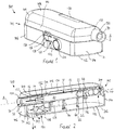
- Figures 1 and 2 show a device 100 according to the invention in a starting state.
- the device 100 comprises a housing 102 formed from an upper housing part or cover 104 and a lower housing part or chassis 106.
- the cover 104 and the chassis 106 fit together to enclose an interior of the device 100, with the cover 104 shaped and dimensioned to slide with respect to the chassis 106 in a telescoping arrangement.
- the cover 104 includes a top face 108 and a downwardly-projecting skirt 110 arranged around the periphery of the top face 108.
- the chassis 106 includes a baseplate 111 that is bordered by an upstanding wall 114. With the cover 104 and the chassis 106 fitted together and with the device in the starting state of the device 100, the top face 108 and the baseplate 111 are parallel and a top part of the upstanding wall 114 overlaps with a bottom part of the skirt 110 as shown most clearly in Figure 2 .
- the underside of the baseplate 111 of the chassis 106 forms a contact face 112 of the device 100 that is held against an injection site in use, as will be described below.
- a trigger lever 120 is disposed on a side of the device 100.
- the trigger lever 120 is formed in the wall 114 of the chassis 106 by way of suitable cut-outs.
- the trigger lever 120 is attached to the wall 114 by a pair of stays 122, arranged on opposite upper and lower sides of the trigger lever 120 along a vertical axis.
- a first end of the trigger lever 120 is enlarged to form a generally circular trigger button 124.
- a second end of the trigger lever 120 forms a blocking member 126.
- the trigger button 124 can be pushed towards the interior of the housing 102 to pivot the trigger lever 120 about the vertical axis defined by the stays 122. Pivoting of the trigger lever 120 results in twisting of the stays 122, generating a torsional restoring force that urges the trigger lever 120 back to a neutral position if the trigger button 124 is released.
- a portion of the wall 114 of the chassis 106 Adjacent to the trigger lever 120, a portion of the wall 114 of the chassis 106 is deflected outwardly to define a vertical channel or recess 128 that opens to the interior of the housing 102 (as can be seen most clearly in Figure 2 ).
- An outwardly-projecting stop 130 visible in Figure 1 , is disposed on the skirt 110 of the cover 104. The stop 130 is positioned to be disposed at the top of the recess 128 when the device 100 is in the starting state.
- the blocking member 126 extends into the recess 128 to prevent downward movement of the stop 130, and hence downward movement of the cover 104 with respect to the chassis 106 cannot occur.
- a carriage assembly 200 is housed in the interior of the housing 102.
- Figure 2 shows the carriage assembly 200 in situ in the housing 102
- Figure 3 shows an exploded view of the carriage assembly 200.
- the carriage assembly 200 includes a medicament container in the form of a pre-filled syringe 10.
- the syringe 10 comprises a generally tubular glass body or barrel 12 that defines a container axis A.
- the barrel 12 is formed into a reduced-diameter end portion 14 that carries a staked cannula in the form of a hypodermic needle 16.
- the barrel 12 is filled with a quantity of medicament 20 and is closed by a stopper 22 that is slidably received in the barrel 12 to act as a piston member.
- An outwardly-projecting flange 24 is provided at the end of the barrel 12 opposite the needle 16.
- a removable needle shield 30 (see Figure 2 , not shown in Figure 3 ) is provided to seal the needle 16 to maintain the sterility of the needle 16 and the medicament 20 in the container 10.
- the shield 30 comprises an elastomeric insert 32 and a rigid cap 34, and is known in the art as a rigid needle shield.
- the shield 30 is attached to the end portion 14 of the barrel 12, and extends out of the housing 102 through an aperture 132 in the cover 104.
- the syringe 10 may be of a type generally known in the art, for example as available under the registered trade mark Hypak (Becton Dickinson, New Jersey, USA), and may be supplied in pre-filled form with the needle shield 30 fitted.
- a window 134 in the cover 102 allows part of the syringe barrel 12 to be viewed from outside the device 100.
- the device 100 also includes a removable deshielder cap or sleeve 150 that is concentrically arranged around the needle shield 30.
- the sleeve 150 is generally tubular, and is provided with clips or barbs 152 on the inside wall of the sleeve 150, adjacent to its inner end. The barbs 152 are arranged to engage the cap 34 of the needle shield 30.
- An outside end part of the sleeve 180 extends through the aperture 132 in the cover 104 and beyond the end of the needle shield 30 to protrude out of the housing 102.
- the sleeve 150 can be gripped and pulled away from the housing 102 along the container axis A. In this way, the sleeve 150 comprises a user-removable component of the device 100. As the sleeve 150 is withdrawn from the housing 102, the barbs 152 engage with the cap 34 of the needle shield 30 so that the needle shield 30 is pulled off the syringe 10 and removed from the device 100.
- the carriage assembly 200 includes a carriage body 202 having an upper carriage body part 204 and a lower carriage body part 206 that fit together in a clamshell arrangement to retain the syringe 10 and to house a cannula or needle bending mechanism 300 and a drive mechanism 400 of the device 100.
- the carriage body 202 is attached to the cover 104 by means of screws or other suitable fixings (not shown), so that the carriage assembly 200 and the cover 104 are fixed together.
- the syringe 10 is arranged in a cut-out region 210 of the carriage body 202.
- Each carriage body part 204, 206 includes a first ring part 212 and a second ring part 214 that extend into the cut-out region 210 to retain the syringe 10.
- Each of the first ring parts 212 is spaced from an end of the cut-out region 210 to define a slot 216.
- the flange 24 of the syringe 10 fits into the slot 216 to prevent movement of the syringe 10 with respect to the carriage body 202.
- the second ring parts 214 form a collar around the syringe body 12, adjacent to the end portion 14, to provide further support for the syringe 10.
- the needle 16 of the syringe 10 With the syringe 10 mounted to the carriage body 202, the needle 16 of the syringe 10 is aligned with the container axis A. It is therefore necessary to bend the needle 16 so that the end of the needle points towards the contact face 112 of the device 100 before an injection can take place. To this end, the needle bending mechanism 300 is operable to bend the needle 16 automatically upon removal of the deshielder sleeve 150 from the device.
- the needle bending mechanism 300 comprises a needle bending member 302 that is mounted laterally with respect to the syringe 10.
- the bending member 302 is slidably mounted in a generally cylindrical space 220 formed in an end portion of the carriage body 202.
- the cavity 220 is defined between upper and lower part-tubular holder sections 222, 224 of the upper and lower carriage body parts 204, 206, respectively.
- the bending member 302 is guided for axial movement with respect to the carriage body 202 along a bending axis B. Viewed from the top of the device, the bending axis B lies at right angles to the container axis A, although the bending axis B does not intersect the container axis A.
- the bending member 302 is generally cylindrical. A forward end of the bending member 302, closest to the container axis A, is shaped to provide a needle engaging formation 304. A blind bore 306 extends from the rear end of the bending member, opposite the forward end, to accommodate a needle bending spring 308 and part of a spring retainer 350, as will be described below.
- the needle engaging formation 304 includes a generally cylindrical, rod-like arbor or former 310 that extends from the forward end of the bending member 302 along the bending axis B, and a bending arm 312 that extends from the forward end of the bending member 302 parallel to the former 310 and offset from the bending axis B.
- the outer surface of the bending arm 312 is part-cylindrical and continuous with the outer surface of the remainder of the bending member 302, while the inner surface 314 of the bending arm 312, closest to the former 310, comprises a flat surface, referred to hereafter as a bending surface.
- the former 310 and the bending surface 314 of the bending arm 302 are spaced apart to define a slot 316 therebetween.
- the slot 316 has an open end at the forward end of the bending member 302.
- the bending member 302 moves into a cooperating position with respect to the needle 16 in which the needle 16 is received in the slot 316.
- the bending surface 314 of the bending arm 312 is chamfered or bevelled to form an inclined ramp 318 adjacent to the open end of the slot 316.
- the side of the former 310 that faces the bending arm 312 is similarly chamfered or bevelled at its forward end to form a corresponding inclined ramp 320 adjacent to the open end of the slot 316.
- the bending member 302 is also provided with a guide pin 322 that projects radially outwards from the cylindrical outside surface of bending member 302.
- a guide track 226 for the guide pin 322 is provided in the lower holder section 224.
- the guide track 226 comprises a generally L-shaped channel formed in the upper side of the lower carriage body part 206.
- the guide track 226 has a rear portion 228 that extends parallel to the bending axis B, and a forward portion 230 that extends part-way around the circumference of the cavity 220.
- the spring retainer 350 shown most clearly in Figure 5(b) , comprises an end plate 352 and an elongate guide rod 354 that extends from the centre of the end plate 352 along the bending axis B.
- a pair of diametrically-opposed, radially-extending key elements 356 are provided on the periphery of the end plate 352 to engage with corresponding slots 232 formed at the end of the cavity 220 in the lower holder section 224.
- a further key element 358 extends downwardly from the periphery of the end plate 352 to engage with the linear rear portion 228 of the guide track 226. In this way, the key elements 356, 358 prevent linear and rotational movement of the spring retainer 350 with respect to the carriage body 202.
- the needle bending spring 308 when assembled, is disposed concentrically around the guide rod 354.
- the guide rod 354 is slotted along its length to receive a rear end termination (not shown) of the needle bending spring 308.
- a similar slotted guide rod 324 is provided at the internal end of the blind bore 306 of the bending member 302 to receive a forward end termination (not shown) of the needle bending spring 308.
- the needle bending spring 308 acts both in compression and torsion, and in this example comprises an open-coil helical spring. During assembly, the needle bending spring 308 is compressed and twisted so that the needle bending spring 308 applies both an axial force and a torque to the bending member 302.
- the bending member 302 In the starting state of the device 100, the bending member 302 is held in a retracted position by the deshielder sleeve 150. In the retracted position, the guide pin 322 of the bending member 302 is within the linear rear portion 228 of the guide track 226, so that turning movement of the bending member 302 about the bending axis B is prevented and the torsion in the needle bending spring 308 is maintained by virtue of the engagement between the end terminations of the spring 308 with the slotted guide rods 324, 354. The bending member 302 is spaced away from the container axis A and separated from the needle 16 by the deshielder sleeve 150 and the needle shield 30.
- the bending member 302 When the deshielder sleeve 150 is removed during operation of the device, the bending member 302 is free to move axially along the bending axis B under the force applied by the needle bending spring 308.
- the needle engaging formation 304 thus moves into an overlapping position with respect to the container axis A, so that the needle 16 is guided into the slot 316 between the former 310 and the bending arm 312.
- the guide pin 322 moves along the linear rear portion 228 of the guide track 226, so that the bending member 302 cannot rotate about the bending axis B.
- the turning movement of the bending member 302 causes the bending arm 312 to apply a bending force to the needle 16.
- the bending force causes the needle 16 to bend against the cylindrical former 310.
- the needle 16 conforms to the shape of a part-cylindrical section of the surface of the former 310, creating a smooth bend in the needle 16 that does not substantially restrict fluid flow through the needle.
- Figures 6 and 7 show the device 100 after the deshielder sleeve 150 has been removed and when movement of the bending member 302 with respect to the carriage body 202 is complete.
- the needle 16 has been bent around the former 310 through an angle of approximately 90 degrees, so that the free end of the needle 16 now extends in an insertion direction H that is perpendicular to the container axis A.
- the radius of curvature of the needle 16 after operation of the bending mechanism 300 is determined by the radius of the former 310, and the angle through which the needle 16 is bent is determined by the angle through which the bending member 302 turns. It will be appreciated that the needle 16 will tend to bend through a slightly smaller angle than the turning angle of the bending member 302 as a result of component clearances, manufacturing tolerances and elastic deformation of the components. Accordingly, in the illustrated example, the forward portion 230 of the guide track 226 (see Figure 5(b) , not shown in Figure 6 ) is dimensioned so that the bending member 302 turns through an angle of approximately 95 degrees in total, which results in the needle 16 bending through an angle of approximately 90 degrees.
- the device 100 includes an insertion mechanism that is operable to apply an insertion force to the carriage assembly 200 to move the carriage assembly 200 in the insertion direction H with respect to the chassis 106 from a starting position, in which the needle 16 is shrouded, to an insertion position, in which the needle 16 extends through an aperture 116 disposed in the baseplate 111 of the chassis 106.
- the device 100 also includes a safety interlock mechanism that prevents accidental operation of the insertion mechanism.
- the insertion mechanism includes an insertion spring 70.
- the insertion spring 70 comprises a tension spring that is arranged vertically in the housing 102 and attached between the carriage assembly 200 and the lower housing part 106.
- the insertion spring 70 has a lower hooked end termination that engages with a spring hook 118 formed on the top side of the baseplate 111 of the chassis 106 (see also Figure 6 ).
- the insertion spring 70 extends through the carriage body 202, so that an upper hooked end termination 74 of the insertion spring 70 is disposed on the upper side of the carriage body 202.
- a spring tube 240 is provided in the lower carriage body part 206 and a circular aperture 242 is provided in the cover 104 to allow the insertion spring 70 to pass through the carriage body 202.
- the upper end termination 74 of the insertion spring 70 is attached to a pin part 502 of a spring coupling member 504.
- the spring coupling member 504 forms part of a retraction mechanism of the device, and is mounted on the top side of the upper carriage body part 204. In this way, the insertion spring 70 acts to bias the carriage assembly 200 in the insertion direction H.
- Movement of the cover 104, and hence also the carriage assembly 200, in the insertion direction H is initially prevented by the blocking member 126 of the trigger lever 120, which blocks movement of the stop 130 of the cover 104 along the channel 128 in the chassis 106, as explained above with reference to Figures 1 and 2 .
- the carriage assembly 200 is held in its starting position with respect to the chassis 106.
- the interlock mechanism 170 which is arranged to prevent operation of the trigger lever 120 until the device 100 has been correctly positioned against an injection site, will now be described with reference to Figures 8 and 9 .
- the interlock mechanism 170 is mounted on the upper side of the baseplate 111 of the chassis 106.
- the interlock mechanism 170 comprises a sensor element or sensor collar 172 that is received in the aperture 116 of the chassis 106.
- the sensor collar 172 is annular to define a central opening 174, to allow the needle 16 (not shown in Figure 8 ) to pass through the sensor collar 172 upon insertion.
- the sensor collar 172 has an enlarged-diameter rim 176 on its upper side to retain the sensor collar 172 in the housing 102.
- a lower part of the sensor collar 172 is dimensioned to fit through the aperture 116, as can also be seen in Figure 9(a) .
- a leg 192 extends upwardly from one side of the sensor collar 172. Referring additionally to Figure 2 , the leg 192 is dimensioned so that the leg 192 cooperates with the deshielder sleeve 150 when the deshielder sleeve 150 is still in place.
- the sensor collar 172 is coupled to a beam element 178.
- the beam element 178 is angled, with a first section 180 extending from the sensor collar 172 towards a pivot 182, and a second section 184 extending from the pivot 182 towards a free end 186 that is disposed next to the inner face of the button 124 of the trigger lever 120.
- the beam element 178 is attached to the sensor collar 172 by means of a pin (not shown) on the beam element 178 that engages with a corresponding hole (not shown) in the sensor collar 172.
- the beam element 178 is attached to the chassis 106 at the pivot 182, for example by a clip.
- the beam element 178 is biased by a pair of flat springs 188 that extend between the wall 114 of the chassis 106 and respective guide blocks 190 provided on the upper side of the baseplate 111 of the chassis 106.
- One end of each flat spring 188 is connected to the free end 186 of the beam element, and the opposite end of each flat spring 188 bears against the upper side of the baseplate 111 of the chassis 106, urging the free end 186 of the beam element in the upward direction and the sensor collar 172 in the downward direction.
- the interlock mechanism 170 is biased into a first state, shown in Figures 8(a) and 9(a) , in which the sensor collar 172 projects from the contact face 112 (i.e. the bottom face of the sensor collar 172 stands proud of the contact face 112) and the free end 186 of the beam element 178 is positioned to block inward movement of the trigger button 124.
- the interlock mechanism 170 prevents unintentional operation of the trigger button 124, with the free end 186 of the beam element 178 acting as a trigger blocking element.
- the interlock mechanism 170 can be switched into a second state, shown in Figures 8(b) and 9(b) , in which the free end 186 of the beam element 178 no longer blocks inward movement of the trigger button 124.
- the sensor collar 172 thus acts as a sensor that responds to detection of the skin at the injection site S by switching the interlock mechanism 170 from the first state to the second state. It will be appreciated that the sensor collar 172 may not retract fully into the chassis 106 when in the retracted position, and that the bottom face of the sensor collar 172 may instead still be slightly proud of the contact face 112. However, a substantial majority of the contacting area between the device 100 and the injection site is through the contact face 112 itself.
- the flat springs 188 cause the interlock mechanism 170 to return to the first state, to block operation of the trigger button 124 once more.
- Figure 10(a) shows another view of the device 100 when the contact face 112 has been pressed against an injection site, so that the interlock mechanism 170 is held in the second state. Only the beam element 178 of the interlock mechanism 170 can be seen in Figure 10(a) .
- the trigger lever 120 is still in its neutral position, with the blocking member 126 preventing movement of the stop 130 down the channel 128.
- Figures 11 and 12 show further views of the device 100 at the end of the insertion stroke.
- Figure 11 illustrates the low-profile configuration of the device, with the cover 104 now telescoped fully into the chassis 106.
- the chassis 106 does not move during the insertion stroke, so that the contact face 112 of the device 100 remains stationary with respect to the injection site.
- movement of the carriage assembly 200 in the insertion direction H causes the bent needle 16 to extend out of the aperture 116 in the baseplate 111 of the chassis 106, passing through the opening 174 in the sensor collar 172.
- the needle 16 protrudes from the contact face 112 of the device 100 to pierce the skin at the injection site.
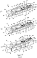
- Delivery of the medicament 20 through the needle is performed by operation of the drive mechanism 400 of the device 100, as will now be described with reference to Figures 3 and 4 , and also with reference to Figure 13(a) , which shows the device 100 at an intermediate position during the insertion stroke, before activation of the drive mechanism 400, such that the drive mechanism 400 is in an initial, unfired state.
- the drive mechanism 400 includes a drive means in the form of a drive spring 40 that is arranged alongside the syringe 10 and along a drive axis D that is parallel to the container axis A.
- the drive spring 40 is housed in a generally cylindrical cavity 208 in the carriage body 202.
- the drive mechanism 400 further includes a guide tube 402, a piston member 404 that is slidably received in the guide tube 402, and a force transmission means comprising a plurality of balls 406 arranged in a linear array along a J-shaped guide track 408 (see Figures 3 and 4 ).
- the guide track 408 is defined in part by the upper and lower carriage body parts 204, 206 and in part by the guide tube 402.
- the guide tube 402 is received in the cylindrical cavity 208 of the carriage body 200, inside the drive spring 40.
- the guide tube 402 accommodates several of the balls 406 and defines a long linear portion of the guide track 408.
- the carriage body parts 204, 206 are shaped to define a U-shaped part 410 of the guide track 408 that extends from the cylindrical cavity 208 and around a sprocket 550, and opens into the bore of the syringe barrel 12.
- the balls 406 are sized to fit within the bore of the syringe barrel 12.
- the piston member 404 is received in the end of the guide tube 402 closest to the needle bending mechanism 300.
- the piston member 404 comprises an end face 412 that is cup-shaped for cooperation with the closest one of the balls 406.
- a rib 414 (see Figure 3 ) is provided on the upper side of the piston member 404.
- the guide tube 402 includes a slit 416 that extends parallel to the drive axis D to receive the rib 414, so that the piston member 404 can slide within the guide tube 402 without rotating about the axis of the guide tube 402.
- the piston member 404 is biased along the drive axis D and away from the needle bending mechanism 300 by the drive spring 40.
- the drive spring 40 comprises a helical tension spring with hooked end terminations and is accommodated concentrically around the linear portion of the guide track 408, in the space between the guide tube 404 and the cylindrical cavity 208 in the carriage body 202. In this way, the guide tube 404 also acts as a spring guide for the drive spring 40.
- One end termination 42 of the drive spring 40 is hooked into an aperture 252 in the upper carriage body 204 (see Figure 3 ).
- the opposite end termination 44 of the drive spring 40 passes through a slot 420 in the upper side of the piston member 404 to locate in a frustoconical bore 422 of the piston member 404.
- the drive spring 40 is stretched along its length to store energy and, as will be described in more detail below, is arranged to apply a linear force to the piston member 404 along the drive axis D when the drive mechanism 400 is operated.
- the piston member 404 is provided with a pair of spring fingers 424 disposed on either side of the slot 420 on the rear side of the piston member 404, and a latch formation 426 that extends along the front side of the piston member 404.
- the spring fingers 424 and the latch formation 426 can also be seen in Figure 10 .
- the latch formation 426 extends through an aperture 254 in the carriage body 202 (see also Figure 3 , in which the position of the aperture 254 in the lower carriage body part 206 can be seen).
- the latch formation 426 has a hook-shaped head arranged to releasably engage with a stop 256 formed on the lower carriage body part 206 at the side of the aperture 254.
- the spring fingers 424 press against the upper side of the aperture 254 to keep the latch formation 426 in engagement with the stop 256 on the lower carriage body 206.
- the latch formation 426 prevents linear movement of the piston member 404 under the influence of the drive spring 40 when the head of the latch formation 426 is engaged with the lower carriage body 406.
- a firing block 260 is provided on the baseplate 111 of the chassis 104. As will be explained in more detail below, the firing block 260 is positioned to cooperate with the latch formation 426 to release the piston member 404 for movement along the drive axis D in a delivery stroke during the operating sequence of the device 100.
- a shock absorber cup 430 is received in the barrel 12 of the syringe 10, between the stopper 22 and the array of balls 406.
- One face 432 of the shock absorber cup 430 is shaped to cooperate with the closest one of the balls 406.
- the shock absorber cup 430 is of a plastics foam material, for example a polyurethane foam, to cushion the impact between the balls 406 and the stopper 22 upon activation of the drive mechanism 400.
- the balls 406 are arranged along the guide track 408 to form a chain or array.
- the periphery of the sprocket 550 is shaped to cooperate with the balls 406 in the adjacent track 408, so that movement of the balls 406 along the guide track 408 turns the sprocket 550.
- the sprocket forms part of a retraction mechanism of the device, which will be explained in more detail below.
- the ball 406 at the end of the array closest to the piston member 404 is spaced from the face 412 of the piston member 404, and the ball 406 at the other end of the array is spaced from the face 432 of the shock absorber cup 430. It will however be appreciated that the balls 406 are not attached to one another and that the spacing of the balls 406 may differ in practice. In preferred arrangements, smaller clearances than those shown are present between the respective contact faces 412, 432 and the corresponding balls 406.
- the contact faces 412, 432 can be in contact with the corresponding balls 406, in which case the shock absorber cup 430 can deform to take up any difference in length between the array of balls 406 and the distance between the faces 412, 432 when the components are in their initial positions.
- the drive mechanism 400 is automatically triggered during movement of the carriage assembly 200 towards the contact face 112 of the device 100.
- the carriage assembly 200 reaches an activation position in which the firing block 260 on the chassis 106 comes into contact with the head of the latch formation 426 on the piston member 404 (see Figure 13(a) ).
- the firing block 260 displaces the latch formation 426 towards the top face 108 of the device 100, bending the spring fingers 424 and causing the latch formation 426 to disengage from the stop 256 on the lower carriage body part 206, as shown in Figure 13(b) .
- the drive mechanism 400 of the device 100 is activated, and linear movement of the piston member 404 within the guide tube 402 under the load of the drive spring 40 can now take place.
- the piston member 404 moves along the guide tube 402 in a delivery stroke, the piston member 404 pushes the balls 406 around the guide track 408 and into the syringe barrel 12.
- the load of the drive spring is thus transferred through the array of balls 406 to the ball 406 closest to the shock absorber cup 430.
- the shock absorber cup 430 pushes the stopper 22 of the syringe 10 distally to expel medicament through the needle 16.
- the shock absorber cup 430 reduces the risk of impact damage to the syringe 10 and reduces the impact sound.
- a retraction mechanism of the device 100 operates to retract the needle 16 from the injection site. The components and operation of the retraction mechanism will now be described.
- Figure 14 shows the device 100 sectioned through a vertical plane of the device that is parallel to and mid-way between the container axis A and the drive axis D.
- a pair of retraction springs 60 are provided to bias the carriage assembly 200 away from the contact face 112 of the device 100, in a direction opposite to the insertion direction H.
- each retraction spring 60 is a helical compression spring, and is mounted on a corresponding guide pin 62 that extends upwardly from the baseplate 111 of the chassis 106.
- the carriage body 202 includes a pair of tubular guides 261 for receiving the retraction springs 60 and the corresponding guide pins 62.
- Each guide 261 has an inwardly-directed flange 262 at its upper end to provide a seat for the respective retraction spring 60.
- the combined force applied to the carriage assembly 200 by the retraction springs 60 is less than the force applied to the carriage assembly 200 by the insertion spring 70, so that the force of the insertion spring 70 overcomes the force of the retraction springs 60 during the insertion stroke of the carriage assembly 200.
- the retraction springs 60 are compressed between the carriage body 202 and the baseplate 111 of the chassis 106 during the insertion stroke.
- the insertion spring 70 is coupled to the carriage body 202 by way of a spring coupling member 504 having a pin part 502, with the upper end termination 74 of the insertion spring 70 hooked over the pin part 502.
- the coupling member 504 is slidable with respect to the carriage body 202. In this way, during operation of the retraction mechanism, the pin part 502 of the coupling member 504 can be withdrawn from engagement with the insertion spring 70 to decouple the insertion spring 70 from the carriage assembly 200.
- the coupling member 504 is mounted on the upper side of the upper carriage body part 204 and is guided for linear movement thereon by a channel 270, visible only in Figure 3 .
- a lower part of the coupling member 504 extends into the channel 270, and the coupling member 504 is secured in the channel 270 by attachment of the lower part of the coupling member 504 to a bracket 506.
- the bracket 506, in turn, is in sliding engagement with a guide rod 272 that is formed on the spring tube 240 on the lower carriage body part 206. Both the channel 270 and the guide rod 272 extend parallel to the container axis A and the drive axis D.
- a decoupling spring 80 in the form of a helical compression spring, is disposed concentrically around the guide rod 272.
- the decoupling spring 80 bears against the bracket 506 at one end and against the spring tube 240 at its opposite end, so that the coupling member 504 is biased for linear movement in a direction away from the needle bending mechanism 300.
- the release lever 520 Before activation of the retraction mechanism, movement of the coupling member 504 is prevented by a release lever 520.
- the release lever 520 comprises a ring-shaped hub 522, a blocking finger 524 that extends away from the hub 522 towards the coupling member 504, and a release arm 526 that extends away from the hub 522 generally in the opposite direction to the blocking finger 524.
- a flat spring 528 is also provided, which extends from the hub 522 alongside the release arm 526.
- the release lever 520 is mounted on the upper carriage body part 204, with the hub 522 fitted over the top end of one of the tubular retraction spring guides 261.
- the flat spring 528 bears against a vertical surface 264 of the upper carriage body part 204.
- the flat spring 528 biases the release lever 520 so that the release arm 526 contacts a stop formation 276 (not shown in Figure 16 ) on the upper carriage body part 204. As shown most clearly in Figure 15(a) , when the release lever 520 is in this position, the blocking finger 524 abuts the coupling member 504, resisting movement of the coupling member 504 under the influence of the decoupling spring 80.
- the sprocket 550 which is driven to rotate by the balls 406 during medicament delivery, is provided on its upper side with a pinion gear 552.
- the pinion gear 552 extends through an aperture 278 in the upper carriage body part 204 (see Figure 3 ).
- the pinion gear 552 drives a wheel in the form of an annular gear 554 that is retained by a part-circular guide wall 280 on the upper carriage body part 204.
- the outer edge of the annular gear 554 is formed with an annular groove 556 to accept a reduced-thickness tip 558 of the release arm 526 of the release lever 520.
- the groove 556 of the annular gear 554 is interrupted at one position by a tab 560.
- the tab 560 is initially disposed to the left of the tip 558 of the release arm 526 (as viewed in Figure 15(a) ).
- the sprocket 550 and the pinion 552 are driven to rotate in a clockwise direction.
- the pinion 552 drives the annular gear 554 (with, in this example, a 1.5:1 reduction in gear ratio), which likewise rotates in a clockwise direction. This move the tab 560 clockwise.
- the annular gear 554 rotates through a smaller angle than the sprocket 550.
- the sprocket 550 rotates through approximately 1.5 turns during operation of the drive mechanism 400, and this causes approximately one full turn of the annular gear 554.
- the tab 560 engages with the tip 558 of the release arm 526 of the release lever 520. This causes the release lever 520 to pivot in an anticlockwise direction, moving the blocking finger 524 out of engagement with the coupling member 504. Thus the coupling member 504 is released for movement under the bias of the decoupling spring 80.
- a rotary damper 570 is provided to control the speed of movement of the coupling member 504.
- the rotary damper 570 is mounted on the upper side of the coupling member 504, and comprises a toothed rotary element or cap 572 that is engaged with a rack 282 formed on the upper carriage body part 204.
- the cap 572 encloses a chamber (not shown) that contains a viscous fluid, such as silicone grease.
- the coupling member 504 moves linearly with respect to the carriage body 202
- the cap 572 is driven to rotate by the rack 282, and is arranged to move an internal vane 283 (see Figure 15(a) ) through the viscous fluid in the chamber, which resists movement of the cap 572 and hence retards the speed of the coupling member 504.
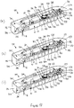
- Figure 17(a) shows the device 100 mid-way through medicament delivery, when the plunger 22 has been driven partially down the body 12 of the syringe 10.
- the coupling member 504 is still held in its initial position by the release lever 520, and the retraction spring 70 (only the upper end termination 74 of which can be seen in Figure 17(a) ) is still hooked over the pin part 502 of the coupling member 504.
- the sprocket 550 has been rotated by the balls 406 of the drive mechanism and the pinion 552 has driven the annular gear 554 to move the tab 560 clockwise from its initial position.
- Figure 17(b) shows the device 100 during a later stage of medicament delivery, in which further rotation of the sprocket 550 has resulted in further rotation of the annular gear 554, bringing the tab 560 closer to the tip 558 of the release arm 526 of the release lever 520.
- Figure 17(c) shows the device 100 at a still later stage of medicament delivery.
- further rotation of the annular gear 554 has brought the tab 560 into contact with the tip 558 of the release arm 526, and the tab 560 has displaced the release arm 526 against the bias of the flat spring 528 to activate the retraction mechanism.
- the blocking finger 524 no longer blocks movement of the coupling member 504.
- the coupling member 504 begins to move towards the sprocket 550 under the bias of the decoupling spring 80.
- the blocking finger 524 moves clear of the coupling member 504 before the movement of the piston member 404 (not shown in Figure 17 ) ends. In this way, it is ensured that the coupling member 504 will always be released for linear movement before the delivery stroke ends, even accounting for manufacturing tolerances and the like. In one example, the blocking finger 524 moves clear of the coupling member 504 when the piston member 404 is approximately 1 mm from the end of its travel.
- the pin part 502 of the coupling member 504 is withdrawn from the upper end termination 74 of the insertion spring 70, as shown in Figure 17(e) , to decouple the insertion spring 70 from the carriage assembly 200.
- the insertion spring 70 no longer applies a force to the carriage assembly 200, so that the carriage assembly 200 moves upwardly, opposite to the insertion direction H, under the force applied by the retraction springs 60.
- the upward movement of the carriage assembly 200 causes withdrawal of the needle 16 from the injection site, as shown in Figure 17(f) .
- the cover 104 (not shown in Figure 17 ) "pops up" with the carriage assembly 200 to provide a visual and tactile indication to the user that medicament delivery has been completed and that the device 100 can be removed from the injection site.
- the cover 104 is retained by suitable stop features (not shown), disposed for example on the periphery of the cover 104 and the chassis 106.
- the needle 16 is now safely retracted within the housing 102, and the device 100 can be disposed of.
- the provision of the damper 570 creates a time delay between activation of the retraction mechanism (i.e. displacement of the release arm 526 by the tab 560) and the decoupling of the insertion spring 70 to retract the needle 16.
- This time delay ensures complete delivery of the medicament, by allowing the delivery stroke to end and allowing the needle 16 remain in place in the injection site for a short period after end of the delivery stroke before retraction of the needle 16.
- a time of 3 to 4 seconds elapses between the blocking finger 524 moving clear of the coupling member 504 and the pin part 502 of the coupling member 504 decoupling from the insertion spring 70, although a longer or shorter delay could be provided if desired.
- the retraction springs 60, the sprocket 550 and gears 552, 554, the releasable coupling arrangement formed by the release lever 520 and the coupling member 504 and the decoupling spring 80 together form a retraction mechanism for the device 100 that, after activation, moves the carriage assembly 200 in a retraction direction opposite to the insertion direction H.
- the rotary damper 570 defined by the cap 572 and the rack 282 provide a time delay mechanism that creates a delay time between activation of the retraction mechanism, and the start of movement of the carriage assembly 200 in the retraction direction.
- the components of the device are selected and arranged to provide a device with a low-profile form factor.
- the device can be comfortably gripped and held stationary against an injection site by a user, held in place with a suitable strap or holder, affixed to the injection site with adhesive tape, or adhered to the injection site with an adhesive applied to the contact face 112 of the device 100.
- the relatively large surface area of the contact face 112 of the device 100 means that the device 100 can be held firmly against the injection site with minimal discomfort and marking, since the holding force is spread over a large area.
- the device is particularly suitable for the delivery of relatively large volumes of medicament over a relatively long period of time.
- impact loads that may occur upon insertion of the needle, in particular at the end of the insertion stroke when the cover 104 contacts the chassis 106 are dissipated over the large area provided by the contact face 112, minimising the impression of such loads on the user.
- cushioning elements may be provided to act as shock absorbers between impacting components.
- cushioning elements may be provided on the lower edge of the skirt 110 of the cover 104 or at the periphery of the baseplate 111 of the chassis 106.
- cushioning elements may be provided between the retraction spring guide pins 62 and the flanges 262 of the corresponding guides 260.
- the cushioning elements may be formed from an elastomeric foam material, such as a polyurethane foam.
- a single needle bending spring that acts in both compression and torsion is used to drive movement of the bending member of the needle bending mechanism.
- two springs can be provided for this purpose.
- a compression spring can be used to drive axial movement of the bending member along the bending axis
- a torsion spring can be used to drive turning movement of the bending member about the bending axis.
- the guide track can be shaped to provide a cam action to assist or drive turning movement of the bending member.
- the needle drive spring could be a tension spring.
- other spring types or alternative energy storage means could be used.
- Part or all of the movement of the bending member could be manually driven, for example by direct manipulation of a shaft part of the bending member, or indirectly through a suitable mechanism.
- operation of the bending mechanism is activated by removal of a user-removable component in the form of a deshielder shield.
- the user-removable component could instead be a safety tab or a packaging part.
- a retaining means such as a releasable or removable clip may be provided to hold the bending mechanism in its initial state.
- operation of the bending mechanism could be triggered by a specific action, such as operation of a button or slider, on the part of the user. It is also conceivable that axial movement of the bending member could be triggered automatically upon removal of the deshielder to engage the bending member with the needle, whilst the turning movement to bend the needle could be triggered separately.
- the bending mechanism can be arranged to produce substantially any desired cannula or needle shape and angle through appropriate design of the needle engagement formation of the bending member and the guide track and other parameters, such as the orientation of the bending axis with respect to the container axis. It is also conceivable that the cannula could be pre-bent or otherwise arranged for alignment with the insertion direction, in which case the bending mechanism could be omitted from the device.
- the carriage assembly moves in the downward direction with respect to the contact surface to insert the needle and in the upward direction to withdraw the needle.
- the insertion direction may be at a non-perpendicular angle to the container axis.
- the needle would be bent through a corresponding non-perpendicular angle.
- any suitable arrangement that first holds the carriage assembly in the starting position and then releases the carriage assembly for movement in the insertion direction could be used. Whilst in the illustrated example, the trigger arrangement acts against the cover, the trigger arrangement could instead act against the carriage body or another part of the carriage assembly.
- the trigger arrangement could be mounted on the top face of the device or on one of the end sides of the device. A lever, button, slider, knob or any other suitable trigger component could be used to operate the trigger arrangement. More than one trigger component could be provided.
- trigger components could be provided on each side of the device, and release of the carriage assembly could be achieved by manipulation of either one of the trigger components (for example to allow left- or right-handed use), or upon simultaneous manipulation of both trigger components (to provide additional security against accidental operation of the device).
- the interlock mechanism acts directly to block movement of the trigger lever.
- other suitable interlock mechanisms can be contemplated that would allow movement of the trigger lever but otherwise prevent movement of the carriage assembly from the starting position. It is also conceivable that the interlock mechanism could be omitted.
- the drive spring need not be arranged concentrically around a part of the array of balls.
- the drive member could be driven by one or more tension springs arranged alongside a part of the array of balls.
- the drive member could be driven by a compression spring, constant force spring, power spring or any other suitable means for applying a force.
- any suitable releasable latch or retaining arrangement may be used to hold the piston member in its initial position and to release the piston member for movement along the drive axis.
- the piston member may be retained by a retaining pin or other retaining means that moves out of engagement with the piston member when the carriage assembly moves in the insertion direction to activate the drive mechanism and transfer the force of the spring to the balls to drive the stopper of the syringe.
- Other drive arrangements that do not use a piston member are also possible.
- the sprocket could be driven by a driving element, such as a power spring, to apply a drive force to the balls or other force transmission means.
- an array of balls is provided to transmit force from the piston member to the stopper of the syringe.
- the balls are metal ball bearings, which allow transmission of the force with minimal flexing or elastic deformation.
- other force transmission means could be provided.
- a flexible plastic rod, a close-wound spring, a link chain or any other suitable arrangement could be used.
- the force transmission means could be integral with or fixed to the piston member.
- the drive axis along which the piston member moves is parallel to and spaced from the axis of the container, along which the stopper moves to expel the medicament.
- the piston member is disposed alongside the container, and the piston member and the stopper move in opposite directions relative to the carriage body.
- the force transmission means serves to redirect the force of the drive spring through 180 degrees. This results in a relatively compact arrangement.
- other arrangements of the components within the carriage are possible, including those in which the drive axis and the container axis are non-parallel, or in which the drive axis and the container axis are coaxial.
- a rotary damper provides a compact and predicable means for introducing a delay time between activation of the retraction mechanism and the retraction movement of the needle.
- the damping fluid is selected such that the viscosity of the damping fluid is not substantially changed over the range of temperatures in which the device might be expected to be used, which may include use straight after removal of the device from a refrigerator and/or use of the device in relatively hot environmental conditions.
- time delay mechanisms could be used.
- a rotary damper instead of a linear viscous damper or other damping arrangement could be used.
- an escapement mechanism, gear train or other mechanical delay arrangement could be used.
- a time delay mechanism may not be required, in which case the insertion spring could be decoupled from the carriage arrangement substantially immediately upon activation of the retraction mechanism.
- the retraction mechanism could be omitted, and the needle could be withdrawn manually after delivery of the medicament.
- An outer casing may be provided over the cover, so that the dimensions of the device do not change in use.
- Such an outer casing may be transparent or include a window to allow movement of the cover to be seen by the user during operation of the device.
- the above-described examples show the device in use with a pre-filled syringe having a permanently attached needle, but the assembly could equally be used with other arrangements, such as a medicament container with a separate, attachable or connectable needle or cannula. To this end, in some arrangements, the container and/or the drive mechanism need not be retained by or moveable with the carriage.
Landscapes
- Health & Medical Sciences (AREA)
- Heart & Thoracic Surgery (AREA)
- Vascular Medicine (AREA)
- Engineering & Computer Science (AREA)
- Anesthesiology (AREA)
- Biomedical Technology (AREA)
- Hematology (AREA)
- Life Sciences & Earth Sciences (AREA)
- Animal Behavior & Ethology (AREA)
- General Health & Medical Sciences (AREA)
- Public Health (AREA)
- Veterinary Medicine (AREA)
- Dermatology (AREA)
- Infusion, Injection, And Reservoir Apparatuses (AREA)
Description
- The present invention relates to devices suitable for the delivery of a medicament to a patient. In particular, but not exclusively, the invention relates devices in which activation of the device causes automatic insertion of a cannula to an injection site and delivery of the medicament by injection through the cannula.
- Injection devices designed for automatic needle insertion and injection of a single pre-determined dose of a medicament are known in the art as auto-injectors. Such devices typically include a housing that allows the user to grip the device, a pre-filled syringe containing the medicament, and a drive mechanism. The pre-filled syringe includes a tubular glass barrel with a staked hypodermic needle at its distal end, a needle shield to protect and seal the needle, and a stopper slidably received in the barrel. One example of a pre-filled syringe of this type is available under the registered trade mark Hypak (Becton Dickinson, New Jersey, USA).
- The syringe is axially movable within the housing between an initial, retracted position in which the needle is retracted in the housing, and a deployed position in which the needle projects from the end of the housing.
- With the syringe in the retracted position, the distal end of the housing is closed by a cap. To prepare the device for use, the cap is removed. The cap is arranged to grip the rigid needle shield, so that removal of the cap pulls the rigid needle shield off the needle.
- The distal end of the housing is then placed against the skin, and the user operates a trigger of the device, such as a button, to activate the drive mechanism. The drive mechanism typically comprises a plunger that is biased in the distal direction by a compression spring. The plunger is initially held in an initial, latched position by a latch arrangement. Upon activation of the drive mechanism, the plunger is released from the latched position and can move distally under the force of the compression spring.
- Initially, release of the plunger causes the syringe to move from the retracted position into the deployed position, so that the needle pierces the skin. Subsequently, the plunger forces the stopper in the distal direction to inject the medicament.
- Some auto-injector devices also include a needle retraction mechanism to withdraw the needle from the skin and retract it into the device once the medicament has been delivered. A needle retraction mechanism typically includes a retraction spring and a coupling arrangement for coupling the retraction spring to the syringe. Once coupled, the retraction spring applies a force to the syringe that acts in the proximal direction to move the needle back towards the retracted position. The coupling arrangement may be activated to retract the needle when the plunger nears or reaches the end of its distal travel.
- Auto-injectors of these types can be convenient for self-administration by a patient of a measured dose of a medicament, although they may also be used by trained medical personnel. In both cases, auto-injectors typically offer increased user safety compared with traditional syringes, for example by ensuring that the needle used to deliver the medicament is shrouded before and/or after delivery of the medicament, and by the inclusion of interlock means or other safety devices to prevent accidental operation of the device.
- Existing auto-injector devices can however have several drawbacks. For example, the above-described drive mechanism results in a relatively long device, since the plunger and the compression spring are disposed in a coaxial arrangement with the syringe. For some applications, it would be desirable to provide a more compact and ergonomic arrangement.
- Another consequence of the linear arrangement of the device components is that the distal end of the device must be held firmly in contact with the injection site whilst the trigger is manipulated to activate the device and during subsequent delivery of the medicament. To ensure optimum needle penetration and to minimise discomfort, the body of the device should be held perpendicular to the injection site and with as little movement as possible. This may be relatively difficult for some users, such as individuals with reduced manual dexterity, impaired vision, and so on, and can be particularly problematic when injection takes place over a relatively long time period, such as when a high volume of medicament is to be delivered or when a high viscosity medicament is used.
- Furthermore, the force applied to the injection site through the relatively small contact area at the distal end of the device can be relatively high, potentially leading to discomfort and to the temporary marking of the skin.
- A relatively strong drive spring is usually required to ensure delivery of the medicament through the needle. This is particularly the case when the medicament has a relatively high volume, high viscosity and/or when the needle has a fine gauge. When a powerful drive spring is also used to drive insertion of the needle, the resulting impact loads on the syringe can lead to damage of the syringe and discomfort for the patient.
- Also, when a needle retraction mechanism is provided, there is a risk that retraction of the needle may occur before the whole of the desired dose of medicament has been delivered. For example, variations in component dimensions due to manufacturing tolerances can give rise to variations in the point at which needle retraction is triggered, which can result in premature retraction of the needle. The relaxation of elastic strain in the device components (in particular the stopper and the plunger) can result in medicament flow through the needle even after the plunger has nominally reached the end of its stroke, resulting in a failure to deliver the complete dose if the needle is retracted too rapidly after injection. Also, if the needle is retracted before the medicament has time to dissipate into the surrounding tissue, medicament can be lost from the injection site through the puncture.
-
WO 2013/032841 discloses a device for infusing a compound subcutaneously over an extended period of time. A conventional prefilled syringe with a staked cannula may be used, with the device adhered to the injection site and the syringe positioned substantially parallel to the injection site. The cannula is bendable by a mechanism integral to the device to provide a distal section that is substantially perpendicular to the syringe axis. -
US 2014/0088508 discloses a drug-delivery device for subcutaneous injections. The drug-delivery device is assembled from a pre-filled, standard drug vial, a plunger fitted into the vial, and a pump placed at the back end of the vial behind the plunger; the pump causes the plunger to move towards an outlet of the vial to expel liquid drug therefrom. The vial outlet is fluidically counected to the needle and/or cannula intended for insertion into the patient's sub-cutaneous tissue. The vial may be oriented parallel to the bottom wall of the device housing, which is, during use, placed against the user's skin. The needle and/or cannula may be disposed above or below, and parallel to, the vial. A curved needle guide may be used to bend the needle near its tip so as to guide it at an angle towards an opening in the bottom wall. - Accordingly, it would be desirable to provide an injection device that overcomes or mitigates some of the above-mentioned problems.
- Against this background, in a first aspect of the present invention there is provided a medicament delivery device for delivery of medicament from a container into an injection site through a cannula, the device comprising: a chassis; a drive mechanism for driving a piston member of the container along a container axis to expel the medicament through the cannula; a carriage for retaining the container, the cannula and the drive mechanism; an insertion mechanism for moving the carriage in an insertion direction relative to the chassis from a starting position; and a cannula bending mechanism for bending the cannula about a bending axis to substantially align at least an end part of the cannula with the insertion direction prior to movement of the carriage in the insertion direction, characterised in that the bending mechanism comprises a bending member that is axially moveable along the bending axis into engagement with the cannula and turnable about the bending axis to apply a bending force to the cannula, and wherein a user-removable component blocks axial movement of the bending member until the user-removable component has been removed from the device for triggering operation of the bending mechanism.
- By the incorporation of a cannula bending mechanism, the insertion direction need not be aligned with or parallel to the orientation of the cannula in a starting state of the device. Accordingly, the cannula and the container can be housed in any suitable orientation within the device, giving greater flexibility in the form factor of the device and in the selection of the medicament container and cannula arrangement. In particular, the device can be used to deliver medicament from a pre-filled container having an attached cannula or needle that is disposed coaxially with the container axis, without requiring that the insertion direction is parallel to the container axis. Thus a compact and/or low-profile device can be provided whilst using a widely-available medicament packaging in the form of a pre-filled syringe, such as a Hypak syringe, and the cost and time required to re-validate a medicament for supply in a bespoke medicament package can be avoided.
- The bending mechanism operates automatically during an operating sequence of the device. The user-removable component may be a deshielder for removing a shield from the cannula. In this way, removal of the deshielder both exposes the cannula internally and operates the bending mechanism to bend the cannula into the correct orientation for insertion. In other examples, the removable component may a safety tab or similar removable safety element. The user-removable component may be attached to or form part of a packaging of the device, so that the user-removable component is removed upon removal of the device from the packaging.
- The bending member may comprise an engagement formation for engagement with the cannula. For example, the bending member may comprise a bending surface for applying the bending force to the cannula. A former may be arranged such that the cannula conforms to a surface of the former when the bending force is applied. The bending member may comprise the former.
- The bending mechanism may comprise driving means for driving axial movement of the bending member along the bending axis and/or for driving turning movement of the bending member about the bending axis. In one embodiment, the driving means comprises a spring arranged to apply an axial force and a torque to the bending member.
- Guide means may be provided for preventing turning movement of the bending member about the bending axis until the bending member has moved into engagement with the cannula, and for guiding turning movement of the bending member once the bending member has engaged the cannula. The guide means may, for example, comprise a guide track and a guide element for cooperation with the guide track.
- The device may comprise a contact face for contacting the injection site. The bending mechanism may be arranged to align the cannula with an opening in the contact face upon movement of the carriage in the insertion direction.
- Preferably, the container axis is substantially parallel to the contact face. This provides a low-profile device, in which the height of the device (i.e. the dimension of the device normal to the contact face) is smaller than at least one width dimension of the device. With such a form factor, the device of the present invention can be more easily gripped by a user and held steady during operation, in contrast to elongate, pen-type devices in which the container axis is perpendicular to the injection site in use. Furthermore, the contact face has a relatively large area, which reduces the pressure applied to the injection site by the device and therefore lessens the risk of discomfort and skin reddening.
- The bending axis may be substantially parallel to the contact face. Again, this arrangement contributes to the low-profile form factor of the device. The bending axis may be substantially perpendicular to the container axis.
- The device may comprise an interlock arrangement for preventing operation of the insertion mechanism until the cannula has been aligned with the insertion axis. The interlock arrangement may further prevent operation of the insertion mechanism until the device is in contact with the injection site. In this way, the interlock arrangement acts to ensure that the device is operated in the correct sequence.
- In one embodiment, the interlock arrangement is switchable from a first position in which operation of the insertion mechanism is prevented to a second position in which operation of the insertion mechanism is possible. When a user-removable component is provided, the interlock arrangement may be held in the first position by the user-removable component, and the interlock arrangement may be switchable to the second position after removal of the user-removable component.
- Sensor means may be provided for switching the interlock arrangement to the second position when a contact face of the device is placed against the injection site. The sensor means may be disposed on the contact face, when provided, and may be moveable from a projecting position to a retracted position upon application of the contact face to the injection site.
- The insertion mechanism may comprise a latch arrangement for holding the carriage in the starting position, and a trigger component operable to release the latch arrangement to allow movement of the carriage in the insertion direction. Operation of the trigger component may be blocked by the interlock arrangement when the interlock arrangement is in the first position.
- The drive mechanism may comprise a drive member that is movable with respect to the carriage upon activation of the drive mechanism, drive means for applying a driving force to the drive member along a drive axis and force transmission means for transmitting the driving force from the drive member to the piston member. The drive axis may be substantially parallel to and spaced from the container axis. This arrangement provides a compact drive mechanism that can be readily accommodated in a device with a low profile form factor.
- The drive means may be arranged around or alongside at least part of the force transmission means. For example, the drive means may comprise a tension spring arranged concentrically around at least part of the force transmission means. This provides a particularly space-efficient design. To improve further the compactness of the arrangement, the drive means may be disposed alongside the container. A first end of the force transmission means may be aligned with the drive axis and a second end of the force transmission means may be aligned with the container axis. To this end, the force transmission means may be guided in a guide track associated with the carriage. In one embodiment, the force transmission means comprises an array of balls.
- Preferably, operation of the drive mechanism to start delivery of the medicament occurs automatically after the cannula has been inserted in the injection site by movement of the carriage in the insertion direction. Thus, the drive mechanism may be activated in response to the carriage reaching an activation position during movement of the carriage in the insertion direction. In one embodiment, a drive trigger associated with the chassis is provided for activating the drive mechanism when the carriage reaches the activation position. Preferably, the activation position is reached before the end of movement of the carriage in the insertion direction.
- The device may comprise a retraction mechanism for moving the carriage with respect to the chassis in a retraction direction opposite to the insertion direction to withdraw the cannula after delivery of the medicament. For example, the insertion mechanism may comprise an insertion spring for biasing the carriage in the insertion direction, and the retraction mechanism may comprise a coupling arrangement for releasably coupling the insertion spring to the carriage and for decoupling the insertion spring from the carriage upon activation of the retraction mechanism. Once the insertion spring has been decoupled, the carriage is free to move in the retraction direction. To this end, the retraction mechanism may comprise a retraction spring for driving movement of the carriage in the retraction direction to retract the cannula after delivery of the medicament. The insertion spring is preferably non-parallel to the container axis. For example, the insertion spring may extend in a perpendicular direction with respect to the container axis. Because the insertion spring is not also responsible for driving the piston member to deliver the medicament, the insertion spring can be selected to provide an optimum insertion force that minimises impact loads.
- When a retraction mechanism is provided, it is important that the retraction mechanism can be reliably activated to withdraw the cannula from the injection site. Thus the drive mechanism may be operable to move the piston member through a delivery stroke in the container, and the retraction mechanism may be activated by the drive mechanism before the end of the delivery stroke. To ensure complete delivery of the medicament and to allow time for the medicament to dissipate in the injection site, the insertion spring may be decoupled from the carriage after a delay time has elapsed following activation of the retraction mechanism.
- The coupling arrangement may comprise a coupling member that is moveable with respect to the carriage to decouple the insertion spring from the carriage. The coupling arrangement may further comprise a retaining member arranged to prevent movement of the coupling member before activation of the retraction mechanism and to allow movement of the coupling member upon activation of the retraction mechanism.
- The coupling member may be biased for movement with respect to the chassis, for example by a coupling spring. The coupling member may be guided for movement in a direction parallel to the container axis. The coupling member may comprise a pin for engagement with an end termination of the insertion spring. For example, the insertion spring may be a tension spring with a hooked or looped end termination for engagement with the pin, and the pin may slide free of the end termination upon movement of the coupling member to decouple the spring. The chassis may include a guide to prevent displacement of the insertion spring whilst the coupling member is disengaging from the spring.
- The device may comprise damping means for retarding movement of the coupling member after activation of the retraction mechanism, so that, after activation of the retraction mechanism, a time delay elapses before the insertion spring is decoupled from the coupling member. The damping means may comprise a viscous damper. In one embodiment, a rack is arranged for engagement with a toothed rotary element of the damping means, such that movement of the coupling member with respect to the carriage causes rotation of the rotary element. The rotary element may rotate against a damping fluid to retard movement of the coupling member. For example, the rotary element may drive a vane within a chamber containing the damping fluid. Preferably, the rotary element is moveable with the coupling member, and the rack is associated with the carriage.
- The device may comprise a wheel that is driven for rotation with respect to the carriage by the drive mechanism. The retraction mechanism may be activated upon rotation of the wheel through a pre-defined angle. For example, the wheel may comprise an actuator element for cooperation with the retaining element upon rotation of the wheel through the pre-defined angle, thereby to cause release of the coupling member. The actuator element may, for example, be a tab or tooth on the wheel. The wheel may be driven for rotation by a sprocket that is, in turn, driven by the drive mechanism. For example, the sprocket may be driven by the force transmission means of the drive mechanism. The wheel may be driven by the sprocket through a gear train, for example to allow the sprocket to rotate through a larger angle than the wheel during operation of the drive mechanism. In one embodiment, the wheel comprises an annular gear driven by a pinion attached to the sprocket. The retaining element may comprise a lever arranged to pivot with respect to the carriage upon cooperation with the actuator element, thereby to release the coupling member.
- Embodiments of the present invention will now be described, by way of example only, with reference to the accompanying drawings, in which like reference numerals are used for like features, and in which:
-
Figure 1 is a perspective view of a device according to the present invention in a starting state; -
Figure 2 is a perspective view of the device ofFigure 1 sectioned on a vertical plane containing a container axis A; -
Figure 3 is an exploded view showing a carriage assembly of the device ofFigure 1 ; -
Figure 4 is a perspective view of the device ofFigure 1 sectioned on a vertical plane containing a needle bending axis B, with a cover part and an upper carriage body part omitted; -
Figures 5(a) and 5(b) are perspective views of a needle bending element and part of a lower carriage body part, respectively, of the device ofFigure 1 ; -
Figure 6 is a perspective view of the device ofFigure 1 sectioned on a vertical plane containing the container axis A after removal of a needle shield; -
Figure 7 is a perspective view of part of the device ofFigure 1 sectioned on a vertical plane perpendicular to the container axis A after removal of the needle shield; -
Figures 8(a) and 8(b) are sectioned perspective views showing components of an interlock mechanism of the device ofFigure 1 , when the contact face is spaced from and applied to an injection site, respectively; -
Figures 9(a) and 9(b) are perspective views of the device ofFigure 1 sectioned on a vertical plane containing the container axis A, showing a contact face of the device spaced from and applied to an injection site, respectively; -
Figures 10(a) to 10(c) are perspective views of the device ofFigure 1 sectioned on a vertical plane perpendicular to the container axis A, showing a sequence of steps to insert the needle in the injection site; -
Figure 11 is a perspective view of the device ofFigure 1 after insertion of the needle; -
Figures 12 is a perspective view of the device ofFigure 1 sectioned on a vertical plane containing the container axis A, after insertion of the needle; -
Figures 13(a) to 13(c) are perspective views of the device ofFigure 1 sectioned on a vertical plane containing a drive axis D, showing a sequence of steps to deliver a medicament; -
Figure 14 is a perspective view of the device ofFigure 1 sectioned on a central vertical plane after insertion of the needle; -
Figures 15(a) and 15(b) are cross-sectional views of part of the device ofFigure 1 on first and second horizontal planes, respectively; -
Figure 16 is a cut-away view of the device ofFigure 1 after insertion of the needle and with a cover part omitted to show components of a retraction mechanism; and -
Figures 17(a) to 17(f) are perspective views of the device ofFigure 1 sectioned on a vertical plane containing the container axis A, showing a sequence of steps for medicament delivery and needle retraction. - Throughout the following description, the terms "top", "bottom", "upper", "lower", "up", "down", "horizontal", "vertical" and related terms are used with reference to the orientation of the device as illustrated in the accompanying drawings. It should however be appreciated that these terms are not to be considered to be limiting, and that the device could be used in any suitable orientation.
-
Figures 1 and 2 show adevice 100 according to the invention in a starting state. Thedevice 100 comprises ahousing 102 formed from an upper housing part or cover 104 and a lower housing part orchassis 106. Thecover 104 and thechassis 106 fit together to enclose an interior of thedevice 100, with thecover 104 shaped and dimensioned to slide with respect to thechassis 106 in a telescoping arrangement. - The
cover 104 includes atop face 108 and a downwardly-projectingskirt 110 arranged around the periphery of thetop face 108. Thechassis 106 includes abaseplate 111 that is bordered by anupstanding wall 114. With thecover 104 and thechassis 106 fitted together and with the device in the starting state of thedevice 100, thetop face 108 and thebaseplate 111 are parallel and a top part of theupstanding wall 114 overlaps with a bottom part of theskirt 110 as shown most clearly inFigure 2 . The underside of thebaseplate 111 of thechassis 106 forms acontact face 112 of thedevice 100 that is held against an injection site in use, as will be described below. - Referring to
Figure 1 , atrigger lever 120 is disposed on a side of thedevice 100. In this example, thetrigger lever 120 is formed in thewall 114 of thechassis 106 by way of suitable cut-outs. Thetrigger lever 120 is attached to thewall 114 by a pair ofstays 122, arranged on opposite upper and lower sides of thetrigger lever 120 along a vertical axis. - A first end of the
trigger lever 120 is enlarged to form a generallycircular trigger button 124. A second end of thetrigger lever 120 forms a blockingmember 126. As will be explained in more detail below, during operation of thedevice 100, thetrigger button 124 can be pushed towards the interior of thehousing 102 to pivot thetrigger lever 120 about the vertical axis defined by thestays 122. Pivoting of thetrigger lever 120 results in twisting of thestays 122, generating a torsional restoring force that urges thetrigger lever 120 back to a neutral position if thetrigger button 124 is released. - Adjacent to the
trigger lever 120, a portion of thewall 114 of thechassis 106 is deflected outwardly to define a vertical channel orrecess 128 that opens to the interior of the housing 102 (as can be seen most clearly inFigure 2 ). An outwardly-projectingstop 130, visible inFigure 1 , is disposed on theskirt 110 of thecover 104. Thestop 130 is positioned to be disposed at the top of therecess 128 when thedevice 100 is in the starting state. When thetrigger lever 120 is in the neutral position, the blockingmember 126 extends into therecess 128 to prevent downward movement of thestop 130, and hence downward movement of thecover 104 with respect to thechassis 106 cannot occur. - A
carriage assembly 200 is housed in the interior of thehousing 102.Figure 2 shows thecarriage assembly 200 in situ in thehousing 102, andFigure 3 shows an exploded view of thecarriage assembly 200. Thecarriage assembly 200 includes a medicament container in the form of apre-filled syringe 10. Thesyringe 10 comprises a generally tubular glass body orbarrel 12 that defines a container axis A. At one end, thebarrel 12 is formed into a reduced-diameter end portion 14 that carries a staked cannula in the form of ahypodermic needle 16. Thebarrel 12 is filled with a quantity ofmedicament 20 and is closed by astopper 22 that is slidably received in thebarrel 12 to act as a piston member. An outwardly-projectingflange 24 is provided at the end of thebarrel 12 opposite theneedle 16. - A removable needle shield 30 (see
Figure 2 , not shown inFigure 3 ) is provided to seal theneedle 16 to maintain the sterility of theneedle 16 and themedicament 20 in thecontainer 10. Theshield 30 comprises anelastomeric insert 32 and arigid cap 34, and is known in the art as a rigid needle shield. In the starting state of the device, theshield 30 is attached to theend portion 14 of thebarrel 12, and extends out of thehousing 102 through anaperture 132 in thecover 104. Thesyringe 10 may be of a type generally known in the art, for example as available under the registered trade mark Hypak (Becton Dickinson, New Jersey, USA), and may be supplied in pre-filled form with theneedle shield 30 fitted. Awindow 134 in thecover 102 allows part of thesyringe barrel 12 to be viewed from outside thedevice 100. - The
device 100 also includes a removable deshielder cap orsleeve 150 that is concentrically arranged around theneedle shield 30. Thesleeve 150 is generally tubular, and is provided with clips orbarbs 152 on the inside wall of thesleeve 150, adjacent to its inner end. Thebarbs 152 are arranged to engage thecap 34 of theneedle shield 30. An outside end part of thesleeve 180 extends through theaperture 132 in thecover 104 and beyond the end of theneedle shield 30 to protrude out of thehousing 102. - During operation of the
device 100, thesleeve 150 can be gripped and pulled away from thehousing 102 along the container axis A. In this way, thesleeve 150 comprises a user-removable component of thedevice 100. As thesleeve 150 is withdrawn from thehousing 102, thebarbs 152 engage with thecap 34 of theneedle shield 30 so that theneedle shield 30 is pulled off thesyringe 10 and removed from thedevice 100. - Referring again to
Figure 3 , thecarriage assembly 200 includes acarriage body 202 having an uppercarriage body part 204 and a lowercarriage body part 206 that fit together in a clamshell arrangement to retain thesyringe 10 and to house a cannula orneedle bending mechanism 300 and adrive mechanism 400 of thedevice 100. Thecarriage body 202 is attached to thecover 104 by means of screws or other suitable fixings (not shown), so that thecarriage assembly 200 and thecover 104 are fixed together. - The
syringe 10 is arranged in a cut-outregion 210 of thecarriage body 202. Eachcarriage body part first ring part 212 and asecond ring part 214 that extend into the cut-outregion 210 to retain thesyringe 10. Each of thefirst ring parts 212 is spaced from an end of the cut-outregion 210 to define aslot 216. When assembled, theflange 24 of thesyringe 10 fits into theslot 216 to prevent movement of thesyringe 10 with respect to thecarriage body 202. Thesecond ring parts 214 form a collar around thesyringe body 12, adjacent to theend portion 14, to provide further support for thesyringe 10. - With the
syringe 10 mounted to thecarriage body 202, theneedle 16 of thesyringe 10 is aligned with the container axis A. It is therefore necessary to bend theneedle 16 so that the end of the needle points towards thecontact face 112 of thedevice 100 before an injection can take place. To this end, theneedle bending mechanism 300 is operable to bend theneedle 16 automatically upon removal of thedeshielder sleeve 150 from the device. - Referring to
Figures 3 to 5 , theneedle bending mechanism 300 comprises aneedle bending member 302 that is mounted laterally with respect to thesyringe 10. The bendingmember 302 is slidably mounted in a generallycylindrical space 220 formed in an end portion of thecarriage body 202. Thecavity 220 is defined between upper and lower part-tubular holder sections carriage body parts - The bending
member 302 is guided for axial movement with respect to thecarriage body 202 along a bending axis B. Viewed from the top of the device, the bending axis B lies at right angles to the container axis A, although the bending axis B does not intersect the container axis A. - The bending
member 302 is generally cylindrical. A forward end of the bendingmember 302, closest to the container axis A, is shaped to provide aneedle engaging formation 304. Ablind bore 306 extends from the rear end of the bending member, opposite the forward end, to accommodate aneedle bending spring 308 and part of aspring retainer 350, as will be described below. - Referring particularly to
Figure 5(a) , which shows the bendingmember 302 in isolation, theneedle engaging formation 304 includes a generally cylindrical, rod-like arbor or former 310 that extends from the forward end of the bendingmember 302 along the bending axis B, and abending arm 312 that extends from the forward end of the bendingmember 302 parallel to the former 310 and offset from the bending axis B. - The outer surface of the
bending arm 312 is part-cylindrical and continuous with the outer surface of the remainder of the bendingmember 302, while theinner surface 314 of thebending arm 312, closest to the former 310, comprises a flat surface, referred to hereafter as a bending surface. The former 310 and the bendingsurface 314 of thebending arm 302 are spaced apart to define aslot 316 therebetween. Theslot 316 has an open end at the forward end of the bendingmember 302. - As will be explained in more detail below, in use of the
device 100, the bendingmember 302 moves into a cooperating position with respect to theneedle 16 in which theneedle 16 is received in theslot 316. To guide theneedle 16 into theslot 316, the bendingsurface 314 of thebending arm 312 is chamfered or bevelled to form aninclined ramp 318 adjacent to the open end of theslot 316. The side of the former 310 that faces thebending arm 312 is similarly chamfered or bevelled at its forward end to form a correspondinginclined ramp 320 adjacent to the open end of theslot 316. - The bending
member 302 is also provided with aguide pin 322 that projects radially outwards from the cylindrical outside surface of bendingmember 302. Referring additionally toFigure 5(b) , which shows thelower holder section 224 with thespring retainer 350 in place but with the bendingmember 302 and thespring 308 omitted, aguide track 226 for theguide pin 322 is provided in thelower holder section 224. Theguide track 226 comprises a generally L-shaped channel formed in the upper side of the lowercarriage body part 206. Theguide track 226 has arear portion 228 that extends parallel to the bending axis B, and aforward portion 230 that extends part-way around the circumference of thecavity 220. - The
spring retainer 350, shown most clearly inFigure 5(b) , comprises anend plate 352 and anelongate guide rod 354 that extends from the centre of theend plate 352 along the bending axis B. A pair of diametrically-opposed, radially-extendingkey elements 356 are provided on the periphery of theend plate 352 to engage withcorresponding slots 232 formed at the end of thecavity 220 in thelower holder section 224. A furtherkey element 358 extends downwardly from the periphery of theend plate 352 to engage with the linearrear portion 228 of theguide track 226. In this way, thekey elements spring retainer 350 with respect to thecarriage body 202. - Referring back to
Figure 4 , when assembled, theneedle bending spring 308 is disposed concentrically around theguide rod 354. Theguide rod 354 is slotted along its length to receive a rear end termination (not shown) of theneedle bending spring 308. A similar slotted guide rod 324 is provided at the internal end of theblind bore 306 of the bendingmember 302 to receive a forward end termination (not shown) of theneedle bending spring 308. - The
needle bending spring 308 acts both in compression and torsion, and in this example comprises an open-coil helical spring. During assembly, theneedle bending spring 308 is compressed and twisted so that theneedle bending spring 308 applies both an axial force and a torque to the bendingmember 302. - In the starting state of the
device 100, the bendingmember 302 is held in a retracted position by thedeshielder sleeve 150. In the retracted position, theguide pin 322 of the bendingmember 302 is within the linearrear portion 228 of theguide track 226, so that turning movement of the bendingmember 302 about the bending axis B is prevented and the torsion in theneedle bending spring 308 is maintained by virtue of the engagement between the end terminations of thespring 308 with the slottedguide rods 324, 354. The bendingmember 302 is spaced away from the container axis A and separated from theneedle 16 by thedeshielder sleeve 150 and theneedle shield 30. - When the
deshielder sleeve 150 is removed during operation of the device, the bendingmember 302 is free to move axially along the bending axis B under the force applied by theneedle bending spring 308. Theneedle engaging formation 304 thus moves into an overlapping position with respect to the container axis A, so that theneedle 16 is guided into theslot 316 between the former 310 and thebending arm 312. During this initial part of the movement of the bendingmember 302, theguide pin 322 moves along the linearrear portion 228 of theguide track 226, so that the bendingmember 302 cannot rotate about the bending axis B. - Linear movement of the bending
member 302 continues until theguide pin 322 reaches the end of therear portion 228 of theguide track 226. At this point, theguide pin 322 can move into the circumferentially-extendingfront portion 230 of theguide track 226. The bendingmember 302 is now able to turn about the bending axis B under the torsional force applied by theneedle bending spring 308. - The turning movement of the bending
member 302 causes thebending arm 312 to apply a bending force to theneedle 16. The bending force causes theneedle 16 to bend against the cylindrical former 310. In this way, theneedle 16 conforms to the shape of a part-cylindrical section of the surface of the former 310, creating a smooth bend in theneedle 16 that does not substantially restrict fluid flow through the needle. -
Figures 6 and 7 show thedevice 100 after thedeshielder sleeve 150 has been removed and when movement of the bendingmember 302 with respect to thecarriage body 202 is complete. Theneedle 16 has been bent around the former 310 through an angle of approximately 90 degrees, so that the free end of theneedle 16 now extends in an insertion direction H that is perpendicular to the container axis A. - The radius of curvature of the
needle 16 after operation of thebending mechanism 300 is determined by the radius of the former 310, and the angle through which theneedle 16 is bent is determined by the angle through which the bendingmember 302 turns. It will be appreciated that theneedle 16 will tend to bend through a slightly smaller angle than the turning angle of the bendingmember 302 as a result of component clearances, manufacturing tolerances and elastic deformation of the components. Accordingly, in the illustrated example, theforward portion 230 of the guide track 226 (seeFigure 5(b) , not shown inFigure 6 ) is dimensioned so that the bendingmember 302 turns through an angle of approximately 95 degrees in total, which results in theneedle 16 bending through an angle of approximately 90 degrees. - After the
needle 16 has been automatically aligned with the insertion direction H upon removal of thedeshielder sleeve 150, the operating sequence of the device continues when the user applies thecontact face 112 of thedevice 100 to the injection site. As will now be described, thedevice 100 includes an insertion mechanism that is operable to apply an insertion force to thecarriage assembly 200 to move thecarriage assembly 200 in the insertion direction H with respect to thechassis 106 from a starting position, in which theneedle 16 is shrouded, to an insertion position, in which theneedle 16 extends through anaperture 116 disposed in thebaseplate 111 of thechassis 106. Thedevice 100 also includes a safety interlock mechanism that prevents accidental operation of the insertion mechanism. - Referring again to
Figure 4 , the insertion mechanism includes aninsertion spring 70. Theinsertion spring 70 comprises a tension spring that is arranged vertically in thehousing 102 and attached between thecarriage assembly 200 and thelower housing part 106. Theinsertion spring 70 has a lower hooked end termination that engages with aspring hook 118 formed on the top side of thebaseplate 111 of the chassis 106 (see alsoFigure 6 ). - The
insertion spring 70 extends through thecarriage body 202, so that an upperhooked end termination 74 of theinsertion spring 70 is disposed on the upper side of thecarriage body 202. As shown inFigure 3 , aspring tube 240 is provided in the lowercarriage body part 206 and acircular aperture 242 is provided in thecover 104 to allow theinsertion spring 70 to pass through thecarriage body 202. - As shown in
Figure 4 , theupper end termination 74 of theinsertion spring 70 is attached to apin part 502 of aspring coupling member 504. As will be explained in more detail below, thespring coupling member 504 forms part of a retraction mechanism of the device, and is mounted on the top side of the uppercarriage body part 204. In this way, theinsertion spring 70 acts to bias thecarriage assembly 200 in the insertion direction H. - Movement of the
cover 104, and hence also thecarriage assembly 200, in the insertion direction H is initially prevented by the blockingmember 126 of thetrigger lever 120, which blocks movement of thestop 130 of thecover 104 along thechannel 128 in thechassis 106, as explained above with reference toFigures 1 and 2 . Thus thecarriage assembly 200 is held in its starting position with respect to thechassis 106. - The
interlock mechanism 170, which is arranged to prevent operation of thetrigger lever 120 until thedevice 100 has been correctly positioned against an injection site, will now be described with reference toFigures 8 and 9 . - The
interlock mechanism 170 is mounted on the upper side of thebaseplate 111 of thechassis 106. Referring first toFigure 8(a) , in which many parts have been omitted for clarity, theinterlock mechanism 170 comprises a sensor element orsensor collar 172 that is received in theaperture 116 of thechassis 106. Thesensor collar 172 is annular to define acentral opening 174, to allow the needle 16 (not shown inFigure 8 ) to pass through thesensor collar 172 upon insertion. Thesensor collar 172 has an enlarged-diameter rim 176 on its upper side to retain thesensor collar 172 in thehousing 102. A lower part of thesensor collar 172 is dimensioned to fit through theaperture 116, as can also be seen inFigure 9(a) . - A
leg 192 extends upwardly from one side of thesensor collar 172. Referring additionally toFigure 2 , theleg 192 is dimensioned so that theleg 192 cooperates with thedeshielder sleeve 150 when thedeshielder sleeve 150 is still in place. - Referring again to
Figure 8(a) , thesensor collar 172 is coupled to abeam element 178. Thebeam element 178 is angled, with afirst section 180 extending from thesensor collar 172 towards apivot 182, and asecond section 184 extending from thepivot 182 towards afree end 186 that is disposed next to the inner face of thebutton 124 of thetrigger lever 120. Thebeam element 178 is attached to thesensor collar 172 by means of a pin (not shown) on thebeam element 178 that engages with a corresponding hole (not shown) in thesensor collar 172. Thebeam element 178 is attached to thechassis 106 at thepivot 182, for example by a clip. - The
beam element 178 is biased by a pair offlat springs 188 that extend between thewall 114 of thechassis 106 and respective guide blocks 190 provided on the upper side of thebaseplate 111 of thechassis 106. One end of eachflat spring 188 is connected to thefree end 186 of the beam element, and the opposite end of eachflat spring 188 bears against the upper side of thebaseplate 111 of thechassis 106, urging thefree end 186 of the beam element in the upward direction and thesensor collar 172 in the downward direction. - In this way, the
interlock mechanism 170 is biased into a first state, shown inFigures 8(a) and 9(a) , in which thesensor collar 172 projects from the contact face 112 (i.e. the bottom face of thesensor collar 172 stands proud of the contact face 112) and thefree end 186 of thebeam element 178 is positioned to block inward movement of thetrigger button 124. In this first state, therefore, theinterlock mechanism 170 prevents unintentional operation of thetrigger button 124, with thefree end 186 of thebeam element 178 acting as a trigger blocking element. - In the starting state of the
device 100, when thedeshielder sleeve 150 is still in place as shown inFigure 2 , upward movement of thesensor collar 172 is prevented by abutment of theleg 192 against thedeshielder sleeve 150. Accordingly, theinterlock mechanism 170 cannot be switched out of the first state until thedeshielder sleeve 150 has been removed and theneedle bending mechanism 300 has bent theneedle 16 into alignment with the insertion direction H. - When the
deshielder sleeve 150 has been removed, as shown inFigure 9(a) , upward movement of theleg 192 is no longer encumbered and thesensor collar 172 can now move in an upward direction (i.e. opposite to the insertion direction H) with respect to thechassis 106, into a retracted position. Thus, when thedevice 100 is positioned with thecontact face 112 pressed against an injection site S, as shown inFigure 9(b) , thesensor collar 172 is displaced upwardly, and thebeam element 178 turns about thepivot 182 so that thefree end 186 of thebeam element 178 moves downwards, against the bias of the flat springs 188. In this way, theinterlock mechanism 170 can be switched into a second state, shown inFigures 8(b) and 9(b) , in which thefree end 186 of thebeam element 178 no longer blocks inward movement of thetrigger button 124. Thesensor collar 172 thus acts as a sensor that responds to detection of the skin at the injection site S by switching theinterlock mechanism 170 from the first state to the second state. It will be appreciated that thesensor collar 172 may not retract fully into thechassis 106 when in the retracted position, and that the bottom face of thesensor collar 172 may instead still be slightly proud of thecontact face 112. However, a substantial majority of the contacting area between thedevice 100 and the injection site is through thecontact face 112 itself. - If the
device 100 is now removed from the injection site S before thetrigger button 124 has been pressed, theflat springs 188 cause theinterlock mechanism 170 to return to the first state, to block operation of thetrigger button 124 once more. -
Figure 10(a) shows another view of thedevice 100 when thecontact face 112 has been pressed against an injection site, so that theinterlock mechanism 170 is held in the second state. Only thebeam element 178 of theinterlock mechanism 170 can be seen inFigure 10(a) . InFigure 10(a) , thetrigger lever 120 is still in its neutral position, with the blockingmember 126 preventing movement of thestop 130 down thechannel 128. - If the
trigger button 124 is now pressed inwardly, thetrigger lever 120 pivots away from the neutral position to move the blockingmember 126 out of the channel 128 (see alsoFigure 8(b) ). Thestop 130 of thecover 104 can now move down thechannel 128 to start an insertion stroke of thecarriage assembly 200. Thecover 104, together with thecarriage assembly 200, thus moves with respect to thechassis 106 and in the insertion direction H under the tension of theinsertion spring 70.Figure 10(b) shows thedevice 100 in an intermediate state during the insertion stroke of thecarriage assembly 200. - Movement of the
cover 104 and thecarriage assembly 200 continues until the bottom edge of theskirt 110 of thecover 104 comes into contact with thebaseplate 111 of thechassis 106, as shown inFigure 10(c) . -
Figures 11 and 12 show further views of thedevice 100 at the end of the insertion stroke.Figure 11 illustrates the low-profile configuration of the device, with thecover 104 now telescoped fully into thechassis 106. Thechassis 106 does not move during the insertion stroke, so that thecontact face 112 of thedevice 100 remains stationary with respect to the injection site. - As shown in
Figure 12 , movement of thecarriage assembly 200 in the insertion direction H causes thebent needle 16 to extend out of theaperture 116 in thebaseplate 111 of thechassis 106, passing through theopening 174 in thesensor collar 172. In this way, theneedle 16 protrudes from thecontact face 112 of thedevice 100 to pierce the skin at the injection site. - Delivery of the
medicament 20 through the needle is performed by operation of thedrive mechanism 400 of thedevice 100, as will now be described with reference toFigures 3 and4 , and also with reference toFigure 13(a) , which shows thedevice 100 at an intermediate position during the insertion stroke, before activation of thedrive mechanism 400, such that thedrive mechanism 400 is in an initial, unfired state. - The
drive mechanism 400 includes a drive means in the form of adrive spring 40 that is arranged alongside thesyringe 10 and along a drive axis D that is parallel to the container axis A. Thedrive spring 40 is housed in a generallycylindrical cavity 208 in thecarriage body 202. - The
drive mechanism 400 further includes aguide tube 402, apiston member 404 that is slidably received in theguide tube 402, and a force transmission means comprising a plurality ofballs 406 arranged in a linear array along a J-shaped guide track 408 (seeFigures 3 and4 ). - The
guide track 408 is defined in part by the upper and lowercarriage body parts guide tube 402. Theguide tube 402 is received in thecylindrical cavity 208 of thecarriage body 200, inside thedrive spring 40. Theguide tube 402 accommodates several of theballs 406 and defines a long linear portion of theguide track 408. As best shown inFigure 3 , thecarriage body parts U-shaped part 410 of theguide track 408 that extends from thecylindrical cavity 208 and around asprocket 550, and opens into the bore of thesyringe barrel 12. Theballs 406 are sized to fit within the bore of thesyringe barrel 12. - As can be seen most clearly in
Figure 13(a) , thepiston member 404 is received in the end of theguide tube 402 closest to theneedle bending mechanism 300. Thepiston member 404 comprises anend face 412 that is cup-shaped for cooperation with the closest one of theballs 406. A rib 414 (seeFigure 3 ) is provided on the upper side of thepiston member 404. Theguide tube 402 includes aslit 416 that extends parallel to the drive axis D to receive therib 414, so that thepiston member 404 can slide within theguide tube 402 without rotating about the axis of theguide tube 402. - The
piston member 404 is biased along the drive axis D and away from theneedle bending mechanism 300 by thedrive spring 40. Thedrive spring 40 comprises a helical tension spring with hooked end terminations and is accommodated concentrically around the linear portion of theguide track 408, in the space between theguide tube 404 and thecylindrical cavity 208 in thecarriage body 202. In this way, theguide tube 404 also acts as a spring guide for thedrive spring 40. Oneend termination 42 of thedrive spring 40 is hooked into anaperture 252 in the upper carriage body 204 (seeFigure 3 ). Referring back toFigure 13(a) , theopposite end termination 44 of thedrive spring 40 passes through aslot 420 in the upper side of thepiston member 404 to locate in afrustoconical bore 422 of thepiston member 404. In the initial state of thedrive mechanism 400, thedrive spring 40 is stretched along its length to store energy and, as will be described in more detail below, is arranged to apply a linear force to thepiston member 404 along the drive axis D when thedrive mechanism 400 is operated. - Referring still to
Figure 13(a) , thepiston member 404 is provided with a pair ofspring fingers 424 disposed on either side of theslot 420 on the rear side of thepiston member 404, and alatch formation 426 that extends along the front side of thepiston member 404. Thespring fingers 424 and thelatch formation 426 can also be seen inFigure 10 . - With the
drive mechanism 400 in its initial state, as shown inFigure 13(a) , thelatch formation 426 extends through anaperture 254 in the carriage body 202 (see alsoFigure 3 , in which the position of theaperture 254 in the lowercarriage body part 206 can be seen). Thelatch formation 426 has a hook-shaped head arranged to releasably engage with astop 256 formed on the lowercarriage body part 206 at the side of theaperture 254. At the same time, thespring fingers 424 press against the upper side of theaperture 254 to keep thelatch formation 426 in engagement with thestop 256 on thelower carriage body 206. Thus thelatch formation 426 prevents linear movement of thepiston member 404 under the influence of thedrive spring 40 when the head of thelatch formation 426 is engaged with thelower carriage body 406. - A
firing block 260 is provided on thebaseplate 111 of thechassis 104. As will be explained in more detail below, thefiring block 260 is positioned to cooperate with thelatch formation 426 to release thepiston member 404 for movement along the drive axis D in a delivery stroke during the operating sequence of thedevice 100. - Referring to
Figure 12 , ashock absorber cup 430 is received in thebarrel 12 of thesyringe 10, between thestopper 22 and the array ofballs 406. Oneface 432 of theshock absorber cup 430 is shaped to cooperate with the closest one of theballs 406. Theshock absorber cup 430 is of a plastics foam material, for example a polyurethane foam, to cushion the impact between theballs 406 and thestopper 22 upon activation of thedrive mechanism 400. - The
balls 406 are arranged along theguide track 408 to form a chain or array. The periphery of thesprocket 550 is shaped to cooperate with theballs 406 in theadjacent track 408, so that movement of theballs 406 along theguide track 408 turns thesprocket 550. The sprocket forms part of a retraction mechanism of the device, which will be explained in more detail below. - In the
illustrated device 100, theball 406 at the end of the array closest to thepiston member 404 is spaced from theface 412 of thepiston member 404, and theball 406 at the other end of the array is spaced from theface 432 of theshock absorber cup 430. It will however be appreciated that theballs 406 are not attached to one another and that the spacing of theballs 406 may differ in practice. In preferred arrangements, smaller clearances than those shown are present between the respective contact faces 412, 432 and the correspondingballs 406. It is also possible for the contact faces 412, 432 to be in contact with the correspondingballs 406, in which case theshock absorber cup 430 can deform to take up any difference in length between the array ofballs 406 and the distance between thefaces - The
drive mechanism 400 is automatically triggered during movement of thecarriage assembly 200 towards thecontact face 112 of thedevice 100. Towards the end of the insertion stroke of thecarriage assembly 200, thecarriage assembly 200 reaches an activation position in which thefiring block 260 on thechassis 106 comes into contact with the head of thelatch formation 426 on the piston member 404 (seeFigure 13(a) ). Thefiring block 260 displaces thelatch formation 426 towards thetop face 108 of thedevice 100, bending thespring fingers 424 and causing thelatch formation 426 to disengage from thestop 256 on the lowercarriage body part 206, as shown inFigure 13(b) . - In this way, the
drive mechanism 400 of thedevice 100 is activated, and linear movement of thepiston member 404 within theguide tube 402 under the load of thedrive spring 40 can now take place. As thepiston member 404 moves along theguide tube 402 in a delivery stroke, thepiston member 404 pushes theballs 406 around theguide track 408 and into thesyringe barrel 12. The load of the drive spring is thus transferred through the array ofballs 406 to theball 406 closest to theshock absorber cup 430. In turn, theshock absorber cup 430 pushes thestopper 22 of thesyringe 10 distally to expel medicament through theneedle 16. Theshock absorber cup 430 reduces the risk of impact damage to thesyringe 10 and reduces the impact sound. - Linear movement of the
piston member 404 continues until therib 414 on thepiston member 404 reaches the end of theslit 416 in theguide tube 402. At this point, distal movement of thestopper 22 of thesyringe 10 ceases and the delivery stroke ends. - After delivery of the medicament, a retraction mechanism of the
device 100 operates to retract theneedle 16 from the injection site. The components and operation of the retraction mechanism will now be described. -
Figure 14 shows thedevice 100 sectioned through a vertical plane of the device that is parallel to and mid-way between the container axis A and the drive axis D. A pair of retraction springs 60 are provided to bias thecarriage assembly 200 away from thecontact face 112 of thedevice 100, in a direction opposite to the insertion direction H. In this example, eachretraction spring 60 is a helical compression spring, and is mounted on acorresponding guide pin 62 that extends upwardly from thebaseplate 111 of thechassis 106. As shown additionally inFigure 3 , thecarriage body 202 includes a pair oftubular guides 261 for receiving the retraction springs 60 and the corresponding guide pins 62. Eachguide 261 has an inwardly-directed flange 262 at its upper end to provide a seat for therespective retraction spring 60. - The combined force applied to the
carriage assembly 200 by the retraction springs 60 is less than the force applied to thecarriage assembly 200 by theinsertion spring 70, so that the force of theinsertion spring 70 overcomes the force of the retraction springs 60 during the insertion stroke of thecarriage assembly 200. Thus the retraction springs 60 are compressed between thecarriage body 202 and thebaseplate 111 of thechassis 106 during the insertion stroke. - As described above, the
insertion spring 70 is coupled to thecarriage body 202 by way of aspring coupling member 504 having apin part 502, with theupper end termination 74 of theinsertion spring 70 hooked over thepin part 502. Thecoupling member 504 is slidable with respect to thecarriage body 202. In this way, during operation of the retraction mechanism, thepin part 502 of thecoupling member 504 can be withdrawn from engagement with theinsertion spring 70 to decouple theinsertion spring 70 from thecarriage assembly 200. - The
coupling member 504 is mounted on the upper side of the uppercarriage body part 204 and is guided for linear movement thereon by achannel 270, visible only inFigure 3 . A lower part of thecoupling member 504 extends into thechannel 270, and thecoupling member 504 is secured in thechannel 270 by attachment of the lower part of thecoupling member 504 to abracket 506. Thebracket 506, in turn, is in sliding engagement with aguide rod 272 that is formed on thespring tube 240 on the lowercarriage body part 206. Both thechannel 270 and theguide rod 272 extend parallel to the container axis A and the drive axis D. - A decoupling spring 80, in the form of a helical compression spring, is disposed concentrically around the
guide rod 272. The decoupling spring 80 bears against thebracket 506 at one end and against thespring tube 240 at its opposite end, so that thecoupling member 504 is biased for linear movement in a direction away from theneedle bending mechanism 300. - Before activation of the retraction mechanism, movement of the
coupling member 504 is prevented by arelease lever 520. Referring toFigure 15(a) and 15(b) , which are cross-sections on two horizontal planes, and also toFigure 3 , therelease lever 520 comprises a ring-shapedhub 522, a blockingfinger 524 that extends away from thehub 522 towards thecoupling member 504, and arelease arm 526 that extends away from thehub 522 generally in the opposite direction to the blockingfinger 524. Aflat spring 528 is also provided, which extends from thehub 522 alongside therelease arm 526. - Referring additionally to
Figure 16 , therelease lever 520 is mounted on the uppercarriage body part 204, with thehub 522 fitted over the top end of one of the tubular retraction spring guides 261. Theflat spring 528 bears against a vertical surface 264 of the uppercarriage body part 204. - The
flat spring 528 biases therelease lever 520 so that therelease arm 526 contacts a stop formation 276 (not shown inFigure 16 ) on the uppercarriage body part 204. As shown most clearly inFigure 15(a) , when therelease lever 520 is in this position, the blockingfinger 524 abuts thecoupling member 504, resisting movement of thecoupling member 504 under the influence of the decoupling spring 80. - The
sprocket 550, which is driven to rotate by theballs 406 during medicament delivery, is provided on its upper side with apinion gear 552. Thepinion gear 552 extends through anaperture 278 in the upper carriage body part 204 (seeFigure 3 ). Thepinion gear 552 drives a wheel in the form of anannular gear 554 that is retained by a part-circular guide wall 280 on the uppercarriage body part 204. The outer edge of theannular gear 554 is formed with anannular groove 556 to accept a reduced-thickness tip 558 of therelease arm 526 of therelease lever 520. As can be seen most clearly inFigure 15(a) , thegroove 556 of theannular gear 554 is interrupted at one position by atab 560. - The
tab 560 is initially disposed to the left of thetip 558 of the release arm 526 (as viewed inFigure 15(a) ). Upon operation of thedrive mechanism 400, thesprocket 550 and thepinion 552 are driven to rotate in a clockwise direction. Thepinion 552 drives the annular gear 554 (with, in this example, a 1.5:1 reduction in gear ratio), which likewise rotates in a clockwise direction. This move thetab 560 clockwise. By virtue of the gear train formed by thepinion 552 and theannular gear 554, theannular gear 554 rotates through a smaller angle than thesprocket 550. In the illustrated example, thesprocket 550 rotates through approximately 1.5 turns during operation of thedrive mechanism 400, and this causes approximately one full turn of theannular gear 554. - Towards the end of medicament delivery, the
tab 560 engages with thetip 558 of therelease arm 526 of therelease lever 520. This causes therelease lever 520 to pivot in an anticlockwise direction, moving the blockingfinger 524 out of engagement with thecoupling member 504. Thus thecoupling member 504 is released for movement under the bias of the decoupling spring 80. - A
rotary damper 570 is provided to control the speed of movement of thecoupling member 504. Therotary damper 570 is mounted on the upper side of thecoupling member 504, and comprises a toothed rotary element or cap 572 that is engaged with arack 282 formed on the uppercarriage body part 204. Thecap 572 encloses a chamber (not shown) that contains a viscous fluid, such as silicone grease. As thecoupling member 504 moves linearly with respect to thecarriage body 202, thecap 572 is driven to rotate by therack 282, and is arranged to move an internal vane 283 (seeFigure 15(a) ) through the viscous fluid in the chamber, which resists movement of thecap 572 and hence retards the speed of thecoupling member 504. - Operation of the retraction mechanism will now be described with reference to
Figure 17 . -
Figure 17(a) shows thedevice 100 mid-way through medicament delivery, when theplunger 22 has been driven partially down thebody 12 of thesyringe 10. Thecoupling member 504 is still held in its initial position by therelease lever 520, and the retraction spring 70 (only theupper end termination 74 of which can be seen inFigure 17(a) ) is still hooked over thepin part 502 of thecoupling member 504. Thesprocket 550 has been rotated by theballs 406 of the drive mechanism and thepinion 552 has driven theannular gear 554 to move thetab 560 clockwise from its initial position. -
Figure 17(b) shows thedevice 100 during a later stage of medicament delivery, in which further rotation of thesprocket 550 has resulted in further rotation of theannular gear 554, bringing thetab 560 closer to thetip 558 of therelease arm 526 of therelease lever 520. -
Figure 17(c) shows thedevice 100 at a still later stage of medicament delivery. At this point, further rotation of theannular gear 554 has brought thetab 560 into contact with thetip 558 of therelease arm 526, and thetab 560 has displaced therelease arm 526 against the bias of theflat spring 528 to activate the retraction mechanism. Now, the blockingfinger 524 no longer blocks movement of thecoupling member 504. At this stage, thecoupling member 504 begins to move towards thesprocket 550 under the bias of the decoupling spring 80. - The blocking
finger 524 moves clear of thecoupling member 504 before the movement of the piston member 404 (not shown inFigure 17 ) ends. In this way, it is ensured that thecoupling member 504 will always be released for linear movement before the delivery stroke ends, even accounting for manufacturing tolerances and the like. In one example, the blockingfinger 524 moves clear of thecoupling member 504 when thepiston member 404 is approximately 1 mm from the end of its travel. - Operation now continues with simultaneous movement of both the
piston member 404, and hence thestopper 22 of thesyringe 10, and thecoupling member 504. As shown inFigure 17(d) , as thecoupling member 504 moves towards thesprocket 550, thepin part 502 of thecoupling member 504 progressively slides under from theupper end termination 74 of theinsertion spring 70, with theinsertion spring 70 being held in place by the spring tube 240 (not visible inFigure 17 ). Thedamper 570 acts to restrict the speed of movement of thecoupling member 504 as thecap 572 of thedamper 570 travels along therack 282. - Eventually, the
pin part 502 of thecoupling member 504 is withdrawn from theupper end termination 74 of theinsertion spring 70, as shown inFigure 17(e) , to decouple theinsertion spring 70 from thecarriage assembly 200. Theinsertion spring 70 no longer applies a force to thecarriage assembly 200, so that thecarriage assembly 200 moves upwardly, opposite to the insertion direction H, under the force applied by the retraction springs 60. The upward movement of thecarriage assembly 200 causes withdrawal of theneedle 16 from the injection site, as shown inFigure 17(f) . The cover 104 (not shown inFigure 17 ) "pops up" with thecarriage assembly 200 to provide a visual and tactile indication to the user that medicament delivery has been completed and that thedevice 100 can be removed from the injection site. Thecover 104 is retained by suitable stop features (not shown), disposed for example on the periphery of thecover 104 and thechassis 106. Theneedle 16 is now safely retracted within thehousing 102, and thedevice 100 can be disposed of. - The provision of the
damper 570 creates a time delay between activation of the retraction mechanism (i.e. displacement of therelease arm 526 by the tab 560) and the decoupling of theinsertion spring 70 to retract theneedle 16. This time delay ensures complete delivery of the medicament, by allowing the delivery stroke to end and allowing theneedle 16 remain in place in the injection site for a short period after end of the delivery stroke before retraction of theneedle 16. In one example, a time of 3 to 4 seconds elapses between the blockingfinger 524 moving clear of thecoupling member 504 and thepin part 502 of thecoupling member 504 decoupling from theinsertion spring 70, although a longer or shorter delay could be provided if desired. - From the above, it will be understood that the retraction springs 60, the
sprocket 550 and gears 552, 554, the releasable coupling arrangement formed by therelease lever 520 and thecoupling member 504 and the decoupling spring 80 together form a retraction mechanism for thedevice 100 that, after activation, moves thecarriage assembly 200 in a retraction direction opposite to the insertion direction H. Furthermore, therotary damper 570 defined by thecap 572 and therack 282 provide a time delay mechanism that creates a delay time between activation of the retraction mechanism, and the start of movement of thecarriage assembly 200 in the retraction direction. - From the above description, it will be appreciated that the components of the device are selected and arranged to provide a device with a low-profile form factor. Thus the device can be comfortably gripped and held stationary against an injection site by a user, held in place with a suitable strap or holder, affixed to the injection site with adhesive tape, or adhered to the injection site with an adhesive applied to the
contact face 112 of thedevice 100. The relatively large surface area of thecontact face 112 of thedevice 100 means that thedevice 100 can be held firmly against the injection site with minimal discomfort and marking, since the holding force is spread over a large area. In this way, the device is particularly suitable for the delivery of relatively large volumes of medicament over a relatively long period of time. Furthermore, impact loads that may occur upon insertion of the needle, in particular at the end of the insertion stroke when thecover 104 contacts thechassis 106 are dissipated over the large area provided by thecontact face 112, minimising the impression of such loads on the user. - To reduce further such impact loads, cushioning elements may be provided to act as shock absorbers between impacting components. For example, cushioning elements may be provided on the lower edge of the
skirt 110 of thecover 104 or at the periphery of thebaseplate 111 of thechassis 106. - Alternatively, or in addition, cushioning elements may be provided between the retraction spring guide pins 62 and the flanges 262 of the corresponding guides 260. The cushioning elements may be formed from an elastomeric foam material, such as a polyurethane foam.
- Several further modifications and variations of the device of
Figures 1 to 17 are possible. It will be appreciated, for example, that the device described with reference toFigures 1 to 17 includes several mechanisms that could be used independently or in different combinations in other devices, and that one or more of the mechanisms could be substituted with alternative arrangements or omitted as appropriate for a particular application. - In the illustrated embodiment, a single needle bending spring that acts in both compression and torsion is used to drive movement of the bending member of the needle bending mechanism. In alternative arrangements, two springs can be provided for this purpose. For example, a compression spring can be used to drive axial movement of the bending member along the bending axis, and a torsion spring can be used to drive turning movement of the bending member about the bending axis. Alternatively, or in addition, the guide track can be shaped to provide a cam action to assist or drive turning movement of the bending member.
- Many further alternative mechanisms for driving and guiding movement of the bending member in the needle bending mechanism are possible. For example, the needle drive spring could be a tension spring. Instead of one or more helical drive springs, other spring types or alternative energy storage means could be used. Part or all of the movement of the bending member could be manually driven, for example by direct manipulation of a shaft part of the bending member, or indirectly through a suitable mechanism.
- In the illustrated examples, operation of the bending mechanism is activated by removal of a user-removable component in the form of a deshielder shield. In some cases, the user-removable component could instead be a safety tab or a packaging part. In other examples, a retaining means such as a releasable or removable clip may be provided to hold the bending mechanism in its initial state. In this case, operation of the bending mechanism could be triggered by a specific action, such as operation of a button or slider, on the part of the user. It is also conceivable that axial movement of the bending member could be triggered automatically upon removal of the deshielder to engage the bending member with the needle, whilst the turning movement to bend the needle could be triggered separately.
- The bending mechanism can be arranged to produce substantially any desired cannula or needle shape and angle through appropriate design of the needle engagement formation of the bending member and the guide track and other parameters, such as the orientation of the bending axis with respect to the container axis. It is also conceivable that the cannula could be pre-bent or otherwise arranged for alignment with the insertion direction, in which case the bending mechanism could be omitted from the device.
- In the illustrated embodiment, the carriage assembly moves in the downward direction with respect to the contact surface to insert the needle and in the upward direction to withdraw the needle. However, other arrangements are possible, and it is conceivable that the insertion direction may be at a non-perpendicular angle to the container axis. In such cases, the needle would be bent through a corresponding non-perpendicular angle. For instance, it would be possible to insert the needle at an inclined angle with respect to the contact face of the device.
- Many variations of and alternatives to the illustrated trigger arrangement are possible. In general, any suitable arrangement that first holds the carriage assembly in the starting position and then releases the carriage assembly for movement in the insertion direction could be used. Whilst in the illustrated example, the trigger arrangement acts against the cover, the trigger arrangement could instead act against the carriage body or another part of the carriage assembly. The trigger arrangement could be mounted on the top face of the device or on one of the end sides of the device. A lever, button, slider, knob or any other suitable trigger component could be used to operate the trigger arrangement. More than one trigger component could be provided. For example, trigger components could be provided on each side of the device, and release of the carriage assembly could be achieved by manipulation of either one of the trigger components (for example to allow left- or right-handed use), or upon simultaneous manipulation of both trigger components (to provide additional security against accidental operation of the device).
- In the illustrated example, the interlock mechanism acts directly to block movement of the trigger lever. However, other suitable interlock mechanisms can be contemplated that would allow movement of the trigger lever but otherwise prevent movement of the carriage assembly from the starting position. It is also conceivable that the interlock mechanism could be omitted.
- Alternative drive mechanisms for driving the stopper of the syringe could be employed. For example, the drive spring need not be arranged concentrically around a part of the array of balls. Instead, the drive member could be driven by one or more tension springs arranged alongside a part of the array of balls. Instead of a tension spring, the drive member could be driven by a compression spring, constant force spring, power spring or any other suitable means for applying a force.
- Any suitable releasable latch or retaining arrangement may be used to hold the piston member in its initial position and to release the piston member for movement along the drive axis. For example, in an alternative to the illustrated latch arrangement, the piston member may be retained by a retaining pin or other retaining means that moves out of engagement with the piston member when the carriage assembly moves in the insertion direction to activate the drive mechanism and transfer the force of the spring to the balls to drive the stopper of the syringe. Other drive arrangements that do not use a piston member are also possible. For example, it is conceivable that the sprocket could be driven by a driving element, such as a power spring, to apply a drive force to the balls or other force transmission means.
- In the illustrated embodiment, an array of balls is provided to transmit force from the piston member to the stopper of the syringe. Preferably, the balls are metal ball bearings, which allow transmission of the force with minimal flexing or elastic deformation. However, it is conceivable that other force transmission means could be provided. For example, a flexible plastic rod, a close-wound spring, a link chain or any other suitable arrangement could be used. It is also possible that the force transmission means could be integral with or fixed to the piston member.
- Furthermore, in the illustrated example, the drive axis along which the piston member moves is parallel to and spaced from the axis of the container, along which the stopper moves to expel the medicament. The piston member is disposed alongside the container, and the piston member and the stopper move in opposite directions relative to the carriage body. Thus, the force transmission means serves to redirect the force of the drive spring through 180 degrees. This results in a relatively compact arrangement. However, other arrangements of the components within the carriage are possible, including those in which the drive axis and the container axis are non-parallel, or in which the drive axis and the container axis are coaxial.
- The use of a rotary damper provides a compact and predicable means for introducing a delay time between activation of the retraction mechanism and the retraction movement of the needle. Preferably, the damping fluid is selected such that the viscosity of the damping fluid is not substantially changed over the range of temperatures in which the device might be expected to be used, which may include use straight after removal of the device from a refrigerator and/or use of the device in relatively hot environmental conditions.
- Other time delay mechanisms could be used. For example, instead of a rotary damper, a linear viscous damper or other damping arrangement could be used. It is also conceivable that an escapement mechanism, gear train or other mechanical delay arrangement could be used. It will also be appreciated that, in some applications, a time delay mechanism may not be required, in which case the insertion spring could be decoupled from the carriage arrangement substantially immediately upon activation of the retraction mechanism.
- In some further applications, the retraction mechanism could be omitted, and the needle could be withdrawn manually after delivery of the medicament.
- An outer casing may be provided over the cover, so that the dimensions of the device do not change in use. Such an outer casing may be transparent or include a window to allow movement of the cover to be seen by the user during operation of the device.
- The above-described examples show the device in use with a pre-filled syringe having a permanently attached needle, but the assembly could equally be used with other arrangements, such as a medicament container with a separate, attachable or connectable needle or cannula. To this end, in some arrangements, the container and/or the drive mechanism need not be retained by or moveable with the carriage.
- Further modifications and variations of the examples described above are also possible without departing from the scope of the invention as defined in the appended claims.
Claims (15)
- A medicament delivery device (100) for delivery of medicament from a container (12) into an injection site through a cannula (16), the device comprising:a chassis (106);a drive mechanism (400) for driving a piston member (22) of the container (12) along a container axis (A) to expel the medicament through the cannula (16);a carriage (200) for retaining the container (12), the cannula (16) and the drive mechanism (400);an insertion mechanism (70, 120, 130, 504) for moving the carriage (200) in an insertion direction (H) relative to the chassis (106) from a starting position; anda cannula bending mechanism (300) for bending the cannula (16) about a bending axis (B) to substantially align at least an end part of the cannula (16) with the insertion direction (H) prior to movement of the carriage (200) in the insertion direction (H),characterised in that the bending mechanism (300) comprises a bending member (302) that is axially moveable along the bending axis (B) into engagement with the cannula (16) and turnable about the bending axis (B) to apply a bending force to the cannula (16), and wherein a user-removable component (150) blocks axial movement of the bending member (302) until the user-removable component (150) has been removed from the device (100) for triggering operation of the bending mechanism (300).
- A medicament delivery device according to Claim 1, wherein the user-removable component comprises a deshielder (150) for removing a shield (30) from the cannula (16).
- A medicament delivery device according to any preceding claim, comprising a contact face (112) for contacting the injection site, and wherein the bending mechanism (300) is arranged to align the cannula (16) with an opening in the contact face (112) upon movement of the carriage (200) in the insertion direction (H).
- A medicament delivery device according to any preceding claim, further comprising an interlock arrangement (170) for preventing operation of the insertion mechanism (70, 120, 130, 504) until the cannula (16) has been aligned with the insertion axis (H).
- A medicament delivery device according to Claim 4, wherein the interlock arrangement (170) is held in a first position in which operation of the insertion mechanism (70, 120, 130, 504) is prevented by the or a user-removable component (150), and wherein the interlock arrangement (170) is switchable to a second position in which operation of the insertion mechanism (70, 120, 130, 504) is possible after removal of the user-removable component (150).
- A medicament delivery device according to Claim 5, comprising sensor means (172) for switching the interlock arrangement (170) to the second position when a contact face (112) of the device (100) is placed against the injection site.
- A medicament delivery device according to any of Claims 4 to 6, wherein the insertion mechanism comprises a latch arrangement (126, 130) for holding the carriage (200) in the starting position, and a trigger component (120) operable to release the latch arrangement (126, 130) to allow movement of the carriage (200) in the insertion direction (H), and wherein operation of the trigger component (120) is blocked by the interlock arrangement (170) when the interlock arrangement (170) is in the first position.
- A medicament delivery device according to any preceding claim, wherein the drive mechanism (400) comprises a drive member (404) that is movable with respect to the carriage (200) upon activation of the drive mechanism (400), drive means (40) for applying a driving force to the drive member (404) along a drive axis (D) and force transmission means (406) for transmitting the driving force from the drive member (404) to the piston member (22), wherein the drive axis (D) is substantially parallel to and spaced from the container axis (A).
- A medicament delivery device according to any preceding claim, wherein the drive mechanism (400) is activated in response to the carriage (200) reaching an activation position during movement of the carriage (200) in the insertion direction.
- A medicament delivery device according to any preceding claim, further comprising a retraction mechanism (60, 504, 520) for moving the carriage (200) with respect to the chassis (106) in a retraction direction opposite to the insertion direction (H) to withdraw the cannula (16) after delivery of the medicament.
- A medicament delivery device according to Claim 10, wherein the insertion mechanism comprises an insertion spring (70) for biasing the carriage (200) in the insertion direction, and wherein the retraction mechanism comprises a coupling arrangement (504, 520) for releasably coupling the insertion spring (70) to the carriage (200) and for decoupling the insertion spring (70) from the carriage (200) upon activation of the retraction mechanism (60, 504, 520).
- A medicament delivery device according to Claim 11, wherein the coupling arrangement comprises a coupling member (504) that is moveable with respect to the carriage (200) to decouple the insertion spring (70) from the carriage (200) and a retaining member (520) arranged to prevent movement of the coupling member (504) before activation of the retraction member and to allow movement of the coupling member (504) upon activation of the retraction mechanism.
- A medicament delivery device according to Claim 12, comprising damping means (570) for retarding movement of the coupling member (504) after activation of the retraction mechanism.
- A medicament delivery device according to any of Claims 10 to 13, comprising a wheel (554) that is driven for rotation with respect to the carriage (200) by the drive mechanism (400), and wherein the retraction mechanism is activated upon rotation of the wheel (554) through a pre-defined angle.
- A medicament delivery device according to Claim 14 when dependent on claim 12, wherein the wheel (554) comprises an actuator element (556) for cooperation with the retaining member (520) upon rotation of the wheel (554) through the pre-defined angle, thereby to cause release of the coupling member (504).
Applications Claiming Priority (2)
| Application Number | Priority Date | Filing Date | Title |
|---|---|---|---|
| GB1612516.3A GB2552340A (en) | 2016-07-19 | 2016-07-19 | Medicament delivery device |
| PCT/GB2017/052122 WO2018015749A2 (en) | 2016-07-19 | 2017-07-19 | Medicament delivery device |
Publications (2)
| Publication Number | Publication Date |
|---|---|
| EP3487559A2 EP3487559A2 (en) | 2019-05-29 |
| EP3487559B1 true EP3487559B1 (en) | 2020-09-30 |
Family
ID=56890646
Family Applications (1)
| Application Number | Title | Priority Date | Filing Date |
|---|---|---|---|
| EP17754449.1A Not-in-force EP3487559B1 (en) | 2016-07-19 | 2017-07-19 | Medicament delivery device |
Country Status (5)
| Country | Link |
|---|---|
| US (1) | US11400215B2 (en) |
| EP (1) | EP3487559B1 (en) |
| CN (1) | CN109689131B (en) |
| GB (1) | GB2552340A (en) |
| WO (1) | WO2018015749A2 (en) |
Families Citing this family (18)
| Publication number | Priority date | Publication date | Assignee | Title |
|---|---|---|---|---|
| PT1762259E (en) | 2005-09-12 | 2010-12-10 | Unomedical As | INSERTER FOR AN INFUSION ASSEMBLY WITH A FIRST AND SECOND SPRING UNITS |
| US10194938B2 (en) | 2011-03-14 | 2019-02-05 | UnoMedical, AS | Inserter system with transport protection |
| EP2583715A1 (en) | 2011-10-19 | 2013-04-24 | Unomedical A/S | Infusion tube system and method for manufacture |
| WO2016145206A1 (en) | 2015-03-10 | 2016-09-15 | Regeneron Pharmaceuticals, Inc. | Aseptic piercing system and method |
| EP3302652B1 (en) | 2015-06-04 | 2023-09-06 | Medimop Medical Projects Ltd. | Cartridge insertion for drug delivery device |
| EP4740989A2 (en) | 2016-01-19 | 2026-05-13 | Unomedical A/S | Cannula & infusion devices |
| ES2919934T3 (en) | 2017-05-05 | 2022-07-29 | Regeneron Pharma | Autoinjector and related procedures for use |
| US11571517B2 (en) | 2017-08-10 | 2023-02-07 | West Pharma. Services IL, Ltd. | Injector delayed cartridge piercing mechanism |
| CN114470420B (en) | 2017-12-22 | 2024-08-27 | 西氏医药包装(以色列)有限公司 | Syringes for different sized cartridges |
| EP3603700A1 (en) * | 2018-07-30 | 2020-02-05 | Tecpharma Licensing AG | Needle insertion and retraction mechanism |
| CA3141608A1 (en) | 2019-05-20 | 2020-11-26 | Unomedical A/S | Rotatable infusion device and methods thereof |
| EP3983031B1 (en) | 2019-06-12 | 2025-04-02 | SHL Medical AG | Drive mechanism for a medicament delivery device |
| EP4271447A1 (en) | 2020-12-31 | 2023-11-08 | Regeneron Pharmaceuticals, Inc. | Auto-injector and related methods of use |
| USD1007676S1 (en) | 2021-11-16 | 2023-12-12 | Regeneron Pharmaceuticals, Inc. | Wearable autoinjector |
| USD1037439S1 (en) | 2022-01-17 | 2024-07-30 | EyePoint Pharamaceuticals, Inc. | Ocular injector |
| WO2024116017A1 (en) * | 2022-12-01 | 2024-06-06 | Nuova Ompi S.R.L. Unipersonale | Device for subcutaneous delivery of a medicament |
| IT202200024801A1 (en) * | 2022-12-01 | 2024-06-01 | Nuova Ompi S R L Unipersonale | Device for subcutaneous delivery of a drug |
| EP4698058A1 (en) | 2023-04-19 | 2026-02-25 | F. Hoffmann-La Roche AG | Insertion device |
Family Cites Families (12)
| Publication number | Priority date | Publication date | Assignee | Title |
|---|---|---|---|---|
| US5201210A (en) * | 1991-11-12 | 1993-04-13 | Stein Iii William | Needle bending device |
| DK1695727T3 (en) * | 2000-11-09 | 2008-12-01 | Insulet Corp | Device for transcutaneous administration |
| US7682338B2 (en) | 2006-08-23 | 2010-03-23 | Medtronic Minimed, Inc. | Infusion medium delivery system, device and method with needle inserter and needle inserter device and method |
| DK1970091T3 (en) * | 2007-03-14 | 2011-02-21 | Hoffmann La Roche | Introductory head for medical or pharmaceutical applications |
| WO2009040602A1 (en) * | 2007-09-25 | 2009-04-02 | Becton Dickinson France | Autoinject0r with deactivating means moveable by a safety shield |
| GB0821492D0 (en) * | 2008-11-25 | 2008-12-31 | Team Holdings Uk Ltd | Integrated auto-injector cartridge system |
| GB201015799D0 (en) * | 2010-09-21 | 2010-10-27 | Owen Mumford Ltd | Autoinjectors |
| WO2013032841A1 (en) * | 2011-08-29 | 2013-03-07 | Sid Technologies Llc | Subcutaneous and intradermal patch infusers |
| US20140088508A1 (en) * | 2012-09-24 | 2014-03-27 | Patrick Ryan | Drug-delivery devices with integrated needle-insertion mechanism |
| WO2014194183A2 (en) * | 2013-05-31 | 2014-12-04 | Valeritas, Inc. | A fluid delivery device having an insertable prefilled cartridge |
| US11357916B2 (en) * | 2014-12-19 | 2022-06-14 | Amgen Inc. | Drug delivery device with live button or user interface field |
| EP3848072A1 (en) * | 2014-12-19 | 2021-07-14 | Amgen Inc. | Drug delivery device with proximity sensor |
-
2016
- 2016-07-19 GB GB1612516.3A patent/GB2552340A/en not_active Withdrawn
-
2017
- 2017-07-19 US US16/317,316 patent/US11400215B2/en active Active
- 2017-07-19 WO PCT/GB2017/052122 patent/WO2018015749A2/en not_active Ceased
- 2017-07-19 CN CN201780054696.8A patent/CN109689131B/en not_active Expired - Fee Related
- 2017-07-19 EP EP17754449.1A patent/EP3487559B1/en not_active Not-in-force
Non-Patent Citations (1)
| Title |
|---|
| None * |
Also Published As
| Publication number | Publication date |
|---|---|
| WO2018015749A3 (en) | 2018-03-08 |
| WO2018015749A2 (en) | 2018-01-25 |
| GB2552340A (en) | 2018-01-24 |
| US11400215B2 (en) | 2022-08-02 |
| CN109689131B (en) | 2021-11-16 |
| GB201612516D0 (en) | 2016-08-31 |
| EP3487559A2 (en) | 2019-05-29 |
| CN109689131A (en) | 2019-04-26 |
| US20190298925A1 (en) | 2019-10-03 |
Similar Documents
| Publication | Publication Date | Title |
|---|---|---|
| US11400215B2 (en) | Medicament delivery device | |
| EP3448464B1 (en) | Medicament delivery device | |
| EP3362127B1 (en) | Injection device | |
| TWI551314B (en) | Auto-injector | |
| EP3160547B1 (en) | Injection device having needle shield locking | |
| EP3104909B1 (en) | Automatic injection device | |
| JP2026031703A (en) | Spacer assembly for a drug delivery system | |
| EP3151881B1 (en) | Medicament delivery device with delivery finish signal delay | |
| EP3285832B1 (en) | Drive mechanism for an autoinjector | |
| EP3055005B1 (en) | Medicament delivery device | |
| EP2654836B1 (en) | Auto-injector | |
| US20190030248A1 (en) | Autoinjector having needle shield triggering | |
| US20170143902A1 (en) | Autoinjector having needle shield triggering | |
| WO2018011417A1 (en) | Medical injector having safety feature preventing accidental expelling | |
| WO2017141045A1 (en) | Apparatus for needle handling | |
| WO2019192662A1 (en) | Auto injector with improved functionality | |
| GB2549964A (en) | Medicament delivery devices |
Legal Events
| Date | Code | Title | Description |
|---|---|---|---|
| STAA | Information on the status of an ep patent application or granted ep patent |
Free format text: STATUS: UNKNOWN |
|
| STAA | Information on the status of an ep patent application or granted ep patent |
Free format text: STATUS: THE INTERNATIONAL PUBLICATION HAS BEEN MADE |
|
| PUAI | Public reference made under article 153(3) epc to a published international application that has entered the european phase |
Free format text: ORIGINAL CODE: 0009012 |
|
| STAA | Information on the status of an ep patent application or granted ep patent |
Free format text: STATUS: REQUEST FOR EXAMINATION WAS MADE |
|
| 17P | Request for examination filed |
Effective date: 20190218 |
|
| AK | Designated contracting states |
Kind code of ref document: A2 Designated state(s): AL AT BE BG CH CY CZ DE DK EE ES FI FR GB GR HR HU IE IS IT LI LT LU LV MC MK MT NL NO PL PT RO RS SE SI SK SM TR |
|
| AX | Request for extension of the european patent |
Extension state: BA ME |
|
| DAV | Request for validation of the european patent (deleted) | ||
| DAX | Request for extension of the european patent (deleted) | ||
| RIC1 | Information provided on ipc code assigned before grant |
Ipc: A61M 5/145 20060101ALN20200326BHEP Ipc: A61M 5/20 20060101AFI20200326BHEP Ipc: A61M 5/142 20060101ALI20200326BHEP |
|
| GRAP | Despatch of communication of intention to grant a patent |
Free format text: ORIGINAL CODE: EPIDOSNIGR1 |
|
| STAA | Information on the status of an ep patent application or granted ep patent |
Free format text: STATUS: GRANT OF PATENT IS INTENDED |
|
| INTG | Intention to grant announced |
Effective date: 20200507 |
|
| GRAS | Grant fee paid |
Free format text: ORIGINAL CODE: EPIDOSNIGR3 |
|
| GRAA | (expected) grant |
Free format text: ORIGINAL CODE: 0009210 |
|
| STAA | Information on the status of an ep patent application or granted ep patent |
Free format text: STATUS: THE PATENT HAS BEEN GRANTED |
|
| AK | Designated contracting states |
Kind code of ref document: B1 Designated state(s): AL AT BE BG CH CY CZ DE DK EE ES FI FR GB GR HR HU IE IS IT LI LT LU LV MC MK MT NL NO PL PT RO RS SE SI SK SM TR |
|
| REG | Reference to a national code |
Ref country code: CH Ref legal event code: EP Ref country code: GB Ref legal event code: FG4D |
|
| REG | Reference to a national code |
Ref country code: AT Ref legal event code: REF Ref document number: 1318145 Country of ref document: AT Kind code of ref document: T Effective date: 20201015 |
|
| REG | Reference to a national code |
Ref country code: DE Ref legal event code: R096 Ref document number: 602017024656 Country of ref document: DE |
|
| REG | Reference to a national code |
Ref country code: IE Ref legal event code: FG4D |
|
| PG25 | Lapsed in a contracting state [announced via postgrant information from national office to epo] |
Ref country code: FI Free format text: LAPSE BECAUSE OF FAILURE TO SUBMIT A TRANSLATION OF THE DESCRIPTION OR TO PAY THE FEE WITHIN THE PRESCRIBED TIME-LIMIT Effective date: 20200930 Ref country code: NO Free format text: LAPSE BECAUSE OF FAILURE TO SUBMIT A TRANSLATION OF THE DESCRIPTION OR TO PAY THE FEE WITHIN THE PRESCRIBED TIME-LIMIT Effective date: 20201230 Ref country code: GR Free format text: LAPSE BECAUSE OF FAILURE TO SUBMIT A TRANSLATION OF THE DESCRIPTION OR TO PAY THE FEE WITHIN THE PRESCRIBED TIME-LIMIT Effective date: 20201231 Ref country code: HR Free format text: LAPSE BECAUSE OF FAILURE TO SUBMIT A TRANSLATION OF THE DESCRIPTION OR TO PAY THE FEE WITHIN THE PRESCRIBED TIME-LIMIT Effective date: 20200930 Ref country code: SE Free format text: LAPSE BECAUSE OF FAILURE TO SUBMIT A TRANSLATION OF THE DESCRIPTION OR TO PAY THE FEE WITHIN THE PRESCRIBED TIME-LIMIT Effective date: 20200930 Ref country code: BG Free format text: LAPSE BECAUSE OF FAILURE TO SUBMIT A TRANSLATION OF THE DESCRIPTION OR TO PAY THE FEE WITHIN THE PRESCRIBED TIME-LIMIT Effective date: 20201230 |
|
| REG | Reference to a national code |
Ref country code: AT Ref legal event code: MK05 Ref document number: 1318145 Country of ref document: AT Kind code of ref document: T Effective date: 20200930 |
|
| PG25 | Lapsed in a contracting state [announced via postgrant information from national office to epo] |
Ref country code: LV Free format text: LAPSE BECAUSE OF FAILURE TO SUBMIT A TRANSLATION OF THE DESCRIPTION OR TO PAY THE FEE WITHIN THE PRESCRIBED TIME-LIMIT Effective date: 20200930 Ref country code: RS Free format text: LAPSE BECAUSE OF FAILURE TO SUBMIT A TRANSLATION OF THE DESCRIPTION OR TO PAY THE FEE WITHIN THE PRESCRIBED TIME-LIMIT Effective date: 20200930 |
|
| REG | Reference to a national code |
Ref country code: NL Ref legal event code: MP Effective date: 20200930 |
|
| REG | Reference to a national code |
Ref country code: LT Ref legal event code: MG4D |
|
| PG25 | Lapsed in a contracting state [announced via postgrant information from national office to epo] |
Ref country code: SM Free format text: LAPSE BECAUSE OF FAILURE TO SUBMIT A TRANSLATION OF THE DESCRIPTION OR TO PAY THE FEE WITHIN THE PRESCRIBED TIME-LIMIT Effective date: 20200930 Ref country code: EE Free format text: LAPSE BECAUSE OF FAILURE TO SUBMIT A TRANSLATION OF THE DESCRIPTION OR TO PAY THE FEE WITHIN THE PRESCRIBED TIME-LIMIT Effective date: 20200930 Ref country code: RO Free format text: LAPSE BECAUSE OF FAILURE TO SUBMIT A TRANSLATION OF THE DESCRIPTION OR TO PAY THE FEE WITHIN THE PRESCRIBED TIME-LIMIT Effective date: 20200930 Ref country code: PT Free format text: LAPSE BECAUSE OF FAILURE TO SUBMIT A TRANSLATION OF THE DESCRIPTION OR TO PAY THE FEE WITHIN THE PRESCRIBED TIME-LIMIT Effective date: 20210201 Ref country code: CZ Free format text: LAPSE BECAUSE OF FAILURE TO SUBMIT A TRANSLATION OF THE DESCRIPTION OR TO PAY THE FEE WITHIN THE PRESCRIBED TIME-LIMIT Effective date: 20200930 Ref country code: LT Free format text: LAPSE BECAUSE OF FAILURE TO SUBMIT A TRANSLATION OF THE DESCRIPTION OR TO PAY THE FEE WITHIN THE PRESCRIBED TIME-LIMIT Effective date: 20200930 |
|
| PG25 | Lapsed in a contracting state [announced via postgrant information from national office to epo] |
Ref country code: IS Free format text: LAPSE BECAUSE OF FAILURE TO SUBMIT A TRANSLATION OF THE DESCRIPTION OR TO PAY THE FEE WITHIN THE PRESCRIBED TIME-LIMIT Effective date: 20210130 Ref country code: PL Free format text: LAPSE BECAUSE OF FAILURE TO SUBMIT A TRANSLATION OF THE DESCRIPTION OR TO PAY THE FEE WITHIN THE PRESCRIBED TIME-LIMIT Effective date: 20200930 Ref country code: ES Free format text: LAPSE BECAUSE OF FAILURE TO SUBMIT A TRANSLATION OF THE DESCRIPTION OR TO PAY THE FEE WITHIN THE PRESCRIBED TIME-LIMIT Effective date: 20200930 Ref country code: AL Free format text: LAPSE BECAUSE OF FAILURE TO SUBMIT A TRANSLATION OF THE DESCRIPTION OR TO PAY THE FEE WITHIN THE PRESCRIBED TIME-LIMIT Effective date: 20200930 Ref country code: AT Free format text: LAPSE BECAUSE OF FAILURE TO SUBMIT A TRANSLATION OF THE DESCRIPTION OR TO PAY THE FEE WITHIN THE PRESCRIBED TIME-LIMIT Effective date: 20200930 |
|
| PG25 | Lapsed in a contracting state [announced via postgrant information from national office to epo] |
Ref country code: SK Free format text: LAPSE BECAUSE OF FAILURE TO SUBMIT A TRANSLATION OF THE DESCRIPTION OR TO PAY THE FEE WITHIN THE PRESCRIBED TIME-LIMIT Effective date: 20200930 Ref country code: NL Free format text: LAPSE BECAUSE OF FAILURE TO SUBMIT A TRANSLATION OF THE DESCRIPTION OR TO PAY THE FEE WITHIN THE PRESCRIBED TIME-LIMIT Effective date: 20200930 |
|
| REG | Reference to a national code |
Ref country code: DE Ref legal event code: R097 Ref document number: 602017024656 Country of ref document: DE |
|
| PLBE | No opposition filed within time limit |
Free format text: ORIGINAL CODE: 0009261 |
|
| STAA | Information on the status of an ep patent application or granted ep patent |
Free format text: STATUS: NO OPPOSITION FILED WITHIN TIME LIMIT |
|
| PG25 | Lapsed in a contracting state [announced via postgrant information from national office to epo] |
Ref country code: DK Free format text: LAPSE BECAUSE OF FAILURE TO SUBMIT A TRANSLATION OF THE DESCRIPTION OR TO PAY THE FEE WITHIN THE PRESCRIBED TIME-LIMIT Effective date: 20200930 |
|
| 26N | No opposition filed |
Effective date: 20210701 |
|
| PG25 | Lapsed in a contracting state [announced via postgrant information from national office to epo] |
Ref country code: IT Free format text: LAPSE BECAUSE OF FAILURE TO SUBMIT A TRANSLATION OF THE DESCRIPTION OR TO PAY THE FEE WITHIN THE PRESCRIBED TIME-LIMIT Effective date: 20200930 |
|
| PG25 | Lapsed in a contracting state [announced via postgrant information from national office to epo] |
Ref country code: SI Free format text: LAPSE BECAUSE OF FAILURE TO SUBMIT A TRANSLATION OF THE DESCRIPTION OR TO PAY THE FEE WITHIN THE PRESCRIBED TIME-LIMIT Effective date: 20200930 |
|
| REG | Reference to a national code |
Ref country code: CH Ref legal event code: PL |
|
| PG25 | Lapsed in a contracting state [announced via postgrant information from national office to epo] |
Ref country code: MC Free format text: LAPSE BECAUSE OF FAILURE TO SUBMIT A TRANSLATION OF THE DESCRIPTION OR TO PAY THE FEE WITHIN THE PRESCRIBED TIME-LIMIT Effective date: 20200930 |
|
| REG | Reference to a national code |
Ref country code: BE Ref legal event code: MM Effective date: 20210731 |
|
| PG25 | Lapsed in a contracting state [announced via postgrant information from national office to epo] |
Ref country code: LI Free format text: LAPSE BECAUSE OF NON-PAYMENT OF DUE FEES Effective date: 20210731 Ref country code: CH Free format text: LAPSE BECAUSE OF NON-PAYMENT OF DUE FEES Effective date: 20210731 |
|
| PG25 | Lapsed in a contracting state [announced via postgrant information from national office to epo] |
Ref country code: IS Free format text: LAPSE BECAUSE OF FAILURE TO SUBMIT A TRANSLATION OF THE DESCRIPTION OR TO PAY THE FEE WITHIN THE PRESCRIBED TIME-LIMIT Effective date: 20210130 Ref country code: LU Free format text: LAPSE BECAUSE OF NON-PAYMENT OF DUE FEES Effective date: 20210719 |
|
| PG25 | Lapsed in a contracting state [announced via postgrant information from national office to epo] |
Ref country code: BE Free format text: LAPSE BECAUSE OF NON-PAYMENT OF DUE FEES Effective date: 20210731 Ref country code: IE Free format text: LAPSE BECAUSE OF NON-PAYMENT OF DUE FEES Effective date: 20210719 |
|
| PG25 | Lapsed in a contracting state [announced via postgrant information from national office to epo] |
Ref country code: CY Free format text: LAPSE BECAUSE OF FAILURE TO SUBMIT A TRANSLATION OF THE DESCRIPTION OR TO PAY THE FEE WITHIN THE PRESCRIBED TIME-LIMIT Effective date: 20200930 |
|
| P01 | Opt-out of the competence of the unified patent court (upc) registered |
Effective date: 20230530 |
|
| PG25 | Lapsed in a contracting state [announced via postgrant information from national office to epo] |
Ref country code: HU Free format text: LAPSE BECAUSE OF FAILURE TO SUBMIT A TRANSLATION OF THE DESCRIPTION OR TO PAY THE FEE WITHIN THE PRESCRIBED TIME-LIMIT; INVALID AB INITIO Effective date: 20170719 |
|
| PGFP | Annual fee paid to national office [announced via postgrant information from national office to epo] |
Ref country code: GB Payment date: 20230721 Year of fee payment: 7 |
|
| PGFP | Annual fee paid to national office [announced via postgrant information from national office to epo] |
Ref country code: FR Payment date: 20230726 Year of fee payment: 7 Ref country code: DE Payment date: 20230719 Year of fee payment: 7 |
|
| PG25 | Lapsed in a contracting state [announced via postgrant information from national office to epo] |
Ref country code: MK Free format text: LAPSE BECAUSE OF FAILURE TO SUBMIT A TRANSLATION OF THE DESCRIPTION OR TO PAY THE FEE WITHIN THE PRESCRIBED TIME-LIMIT Effective date: 20200930 |
|
| PG25 | Lapsed in a contracting state [announced via postgrant information from national office to epo] |
Ref country code: MT Free format text: LAPSE BECAUSE OF FAILURE TO SUBMIT A TRANSLATION OF THE DESCRIPTION OR TO PAY THE FEE WITHIN THE PRESCRIBED TIME-LIMIT Effective date: 20200930 |
|
| REG | Reference to a national code |
Ref country code: DE Ref legal event code: R119 Ref document number: 602017024656 Country of ref document: DE |
|
| GBPC | Gb: european patent ceased through non-payment of renewal fee |
Effective date: 20240719 |
|
| PG25 | Lapsed in a contracting state [announced via postgrant information from national office to epo] |
Ref country code: DE Free format text: LAPSE BECAUSE OF NON-PAYMENT OF DUE FEES Effective date: 20250201 |
|
| PG25 | Lapsed in a contracting state [announced via postgrant information from national office to epo] |
Ref country code: FR Free format text: LAPSE BECAUSE OF NON-PAYMENT OF DUE FEES Effective date: 20240731 |
|
| PG25 | Lapsed in a contracting state [announced via postgrant information from national office to epo] |
Ref country code: GB Free format text: LAPSE BECAUSE OF NON-PAYMENT OF DUE FEES Effective date: 20240719 |
|
| PG25 | Lapsed in a contracting state [announced via postgrant information from national office to epo] |
Ref country code: TR Free format text: LAPSE BECAUSE OF FAILURE TO SUBMIT A TRANSLATION OF THE DESCRIPTION OR TO PAY THE FEE WITHIN THE PRESCRIBED TIME-LIMIT Effective date: 20200930 |