EP3487449B1 - Incontinence device - Google Patents
Incontinence device Download PDFInfo
- Publication number
- EP3487449B1 EP3487449B1 EP17835048.4A EP17835048A EP3487449B1 EP 3487449 B1 EP3487449 B1 EP 3487449B1 EP 17835048 A EP17835048 A EP 17835048A EP 3487449 B1 EP3487449 B1 EP 3487449B1
- Authority
- EP
- European Patent Office
- Prior art keywords
- ring element
- incontinence device
- ring
- urethra
- pressure application
- Prior art date
- Legal status (The legal status is an assumption and is not a legal conclusion. Google has not performed a legal analysis and makes no representation as to the accuracy of the status listed.)
- Active
Links
Images

Classifications
-
- A—HUMAN NECESSITIES
- A61—MEDICAL OR VETERINARY SCIENCE; HYGIENE
- A61F—FILTERS IMPLANTABLE INTO BLOOD VESSELS; PROSTHESES; DEVICES PROVIDING PATENCY TO, OR PREVENTING COLLAPSING OF, TUBULAR STRUCTURES OF THE BODY, e.g. STENTS; ORTHOPAEDIC, NURSING OR CONTRACEPTIVE DEVICES; FOMENTATION; TREATMENT OR PROTECTION OF EYES OR EARS; BANDAGES, DRESSINGS OR ABSORBENT PADS; FIRST-AID KITS
- A61F2/00—Filters implantable into blood vessels; Prostheses, i.e. artificial substitutes or replacements for parts of the body; Appliances for connecting them with the body; Devices providing patency to, or preventing collapsing of, tubular structures of the body, e.g. stents
- A61F2/0004—Closure means for urethra or rectum, i.e. anti-incontinence devices or support slings against pelvic prolapse
- A61F2/0031—Closure means for urethra or rectum, i.e. anti-incontinence devices or support slings against pelvic prolapse for constricting the lumen; Support slings for the urethra
- A61F2/005—Closure means for urethra or rectum, i.e. anti-incontinence devices or support slings against pelvic prolapse for constricting the lumen; Support slings for the urethra with pressure applied to urethra by an element placed in the vagina
-
- A—HUMAN NECESSITIES
- A61—MEDICAL OR VETERINARY SCIENCE; HYGIENE
- A61F—FILTERS IMPLANTABLE INTO BLOOD VESSELS; PROSTHESES; DEVICES PROVIDING PATENCY TO, OR PREVENTING COLLAPSING OF, TUBULAR STRUCTURES OF THE BODY, e.g. STENTS; ORTHOPAEDIC, NURSING OR CONTRACEPTIVE DEVICES; FOMENTATION; TREATMENT OR PROTECTION OF EYES OR EARS; BANDAGES, DRESSINGS OR ABSORBENT PADS; FIRST-AID KITS
- A61F2/00—Filters implantable into blood vessels; Prostheses, i.e. artificial substitutes or replacements for parts of the body; Appliances for connecting them with the body; Devices providing patency to, or preventing collapsing of, tubular structures of the body, e.g. stents
- A61F2/0004—Closure means for urethra or rectum, i.e. anti-incontinence devices or support slings against pelvic prolapse
- A61F2/0031—Closure means for urethra or rectum, i.e. anti-incontinence devices or support slings against pelvic prolapse for constricting the lumen; Support slings for the urethra
- A61F2/0036—Closure means for urethra or rectum, i.e. anti-incontinence devices or support slings against pelvic prolapse for constricting the lumen; Support slings for the urethra implantable
-
- A—HUMAN NECESSITIES
- A61—MEDICAL OR VETERINARY SCIENCE; HYGIENE
- A61F—FILTERS IMPLANTABLE INTO BLOOD VESSELS; PROSTHESES; DEVICES PROVIDING PATENCY TO, OR PREVENTING COLLAPSING OF, TUBULAR STRUCTURES OF THE BODY, e.g. STENTS; ORTHOPAEDIC, NURSING OR CONTRACEPTIVE DEVICES; FOMENTATION; TREATMENT OR PROTECTION OF EYES OR EARS; BANDAGES, DRESSINGS OR ABSORBENT PADS; FIRST-AID KITS
- A61F2220/00—Fixations or connections for prostheses classified in groups A61F2/00 - A61F2/26 or A61F2/82 or A61F9/00 or A61F11/00 or subgroups thereof
- A61F2220/0025—Connections or couplings between prosthetic parts, e.g. between modular parts; Connecting elements
- A61F2220/0091—Connections or couplings between prosthetic parts, e.g. between modular parts; Connecting elements connected by a hinged linkage mechanism, e.g. of the single-bar or multi-bar linkage type
-
- A—HUMAN NECESSITIES
- A61—MEDICAL OR VETERINARY SCIENCE; HYGIENE
- A61F—FILTERS IMPLANTABLE INTO BLOOD VESSELS; PROSTHESES; DEVICES PROVIDING PATENCY TO, OR PREVENTING COLLAPSING OF, TUBULAR STRUCTURES OF THE BODY, e.g. STENTS; ORTHOPAEDIC, NURSING OR CONTRACEPTIVE DEVICES; FOMENTATION; TREATMENT OR PROTECTION OF EYES OR EARS; BANDAGES, DRESSINGS OR ABSORBENT PADS; FIRST-AID KITS
- A61F2230/00—Geometry of prostheses classified in groups A61F2/00 - A61F2/26 or A61F2/82 or A61F9/00 or A61F11/00 or subgroups thereof
- A61F2230/0063—Three-dimensional shapes
- A61F2230/0065—Three-dimensional shapes toroidal, e.g. ring-shaped, doughnut-shaped
-
- A—HUMAN NECESSITIES
- A61—MEDICAL OR VETERINARY SCIENCE; HYGIENE
- A61F—FILTERS IMPLANTABLE INTO BLOOD VESSELS; PROSTHESES; DEVICES PROVIDING PATENCY TO, OR PREVENTING COLLAPSING OF, TUBULAR STRUCTURES OF THE BODY, e.g. STENTS; ORTHOPAEDIC, NURSING OR CONTRACEPTIVE DEVICES; FOMENTATION; TREATMENT OR PROTECTION OF EYES OR EARS; BANDAGES, DRESSINGS OR ABSORBENT PADS; FIRST-AID KITS
- A61F2250/00—Special features of prostheses classified in groups A61F2/00 - A61F2/26 or A61F2/82 or A61F9/00 or A61F11/00 or subgroups thereof
- A61F2250/0004—Special features of prostheses classified in groups A61F2/00 - A61F2/26 or A61F2/82 or A61F9/00 or A61F11/00 or subgroups thereof adjustable
- A61F2250/0012—Special features of prostheses classified in groups A61F2/00 - A61F2/26 or A61F2/82 or A61F9/00 or A61F11/00 or subgroups thereof adjustable for adjusting elasticity, flexibility, spring rate or mechanical tension
-
- A—HUMAN NECESSITIES
- A61—MEDICAL OR VETERINARY SCIENCE; HYGIENE
- A61F—FILTERS IMPLANTABLE INTO BLOOD VESSELS; PROSTHESES; DEVICES PROVIDING PATENCY TO, OR PREVENTING COLLAPSING OF, TUBULAR STRUCTURES OF THE BODY, e.g. STENTS; ORTHOPAEDIC, NURSING OR CONTRACEPTIVE DEVICES; FOMENTATION; TREATMENT OR PROTECTION OF EYES OR EARS; BANDAGES, DRESSINGS OR ABSORBENT PADS; FIRST-AID KITS
- A61F2250/00—Special features of prostheses classified in groups A61F2/00 - A61F2/26 or A61F2/82 or A61F9/00 or A61F11/00 or subgroups thereof
- A61F2250/0058—Additional features; Implant or prostheses properties not otherwise provided for
- A61F2250/0078—Gender-specific, e.g. different for male and female patients
Definitions
- the present invention generally relates to an incontinence device.
- the female pelvic region includes portions of the female reproductive system, female gastrointestinal system and the female urinary system.
- the female pelvic region is shown in Figures 1 and 2 , and includes a vagina 200, a cervix 210, a uterus 212, a urethra 208, a bladder 214 and a symphysis pubis 216.
- the vagina 200 includes an introital opening 218 that exits the human body and contains a vaginal canal 202 extending from the introital opening 218 to the cervix 210.
- the vaginal canal 202 has a length that ranges from between about 4 to about 6 inches in most women.
- the cervix 210 is the entrance to the uterus and is located between the upper aspect of the vaginal canal 202 and the uterus 212.
- the vaginal canal 202 has an inner periphery 220.
- the inner periphery 220 of the vaginal canal is composed of a right lateral wall 222, a left lateral wall (not shown), an anterior wall 206, and a posterior wall 204.
- the four walls encompass the entire 360 degrees of the inner periphery 220.
- the anterior wall 206 is located closest to the urethra 208 and the urethra 208 is located between the symphysis pubis 216 and the vagina 200.
- the vaginal canal 202 is commonly divided into three approximately equal sections, that is, the inferior third 236, the middle third 237 and the superior third 238, each representing about one-third of the overall length. Each section is approximately 2 inches in length.
- the inferior third 236 of the vaginal canal 202 is the most important section for alleviating female urinary incontinence because of its proximity to the urethra 208.
- the inferior third 236 of the vaginal canal 202 is the location affected by placement of vaginal insert devices which alleviate conditions of female incontinence, regardless of where in the vagina 202 the bulk of the device rests after insertion.
- the middle third 237 of the vaginal canal 202 is horizontally offset from the inferior third 236 of the vaginal canal 202 which is substantially parallel to the urethra 208.
- the urethra 208 is situated between the inferior third 236 of the vaginal canal 202 and the symphysis pubis 216, which is a bony structure situated adjacent to a front portion of the human torso and may be referred to as the bladder neck region.
- the urethra 208 also referred to as a urethral tube, is a hollow tubular structure positioned anterior to the vaginal canal 202.
- the urethra 208 extends from a first opening 226 that exits the human body to a second opening 228 situated at the lower surface of the bladder 214.
- the posterior urethrovesical angle is formed where the urethra 208 enters the bladder 214.
- the urethra 208 has a length of about 1.5 inches in most women.
- the urethra 208 functions to discharge urine, which is temporarily stored in the bladder 214, from the human body.
- the urethra 208 has a plurality of urethral sphincter muscles 232 located along the length of its inner periphery.
- the urethral sphincter muscles 232 are situated below the opening 228 and are ring like muscles that normally maintain constriction of the urethra 208 to prevent the passage of urine.
- the relaxation of the urethral sphincter muscles 232 by normal physiological functioning will permit urine to be voluntarily expelled from the body.
- the pubococcygeal muscle 233 originates at the symphysis pubis 216 and extends to the inferior extent of the coccyx 234 with a passage in the center of the muscle through which the rectum 235, vagina 200 and urethra 208 pass.
- the posterior portion of the passage through the pubococcygeal muscle 233 normally provides support to the posterior portion of the urethra 208 through the soft tissues of the rectum 235 and vagina 200 which assist in maintaining constriction of the urethra 208 to prevent the passage of urine.
- US 2013/150661 A1 describes devices and methods for intra-vaginal bowel control.
- US 5,771,899 A discloses a pessary for treating uterine prolapse and/or stress urinary incontinence.
- US 2010/305395 A1 describes devices for treating stress incontinence.
- a urinary incontinence device is disclosed by US 6,676,594 B1 .
- WO 97/34550 A1 an intra-vaginal device is used for controlling urinary incontinence.
- WO 2008/152628 A1 discloses an adjustable tension ring for amelioration of urinary incontinence in females.
- WO 2015/193700 A1 discloses a vaginal ring pessary that is double folded for easy insertion by using an applicator.
- an object of the present invention to provide an incontinence device used to apply supporting pressure to an anterior wall of an inferior third of a vaginal canal in the approximate plane of a pubococcygeal muscle and ultimately to a urethra for controlling incontinence.
- the incontinence device includes a first member having a first end and second end, as well as a second member resiliendy connected to the first member.
- the second member is biased outwardly from the first member to direct the first end of the first member toward the anterior wall of the vaginal canal in a manner providing a support structure transferring upward force for support of the urethra by the first end of the first member.
- the incontinence device is constructed of a flexible, biocompatible polymeric or elastomeric material.
- the first member is shaped and dimensioned for positioning upon either a posterior wall or an anterior wall of the vaginal canal.
- the first member is substantially flat along its upper and lower surfaces such that the upper surface lies in a first plane and the lower surface lies in a second plane that is substantially parallel to the first plane.
- the first member includes a first ring element at the first end of the first member and a second ring element at the second end of the first member, wherein the first ring element and the second ring element share a segment at a junction of the first ring element and the second ring element, and the second member is constructed as a ring, wherein the second member has a diameter that is slightly smaller than that of the first ring element such that the second member fits within the first ring element of the first member when the incontinence device is compressed to a low profile deployment configuration.
- the second member is secured to the first member at the junction of the first and second ring elements of the first member in a manner allowing the second member to pivot relative to the first member.
- the first ring element is larger than the second ring element.
- the second ring element of the first member is provided with a pressure application member at a position diametrically opposed to the junction of the first and the second ring elements of the first member, wherein the pressure application member is shaped and dimensioned to provide support to the urethra at the first end of the first member.
- the pressure application member includes a wedge configuration with a bottom surface extending at an angle from a lower surface of the second ring element of the first member and a top surface extending at an angle from an upper surface of the second ring element of the first member to a tip of the wedge.
- a pressure application member is provided at the first end of the first member, the pressure application member being shaped and dimensioned to provide support to the urethra at the first end of the first member.
- the pressure application member is symmetrical allowing for either side thereof to provide support to the urethra.
- the incontinence device includes a removal string attached to the incontinence device first member.
- the removal string is attached to the first member.
- the present stress incontinence device 10 is adapted for positioning such that the first end 16 rests in the plane of pubococcygeal muscle 233 with the remainder of the stress incontinence device 10 in central and superior portions of vaginal canal 202.
- the stress incontinence device 10 is positioned such that the pressure application member 48 at the first end 16 of the stress incontinence device can be used to apply pressure support to the anterior wall 206 of the inferior third 236 of the vaginal canal 202 in the approximate plane of the pubococcygeal muscle 233 and ultimately to the urethra 208 for controlling incontinence.
- the incontinence device 10 may be positioned within the vaginal canal with either the large first ring element 26 of the first member 12 is supported upon the posterior wall 204 of the vaginal canal 202 or the large first ring element 26 of the first member is supported upon the anterior wall 206 of the vaginal canal 202; as such, the stress incontinence device 10 may be insert upside down.
- the incontinence device 10 is constructed of a material that is flexible in nature, such as a heavy silicone, so that the stress incontinence device 10 can collapse inside an applicator. It is further contemplated the stress incontinence device 10 may be composed of other flexible, biocompatible polymeric or elastomeric materials such as polyolefins, acetel, urethane, ABS, or various thermoplastic elastomers.
- the stress incontinence device 10 includes a first member 12 and a second member 14 resiliently connected in a manner providing a support structure transferring upward force for support of the urethra 208 by the first end 20 of the first member 12.
- the stress incontinence device 10 includes a first end 16 and a second end 18.
- the first member 12 of the stress incontinence device 10 is shaped and dimensioned for positioning upon either the posterior wall 204 or the anterior wall 206 of the vaginal canal 202, while the second member 14 is biased outwardly from the first member 12 in a manner causing contact with the opposite wall of the vaginal canal 202 to direct the first end 16 of the stress incontinence device 10, in particular, the first end 20 of the first member 12 toward the anterior wall 206 of the vaginal canal 202 and ultimately into contact with the urethra 208 for controlling incontinence.
- the first member 12 is substantially flat along its upper and lower surfaces 22, 24 such that the upper surface 22 lies in a first plane and the lower surface 24 lies in a second plane that is substantially parallel to the first plane.
- the lower surfaces 25, 42 of the first and second ring elements 26, 28 are slightly offset such that the lower surface 42 of the small second ring element 28 sits slightly above the lower surface 25 of the large first ring element 26.
- relative terms such as upper, lower, top and bottom are used throughout the present disclosed, and these terms are merely used in reference to the various drawings employed in disclosing the present invention.
- the first member 12 is composed of a large first ring element 26 and a small second ring element 28.
- the first and second ring elements 26, 28 used in the construction of the stress incontinence device 10 are shaped and dimensioned to optimize support of the first member 12, in particular, support of the large first ring element 26, along the posterior wall 204 or anterior wall 206 of the vaginal canal 202 in a manner allowing the small second ring element 28 at the first end 20 of the first member 12 to engage, and apply force to, the anterior wall 206 of the vaginal canal 202 for controlling incontinence.
- the first member 12 includes a first end 20 at which the small second ring element 28 is positioned and a second end 30 at which the large first ring element 26 is positioned.
- the small second ring element 28 and the large first ring element 26 are joined at a junction 32 where the large first ring element 26 continues its circumference and the small second ring element 28 includes a small inward section, that is, the small second ring element 28 and the large first ring element 26 share an arcuate segment 34 at the junction 32, wherein the arcuate segment 34 is continuous with the large first ring element 26.
- the large first ring element 26 includes an upper surface 22, a lower surface 24, an outer side wall 36 between the upper and lower surfaces 23, 25, and an inner side wall 38 between the upper and lower surfaces 23, 25.
- the small second ring element 28 includes an upper surface 40, a lower surface 42, an outer side wall 44 between the upper and lower surfaces 40, 42, and an inner side wall 46 between the upper and lower surfaces 40, 42.
- the small second ring element 28 is further provided with a pressure application member 48 at a position diametrically opposed to the junction 32 of the small second ring element 28 and the large first ring element 26.
- the pressure application member 48 is shaped and dimensioned to provide support to the urethra 208 at the first end 16 of the stress incontinence device 10.
- the pressure application member 48 includes a wedge configuration with a bottom surface 50 extending at an angle from the lower surface 42 of the small second ring element 28 and a top surface 52 extending at an angle from the upper surface 40 of the small second ring element 28 to the tip 53 of the wedge to form an isosceles triangular configuration. While a wedge shape is disclosed above for the pressure application member it is contemplated the pressure application member could be more bulbous and/or rounded.
- the small second ring element 28 acts as a secondary manual loop for removal, should string removal fail.
- the pressure application member 48 in particular, the bottom and top surfaces 50, 52 are angled so that the flat of the "blade" defined by the pressure application member provides the support to the urethra 208 (that is, the top surface 52 of the pressure application member 48 when the large first ring element 26 is supported upon the posterior wall 204 of the vaginal canal 202 or the bottom surface 50 of the pressure application member 48 when the large first ring element 26 is supported upon the anterior wall 206 of the vaginal canal 202) as the pressure application member 48 is brought into contact with the anterior wall 206 of the vaginal canal 202 and applies pressure to the urethra 202 (see Figures 1 and 2 ).
- the pressure application member 48 is substantially symmetrical.
- the top surface 52 comes into contact with the anterior wall 206 of the vaginal canal 202 to provide support to the urethra 208 when the large first ring element 26 is supported upon the posterior wall 204 of the vaginal canal 202
- the bottom surface 50 of the pressure application member 48 comes into contact with the anterior wall 206 of the vaginal canal 202 to provide support to the urethra 208 when the large first ring element 26 is supported upon the anterior wall 206 of the vaginal canal 202 (see Figures 1 and 2 ).
- the small second ring element 28 takes a shape that is not completely circular, but rather includes an arcuate front end adjacent to the pressure application member and straightening side walls that are ultimately coupled with the large first ring element at the junction in a manner similar to the embodiment disclosed above.
- the small second ring element includes an upper surface 40, a lower surface 42, an outer side wall 44 between the upper and lower surfaces 40, 42, and an inner side wall 46 between the upper and lower surfaces 40, 42.
- the small second ring element 28 is further provided with a pressure application member 48 at a position diametrically opposed to the junction 32 of the small second ring element 28 and the large first ring element 26.
- the pressure application member 48 is shaped and dimensioned to provide support to the urethra 208 at the first end 16 of the stress incontinence device 10.
- the pressure application member 48 includes a wedge configuration with a bottom surface 50 extending at an angle from the lower surface 42 of the small second ring element 28 and a top surface 52 extending at an angle from the upper surface 40 of the small second ring element 28 to the tip 53 of the wedge to form an isosceles triangular configuration.
- the pressure application member 48 of the this embodiment is integrated with the remainder of the small second ring element 28 such that there is no distinct transition. Rather, the small second ring element 28 includes a smooth exterior surface. While a wedge shape is disclosed above for the pressure application member it is contemplated the pressure application member could be more bulbous and/or rounded.
- a string removal loop 29 is also provided within the small second ring element 28.
- the sting removal loop 29 is shaped and dimensioned for attachment of the removal string 15 thereto and is formed along the junction so as to extend into the interior space defined by the small second ring element 28.
- the small second ring element 28 acts as a secondary manual loop for removal, should removal string 15 fail.
- the pressure application member 48 in particular, the bottom and top surfaces 50, 52 are angled so that the flat of the "blade" defined by the pressure application member provides the support to the urethra 208 as the pressure application member 48 is brought into contact with the anterior wall 206 of the vaginal canal 202 and applies pressure to the urethra 202.
- the second member 14 is also constructed as a ring.
- the second member ring 54 includes an upper surface 56, a lower surface 58, an outer side wall 60 between the upper and lower surfaces 56, 58, and an inner side wall 62 between the upper and lower surfaces 56, 58.
- the second member ring 54 has a diameter that is slightly smaller than that of the large first ring element 26 such that the second member ring 54 fits within the large first ring element 26 when the stress incontinence device 10 is compressed to its low profile deployment configuration.
- the second member ring 54 is secured to the first member 12 at the junction 32 of the first and second ring elements 26, 28 in a manner allowing the second member ring 54 to pivot relative to the first member 12.
- the second member ring 54 is aligned to pivot relative to the large first ring element 26 of the first member 12 such that the second member ring 54 pivots about an axis that extends transvers to the arcuate segment 34 at the junction 32 of the large first ring element 26 and the small second ring element 28.
- This ability to recess the second member ring 54 within the first ring element 26 provides for a substantially profile reduction and thereby assists in deployment and removal. It is appreciated that while the second member ring 54 is disclosed herein as being slightly smaller than the large first ring element 26, the sizes could be flipped, that is, the first ring element 26 could be made to have a smaller diameter so that it fits within second member ring 54.
- the stress incontinence device 10 is constructed to allow for movement of the second member 14, that is, the second member ring 54, relative to the first member 12, that is, the large first ring element 26 and the small second ring element 28.
- the movement occurs as a result of a resilient bias created at the junction of the second member ring 54 and the second member 14 which biases the second member ring 54 in a direction away from the large first ring element 26.
- the positioning of the large first ring element 26 and the second member ring 54 in their fully expanded orientation is such that that they are set at a physiologically appropriate angle (34 - 44 degrees, depending on flexion capabilities).
- the bias causes the portion of the second member ring 54 diametrically opposed to the junction 64 of the second member ring 54 and the second member 14 to move away from the portion of the large first ring element 26 diametrically opposed to the junction 64 of the second member ring 54 and the second member 14 in a manner allowing the controlled expansion of the stress incontinence device 10 that forces the pressure application member 48 toward the anterior wall 206 of the vaginal canal 202 when the stress incontinence device 10 is properly positioned within the vaginal canal 202 to apply pressure to the anterior wall 206 of the vaginal canal 202 and ultimately to the urethra 208 for controlling incontinence.
- the stress incontinence device 10 is prepackaged within an inserter for deployment within the vaginal canal 202.
- an inserter would simply be a "tubular structure" in which the stress incontinence device 10 is drawn into a pre-collapsed orientation to ease initial placement into the vagina. It would then, however, need to be “pushed out” of the tube to remain in the vagina.
- the second member 14 While in the inserter the second member 14 is collapsed into the first member 12 so as to reduce the profile of the stress incontinence device 10 and ease insertion within the vaginal canal (that is, the insertion state of the stress incontinence device 10).
- the stress incontinence device 10 is then inserted within the vaginal canal 202 and positioned with the lower surface of the first member 12 in contact with the posterior wall 204 of the vaginal canal 202.
- the stress incontinence device 10 is inserted into the vagina 200 with the large first ring element 26 and the second member ring 54 on the second end 18 of the stress incontinence device 10 entering the vagina 200 first.
- the pressure application member 48 of the stress incontinence device 10 then rests in the deep portion of the vagina 200.
- the vagina 200 of the erect female bends inferiorly and in an anterior direction, passing through the muscles of the pelvic floor.
- the small second ring element 28 and pressure application member 48 on the first end 16 of the stress incontinence device 10 rest in this part of the vagina 200 such that the support feature falls in the plane of the pelvic floor muscles.
- the second member 14 is releases allowing the second member ring 54 to move outwardly away from the large first ring element 26. It is appreciated, the small second ring element 28 at the first end 16 of the stress incontinence device 10 flairs and provides positive positioning support around the opening in the pelvic floor opposite of the large first ring element 26 and the second member ring 54 to help secure the stress incontinence device 10 in place.
- the movement of the second member ring 54 away from the large first ring element 26 causes the pressure application member 48 at the first end 20 of the first member 12 to move into contact with the anterior wall 206 of the vaginal canal 202 in a manner applying pressure thereto that ultimately applies pressure to the urethra 208 for controlling incontinence.
- Cooperation between a stress incontinence device 10 positioned in the vagina 200 and the symphysis pubis 216 allows the urethra 208 to be compressed upon itself thereby providing a means to alleviate involuntary urine flow from the bladder.
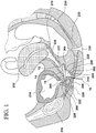
- the top surface 52 of the pressure application member 48 When deployed with the lower surface 25 of the large first ring element 26 supported upon the posterior wall 204 of the vaginal canal as shown in Figure 1 , the top surface 52 of the pressure application member 48 places a supporting force on the posterior wall 204 of the urethra 208 in a direction that is substantially perpendicular to the lumen of the urethra 208.
- This support emulates the natural support of the pelvic floor muscles which prevents unintended relief of the bladder through the urethra in normal, healthy physiological conditions.
- the positioning of the large first ring element 26 and the second member ring 54 in their fully expanded orientation is such that that they are set at a physiologically appropriate angle (34 - 44 degrees, depending on flexion capabilities) to cause the desired interior with the anterior wall and the urethra 208.
- the large first ring element 26 and the second member ring 54 in conjunction with the opening in the pelvic floor, provide the support structuring and transfer upward force for the urethral support to the first end 20 of the first member 12 at the first end 16 of the stress incontinence device 10.
- This interaction with the posterior wall 204 of the vaginal canal 202 creates the support base and force transfer for urethral support.
- the function of the stress incontinence device 10 is based on the concept that support of the pelvic floor muscles posterior to the urethra 208 in normal, healthy physiological conditions prevents unintended relief of the bladder through the urethra.
- the lower surface 24 of the first member 12 (in particular, the lower surface 25 of the large first ring 26) in contact with the posterior wall 204 of the vaginal canal 202, but the lower surface 24 of the first member 12 may be positioned in contact with the anterior wall 206 of the vaginal canal 202 as shown in Figure 1 .
- bottom surface 50 of the pressure application member 48 comes into contact with the anterior wall 206 of the vaginal canal 202 to provide support to the urethra 208 when the lower surfaces 25, 42 of both the large first ring 26 and the small second ring element 28 are also supported upon the anterior wall 206 of the vaginal canal 202.
- the stress incontinence device 10 is inserted into the vagina 200 with the large first ring element 26 and the second member ring 54 on the second end 18 of the stress incontinence device 10 entering the vagina 200 first.
- the small second ring element 28 and pressure application member 48 on the first end 16 of the stress incontinence device 10 enters the vagina 200 last.
- the pressure application member 48 of the stress incontinence device 10 then rests in the deep portion of the vagina 200.
- the lower surface 24 of the first member 12 that is, the lower surfaces 25, 42 of both the large first ring element 26 and small second ring element 28
- the second member 14 is released allowing the second member ring 54 to move outwardly away from the large first ring element 26. It is appreciated, the small second ring element 28 at the first end 16 of the stress incontinence device 10 flairs and provides positive positioning support around the opening in the pelvic floor opposite of the large first ring element 26 and the second member ring 54 to help secure the stress incontinence device 10 in place.
- the second member ring 54 moves away from the large first ring element 26 until the top surface of the second ring member 54 comes into contact with the posterior wall 204 of the vaginal canal 202, which in turn causes the pressure application member 48 at the first end 20 of the first member 12 to move toward the anterior wall 206 of the vaginal canal 202 in a manner applying pressure thereto that ultimately applies pressure to the urethra 208 for controlling incontinence.
- Cooperation between a stress incontinence device 10 positioned in the vagina 200 and the symphysis pubis 216 allows the urethra 208 to be compressed upon itself thereby providing a means to alleviate involuntary urine flow from the bladder.
- the bottom surface 50 of the pressure application member 48 places a supporting force on the posterior side of the urethra 208 in a direction that is substantially perpendicular to the lumen of the urethra 208.
- This support emulates the natural support of the pelvic floor muscles which prevents unintended relief of the bladder through the urethra 208 in normal, healthy physiological conditions.
- the large first ring element 26 and the second member ring 54 in conjunction with the opening in the pelvic floor, provide the support structuring and transfer upward force for the urethral support to the first end 20 of the first member 12 at the first end 16 of the stress incontinence device 10. This interaction with the posterior wall 204 of the vaginal canal 202 creates the support base and force transfer for urethral support.
- the function of the stress incontinence device 10 is based on the concept that support of the pelvic floor muscles posterior to the urethra 208 in normal, healthy physiological conditions prevents unintended relief of the bladder through the urethra.
- the human user may simply pull upon the removal string 15. Pulling upon the removal string 15 causes the stress incontinence device 10 to move toward the introital opening 218 and out of the vaginal canal 202.
- the first and second members 12, 14 move toward each other, that is, the second member ring 54 moves toward the large first ring element 26 an ultimately resembles the insertion state discussed above as it is finally pulled through the introital opening 218 and out of the vagina 200.
Landscapes
- Health & Medical Sciences (AREA)
- Urology & Nephrology (AREA)
- Cardiology (AREA)
- Oral & Maxillofacial Surgery (AREA)
- Transplantation (AREA)
- Engineering & Computer Science (AREA)
- Biomedical Technology (AREA)
- Heart & Thoracic Surgery (AREA)
- Vascular Medicine (AREA)
- Life Sciences & Earth Sciences (AREA)
- Animal Behavior & Ethology (AREA)
- General Health & Medical Sciences (AREA)
- Public Health (AREA)
- Veterinary Medicine (AREA)
- Prostheses (AREA)
- Orthopedics, Nursing, And Contraception (AREA)
- Massaging Devices (AREA)
Description
- The present invention generally relates to an incontinence device.
- By way of background, it is well appreciated the female pelvic region includes portions of the female reproductive system, female gastrointestinal system and the female urinary system. The female pelvic region is shown in
Figures 1 and2 , and includes avagina 200, acervix 210, auterus 212, aurethra 208, abladder 214 and asymphysis pubis 216. Thevagina 200 includes anintroital opening 218 that exits the human body and contains avaginal canal 202 extending from theintroital opening 218 to thecervix 210. Thevaginal canal 202 has a length that ranges from between about 4 to about 6 inches in most women. Thecervix 210 is the entrance to the uterus and is located between the upper aspect of thevaginal canal 202 and theuterus 212. Thevaginal canal 202 has aninner periphery 220. - The
inner periphery 220 of the vaginal canal is composed of a right lateral wall 222, a left lateral wall (not shown), ananterior wall 206, and aposterior wall 204. The four walls encompass the entire 360 degrees of theinner periphery 220. Theanterior wall 206 is located closest to theurethra 208 and theurethra 208 is located between thesymphysis pubis 216 and thevagina 200. - The
vaginal canal 202 is commonly divided into three approximately equal sections, that is, theinferior third 236, the middle third 237 and thesuperior third 238, each representing about one-third of the overall length. Each section is approximately 2 inches in length. Theinferior third 236 of thevaginal canal 202 is the most important section for alleviating female urinary incontinence because of its proximity to theurethra 208. Theinferior third 236 of thevaginal canal 202 is the location affected by placement of vaginal insert devices which alleviate conditions of female incontinence, regardless of where in thevagina 202 the bulk of the device rests after insertion. In the erect female, themiddle third 237 of thevaginal canal 202 is horizontally offset from theinferior third 236 of thevaginal canal 202 which is substantially parallel to theurethra 208. Theurethra 208 is situated between theinferior third 236 of thevaginal canal 202 and thesymphysis pubis 216, which is a bony structure situated adjacent to a front portion of the human torso and may be referred to as the bladder neck region. - The
urethra 208, also referred to as a urethral tube, is a hollow tubular structure positioned anterior to thevaginal canal 202. Theurethra 208 extends from afirst opening 226 that exits the human body to asecond opening 228 situated at the lower surface of thebladder 214. The posterior urethrovesical angle is formed where theurethra 208 enters thebladder 214. Theurethra 208 has a length of about 1.5 inches in most women. Theurethra 208 functions to discharge urine, which is temporarily stored in thebladder 214, from the human body. Theurethra 208 has a plurality ofurethral sphincter muscles 232 located along the length of its inner periphery. Theurethral sphincter muscles 232 are situated below the opening 228 and are ring like muscles that normally maintain constriction of theurethra 208 to prevent the passage of urine. The relaxation of theurethral sphincter muscles 232 by normal physiological functioning will permit urine to be voluntarily expelled from the body. - The
pubococcygeal muscle 233 originates at thesymphysis pubis 216 and extends to the inferior extent of thecoccyx 234 with a passage in the center of the muscle through which therectum 235,vagina 200 andurethra 208 pass. The posterior portion of the passage through thepubococcygeal muscle 233 normally provides support to the posterior portion of theurethra 208 through the soft tissues of therectum 235 andvagina 200 which assist in maintaining constriction of theurethra 208 to prevent the passage of urine. When diepubococcygeal muscle 233 stretches due to childbirth or generally relaxes due to the normal aging process, support to the posterior portion of theurethra 208 is reduced and unintentional flow of urine through theurethra 208 may occur, particularly when pressure is applied to thebladder 214 during a cough or other abdominal contraction. This condition is known as stress incontinence. Replacing or supplementing support to the posterior side of theurethra 208 can help to prevent the unintentional flow of urine through theurethra 208. - Numerous devices used for controlliong incontinence in females are known from the prior art.
US 2013/150661 A1 describes devices and methods for intra-vaginal bowel control.
US 5,771,899 A discloses a pessary for treating uterine prolapse and/or stress urinary incontinence.US 2010/305395 A1 describes devices for treating stress incontinence. A urinary incontinence device is disclosed byUS 6,676,594 B1 . According toWO 97/34550 A1 WO 2008/152628 A1 discloses an adjustable tension ring for amelioration of urinary incontinence in females. Finally,
WO 2015/193700 A1 discloses a vaginal ring pessary that is double folded for easy insertion by using an applicator. - It is, therefore, an object of the present invention to provide an incontinence device used to apply supporting pressure to an anterior wall of an inferior third of a vaginal canal in the approximate plane of a pubococcygeal muscle and ultimately to a urethra for controlling incontinence. The incontinence device includes a first member having a first end and second end, as well as a second member resiliendy connected to the first member. The second member is biased outwardly from the first member to direct the first end of the first member toward the anterior wall of the vaginal canal in a manner providing a support structure transferring upward force for support of the urethra by the first end of the first member.
- Preferably, the incontinence device is constructed of a flexible, biocompatible polymeric or elastomeric material.
- Preferably, the first member is shaped and dimensioned for positioning upon either a posterior wall or an anterior wall of the vaginal canal.
- Preferably, the first member is substantially flat along its upper and lower surfaces such that the upper surface lies in a first plane and the lower surface lies in a second plane that is substantially parallel to the first plane. According to the invention the first member includes a first ring element at the first end of the first member and a second ring element at the second end of the first member, wherein the first ring element and the second ring element share a segment at a junction of the first ring element and the second ring element, and the second member is constructed as a ring, wherein the second member has a diameter that is slightly smaller than that of the first ring element such that the second member fits within the first ring element of the first member when the incontinence device is compressed to a low profile deployment configuration.
- Preferably, the second member is secured to the first member at the junction of the first and second ring elements of the first member in a manner allowing the second member to pivot relative to the first member.
- Preferably, the first ring element is larger than the second ring element.
- Preferably, the second ring element of the first member is provided with a pressure application member at a position diametrically opposed to the junction of the first and the second ring elements of the first member, wherein the pressure application member is shaped and dimensioned to provide support to the urethra at the first end of the first member.
- Preferably, the pressure application member includes a wedge configuration with a bottom surface extending at an angle from a lower surface of the second ring element of the first member and a top surface extending at an angle from an upper surface of the second ring element of the first member to a tip of the wedge.
- Preferably, a pressure application member is provided at the first end of the first member, the pressure application member being shaped and dimensioned to provide support to the urethra at the first end of the first member.
- Preferably, the pressure application member is symmetrical allowing for either side thereof to provide support to the urethra.
- Preferably, the incontinence device includes a removal string attached to the incontinence device first member.
- Preferably, the removal string is attached to the first member.
- Other objects and advantages of the present invention will become apparent from the following detailed description when viewed in conjunction with the accompanying drawings, which set forth certain embodiments of the invention.
-
-
Figure 1 a cross section view of the female pelvic region with the present incontinence device inserted with the lower surface of the large first ring element facing the posterior wall of the vaginal canal. -
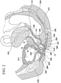
Figure 2 a cross section view of the female pelvic region with the present incontinence device inserted with the lower surface of the first member facing the anterior wall of the vaginal canal. -
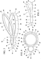
Figure 3 is a perspective view of the incontinence device. -
Figure 4 is a top plan view of the incontinence device shown inFigure 3 . -
Figure 5 is a side elevation view of the incontinence device shown inFigure 3 , which shows in broken lines the second member ring recessed within the first ring member. -
Figure 6 is a perspective view of an alternative embodiment of an incontinence device. - The detailed embodiment of the present invention is disclosed herein. It should be understood, however, that the disclosed embodiment is merely exemplary of the invention, which may be embodied in various forms. Therefore, the details disclosed herein are not to be interpreted as limiting, but merely as a basis for teaching one skilled in the art how to make and/or use the invention.
- Referring to
Figures 1 to 5 , and considering the female pelvic anatomy as described above with reference toFigures 1 and2 , the presentstress incontinence device 10 is adapted for positioning such that thefirst end 16 rests in the plane ofpubococcygeal muscle 233 with the remainder of thestress incontinence device 10 in central and superior portions ofvaginal canal 202. Thestress incontinence device 10 is positioned such that thepressure application member 48 at thefirst end 16 of the stress incontinence device can be used to apply pressure support to theanterior wall 206 of the inferior third 236 of thevaginal canal 202 in the approximate plane of thepubococcygeal muscle 233 and ultimately to theurethra 208 for controlling incontinence. As will be discussed below in greater detail, theincontinence device 10 may be positioned within the vaginal canal with either the largefirst ring element 26 of thefirst member 12 is supported upon theposterior wall 204 of thevaginal canal 202 or the largefirst ring element 26 of the first member is supported upon theanterior wall 206 of thevaginal canal 202; as such, thestress incontinence device 10 may be insert upside down. - The
incontinence device 10 is constructed of a material that is flexible in nature, such as a heavy silicone, so that thestress incontinence device 10 can collapse inside an applicator. It is further contemplated thestress incontinence device 10 may be composed of other flexible, biocompatible polymeric or elastomeric materials such as polyolefins, acetel, urethane, ABS, or various thermoplastic elastomers. - The
stress incontinence device 10 includes afirst member 12 and asecond member 14 resiliently connected in a manner providing a support structure transferring upward force for support of theurethra 208 by thefirst end 20 of thefirst member 12. Thestress incontinence device 10 includes afirst end 16 and asecond end 18. As will be appreciated based upon the following disclosure, thefirst member 12 of thestress incontinence device 10 is shaped and dimensioned for positioning upon either theposterior wall 204 or theanterior wall 206 of thevaginal canal 202, while thesecond member 14 is biased outwardly from thefirst member 12 in a manner causing contact with the opposite wall of thevaginal canal 202 to direct thefirst end 16 of thestress incontinence device 10, in particular, thefirst end 20 of thefirst member 12 toward theanterior wall 206 of thevaginal canal 202 and ultimately into contact with theurethra 208 for controlling incontinence. - The
first member 12 is substantially flat along its upper andlower surfaces upper surface 22 lies in a first plane and thelower surface 24 lies in a second plane that is substantially parallel to the first plane. With this in mind, it is appreciated thelower surfaces second ring elements lower surface 42 of the smallsecond ring element 28 sits slightly above thelower surface 25 of the largefirst ring element 26. It is appreciated relative terms such as upper, lower, top and bottom are used throughout the present disclosed, and these terms are merely used in reference to the various drawings employed in disclosing the present invention. - The
first member 12 is composed of a largefirst ring element 26 and a smallsecond ring element 28. The first andsecond ring elements stress incontinence device 10 are shaped and dimensioned to optimize support of thefirst member 12, in particular, support of the largefirst ring element 26, along theposterior wall 204 oranterior wall 206 of thevaginal canal 202 in a manner allowing the smallsecond ring element 28 at thefirst end 20 of thefirst member 12 to engage, and apply force to, theanterior wall 206 of thevaginal canal 202 for controlling incontinence. - With this in mind, the
first member 12 includes afirst end 20 at which the smallsecond ring element 28 is positioned and asecond end 30 at which the largefirst ring element 26 is positioned. The smallsecond ring element 28 and the largefirst ring element 26 are joined at ajunction 32 where the largefirst ring element 26 continues its circumference and the smallsecond ring element 28 includes a small inward section, that is, the smallsecond ring element 28 and the largefirst ring element 26 share anarcuate segment 34 at thejunction 32, wherein thearcuate segment 34 is continuous with the largefirst ring element 26. - The large
first ring element 26 includes anupper surface 22, alower surface 24, anouter side wall 36 between the upper andlower surfaces inner side wall 38 between the upper andlower surfaces second ring element 28 includes anupper surface 40, alower surface 42, anouter side wall 44 between the upper andlower surfaces inner side wall 46 between the upper andlower surfaces - The small
second ring element 28 is further provided with apressure application member 48 at a position diametrically opposed to thejunction 32 of the smallsecond ring element 28 and the largefirst ring element 26. Thepressure application member 48 is shaped and dimensioned to provide support to theurethra 208 at thefirst end 16 of thestress incontinence device 10. As such, thepressure application member 48 includes a wedge configuration with abottom surface 50 extending at an angle from thelower surface 42 of the smallsecond ring element 28 and atop surface 52 extending at an angle from theupper surface 40 of the smallsecond ring element 28 to thetip 53 of the wedge to form an isosceles triangular configuration. While a wedge shape is disclosed above for the pressure application member it is contemplated the pressure application member could be more bulbous and/or rounded. In addition to the application of pressure, the smallsecond ring element 28 acts as a secondary manual loop for removal, should string removal fail. - The
pressure application member 48, in particular, the bottom andtop surfaces top surface 52 of thepressure application member 48 when the largefirst ring element 26 is supported upon theposterior wall 204 of thevaginal canal 202 or thebottom surface 50 of thepressure application member 48 when the largefirst ring element 26 is supported upon theanterior wall 206 of the vaginal canal 202) as thepressure application member 48 is brought into contact with theanterior wall 206 of thevaginal canal 202 and applies pressure to the urethra 202 (seeFigures 1 and2 ). As such, thepressure application member 48 is substantially symmetrical. In particular, thetop surface 52 comes into contact with theanterior wall 206 of thevaginal canal 202 to provide support to theurethra 208 when the largefirst ring element 26 is supported upon theposterior wall 204 of thevaginal canal 202, and thebottom surface 50 of thepressure application member 48 comes into contact with theanterior wall 206 of thevaginal canal 202 to provide support to theurethra 208 when the largefirst ring element 26 is supported upon theanterior wall 206 of the vaginal canal 202 (seeFigures 1 and2 ). - In accordance with an alternate embodiment shown in
Figure 6 , the smallsecond ring element 28 takes a shape that is not completely circular, but rather includes an arcuate front end adjacent to the pressure application member and straightening side walls that are ultimately coupled with the large first ring element at the junction in a manner similar to the embodiment disclosed above. With this in mind, and in accordance with this embodiment, the small second ring element includes anupper surface 40, alower surface 42, anouter side wall 44 between the upper andlower surfaces inner side wall 46 between the upper andlower surfaces second ring element 28 is further provided with apressure application member 48 at a position diametrically opposed to thejunction 32 of the smallsecond ring element 28 and the largefirst ring element 26. - As with the prior embodiment, the
pressure application member 48 is shaped and dimensioned to provide support to theurethra 208 at thefirst end 16 of thestress incontinence device 10. Thepressure application member 48 includes a wedge configuration with abottom surface 50 extending at an angle from thelower surface 42 of the smallsecond ring element 28 and atop surface 52 extending at an angle from theupper surface 40 of the smallsecond ring element 28 to thetip 53 of the wedge to form an isosceles triangular configuration. In contrast to the embodiment disclosed with reference toFigures 1 to 5 , thepressure application member 48 of the this embodiment is integrated with the remainder of the smallsecond ring element 28 such that there is no distinct transition. Rather, the smallsecond ring element 28 includes a smooth exterior surface. While a wedge shape is disclosed above for the pressure application member it is contemplated the pressure application member could be more bulbous and/or rounded. - A
string removal loop 29 is also provided within the smallsecond ring element 28. Thesting removal loop 29 is shaped and dimensioned for attachment of theremoval string 15 thereto and is formed along the junction so as to extend into the interior space defined by the smallsecond ring element 28. In addition to the application of pressure, the smallsecond ring element 28 acts as a secondary manual loop for removal, shouldremoval string 15 fail. - As with the embodiment disclosed above with reference to
Figures 3 to 5 , thepressure application member 48, in particular, the bottom andtop surfaces urethra 208 as thepressure application member 48 is brought into contact with theanterior wall 206 of thevaginal canal 202 and applies pressure to theurethra 202. - The
second member 14 is also constructed as a ring. As with the first andsecond ring elements second member ring 54 includes anupper surface 56, alower surface 58, anouter side wall 60 between the upper andlower surfaces inner side wall 62 between the upper andlower surfaces second member ring 54 has a diameter that is slightly smaller than that of the largefirst ring element 26 such that thesecond member ring 54 fits within the largefirst ring element 26 when thestress incontinence device 10 is compressed to its low profile deployment configuration. Thesecond member ring 54 is secured to thefirst member 12 at thejunction 32 of the first andsecond ring elements second member ring 54 to pivot relative to thefirst member 12. Thesecond member ring 54 is aligned to pivot relative to the largefirst ring element 26 of thefirst member 12 such that thesecond member ring 54 pivots about an axis that extends transvers to thearcuate segment 34 at thejunction 32 of the largefirst ring element 26 and the smallsecond ring element 28. With this arrangement, and if one where to pivot thesecond member ring 54 about the axis it would fits within the largefirst ring element 26. This ability to recess thesecond member ring 54 within the first ring element 26provides for a substantially profile reduction and thereby assists in deployment and removal. It is appreciated that while thesecond member ring 54 is disclosed herein as being slightly smaller than the largefirst ring element 26, the sizes could be flipped, that is, thefirst ring element 26 could be made to have a smaller diameter so that it fits withinsecond member ring 54. - As mentioned above, the
stress incontinence device 10 is constructed to allow for movement of thesecond member 14, that is, thesecond member ring 54, relative to thefirst member 12, that is, the largefirst ring element 26 and the smallsecond ring element 28. The movement occurs as a result of a resilient bias created at the junction of thesecond member ring 54 and thesecond member 14 which biases thesecond member ring 54 in a direction away from the largefirst ring element 26. In accordance with a preferred embodiment, the positioning of the largefirst ring element 26 and thesecond member ring 54 in their fully expanded orientation is such that that they are set at a physiologically appropriate angle (34 - 44 degrees, depending on flexion capabilities). In particular, the bias causes the portion of thesecond member ring 54 diametrically opposed to the junction 64 of thesecond member ring 54 and thesecond member 14 to move away from the portion of the largefirst ring element 26 diametrically opposed to the junction 64 of thesecond member ring 54 and thesecond member 14 in a manner allowing the controlled expansion of thestress incontinence device 10 that forces thepressure application member 48 toward theanterior wall 206 of thevaginal canal 202 when thestress incontinence device 10 is properly positioned within thevaginal canal 202 to apply pressure to theanterior wall 206 of thevaginal canal 202 and ultimately to theurethra 208 for controlling incontinence. - In practice, the
stress incontinence device 10 is prepackaged within an inserter for deployment within thevaginal canal 202. Although not shown it is contemplated an inserter would simply be a "tubular structure" in which thestress incontinence device 10 is drawn into a pre-collapsed orientation to ease initial placement into the vagina. It would then, however, need to be "pushed out" of the tube to remain in the vagina. - While in the inserter the
second member 14 is collapsed into thefirst member 12 so as to reduce the profile of thestress incontinence device 10 and ease insertion within the vaginal canal (that is, the insertion state of the stress incontinence device 10). Thestress incontinence device 10 is then inserted within thevaginal canal 202 and positioned with the lower surface of thefirst member 12 in contact with theposterior wall 204 of thevaginal canal 202. In particular, thestress incontinence device 10 is inserted into thevagina 200 with the largefirst ring element 26 and thesecond member ring 54 on thesecond end 18 of thestress incontinence device 10 entering thevagina 200 first. The smallsecond ring element 28 andpressure application member 48 on thefirst end 16 of thestress incontinence device 10 enters thevagina 200 last. The largefirst ring element 26 and thesecond member ring 54, which compress during entry, into the vagina expand in the deep portion of thevagina 200 which, in the erect female, is above but generally parallel to the muscles in the pelvic floor. This maintains the device in thevagina 200. - The
pressure application member 48 of thestress incontinence device 10 then rests in the deep portion of thevagina 200. Thevagina 200 of the erect female bends inferiorly and in an anterior direction, passing through the muscles of the pelvic floor. The smallsecond ring element 28 andpressure application member 48 on thefirst end 16 of thestress incontinence device 10 rest in this part of thevagina 200 such that the support feature falls in the plane of the pelvic floor muscles. - Once the
stress incontinence device 10 is properly positioned within thevaginal canal 202, thesecond member 14 is releases allowing thesecond member ring 54 to move outwardly away from the largefirst ring element 26. It is appreciated, the smallsecond ring element 28 at thefirst end 16 of thestress incontinence device 10 flairs and provides positive positioning support around the opening in the pelvic floor opposite of the largefirst ring element 26 and thesecond member ring 54 to help secure thestress incontinence device 10 in place. - The movement of the
second member ring 54 away from the largefirst ring element 26 causes thepressure application member 48 at thefirst end 20 of thefirst member 12 to move into contact with theanterior wall 206 of thevaginal canal 202 in a manner applying pressure thereto that ultimately applies pressure to theurethra 208 for controlling incontinence. Cooperation between astress incontinence device 10 positioned in thevagina 200 and thesymphysis pubis 216 allows theurethra 208 to be compressed upon itself thereby providing a means to alleviate involuntary urine flow from the bladder. - When deployed with the
lower surface 25 of the largefirst ring element 26 supported upon theposterior wall 204 of the vaginal canal as shown inFigure 1 , thetop surface 52 of thepressure application member 48 places a supporting force on theposterior wall 204 of theurethra 208 in a direction that is substantially perpendicular to the lumen of theurethra 208. This support emulates the natural support of the pelvic floor muscles which prevents unintended relief of the bladder through the urethra in normal, healthy physiological conditions. - In particular, the positioning of the large
first ring element 26 and thesecond member ring 54 in their fully expanded orientation (that is, the deployed state of the stress incontinence device 10) is such that that they are set at a physiologically appropriate angle (34 - 44 degrees, depending on flexion capabilities) to cause the desired interior with the anterior wall and theurethra 208. The largefirst ring element 26 and thesecond member ring 54, in conjunction with the opening in the pelvic floor, provide the support structuring and transfer upward force for the urethral support to thefirst end 20 of thefirst member 12 at thefirst end 16 of thestress incontinence device 10. This interaction with theposterior wall 204 of thevaginal canal 202 creates the support base and force transfer for urethral support. The function of thestress incontinence device 10 is based on the concept that support of the pelvic floor muscles posterior to theurethra 208 in normal, healthy physiological conditions prevents unintended relief of the bladder through the urethra. - It is appreciated that it is not necessary to position the
lower surface 24 of the first member 12 (in particular, thelower surface 25 of the large first ring 26) in contact with theposterior wall 204 of thevaginal canal 202, but thelower surface 24 of thefirst member 12 may be positioned in contact with theanterior wall 206 of thevaginal canal 202 as shown inFigure 1 . In such an arrangement,bottom surface 50 of thepressure application member 48 comes into contact with theanterior wall 206 of thevaginal canal 202 to provide support to theurethra 208 when thelower surfaces first ring 26 and the smallsecond ring element 28 are also supported upon theanterior wall 206 of thevaginal canal 202. - In particular, and as with the previously described deployment orientation, the
stress incontinence device 10 is inserted into thevagina 200 with the largefirst ring element 26 and thesecond member ring 54 on thesecond end 18 of thestress incontinence device 10 entering thevagina 200 first. The smallsecond ring element 28 andpressure application member 48 on thefirst end 16 of thestress incontinence device 10 enters thevagina 200 last. Thepressure application member 48 of thestress incontinence device 10 then rests in the deep portion of thevagina 200. In contrast to the embodiment disclosed with reference toFigure 1 , thelower surface 24 of the first member 12 (that is, thelower surfaces first ring element 26 and small second ring element 28) faces theanterior wall 206 of thevaginal canal 202. - Once the
stress incontinence device 10 is properly positioned within thevaginal canal 202, thesecond member 14 is released allowing thesecond member ring 54 to move outwardly away from the largefirst ring element 26. It is appreciated, the smallsecond ring element 28 at thefirst end 16 of thestress incontinence device 10 flairs and provides positive positioning support around the opening in the pelvic floor opposite of the largefirst ring element 26 and thesecond member ring 54 to help secure thestress incontinence device 10 in place. Thesecond member ring 54 moves away from the largefirst ring element 26 until the top surface of thesecond ring member 54 comes into contact with theposterior wall 204 of thevaginal canal 202, which in turn causes thepressure application member 48 at thefirst end 20 of thefirst member 12 to move toward theanterior wall 206 of thevaginal canal 202 in a manner applying pressure thereto that ultimately applies pressure to theurethra 208 for controlling incontinence. Cooperation between astress incontinence device 10 positioned in thevagina 200 and thesymphysis pubis 216 allows theurethra 208 to be compressed upon itself thereby providing a means to alleviate involuntary urine flow from the bladder. Thebottom surface 50 of thepressure application member 48 places a supporting force on the posterior side of theurethra 208 in a direction that is substantially perpendicular to the lumen of theurethra 208. This support emulates the natural support of the pelvic floor muscles which prevents unintended relief of the bladder through theurethra 208 in normal, healthy physiological conditions. The largefirst ring element 26 and thesecond member ring 54, in conjunction with the opening in the pelvic floor, provide the support structuring and transfer upward force for the urethral support to thefirst end 20 of thefirst member 12 at thefirst end 16 of thestress incontinence device 10. This interaction with theposterior wall 204 of thevaginal canal 202 creates the support base and force transfer for urethral support. - Ultimately, the function of the
stress incontinence device 10 is based on the concept that support of the pelvic floor muscles posterior to theurethra 208 in normal, healthy physiological conditions prevents unintended relief of the bladder through the urethra. - When it is desired to remove the
stress incontinence device 10, the human user may simply pull upon theremoval string 15. Pulling upon theremoval string 15 causes thestress incontinence device 10 to move toward theintroital opening 218 and out of thevaginal canal 202. As a result of the shape of thevaginal canal 202 and theintroital opening 218, the first andsecond members second member ring 54 moves toward the largefirst ring element 26 an ultimately resembles the insertion state discussed above as it is finally pulled through theintroital opening 218 and out of thevagina 200. - While the preferred embodiments have been shown and described, it will be understood that there is no intent to limit the invention by such disclosure, but rather, it is intended to cover all modifications and alternate constructions falling within the scope of the appended claims.
Claims (13)
- An incontinence device (10) suitable to be used to apply supporting pressure to an anterior wall (206) of an inferior third (236) of a vaginal canal (202) in the approximate plane of a pubococcygeal muscle (233) and ultimately to a urethra (208) for controlling incontinence, comprising:a first member (12) having a first end (20) and a second end (30);a second member (14) resiliently connected to the first member (12), and the second member (14) is biased outwardly from the first member (12) to direct the first end (20) of the first member (12) toward the anterior wall (206) of the vaginal canal (202) in a manner providing a support structure configured to transfer upward force for support of the urethra (208) by the first end (20) of the first member (12); andwherein the first member (12) includes a first ring element (26) at the first end (20) of the first member (12) and a second ring element (28) at the second end (30) of the first member (12), wherein the first ring element (26) and the second ring element (28) share a segment (34) at a junction (32) of the first ring element (26) and the second ring element (28),wherein the second member (14) is constructed as a ring (54),characterized in thatthe second member (14) has a diameter that is slightly smaller than that of the first ring element (26) such that the second member (14) fits within the first ring element (26) of the first member (12) when the incontinence device (10) is compressed to a low profile deployment configuration.
- The incontinence device (10) according to claim 1, wherein the incontinence device (10) is constructed of a flexible, biocompatible polymeric or elastomeric material.
- The incontinence device (10) according to claim 1, wherein the first member (12) is shaped and dimensioned for positioning upon either the posterior wall or the anterior wall (206) of the vaginal canal (202).
- The incontinence device (10) according to claim 1, wherein the first member (12) is substantially flat along its upper and lower surfaces such that the upper surface lies in a first plane and the lower surface lies in a second plane that is substantially parallel to the first plane.
- The incontinence device (10) according to claim 1, wherein the second member (14) is secured to the first member (12) at the junction (32) of the first and second ring elements (26, 28) of the first member (12) in a manner allowing the second member (14) to pivot relative to the first member (12).
- The incontinence device (10) according to claim 1, wherein the second member (14) is secured to the first member (12) at the junction (32) of the first and second ring elements (26, 28) of the first member (12) in a manner allowing the second member (14) to pivot relative to the first member.
- The incontinence device (10) according to claim 1, wherein the first ring element (26) is larger than the second ring element (28).
- The incontinence device (10) according to claim 1, wherein the second ring element (28) of the first member (12) is provided with a pressure application member (48) at a position diametrically opposed to the junction (32) of the first and the second ring elements (26, 28) of the first member (12), wherein the pressure application member (48) is shaped and dimensioned to provide support to the urethra (208) at the first end (20) of the first member (12).
- The incontinence device (10) according to claim 8 wherein the pressure application member (48) includes a wedge configuration with a bottom surface extending at an angle from a lower surface of the second ring element (28) of the first member (12) and a top surface extending at an angle from an upper surface of the second ring element (28) of the first member (12) to a tip of the wedge.
- The incontinence device (10) according to claim 1, wherein a pressure application member (48) is provided at the first end (20) of the first member, the pressure application member (48) being shaped and dimensioned to provide support to the urethra (208) at the first end (20) of the first member.
- The incontinence device (10) according to claim 10, wherein the pressure application member (48) is symmetrical so as to allow for either side thereof to provide support to the urethra.
- The incontinence device (10) according to claim 10, wherein the pressure application member (48) includes a wedge configuration with a bottom surface (50) extending at an angle from a lower surface (42) of the second ring element (28) of the first member (12) and a top surface (52) extending at an angle from an upper surface (40) of the second ring element (28) of the first member (12) to a tip (53) of the wedge.
- The incontinence device (10) according to claim 1, further including a removal string (15) attached to the incontinence device (10) first member (12).
Applications Claiming Priority (2)
| Application Number | Priority Date | Filing Date | Title |
|---|---|---|---|
| US201662366471P | 2016-07-25 | 2016-07-25 | |
| PCT/US2017/043476 WO2018022492A1 (en) | 2016-07-25 | 2017-07-24 | Incontinence device |
Publications (3)
| Publication Number | Publication Date |
|---|---|
| EP3487449A1 EP3487449A1 (en) | 2019-05-29 |
| EP3487449A4 EP3487449A4 (en) | 2020-04-08 |
| EP3487449B1 true EP3487449B1 (en) | 2020-10-28 |
Family
ID=60989696
Family Applications (1)
| Application Number | Title | Priority Date | Filing Date |
|---|---|---|---|
| EP17835048.4A Active EP3487449B1 (en) | 2016-07-25 | 2017-07-24 | Incontinence device |
Country Status (7)
| Country | Link |
|---|---|
| US (2) | US10441402B2 (en) |
| EP (1) | EP3487449B1 (en) |
| CN (1) | CN109475401B (en) |
| AU (2) | AU2017302514B2 (en) |
| BR (1) | BR112019001393B1 (en) |
| ES (1) | ES2842674T3 (en) |
| WO (1) | WO2018022492A1 (en) |
Families Citing this family (16)
| Publication number | Priority date | Publication date | Assignee | Title |
|---|---|---|---|---|
| US20150112231A1 (en) | 2011-11-28 | 2015-04-23 | Remendium Labs Llc | Treatment of fecal incontinence |
| US20150112230A1 (en) | 2011-11-28 | 2015-04-23 | Remendium Labs Llc | Treatment of male urinary incontinence and sexual dysfunction |
| CA2936061A1 (en) | 2014-01-06 | 2015-07-09 | Remendium Labs Llc | System and method for kegel training |
| KR102589133B1 (en) | 2016-07-29 | 2023-10-12 | 레노비아 인크. | Devices, systems, and methods for training pelvic floor muscles |
| USD832437S1 (en) * | 2017-07-24 | 2018-10-30 | Rinovum Subsidiary 2, LLC | Incontinence device |
| USD833009S1 (en) * | 2017-07-24 | 2018-11-06 | Rinovum Subsidiary 2, LLC | Incontinence device |
| EP4628016A3 (en) | 2017-10-27 | 2025-12-17 | Axena Health, Inc. | Devices, systems, and methods for training pelvic floor muscles |
| US12138019B2 (en) | 2018-04-13 | 2024-11-12 | Axena Health, Inc. | Devices, systems, and methods for training pelvic floor muscles |
| WO2019210204A1 (en) | 2018-04-27 | 2019-10-31 | Renovia Inc. | Devices, systems, and methods for treating urinary and fecal incontinence |
| JP2022506203A (en) | 2018-10-30 | 2022-01-17 | レノビア インコーポレイテッド | Devices, systems, and methods for monitoring bladder function |
| USD898911S1 (en) | 2019-04-03 | 2020-10-13 | Renovia Inc. | Intravaginal device assembly |
| USD896958S1 (en) * | 2019-04-11 | 2020-09-22 | Renovia Inc. | Intravaginal device |
| USD899593S1 (en) * | 2019-04-12 | 2020-10-20 | Renovia Inc. | Intravaginal device |
| USD896959S1 (en) * | 2019-04-23 | 2020-09-22 | Renovia Inc. | Intravaginal device |
| USD897530S1 (en) * | 2019-04-23 | 2020-09-29 | Renovia Inc. | Intravaginal device |
| WO2025159727A1 (en) * | 2024-01-22 | 2025-07-31 | Sultanov Serhii Anatoliiovych | Volumetric cross pessary |
Family Cites Families (85)
| Publication number | Priority date | Publication date | Assignee | Title |
|---|---|---|---|---|
| US2574767A (en) * | 1950-04-14 | 1951-11-13 | Stubbs George | Pessary |
| US3196873A (en) | 1962-08-27 | 1965-07-27 | Kimberly Clark Co | Tampon and applicator |
| US4536178A (en) | 1983-11-10 | 1985-08-20 | International Playtex, Inc. | Tampon applicator |
| US4726805A (en) | 1986-06-26 | 1988-02-23 | Tambrands Inc. | Tampon applicator |
| EP0264258B1 (en) | 1986-10-14 | 1992-04-22 | Zedlani Pty. Limited | Urinary incontinence device |
| US5386836A (en) * | 1986-10-14 | 1995-02-07 | Zedlani Pty Limited | Urinary incontinence device |
| US4846819A (en) * | 1987-02-24 | 1989-07-11 | Sherwood Medical Company | Female incontinence device having improved rim structure |
| US5007894A (en) * | 1989-02-10 | 1991-04-16 | Goran Enhorning | Female incontinence device |
| US5256133A (en) | 1990-09-05 | 1993-10-26 | Spitz Robert M | Device for correcting stress urinary incontinence |
| US5437628A (en) | 1993-11-10 | 1995-08-01 | Kimberly-Clark Corporation | Curved tampon applicator having an improved fingergrip |
| US5671755A (en) | 1994-06-29 | 1997-09-30 | Uromed Corporation | Assembly and method for controlling urinary incontinence in humans |
| US5771899A (en) * | 1996-03-14 | 1998-06-30 | Bioteque America Inc. | Pessary |
| AUPN881596A0 (en) * | 1996-03-20 | 1996-04-18 | Biswas, Nicholas | An intra-vaginal device |
| US5785640A (en) | 1996-05-23 | 1998-07-28 | Kresch; Arnold J. | Method for treating female incontinence |
| EP0923357B1 (en) | 1997-03-20 | 2005-07-13 | Niquoola Pty. Ltd. | An intra-vaginal device |
| US6158435A (en) * | 1998-09-14 | 2000-12-12 | Dorsey; Denis P. | Pessary |
| US6142928A (en) | 1998-12-21 | 2000-11-07 | Kimberly-Clark Worldwide, Inc. | Urinary incontinence device and a method of making the same |
| US6090098A (en) | 1998-12-21 | 2000-07-18 | Kimberly-Clark Worldwide, Inc. | Method for alleviating female urinary incontinence |
| US6645136B1 (en) | 2000-09-28 | 2003-11-11 | Kimberly-Clark Worldwide, Inc. | Incontinence insert applicators and methods for their use |
| US6503190B1 (en) | 2000-09-29 | 2003-01-07 | Ethicon Endo-Surgery, Inc. | Vaginal pessary |
| US6418930B1 (en) | 2000-11-14 | 2002-07-16 | Mayo Foundation For Medical Education And Research | Anatomic incontinence pessary |
| US6460542B1 (en) * | 2001-01-03 | 2002-10-08 | Medical Technology & Innovations, Inc. | Female incontinence control device |
| US6652477B2 (en) | 2001-08-06 | 2003-11-25 | The Procter & Gamble Company | Tampon applicator with petals |
| IL146534A (en) * | 2001-11-15 | 2007-06-17 | Gynotech Ltd | Adjustable vaginal pessary |
| US6695763B2 (en) | 2002-01-02 | 2004-02-24 | Kimberly-Clark Worldwide, Inc. | Incontinence insert device and method of using same |
| CA2371974C (en) * | 2002-02-15 | 2003-05-13 | Farrell Medical Incorporated | Incontinence inhibiting or prevention device |
| US6676594B1 (en) * | 2002-09-18 | 2004-01-13 | Kimberly-Clark Worldwide, Inc. | C-shaped vaginal incontinence insert |
| US6939289B2 (en) | 2002-10-21 | 2005-09-06 | Kimberly-Clark Worldwide, Inc. | Ellipitcal applicator system |
| US7263999B2 (en) * | 2002-10-30 | 2007-09-04 | Kabushiki Kaisha Kitazato Supply | Ring for preventing prolapse of uterus and urinary bladder and ring for preventing prolapse of uterus and rectum |
| US6808485B2 (en) | 2002-12-23 | 2004-10-26 | Kimberly-Clark Worldwide, Inc. | Compressible resilient incontinence insert |
| US7771344B2 (en) | 2003-05-22 | 2010-08-10 | Contipi Ltd. | Device for the prevention of urinary incontinence in females |
| BRPI0416638A (en) | 2003-11-17 | 2007-01-16 | Prolapse Inc | devices for implantation into a pelvis and for treatment of a pelvic organ prolapse, implantable suture-free device for supporting a pelvic organ, and method for treating prolapse of a pelvic organ |
| US7001317B2 (en) | 2003-11-24 | 2006-02-21 | Jean-Claude Marcotte | Kegel muscle exercising device and method for exercising Kegel muscle |
| EP1734892B1 (en) | 2004-03-18 | 2011-03-02 | Contipi Ltd. | Apparatus for the treatment of feminine pelvic organ prolapse |
| MX345807B (en) | 2005-03-17 | 2017-02-15 | Kimberly-Clark Worldwide Inc * | Apparatuses for the amelioration of urinary incontinence in females. |
| FR2890554B1 (en) * | 2005-09-14 | 2009-03-06 | Braun Medical Sas Soc Par Acti | DEVICE AND METHOD FOR PREVENTING FEMALE URINARY INCONTINENCE IN THE EFFORT |
| IL176883A (en) | 2005-09-22 | 2013-09-30 | Eliahu Eliachar | Apparatus for the amelioration of urinary incontinence in females |
| US7628156B2 (en) | 2005-10-25 | 2009-12-08 | Ethicon Inc. | Adjustable vaginal splint for pelvic floor support |
| US7942806B2 (en) | 2005-12-29 | 2011-05-17 | Ethicon, Inc. | Stress urinary incontinence implant and device for deploying same |
| US8613698B2 (en) | 2006-07-10 | 2013-12-24 | Mcneil-Ppc, Inc. | Resilient device |
| US8177706B2 (en) | 2006-07-10 | 2012-05-15 | Mcneil-Ppc, Inc. | Method of treating urinary incontinence |
| CN104257450B (en) | 2006-07-10 | 2017-05-10 | 第一次质量卫生公司 | Resilient Device |
| WO2008079271A1 (en) | 2006-12-21 | 2008-07-03 | Baystate Health, Inc. | Vaginal pessary |
| US9198748B2 (en) | 2007-06-11 | 2015-12-01 | Contipi Medical Ltd. | Adjustable tension ring for amelioration of urinary incontinence in females |
| WO2009044394A2 (en) | 2007-10-01 | 2009-04-09 | Contipi Ltd. | Management of urinary incontinence in females |
| US8221374B2 (en) | 2008-03-31 | 2012-07-17 | Mcneil-Ppc, Inc. | Urinary incontinence device applicator |
| US7935098B2 (en) | 2008-03-31 | 2011-05-03 | Mcneil-Ppc, Inc. | Applicator for intravaginal devices |
| US9398984B2 (en) | 2008-03-31 | 2016-07-26 | First Quality Hygienie, Inc. | Adjustable applicator for urinary incontinence devices |
| US8651109B2 (en) | 2008-04-23 | 2014-02-18 | Contipi Ltd. | Pessaries for prolapse alleviation |
| US8300783B2 (en) | 2009-02-09 | 2012-10-30 | Applied Minds, Llc | Method and apparatus for establishing data link based on audio connection |
| CA2763361C (en) * | 2009-05-28 | 2018-05-01 | Contine Corporation | Correction of stress urinary incontinence |
| US20110105830A1 (en) | 2009-10-30 | 2011-05-05 | Mari Hou | Applicator for Self-Expanding Intravaginal Urinary Incontinence Devices |
| EP2503957B1 (en) | 2009-11-24 | 2017-03-15 | Kimberly-Clark Worldwide, Inc. | Apparatuses for the treatment of urinary stress and urge incontinence |
| US8652026B2 (en) | 2009-12-31 | 2014-02-18 | Kimberly-Clark Worldwide, Inc. | Disposable urine incontinence device |
| US9289278B2 (en) * | 2010-03-16 | 2016-03-22 | Pelvalon, Inc. | Intra-vaginal devices and methods for treating fecal incontinence |
| US9072578B2 (en) * | 2010-03-16 | 2015-07-07 | Pelvalon, Inc. | Intra-vaginal device for fecal incontinence |
| US10039666B2 (en) | 2010-10-13 | 2018-08-07 | Contipi Medical Ltd. | Apparatuses and methods of intravaginal support and/or distension |
| US20120136199A1 (en) | 2010-11-30 | 2012-05-31 | Mari Hou | Cushioned Resilient Intravaginal Urinary Incontinence Device |
| US9814630B2 (en) * | 2010-12-23 | 2017-11-14 | Kimberly-Clark Worldwide, Inc. | Vaginal insert device having a support portion with plurality of foldable areas |
| US9022919B2 (en) | 2010-12-23 | 2015-05-05 | Kimberly-Clark Worldwide, Inc. | Vaginal insert device having a support portion with plurality of struts |
| US20120259167A1 (en) | 2011-04-11 | 2012-10-11 | Nancy Karapasha | Single use pessary devices |
| US20120259166A1 (en) | 2011-04-11 | 2012-10-11 | Nancy Karapasha | Array of pessary devices |
| US20120259160A1 (en) | 2011-04-11 | 2012-10-11 | Nancy Karapasha | Pessary device having improved comfort |
| US20120259164A1 (en) | 2011-04-11 | 2012-10-11 | Nancy Karapasha | Pessary device |
| CN103717173B (en) | 2011-07-29 | 2016-06-08 | 奥齿泰有限责任公司 | For the film of alveolar bone regeneration |
| EP2747703B1 (en) * | 2011-10-04 | 2017-07-19 | Gynamics Women's Health Ltd. | Female urinary incontinence device |
| US8911344B2 (en) | 2011-12-20 | 2014-12-16 | Kimberly-Clark Worldwide, Inc. | Vaginal insert device having perpendicular segments |
| EP2644150B1 (en) | 2012-03-28 | 2019-01-23 | Orthoarm, Inc. | Active self-ligating bracket |
| US9095744B2 (en) * | 2012-06-04 | 2015-08-04 | Caryn M. Horsley | Medical exercise device |
| US9320640B2 (en) | 2012-06-29 | 2016-04-26 | The Procter & Gamble Company | Method of attaching a withdrawal member to a pessary device |
| US9597222B2 (en) | 2012-10-10 | 2017-03-21 | The Procter & Gamble Company | Intra-vaginal device withdrawal assembly |
| US9439748B2 (en) * | 2012-10-10 | 2016-09-13 | The Procter & Gamble Company | Pessary device |
| US9339364B2 (en) | 2012-10-10 | 2016-05-17 | The Procter & Gamble Company | Intravaginal device withdrawal assembly |
| WO2014127270A1 (en) * | 2013-02-14 | 2014-08-21 | Pelvalon, Inc. | Intra-vaginal devices and methods for treating fecal incontinence |
| US20160235583A1 (en) | 2013-02-21 | 2016-08-18 | The Procter & Gamble Company | Intravaginal device withdrawal assembly |
| US20150297392A1 (en) | 2014-04-16 | 2015-10-22 | The Procter & Gamble Company | Pessary device and applicator having improved insertion |
| US10350042B2 (en) | 2014-04-25 | 2019-07-16 | Kimberly-Clark Worldwide, Inc. | Vaginal insert |
| WO2015193700A1 (en) * | 2014-06-17 | 2015-12-23 | Tang John Ing Ching | Double folded ring pessary and applicator |
| US10098720B2 (en) * | 2015-03-23 | 2018-10-16 | City Of Hope | Artificial urinary sphincter device |
| US10111786B2 (en) | 2015-04-10 | 2018-10-30 | First Quality Hygienic, Inc. | Tampon applicator including beveled portion |
| US20160296380A1 (en) | 2015-04-10 | 2016-10-13 | First Quality Hygienic, Inc. | Tampon applicator |
| US10201411B2 (en) | 2015-06-29 | 2019-02-12 | The Procter & Gamble Company | Pessary with applicator |
| US20170014217A1 (en) | 2015-07-16 | 2017-01-19 | Karen L. Patrusky | Intravaginal incontinence device |
| US11376155B2 (en) | 2015-10-13 | 2022-07-05 | Contipi Medical Ltd. | Devices and methods for pelvic organ prolapse alleviation |
| AU2017395751B2 (en) * | 2017-01-24 | 2023-11-02 | Liv Labs Inc. | Stress urinary incontinence (SUI) device |
-
2017
- 2017-07-24 BR BR112019001393-8A patent/BR112019001393B1/en active IP Right Grant
- 2017-07-24 ES ES17835048T patent/ES2842674T3/en active Active
- 2017-07-24 EP EP17835048.4A patent/EP3487449B1/en active Active
- 2017-07-24 AU AU2017302514A patent/AU2017302514B2/en active Active
- 2017-07-24 WO PCT/US2017/043476 patent/WO2018022492A1/en not_active Ceased
- 2017-07-24 US US15/657,581 patent/US10441402B2/en active Active
- 2017-07-24 CN CN201780046192.1A patent/CN109475401B/en active Active
-
2019
- 2019-08-19 US US16/544,627 patent/US11135047B2/en active Active
-
2022
- 2022-03-09 AU AU2022201640A patent/AU2022201640B2/en active Active
Non-Patent Citations (1)
| Title |
|---|
| None * |
Also Published As
| Publication number | Publication date |
|---|---|
| US11135047B2 (en) | 2021-10-05 |
| US10441402B2 (en) | 2019-10-15 |
| CN109475401A (en) | 2019-03-15 |
| EP3487449A4 (en) | 2020-04-08 |
| US20190365519A1 (en) | 2019-12-05 |
| BR112019001393A2 (en) | 2019-04-30 |
| AU2017302514B2 (en) | 2022-05-19 |
| AU2022201640B2 (en) | 2023-09-14 |
| EP3487449A1 (en) | 2019-05-29 |
| ES2842674T3 (en) | 2021-07-14 |
| CN109475401B (en) | 2021-10-08 |
| BR112019001393B1 (en) | 2023-04-25 |
| AU2022201640A1 (en) | 2022-03-31 |
| WO2018022492A1 (en) | 2018-02-01 |
| AU2017302514A1 (en) | 2019-03-07 |
| US20180021121A1 (en) | 2018-01-25 |
Similar Documents
| Publication | Publication Date | Title |
|---|---|---|
| AU2022201640B2 (en) | Incontinence Device | |
| US8127768B2 (en) | Apparatus for the treatment of feminine pelvic organ prolapse | |
| EP3487428B1 (en) | Incontinence device | |
| EP1545386B1 (en) | Molar shaped vaginal incontinence insert | |
| US6676594B1 (en) | C-shaped vaginal incontinence insert | |
| US9072578B2 (en) | Intra-vaginal device for fecal incontinence | |
| HK40005910A (en) | Incontinence device | |
| HK40005910B (en) | Incontinence device | |
| RU2380064C2 (en) | Device for urinary incontinence prevention in women | |
| EP4248910B1 (en) | Prolapse corrective device | |
| HK40005911B (en) | Incontinence device | |
| HK40005911A (en) | Incontinence device | |
| WO2025151970A1 (en) | Gynecological pessaries | |
| AU2011227265B2 (en) | Intra-vaginal device for fecal incontinence |
Legal Events
| Date | Code | Title | Description |
|---|---|---|---|
| STAA | Information on the status of an ep patent application or granted ep patent |
Free format text: STATUS: THE INTERNATIONAL PUBLICATION HAS BEEN MADE |
|
| PUAI | Public reference made under article 153(3) epc to a published international application that has entered the european phase |
Free format text: ORIGINAL CODE: 0009012 |
|
| STAA | Information on the status of an ep patent application or granted ep patent |
Free format text: STATUS: REQUEST FOR EXAMINATION WAS MADE |
|
| 17P | Request for examination filed |
Effective date: 20190225 |
|
| AK | Designated contracting states |
Kind code of ref document: A1 Designated state(s): AL AT BE BG CH CY CZ DE DK EE ES FI FR GB GR HR HU IE IS IT LI LT LU LV MC MK MT NL NO PL PT RO RS SE SI SK SM TR |
|
| AX | Request for extension of the european patent |
Extension state: BA ME |
|
| DAV | Request for validation of the european patent (deleted) | ||
| DAX | Request for extension of the european patent (deleted) | ||
| REG | Reference to a national code |
Ref country code: DE Ref legal event code: R079 Ref document number: 602017026552 Country of ref document: DE Free format text: PREVIOUS MAIN CLASS: A61F0002040000 Ipc: A61F0002000000 |
|
| A4 | Supplementary search report drawn up and despatched |
Effective date: 20200309 |
|
| RIC1 | Information provided on ipc code assigned before grant |
Ipc: A61F 2/00 20060101AFI20200303BHEP |
|
| GRAP | Despatch of communication of intention to grant a patent |
Free format text: ORIGINAL CODE: EPIDOSNIGR1 |
|
| STAA | Information on the status of an ep patent application or granted ep patent |
Free format text: STATUS: GRANT OF PATENT IS INTENDED |
|
| INTG | Intention to grant announced |
Effective date: 20200604 |
|
| GRAS | Grant fee paid |
Free format text: ORIGINAL CODE: EPIDOSNIGR3 |
|
| GRAA | (expected) grant |
Free format text: ORIGINAL CODE: 0009210 |
|
| STAA | Information on the status of an ep patent application or granted ep patent |
Free format text: STATUS: THE PATENT HAS BEEN GRANTED |
|
| AK | Designated contracting states |
Kind code of ref document: B1 Designated state(s): AL AT BE BG CH CY CZ DE DK EE ES FI FR GB GR HR HU IE IS IT LI LT LU LV MC MK MT NL NO PL PT RO RS SE SI SK SM TR |
|
| REG | Reference to a national code |
Ref country code: GB Ref legal event code: FG4D |
|
| REG | Reference to a national code |
Ref country code: CH Ref legal event code: EP |
|
| REG | Reference to a national code |
Ref country code: DE Ref legal event code: R096 Ref document number: 602017026552 Country of ref document: DE |
|
| REG | Reference to a national code |
Ref country code: AT Ref legal event code: REF Ref document number: 1327419 Country of ref document: AT Kind code of ref document: T Effective date: 20201115 |
|
| REG | Reference to a national code |
Ref country code: IE Ref legal event code: FG4D |
|
| REG | Reference to a national code |
Ref country code: DE Ref legal event code: R081 Ref document number: 602017026552 Country of ref document: DE Owner name: OVALA, INC., MONROEVILLE, US Free format text: FORMER OWNER: RINOVUM SUBSIDIARY 2, LLC, MONROEVILLE, PA, US |
|
| RAP2 | Party data changed (patent owner data changed or rights of a patent transferred) |
Owner name: OVALA, INC. |
|
| REG | Reference to a national code |
Ref country code: SE Ref legal event code: TRGR |
|
| REG | Reference to a national code |
Ref country code: NO Ref legal event code: T2 Effective date: 20201028 |
|
| REG | Reference to a national code |
Ref country code: AT Ref legal event code: MK05 Ref document number: 1327419 Country of ref document: AT Kind code of ref document: T Effective date: 20201028 |
|
| REG | Reference to a national code |
Ref country code: NL Ref legal event code: MP Effective date: 20201028 |
|
| PG25 | Lapsed in a contracting state [announced via postgrant information from national office to epo] |
Ref country code: GR Free format text: LAPSE BECAUSE OF FAILURE TO SUBMIT A TRANSLATION OF THE DESCRIPTION OR TO PAY THE FEE WITHIN THE PRESCRIBED TIME-LIMIT Effective date: 20210129 Ref country code: RS Free format text: LAPSE BECAUSE OF FAILURE TO SUBMIT A TRANSLATION OF THE DESCRIPTION OR TO PAY THE FEE WITHIN THE PRESCRIBED TIME-LIMIT Effective date: 20201028 Ref country code: PT Free format text: LAPSE BECAUSE OF FAILURE TO SUBMIT A TRANSLATION OF THE DESCRIPTION OR TO PAY THE FEE WITHIN THE PRESCRIBED TIME-LIMIT Effective date: 20210301 Ref country code: FI Free format text: LAPSE BECAUSE OF FAILURE TO SUBMIT A TRANSLATION OF THE DESCRIPTION OR TO PAY THE FEE WITHIN THE PRESCRIBED TIME-LIMIT Effective date: 20201028 |
|
| REG | Reference to a national code |
Ref country code: LT Ref legal event code: MG4D |
|
| PG25 | Lapsed in a contracting state [announced via postgrant information from national office to epo] |
Ref country code: LV Free format text: LAPSE BECAUSE OF FAILURE TO SUBMIT A TRANSLATION OF THE DESCRIPTION OR TO PAY THE FEE WITHIN THE PRESCRIBED TIME-LIMIT Effective date: 20201028 Ref country code: IS Free format text: LAPSE BECAUSE OF FAILURE TO SUBMIT A TRANSLATION OF THE DESCRIPTION OR TO PAY THE FEE WITHIN THE PRESCRIBED TIME-LIMIT Effective date: 20210228 Ref country code: PL Free format text: LAPSE BECAUSE OF FAILURE TO SUBMIT A TRANSLATION OF THE DESCRIPTION OR TO PAY THE FEE WITHIN THE PRESCRIBED TIME-LIMIT Effective date: 20201028 Ref country code: BG Free format text: LAPSE BECAUSE OF FAILURE TO SUBMIT A TRANSLATION OF THE DESCRIPTION OR TO PAY THE FEE WITHIN THE PRESCRIBED TIME-LIMIT Effective date: 20210128 Ref country code: AT Free format text: LAPSE BECAUSE OF FAILURE TO SUBMIT A TRANSLATION OF THE DESCRIPTION OR TO PAY THE FEE WITHIN THE PRESCRIBED TIME-LIMIT Effective date: 20201028 |
|
| PG25 | Lapsed in a contracting state [announced via postgrant information from national office to epo] |
Ref country code: HR Free format text: LAPSE BECAUSE OF FAILURE TO SUBMIT A TRANSLATION OF THE DESCRIPTION OR TO PAY THE FEE WITHIN THE PRESCRIBED TIME-LIMIT Effective date: 20201028 Ref country code: NL Free format text: LAPSE BECAUSE OF FAILURE TO SUBMIT A TRANSLATION OF THE DESCRIPTION OR TO PAY THE FEE WITHIN THE PRESCRIBED TIME-LIMIT Effective date: 20201028 |
|
| REG | Reference to a national code |
Ref country code: ES Ref legal event code: FG2A Ref document number: 2842674 Country of ref document: ES Kind code of ref document: T3 Effective date: 20210714 |
|
| REG | Reference to a national code |
Ref country code: DE Ref legal event code: R097 Ref document number: 602017026552 Country of ref document: DE |
|
| PG25 | Lapsed in a contracting state [announced via postgrant information from national office to epo] |
Ref country code: SM Free format text: LAPSE BECAUSE OF FAILURE TO SUBMIT A TRANSLATION OF THE DESCRIPTION OR TO PAY THE FEE WITHIN THE PRESCRIBED TIME-LIMIT Effective date: 20201028 Ref country code: EE Free format text: LAPSE BECAUSE OF FAILURE TO SUBMIT A TRANSLATION OF THE DESCRIPTION OR TO PAY THE FEE WITHIN THE PRESCRIBED TIME-LIMIT Effective date: 20201028 Ref country code: CZ Free format text: LAPSE BECAUSE OF FAILURE TO SUBMIT A TRANSLATION OF THE DESCRIPTION OR TO PAY THE FEE WITHIN THE PRESCRIBED TIME-LIMIT Effective date: 20201028 Ref country code: LT Free format text: LAPSE BECAUSE OF FAILURE TO SUBMIT A TRANSLATION OF THE DESCRIPTION OR TO PAY THE FEE WITHIN THE PRESCRIBED TIME-LIMIT Effective date: 20201028 Ref country code: RO Free format text: LAPSE BECAUSE OF FAILURE TO SUBMIT A TRANSLATION OF THE DESCRIPTION OR TO PAY THE FEE WITHIN THE PRESCRIBED TIME-LIMIT Effective date: 20201028 Ref country code: SK Free format text: LAPSE BECAUSE OF FAILURE TO SUBMIT A TRANSLATION OF THE DESCRIPTION OR TO PAY THE FEE WITHIN THE PRESCRIBED TIME-LIMIT Effective date: 20201028 |
|
| PG25 | Lapsed in a contracting state [announced via postgrant information from national office to epo] |
Ref country code: DK Free format text: LAPSE BECAUSE OF FAILURE TO SUBMIT A TRANSLATION OF THE DESCRIPTION OR TO PAY THE FEE WITHIN THE PRESCRIBED TIME-LIMIT Effective date: 20201028 |
|
| PLBE | No opposition filed within time limit |
Free format text: ORIGINAL CODE: 0009261 |
|
| STAA | Information on the status of an ep patent application or granted ep patent |
Free format text: STATUS: NO OPPOSITION FILED WITHIN TIME LIMIT |
|
| 26N | No opposition filed |
Effective date: 20210729 |
|
| PG25 | Lapsed in a contracting state [announced via postgrant information from national office to epo] |
Ref country code: AL Free format text: LAPSE BECAUSE OF FAILURE TO SUBMIT A TRANSLATION OF THE DESCRIPTION OR TO PAY THE FEE WITHIN THE PRESCRIBED TIME-LIMIT Effective date: 20201028 |
|
| PG25 | Lapsed in a contracting state [announced via postgrant information from national office to epo] |
Ref country code: SI Free format text: LAPSE BECAUSE OF FAILURE TO SUBMIT A TRANSLATION OF THE DESCRIPTION OR TO PAY THE FEE WITHIN THE PRESCRIBED TIME-LIMIT Effective date: 20201028 |
|
| REG | Reference to a national code |
Ref country code: CH Ref legal event code: PL |
|
| PG25 | Lapsed in a contracting state [announced via postgrant information from national office to epo] |
Ref country code: MC Free format text: LAPSE BECAUSE OF FAILURE TO SUBMIT A TRANSLATION OF THE DESCRIPTION OR TO PAY THE FEE WITHIN THE PRESCRIBED TIME-LIMIT Effective date: 20201028 |
|
| REG | Reference to a national code |
Ref country code: BE Ref legal event code: MM Effective date: 20210731 |
|
| PG25 | Lapsed in a contracting state [announced via postgrant information from national office to epo] |
Ref country code: LI Free format text: LAPSE BECAUSE OF NON-PAYMENT OF DUE FEES Effective date: 20210731 Ref country code: CH Free format text: LAPSE BECAUSE OF NON-PAYMENT OF DUE FEES Effective date: 20210731 |
|
| PG25 | Lapsed in a contracting state [announced via postgrant information from national office to epo] |
Ref country code: IS Free format text: LAPSE BECAUSE OF FAILURE TO SUBMIT A TRANSLATION OF THE DESCRIPTION OR TO PAY THE FEE WITHIN THE PRESCRIBED TIME-LIMIT Effective date: 20210228 Ref country code: LU Free format text: LAPSE BECAUSE OF NON-PAYMENT OF DUE FEES Effective date: 20210724 |
|
| PG25 | Lapsed in a contracting state [announced via postgrant information from national office to epo] |
Ref country code: BE Free format text: LAPSE BECAUSE OF NON-PAYMENT OF DUE FEES Effective date: 20210731 |
|
| P01 | Opt-out of the competence of the unified patent court (upc) registered |
Effective date: 20230514 |
|
| PG25 | Lapsed in a contracting state [announced via postgrant information from national office to epo] |
Ref country code: CY Free format text: LAPSE BECAUSE OF FAILURE TO SUBMIT A TRANSLATION OF THE DESCRIPTION OR TO PAY THE FEE WITHIN THE PRESCRIBED TIME-LIMIT Effective date: 20201028 |
|
| PG25 | Lapsed in a contracting state [announced via postgrant information from national office to epo] |
Ref country code: HU Free format text: LAPSE BECAUSE OF FAILURE TO SUBMIT A TRANSLATION OF THE DESCRIPTION OR TO PAY THE FEE WITHIN THE PRESCRIBED TIME-LIMIT; INVALID AB INITIO Effective date: 20170724 |
|
| PG25 | Lapsed in a contracting state [announced via postgrant information from national office to epo] |
Ref country code: MK Free format text: LAPSE BECAUSE OF FAILURE TO SUBMIT A TRANSLATION OF THE DESCRIPTION OR TO PAY THE FEE WITHIN THE PRESCRIBED TIME-LIMIT Effective date: 20201028 |
|
| PG25 | Lapsed in a contracting state [announced via postgrant information from national office to epo] |
Ref country code: MT Free format text: LAPSE BECAUSE OF FAILURE TO SUBMIT A TRANSLATION OF THE DESCRIPTION OR TO PAY THE FEE WITHIN THE PRESCRIBED TIME-LIMIT Effective date: 20201028 |
|
| PGFP | Annual fee paid to national office [announced via postgrant information from national office to epo] |
Ref country code: ES Payment date: 20250826 Year of fee payment: 9 |
|
| PGFP | Annual fee paid to national office [announced via postgrant information from national office to epo] |
Ref country code: DE Payment date: 20250731 Year of fee payment: 9 |
|
| PGFP | Annual fee paid to national office [announced via postgrant information from national office to epo] |
Ref country code: NO Payment date: 20250725 Year of fee payment: 9 |
|
| PGFP | Annual fee paid to national office [announced via postgrant information from national office to epo] |
Ref country code: IT Payment date: 20250724 Year of fee payment: 9 |
|
| PGFP | Annual fee paid to national office [announced via postgrant information from national office to epo] |
Ref country code: GB Payment date: 20250722 Year of fee payment: 9 |
|
| PGFP | Annual fee paid to national office [announced via postgrant information from national office to epo] |
Ref country code: FR Payment date: 20250725 Year of fee payment: 9 |
|
| PGFP | Annual fee paid to national office [announced via postgrant information from national office to epo] |
Ref country code: SE Payment date: 20250722 Year of fee payment: 9 |
|
| PGFP | Annual fee paid to national office [announced via postgrant information from national office to epo] |
Ref country code: IE Payment date: 20250723 Year of fee payment: 9 |
|
| PG25 | Lapsed in a contracting state [announced via postgrant information from national office to epo] |
Ref country code: TR Free format text: LAPSE BECAUSE OF FAILURE TO SUBMIT A TRANSLATION OF THE DESCRIPTION OR TO PAY THE FEE WITHIN THE PRESCRIBED TIME-LIMIT Effective date: 20201028 |