EP3487262A2 - Induction molding for parts having thermoplastic portions - Google Patents
Induction molding for parts having thermoplastic portions Download PDFInfo
- Publication number
- EP3487262A2 EP3487262A2 EP18198804.9A EP18198804A EP3487262A2 EP 3487262 A2 EP3487262 A2 EP 3487262A2 EP 18198804 A EP18198804 A EP 18198804A EP 3487262 A2 EP3487262 A2 EP 3487262A2
- Authority
- EP
- European Patent Office
- Prior art keywords
- mold
- susceptor
- plates
- electromagnetic field
- frame
- Prior art date
- Legal status (The legal status is an assumption and is not a legal conclusion. Google has not performed a legal analysis and makes no representation as to the accuracy of the status listed.)
- Granted
Links
Images







Classifications
-
- B—PERFORMING OPERATIONS; TRANSPORTING
- B29—WORKING OF PLASTICS; WORKING OF SUBSTANCES IN A PLASTIC STATE IN GENERAL
- B29C—SHAPING OR JOINING OF PLASTICS; SHAPING OF MATERIAL IN A PLASTIC STATE, NOT OTHERWISE PROVIDED FOR; AFTER-TREATMENT OF THE SHAPED PRODUCTS, e.g. REPAIRING
- B29C51/00—Shaping by thermoforming, i.e. shaping sheets or sheet like preforms after heating, e.g. shaping sheets in matched moulds or by deep-drawing; Apparatus therefor
- B29C51/18—Thermoforming apparatus
-
- B—PERFORMING OPERATIONS; TRANSPORTING
- B29—WORKING OF PLASTICS; WORKING OF SUBSTANCES IN A PLASTIC STATE IN GENERAL
- B29C—SHAPING OR JOINING OF PLASTICS; SHAPING OF MATERIAL IN A PLASTIC STATE, NOT OTHERWISE PROVIDED FOR; AFTER-TREATMENT OF THE SHAPED PRODUCTS, e.g. REPAIRING
- B29C33/00—Moulds or cores; Details thereof or accessories therefor
- B29C33/02—Moulds or cores; Details thereof or accessories therefor with incorporated heating or cooling means
- B29C33/06—Moulds or cores; Details thereof or accessories therefor with incorporated heating or cooling means using radiation, e.g. electro-magnetic waves, induction heating
-
- B—PERFORMING OPERATIONS; TRANSPORTING
- B29—WORKING OF PLASTICS; WORKING OF SUBSTANCES IN A PLASTIC STATE IN GENERAL
- B29C—SHAPING OR JOINING OF PLASTICS; SHAPING OF MATERIAL IN A PLASTIC STATE, NOT OTHERWISE PROVIDED FOR; AFTER-TREATMENT OF THE SHAPED PRODUCTS, e.g. REPAIRING
- B29C43/00—Compression moulding, i.e. applying external pressure to flow the moulding material; Apparatus therefor
- B29C43/32—Component parts, details or accessories; Auxiliary operations
- B29C43/36—Moulds for making articles of definite length, i.e. discrete articles
-
- B—PERFORMING OPERATIONS; TRANSPORTING
- B29—WORKING OF PLASTICS; WORKING OF SUBSTANCES IN A PLASTIC STATE IN GENERAL
- B29C—SHAPING OR JOINING OF PLASTICS; SHAPING OF MATERIAL IN A PLASTIC STATE, NOT OTHERWISE PROVIDED FOR; AFTER-TREATMENT OF THE SHAPED PRODUCTS, e.g. REPAIRING
- B29C43/00—Compression moulding, i.e. applying external pressure to flow the moulding material; Apparatus therefor
- B29C43/32—Component parts, details or accessories; Auxiliary operations
- B29C43/52—Heating or cooling
-
- B—PERFORMING OPERATIONS; TRANSPORTING
- B29—WORKING OF PLASTICS; WORKING OF SUBSTANCES IN A PLASTIC STATE IN GENERAL
- B29C—SHAPING OR JOINING OF PLASTICS; SHAPING OF MATERIAL IN A PLASTIC STATE, NOT OTHERWISE PROVIDED FOR; AFTER-TREATMENT OF THE SHAPED PRODUCTS, e.g. REPAIRING
- B29C51/00—Shaping by thermoforming, i.e. shaping sheets or sheet like preforms after heating, e.g. shaping sheets in matched moulds or by deep-drawing; Apparatus therefor
- B29C51/26—Component parts, details or accessories; Auxiliary operations
-
- B—PERFORMING OPERATIONS; TRANSPORTING
- B29—WORKING OF PLASTICS; WORKING OF SUBSTANCES IN A PLASTIC STATE IN GENERAL
- B29C—SHAPING OR JOINING OF PLASTICS; SHAPING OF MATERIAL IN A PLASTIC STATE, NOT OTHERWISE PROVIDED FOR; AFTER-TREATMENT OF THE SHAPED PRODUCTS, e.g. REPAIRING
- B29C51/00—Shaping by thermoforming, i.e. shaping sheets or sheet like preforms after heating, e.g. shaping sheets in matched moulds or by deep-drawing; Apparatus therefor
- B29C51/26—Component parts, details or accessories; Auxiliary operations
- B29C51/30—Moulds
-
- B—PERFORMING OPERATIONS; TRANSPORTING
- B29—WORKING OF PLASTICS; WORKING OF SUBSTANCES IN A PLASTIC STATE IN GENERAL
- B29C—SHAPING OR JOINING OF PLASTICS; SHAPING OF MATERIAL IN A PLASTIC STATE, NOT OTHERWISE PROVIDED FOR; AFTER-TREATMENT OF THE SHAPED PRODUCTS, e.g. REPAIRING
- B29C51/00—Shaping by thermoforming, i.e. shaping sheets or sheet like preforms after heating, e.g. shaping sheets in matched moulds or by deep-drawing; Apparatus therefor
- B29C51/26—Component parts, details or accessories; Auxiliary operations
- B29C51/42—Heating or cooling
-
- B—PERFORMING OPERATIONS; TRANSPORTING
- B29—WORKING OF PLASTICS; WORKING OF SUBSTANCES IN A PLASTIC STATE IN GENERAL
- B29C—SHAPING OR JOINING OF PLASTICS; SHAPING OF MATERIAL IN A PLASTIC STATE, NOT OTHERWISE PROVIDED FOR; AFTER-TREATMENT OF THE SHAPED PRODUCTS, e.g. REPAIRING
- B29C70/00—Shaping composites, i.e. plastics material comprising reinforcements, fillers or preformed parts, e.g. inserts
- B29C70/04—Shaping composites, i.e. plastics material comprising reinforcements, fillers or preformed parts, e.g. inserts comprising reinforcements only, e.g. self-reinforcing plastics
- B29C70/28—Shaping operations therefor
- B29C70/40—Shaping or impregnating by compression not applied
- B29C70/42—Shaping or impregnating by compression not applied for producing articles of definite length, i.e. discrete articles
- B29C70/46—Shaping or impregnating by compression not applied for producing articles of definite length, i.e. discrete articles using matched moulds, e.g. for deforming sheet moulding compounds [SMC] or prepregs
-
- H—ELECTRICITY
- H05—ELECTRIC TECHNIQUES NOT OTHERWISE PROVIDED FOR
- H05B—ELECTRIC HEATING; ELECTRIC LIGHT SOURCES NOT OTHERWISE PROVIDED FOR; CIRCUIT ARRANGEMENTS FOR ELECTRIC LIGHT SOURCES, IN GENERAL
- H05B6/00—Heating by electric, magnetic or electromagnetic fields
- H05B6/02—Induction heating
- H05B6/10—Induction heating apparatus, other than furnaces, for specific applications
- H05B6/105—Induction heating apparatus, other than furnaces, for specific applications using a susceptor
-
- H—ELECTRICITY
- H05—ELECTRIC TECHNIQUES NOT OTHERWISE PROVIDED FOR
- H05B—ELECTRIC HEATING; ELECTRIC LIGHT SOURCES NOT OTHERWISE PROVIDED FOR; CIRCUIT ARRANGEMENTS FOR ELECTRIC LIGHT SOURCES, IN GENERAL
- H05B2206/00—Aspects relating to heating by electric, magnetic, or electromagnetic fields covered by group H05B6/00
- H05B2206/02—Induction heating
- H05B2206/023—Induction heating using the curie point of the material in which heating current is being generated to control the heating temperature
-
- Y—GENERAL TAGGING OF NEW TECHNOLOGICAL DEVELOPMENTS; GENERAL TAGGING OF CROSS-SECTIONAL TECHNOLOGIES SPANNING OVER SEVERAL SECTIONS OF THE IPC; TECHNICAL SUBJECTS COVERED BY FORMER USPC CROSS-REFERENCE ART COLLECTIONS [XRACs] AND DIGESTS
- Y02—TECHNOLOGIES OR APPLICATIONS FOR MITIGATION OR ADAPTATION AGAINST CLIMATE CHANGE
- Y02P—CLIMATE CHANGE MITIGATION TECHNOLOGIES IN THE PRODUCTION OR PROCESSING OF GOODS
- Y02P70/00—Climate change mitigation technologies in the production process for final industrial or consumer products
- Y02P70/10—Greenhouse gas [GHG] capture, material saving, heat recovery or other energy efficient measures, e.g. motor control, characterised by manufacturing processes, e.g. for rolling metal or metal working
Definitions
- the disclosure relates to the field of fabrication via molding, and in particular, to molding parts via the use of heated tools.
- Composite parts such as parts comprising fibres (e.g. carbon fibres) set within a matrix (e.g. a thermoplastic resin), may be fabricated via molding, which involves heating a thermoplastic portion of the part, and pressing the thermoplastic portion of the part into a desired shape.
- a matrix e.g. a thermoplastic resin
- molding it remains a complicated process to ensure that molding is performed consistently at a constant temperature, and without the generation of waste heat. If molding tools have too great of a thermal mass, then the process of molding may consume prohibitive amounts of energy, and the cycle time for fabricating the composite part may be increased, owing to an increased amount of time needed for cooling the mold.
- generation of waste heat in an operating environment is undesirable, as waste heat increases the temperature of the surrounding environment without facilitating molding of parts.
- Embodiments described herein provide for induction molding of thermoplastic parts, and utilize "smart" susceptors that transition from magnetic to non-magnetic states when they are close to an induction molding temperature. This ensures that any thermoplastic contacting the smart susceptors will not exceed the induction molding temperature/processing temperature.
- the apparatus described herein also includes structural components that are thin enough to prevent them from being inductively heated by induction coils within the apparatus. This ensures that inductive heating is applied to the susceptors, and not to the structural components of the apparatus.
- the first tool includes a first frame.
- the first frame includes a first set of plates of magnetically permeable material that are parallel with each other and face each other, and a material disposed between plates of the first set that prevents electrical conduction between plates.
- the first tool also includes a first set of induction coils that are disposed within slots in the first frame and that generate a first electromagnetic field, and a first susceptor that extends from the first set of plates of the first frame.
- the first susceptor is made of a ferromagnetic material that generates heat in response to the first electromagnetic field, and that has a Curie point within ten degrees Celsius of a processing temperature for a thermoplastic portion of a part.
- the first tool further includes a mold that extends from the first susceptor and receives heat via conductive heat transfer from the first susceptor.
- Each plate of the first set is thinner than a skin depth at which the first electromagnetic field would generate an electrical induction current.
- a further embodiment is a method.
- the method includes applying an electromagnetic field to a susceptor of ferromagnetic material that contacts tooling plugs at_the mold, generating heat at the susceptors in response to the electromagnetic field, the susceptors having a Curie point corresponding with a processing temperature for the thermoplastic portion, and increasing a temperature of the thermoplastic portion to the processing temperature in response to conductive heat transfer from the susceptors to the thermoplastic portion via the mold.
- the method also includes driving the mold into the thermoplastic portion to shape the thermoplastic portion, and cooling the mold via tubes that apply cooling fluid to the tooling plugs.
- a further embodiment is an apparatus that includes a mold.
- the mold includes an inner wall made from a magnetically permeable material, an outer wall made from a magnetically permeable material, and a cavity disposed between the inner wall and the outer wall.
- the apparatus further includes a susceptor, disposed within the cavity, made from a ferromagnetic material that generates heat in response to an electromagnetic field, and a support that is coupled to the mold, and that is made from a magnetically permeable material.
- a further embodiment is a method.
- the method includes controlling heated molding of a thermoplastic while limiting waste heat. This is performed by inductively heating at least one susceptor that contacts a mold, while preventing inductive heating of structural components that support the mold, molding the thermoplastic by driving the mold into the thermoplastic, and cooling the mold by applying a cooling fluid directly to one or more internal chambers of the mold.
- a further embodiment is a method for manufacturing a component by heating material which forms the component to a predetermined temperature.
- the method includes placing a material, that will be heated and manufactured into the component, in a receptacle made from a ferromagnetic material that generates inductive current in response to an electromagnetic flux field, the receptacle being capable of generating heat to a first predetermined temperature when subjected to the electromagnetic flux field.
- the method also includes placing a mold, made from a ferromagnetic material that generates inductive current in response to the electromagnetic flux field, in the receptacle, the mold including a plurality of removable smart susceptor inserts, each smart susceptor insert being made from a ferromagnetic material that generates inductive current in response to the electromagnetic flux field to generate heat to a second predetermined temperature, the plurality of smart susceptor inserts and the mold cooperating to achieve a composite predetermined temperature when subjected to the electromagnetic flux field.
- the method further includes generating the electromagnetic flux field in proximity to the receptacle and the mold.
- FIGS. 1-9 illustrate views of molding system 100 and various components thereof in an illustrative embodiment.
- FIG. 1 is an exploded perspective view diagram of molding system 100 in an illustrative embodiment.
- molding system 100 comprises upper tool 110 and lower tool 130.
- Upper tool 110 and lower tool 130 unite to shape a thermoplastic portion 122 of composite part 120.
- Composite part 120 may comprise a Carbon Fiber Reinforced Polymer (CFRP) part that is initially laid-up in multiple layers that together form a laminate. Individual fibers within each layer of the laminate may be aligned parallel with each other, but different layers may exhibit different fiber orientations in order to increase the strength of the resulting composite part along different dimensions.
- the laminate may include a liquid resin. The resin solidifies at increased temperature, which hardens the laminate into a composite part (e.g., for use in an aircraft). For thermoset resins, the hardening is a one-way process referred to as curing, while for thermoplastic resins, the resin may return to liquid form if it is re-heated.
- composite part 120 may include short chopped fibers (e.g., fibers of a few centimeters in length or less) that are randomly oriented within the part.
- Upper tool 110 includes base 112, which defines multiple holes 111. Upper tool 110 also includes frame 114, which is attached to base 112, as well as first set 115 of induction coils 116 which penetrate through frame 114. Induction coils 116 heat one or more susceptors internal to upper tool 110, such as susceptor 210 of FIG. 2 . The frequency of induction coils 116 may be selected to ensure efficient heating of corresponding susceptors. Induction coils 116 may be powered by a power supply (e.g., an electrical power supply 1460 of FIG. 14 ).
- a power supply e.g., an electrical power supply 1460 of FIG. 14 .
- the susceptors described herein may comprise "smart" susceptors that have a Curie point corresponding with (e.g., within ten degrees Celsius (°C) of) a desired molding temperature/processing temperature (e.g., two hundred °C).
- Smart susceptors are made from materials that heat asymptotically towards their Curie point, without exceeding their Curie point in the presence of fields generated by surrounding induction coils. This effect is caused by electrical conduction within the susceptors dropping off as the susceptor material demagnetizes.
- Examples of smart susceptor materials include ferromagnetic materials such as Kovar, and other alloys of iron, nickel, and cobalt. Susceptors described herein may also be made of the same ferromagnetic material if desired.
- Mold 118 forms a lower surface of upper tool 110, and will touch thermoplastic portion 122 during the molding process.
- Mold 118 maybe formed from a magnetically permeable material such as non-magnetic stainless steel. In such a case, a thickness of components of mold 118 may be less than a skin depth at which induction coils 116 would cause induction within mold 118. Thus, the material does not generate heat in response to the electric field generated by induction coils 116. Mold 118 may be made from a material distinct from the susceptors described above, for example to reduce cost, ensure a longer tool life, etc. Mold 118 may be shaped into a contour as desired.
- Lower tool 130 comprises base 132 and frame 134.
- Frame 134 defines multiple slots 135.
- Inserted into slots 135 are second set 137 of induction coils 136.
- Induction coils 136 facilitate the generation of heat at susceptor 138 to increase a temperature of thermoplastic portion 122 to a processing temperature (e.g., melting point, sticking point, tacking temperature, etc.).
- Susceptor 138 forms a receptacle 139.
- receptacle 139 may be deep enough to hold a desired volume of thermoplastic for molding.
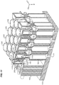
- FIG. 2 is a perspective view of upper tool 110 of molding system 100 in an illustrative embodiment.
- FIG. 2 corresponds with view arrows 2 of FIG. 1 , and upper tool 110 has been rotated with respect to the view shown in FIG. 1 so that upper tool 110 is upside-down.
- FIG. 2 illustrates susceptor 210, which abuts mold 118.
- susceptor 210 engages in conductive heat transfer with mold 118.
- FIG. 3 is a cut-through view of upper tool 110, and corresponds with view arrows 3 of FIG. 2 .
- FIG. 3 illustrates that mold 118 comprises multiple tooling plugs 310 (e.g., individual pieces). Each tooling plug 310, in addition to contacting a susceptor 210, is physically coupled with a support 350.
- Each support 350 includes walls 330. Walls 330 define a chamber 332 which is coupled with hole 111 in base 112.
- Tubes 340 penetrate through holes 111 and chambers 332 into tooling plugs 310.
- Tubes 340 may apply a pressurized cooling fluid (e.g., a cold gas that is below the processing temperature, air, liquid nitrogen, etc.) to reduce the temperature of tooling plugs 310 after molding has completed.
- a pressurized cooling fluid e.g., a cold gas that is below the processing temperature, air, liquid nitrogen, etc.
- FIG. 3 further illustrates slots 320 through which induction coils 116 traverse frame
- FIG. 4 is a perspective view of lower tool 130 of molding system 100 in an illustrative embodiment
- FIG. 5 is a cut-through view of lower tool 130 indicated by view arrows 5 of FIG. 4.
- FIG. 4 illustrates a closer view of susceptor 138, including receptacle 139.
- FIG. 5 illustrates that a size of each slot 135 may vary within frame 134.
- FIG. 6 is a perspective view of molding system 100 in an illustrative embodiment.
- composite part 120 has been inserted into a receptacle 139 defined by susceptor 138.
- FIGS. 7-9 are cut-through views of molding system 100 engaging in molding of composite part 120 in an illustrative embodiment.
- FIG. 7 corresponds with view arrows 7 of FIG. 6 .
- mold 118 is disposed just above composite part 120. Mold 118 is heated by conductive heat transfer with susceptor 138, which is itself heated by induction coils 116. Meanwhile, susceptor 210 may be heated by induction coils 136. After mold 118 is heated to a specific temperature, such as the processing temperature for thermoplastic portion 122, mold 118 shapes thermoplastic portion 122 by moving downward and penetrating into thermoplastic portion 122.
- FIG. 7 also illustrates that frame 114 is composed of a first set 712 of plates 700 of magnetically permeable material (e.g., non-magnetic steel), and that frame 114 is composed of a second set 714 of plates 700 of magnetically permeable material.
- Each plate 700 is separated from another plate 700 by a material 710, disposed between the plates 700, that structurally unites the plates 700 while preventing electrical conduction between the plates 700.
- Material 710 may be implemented for example in ceramic plates that are disposed between plates 700.
- a "magnetically permeable" material is capable of enabling a magnetic field to penetrate through it, without attenuating the magnetic field substantially (e.g., by more than ten percent).
- Plates 700 are also each thinner than a skin depth (e.g., one quarter of an inch) at which their material (e.g., non-magnetic steel) would generate electrical induction current in response to magnetic fields from the induction coils. This is true for plates 700 in frame 114 and frame 134.
- the skin depth is based on a frequency of electrical power being supplied to induction coils that generate electromagnetic fields. Selecting plate thickness in this manner helps to reduce the overall thermal mass of both upper tool 110 and lower tool 130.
- Frame 134 may also be constructed from nonmagnetic, but magnetically permeable components, which ensures that induction coils 116 and 136 do not generate inductive currents within frame 134 or frame 114 that would cause these frames to rapidly heat. At the same time, this ensures that electromagnetic fields generated by induction coils 116 and induction coils 136 are not unduly attenuated.
- FIG. 8 corresponds with the same view shown in FIG. 7 , but illustrates alterations to composite part 120 while it is being molded by mold 118 traveling in direction D.
- FIG. 9 also illustrates composite part 120 during the molding process, and corresponds with view arrows 9 of FIG. 6 .
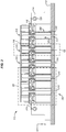
- FIG. 9 illustrates tubes 340, which may disperse a cooling fluid into tooling plugs 310 after a desired shape has been formed via induction molding.
- the cooling fluid reduces the temperature of tooling plugs 310.
- tooling plugs 310 When tooling plugs 310 are cooled, they experience thermal contraction. This in turn enhances the ease with which tooling plugs 310 are removed from thermoplastic portion 122. Additionally, speeding up the cooling process via the use of tubes 140 reduces cycle time when fabricating a large number of parts.
- molding system 100 With a description of the physical components of molding system 100 provided above, an explanation of the molding process follows to illustrate a method by which molding system 100 may be used. Assume, for this embodiment, that composite part 120 includes thermoplastic portion 122, and that upper tool 110 and lower tool 130 are presently separated and not being heated. Molding of thermoplastic portion 122 is desired.
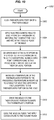
- FIG. 10 is a flowchart illustrating a method for operating a molding system in an illustrative embodiment.
- the steps of method 1000 are described with reference to molding system 100 of FIG. 1 , but those skilled in the art will appreciate that method 1000 may be performed in other systems.
- the steps of the flowcharts described herein are not all inclusive and may include other steps not shown.
- the steps described herein may also be performed in an alternative order.
- Thermoplastic portion 122 of composite part 120 is aligned with mold 118 (step 1002). This may comprise placing composite part 120 into receptacle 139 of susceptor 138. At this point in time, molding system 100 is in position to initiate molding. An electromagnetic field is applied to susceptor 210 of ferromagnetic material that contacts mold 118, as well as additional susceptors 1118 which are inserted into tooling plugs 310 (as illustrated in FIG. 11 ) (step 1004). This operation may be performed by activating induction coils 116 and/or induction coils 136. This generates heat at susceptors 210, 138, and additional susceptors 1118 in response to the electromagnetic field (step 1006).
- Susceptors 138, 210, and additional susceptors 1118 have a Curie point corresponding with (e.g., within ten degrees Celsius of) the processing temperature for thermoplastic portion 122. This means that when susceptors 138, 210, and additional susceptors 1118 are heated substantially towards the processing temperature for thermoplastic portion 122, those susceptors become nonmagnetic and stop heating inductively. This effectively causes the susceptors to achieve a steady-state temperature while being heated by induction coils 116 and 136.
- thermoplastic portion 122 As susceptors 210, 138, and additional susceptors 1118 heat, they increase a temperature of thermoplastic portion 122 to the processing temperature (e.g., two hundred °C) (step 1008). The increase in temperature is at least partly in response to conductive heat transfer from susceptor 210 to thermoplastic portion 122 via mold 118. Upon reaching the processing temperature, thermoplastic portion 122 is capable of being molded. Thus, mold 118 is driven into thermoplastic portion 122 (step 1010). After thermoplastic portion 122 has been shaped, mold 118 may be cooled via tubes 340, which apply a cooling fluid to tooling plugs 310, rapidly cooling tooling plugs 310 and facilitating withdrawal of mold 118 from composite part 120.
- the processing temperature e.g., two hundred °C
- method 1000 may facilitate controlled heated molding of a thermoplastic while limiting waste heat.
- Method 1000 achieves this goal by: inductively heating at least one susceptor that contacts a mold, while preventing inductive heating of structural components that support the mold (owing to structural components of the tools being too thin for inductive heating).
- Method 1000 further engages in molding the thermoplastic by driving the mold into the thermoplastic, and may include cooling the mold by applying a cooling fluid directly to one or more internal chambers (e.g., chamber 332) of the mold.
- Method 1000 provides a substantial advantage over prior systems, because it utilizes enhanced susceptors that are capable of performing "smart” heating instead of runaway thermal heating.
- This smart susceptor technology allows for precise thermal control at the critical processing temperature.
- method 1000 utilizes a molding system which includes parts that are carefully designed and shaped to avoid inductive heating from occurring in other components than the susceptors. By reducing waste heat in this manner, upper tool 110 and lower tool 130 may be rapidly heated and cooled, which increases the fabrication rate of these tools and thereby enhances production efficiency.
- FIGS. 11-12 are zoomed in, cut-through views of regions of the molding system of FIG. 1 in an illustrative embodiment. These views specifically illustrate components of molding system 100. Specifically, FIG. 11 corresponds with region 11 of FIG. 3 , while FIG. 12 corresponds with region 12 of FIG. 3 .
- FIG. 11 illustrates that each tooling plug 310 includes an inner cavity 1114 defined by inner walls 1110. Inner walls 1110 and outer walls 1112 also define outer cavity 1116, into which additional susceptor 1118 is disposed. The use of additional susceptors 1118 within outer cavities 1116 of tooling plugs 310 may enhance the degree of heating provided to tooling plugs 310. While FIG. 11 illustrates additional locations for susceptors which are inserted within mold 118, FIG. 12 illustrates a configuration for a tube 340that cools a tooling plug 310. FIG. 12 illustrates that each tube 340 may include a hollow passage 1210 through which a pressurized cooling fluid travels, exiting through ports 1220 into inner cavities 1114 of each tooling plug 310. Hence, tubes 340, which are inserted into inner cavities 1114, such that tubes 340 are in fluid communication with inner cavities 1114.
- FIG. 13 is a perspective view of a support 350 for tooling plugs within a molding system in an illustrative embodiment.
- support 350 includes a body 1300 which is a hollow cylinder with a slit 1310. Slit 1310 ensures that electrical current pathways do not exist within support 350 which would otherwise result in inductive heating.
- support 350 is attached to mold 118, and is made from a magnetically permeable material (e.g., nonmagnetic stainless steel) that does not increase in temperature by more than a threshold amount (e.g., ten degrees Celsius) in response to the electromagnetic field generated by induction coils within molding system 100.
- Fasteners 1320 attach support 350 to a tooling plug 310, while fasteners 1330 attach support 350 to base 112.
- FIG. 14 is a block diagram illustrating a molding system 1400 in an illustrative embodiment.
- molding system 1400 includes first tool 1410, and second tool 1430.
- Molding system 1400 molds the shape of thermoplastic part 1420.
- First tool 1410 includes base 1412, which includes multiple holes 1411.
- Frame 1413 is also illustrated, which includes multiple plates 1414.
- Slots 1415 within frame 1413 hold induction coils 1416, which are powered by an electrical power supply 1460 and heat susceptors at first tool 1410.
- First tool 1410 further includes supports 1450, which include slits 1452.
- First susceptor 1417 is attached to supports 1450, and tubes 1457 continue through first susceptor 1417 and into tooling plugs 1454. Cooling fluid exits ports 1453 of tubes 1457.
- Tooling plugs 1454 include outer wall 1459, outer (wall) cavity 1455, inner wall 1456, and inner (central) cavity 1458.
- Second tool 1430 includes frame 1433, comprising plates 1434. Slots 1435 continue through plates 1434, and one or more induction coils 1436 are disposed within slots 1435. A second susceptor 1438 is in contact with thermoplastic part 1420 during molding.
- FIG. 15 is a further flowchart illustrating a method 1500 for operating a molding system 100 in an illustrative embodiment.
- method 1500 is utilized for manufacturing a component (e.g., composite part 120) by heating material (e.g., thermoplastic) which forms the component to a predetermined temperature.
- Method 1500 includes placing a material, that will be heated and manufactured into the component, in a receptacle 139 made from a ferromagnetic material that generates inductive current in response to an electromagnetic flux field (in step 1502).
- the receptacle 139 is capable of generating heat to a first predetermined temperature (e.g., one hundred and eighty °C) when subjected to the electromagnetic flux field.
- a first predetermined temperature e.g., one hundred and eighty °C
- Method 1500 further comprises placing a mold 118, made from a ferromagnetic material that generates inductive current in response to the electromagnetic flux field, in the receptacle 139 (step 1504).
- the mold 118 includes a plurality of removable smart susceptor inserts (e.g., additional susceptors 1118), each smart susceptor insert being made from a ferromagnetic material that generates inductive current in response to the electromagnetic flux field to generate heat to a second predetermined temperature (e.g., two hundred and five °C).
- the plurality of smart susceptor inserts and the mold cooperate to achieve a composite predetermined temperature (e.g., two hundred °C) when subjected to the electromagnetic flux field.
- Method 1500 further comprises generating the electromagnetic flux field in proximity to the receptacle and the mold (step 1506).
- method 1500 may comprise preventing electrical conduction between plates that contact the mold 118, generating a first electromagnetic field in a first set of induction coils at a first tool disposed within slots in a first frame, and generating heat in response to the first electromagnetic field to a Curie point within ten degrees Celsius of a processing temperature for a thermoplastic portion of a part.
- illustrative method 1600 may include specification and design 1604 of the aircraft 1602 and material procurement 1606.
- component and subassembly manufacturing 1608 and system integration 1610 of the aircraft 1602 takes place.
- the aircraft 1602 may go through certification and delivery 1612 in order to be placed in service 1614.
- routine maintenance and service 1616 which may also include modification, reconfiguration, refurbishment, and so on).
- Apparatus and methods embodied herein may be employed during any one or more suitable stages of the production and service method 1600 (e.g., specification and design 1604, material procurement 1606, component and subassembly manufacturing 1608, system integration 1610, certification and delivery 1612, service 1614, maintenance and service 1616) and/or any suitable component of aircraft 1602 (e.g., airframe 1618, systems 1620, interior 1622, propulsion 1624, electrical 1626, hydraulic 1628, environmental 1630).
- any suitable component of aircraft 1602 e.g., airframe 1618, systems 1620, interior 1622, propulsion 1624, electrical 1626, hydraulic 1628, environmental 1630.
- a system integrator may include without limitation any number of aircraft manufacturers and major-system subcontractors; a third party may include without limitation any number of vendors, subcontractors, and suppliers; and an operator may be an airline, leasing company, military entity, service organization, and so on.
- the aircraft 1602 produced by illustrative method 1600 may include an airframe 1618 with a plurality of systems 1620 and an interior 1622.
- high-level systems 1620 include one or more of a propulsion system 1624, an electrical system 1626, a hydraulic system 1628, and an environmental system 1630. Any number of other systems may be included.
- an aerospace example is shown, the principles of the invention may be applied to other industries, such as the automotive industry.
- apparatus and methods embodied herein may be employed during any one or more of the stages of the production and service method 1600.
- components or subassemblies corresponding to production stage 1608 may be fabricated or manufactured in a manner similar to components or subassemblies produced while the aircraft 1602 is in service.
- one or more apparatus embodiments, method embodiments, or a combination thereof may be utilized during the production stages 1608 and 1610, for example, by substantially expediting assembly of or reducing the cost of an aircraft 1602.
- apparatus embodiments, method embodiments, or a combination thereof may be utilized while the aircraft 1602 is in service, for example and without limitation, to maintenance and service 1616.
- the techniques and systems described herein may be used for steps 1606, 1608, 1610, 1614, and/or 1616, and/or may be used for airframe 1618 and/or interior 1622. These techniques and systems may even be utilized for systems 1620, including for example propulsion 1624, electrical 1626, hydraulic 1628, and/or environmental 1630.
- a part comprises a portion of airframe 1618, and is manufactured during component and subassembly manufacturing 1608.
- the part may then be assembled into an aircraft in system integration 1610, and then be utilized in service 1614 until wear renders the part unusable.
- the composite part 120 may be discarded and replaced with a newly manufactured part.
- Inventive components and methods described herein may be utilized throughout component and subassembly manufacturing 1608 in order to mold new parts.
- any of the various control elements may be implemented as hardware, a processor implementing software, a processor implementing firmware, or some combination of these.
- an element that controls power to induction coils, or that actuates the tools described above may be implemented as dedicated hardware.
- Dedicated hardware elements may be referred to as "processors", “controllers”, or some similar terminology.
- the functions may be provided by a single dedicated processor, by a single shared processor, or by a plurality of individual processors, some of which may be shared.
- processor or “controller” should not be construed to refer exclusively to hardware capable of executing software, and may implicitly include, without limitation, digital signal processor (DSP) hardware, a network processor, application specific integrated circuit (ASIC) or other circuitry, field programmable gate array (FPGA), read only memory (ROM) for storing software, random access memory (RAM), non-volatile storage, logic, or some other physical hardware component or module.
- DSP digital signal processor
- ASIC application specific integrated circuit
- FPGA field programmable gate array
- ROM read only memory
- RAM random access memory
- non-volatile storage logic, or some other physical hardware component or module.
- a control element may be implemented as instructions executable by a processor or a computer to perform the functions of the element.
- instructions are software, program code, and firmware.
- the instructions are operational when executed by the processor to direct the processor to perform the functions of the element.
- the instructions may be stored on storage devices that are readable by the processor. Some examples of the storage devices are digital or solid-state memories, magnetic storage media such as a magnetic disks and magnetic tapes, hard drives, or optically readable digital data storage media.
Landscapes
- Engineering & Computer Science (AREA)
- Mechanical Engineering (AREA)
- Health & Medical Sciences (AREA)
- Toxicology (AREA)
- Chemical & Material Sciences (AREA)
- Composite Materials (AREA)
- Physics & Mathematics (AREA)
- Electromagnetism (AREA)
- Moulds For Moulding Plastics Or The Like (AREA)
- Heating, Cooling, Or Curing Plastics Or The Like In General (AREA)
- General Induction Heating (AREA)
- Soft Magnetic Materials (AREA)
Abstract
Description
- The disclosure relates to the field of fabrication via molding, and in particular, to molding parts via the use of heated tools.
- Composite parts, such as parts comprising fibres (e.g. carbon fibres) set within a matrix (e.g. a thermoplastic resin), may be fabricated via molding, which involves heating a thermoplastic portion of the part, and pressing the thermoplastic portion of the part into a desired shape. However, it remains a complicated process to ensure that molding is performed consistently at a constant temperature, and without the generation of waste heat. If molding tools have too great of a thermal mass, then the process of molding may consume prohibitive amounts of energy, and the cycle time for fabricating the composite part may be increased, owing to an increased amount of time needed for cooling the mold. Similarly, generation of waste heat in an operating environment is undesirable, as waste heat increases the temperature of the surrounding environment without facilitating molding of parts.
- Therefore, it would be desirable to have a method and apparatus that take into account at least some of the issues discussed above, as well as other possible issues.
- Embodiments described herein provide for induction molding of thermoplastic parts, and utilize "smart" susceptors that transition from magnetic to non-magnetic states when they are close to an induction molding temperature. This ensures that any thermoplastic contacting the smart susceptors will not exceed the induction molding temperature/processing temperature. The apparatus described herein also includes structural components that are thin enough to prevent them from being inductively heated by induction coils within the apparatus. This ensures that inductive heating is applied to the susceptors, and not to the structural components of the apparatus.
- One embodiment is an apparatus that includes a first tool. The first tool includes a first frame. The first frame includes a first set of plates of magnetically permeable material that are parallel with each other and face each other, and a material disposed between plates of the first set that prevents electrical conduction between plates. The first tool also includes a first set of induction coils that are disposed within slots in the first frame and that generate a first electromagnetic field, and a first susceptor that extends from the first set of plates of the first frame. The first susceptor is made of a ferromagnetic material that generates heat in response to the first electromagnetic field, and that has a Curie point within ten degrees Celsius of a processing temperature for a thermoplastic portion of a part. The first tool further includes a mold that extends from the first susceptor and receives heat via conductive heat transfer from the first susceptor. Each plate of the first set is thinner than a skin depth at which the first electromagnetic field would generate an electrical induction current.
- A further embodiment is a method. The method includes applying an electromagnetic field to a susceptor of ferromagnetic material that contacts tooling plugs at_the mold, generating heat at the susceptors in response to the electromagnetic field, the susceptors having a Curie point corresponding with a processing temperature for the thermoplastic portion, and increasing a temperature of the thermoplastic portion to the processing temperature in response to conductive heat transfer from the susceptors to the thermoplastic portion via the mold. The method also includes driving the mold into the thermoplastic portion to shape the thermoplastic portion, and cooling the mold via tubes that apply cooling fluid to the tooling plugs.
- A further embodiment is an apparatus that includes a mold. The mold includes an inner wall made from a magnetically permeable material, an outer wall made from a magnetically permeable material, and a cavity disposed between the inner wall and the outer wall. The apparatus further includes a susceptor, disposed within the cavity, made from a ferromagnetic material that generates heat in response to an electromagnetic field, and a support that is coupled to the mold, and that is made from a magnetically permeable material.
- A further embodiment is a method. The method includes controlling heated molding of a thermoplastic while limiting waste heat. This is performed by inductively heating at least one susceptor that contacts a mold, while preventing inductive heating of structural components that support the mold, molding the thermoplastic by driving the mold into the thermoplastic, and cooling the mold by applying a cooling fluid directly to one or more internal chambers of the mold.
- A further embodiment is a method for manufacturing a component by heating material which forms the component to a predetermined temperature. The method includes placing a material, that will be heated and manufactured into the component, in a receptacle made from a ferromagnetic material that generates inductive current in response to an electromagnetic flux field, the receptacle being capable of generating heat to a first predetermined temperature when subjected to the electromagnetic flux field. The method also includes placing a mold, made from a ferromagnetic material that generates inductive current in response to the electromagnetic flux field, in the receptacle, the mold including a plurality of removable smart susceptor inserts, each smart susceptor insert being made from a ferromagnetic material that generates inductive current in response to the electromagnetic flux field to generate heat to a second predetermined temperature, the plurality of smart susceptor inserts and the mold cooperating to achieve a composite predetermined temperature when subjected to the electromagnetic flux field. The method further includes generating the electromagnetic flux field in proximity to the receptacle and the mold.
- Other illustrative embodiments (e.g., methods and computer-readable media relating to the foregoing embodiments) may be described below. The features, functions, and advantages that have been discussed can be achieved independently in various embodiments or may be combined in yet other embodiments further details of which can be seen with reference to the following description and drawings.
- Some embodiments of the present disclosure are now described, by way of example only, and with reference to the accompanying drawings. The same reference number represents the same element or the same type of element on all drawings.
-
FIG. 1 is an exploded perspective view diagram of a molding system in an illustrative embodiment. -
FIG. 2 is a perspective view of an upper tool of the molding system ofFIG. 1 in an illustrative embodiment. -
FIG. 3 is a cut-through view of an upper tool of the molding system ofFIG. 1 in an illustrative embodiment. -
FIG. 4 is a perspective view of a lower tool of the molding system ofFIG. 1 in an illustrative embodiment. -
FIG. 5 is a cut-through view of a lower tool of the molding system ofFIG. 1 in an illustrative embodiment. -
FIG. 6 is a perspective view of the molding system ofFIG. 1 in an illustrative embodiment. -
FIGS. 7-9 are cut-through views of the molding system ofFIG. 1 in an illustrative embodiment. -
FIG. 10 is a flowchart illustrating a method for operating a molding system in an illustrative embodiment. -
FIGS. 11-12 are zoomed in, cut-through views of regions of the molding system ofFIG. 1 in an illustrative embodiment. -
FIG. 13 is a perspective view of a support for tooling plugs within a molding system in an illustrative embodiment. -
FIG. 14 is a block diagram illustrating a molding system in an illustrative embodiment. -
FIG. 15 is a further flowchart illustrating a method for operating a molding system in an illustrative embodiment. -
FIG. 16 is a flow diagram of aircraft production and service methodology in an illustrative embodiment. -
FIG. 17 is a block diagram of an aircraft in an illustrative embodiment. - The figures and the following description illustrate specific illustrative embodiments of the disclosure. It will thus be appreciated that those skilled in the art will be able to devise various arrangements that, although not explicitly described or shown herein, embody the principles of the disclosure and are included within the scope of the disclosure. Furthermore, any examples described herein are intended to aid in understanding the principles of the disclosure, and are to be construed as being without limitation to such specifically recited examples and conditions. As a result, the disclosure is not limited to the specific embodiments or examples described below, but by the claims and their equivalents.
-
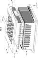
FIGS. 1-9 illustrate views ofmolding system 100 and various components thereof in an illustrative embodiment. For example,FIG. 1 is an exploded perspective view diagram ofmolding system 100 in an illustrative embodiment. In this embodiment,molding system 100 comprisesupper tool 110 andlower tool 130.Upper tool 110 andlower tool 130 unite to shape athermoplastic portion 122 ofcomposite part 120. -
Composite part 120 may comprise a Carbon Fiber Reinforced Polymer (CFRP) part that is initially laid-up in multiple layers that together form a laminate. Individual fibers within each layer of the laminate may be aligned parallel with each other, but different layers may exhibit different fiber orientations in order to increase the strength of the resulting composite part along different dimensions. The laminate may include a liquid resin. The resin solidifies at increased temperature, which hardens the laminate into a composite part (e.g., for use in an aircraft). For thermoset resins, the hardening is a one-way process referred to as curing, while for thermoplastic resins, the resin may return to liquid form if it is re-heated. In some embodiments,composite part 120 may include short chopped fibers (e.g., fibers of a few centimeters in length or less) that are randomly oriented within the part. -
Upper tool 110 includesbase 112, which definesmultiple holes 111.Upper tool 110 also includesframe 114, which is attached tobase 112, as well asfirst set 115 ofinduction coils 116 which penetrate throughframe 114. Induction coils 116 heat one or more susceptors internal toupper tool 110, such assusceptor 210 ofFIG. 2 . The frequency ofinduction coils 116 may be selected to ensure efficient heating of corresponding susceptors. Induction coils 116 may be powered by a power supply (e.g., anelectrical power supply 1460 ofFIG. 14 ). - The susceptors described herein may comprise "smart" susceptors that have a Curie point corresponding with (e.g., within ten degrees Celsius (°C) of) a desired molding temperature/processing temperature (e.g., two hundred °C). Smart susceptors are made from materials that heat asymptotically towards their Curie point, without exceeding their Curie point in the presence of fields generated by surrounding induction coils. This effect is caused by electrical conduction within the susceptors dropping off as the susceptor material demagnetizes. Examples of smart susceptor materials include ferromagnetic materials such as Kovar, and other alloys of iron, nickel, and cobalt. Susceptors described herein may also be made of the same ferromagnetic material if desired.
- Mold 118 forms a lower surface of
upper tool 110, and will touchthermoplastic portion 122 during the molding process.Mold 118 maybe formed from a magnetically permeable material such as non-magnetic stainless steel. In such a case, a thickness of components ofmold 118 may be less than a skin depth at which induction coils 116 would cause induction withinmold 118. Thus, the material does not generate heat in response to the electric field generated byinduction coils 116.Mold 118 may be made from a material distinct from the susceptors described above, for example to reduce cost, ensure a longer tool life, etc.Mold 118 may be shaped into a contour as desired. -
Lower tool 130 comprisesbase 132 andframe 134.Frame 134 definesmultiple slots 135. Inserted intoslots 135 aresecond set 137 of induction coils 136.Induction coils 136 facilitate the generation of heat atsusceptor 138 to increase a temperature ofthermoplastic portion 122 to a processing temperature (e.g., melting point, sticking point, tacking temperature, etc.).Susceptor 138 forms areceptacle 139. In embodiments whereinreceptacle 139 holds loose chopped Poly Ether Ketone Ketone (PEKK) or other thermoplastic,receptacle 139 may be deep enough to hold a desired volume of thermoplastic for molding. -
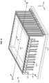
FIG. 2 is a perspective view ofupper tool 110 ofmolding system 100 in an illustrative embodiment.FIG. 2 corresponds with view arrows 2 ofFIG. 1 , andupper tool 110 has been rotated with respect to the view shown inFIG. 1 so thatupper tool 110 is upside-down.FIG. 2 illustratessusceptor 210, which abutsmold 118. Thus, assusceptor 210 is heated byinduction coils 116,susceptor 210 engages in conductive heat transfer withmold 118. -
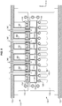
FIG. 3 is a cut-through view ofupper tool 110, and corresponds withview arrows 3 ofFIG. 2 .FIG. 3 illustrates thatmold 118 comprises multiple tooling plugs 310 (e.g., individual pieces). Eachtooling plug 310, in addition to contacting asusceptor 210, is physically coupled with asupport 350. Eachsupport 350 includeswalls 330.Walls 330 define achamber 332 which is coupled withhole 111 inbase 112.Tubes 340 penetrate throughholes 111 andchambers 332 into tooling plugs 310.Tubes 340 may apply a pressurized cooling fluid (e.g., a cold gas that is below the processing temperature, air, liquid nitrogen, etc.) to reduce the temperature of tooling plugs 310 after molding has completed. Thus, the set oftubes 340 is referred to herein as coolingsystem 342.FIG. 3 further illustratesslots 320 through which induction coils 116traverse frame 114. -
FIG. 4 is a perspective view oflower tool 130 ofmolding system 100 in an illustrative embodiment, whileFIG. 5 is a cut-through view oflower tool 130 indicated byview arrows 5 ofFIG. 4. FIG. 4 illustrates a closer view ofsusceptor 138, includingreceptacle 139.FIG. 5 illustrates that a size of eachslot 135 may vary withinframe 134. - With a description provided for both
upper tool 110 andlower tool 130, the molding process is illustrated inFIGS. 6-9 .FIG. 6 is a perspective view ofmolding system 100 in an illustrative embodiment. In this view,composite part 120 has been inserted into areceptacle 139 defined bysusceptor 138. -
FIGS. 7-9 are cut-through views ofmolding system 100 engaging in molding ofcomposite part 120 in an illustrative embodiment.FIG. 7 corresponds withview arrows 7 ofFIG. 6 . As shown inFIG. 7 ,mold 118 is disposed just abovecomposite part 120.Mold 118 is heated by conductive heat transfer withsusceptor 138, which is itself heated byinduction coils 116. Meanwhile,susceptor 210 may be heated byinduction coils 136. Aftermold 118 is heated to a specific temperature, such as the processing temperature forthermoplastic portion 122,mold 118 shapesthermoplastic portion 122 by moving downward and penetrating intothermoplastic portion 122. -
FIG. 7 also illustrates thatframe 114 is composed of afirst set 712 ofplates 700 of magnetically permeable material (e.g., non-magnetic steel), and thatframe 114 is composed of asecond set 714 ofplates 700 of magnetically permeable material. Eachplate 700 is separated from anotherplate 700 by amaterial 710, disposed between theplates 700, that structurally unites theplates 700 while preventing electrical conduction between theplates 700.Material 710 may be implemented for example in ceramic plates that are disposed betweenplates 700. As used herein, a "magnetically permeable" material is capable of enabling a magnetic field to penetrate through it, without attenuating the magnetic field substantially (e.g., by more than ten percent).Plates 700 are also each thinner than a skin depth (e.g., one quarter of an inch) at which their material (e.g., non-magnetic steel) would generate electrical induction current in response to magnetic fields from the induction coils. This is true forplates 700 inframe 114 andframe 134. The skin depth is based on a frequency of electrical power being supplied to induction coils that generate electromagnetic fields. Selecting plate thickness in this manner helps to reduce the overall thermal mass of bothupper tool 110 andlower tool 130. -
Frame 134 may also be constructed from nonmagnetic, but magnetically permeable components, which ensures that induction coils 116 and 136 do not generate inductive currents withinframe 134 orframe 114 that would cause these frames to rapidly heat. At the same time, this ensures that electromagnetic fields generated byinduction coils 116 andinduction coils 136 are not unduly attenuated.FIG. 8 corresponds with the same view shown inFIG. 7 , but illustrates alterations tocomposite part 120 while it is being molded bymold 118 traveling in direction D. -
FIG. 9 also illustratescomposite part 120 during the molding process, and corresponds with view arrows 9 ofFIG. 6 .FIG. 9 illustratestubes 340, which may disperse a cooling fluid into tooling plugs 310 after a desired shape has been formed via induction molding. The cooling fluid reduces the temperature of tooling plugs 310. When tooling plugs 310 are cooled, they experience thermal contraction. This in turn enhances the ease with which tooling plugs 310 are removed fromthermoplastic portion 122. Additionally, speeding up the cooling process via the use oftubes 140 reduces cycle time when fabricating a large number of parts. - With a description of the physical components of
molding system 100 provided above, an explanation of the molding process follows to illustrate a method by whichmolding system 100 may be used. Assume, for this embodiment, thatcomposite part 120 includesthermoplastic portion 122, and thatupper tool 110 andlower tool 130 are presently separated and not being heated. Molding ofthermoplastic portion 122 is desired. -
FIG. 10 is a flowchart illustrating a method for operating a molding system in an illustrative embodiment. The steps ofmethod 1000 are described with reference tomolding system 100 ofFIG. 1 , but those skilled in the art will appreciate thatmethod 1000 may be performed in other systems. The steps of the flowcharts described herein are not all inclusive and may include other steps not shown. The steps described herein may also be performed in an alternative order. -
Thermoplastic portion 122 ofcomposite part 120 is aligned with mold 118 (step 1002). This may comprise placingcomposite part 120 intoreceptacle 139 ofsusceptor 138. At this point in time,molding system 100 is in position to initiate molding. An electromagnetic field is applied tosusceptor 210 of ferromagnetic material thatcontacts mold 118, as well asadditional susceptors 1118 which are inserted into tooling plugs 310 (as illustrated inFIG. 11 ) (step 1004). This operation may be performed by activatinginduction coils 116 and/or induction coils 136. This generates heat atsusceptors additional susceptors 1118 in response to the electromagnetic field (step 1006).Susceptors additional susceptors 1118 have a Curie point corresponding with (e.g., within ten degrees Celsius of) the processing temperature forthermoplastic portion 122. This means that whensusceptors additional susceptors 1118 are heated substantially towards the processing temperature forthermoplastic portion 122, those susceptors become nonmagnetic and stop heating inductively. This effectively causes the susceptors to achieve a steady-state temperature while being heated byinduction coils - As
susceptors additional susceptors 1118 heat, they increase a temperature ofthermoplastic portion 122 to the processing temperature (e.g., two hundred °C) (step 1008). The increase in temperature is at least partly in response to conductive heat transfer fromsusceptor 210 tothermoplastic portion 122 viamold 118. Upon reaching the processing temperature,thermoplastic portion 122 is capable of being molded. Thus,mold 118 is driven into thermoplastic portion 122 (step 1010). Afterthermoplastic portion 122 has been shaped,mold 118 may be cooled viatubes 340, which apply a cooling fluid to tooling plugs 310, rapidly cooling tooling plugs 310 and facilitating withdrawal ofmold 118 fromcomposite part 120. - In summation,
method 1000 may facilitate controlled heated molding of a thermoplastic while limiting waste heat.Method 1000 achieves this goal by: inductively heating at least one susceptor that contacts a mold, while preventing inductive heating of structural components that support the mold (owing to structural components of the tools being too thin for inductive heating).Method 1000 further engages in molding the thermoplastic by driving the mold into the thermoplastic, and may include cooling the mold by applying a cooling fluid directly to one or more internal chambers (e.g., chamber 332) of the mold. -
Method 1000 provides a substantial advantage over prior systems, because it utilizes enhanced susceptors that are capable of performing "smart" heating instead of runaway thermal heating. This smart susceptor technology allows for precise thermal control at the critical processing temperature. Furthermore,method 1000 utilizes a molding system which includes parts that are carefully designed and shaped to avoid inductive heating from occurring in other components than the susceptors. By reducing waste heat in this manner,upper tool 110 andlower tool 130 may be rapidly heated and cooled, which increases the fabrication rate of these tools and thereby enhances production efficiency. - With a discussion of the components and operations of
molding system 100 provided above,FIGS. 11-12 are zoomed in, cut-through views of regions of the molding system ofFIG. 1 in an illustrative embodiment. These views specifically illustrate components ofmolding system 100. Specifically,FIG. 11 corresponds withregion 11 ofFIG. 3 , whileFIG. 12 corresponds withregion 12 ofFIG. 3 . -
FIG. 11 illustrates that eachtooling plug 310 includes aninner cavity 1114 defined byinner walls 1110.Inner walls 1110 andouter walls 1112 also define outer cavity 1116, into whichadditional susceptor 1118 is disposed. The use ofadditional susceptors 1118 within outer cavities 1116 of tooling plugs 310 may enhance the degree of heating provided to tooling plugs 310. WhileFIG. 11 illustrates additional locations for susceptors which are inserted withinmold 118,FIG. 12 illustrates a configuration for a tube 340that cools atooling plug 310.FIG. 12 illustrates that eachtube 340 may include ahollow passage 1210 through which a pressurized cooling fluid travels, exiting throughports 1220 intoinner cavities 1114 of eachtooling plug 310. Hence,tubes 340, which are inserted intoinner cavities 1114, such thattubes 340 are in fluid communication withinner cavities 1114. -
FIG. 13 is a perspective view of asupport 350 for tooling plugs within a molding system in an illustrative embodiment. In this embodiment,support 350 includes abody 1300 which is a hollow cylinder with aslit 1310.Slit 1310 ensures that electrical current pathways do not exist withinsupport 350 which would otherwise result in inductive heating. Furthermore,support 350 is attached to mold 118, and is made from a magnetically permeable material (e.g., nonmagnetic stainless steel) that does not increase in temperature by more than a threshold amount (e.g., ten degrees Celsius) in response to the electromagnetic field generated by induction coils withinmolding system 100.Fasteners 1320 attachsupport 350 to atooling plug 310, whilefasteners 1330 attachsupport 350 tobase 112. - In the following examples, additional processes, systems, and methods are described in the context of an inductive molding system.
-
FIG. 14 is a block diagram illustrating amolding system 1400 in an illustrative embodiment. According toFIG. 14 ,molding system 1400 includesfirst tool 1410, and second tool 1430.Molding system 1400 molds the shape ofthermoplastic part 1420.First tool 1410 includesbase 1412, which includesmultiple holes 1411.Frame 1413 is also illustrated, which includesmultiple plates 1414.Slots 1415 withinframe 1413hold induction coils 1416, which are powered by anelectrical power supply 1460 and heat susceptors atfirst tool 1410. -
First tool 1410 further includessupports 1450, which include slits 1452. First susceptor 1417 is attached tosupports 1450, andtubes 1457 continue through first susceptor 1417 and into tooling plugs 1454. Cooling fluid exitsports 1453 oftubes 1457. Tooling plugs 1454 includeouter wall 1459, outer (wall)cavity 1455,inner wall 1456, and inner (central)cavity 1458. - Second tool 1430 includes
frame 1433, comprisingplates 1434.Slots 1435 continue throughplates 1434, and one ormore induction coils 1436 are disposed withinslots 1435. A second susceptor 1438 is in contact withthermoplastic part 1420 during molding. -
FIG. 15 is a further flowchart illustrating amethod 1500 for operating amolding system 100 in an illustrative embodiment. According toFIG. 15 ,method 1500 is utilized for manufacturing a component (e.g., composite part 120) by heating material (e.g., thermoplastic) which forms the component to a predetermined temperature.Method 1500 includes placing a material, that will be heated and manufactured into the component, in areceptacle 139 made from a ferromagnetic material that generates inductive current in response to an electromagnetic flux field (in step 1502). Thereceptacle 139 is capable of generating heat to a first predetermined temperature (e.g., one hundred and eighty °C) when subjected to the electromagnetic flux field.Method 1500 further comprises placing amold 118, made from a ferromagnetic material that generates inductive current in response to the electromagnetic flux field, in the receptacle 139 (step 1504). Themold 118 includes a plurality of removable smart susceptor inserts (e.g., additional susceptors 1118), each smart susceptor insert being made from a ferromagnetic material that generates inductive current in response to the electromagnetic flux field to generate heat to a second predetermined temperature (e.g., two hundred and five °C). The plurality of smart susceptor inserts and the mold cooperate to achieve a composite predetermined temperature (e.g., two hundred °C) when subjected to the electromagnetic flux field.Method 1500 further comprises generating the electromagnetic flux field in proximity to the receptacle and the mold (step 1506). - In further embodiments,
method 1500 may comprise preventing electrical conduction between plates that contact themold 118, generating a first electromagnetic field in a first set of induction coils at a first tool disposed within slots in a first frame, and generating heat in response to the first electromagnetic field to a Curie point within ten degrees Celsius of a processing temperature for a thermoplastic portion of a part. - Referring more particularly to the drawings, embodiments of the disclosure may be described in the context of an aircraft manufacturing and
service method 1600 as shown inFIG. 16 and an aircraft 1602 as shown inFIG. 17 . During pre-production,illustrative method 1600 may include specification anddesign 1604 of the aircraft 1602 andmaterial procurement 1606. During production, component andsubassembly manufacturing 1608 andsystem integration 1610 of the aircraft 1602 takes place. Thereafter, the aircraft 1602 may go through certification anddelivery 1612 in order to be placed inservice 1614. While in service by a customer, the aircraft 1602 is scheduled for routine maintenance and service 1616 (which may also include modification, reconfiguration, refurbishment, and so on). Apparatus and methods embodied herein may be employed during any one or more suitable stages of the production and service method 1600 (e.g., specification anddesign 1604,material procurement 1606, component andsubassembly manufacturing 1608,system integration 1610, certification anddelivery 1612,service 1614, maintenance and service 1616) and/or any suitable component of aircraft 1602 (e.g., airframe 1618, systems 1620, interior 1622, propulsion 1624, electrical 1626, hydraulic 1628, environmental 1630). - Each of the processes of
method 1600 may be performed or carried out by a system integrator, a third party, and/or an operator (e.g., a customer). For the purposes of this description, a system integrator may include without limitation any number of aircraft manufacturers and major-system subcontractors; a third party may include without limitation any number of vendors, subcontractors, and suppliers; and an operator may be an airline, leasing company, military entity, service organization, and so on. - As shown in
FIG. 17 , the aircraft 1602 produced byillustrative method 1600 may include an airframe 1618 with a plurality of systems 1620 and an interior 1622. Examples of high-level systems 1620 include one or more of a propulsion system 1624, an electrical system 1626, a hydraulic system 1628, and an environmental system 1630. Any number of other systems may be included. Although an aerospace example is shown, the principles of the invention may be applied to other industries, such as the automotive industry. - As already mentioned above, apparatus and methods embodied herein may be employed during any one or more of the stages of the production and
service method 1600. For example, components or subassemblies corresponding toproduction stage 1608 may be fabricated or manufactured in a manner similar to components or subassemblies produced while the aircraft 1602 is in service. Also, one or more apparatus embodiments, method embodiments, or a combination thereof may be utilized during theproduction stages service 1616. For example, the techniques and systems described herein may be used forsteps - In one embodiment, a part comprises a portion of airframe 1618, and is manufactured during component and
subassembly manufacturing 1608. The part may then be assembled into an aircraft insystem integration 1610, and then be utilized inservice 1614 until wear renders the part unusable. Then, in maintenance andservice 1616, thecomposite part 120 may be discarded and replaced with a newly manufactured part. Inventive components and methods described herein may be utilized throughout component andsubassembly manufacturing 1608 in order to mold new parts. - Any of the various control elements (e.g., electrical or electronic components) shown in the figures or described herein may be implemented as hardware, a processor implementing software, a processor implementing firmware, or some combination of these. For example, an element that controls power to induction coils, or that actuates the tools described above, may be implemented as dedicated hardware. Dedicated hardware elements may be referred to as "processors", "controllers", or some similar terminology. When provided by a processor, the functions may be provided by a single dedicated processor, by a single shared processor, or by a plurality of individual processors, some of which may be shared. Moreover, explicit use of the term "processor" or "controller" should not be construed to refer exclusively to hardware capable of executing software, and may implicitly include, without limitation, digital signal processor (DSP) hardware, a network processor, application specific integrated circuit (ASIC) or other circuitry, field programmable gate array (FPGA), read only memory (ROM) for storing software, random access memory (RAM), non-volatile storage, logic, or some other physical hardware component or module.
- Also, a control element may be implemented as instructions executable by a processor or a computer to perform the functions of the element. Some examples of instructions are software, program code, and firmware. The instructions are operational when executed by the processor to direct the processor to perform the functions of the element. The instructions may be stored on storage devices that are readable by the processor. Some examples of the storage devices are digital or solid-state memories, magnetic storage media such as a magnetic disks and magnetic tapes, hard drives, or optically readable digital data storage media.
- The present invention is also referred to in the following clauses which are not to be confused with the claims.
- A1. An apparatus (100) comprising: a first tool (110) comprising: a first frame (114) comprising: a first set (712) of plates (700) of magnetically permeable material that are parallel with each other and face each other; and a material (710), disposed between plates of the first set, that prevents electrical conduction between plates; a first set (115) of induction coils (116) that are disposed within slots (135) in the first frame and that generate a first electromagnetic field; a first susceptor that (210) extends from the first set of plates of the first frame, the first susceptor is made of a ferromagnetic material that generates heat in response to the first electromagnetic field, and that has a Curie point within ten degrees Celsius of a processing temperature for a thermoplastic portion of a part (120); and a mold (118) that extends from the first susceptor and receives heat via conductive heat transfer from the first susceptor, each plate of the first set is thinner than a skin depth at which the first electromagnetic field would generate an electrical induction current.
- A2. The apparatus of clause A1 further comprising a second tool (130) comprising: a second frame (134) comprising: a second set (714) of plates (700) of magnetically permeable material that are parallel with each other and face each other; and a material (710), disposed between plates of the second set, that prevent electrical conduction between plates; a second set (137) of induction coils (136) that are disposed within slots (135) in the second frame and that generate a second electromagnetic field; and a second susceptor (138) of ferromagnetic material that generates heat in response to the second electromagnetic field, the second susceptor is recessed within the second frame and defines a receptacle (139) that is dimensioned to receive the mold, each plate of the second set is thinner than the skin depth.
- A3. The apparatus of clause A2 wherein: the first susceptor and the second susceptor each comprise an alloy of iron, nickel, and cobalt.
- A4. The apparatus of any of clauses A1 to A3 further comprising: additional susceptors (1118) that are inserted into the mold, and that are made from a ferromagnetic material that generates heat in response to the first electromagnetic field.
- A5. The apparatus of clause A4 wherein: the mold comprises an inner wall (1110) that does not contact the part and an outer wall (1112) that contacts the part, and the additional susceptors are inserted between the inner wall and the outer wall.
- A6. The apparatus of clause A5 wherein: the magnetically permeable material forming the first set of plates is non-magnetic stainless steel.
- A7. The apparatus of any of clauses A1 to A6 wherein: the skin depth is based on a frequency of electrical power being supplied to the first set of induction coils to generate the first electromagnetic field.
- A8. The apparatus of any of clauses A1 to A7 wherein: the mold is made from a ferromagnetic material that is chemically distinct from the ferromagnetic material of the first susceptor.
- A9. The apparatus of any of clauses A1 to A8 wherein: the mold is includes walls (1110, 1112) that are thinner than a skin depth at which the first electromagnetic field would generate an electrical induction current within the mold.
- A10. The apparatus of any of clauses A1 to A9 further comprising: a support (350) that is attached to the mold and that is made from a magnetically permeable material.
- A11. The apparatus of clause A10 wherein: the support is made from non-magnetic stainless steel.
- A12. The apparatus of clause A10 or A11 wherein: the support is thinner than a skin depth at which the first electromagnetic field would generate an electrical induction current within the support.
- A13. The apparatus of any of clauses A10 to A12 wherein: the support comprises a hollow cylinder that includes a slit (1310) extending along a length of the hollow cylinder.
- A14. The apparatus of any of clauses A1 to A13 further comprising: a cooling system (342) that applies a fluid to the mold which cools the mold below a processing temperature.
- A15. The apparatus of clause A14 wherein: the mold comprises multiple inner cavities (1114); and the cooling system (342) is in fluid communication with the inner cavities.
- A16. The apparatus of clause A15 wherein: the cooling system comprises tubes (340) inserted into the inner cavities.
- A17. The apparatus of paragraph A16 wherein: each tube comprises a port (1220) that enables fluid to travel from the tube to an inner cavity (1114).
- A18. The apparatus of any of clauses A1 to A17 further comprising: an electrical power supply (1460) that supplies power to the first set of induction coils.
- A19. The apparatus of any of clauses A1 to A18, wherein: the magnetically permeable material forming the mold is non-magnetic stainless steel.
- B1. An apparatus comprising: an induction coil (116) that generates an electromagnetic field; and a tool (100) positioned in the electromagnetic field, the tool comprising: a mold (118) of magnetically permeable material; a first susceptor (138) that is positioned in the electromagnetic field and defines a receptacle (139) that is dimensioned to receive the mold; and a plurality of additional susceptors (1118) that are inserted into cavities (1114) within the mold.
- B2. The apparatus of clause B1 further comprising: a support (350) that is coupled to the mold, the support is made from a magnetically permeable material that does not generate heat in response to the electromagnetic field.
- B3. The apparatus of clause B1 or B2 further comprising: an electrical power supply (1460) that supplies power to the induction coil.
- C1. A method for manufacturing a component by heating material which forms the component to a predetermined temperature, the method comprising: placing a material, that will be heated and manufactured into the component, in a receptacle made from a ferromagnetic material that generates inductive current in response to an electromagnetic flux field, the receptacle being capable of generating heat to a first predetermined temperature when subjected to the electromagnetic flux field (1502); placing a mold, made from a ferromagnetic material that generates inductive current in response to the electromagnetic flux field, in the receptacle, the mold including a plurality of removable smart susceptor inserts, each smart susceptor insert being made from a ferromagnetic material that generates inductive current in response to the electromagnetic flux field to generate heat to a second predetermined temperature, the plurality of smart susceptor inserts and the mold cooperating to achieve a composite predetermined temperature when subjected to the electromagnetic flux field (1504); and generating the electromagnetic flux field in proximity to the receptacle and the mold (1506).
- C2. The method of clause C1, further comprising: preventing electrical conduction between plates that contact the mold; generating a first electromagnetic field in a first set of induction coils at a first tool disposed within slots in a first frame; and generating heat in response to the first electromagnetic field to a Curie point within ten degrees Celsius of a processing temperature for a thermoplastic portion of a part.
- C3. A portion of an aircraft assembled according to the method of clause C1 or C2.
- C4. A portion of an aircraft comprising a component manufactured according to the method of clause C1 or C2.
- C5 An aircraft comprising a component manufactured according to the method of clause C1 or C2.
- D1. A method comprising: applying an electromagnetic field to a susceptor of ferromagnetic material that contacts tooling plugs at a mold (1004); generating heat at the susceptors in response to the electromagnetic field, the susceptors having a Curie point corresponding with a processing temperature for a thermoplastic portion of a part (1006); increasing a temperature of the thermoplastic portion to the processing temperature in response to conductive heat transfer from the susceptors to the thermoplastic portion via the mold (1008); driving the mold into the thermoplastic portion to shape the thermoplastic portion (1010); and cooling the mold via tubes that apply cooling fluid to the tooling plugs (1012).
- D2. The method of clause D1 further comprising: heating the susceptor to the Curie point.
- E1. An apparatus comprising: a mold (118) that comprises an inner wall (1110) made from a magnetically permeable material, an outer wall (1112) made from a magnetically permeable material, and a cavity (1114) disposed between the inner wall and the outer wall; a susceptor (1118), disposed within the cavity, made from a ferromagnetic material that generates heat in response to an electromagnetic field; and a support (350) that is coupled to the mold, and that is made from a magnetically permeable material.
- E2. The apparatus of clause E1 wherein: the support is thinner than a skin depth at which the electromagnetic field would generate an electrical induction current within the support.
- E3. The apparatus of clause E1 or E2 wherein: the cavity corresponds in size with the susceptor.
- E4. The apparatus of any of clauses E1 to E3 further comprising: a cooling system (342) that applies a fluid to the cavity which cools the mold below a processing temperature for a thermoplastic portion of a part (120).
- E5. The apparatus of any of clauses E1 to E4 wherein: the support comprises a hollow cylinder that includes a slit (1310) extending along a length of the hollow cylinder.
- F1. A method comprising: controlling heated molding of a thermoplastic while limiting waste heat by: inductively heating at least one susceptor that contacts a mold, while preventing inductive heating of structural components that support the mold (1006); molding the thermoplastic by driving the mold into the thermoplastic (1010); and cooling the mold by applying a cooling fluid directly to one or more internal chambers of the mold (1012).
- F2. The method of clause F1 further comprising: heating the at least one susceptor to the Curie point.
- Although specific embodiments are described herein, the scope of the disclosure is not limited to those specific embodiments. The scope of the disclosure is defined by the following claims and any equivalents thereof.
Claims (15)
- An apparatus (100) comprising:a first tool (110) comprising:a first frame (114) comprising:a first set (712) of plates (700) of magnetically permeable material that are parallel with each other and face each other; anda material (710), disposed between plates of the first set, that prevents electrical conduction between plates;a first set (115) of induction coils (116) that are disposed within slots (135) in the first frame and that generate a first electromagnetic field;a first susceptor that (210) extends from the first set of plates of the first frame, the first susceptor is made of a ferromagnetic material that generates heat in response to the first electromagnetic field, and that has a Curie point within ten degrees Celsius of a processing temperature for a thermoplastic portion of a part (120); anda mold (118) that extends from the first susceptor and receives heat via conductive heat transfer from the first susceptor,each plate of the first set is thinner than a skin depth at which the first electromagnetic field would generate an electrical induction current.
- The apparatus of claim 1 further comprisinga second tool (130) comprising:a second frame (134) comprising:a second set (714) of plates (700) of magnetically permeable material that are parallel with each other and face each other; anda material (710), disposed between plates of the second set, that prevent electrical conduction between plates;a second set (137) of induction coils (136) that are disposed within slots (135) in the second frame and that generate a second electromagnetic field; anda second susceptor (138) of ferromagnetic material that generates heat in response to the second electromagnetic field, the second susceptor is recessed within the second frame and defines a receptacle (139) that is dimensioned to receive the mold,each plate of the second set is thinner than the skin depth.
- The apparatus of claim 2 wherein:the first susceptor and the second susceptor each comprise an alloy of iron, nickel, and cobalt.
- The apparatus of any preceding claim further comprising:additional susceptors (1118) that are inserted into the mold, and that are made from a ferromagnetic material that generates heat in response to the first electromagnetic field.
- The apparatus of claim 4 wherein:the mold comprises an inner wall (1110) that does not contact the part and an outer wall (1112) that contacts the part, andthe additional susceptors are inserted between the inner wall and the outer wall.
- The apparatus of claim 5 wherein:the magnetically permeable material forming the first set of plates is non-magnetic stainless steel.
- The apparatus of any preceding claim wherein:the skin depth is based on a frequency of electrical power being supplied to the first set of induction coils to generate the first electromagnetic field.
- The apparatus of any preceding claim wherein:the mold is made from a ferromagnetic material that is chemically distinct from the ferromagnetic material of the first susceptor.
- The apparatus of any preceding claim wherein:the mold is includes walls (1110, 1112) that are thinner than a skin depth at which the first electromagnetic field would generate an electrical induction current within the mold.
- The apparatus of any preceding claim further comprising:a support (350) that is attached to the mold and that is made from a magnetically permeable material.
- The apparatus of any preceding claim further comprising:a cooling system (342) that applies a fluid to the mold which cools the mold below a processing temperature.
- The apparatus of any preceding claim further comprising:an electrical power supply (1460) that supplies power to the first set of induction coils.
- The apparatus of any preceding claim, wherein:the magnetically permeable material forming the mold is non-magnetic stainless steel.
- A method for manufacturing a component by heating material which forms the component to a predetermined temperature, the method comprising:placing a material, that will be heated and manufactured into the component, in a receptacle made from a ferromagnetic material that generates inductive current in response to an electromagnetic flux field, the receptacle being capable of generating heat to a first predetermined temperature when subjected to the electromagnetic flux field (1502);placing a mold, made from a ferromagnetic material that generates inductive current in response to the electromagnetic flux field, in the receptacle, the mold including a plurality of removable smart susceptor inserts, each smart susceptor insert being made from a ferromagnetic material that generates inductive current in response to the electromagnetic flux field to generate heat to a second predetermined temperature, the plurality of smart susceptor inserts and the mold cooperating to achieve a composite predetermined temperature when subjected to the electromagnetic flux field (1504); andgenerating the electromagnetic flux field in proximity to the receptacle and the mold (1506).
- The method of claim 14, further comprising:preventing electrical conduction between plates that contact the mold;generating a first electromagnetic field in a first set of induction coils at a first tool disposed within slots in a first frame; andgenerating heat in response to the first electromagnetic field to a Curie point within ten degrees Celsius of a processing temperature for a thermoplastic portion of a part.
Applications Claiming Priority (1)
| Application Number | Priority Date | Filing Date | Title |
|---|---|---|---|
| US15/791,683 US10792842B2 (en) | 2017-10-24 | 2017-10-24 | Induction molding for parts having thermoplastic portions |
Publications (3)
| Publication Number | Publication Date |
|---|---|
| EP3487262A2 true EP3487262A2 (en) | 2019-05-22 |
| EP3487262A3 EP3487262A3 (en) | 2019-08-21 |
| EP3487262B1 EP3487262B1 (en) | 2023-05-24 |
Family
ID=63787789
Family Applications (1)
| Application Number | Title | Priority Date | Filing Date |
|---|---|---|---|
| EP18198804.9A Active EP3487262B1 (en) | 2017-10-24 | 2018-10-05 | Induction molding for parts having thermoplastic portions |
Country Status (6)
| Country | Link |
|---|---|
| US (1) | US10792842B2 (en) |
| EP (1) | EP3487262B1 (en) |
| JP (2) | JP7210215B2 (en) |
| CN (1) | CN109693363B (en) |
| CA (1) | CA3013612C (en) |
| ES (1) | ES2945909T3 (en) |
Cited By (1)
| Publication number | Priority date | Publication date | Assignee | Title |
|---|---|---|---|---|
| EP3761758A1 (en) * | 2019-07-01 | 2021-01-06 | The Boeing Company | Charge heating method and systems for induction molding |
Families Citing this family (7)
| Publication number | Priority date | Publication date | Assignee | Title |
|---|---|---|---|---|
| US10792842B2 (en) * | 2017-10-24 | 2020-10-06 | The Boeing Company | Induction molding for parts having thermoplastic portions |
| US10981296B2 (en) | 2019-05-22 | 2021-04-20 | The Boeing Company | System and method for preheating a thermoplastic charge |
| US12103249B2 (en) | 2021-08-30 | 2024-10-01 | The Boeing Company | Composite forming apparatus, methods, and systems |
| US11999116B2 (en) | 2021-08-30 | 2024-06-04 | The Boeing Company | Composite forming apparatus, system and method |
| US11897209B2 (en) | 2021-08-30 | 2024-02-13 | The Boeing Company | Composite forming apparatus, system and method |
| US12138864B2 (en) | 2021-08-30 | 2024-11-12 | The Boeing Company | Forming apparatus, methods, and systems |
| CN115682433B (en) * | 2022-10-26 | 2025-11-18 | 东莞市双平电源技术有限公司 | A fluid heating device combining high-frequency resistance heating and induction heating |
Family Cites Families (18)
| Publication number | Priority date | Publication date | Assignee | Title |
|---|---|---|---|---|
| AU7928394A (en) * | 1993-10-07 | 1995-05-01 | Hayes Wheels International, Inc. | Method and apparatus for controlled directional solidification of a wheel casting |
| US6566635B1 (en) | 2002-03-08 | 2003-05-20 | The Boeing Company | Smart susceptor having a geometrically complex molding surface |
| CN100438709C (en) * | 2003-07-15 | 2008-11-26 | 松下电器产业株式会社 | induction heating device |
| US6979807B2 (en) | 2003-08-13 | 2005-12-27 | The Boeing Company | Forming apparatus and method |
| US8017059B2 (en) | 2007-09-13 | 2011-09-13 | The Boeing Company | Composite fabrication apparatus and method |
| US8383998B1 (en) * | 2009-11-02 | 2013-02-26 | The Boeing Company | Tooling inserts for laminated tooling |
| JP5443138B2 (en) * | 2009-11-24 | 2014-03-19 | 株式会社 サン・テクトロ | Apparatus and method for molding composite laminate material body |
| JP5967834B2 (en) * | 2011-03-31 | 2016-08-10 | 広島県 | Resin molding die, method for manufacturing the resin molding die, and method for manufacturing a resin molded product |
| JP2013000947A (en) * | 2011-06-15 | 2013-01-07 | Honda Motor Co Ltd | Workpiece forming mold |
| US8963058B2 (en) | 2011-11-28 | 2015-02-24 | The Boeing Company | System and method of adjusting the equilibrium temperature of an inductively-heated susceptor |
| US8770968B2 (en) * | 2012-04-13 | 2014-07-08 | GM Global Technology Operations LLC | Injection molding tool with embedded induction heater |
| FR2991902A1 (en) | 2012-06-18 | 2013-12-20 | Roctool | METHOD AND DEVICE FOR PREHEATING A MOLD IN PARTICULAR INJECTION MOLDING |
| US9635714B2 (en) * | 2013-05-06 | 2017-04-25 | The Boeing Company | Incremental sheet forming for fabrication of cold sprayed smart susceptor |
| JP5793167B2 (en) * | 2013-07-25 | 2015-10-14 | 株式会社山田工作所 | Sheet forming mold for pressure forming and pressure forming machine |
| US10059054B2 (en) * | 2015-06-29 | 2018-08-28 | The Boeing Company | Welding thermoplastic structures |
| US11224992B2 (en) | 2015-10-26 | 2022-01-18 | The Boeing Company | Heating of thermoplastic interlayers in a preform tool for producing a preform of a composite member |
| US11186046B2 (en) * | 2017-06-29 | 2021-11-30 | The Boeing Company | Induction curing of cell-based structural arrays |
| US10792842B2 (en) * | 2017-10-24 | 2020-10-06 | The Boeing Company | Induction molding for parts having thermoplastic portions |
-
2017
- 2017-10-24 US US15/791,683 patent/US10792842B2/en active Active
-
2018
- 2018-08-08 CA CA3013612A patent/CA3013612C/en active Active
- 2018-09-05 CN CN201811030653.9A patent/CN109693363B/en active Active
- 2018-10-05 EP EP18198804.9A patent/EP3487262B1/en active Active
- 2018-10-05 ES ES18198804T patent/ES2945909T3/en active Active
- 2018-10-10 JP JP2018191743A patent/JP7210215B2/en active Active
-
2023
- 2023-01-11 JP JP2023002304A patent/JP7403011B2/en active Active
Non-Patent Citations (1)
| Title |
|---|
| None |
Cited By (2)
| Publication number | Priority date | Publication date | Assignee | Title |
|---|---|---|---|---|
| EP3761758A1 (en) * | 2019-07-01 | 2021-01-06 | The Boeing Company | Charge heating method and systems for induction molding |
| US11758622B2 (en) | 2019-07-01 | 2023-09-12 | The Boeing Company | Charge heating method and systems for induction molding |
Also Published As
| Publication number | Publication date |
|---|---|
| US10792842B2 (en) | 2020-10-06 |
| EP3487262B1 (en) | 2023-05-24 |
| CA3013612A1 (en) | 2019-04-24 |
| EP3487262A3 (en) | 2019-08-21 |
| JP7403011B2 (en) | 2023-12-21 |
| CN109693363A (en) | 2019-04-30 |
| CN109693363B (en) | 2022-06-10 |
| US20190118415A1 (en) | 2019-04-25 |
| CA3013612C (en) | 2025-09-02 |
| ES2945909T3 (en) | 2023-07-10 |
| JP2019077179A (en) | 2019-05-23 |
| JP7210215B2 (en) | 2023-01-23 |
| JP2023052317A (en) | 2023-04-11 |
Similar Documents
| Publication | Publication Date | Title |
|---|---|---|
| CA3013612C (en) | Induction molding for parts having thermoplastic portions | |
| EP2547501B1 (en) | Method and apparatus for curing a composite part layup | |
| CN100596249C (en) | Method for heating material to manufacture product and apparatus for carrying out said method | |
| EP2540467A1 (en) | Preform and method for manufacturing the same | |
| US10000026B2 (en) | Composite induction consolidation apparatus and method | |
| US9314975B1 (en) | High rate fabrication of compression molded components | |
| US20090014439A1 (en) | Non-Contact High-Frequency Induction Heating Apparatus for Plastic Mold and Injection Nozzle Thereof | |
| EP1925421B1 (en) | Injection-mould with inductive heating and injection moulding method | |
| US11969960B2 (en) | Cutting wire for removal of expanded material after curing of a composite part | |
| CN109219177B (en) | Apparatus and method for heating cells of a cell-based composite structure | |
| EP3715097A1 (en) | Pre-consolidated charges of chopped fiber for composite part fabrication | |
| EP4072243A1 (en) | Induction heating system for molding a thermoplastic article and method for molding a thermoplastic article | |
| CN117729996A (en) | Molding tool, method of making the tool, and method of producing composite parts in the tool | |
| EP3513957A1 (en) | Fabrication of composite parts having both continuous and chopped fiber components | |
| JPH04173313A (en) | Mold for injection molding and injection molding method using said mold | |
| JP2006326876A (en) | Method and apparatus for manufacturing molded product | |
| JP2021036516A (en) | Charge heating method and system for induction molding | |
| JP2010023364A (en) | Method of manufacturing hollow product using fiber-reinforced material and manufacturing device |
Legal Events
| Date | Code | Title | Description |
|---|---|---|---|
| PUAI | Public reference made under article 153(3) epc to a published international application that has entered the european phase |
Free format text: ORIGINAL CODE: 0009012 |
|
| STAA | Information on the status of an ep patent application or granted ep patent |
Free format text: STATUS: REQUEST FOR EXAMINATION WAS MADE |
|
| 17P | Request for examination filed |
Effective date: 20181005 |
|
| AK | Designated contracting states |
Kind code of ref document: A2 Designated state(s): AL AT BE BG CH CY CZ DE DK EE ES FI FR GB GR HR HU IE IS IT LI LT LU LV MC MK MT NL NO PL PT RO RS SE SI SK SM TR |
|
| AX | Request for extension of the european patent |
Extension state: BA ME |
|
| PUAL | Search report despatched |
Free format text: ORIGINAL CODE: 0009013 |
|
| AK | Designated contracting states |
Kind code of ref document: A3 Designated state(s): AL AT BE BG CH CY CZ DE DK EE ES FI FR GB GR HR HU IE IS IT LI LT LU LV MC MK MT NL NO PL PT RO RS SE SI SK SM TR |
|
| AX | Request for extension of the european patent |
Extension state: BA ME |
|
| RIC1 | Information provided on ipc code assigned before grant |
Ipc: B29C 33/06 20060101ALI20190715BHEP Ipc: B29C 70/46 20060101ALI20190715BHEP Ipc: H05B 6/10 20060101AFI20190715BHEP |
|
| STAA | Information on the status of an ep patent application or granted ep patent |
Free format text: STATUS: EXAMINATION IS IN PROGRESS |
|
| 17Q | First examination report despatched |
Effective date: 20210415 |
|
| GRAP | Despatch of communication of intention to grant a patent |
Free format text: ORIGINAL CODE: EPIDOSNIGR1 |
|
| STAA | Information on the status of an ep patent application or granted ep patent |
Free format text: STATUS: GRANT OF PATENT IS INTENDED |
|
| INTG | Intention to grant announced |
Effective date: 20221220 |
|
| RAP3 | Party data changed (applicant data changed or rights of an application transferred) |
Owner name: THE BOEING COMPANY |
|
| GRAS | Grant fee paid |
Free format text: ORIGINAL CODE: EPIDOSNIGR3 |
|
| GRAA | (expected) grant |
Free format text: ORIGINAL CODE: 0009210 |
|
| STAA | Information on the status of an ep patent application or granted ep patent |
Free format text: STATUS: THE PATENT HAS BEEN GRANTED |
|
| AK | Designated contracting states |
Kind code of ref document: B1 Designated state(s): AL AT BE BG CH CY CZ DE DK EE ES FI FR GB GR HR HU IE IS IT LI LT LU LV MC MK MT NL NO PL PT RO RS SE SI SK SM TR |
|
| REG | Reference to a national code |
Ref country code: GB Ref legal event code: FG4D |
|
| REG | Reference to a national code |
Ref country code: SE Ref legal event code: TRGR |
|
| REG | Reference to a national code |
Ref country code: CH Ref legal event code: EP |
|
| REG | Reference to a national code |
Ref country code: DE Ref legal event code: R096 Ref document number: 602018050121 Country of ref document: DE |
|
| REG | Reference to a national code |
Ref country code: AT Ref legal event code: REF Ref document number: 1570389 Country of ref document: AT Kind code of ref document: T Effective date: 20230615 |
|
| P01 | Opt-out of the competence of the unified patent court (upc) registered |
Effective date: 20230518 |
|
| REG | Reference to a national code |
Ref country code: IE Ref legal event code: FG4D |
|
| REG | Reference to a national code |
Ref country code: ES Ref legal event code: FG2A Ref document number: 2945909 Country of ref document: ES Kind code of ref document: T3 Effective date: 20230710 |
|
| REG | Reference to a national code |
Ref country code: LT Ref legal event code: MG9D |
|
| REG | Reference to a national code |
Ref country code: NL Ref legal event code: MP Effective date: 20230524 |
|
| REG | Reference to a national code |
Ref country code: AT Ref legal event code: MK05 Ref document number: 1570389 Country of ref document: AT Kind code of ref document: T Effective date: 20230524 |
|
| PG25 | Lapsed in a contracting state [announced via postgrant information from national office to epo] |
Ref country code: PT Free format text: LAPSE BECAUSE OF FAILURE TO SUBMIT A TRANSLATION OF THE DESCRIPTION OR TO PAY THE FEE WITHIN THE PRESCRIBED TIME-LIMIT Effective date: 20230925 Ref country code: NO Free format text: LAPSE BECAUSE OF FAILURE TO SUBMIT A TRANSLATION OF THE DESCRIPTION OR TO PAY THE FEE WITHIN THE PRESCRIBED TIME-LIMIT Effective date: 20230824 Ref country code: NL Free format text: LAPSE BECAUSE OF FAILURE TO SUBMIT A TRANSLATION OF THE DESCRIPTION OR TO PAY THE FEE WITHIN THE PRESCRIBED TIME-LIMIT Effective date: 20230524 Ref country code: AT Free format text: LAPSE BECAUSE OF FAILURE TO SUBMIT A TRANSLATION OF THE DESCRIPTION OR TO PAY THE FEE WITHIN THE PRESCRIBED TIME-LIMIT Effective date: 20230524 |
|
| PG25 | Lapsed in a contracting state [announced via postgrant information from national office to epo] |
Ref country code: RS Free format text: LAPSE BECAUSE OF FAILURE TO SUBMIT A TRANSLATION OF THE DESCRIPTION OR TO PAY THE FEE WITHIN THE PRESCRIBED TIME-LIMIT Effective date: 20230524 Ref country code: PL Free format text: LAPSE BECAUSE OF FAILURE TO SUBMIT A TRANSLATION OF THE DESCRIPTION OR TO PAY THE FEE WITHIN THE PRESCRIBED TIME-LIMIT Effective date: 20230524 Ref country code: LV Free format text: LAPSE BECAUSE OF FAILURE TO SUBMIT A TRANSLATION OF THE DESCRIPTION OR TO PAY THE FEE WITHIN THE PRESCRIBED TIME-LIMIT Effective date: 20230524 Ref country code: LT Free format text: LAPSE BECAUSE OF FAILURE TO SUBMIT A TRANSLATION OF THE DESCRIPTION OR TO PAY THE FEE WITHIN THE PRESCRIBED TIME-LIMIT Effective date: 20230524 Ref country code: IS Free format text: LAPSE BECAUSE OF FAILURE TO SUBMIT A TRANSLATION OF THE DESCRIPTION OR TO PAY THE FEE WITHIN THE PRESCRIBED TIME-LIMIT Effective date: 20230924 Ref country code: HR Free format text: LAPSE BECAUSE OF FAILURE TO SUBMIT A TRANSLATION OF THE DESCRIPTION OR TO PAY THE FEE WITHIN THE PRESCRIBED TIME-LIMIT Effective date: 20230524 Ref country code: GR Free format text: LAPSE BECAUSE OF FAILURE TO SUBMIT A TRANSLATION OF THE DESCRIPTION OR TO PAY THE FEE WITHIN THE PRESCRIBED TIME-LIMIT Effective date: 20230825 |
|
| PG25 | Lapsed in a contracting state [announced via postgrant information from national office to epo] |
Ref country code: FI Free format text: LAPSE BECAUSE OF FAILURE TO SUBMIT A TRANSLATION OF THE DESCRIPTION OR TO PAY THE FEE WITHIN THE PRESCRIBED TIME-LIMIT Effective date: 20230524 |
|
| PG25 | Lapsed in a contracting state [announced via postgrant information from national office to epo] |
Ref country code: SK Free format text: LAPSE BECAUSE OF FAILURE TO SUBMIT A TRANSLATION OF THE DESCRIPTION OR TO PAY THE FEE WITHIN THE PRESCRIBED TIME-LIMIT Effective date: 20230524 |
|
| PG25 | Lapsed in a contracting state [announced via postgrant information from national office to epo] |
Ref country code: SM Free format text: LAPSE BECAUSE OF FAILURE TO SUBMIT A TRANSLATION OF THE DESCRIPTION OR TO PAY THE FEE WITHIN THE PRESCRIBED TIME-LIMIT Effective date: 20230524 Ref country code: SK Free format text: LAPSE BECAUSE OF FAILURE TO SUBMIT A TRANSLATION OF THE DESCRIPTION OR TO PAY THE FEE WITHIN THE PRESCRIBED TIME-LIMIT Effective date: 20230524 Ref country code: RO Free format text: LAPSE BECAUSE OF FAILURE TO SUBMIT A TRANSLATION OF THE DESCRIPTION OR TO PAY THE FEE WITHIN THE PRESCRIBED TIME-LIMIT Effective date: 20230524 Ref country code: EE Free format text: LAPSE BECAUSE OF FAILURE TO SUBMIT A TRANSLATION OF THE DESCRIPTION OR TO PAY THE FEE WITHIN THE PRESCRIBED TIME-LIMIT Effective date: 20230524 Ref country code: DK Free format text: LAPSE BECAUSE OF FAILURE TO SUBMIT A TRANSLATION OF THE DESCRIPTION OR TO PAY THE FEE WITHIN THE PRESCRIBED TIME-LIMIT Effective date: 20230524 Ref country code: CZ Free format text: LAPSE BECAUSE OF FAILURE TO SUBMIT A TRANSLATION OF THE DESCRIPTION OR TO PAY THE FEE WITHIN THE PRESCRIBED TIME-LIMIT Effective date: 20230524 |
|
| REG | Reference to a national code |
Ref country code: DE Ref legal event code: R097 Ref document number: 602018050121 Country of ref document: DE |
|
| PLBE | No opposition filed within time limit |
Free format text: ORIGINAL CODE: 0009261 |
|
| STAA | Information on the status of an ep patent application or granted ep patent |
Free format text: STATUS: NO OPPOSITION FILED WITHIN TIME LIMIT |
|
| 26N | No opposition filed |
Effective date: 20240227 |
|
| PG25 | Lapsed in a contracting state [announced via postgrant information from national office to epo] |
Ref country code: SI Free format text: LAPSE BECAUSE OF FAILURE TO SUBMIT A TRANSLATION OF THE DESCRIPTION OR TO PAY THE FEE WITHIN THE PRESCRIBED TIME-LIMIT Effective date: 20230524 |
|
| PG25 | Lapsed in a contracting state [announced via postgrant information from national office to epo] |
Ref country code: SI Free format text: LAPSE BECAUSE OF FAILURE TO SUBMIT A TRANSLATION OF THE DESCRIPTION OR TO PAY THE FEE WITHIN THE PRESCRIBED TIME-LIMIT Effective date: 20230524 Ref country code: MC Free format text: LAPSE BECAUSE OF FAILURE TO SUBMIT A TRANSLATION OF THE DESCRIPTION OR TO PAY THE FEE WITHIN THE PRESCRIBED TIME-LIMIT Effective date: 20230524 |
|
| REG | Reference to a national code |
Ref country code: CH Ref legal event code: PL |
|
| REG | Reference to a national code |
Ref country code: BE Ref legal event code: MM Effective date: 20231031 |
|
| PG25 | Lapsed in a contracting state [announced via postgrant information from national office to epo] |
Ref country code: LU Free format text: LAPSE BECAUSE OF NON-PAYMENT OF DUE FEES Effective date: 20231005 |
|
| PG25 | Lapsed in a contracting state [announced via postgrant information from national office to epo] |
Ref country code: LU Free format text: LAPSE BECAUSE OF NON-PAYMENT OF DUE FEES Effective date: 20231005 |
|
| PG25 | Lapsed in a contracting state [announced via postgrant information from national office to epo] |
Ref country code: CH Free format text: LAPSE BECAUSE OF NON-PAYMENT OF DUE FEES Effective date: 20231031 |
|
| PG25 | Lapsed in a contracting state [announced via postgrant information from national office to epo] |
Ref country code: CH Free format text: LAPSE BECAUSE OF NON-PAYMENT OF DUE FEES Effective date: 20231031 |
|
| PG25 | Lapsed in a contracting state [announced via postgrant information from national office to epo] |
Ref country code: BE Free format text: LAPSE BECAUSE OF NON-PAYMENT OF DUE FEES Effective date: 20231031 |
|
| PG25 | Lapsed in a contracting state [announced via postgrant information from national office to epo] |
Ref country code: IE Free format text: LAPSE BECAUSE OF NON-PAYMENT OF DUE FEES Effective date: 20231005 |
|
| PG25 | Lapsed in a contracting state [announced via postgrant information from national office to epo] |
Ref country code: IE Free format text: LAPSE BECAUSE OF NON-PAYMENT OF DUE FEES Effective date: 20231005 |
|
| PG25 | Lapsed in a contracting state [announced via postgrant information from national office to epo] |
Ref country code: BG Free format text: LAPSE BECAUSE OF FAILURE TO SUBMIT A TRANSLATION OF THE DESCRIPTION OR TO PAY THE FEE WITHIN THE PRESCRIBED TIME-LIMIT Effective date: 20230524 |
|
| PG25 | Lapsed in a contracting state [announced via postgrant information from national office to epo] |
Ref country code: BG Free format text: LAPSE BECAUSE OF FAILURE TO SUBMIT A TRANSLATION OF THE DESCRIPTION OR TO PAY THE FEE WITHIN THE PRESCRIBED TIME-LIMIT Effective date: 20230524 |
|
| PG25 | Lapsed in a contracting state [announced via postgrant information from national office to epo] |
Ref country code: CY Free format text: LAPSE BECAUSE OF FAILURE TO SUBMIT A TRANSLATION OF THE DESCRIPTION OR TO PAY THE FEE WITHIN THE PRESCRIBED TIME-LIMIT; INVALID AB INITIO Effective date: 20181005 |
|
| PG25 | Lapsed in a contracting state [announced via postgrant information from national office to epo] |
Ref country code: HU Free format text: LAPSE BECAUSE OF FAILURE TO SUBMIT A TRANSLATION OF THE DESCRIPTION OR TO PAY THE FEE WITHIN THE PRESCRIBED TIME-LIMIT; INVALID AB INITIO Effective date: 20181005 |
|
| PG25 | Lapsed in a contracting state [announced via postgrant information from national office to epo] |
Ref country code: TR Free format text: LAPSE BECAUSE OF FAILURE TO SUBMIT A TRANSLATION OF THE DESCRIPTION OR TO PAY THE FEE WITHIN THE PRESCRIBED TIME-LIMIT Effective date: 20230524 |
|
| PGFP | Annual fee paid to national office [announced via postgrant information from national office to epo] |
Ref country code: DE Payment date: 20251029 Year of fee payment: 8 |
|
| PGFP | Annual fee paid to national office [announced via postgrant information from national office to epo] |
Ref country code: GB Payment date: 20251027 Year of fee payment: 8 |
|
| PGFP | Annual fee paid to national office [announced via postgrant information from national office to epo] |
Ref country code: IT Payment date: 20251021 Year of fee payment: 8 |
|
| PGFP | Annual fee paid to national office [announced via postgrant information from national office to epo] |
Ref country code: FR Payment date: 20251027 Year of fee payment: 8 |
|
| PGFP | Annual fee paid to national office [announced via postgrant information from national office to epo] |
Ref country code: SE Payment date: 20251027 Year of fee payment: 8 |
|
| PGFP | Annual fee paid to national office [announced via postgrant information from national office to epo] |
Ref country code: ES Payment date: 20251103 Year of fee payment: 8 |