EP3487060A1 - Method and control system for controlling a voltage source converter using power-synchronisation control - Google Patents
Method and control system for controlling a voltage source converter using power-synchronisation control Download PDFInfo
- Publication number
- EP3487060A1 EP3487060A1 EP17202372.3A EP17202372A EP3487060A1 EP 3487060 A1 EP3487060 A1 EP 3487060A1 EP 17202372 A EP17202372 A EP 17202372A EP 3487060 A1 EP3487060 A1 EP 3487060A1
- Authority
- EP
- European Patent Office
- Prior art keywords
- vsc
- ref
- vector
- current
- active power
- Prior art date
- Legal status (The legal status is an assumption and is not a legal conclusion. Google has not performed a legal analysis and makes no representation as to the accuracy of the status listed.)
- Pending
Links
Images

Classifications
-
- H—ELECTRICITY
- H02—GENERATION; CONVERSION OR DISTRIBUTION OF ELECTRIC POWER
- H02J—ELECTRIC POWER NETWORKS; CIRCUIT ARRANGEMENTS OR SYSTEMS FOR SUPPLYING OR DISTRIBUTING ELECTRIC POWER; SYSTEMS FOR STORING ELECTRIC ENERGY
- H02J3/00—Circuit arrangements for AC mains or AC distribution networks
- H02J3/34—Arrangements for transfer of electric power between networks of substantially different frequency
-
- H—ELECTRICITY
- H02—GENERATION; CONVERSION OR DISTRIBUTION OF ELECTRIC POWER
- H02M—APPARATUS FOR CONVERSION BETWEEN AC AND AC, BETWEEN AC AND DC, OR BETWEEN DC AND DC, AND FOR USE WITH MAINS OR SIMILAR POWER SUPPLY SYSTEMS; CONVERSION OF DC OR AC INPUT POWER INTO SURGE OUTPUT POWER; CONTROL OR REGULATION THEREOF
- H02M7/00—Conversion of AC power input into DC power output; Conversion of DC power input into AC power output
- H02M7/42—Conversion of DC power input into AC power output without possibility of reversal
- H02M7/44—Conversion of DC power input into AC power output without possibility of reversal by static converters
- H02M7/48—Conversion of DC power input into AC power output without possibility of reversal by static converters using discharge tubes with control electrode or semiconductor devices with control electrode
- H02M7/53—Conversion of DC power input into AC power output without possibility of reversal by static converters using discharge tubes with control electrode or semiconductor devices with control electrode using devices of a triode or transistor type requiring continuous application of a control signal
- H02M7/537—Conversion of DC power input into AC power output without possibility of reversal by static converters using discharge tubes with control electrode or semiconductor devices with control electrode using devices of a triode or transistor type requiring continuous application of a control signal using semiconductor devices only, e.g. single switched pulse inverters
- H02M7/5387—Conversion of DC power input into AC power output without possibility of reversal by static converters using discharge tubes with control electrode or semiconductor devices with control electrode using devices of a triode or transistor type requiring continuous application of a control signal using semiconductor devices only, e.g. single switched pulse inverters in a bridge configuration
- H02M7/53871—Conversion of DC power input into AC power output without possibility of reversal by static converters using discharge tubes with control electrode or semiconductor devices with control electrode using devices of a triode or transistor type requiring continuous application of a control signal using semiconductor devices only, e.g. single switched pulse inverters in a bridge configuration with automatic control of output voltage or current
Definitions
- the present disclosure generally relates to voltage source converter control.
- Power-synchronization control also known as synchronous-machine emulating control or virtual synchronous machine, was originally invented for the control of an HVDC Light transmission where both terminals were situated in very weak ac networks.
- PSC is disclosed in EP2319170 . The method is similar, but not identical, to the virtual synchronous machine. PSC can be used for any grid-connected voltage-source converter (VSC), not just HVDC.
- VSC grid-connected voltage-source converter
- PSC refers to how the method achieves synchronization to the grid; via the control of the active power. PSC therefore does not utilize a phase-locked loop (PLL). PSC is effective for connection to weak grids, with a short-circuit ratio (SCR) below 2. However, it gives a poorly damped closed-loop system for connection to a strong grid. In that case, the traditional method of vector current control (VCC) with outer loops, including a PLL, is preferable.
- VCC vector current control
- the preferred situation is to have a control system that is robust to the SCR.
- an object of the present disclosure is to provide a method of controlling a voltage source converter which solves, or at least mitigates, the problems of the prior art.
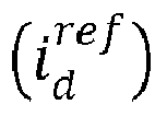
- a method of controlling a grid-connected voltage source converter, VSC, using power-synchronisation control comprises: determining a VSC current vector based on a VSC phase angle which is determined based on an integration of a power control error, determining an active power producing current component i d ref of a reference current vector based on an active power reference for the VSC, determining the reference current vector based on the active power producing current component, determining a damping component based on a virtual damping resistance, the reference current vector and the VSC current vector, determining a voltage vector based on a VSC voltage magnitude and the damping component, and controlling the VSC based on the voltage vector.
- a robust closed-loop system By determining the active power producing current component i d ref based on the active power reference, a robust closed-loop system maybe provided for strong grids.
- the improvement compared to traditional power-synchronisation control is gained by a pole-zero cancellation that reduces the closed active-power control loop dynamics from a third-order system to a first-order system. Additionally, the damping performance for weak grids is maintained, or even improved, compared to traditional PSC.
- robust control irrespective of SCR may be provided.
- the method may thus advantageously be used in both weak and strong grids.
- the active power control error is the difference between an active power output from the VSC and the active power reference.
- the VSC voltage magnitude is typically predetermined and can be set to be constant. Alternatively the VSC voltage magnitude can be set to change dynamically, using a specific control loop for this purpose.
- the active power producing current component is determined based on setting it proportional to the active power reference.
- the active power producing current component may be the real value current component of the reference current vector in the dq-frame.
- One embodiment comprises transforming the voltage vector to a stationary frame using the VSC phase angle to obtain a transformed voltage vector, wherein the controlling involves using the transformed voltage vector to control the VSC.
- the stationary frame may be the ⁇ -frame.
- One embodiment comprises determining a reactive power producing current component of the reference current vector using low-pass filtering of an imaginary part of the VSC current vector, wherein the reference current vector is further determined based on the reactive power producing current component.
- the reactive power producing current component may be the imaginary value current component of the reference current vector in the dq-frame.
- the damping component is determined by determining a current error vector based on the reference current vector and the VSC current vector, and multiplying the virtual damping resistance with the current error vector.
- the current error vector may be determined by subtracting the reference current vector from the VSC current vector or subtracting the VSC current vector from the reference current vector.
- the VSC current vector is determined by transforming a stationary VSC current vector, obtained by measurement, using the VSC phase angle.
- a computer program comprising computer code which when executed by processing circuitry of a control system causes the control system to perform the method according to the first aspect.
- a control system for controlling a grid-connected voltage source converter, VSC, usingpower-synchronisation control
- the control system comprises: a storage medium comprising computer code, and processing circuitry, wherein when the computer code is executed by the processing circuitry, the control system is configured to: determine a VSC current vector based on a VSC phase angle which is determined based on an integration of a power control error, determine an active power producing current component of a reference current vector based on an active power reference for the VSC, determine the reference current vector based on the active power producing current component, determine a damping component based on a virtual damping resistance, the reference current vector and the VSC current vector, determine a voltage vector based on a VSC voltage magnitude and the damping component, and control the VSC based on the voltage vector.
- control system is configured to determine the active power producing current component based on setting it proportional to the active power reference.
- the processing circuitry is configured to transform the voltage vector to a stationary frame using the VSC phase angle to obtain a transformed voltage vector, wherein the control system is configured to control the VSC using the transformed voltage vector.
- control system is configured to determine a reactive power producing current component of the reference current vector using low-pass filtering of an imaginary part of the VSC current vector, wherein the reference current vector is further determined based on the reactive power producing current component.
- the damping component is determined by determining a current error vector based on the reference current vector and the VSC current vector, and by multiplying the virtual damping resistance with the current error vector.
- Fig. 1 shows an example of a control system 1 for controlling a grid-connected VSC using power-synchronisation control.
- the control system 1 comprises processing circuitry 3 and a storage medium 5.
- the processing circuitry 3 may use any combination of one or more of a suitable central processing unit (CPU), multiprocessor, microcontroller, digital signal processor (DSP), application specific integrated circuit (ASIC), field programmable gate arrays (FPGA) etc., capable of executing any herein disclosed operations concerning VSC control.
- CPU central processing unit
- DSP digital signal processor
- ASIC application specific integrated circuit
- FPGA field programmable gate arrays
- the storage medium 5 may for example be embodied as a memory, such as a random access memory (RAM), a read-only memory (ROM), an erasable programmable read-only memory (EPROM), or an electrically erasable programmable read-only memory (EEPROM) and more particularly as a non-volatile storage medium of a device in an external memory such as a USB (Universal Serial Bus) memory or a Flash memory, such as a compact Flash memory.
- RAM random access memory
- ROM read-only memory
- EPROM erasable programmable read-only memory
- EEPROM electrically erasable programmable read-only memory
- Fig. 2 shows a grid-connected VSC 7.
- the control system 1 is configured to control the VSC 7.
- the VSC 7 is connected to an AC network 9 and to a DC network 11.
- An inductor 13 with inductance L symbolises the inductance of the grid.
- the inductance Li s the sum of the filter inductance of the VSC 7 and the grid inductance.
- a virtual damping resistance R a also known as "active resistance” or “virtual resistance", which does not form part of the actual grid is also shown.
- the virtual damping resistance R a is used in the present method to increase the robustness of the control, in particular to provide damping in the event of transients.
- the control system 1 is configured to obtain electric parameters from the grid.
- electric parameters may for example be VSC currents to obtain a measured stationary VSC current vector i s and VSC voltages to obtain a measured stationary VSC voltage vector v s , used for determining an active power output P.
- stationary is meant that the electric parameter in question is in a stationary frame.
- a current/voltage meter may for example be used to measure these parameters.
- Fig. 3 depicts a block diagram showing an example of the control of the grid-connected VSC 7 by means of the control system 1, using power-synchronisation control.
- the blocks of the block diagram are implemented by the processing circuitry 3 as hardware and/or software.
- a power control error is determined.
- the power control error is determined by the difference between the active power output P and an active power reference P ref for the VSC 7.
- the power control error is multiplied with a power control gain K p , to obtain a scaled power control error.
- the power control gain K p is a constant.
- the power control gain K p typically has unitrad/(Ws) or similar, generally based on how the system is normalised.
- an angular frequency ⁇ 1 is added to the scaled power control error.
- the angular frequency ⁇ 1 is the angular frequency with which the space vectors of e.g. the measured stationary VSC current vector i s rotate in the stationary frame.
- the sum of the scaled power control error and the angular frequency ⁇ 1 is integrated. In this manner, the VSC phase angle ⁇ is obtained.
- the output from the integration block 21, i.e. the VSC phase angle ⁇ is sent to a first exponential block 22 to obtain e j ⁇ .
- the output from the integration block 21, i.e. the VSC phase angle ⁇ is also sent to a second exponentialblock 23 to obtain e -j ⁇ .
- a fourth block 25 the output from the second exponential block 23, i.e. e -j ⁇ is multiplied with the stationary VSC current vector is as obtained by measurement.
- the stationary VSC current vector is is thus transformed into a VSC current vector i in the dq-frame.
- the "s" denotes the stationary frame, in particular the ⁇ -frame.
- the imaginary part iq of the VSC current vector i in the dq-frame is separated in a separation block 27 and input to a filtering block 29
- the exemplified filtering block 29 provides a low-pass filtering of the imaginary part iq of the VSC current vector i in the dq-frame.
- the low-pass filtering of the imaginary part iq of the VSC current vector i determines the reactive power producing component i q ref of a reference current vector i ref .
- the active power reference P ref is scaled in a fifth block 31, whereby the active power producing current component i d ref of the reference current vector i ref is determined.
- the scaling factor provided by the fifth block 31 is 1/ ⁇ V, where ⁇ is a space-vector scaling constant.
- the scaling of the active power reference P ref provided in the fifth block 31 is set as the active power producing component i d ref of the reference current vector i ref .
- i d ref P ref / ⁇ V
- the reference current vector i ref may in particular be obtained in a combining block 33 where the active power producing component i d ref and the reactive power producing component i q ref are combined.
- a current error vector for the VSC current vector i in the dq-frame and the reference current vector i ref is determined.
- one of the VSC current vector i and the reference current vector i ref is subtracted from the other to obtain the current error vector.
- a damping component is determined.
- the virtual damping resistance R a is multiplied with the current error vector to obtain the damping component R a *( i - i ref ) or R a *( i ref - i ), the sign depending on the direction of the VSC current vector i.
- a voltage vector v is determined by adding the damping component and a VSC voltage magnitude V.
- the VSC voltage magnitude V can for example be selected to be constant, e.g. 1 per unit (p.u.). Alternatively, the VSC magnitude V can be selectedusing a specific control loop for this purpose.
- the voltage magnitude V is a real component in the dq-frame.
- R a *( i ref - i ) provides damping and may include a complex and a real component, the latter then being added to the real-valued voltage magnitude V in the dq-frame.
- the voltage vector v is transformed to the stationary frame, in particular the ⁇ -frame by multiplication with the output from the first exponential block 22, i.e. e j ⁇ .
- a transformed voltage vector v s Ve j ⁇ is thus obtained.
- the transformed voltage vector v s is in the ⁇ -frame.
- the transformed voltage vector v s is used for controlling the VSC 7.
- the control system 1 is thus configured to control the VSC 7 based on the transformed voltage vector v s .
- This control may for example be by means of pulse width modulation (PWM),i.e. by using PWM for switching the switches, for example insulated gate bipolar transistors (IBGTs) of the VSC 7.
- PWM pulse width modulation
- IBGTs insulated gate bipolar transistors
- Fig. 4a shows the step response for traditional power-synchronisation control in a simulation.
- the uppermost graphs shows the angle ⁇ , which is the angle difference between the VSC voltage and grid voltage, i d and iq in the middle graph are the active power producing current component and the reactive power producing current component of the VSC current vector i.
- the poor damping factor is evident.
- Fig. 4b for the corresponding simulation with the herein described control method, the response obtained from a corresponding simulation is well damped.
Landscapes
- Engineering & Computer Science (AREA)
- Power Engineering (AREA)
- Inverter Devices (AREA)
Abstract

Description
- The present disclosure generally relates to voltage source converter control.
- Power-synchronization control (PSC), also known as synchronous-machine emulating control or virtual synchronous machine, was originally invented for the control of an HVDC Light transmission where both terminals were situated in very weak ac networks. PSC is disclosed in
EP2319170 . The method is similar, but not identical, to the virtual synchronous machine. PSC can be used for any grid-connected voltage-source converter (VSC), not just HVDC. - The name PSC refers to how the method achieves synchronization to the grid; via the control of the active power. PSC therefore does not utilize a phase-locked loop (PLL). PSC is effective for connection to weak grids, with a short-circuit ratio (SCR) below 2. However, it gives a poorly damped closed-loop system for connection to a strong grid. In that case, the traditional method of vector current control (VCC) with outer loops, including a PLL, is preferable.
- In a situation where the SCR is known to vary within a wide range, including SCR< 2, there are currently two options.
- 1. Tune the PSC power-control gain on-line as a function of the SCR.
- 2. Make a switchover between PSC and VCC at a predetermined SCR.
- Neither option is desirable. The preferred situation is to have a control system that is robust to the SCR.
- In view of the above, an object of the present disclosure is to provide a method of controlling a voltage source converter which solves, or at least mitigates, the problems of the prior art.
- There is hence according to a first aspect of the present disclosure provided a method of controlling a grid-connected voltage source converter, VSC, using power-synchronisation control, wherein the method comprises: determining a VSC current vector based on a VSC phase angle which is determined based on an integration of a power control error, determining an active power producing current component

- By determining the active power producing current component

- The method may thus advantageously be used in both weak and strong grids.
- The active power control error is the difference between an active power output from the VSC and the active power reference.
- The VSC voltage magnitude is typically predetermined and can be set to be constant. Alternatively the VSC voltage magnitude can be set to change dynamically, using a specific control loop for this purpose.
- According to one embodiment the active power producing current component is determined based on setting it proportional to the active power reference.
- The active power producing current component may be the real value current component of the reference current vector in the dq-frame.
- According to one embodiment the active power producing current component


- One embodiment comprises transforming the voltage vector to a stationary frame using the VSC phase angle to obtain a transformed voltage vector, wherein the controlling involves using the transformed voltage vector to control the VSC.
- The stationary frame may be the αβ-frame.
- One embodiment comprises determining a reactive power producing current component of the reference current vector using low-pass filtering of an imaginary part of the VSC current vector, wherein the reference current vector is further determined based on the reactive power producing current component.
- The reactive power producing current component may be the imaginary value current component of the reference current vector in the dq-frame.
- According to one embodiment the damping component is determined by determining a current error vector based on the reference current vector and the VSC current vector, and multiplying the virtual damping resistance with the current error vector.
- The current error vector may be determined by subtracting the reference current vector from the VSC current vector or subtracting the VSC current vector from the reference current vector.
- According to one embodiment the VSC current vector is determined by transforming a stationary VSC current vector, obtained by measurement, using the VSC phase angle.
- There is according to a second aspect of the present disclosure provided a computer program comprising computer code which when executed by processing circuitry of a control system causes the control system to perform the method according to the first aspect.
- There is according to a third aspect of the present disclosure provided a control system for controlling a grid-connected voltage source converter, VSC, usingpower-synchronisation control, wherein the control system comprises: a storage medium comprising computer code, and processing circuitry, wherein when the computer code is executed by the processing circuitry, the control system is configured to: determine a VSC current vector based on a VSC phase angle which is determined based on an integration of a power control error, determine an active power producing current component of a reference current vector based on an active power reference for the VSC, determine the reference current vector based on the active power producing current component, determine a damping component based on a virtual damping resistance, the reference current vector and the VSC current vector, determine a voltage vector based on a VSC voltage magnitude and the damping component, and control the VSC based on the voltage vector.
- According to one embodiment the control system is configured to determine the active power producing current component based on setting it proportional to the active power reference.
- According to one embodiment the real value current component is determined by

- According to one embodiment the processing circuitry is configured to transform the voltage vector to a stationary frame using the VSC phase angle to obtain a transformed voltage vector, wherein the control system is configured to control the VSC using the transformed voltage vector.
- According to one embodiment the control system is configured to determine a reactive power producing current component of the reference current vector using low-pass filtering of an imaginary part of the VSC current vector, wherein the reference current vector is further determined based on the reactive power producing current component.
- According to one embodiment the damping component is determined by determining a current error vector based on the reference current vector and the VSC current vector, and by multiplying the virtual damping resistance with the current error vector.
- Generally, all terms used in the claims are to be interpreted according to their ordinary meaning in the technical field, unless explicitly defined otherwise herein. All references to "a/an/the element, apparatus, component, means, etc. are to be interpreted openly as referring to at least one instance of the element, apparatus, component, means, etc., unless explicitly stated otherwise.
- The specific embodiments of the inventive concept will now be described, by way of example, with reference to the accompanying drawings, in which:
-
Fig. 1 schematically shows an example of a control system for controlling a grid-connected VSC using power-synchronisation control; -
Fig. 2 schematically shows a circuit model of a grid-connected VSC controlled by the control system inFig. 1 ; -
Fig. 3 schematically depicts a block diagram showing the control of a grid-connected VSC using the herein described power-synchronisation control; - Fig. 4a shows the step response for various parameters for traditional power-synchronisation control; and
- Fig. 4b shows the corresponding step response for the same parameters as in Fig. 4a but using the control method shown in
Fig. 3 . - The inventive concept will now be described more fullyhereinafter with reference to the accompanying drawings, in which exemplifying embodiments are shown. The inventive concept may, however, be embodied in many different forms and should not be construed as limited to the embodiments set forth herein; rather, these embodiments are provided by way of example so that this disclosure will be thorough and complete, and will fully convey the scope of the inventive concept to those skilled in the art. Like numbers refer to like elements throughout the description.
-
Fig. 1 shows an example of acontrol system 1 for controlling a grid-connected VSC using power-synchronisation control. Thecontrol system 1 comprisesprocessing circuitry 3 and astorage medium 5. - The
processing circuitry 3 may use any combination of one or more of a suitable central processing unit (CPU), multiprocessor, microcontroller, digital signal processor (DSP), application specific integrated circuit (ASIC), field programmable gate arrays (FPGA) etc., capable of executing any herein disclosed operations concerning VSC control. - The
storage medium 5 may for example be embodied as a memory, such as a random access memory (RAM), a read-only memory (ROM), an erasable programmable read-only memory (EPROM), or an electrically erasable programmable read-only memory (EEPROM) and more particularly as a non-volatile storage medium of a device in an external memory such as a USB (Universal Serial Bus) memory or a Flash memory, such as a compact Flash memory. -
Fig. 2 shows a grid-connectedVSC 7. Thecontrol system 1 is configured to control theVSC 7. TheVSC 7 is connected to anAC network 9 and to aDC network 11. Aninductor 13 with inductance L symbolises the inductance of the grid. The inductance Lis the sum of the filter inductance of theVSC 7 and the grid inductance. A virtual damping resistance Ra, also known as "active resistance" or "virtual resistance", which does not form part of the actual grid is also shown. The virtual damping resistance Ra is used in the present method to increase the robustness of the control, in particular to provide damping in the event of transients. - The
control system 1 is configured to obtain electric parameters from the grid. Such electric parameters may for example be VSC currents to obtain a measured stationary VSC current vector i s and VSC voltages to obtain a measured stationary VSC voltage vector v s , used for determining an active power output P. With the term "stationary" is meant that the electric parameter in question is in a stationary frame. A current/voltage meter may for example be used to measure these parameters. -
Fig. 3 depicts a block diagram showing an example of the control of the grid-connectedVSC 7 by means of thecontrol system 1, using power-synchronisation control. The blocks of the block diagram are implemented by theprocessing circuitry 3 as hardware and/or software. - In a first block 15 a power control error is determined. The power control error is determined by the difference between the active power output P and an active power reference Pref for the
VSC 7. - In a
second block 17, the power control error is multiplied with a power control gain Kp, to obtain a scaled power control error. The power control gain Kp is a constant. The power control gain Kp typically has unitrad/(Ws) or similar, generally based on how the system is normalised. - In a
third block 19, an angular frequency ω1, is added to the scaled power control error. The angular frequency ω1 is the angular frequency with which the space vectors of e.g. the measured stationary VSC current vector i s rotate in the stationary frame. - In an
integration block 21, the sum of the scaled power control error and the angular frequency ω1 is integrated. In this manner, the VSC phase angle θ is obtained. - The output from the
integration block 21, i.e. the VSC phase angle θ is sent to a firstexponential block 22 to obtain ejθ. - The output from the
integration block 21, i.e. the VSC phase angle θ is also sent to asecond exponentialblock 23 to obtain e-jθ. - In a
fourth block 25, the output from the secondexponential block 23, i.e. e-jθ is multiplied with the stationary VSC current vector is as obtained by measurement. The stationary VSC current vector is is thus transformed into a VSC current vector i in the dq-frame. The "s" denotes the stationary frame, in particular the αβ-frame. - The imaginary part iq of the VSC current vector i in the dq-frame is separated in a
separation block 27 and input to afiltering block 29 The exemplifiedfiltering block 29 provides a low-pass filtering of the imaginary part iq of the VSC current vector i in the dq-frame. The low-pass filtering of the imaginary part iq of the VSC current vector i determines the reactive power producing component

- The active power reference Pref is scaled in a
fifth block 31, whereby the active power producing current component
fifth block 31 is 1/κV, where κ is a space-vector scaling constant. The scaling of the active power reference Pref provided in thefifth block 31 is set as the active power producing component


block 33 where the active power producing component

- In a
sixth block 35, a current error vector for the VSC current vector i in the dq-frame and the reference current vector i ref is determined. In particular, one of the VSC current vector i and the reference current vector i ref is subtracted from the other to obtain the current error vector. - In a
seventh block 37, a damping component is determined. In particular the virtual damping resistance Ra is multiplied with the current error vector to obtain the damping component Ra*(i-i ref) or Ra*(i ref-i), the sign depending on the direction of the VSC current vector i. - In an
eighth block 39, a voltage vector v is determined by adding the damping component and a VSC voltage magnitude V. Thus, the voltage vector v=V+ Ra*(i-i ref), or alternatively V + Ra*(i ref-i) is obtained. The VSC voltage magnitude V can for example be selected to be constant, e.g. 1 per unit (p.u.). Alternatively, the VSC magnitude V can be selectedusing a specific control loop for this purpose. The voltage magnitude V is a real component in the dq-frame. The voltage vector v=V + Ra*(i ref-i) is a real number in stationary state, because then i ref-i=0. During transients Ra*(i ref-i) provides damping and may include a complex and a real component, the latter then being added to the real-valued voltage magnitude V in the dq-frame. - In a
ninth block 41, the voltage vector v is transformed to the stationary frame, in particular the αβ-frame by multiplication with the output from the firstexponential block 22, i.e. ejθ. A transformed voltage vector v s=Vejθ is thus obtained. The transformed voltage vector v s is in the αβ-frame. - The transformed voltage vector v s is used for controlling the
VSC 7. Thecontrol system 1 is thus configured to control theVSC 7 based on the transformed voltage vector v s. This control may for example be by means of pulse width modulation (PWM),i.e. by using PWM for switching the switches, for example insulated gate bipolar transistors (IBGTs) of theVSC 7. - Fig. 4a shows the step response for traditional power-synchronisation control in a simulation. In this simulation, the grid is strong with the inductance L=0.2 p.u., and the power control gain Kp and the virtual damping resistance Ra are set equal, in this example Kp=Ra=0.2 p.u. A step in the output power, on the dc side of the dc link of the
VSC 7 from 0 to 0.5 p.u. is made at t=0.2 s, followed by a step to -0.5 p.u. at t=0.6 s. The uppermost graphs shows the angle δ, which is the angle difference between the VSC voltage and grid voltage, id and iq in the middle graph are the active power producing current component and the reactive power producing current component of the VSC current vector i. The poor damping factor is evident. By contrast, referring to Fig. 4b, for the corresponding simulation with the herein described control method, the response obtained from a corresponding simulation is well damped. - The inventive concept has mainly been described above with reference to a few examples. However, as is readily appreciated by a person skilled in the art, other embodiments than the ones disclosed above are equallypossible within the scope of the inventive concept, as defined by the appended claims.
Claims (14)
- A method of controlling a grid-connected voltage source converter, VSC (7), using power-synchronisation control, wherein the method comprises:determining a VSC current vector (i) based on a VSC phase angle (θ) which is determined based on an integration of a power control error,determining an active power producing current component
 determining the reference current vector (i ref) based on the active power producing current component
 determining a damping component based on a virtual damping resistance (Ra), the reference current vector (i ref) and the VSC current vector (i),determining a voltage vector (v) based on a VSC voltage magnitude (V) and the damping component, andcontrolling the VSC (7) based on the voltage vector (v).
 - The method as claimed in claim 1, wherein the active power producing current component

- The method as claimed in claim 2, wherein the active power producing current component


- The method as claimed in any of the preceding claims, comprising transforming the voltage vector (v) to a stationary frame using the VSC phase angle (θ) to obtain a transformed voltage vector (v s), wherein the controlling involves using the transformed voltage vector (v s) to control the VSC (7).
- The method as claimed in any of the preceding claims, comprising determining a reactive power producing current component


- The method as claimed in any of the preceding claims, wherein the damping component is determined by determining a current error vector based on the reference current vector (i ref) and the VSC current vector (i), and multiplying the virtual damping resistance with the current error vector.
- The method as claimed in any of the preceding claims, wherein the VSC current vector (i) is determined by transforming a stationary VSC current vector (i s), obtained by measurement,usingthe VSC phase angle (θ).
- A computer program comprising computer code which when executed by processing circuitry (3) of a control system (1) causes the control system (1) to perform the method as claimed in any of claims 1-7.
- A control system (1) for controlling a grid-connected voltage source converter, VSC (7), using power-synchronisation control, wherein the control system (1) comprises:a storage medium (5) comprising computer code, andprocessing circuitry (3),wherein when the computer code is executed by the processing circuitry (3), the control system (1) is configured to:determine a VSC current vector (i) based on a VSC phase angle (θ) which is determined based on an integration of a power control error,determine an active power producing current component
 determine the reference current vector (i ref) based on the active power producing current component
 determine a damping component based on a virtual damping resistance (Ra), the reference current vector (i ref) and the VSC current vector (i),determine a voltage vector (v) based on a VSC voltage magnitude (V) and the damping component, andcontrol the VSC (7) based on the voltage vector (v).
 - The control system (1) as claimed in claim 9, wherein the control system (1) is configured to determine the active power producing current component

- The control system (1) as claimed in claim 10, wherein the active power producing current component


- The control system (1) as claimed in any of claims 9-11, wherein the processing circuitry (3) is configured to transform the voltage vector (v) to a stationary frame using the VSC phase angle (θ) to obtain a transformed voltage vector (v s), wherein the control system (1) is configured to control the VSC (7) using the transformed voltage vector (v s).
- The control system (1) as claimed in any of claims 9-12, wherein the control system (1) is configured to determine a reactive power producing current component


- The control system (1) as claimed in any of claims 9-13, wherein the damping component is determined by determining a current error vector based on the reference current vector (i ref) and the VSC current vector (i), and by multiplying the virtual damping resistance with the current error vector.
Priority Applications (3)
| Application Number | Priority Date | Filing Date | Title |
|---|---|---|---|
| EP17202372.3A EP3487060A1 (en) | 2017-11-17 | 2017-11-17 | Method and control system for controlling a voltage source converter using power-synchronisation control |
| US16/190,926 US10389129B2 (en) | 2017-11-17 | 2018-11-14 | Method and control system for controlling a voltage source converter using power-synchronization control |
| CN201811364006.1A CN109802442B (en) | 2017-11-17 | 2018-11-16 | Method and control system for controlling a voltage source converter using power synchronous control |
Applications Claiming Priority (1)
| Application Number | Priority Date | Filing Date | Title |
|---|---|---|---|
| EP17202372.3A EP3487060A1 (en) | 2017-11-17 | 2017-11-17 | Method and control system for controlling a voltage source converter using power-synchronisation control |
Publications (1)
| Publication Number | Publication Date |
|---|---|
| EP3487060A1 true EP3487060A1 (en) | 2019-05-22 |
Family
ID=60387937
Family Applications (1)
| Application Number | Title | Priority Date | Filing Date |
|---|---|---|---|
| EP17202372.3A Pending EP3487060A1 (en) | 2017-11-17 | 2017-11-17 | Method and control system for controlling a voltage source converter using power-synchronisation control |
Country Status (3)
| Country | Link |
|---|---|
| US (1) | US10389129B2 (en) |
| EP (1) | EP3487060A1 (en) |
| CN (1) | CN109802442B (en) |
Cited By (1)
| Publication number | Priority date | Publication date | Assignee | Title |
|---|---|---|---|---|
| CN110112900A (en) * | 2019-06-25 | 2019-08-09 | 国网湖南省电力有限公司 | The quick suppressing method of electric current based on virtual impedance |
Families Citing this family (10)
| Publication number | Priority date | Publication date | Assignee | Title |
|---|---|---|---|---|
| EP3534522B1 (en) * | 2018-02-28 | 2021-04-28 | ABB Schweiz AG | Method and control system for controlling a voltage source converter using power-synchronisation control |
| CN109659969B (en) * | 2019-02-15 | 2019-11-15 | 四川大学 | A method for judging and controlling dynamic stability of flexible direct current transmission |
| US10587214B1 (en) * | 2019-03-22 | 2020-03-10 | Hamilton Sundstrand Corporation | Matrix converter operation in current control mode with regulation of output voltage vector |
| CN110346649B (en) * | 2019-07-09 | 2021-07-09 | 国网河北省电力有限公司衡水供电分公司 | A method for determining the capacity of an energy storage buffer |
| US11456645B2 (en) | 2020-12-10 | 2022-09-27 | General Electric Renovables Espana, S.L. | System and method for operating an asynchronous inverter-based resource as a virtual synchronous machine with storage |
| US11671039B2 (en) | 2020-12-10 | 2023-06-06 | General Electric Renovables Espana, S.L. | System and method for operating an asynchronous inverter-based resource as a virtual synchronous machine to provide grid-forming control thereof |
| WO2023131414A1 (en) | 2022-01-07 | 2023-07-13 | Huawei Digital Power Technologies Co., Ltd. | Active power conversion apparatus, system, and method for use in active power conversion apparatus |
| US12081162B2 (en) | 2022-08-25 | 2024-09-03 | General Electric Renovables Espana, S.L. | System and method for operating a renewable energy source in grid-forming mode (GFM) as a virtual synchronous machine (VSM) with damper winding emulation |
| CN117200330B (en) * | 2023-08-31 | 2025-11-28 | 国网北京市电力公司 | Power synchronization control method, device, storage medium and equipment |
| CN118713123B (en) * | 2024-08-29 | 2024-12-06 | 湖北工业大学 | Method and system for enhancing power recovery of PV-ESS-VSG system |
Citations (2)
| Publication number | Priority date | Publication date | Assignee | Title |
|---|---|---|---|---|
| EP2319170A1 (en) | 2008-08-26 | 2011-05-11 | ABB Technology AG | Control of a voltage source converter using synchronous machine emulation |
| SE1200606A1 (en) * | 2012-10-08 | 2012-10-10 | Abb Research Ltd | Power synchronization control of a single-phase voltage-rigid inverter |
Family Cites Families (8)
| Publication number | Priority date | Publication date | Assignee | Title |
|---|---|---|---|---|
| EP0571642B1 (en) * | 1992-05-18 | 1998-01-14 | Siemens Aktiengesellschaft | Method and device for generating a synchronisation signal for a control unit of a controlled valve of a series compensator |
| US7319307B2 (en) * | 2005-12-16 | 2008-01-15 | General Electric Company | Power balancing of multiple synchronized generators |
| ES2402499B1 (en) * | 2011-02-28 | 2013-11-26 | Abengoa Solar New Technologies S.A. | VIRTUAL ELECTROMECHANICAL CHARACTERISTICS CONTROLLER FOR STATIC POWER CONVERTERS. |
| JP5618023B1 (en) * | 2013-06-11 | 2014-11-05 | 住友電気工業株式会社 | Inverter device |
| BR102013025443B1 (en) * | 2013-09-26 | 2021-11-03 | José Félix Manfredi | PRECISION ANALYTICAL PUMP |
| EP3086432B1 (en) * | 2015-04-23 | 2018-07-18 | GE Energy Power Conversion Technology Ltd | Power distribution systems |
| CN105703381A (en) | 2015-11-27 | 2016-06-22 | 华北电力大学 | Power damping synchronization control method suitable for VSC-HVDC connection extremely-weak AC power grid |
| CN105914778B (en) * | 2016-04-19 | 2019-02-05 | 东南大学 | Multi-loop control method of microgrid inverter based on virtual synchronous generator |
-
2017
- 2017-11-17 EP EP17202372.3A patent/EP3487060A1/en active Pending
-
2018
- 2018-11-14 US US16/190,926 patent/US10389129B2/en active Active
- 2018-11-16 CN CN201811364006.1A patent/CN109802442B/en active Active
Patent Citations (2)
| Publication number | Priority date | Publication date | Assignee | Title |
|---|---|---|---|---|
| EP2319170A1 (en) | 2008-08-26 | 2011-05-11 | ABB Technology AG | Control of a voltage source converter using synchronous machine emulation |
| SE1200606A1 (en) * | 2012-10-08 | 2012-10-10 | Abb Research Ltd | Power synchronization control of a single-phase voltage-rigid inverter |
Non-Patent Citations (2)
| Title |
|---|
| LIDONG ZHANG ET AL: "Power-Synchronization Control of Grid-Connected Voltage-Source Converters", IEEE TRANSACTIONS ON POWER SYSTEMS, IEEE SERVICE CENTER, PISCATAWAY, NJ, US, vol. 25, no. 2, 1 May 2010 (2010-05-01), pages 809 - 820, XP011297020, ISSN: 0885-8950 * |
| ZHANG WEIYI ET AL: "Frequency support characteristics of grid-interactive power converters based on the synchronous power controller", IET RENEWABLE POWER GENERATION, THE INSTITUTION OF ENGINEERING AND TECHNOLOGY, MICHAEL FARADAY HOUSE, SIX HILLS WAY, STEVENAGE, HERTS. SG1 2AY, UK, vol. 11, no. 4, 15 March 2017 (2017-03-15), pages 470 - 479, XP006061208, ISSN: 1752-1416, DOI: 10.1049/IET-RPG.2016.0557 * |
Cited By (1)
| Publication number | Priority date | Publication date | Assignee | Title |
|---|---|---|---|---|
| CN110112900A (en) * | 2019-06-25 | 2019-08-09 | 国网湖南省电力有限公司 | The quick suppressing method of electric current based on virtual impedance |
Also Published As
| Publication number | Publication date |
|---|---|
| US20190157870A1 (en) | 2019-05-23 |
| US10389129B2 (en) | 2019-08-20 |
| CN109802442A (en) | 2019-05-24 |
| CN109802442B (en) | 2023-06-02 |
Similar Documents
| Publication | Publication Date | Title |
|---|---|---|
| EP3487060A1 (en) | Method and control system for controlling a voltage source converter using power-synchronisation control | |
| US10770900B2 (en) | Method and control system for controlling a voltage source converter using power-synchronization control | |
| Abusara et al. | Improved droop control strategy for grid-connected inverters | |
| EP3059848B1 (en) | Systems and methods to optimize active current sharing of parallel power converters | |
| EP4362306B1 (en) | Control device and power conversion device | |
| EP3220529B1 (en) | Method for controlling three phase equivalent voltage of multilevel inverter | |
| Senini et al. | Analysis and design of a multiple-loop control system for a hybrid active filter | |
| CN116885781A (en) | A grid-connected converter operating mode switching method and system | |
| EP3506474B1 (en) | Single-phase converter control method and apparatus | |
| US20100253269A1 (en) | Method for operating a rotating electric machine | |
| CN106546851A (en) | A kind of stable control method and device of MMC converter valve operating tests circuit | |
| US12334738B2 (en) | Power conversion device and estimation device | |
| CN104242250B (en) | The relay protecting method and system of a kind of modularization multi-level converter | |
| EP2955812B1 (en) | Power transmission network | |
| Marin et al. | Stability analysis of a droop-controlled grid-connected VSC | |
| CN116009424A (en) | SVG-based power system simulation device, simulation testing method and system | |
| Singh et al. | A conflict in control strategy of voltage and current controllers in Multi-Modular single-phase UPS inverters system | |
| Shah et al. | Impedance-based Stability Characterization of Extended Finite Control Set MPC under Realistic Switching Constraints | |
| Kouchaki et al. | 5 kW bidirectional grid-connected drive using silicon-carbide switches: Control | |
| CN119631287A (en) | Voltage control device and voltage control method | |
| CN118739406A (en) | Grid-connected converter AC voltage control parameter design method and related device | |
| DE112024000246T5 (en) | Electrical power conversion device | |
| CN121216857A (en) | General voltage control methods, devices and equipment applicable to grid-type converters | |
| Raghavan et al. | Simulation and analysis of power synchronization control for voltage source inverter | |
| El-Deeb et al. | Discrete time domain analysis and optimal design of stationary frame AC current controllers with active damped LCL Filter for high power applications |
Legal Events
| Date | Code | Title | Description |
|---|---|---|---|
| PUAI | Public reference made under article 153(3) epc to a published international application that has entered the european phase |
Free format text: ORIGINAL CODE: 0009012 |
|
| STAA | Information on the status of an ep patent application or granted ep patent |
Free format text: STATUS: THE APPLICATION HAS BEEN PUBLISHED |
|
| AK | Designated contracting states |
Kind code of ref document: A1 Designated state(s): AL AT BE BG CH CY CZ DE DK EE ES FI FR GB GR HR HU IE IS IT LI LT LU LV MC MK MT NL NO PL PT RO RS SE SI SK SM TR |
|
| AX | Request for extension of the european patent |
Extension state: BA ME |
|
| STAA | Information on the status of an ep patent application or granted ep patent |
Free format text: STATUS: REQUEST FOR EXAMINATION WAS MADE |
|
| STAA | Information on the status of an ep patent application or granted ep patent |
Free format text: STATUS: EXAMINATION IS IN PROGRESS |
|
| 17P | Request for examination filed |
Effective date: 20191122 |
|
| RBV | Designated contracting states (corrected) |
Designated state(s): AL AT BE BG CH CY CZ DE DK EE ES FI FR GB GR HR HU IE IS IT LI LT LU LV MC MK MT NL NO PL PT RO RS SE SI SK SM TR |
|
| 17Q | First examination report despatched |
Effective date: 20200102 |
|
| GRAP | Despatch of communication of intention to grant a patent |
Free format text: ORIGINAL CODE: EPIDOSNIGR1 |
|
| STAA | Information on the status of an ep patent application or granted ep patent |
Free format text: STATUS: GRANT OF PATENT IS INTENDED |
|
| INTG | Intention to grant announced |
Effective date: 20201211 |
|
| GRAJ | Information related to disapproval of communication of intention to grant by the applicant or resumption of examination proceedings by the epo deleted |
Free format text: ORIGINAL CODE: EPIDOSDIGR1 |
|
| STAA | Information on the status of an ep patent application or granted ep patent |
Free format text: STATUS: EXAMINATION IS IN PROGRESS |
|
| INTC | Intention to grant announced (deleted) | ||
| RAP3 | Party data changed (applicant data changed or rights of an application transferred) |
Owner name: ABB SCHWEIZ AG |
|
| GRAP | Despatch of communication of intention to grant a patent |
Free format text: ORIGINAL CODE: EPIDOSNIGR1 |
|
| STAA | Information on the status of an ep patent application or granted ep patent |
Free format text: STATUS: GRANT OF PATENT IS INTENDED |
|
| INTG | Intention to grant announced |
Effective date: 20210621 |
|
| GRAJ | Information related to disapproval of communication of intention to grant by the applicant or resumption of examination proceedings by the epo deleted |
Free format text: ORIGINAL CODE: EPIDOSDIGR1 |
|
| STAA | Information on the status of an ep patent application or granted ep patent |
Free format text: STATUS: EXAMINATION IS IN PROGRESS |
|
| INTC | Intention to grant announced (deleted) | ||
| APBK | Appeal reference recorded |
Free format text: ORIGINAL CODE: EPIDOSNREFNE |
|
| APBN | Date of receipt of notice of appeal recorded |
Free format text: ORIGINAL CODE: EPIDOSNNOA2E |
|
| APAF | Appeal reference modified |
Free format text: ORIGINAL CODE: EPIDOSCREFNE |
|
| APBR | Date of receipt of statement of grounds of appeal recorded |
Free format text: ORIGINAL CODE: EPIDOSNNOA3E |
|
| APAF | Appeal reference modified |
Free format text: ORIGINAL CODE: EPIDOSCREFNE |
|
| APAF | Appeal reference modified |
Free format text: ORIGINAL CODE: EPIDOSCREFNE |
|
| APBT | Appeal procedure closed |
Free format text: ORIGINAL CODE: EPIDOSNNOA9E |
|
| GRAP | Despatch of communication of intention to grant a patent |
Free format text: ORIGINAL CODE: EPIDOSNIGR1 |
|
| STAA | Information on the status of an ep patent application or granted ep patent |
Free format text: STATUS: GRANT OF PATENT IS INTENDED |
|
| INTG | Intention to grant announced |
Effective date: 20260216 |