EP3487042A1 - Electric motor - Google Patents
Electric motor Download PDFInfo
- Publication number
- EP3487042A1 EP3487042A1 EP18206290.1A EP18206290A EP3487042A1 EP 3487042 A1 EP3487042 A1 EP 3487042A1 EP 18206290 A EP18206290 A EP 18206290A EP 3487042 A1 EP3487042 A1 EP 3487042A1
- Authority
- EP
- European Patent Office
- Prior art keywords
- cooling fins
- ring
- stator assembly
- set forth
- electric motor
- Prior art date
- Legal status (The legal status is an assumption and is not a legal conclusion. Google has not performed a legal analysis and makes no representation as to the accuracy of the status listed.)
- Granted
Links
Images



Classifications
-
- H—ELECTRICITY
- H02—GENERATION; CONVERSION OR DISTRIBUTION OF ELECTRIC POWER
- H02K—DYNAMO-ELECTRIC MACHINES
- H02K1/00—Details of the magnetic circuit
- H02K1/06—Details of the magnetic circuit characterised by the shape, form or construction
- H02K1/12—Stationary parts of the magnetic circuit
- H02K1/20—Stationary parts of the magnetic circuit with channels or ducts for flow of cooling medium
-
- H—ELECTRICITY
- H02—GENERATION; CONVERSION OR DISTRIBUTION OF ELECTRIC POWER
- H02K—DYNAMO-ELECTRIC MACHINES
- H02K1/00—Details of the magnetic circuit
- H02K1/06—Details of the magnetic circuit characterised by the shape, form or construction
- H02K1/12—Stationary parts of the magnetic circuit
- H02K1/14—Stator cores with salient poles
- H02K1/146—Stator cores with salient poles consisting of a generally annular yoke with salient poles
-
- H—ELECTRICITY
- H02—GENERATION; CONVERSION OR DISTRIBUTION OF ELECTRIC POWER
- H02K—DYNAMO-ELECTRIC MACHINES
- H02K5/00—Casings; Enclosures; Supports
- H02K5/04—Casings or enclosures characterised by the shape, form or construction thereof
- H02K5/18—Casings or enclosures characterised by the shape, form or construction thereof with ribs or fins for improving heat transfer
-
- H—ELECTRICITY
- H02—GENERATION; CONVERSION OR DISTRIBUTION OF ELECTRIC POWER
- H02K—DYNAMO-ELECTRIC MACHINES
- H02K5/00—Casings; Enclosures; Supports
- H02K5/04—Casings or enclosures characterised by the shape, form or construction thereof
- H02K5/20—Casings or enclosures characterised by the shape, form or construction thereof with channels or ducts for flow of cooling medium
- H02K5/207—Casings or enclosures characterised by the shape, form or construction thereof with channels or ducts for flow of cooling medium with openings in the casing specially adapted for ambient air
-
- H—ELECTRICITY
- H02—GENERATION; CONVERSION OR DISTRIBUTION OF ELECTRIC POWER
- H02K—DYNAMO-ELECTRIC MACHINES
- H02K7/00—Arrangements for handling mechanical energy structurally associated with dynamo-electric machines, e.g. structural association with mechanical driving motors or auxiliary dynamo-electric machines
- H02K7/14—Structural association with mechanical loads, e.g. with hand-held machine tools or fans
-
- H—ELECTRICITY
- H02—GENERATION; CONVERSION OR DISTRIBUTION OF ELECTRIC POWER
- H02K—DYNAMO-ELECTRIC MACHINES
- H02K9/00—Arrangements for cooling or ventilating
- H02K9/02—Arrangements for cooling or ventilating by ambient air flowing through the machine
- H02K9/04—Arrangements for cooling or ventilating by ambient air flowing through the machine having means for generating a flow of cooling medium
- H02K9/06—Arrangements for cooling or ventilating by ambient air flowing through the machine having means for generating a flow of cooling medium with fans or impellers driven by the machine shaft
-
- H—ELECTRICITY
- H02—GENERATION; CONVERSION OR DISTRIBUTION OF ELECTRIC POWER
- H02K—DYNAMO-ELECTRIC MACHINES
- H02K9/00—Arrangements for cooling or ventilating
- H02K9/14—Arrangements for cooling or ventilating wherein gaseous cooling medium circulates between the machine casing and a surrounding mantle
-
- H—ELECTRICITY
- H02—GENERATION; CONVERSION OR DISTRIBUTION OF ELECTRIC POWER
- H02K—DYNAMO-ELECTRIC MACHINES
- H02K9/00—Arrangements for cooling or ventilating
- H02K9/22—Arrangements for cooling or ventilating by solid heat conducting material embedded in, or arranged in contact with, the stator or rotor, e.g. heat bridges
- H02K9/227—Heat sinks
-
- H—ELECTRICITY
- H02—GENERATION; CONVERSION OR DISTRIBUTION OF ELECTRIC POWER
- H02K—DYNAMO-ELECTRIC MACHINES
- H02K1/00—Details of the magnetic circuit
- H02K1/06—Details of the magnetic circuit characterised by the shape, form or construction
- H02K1/12—Stationary parts of the magnetic circuit
- H02K1/16—Stator cores with slots for windings
-
- H—ELECTRICITY
- H02—GENERATION; CONVERSION OR DISTRIBUTION OF ELECTRIC POWER
- H02K—DYNAMO-ELECTRIC MACHINES
- H02K2213/00—Specific aspects, not otherwise provided for and not covered by codes H02K2201/00 - H02K2211/00
- H02K2213/12—Machines characterised by the modularity of some components
-
- H—ELECTRICITY
- H02—GENERATION; CONVERSION OR DISTRIBUTION OF ELECTRIC POWER
- H02K—DYNAMO-ELECTRIC MACHINES
- H02K3/00—Details of windings
- H02K3/04—Windings characterised by the conductor shape, form or construction, e.g. with bar conductors
- H02K3/12—Windings characterised by the conductor shape, form or construction, e.g. with bar conductors arranged in slots
Definitions
- the present disclosure relates to an electric motor, and more particularly, to a stator assembly that can cool an electric motor.
- Traditional electric motors may include a stator, a rotor, and an aluminum frame with cooling fins located at an exterior of the frame.
- the cooling fins are adapted to dissipate heat generated in the electric motor due to electromagnetic losses both in the copper windings and laminated steel core (i.e., hysteresis and eddy current).
- the cooling fins may dissipate the heat via natural and/or forced convection depending upon the design of the motor.
- Traditional manufacturing techniques include machining of an aluminum structure into straight fins and then integrating (e.g., shrink fit) the structure with the stator at the outer diameter surface. Improvements in manufacturing techniques, versatility in fin design, and optimizing cooling capability are desirable.
- a stator assembly of an electric motor includes a plurality of ring structures centered to an axis, each of the plurality of ring structures including a ring and a plurality of cooling fins projecting radially from and spaced circumferentially about the ring, wherein each of the plurality of ring structures is disposed axially adjacent to another one of the plurality of ring structures.
- the stator assembly includes electrical windings disposed radially inward from the plurality of ring structures.
- each one of the plurality of cooling fins lies within an imaginary plane containing the axis.
- the plurality of cooling fins of a first ring structure of the plurality of cooling fins are circumferentially offset from the plurality of cooling fins of an adjacent ring structure of the plurality of ring structures.
- the plurality of cooling fins are helical.
- the plurality of cooling fins include a first plurality of helical cooling fins angled in a first direction and a second plurality of helical cooling fins angled in an opposite direction.
- the first plurality of helical cooling fins is axially adjacent to and circumferentially offset from the second plurality of helical cooling fins.
- the first plurality of helical cooling fins is axially adjacent to and circumferentially aligned to the second plurality of helical cooling fins.
- An electric motor includes a rotor adapted for rotation about an axis; and a stator assembly surrounding the rotor.
- the stator assembly includes windings; a first ring structure disposed radially outward from and concentric to the rotor, the first ring structure including a first ring and a first plurality of cooling fins spaced circumferentially about and projecting radially from the first ring; and a second ring structure disposed radially outward from and concentric to the rotor, the second ring structure including a second ring and a second plurality of cooling fins spaced circumferentially about and projecting radially from the second ring, wherein the first ring structure is axially adjacent to the second ring structure.
- the electric motor includes a fan adapted to rotate with the rotor and configured to induce airflow over the first and second plurality of cooling fins.
- the first and second ring structures are part of a stator assembly.
- the electric motor includes an external housing, wherein the first and second ring structures are an integral part of the housing.
- each one of the first plurality of cooling fins include a first forward edge and an opposite first rearward edge
- each one of the second plurality of cooling fins include a second forward edge and an opposite second rearward edge
- the first forward edge is circumferentially aligned to the first rearward edge
- the second forward edge is circumferentially aligned to the second rearward edge
- the first forward edge is circumferentially aligned and axially adjacent to the second rearward edge.
- the first forward edge is axially adjacent to and circumferentially offset from the second rearward edge.
- the first and second plurality of cooling fins are helical.
- each one of the first plurality of cooling fins include a first forward edge and an opposite first rearward edge
- each one of the second plurality of cooling fins include a second forward edge and an opposite second rearward edge
- the first forward edge is circumferentially offset from the first rearward edge
- the second forward edge is circumferentially offset from the second rearward edge
- each one of at least one of the first and second plurality of cooling fins is pin-shaped.
- each one of at least one of the first and second plurality of cooling fins is shaped like an air-foil.
- the stator assembly includes an index feature carried between the first and second rings for circumferentially aligning the first ring to the second ring
- an electric motor 20 is illustrated as one, non-limiting, embodiment of the present disclosure.
- the illustrated electric motor 20 includes a rotor 22 adapted to rotate about a rotation axis A, a stator assembly 24, a rotating shaft 26, bearings 28, a cooling fan 30, a fan cage 32, a terminal box 34, and other components.
- the shaft 26 is centered to the axis A and may be fixed to the rotor 22, such that the rotor 22 and the shaft 26 rotate together as one piece.
- the stator assembly 24 is generally located radially outward from the rotor 22 and shaft 26, and is generally stationary during operation of the electric motor 20.
- the bearings 28 are adapted to provide structural support and minimize friction between the rotating shaft 26 and the stationary stator assembly 24.
- the bearings 28 may be located axially between, and supported by, respective, opposite, end portions 36, 38 of the rotating shaft 26 and the stator assembly 24.
- the end portions 36, 38 may project from opposite, axial, ends of the rotor 22.
- End portion 36 may be attached to the cooling fan 30 for rotation of the fan, and end portion 38 may be engaged to any variety of external devices (not shown) adapted to be driven by the electric motor 20.
- the stator assembly 24 may include stator windings 40, and an external housing or casing 42.
- the electrical windings 40 are generally located radially inward from the casing 42, and may be generally supported by and fixed to, the casing 42.
- the casing 42 may include opposite end segments 44, 46, and a mid-segment 48.
- the mid-segment 48 may be cylindrical, and/or may be circumferentially continuous, and spans axially between the end segments 44, 46.
- Each end segment 44, 46 may span radially between the shaft 26 and the mid-segment 48, and may support a respective bearing 28.
- the terminal box 34 may be attached to an external surface of the mid-segment 48 for facilitating an electrical connection between the stator windings 40 and an external power source (not shown).
- the fan cage 32 facilitates protection of the fan 30, and may provide a safety function by preventing contact of the rotating fan with a person.
- the cooling fan 30 may generally be axially located between the end segment 44 of the external casing 42 and the fan cage 32. In one embodiment, the fan cage 32 is attached to the end segment 44 of the casing 42.
- the mid-segment 48 of the external casing 42 may include a plurality of ring structures 50 axially aligned side-by-side.
- Each ring structure 50 may include a base ring 52 and a plurality of cooling fins 54.
- the cooling fins 54 may project radially outward from the ring 52, and may be circumferentially distributed about the ring.
- Each fin 54 may include an axially forward edge 56 and a rearward edge 58.
- the edges 56, 58 may substantially project radially outward from the ring 52.
- Each fin 54 may further include opposite facing surfaces 60, 62 each substantially spanning axially between the edges 56, 58. With respect to the direction of rotation (see arrow 64 in FIG.
- each fin 54 may generally lie within a respective, imaginary, plane that contains the axis A. That is, fin 54 may span axially and radially, but may not be angled, or may not be twisted, in a circumferential direction.
- Each base ring 52 may include an index feature 65 configured to circumferentially align the base ring 52 to the next, axially adjacent base ring.
- the index feature 65 may include an axially projecting tab 65A adapted to project into a recess 65B of the index feature 65 and in the adjacent base ring.
- the index feature 65 may also prevent circumferential misalignment of the adjacent base rings 52, and thus misalignment of the respective, axially adjacent, fins 54.
- the fins 54 of a first ring structure 50 may be circumferentially offset from the fins 54 of the next adjacent ring structure.
- the plurality of ring structures 50 may include a multitude of axially alternating ring structures 50A, 50B. Ring structure 50A may be axially adjacent to and disposed between two ring structures 50B, and so on.
- the fins 54 of ring structure 50A may be circumferentially aligned with one-another, and the fins 54 of the ring structure 50B may be circumferentially aligned with one-another.
- the fins 54 of ring structure 50A may be circumferentially centered between adjacent fins 54 of the axially adjacent ring structure 50B. This pattern may generally repeat itself throughout the plurality of ring structures 50.
- the ring structures 50A, 50B may generally be the same, but may be orientated differently during assembly of the stator assembly 24.
- the number of ring structures 50 used in any one application of a motor 20 may be dependent upon the motor itself and/or application and environment of use. It is contemplated and understood that one ring structure type may be applied to a variety of electric motors thereby optimizing motor design versatility and reducing manufacturing and part distribution costs.
- the fan 30 produces a flow of cooling air (see arrow 66 in FIG. 2 ) through the ring structures 50 of the stator assembly 24.
- the flow of air may first impinge upon the rearward edges 58 of the offset fins 54 of the first ring structure 50A before flowing past the associated fin surfaces 60, 62, then impinging the rearward edges 58 of the fins 54 of the next ring structure 50B, and so on.
- the impingement of cooling air against the exposed edges 58 causes an air flow turbulence that increases heat transfer, thereby improving the cooling capability of the fins.
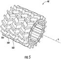
- the ring structure 50' may include a plurality of fins 54' each having an axially forward edge 56' and a rearward edge 58'.
- the edges 56', 58' may substantially project radially outward from the ring 52'.
- Each fin 54' may further include opposite facing surfaces 60', 62' each substantially spanning, both axially and circumferentially (i.e., fin pitch or slant), between the edges 56', 58'.
- the fins 54, of a first ring structure 50A' may be pitched at an opposite angle than the fins 54' of an axially adjacent second ring structure 50B' of the plurality of ring structures 50'.
- the forward edges 56' of the fins 54' of the ring structure 50A' may be circumferentially aligned to, and may be directly axially opposed to, the rearward edges 58' of the axially adjacent ring structure 50B'.
- the forward edges 56' of the fins 54' of the ring structure 50B' may be circumferentially aligned to, and may be directly axially opposed to, the rearward edges 58' of the next ring structure 50A'.
- the mid-segment 48' may resemble a pattern that is herringbone-like.
- the individual ring structures 50' may be helical ring structures (i.e., helical-like, or chevron fins).
- the herringbone pattern of the mid-segment 48' causes cooling air flow turbulence that promotes heat transfer.
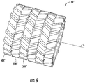
- a mid-segment 48" may generally include the herringbone pattern of the second embodiment, but with the circumferential off-set of the first embodiment.
- the Herringbone pattern combined with the circumferential off-set between fins may promote further cooling air turbulence to further enhance heat transfer capability.
- the enhancement of heat transfer capability i.e., breaking the thermal boundary layer
- a mid-segment 48'" may include a plurality of fins 54"'.
- Each fin 54'" may be a projecting pin or stanchion (e.g., cylindrical in shape).
- a mid-segment 48"" may include a plurality of fins 54"". Each fin 54"" may be in the shape of an air-foil.
- Advantages and benefits of the present disclosure include improved heat transfer capability at the thermal boundary layer of each cooling fin. With the resulting higher heat transfer coefficient, cooling performance is optimized and can be varied by assembling patterns. Additional benefits include ease of manufacturing, and the ability to operate the electric motor at higher current density and/or higher power density.
Landscapes
- Engineering & Computer Science (AREA)
- Power Engineering (AREA)
- Physics & Mathematics (AREA)
- Thermal Sciences (AREA)
- Motor Or Generator Cooling System (AREA)
Abstract
Description
- The present disclosure relates to an electric motor, and more particularly, to a stator assembly that can cool an electric motor.
- Traditional electric motors may include a stator, a rotor, and an aluminum frame with cooling fins located at an exterior of the frame. The cooling fins are adapted to dissipate heat generated in the electric motor due to electromagnetic losses both in the copper windings and laminated steel core (i.e., hysteresis and eddy current). The cooling fins may dissipate the heat via natural and/or forced convection depending upon the design of the motor. Traditional manufacturing techniques include machining of an aluminum structure into straight fins and then integrating (e.g., shrink fit) the structure with the stator at the outer diameter surface. Improvements in manufacturing techniques, versatility in fin design, and optimizing cooling capability are desirable.
- A stator assembly of an electric motor according to one, non-limiting, embodiment of the present disclosure includes a plurality of ring structures centered to an axis, each of the plurality of ring structures including a ring and a plurality of cooling fins projecting radially from and spaced circumferentially about the ring, wherein each of the plurality of ring structures is disposed axially adjacent to another one of the plurality of ring structures.
- Additionally to the foregoing embodiment, the stator assembly includes electrical windings disposed radially inward from the plurality of ring structures.
- In the alternative or additionally thereto, in the foregoing embodiment, each one of the plurality of cooling fins lies within an imaginary plane containing the axis.
- In the alternative or additionally thereto, in the foregoing embodiment, the plurality of cooling fins of a first ring structure of the plurality of cooling fins are circumferentially offset from the plurality of cooling fins of an adjacent ring structure of the plurality of ring structures.
- In the alternative or additionally thereto, in the foregoing embodiment, the plurality of cooling fins are helical.
- In the alternative or additionally thereto, in the foregoing embodiment, the plurality of cooling fins include a first plurality of helical cooling fins angled in a first direction and a second plurality of helical cooling fins angled in an opposite direction.
- In the alternative or additionally thereto, in the foregoing embodiment, the first plurality of helical cooling fins is axially adjacent to and circumferentially offset from the second plurality of helical cooling fins.
- In the alternative or additionally thereto, in the foregoing embodiment, the first plurality of helical cooling fins is axially adjacent to and circumferentially aligned to the second plurality of helical cooling fins.
- An electric motor according to another, non-limiting, embodiment includes a rotor adapted for rotation about an axis; and a stator assembly surrounding the rotor. The stator assembly includes windings; a first ring structure disposed radially outward from and concentric to the rotor, the first ring structure including a first ring and a first plurality of cooling fins spaced circumferentially about and projecting radially from the first ring; and a second ring structure disposed radially outward from and concentric to the rotor, the second ring structure including a second ring and a second plurality of cooling fins spaced circumferentially about and projecting radially from the second ring, wherein the first ring structure is axially adjacent to the second ring structure.
- Additionally to the foregoing embodiment, the electric motor includes a fan adapted to rotate with the rotor and configured to induce airflow over the first and second plurality of cooling fins.
- In the alternative or additionally thereto, in the foregoing embodiment, the first and second ring structures are part of a stator assembly.
- In the alternative or additionally thereto, in the foregoing embodiment, the electric motor includes an external housing, wherein the first and second ring structures are an integral part of the housing.
- In the alternative or additionally thereto, in the foregoing embodiment, each one of the first plurality of cooling fins include a first forward edge and an opposite first rearward edge, and each one of the second plurality of cooling fins include a second forward edge and an opposite second rearward edge, and wherein the first forward edge is circumferentially aligned to the first rearward edge and the second forward edge is circumferentially aligned to the second rearward edge.
- In the alternative or additionally thereto, in the foregoing embodiment, the first forward edge is circumferentially aligned and axially adjacent to the second rearward edge.
- In the alternative or additionally thereto, in the foregoing embodiment, the first forward edge is axially adjacent to and circumferentially offset from the second rearward edge.
- In the alternative or additionally thereto, in the foregoing embodiment, the first and second plurality of cooling fins are helical.
- In the alternative or additionally thereto, in the foregoing embodiment, each one of the first plurality of cooling fins include a first forward edge and an opposite first rearward edge, and each one of the second plurality of cooling fins include a second forward edge and an opposite second rearward edge, and wherein the first forward edge is circumferentially offset from the first rearward edge and the second forward edge is circumferentially offset from the second rearward edge.
- In the alternative or additionally thereto, in the foregoing embodiment, each one of at least one of the first and second plurality of cooling fins is pin-shaped.
- In the alternative or additionally thereto, in the foregoing embodiment, each one of at least one of the first and second plurality of cooling fins is shaped like an air-foil.
- In the alternative or additionally thereto, in the foregoing embodiment, the stator assembly includes an index feature carried between the first and second rings for circumferentially aligning the first ring to the second ring
- The foregoing features and elements may be combined in various combinations without exclusivity, unless expressly indicated otherwise. These features and elements as well as the operation thereof will become more apparent in light of the following description and the accompanying drawings. However, it should be understood that the following description and drawings are intended to be exemplary in nature and non-limiting.
- Various features will become apparent to those skilled in the art from the following detailed description of the disclosed non-limiting embodiments. The drawings that accompany the detailed description can be briefly described as follows:
-
FIG. 1 is a perspective view of an electric motor with portions removed to show internal detail, and as one exemplary embodiment; -
FIG. 2 is a perspective view of a stator assembly of the electric motor; -
FIG. 3 is a perspective view of a ring structure of the stator assembly; -
FIG. 4 is a perspective view of a second embodiment of the ring structure; -
FIG. 5 is a perspective view of a second embodiment of the stator assembly; -
FIG. 6 is a perspective view of a third embodiment of the stator assembly; -
FIG. 7 is a perspective view of a fourth embodiment of the stator assembly; and -
FIG. 8 is a perspective view of a fifth embodiment of the stator assembly. - Referring to
FIG. 1 , anelectric motor 20 is illustrated as one, non-limiting, embodiment of the present disclosure. The illustratedelectric motor 20 includes arotor 22 adapted to rotate about a rotation axis A, astator assembly 24, a rotatingshaft 26,bearings 28, acooling fan 30, afan cage 32, aterminal box 34, and other components. Theshaft 26 is centered to the axis A and may be fixed to therotor 22, such that therotor 22 and theshaft 26 rotate together as one piece. Thestator assembly 24 is generally located radially outward from therotor 22 andshaft 26, and is generally stationary during operation of theelectric motor 20. - The
bearings 28 are adapted to provide structural support and minimize friction between the rotatingshaft 26 and thestationary stator assembly 24. In one embodiment, thebearings 28 may be located axially between, and supported by, respective, opposite,end portions shaft 26 and thestator assembly 24. Theend portions rotor 22.End portion 36 may be attached to thecooling fan 30 for rotation of the fan, andend portion 38 may be engaged to any variety of external devices (not shown) adapted to be driven by theelectric motor 20. - The
stator assembly 24 may includestator windings 40, and an external housing orcasing 42. Theelectrical windings 40 are generally located radially inward from thecasing 42, and may be generally supported by and fixed to, thecasing 42. Thecasing 42 may includeopposite end segments end segments end segment shaft 26 and the mid-segment 48, and may support a respective bearing 28. In one embodiment, theterminal box 34 may be attached to an external surface of themid-segment 48 for facilitating an electrical connection between thestator windings 40 and an external power source (not shown). - The
fan cage 32 facilitates protection of thefan 30, and may provide a safety function by preventing contact of the rotating fan with a person. Thecooling fan 30 may generally be axially located between theend segment 44 of theexternal casing 42 and thefan cage 32. In one embodiment, thefan cage 32 is attached to theend segment 44 of thecasing 42. - Referring to
FIGS. 2 and3 , the mid-segment 48 of theexternal casing 42 may include a plurality ofring structures 50 axially aligned side-by-side. Eachring structure 50 may include abase ring 52 and a plurality ofcooling fins 54. Thecooling fins 54 may project radially outward from thering 52, and may be circumferentially distributed about the ring. Eachfin 54 may include an axiallyforward edge 56 and arearward edge 58. Theedges ring 52. Eachfin 54 may further include opposite facingsurfaces edges arrow 64 inFIG. 2 ) of theshaft 26,surface 60 may be a leading surface, andsurface 62 may be a trailing surface. In one example, eachfin 54 may generally lie within a respective, imaginary, plane that contains the axis A. That is,fin 54 may span axially and radially, but may not be angled, or may not be twisted, in a circumferential direction. - Each
base ring 52 may include anindex feature 65 configured to circumferentially align thebase ring 52 to the next, axially adjacent base ring. As illustrated theindex feature 65 may include anaxially projecting tab 65A adapted to project into arecess 65B of theindex feature 65 and in the adjacent base ring. During operation of theelectric motor 20, theindex feature 65 may also prevent circumferential misalignment of the adjacent base rings 52, and thus misalignment of the respective, axially adjacent,fins 54. - In one embodiment, the
fins 54 of afirst ring structure 50 may be circumferentially offset from thefins 54 of the next adjacent ring structure. More specifically, the plurality ofring structures 50 may include a multitude of axially alternatingring structures Ring structure 50A may be axially adjacent to and disposed between tworing structures 50B, and so on. When thestator assembly 24 is fully assembled, thefins 54 ofring structure 50A may be circumferentially aligned with one-another, and thefins 54 of thering structure 50B may be circumferentially aligned with one-another. However, thefins 54 ofring structure 50A may be circumferentially centered betweenadjacent fins 54 of the axiallyadjacent ring structure 50B. This pattern may generally repeat itself throughout the plurality ofring structures 50. - The
ring structures stator assembly 24. The number ofring structures 50 used in any one application of amotor 20 may be dependent upon the motor itself and/or application and environment of use. It is contemplated and understood that one ring structure type may be applied to a variety of electric motors thereby optimizing motor design versatility and reducing manufacturing and part distribution costs. - During operation of the
electric motor 20, thefan 30 produces a flow of cooling air (seearrow 66 inFIG. 2 ) through thering structures 50 of thestator assembly 24. In the example of the circumferentially offsetring structures 50, the flow of air may first impinge upon the rearward edges 58 of the offsetfins 54 of thefirst ring structure 50A before flowing past the associated fin surfaces 60, 62, then impinging the rearward edges 58 of thefins 54 of thenext ring structure 50B, and so on. The impingement of cooling air against the exposed edges 58 causes an air flow turbulence that increases heat transfer, thereby improving the cooling capability of the fins. - Referring to
FIGS. 4 and5 , a second embodiment of the ring structure is illustrated wherein like elements to the first embodiment have like identifying numerals except with the addition of a prime symbol suffix. The ring structure 50' may include a plurality of fins 54' each having an axially forward edge 56' and a rearward edge 58'. The edges 56', 58' may substantially project radially outward from the ring 52'. Each fin 54' may further include opposite facingsurfaces 60', 62' each substantially spanning, both axially and circumferentially (i.e., fin pitch or slant), between the edges 56', 58'. In one embodiment, thefins 54, of afirst ring structure 50A' may be pitched at an opposite angle than the fins 54' of an axially adjacentsecond ring structure 50B' of the plurality of ring structures 50'. - Referring to
FIG. 5 , when a mid-segment 48' of a stator assembly is fully assembled, the forward edges 56' of the fins 54' of thering structure 50A' may be circumferentially aligned to, and may be directly axially opposed to, the rearward edges 58' of the axiallyadjacent ring structure 50B'. Similarly, the forward edges 56' of the fins 54' of thering structure 50B' may be circumferentially aligned to, and may be directly axially opposed to, the rearward edges 58' of thenext ring structure 50A'. When fully assembled, the mid-segment 48' may resemble a pattern that is herringbone-like. The individual ring structures 50' may be helical ring structures (i.e., helical-like, or chevron fins). The herringbone pattern of the mid-segment 48' causes cooling air flow turbulence that promotes heat transfer. - Referring to
FIG. 6 , a third embodiment of a mid-segment of a stator assembly is illustrated wherein like elements to the first and/or second embodiment have like identifying numerals except with the addition of a double prime symbol suffix. A mid-segment 48" may generally include the herringbone pattern of the second embodiment, but with the circumferential off-set of the first embodiment. The Herringbone pattern combined with the circumferential off-set between fins may promote further cooling air turbulence to further enhance heat transfer capability. However, the enhancement of heat transfer capability (i.e., breaking the thermal boundary layer) may be predicated on the allowable increase in load placed, for example, on the cooling fan. - Referring to
FIG. 7 , a fourth embodiment of a mid-segment of a stator assembly is illustrated wherein like elements to the first embodiment have like identifying numerals except with the addition of a triple prime symbol suffix. A mid-segment 48'" may include a plurality offins 54"'. Each fin 54'" may be a projecting pin or stanchion (e.g., cylindrical in shape). - Referring to
FIG. 8 , a fifth embodiment of a mid-segment of a stator assembly is illustrated wherein like elements to the first embodiment have like identifying numerals except with the addition of a quad prime symbol suffix. A mid-segment 48"" may include a plurality offins 54"". Eachfin 54"" may be in the shape of an air-foil. - Advantages and benefits of the present disclosure include improved heat transfer capability at the thermal boundary layer of each cooling fin. With the resulting higher heat transfer coefficient, cooling performance is optimized and can be varied by assembling patterns. Additional benefits include ease of manufacturing, and the ability to operate the electric motor at higher current density and/or higher power density.
- The term "about" is intended to include the degree of error associated with measurement of the particular quantity based upon the equipment available at the time of filing the application. For example, "about" can include a range of ± 8% or 5%, or 2% of a given value.
- The terminology used herein is for the purpose of describing particular embodiments only and is not intended to be limiting of the present disclosure. As used herein, the singular forms "a", "an" and "the" are intended to include the plural forms as well, unless the context clearly indicates otherwise. It will be further understood that the terms "comprises" and/or "comprising," when used in this specification, specify the presence of stated features, integers, steps, operations, elements, and/or components, but do not preclude the presence or addition of one or more other features, integers, steps, operations, element components, and/or groups thereof.
- While the present disclosure has been described with reference to an exemplary embodiment or embodiments, it will be understood by those skilled in the art that various changes may be made and equivalents may be substituted for elements thereof without departing from the scope of the present disclosure. In addition, many modifications may be made to adapt a particular situation or material to the teachings of the present disclosure without departing from the essential scope thereof. Therefore, it is intended that the present disclosure not be limited to the particular embodiment disclosed as the best mode contemplated for carrying out this present disclosure, but that the present disclosure will include all embodiments falling within the scope of the claims.
Claims (15)
- A stator assembly (24) of an electric motor (20) comprising:
a plurality of ring structures (50A,50B) centered to an axis, each of the plurality of ring structures (50A,50B) including a ring and a plurality of cooling fins (54) projecting radially from and spaced circumferentially about the ring, wherein each of the plurality of ring structures is disposed axially adjacent to another one of the plurality of ring structures (50A,50B). - The stator assembly set forth in claim 1, further comprising:
electrical windings disposed radially inward from the plurality of ring structures (50A,50B). - The stator assembly set forth in claim 1, wherein each one of the plurality of cooling fins lies within an imaginary plane containing the axis.
- The stator assembly set forth in claim 3, wherein the plurality of cooling fins of a first ring structure (50A,50B) of the plurality of cooling fins (54) are circumferentially offset from the plurality of cooling fins (54) of an adjacent ring structure (50A,50B) of the plurality of ring structures (50A,50B).
- The stator assembly set forth in any preceding claim, wherein the plurality of cooling fins (54) are helical.
- The stator assembly set forth in claim 5, wherein the plurality of cooling fins include a first plurality of helical cooling fins angled in a first direction and a second plurality of helical cooling fins angled in an opposite direction.
- The stator assembly set forth in claim 6, wherein the first plurality of helical cooling fins (54) is axially adjacent to and circumferentially offset from the second plurality of helical cooling fins (54).
- The stator assembly set forth in claim 6, wherein the first plurality of helical cooling fins (54) is axially adjacent to and circumferentially aligned to the second plurality of helical cooling fins (54).
- An electric motor (20) comprising:a rotor (22) adapted for rotation about an axis; anda stator assembly (24) surrounding the rotor, the stator assembly including:windings;a first ring structure (50A,50B) disposed radially outward from and concentric to the rotor (22), the first ring structure (50A,50B) including a first ring and a first plurality of cooling fins (54) spaced circumferentially about and projecting radially from the first ring; anda second ring structure (50A,50B) disposed radially outward from and concentric to the rotor (22), the second ring structure (50A,50B) including a second ring and a second plurality of cooling fins (54) spaced circumferentially about and projecting radially from the second ring, wherein the first ring structure (50A,50B) is axially adjacent to the second ring structure (50A,50B).
- The electric motor set forth in claim 9, further comprising:
a fan adapted to rotate with the rotor (22) and configured to induce airflow over the first and second plurality of cooling fins (54). - The electric motor set forth in claim 9 or 10, wherein the first and second ring structures are part of a stator assembly (24).
- The electric motor set forth in claim 9, 10 or 11, further comprising:
an external housing, wherein the first and second ring structures (50A,50B) are an integral part of the housing. - The electric motor set forth in any of claims 9 to 12, wherein each one of the first plurality of cooling fins (54) include a first forward edge (56') and an opposite first rearward edge (58'), and each one of the second plurality of cooling fins (54) include a second forward edge (56') and an opposite second rearward edge (58'), and wherein the first forward edge (56') is circumferentially aligned to the first rearward edge (58') and the second forward edge (56') is circumferentially aligned to the second rearward edge (58').
- The electric motor set forth in claim 13, wherein the first forward edge (56') is circumferentially aligned and axially adjacent to the second rearward edge.
- The electric motor set forth in claim 13, wherein the first forward edge (56') is axially adjacent to and circumferentially offset from the second rearward edge (58').
Applications Claiming Priority (1)
| Application Number | Priority Date | Filing Date | Title |
|---|---|---|---|
| US15/817,738 US20190157922A1 (en) | 2017-11-20 | 2017-11-20 | Electric motor |
Publications (2)
| Publication Number | Publication Date |
|---|---|
| EP3487042A1 true EP3487042A1 (en) | 2019-05-22 |
| EP3487042B1 EP3487042B1 (en) | 2021-08-11 |
Family
ID=64316427
Family Applications (1)
| Application Number | Title | Priority Date | Filing Date |
|---|---|---|---|
| EP18206290.1A Active EP3487042B1 (en) | 2017-11-20 | 2018-11-14 | Electric motor |
Country Status (2)
| Country | Link |
|---|---|
| US (1) | US20190157922A1 (en) |
| EP (1) | EP3487042B1 (en) |
Cited By (4)
| Publication number | Priority date | Publication date | Assignee | Title |
|---|---|---|---|---|
| CN110912366A (en) * | 2019-12-11 | 2020-03-24 | 杭州美时美刻物联网科技有限公司 | Permanent magnet servo motor |
| WO2023285810A1 (en) * | 2021-07-13 | 2023-01-19 | Dyson Technology Limited | A brushless motor |
| WO2023285811A1 (en) * | 2021-07-13 | 2023-01-19 | Dyson Technology Limited | A brushless motor |
| GB2610691B (en) * | 2021-07-13 | 2024-09-04 | Dyson Technology Ltd | A brushless motor |
Families Citing this family (8)
| Publication number | Priority date | Publication date | Assignee | Title |
|---|---|---|---|---|
| KR102183465B1 (en) * | 2019-07-12 | 2020-11-26 | 현대일렉트릭앤에너지시스템(주) | Cooling apparatus of rotating machine |
| KR102707658B1 (en) * | 2021-06-09 | 2024-09-19 | 우시 인피모션 테크놀로지 컴퍼니 리미티드 | Stator cores, motors, powertrains, automobiles and vehicles |
| CN114285197A (en) * | 2021-12-30 | 2022-04-05 | 浙江吉利控股集团有限公司 | Stator core, motor, power assembly and car |
| CN113691051B (en) * | 2021-08-18 | 2022-09-27 | 珠海格力电器股份有限公司 | Motor casing and motor |
| JP7768711B2 (en) * | 2021-09-29 | 2025-11-12 | ニデック株式会社 | Electric power unit |
| US12424908B2 (en) * | 2022-05-26 | 2025-09-23 | Schaeffler Technologies AG & Co. KG | Electric drive unit having a heat exchanger |
| KR102753912B1 (en) * | 2022-11-30 | 2025-01-14 | 한국전기연구원 | Stator core, and motor having the same |
| US20250062655A1 (en) * | 2023-08-17 | 2025-02-20 | Schaeffler Technologies AG & Co. KG | Electric drive unit that includes a fluid flow path |
Citations (6)
| Publication number | Priority date | Publication date | Assignee | Title |
|---|---|---|---|---|
| US5982071A (en) * | 1998-08-13 | 1999-11-09 | Able Corporation | Cooling of electrical machinery |
| JP2002013467A (en) * | 2000-04-28 | 2002-01-18 | Mitsubishi Electric Corp | Wind power generator |
| EP2058926A2 (en) * | 2007-11-09 | 2009-05-13 | Hamilton Sundstrand Corporation | Enhanced motor cooling system |
| JP2013153555A (en) * | 2012-01-24 | 2013-08-08 | Mitsubishi Electric Corp | Motor |
| EP3076526A1 (en) * | 2015-04-02 | 2016-10-05 | Hamilton Sundstrand Corporation | Stator heat transfer feature |
| WO2017161527A1 (en) * | 2016-03-24 | 2017-09-28 | Robert Bosch Gmbh | Stator lamination and electrical machine |
Family Cites Families (6)
| Publication number | Priority date | Publication date | Assignee | Title |
|---|---|---|---|---|
| US2761984A (en) * | 1952-01-21 | 1956-09-04 | Kleinschanzlin Pumpen Ag | Core and shell for electromotors |
| US5382859A (en) * | 1992-09-01 | 1995-01-17 | Unique Mobility | Stator and method of constructing same for high power density electric motors and generators |
| JPH10215541A (en) * | 1997-01-29 | 1998-08-11 | Aichi Electric Co Ltd | Electric motor with cooling fins for heat dissipation |
| US7633194B2 (en) * | 2006-10-26 | 2009-12-15 | Gm Global Technology Operations, Inc. | Apparatus for cooling stator lamination stacks of electrical machines |
| JP5459110B2 (en) * | 2010-06-30 | 2014-04-02 | 株式会社デンソー | Rotating electric machine stator |
| US9306432B2 (en) * | 2012-10-31 | 2016-04-05 | Hamilton Sundstrand Corporation | Stator cooling channel tolerant to localized blockage |
-
2017
- 2017-11-20 US US15/817,738 patent/US20190157922A1/en not_active Abandoned
-
2018
- 2018-11-14 EP EP18206290.1A patent/EP3487042B1/en active Active
Patent Citations (6)
| Publication number | Priority date | Publication date | Assignee | Title |
|---|---|---|---|---|
| US5982071A (en) * | 1998-08-13 | 1999-11-09 | Able Corporation | Cooling of electrical machinery |
| JP2002013467A (en) * | 2000-04-28 | 2002-01-18 | Mitsubishi Electric Corp | Wind power generator |
| EP2058926A2 (en) * | 2007-11-09 | 2009-05-13 | Hamilton Sundstrand Corporation | Enhanced motor cooling system |
| JP2013153555A (en) * | 2012-01-24 | 2013-08-08 | Mitsubishi Electric Corp | Motor |
| EP3076526A1 (en) * | 2015-04-02 | 2016-10-05 | Hamilton Sundstrand Corporation | Stator heat transfer feature |
| WO2017161527A1 (en) * | 2016-03-24 | 2017-09-28 | Robert Bosch Gmbh | Stator lamination and electrical machine |
Cited By (4)
| Publication number | Priority date | Publication date | Assignee | Title |
|---|---|---|---|---|
| CN110912366A (en) * | 2019-12-11 | 2020-03-24 | 杭州美时美刻物联网科技有限公司 | Permanent magnet servo motor |
| WO2023285810A1 (en) * | 2021-07-13 | 2023-01-19 | Dyson Technology Limited | A brushless motor |
| WO2023285811A1 (en) * | 2021-07-13 | 2023-01-19 | Dyson Technology Limited | A brushless motor |
| GB2610691B (en) * | 2021-07-13 | 2024-09-04 | Dyson Technology Ltd | A brushless motor |
Also Published As
| Publication number | Publication date |
|---|---|
| EP3487042B1 (en) | 2021-08-11 |
| US20190157922A1 (en) | 2019-05-23 |
Similar Documents
| Publication | Publication Date | Title |
|---|---|---|
| EP3487042B1 (en) | Electric motor | |
| US20220393527A1 (en) | Axial flux motor with air cooling system | |
| US5982071A (en) | Cooling of electrical machinery | |
| US6573631B2 (en) | Automotive alternator | |
| US9413208B2 (en) | Enhanced cooling of enclosed air cooled high power motors | |
| US8294309B2 (en) | Electrical rotating machine | |
| US5986366A (en) | Rotor for a dynamoelectric machine | |
| CN105264752A (en) | Electric machine with liquid cooled housing | |
| US7358630B2 (en) | Ventilating device for rotary electrical machine | |
| CA2961893C (en) | External fan and drive end housing for an air cooled alternator | |
| DE102022134926A1 (en) | ELECTRICAL MACHINE WITH AN AIR COOLING SYSTEM | |
| KR20070026069A (en) | Automotive alternator with rectifier with high strength heat sink | |
| CN101902095A (en) | Voltage Regulators for Automotive Alternators | |
| US6121710A (en) | Stator structure for industrial cooling fans | |
| US20250158488A1 (en) | Enhanced convective rotor cooling | |
| US20170179792A1 (en) | Enclosed motor utilizing recirculating coolant air | |
| CN113853728A (en) | motor | |
| CN206585445U (en) | Squirrel cage motor | |
| CN212660020U (en) | Winding type motor rotor with radiating winding end part | |
| CN222868629U (en) | Motor | |
| CN220307037U (en) | A heat dissipation mechanism for a cast aluminum rotor oil-cooled motor and an oil-cooled motor | |
| JPH07170693A (en) | Rotating machine rotor | |
| EP3553920A1 (en) | Cooling device for a stator of an electrical generator | |
| EP2899850B1 (en) | Electric generator for a wind turbine with stator gaps varying in axial direction of the generator | |
| CN217282579U (en) | Motors, motor units and electronic equipment |
Legal Events
| Date | Code | Title | Description |
|---|---|---|---|
| PUAI | Public reference made under article 153(3) epc to a published international application that has entered the european phase |
Free format text: ORIGINAL CODE: 0009012 |
|
| STAA | Information on the status of an ep patent application or granted ep patent |
Free format text: STATUS: THE APPLICATION HAS BEEN PUBLISHED |
|
| AK | Designated contracting states |
Kind code of ref document: A1 Designated state(s): AL AT BE BG CH CY CZ DE DK EE ES FI FR GB GR HR HU IE IS IT LI LT LU LV MC MK MT NL NO PL PT RO RS SE SI SK SM TR |
|
| AX | Request for extension of the european patent |
Extension state: BA ME |
|
| STAA | Information on the status of an ep patent application or granted ep patent |
Free format text: STATUS: REQUEST FOR EXAMINATION WAS MADE |
|
| 17P | Request for examination filed |
Effective date: 20191118 |
|
| RBV | Designated contracting states (corrected) |
Designated state(s): AL AT BE BG CH CY CZ DE DK EE ES FI FR GB GR HR HU IE IS IT LI LT LU LV MC MK MT NL NO PL PT RO RS SE SI SK SM TR |
|
| STAA | Information on the status of an ep patent application or granted ep patent |
Free format text: STATUS: EXAMINATION IS IN PROGRESS |
|
| 17Q | First examination report despatched |
Effective date: 20200714 |
|
| GRAP | Despatch of communication of intention to grant a patent |
Free format text: ORIGINAL CODE: EPIDOSNIGR1 |
|
| STAA | Information on the status of an ep patent application or granted ep patent |
Free format text: STATUS: GRANT OF PATENT IS INTENDED |
|
| INTG | Intention to grant announced |
Effective date: 20210315 |
|
| RIN1 | Information on inventor provided before grant (corrected) |
Inventor name: YUN, THOMAS M. Inventor name: TANGUDU, JAGADEESH |
|
| GRAS | Grant fee paid |
Free format text: ORIGINAL CODE: EPIDOSNIGR3 |
|
| GRAA | (expected) grant |
Free format text: ORIGINAL CODE: 0009210 |
|
| STAA | Information on the status of an ep patent application or granted ep patent |
Free format text: STATUS: THE PATENT HAS BEEN GRANTED |
|
| AK | Designated contracting states |
Kind code of ref document: B1 Designated state(s): AL AT BE BG CH CY CZ DE DK EE ES FI FR GB GR HR HU IE IS IT LI LT LU LV MC MK MT NL NO PL PT RO RS SE SI SK SM TR |
|
| REG | Reference to a national code |
Ref country code: CH Ref legal event code: EP |
|
| REG | Reference to a national code |
Ref country code: DE Ref legal event code: R096 Ref document number: 602018021550 Country of ref document: DE |
|
| REG | Reference to a national code |
Ref country code: IE Ref legal event code: FG4D Ref country code: AT Ref legal event code: REF Ref document number: 1420396 Country of ref document: AT Kind code of ref document: T Effective date: 20210915 |
|
| REG | Reference to a national code |
Ref country code: LT Ref legal event code: MG9D |
|
| REG | Reference to a national code |
Ref country code: NL Ref legal event code: MP Effective date: 20210811 |
|
| REG | Reference to a national code |
Ref country code: AT Ref legal event code: MK05 Ref document number: 1420396 Country of ref document: AT Kind code of ref document: T Effective date: 20210811 |
|
| PG25 | Lapsed in a contracting state [announced via postgrant information from national office to epo] |
Ref country code: PT Free format text: LAPSE BECAUSE OF FAILURE TO SUBMIT A TRANSLATION OF THE DESCRIPTION OR TO PAY THE FEE WITHIN THE PRESCRIBED TIME-LIMIT Effective date: 20211213 Ref country code: NO Free format text: LAPSE BECAUSE OF FAILURE TO SUBMIT A TRANSLATION OF THE DESCRIPTION OR TO PAY THE FEE WITHIN THE PRESCRIBED TIME-LIMIT Effective date: 20211111 Ref country code: AT Free format text: LAPSE BECAUSE OF FAILURE TO SUBMIT A TRANSLATION OF THE DESCRIPTION OR TO PAY THE FEE WITHIN THE PRESCRIBED TIME-LIMIT Effective date: 20210811 Ref country code: BG Free format text: LAPSE BECAUSE OF FAILURE TO SUBMIT A TRANSLATION OF THE DESCRIPTION OR TO PAY THE FEE WITHIN THE PRESCRIBED TIME-LIMIT Effective date: 20211111 Ref country code: LT Free format text: LAPSE BECAUSE OF FAILURE TO SUBMIT A TRANSLATION OF THE DESCRIPTION OR TO PAY THE FEE WITHIN THE PRESCRIBED TIME-LIMIT Effective date: 20210811 Ref country code: SE Free format text: LAPSE BECAUSE OF FAILURE TO SUBMIT A TRANSLATION OF THE DESCRIPTION OR TO PAY THE FEE WITHIN THE PRESCRIBED TIME-LIMIT Effective date: 20210811 Ref country code: RS Free format text: LAPSE BECAUSE OF FAILURE TO SUBMIT A TRANSLATION OF THE DESCRIPTION OR TO PAY THE FEE WITHIN THE PRESCRIBED TIME-LIMIT Effective date: 20210811 Ref country code: FI Free format text: LAPSE BECAUSE OF FAILURE TO SUBMIT A TRANSLATION OF THE DESCRIPTION OR TO PAY THE FEE WITHIN THE PRESCRIBED TIME-LIMIT Effective date: 20210811 Ref country code: ES Free format text: LAPSE BECAUSE OF FAILURE TO SUBMIT A TRANSLATION OF THE DESCRIPTION OR TO PAY THE FEE WITHIN THE PRESCRIBED TIME-LIMIT Effective date: 20210811 Ref country code: HR Free format text: LAPSE BECAUSE OF FAILURE TO SUBMIT A TRANSLATION OF THE DESCRIPTION OR TO PAY THE FEE WITHIN THE PRESCRIBED TIME-LIMIT Effective date: 20210811 |
|
| PG25 | Lapsed in a contracting state [announced via postgrant information from national office to epo] |
Ref country code: PL Free format text: LAPSE BECAUSE OF FAILURE TO SUBMIT A TRANSLATION OF THE DESCRIPTION OR TO PAY THE FEE WITHIN THE PRESCRIBED TIME-LIMIT Effective date: 20210811 Ref country code: LV Free format text: LAPSE BECAUSE OF FAILURE TO SUBMIT A TRANSLATION OF THE DESCRIPTION OR TO PAY THE FEE WITHIN THE PRESCRIBED TIME-LIMIT Effective date: 20210811 Ref country code: GR Free format text: LAPSE BECAUSE OF FAILURE TO SUBMIT A TRANSLATION OF THE DESCRIPTION OR TO PAY THE FEE WITHIN THE PRESCRIBED TIME-LIMIT Effective date: 20211112 |
|
| PG25 | Lapsed in a contracting state [announced via postgrant information from national office to epo] |
Ref country code: NL Free format text: LAPSE BECAUSE OF FAILURE TO SUBMIT A TRANSLATION OF THE DESCRIPTION OR TO PAY THE FEE WITHIN THE PRESCRIBED TIME-LIMIT Effective date: 20210811 |
|
| PG25 | Lapsed in a contracting state [announced via postgrant information from national office to epo] |
Ref country code: DK Free format text: LAPSE BECAUSE OF FAILURE TO SUBMIT A TRANSLATION OF THE DESCRIPTION OR TO PAY THE FEE WITHIN THE PRESCRIBED TIME-LIMIT Effective date: 20210811 |
|
| REG | Reference to a national code |
Ref country code: DE Ref legal event code: R097 Ref document number: 602018021550 Country of ref document: DE |
|
| PG25 | Lapsed in a contracting state [announced via postgrant information from national office to epo] |
Ref country code: SM Free format text: LAPSE BECAUSE OF FAILURE TO SUBMIT A TRANSLATION OF THE DESCRIPTION OR TO PAY THE FEE WITHIN THE PRESCRIBED TIME-LIMIT Effective date: 20210811 Ref country code: SK Free format text: LAPSE BECAUSE OF FAILURE TO SUBMIT A TRANSLATION OF THE DESCRIPTION OR TO PAY THE FEE WITHIN THE PRESCRIBED TIME-LIMIT Effective date: 20210811 Ref country code: RO Free format text: LAPSE BECAUSE OF FAILURE TO SUBMIT A TRANSLATION OF THE DESCRIPTION OR TO PAY THE FEE WITHIN THE PRESCRIBED TIME-LIMIT Effective date: 20210811 Ref country code: EE Free format text: LAPSE BECAUSE OF FAILURE TO SUBMIT A TRANSLATION OF THE DESCRIPTION OR TO PAY THE FEE WITHIN THE PRESCRIBED TIME-LIMIT Effective date: 20210811 Ref country code: CZ Free format text: LAPSE BECAUSE OF FAILURE TO SUBMIT A TRANSLATION OF THE DESCRIPTION OR TO PAY THE FEE WITHIN THE PRESCRIBED TIME-LIMIT Effective date: 20210811 Ref country code: AL Free format text: LAPSE BECAUSE OF FAILURE TO SUBMIT A TRANSLATION OF THE DESCRIPTION OR TO PAY THE FEE WITHIN THE PRESCRIBED TIME-LIMIT Effective date: 20210811 |
|
| PLBE | No opposition filed within time limit |
Free format text: ORIGINAL CODE: 0009261 |
|
| STAA | Information on the status of an ep patent application or granted ep patent |
Free format text: STATUS: NO OPPOSITION FILED WITHIN TIME LIMIT |
|
| PG25 | Lapsed in a contracting state [announced via postgrant information from national office to epo] |
Ref country code: MC Free format text: LAPSE BECAUSE OF FAILURE TO SUBMIT A TRANSLATION OF THE DESCRIPTION OR TO PAY THE FEE WITHIN THE PRESCRIBED TIME-LIMIT Effective date: 20210811 |
|
| REG | Reference to a national code |
Ref country code: CH Ref legal event code: PL |
|
| 26N | No opposition filed |
Effective date: 20220512 |
|
| PG25 | Lapsed in a contracting state [announced via postgrant information from national office to epo] |
Ref country code: LU Free format text: LAPSE BECAUSE OF NON-PAYMENT OF DUE FEES Effective date: 20211114 Ref country code: IT Free format text: LAPSE BECAUSE OF FAILURE TO SUBMIT A TRANSLATION OF THE DESCRIPTION OR TO PAY THE FEE WITHIN THE PRESCRIBED TIME-LIMIT Effective date: 20210811 Ref country code: BE Free format text: LAPSE BECAUSE OF NON-PAYMENT OF DUE FEES Effective date: 20211130 |
|
| REG | Reference to a national code |
Ref country code: BE Ref legal event code: MM Effective date: 20211130 |
|
| PG25 | Lapsed in a contracting state [announced via postgrant information from national office to epo] |
Ref country code: SI Free format text: LAPSE BECAUSE OF FAILURE TO SUBMIT A TRANSLATION OF THE DESCRIPTION OR TO PAY THE FEE WITHIN THE PRESCRIBED TIME-LIMIT Effective date: 20210811 Ref country code: LI Free format text: LAPSE BECAUSE OF NON-PAYMENT OF DUE FEES Effective date: 20211130 Ref country code: CH Free format text: LAPSE BECAUSE OF NON-PAYMENT OF DUE FEES Effective date: 20211130 |
|
| PG25 | Lapsed in a contracting state [announced via postgrant information from national office to epo] |
Ref country code: IE Free format text: LAPSE BECAUSE OF NON-PAYMENT OF DUE FEES Effective date: 20211114 |
|
| P01 | Opt-out of the competence of the unified patent court (upc) registered |
Effective date: 20230522 |
|
| PG25 | Lapsed in a contracting state [announced via postgrant information from national office to epo] |
Ref country code: CY Free format text: LAPSE BECAUSE OF FAILURE TO SUBMIT A TRANSLATION OF THE DESCRIPTION OR TO PAY THE FEE WITHIN THE PRESCRIBED TIME-LIMIT Effective date: 20210811 |
|
| PG25 | Lapsed in a contracting state [announced via postgrant information from national office to epo] |
Ref country code: HU Free format text: LAPSE BECAUSE OF FAILURE TO SUBMIT A TRANSLATION OF THE DESCRIPTION OR TO PAY THE FEE WITHIN THE PRESCRIBED TIME-LIMIT; INVALID AB INITIO Effective date: 20181114 |
|
| PG25 | Lapsed in a contracting state [announced via postgrant information from national office to epo] |
Ref country code: MK Free format text: LAPSE BECAUSE OF FAILURE TO SUBMIT A TRANSLATION OF THE DESCRIPTION OR TO PAY THE FEE WITHIN THE PRESCRIBED TIME-LIMIT Effective date: 20210811 |
|
| PG25 | Lapsed in a contracting state [announced via postgrant information from national office to epo] |
Ref country code: MT Free format text: LAPSE BECAUSE OF FAILURE TO SUBMIT A TRANSLATION OF THE DESCRIPTION OR TO PAY THE FEE WITHIN THE PRESCRIBED TIME-LIMIT Effective date: 20210811 |
|
| PG25 | Lapsed in a contracting state [announced via postgrant information from national office to epo] |
Ref country code: TR Free format text: LAPSE BECAUSE OF FAILURE TO SUBMIT A TRANSLATION OF THE DESCRIPTION OR TO PAY THE FEE WITHIN THE PRESCRIBED TIME-LIMIT Effective date: 20210811 |
|
| PGFP | Annual fee paid to national office [announced via postgrant information from national office to epo] |
Ref country code: DE Payment date: 20251022 Year of fee payment: 8 |
|
| PGFP | Annual fee paid to national office [announced via postgrant information from national office to epo] |
Ref country code: GB Payment date: 20251023 Year of fee payment: 8 |
|
| PGFP | Annual fee paid to national office [announced via postgrant information from national office to epo] |
Ref country code: FR Payment date: 20251022 Year of fee payment: 8 |