EP3486613A1 - In-range sensor fault detection - Google Patents
In-range sensor fault detection Download PDFInfo
- Publication number
- EP3486613A1 EP3486613A1 EP18207110.0A EP18207110A EP3486613A1 EP 3486613 A1 EP3486613 A1 EP 3486613A1 EP 18207110 A EP18207110 A EP 18207110A EP 3486613 A1 EP3486613 A1 EP 3486613A1
- Authority
- EP
- European Patent Office
- Prior art keywords
- sensor
- rate
- assigning
- subsequent
- limit
- Prior art date
- Legal status (The legal status is an assumption and is not a legal conclusion. Google has not performed a legal analysis and makes no representation as to the accuracy of the status listed.)
- Withdrawn
Links
- 238000001514 detection method Methods 0.000 title description 2
- 238000000034 method Methods 0.000 claims abstract description 24
- 238000012545 processing Methods 0.000 claims description 19
- 230000004308 accommodation Effects 0.000 claims description 15
- 230000006870 function Effects 0.000 description 5
- 239000000567 combustion gas Substances 0.000 description 3
- 239000007789 gas Substances 0.000 description 3
- 238000009499 grossing Methods 0.000 description 3
- 230000032683 aging Effects 0.000 description 2
- 239000003570 air Substances 0.000 description 2
- 238000004891 communication Methods 0.000 description 2
- 238000004590 computer program Methods 0.000 description 2
- 238000010586 diagram Methods 0.000 description 2
- 238000012986 modification Methods 0.000 description 2
- 230000004048 modification Effects 0.000 description 2
- 230000003287 optical effect Effects 0.000 description 2
- 239000012080 ambient air Substances 0.000 description 1
- 230000036461 convulsion Effects 0.000 description 1
- 230000007613 environmental effect Effects 0.000 description 1
- 239000000446 fuel Substances 0.000 description 1
- 238000005259 measurement Methods 0.000 description 1
- 238000012552 review Methods 0.000 description 1
- 239000004065 semiconductor Substances 0.000 description 1
Images



Classifications
-
- G—PHYSICS
- G01—MEASURING; TESTING
- G01R—MEASURING ELECTRIC VARIABLES; MEASURING MAGNETIC VARIABLES
- G01R31/00—Arrangements for testing electric properties; Arrangements for locating electric faults; Arrangements for electrical testing characterised by what is being tested not provided for elsewhere
- G01R31/28—Testing of electronic circuits, e.g. by signal tracer
- G01R31/282—Testing of electronic circuits specially adapted for particular applications not provided for elsewhere
- G01R31/2829—Testing of circuits in sensor or actuator systems
-
- G—PHYSICS
- G01—MEASURING; TESTING
- G01D—MEASURING NOT SPECIALLY ADAPTED FOR A SPECIFIC VARIABLE; ARRANGEMENTS FOR MEASURING TWO OR MORE VARIABLES NOT COVERED IN A SINGLE OTHER SUBCLASS; TARIFF METERING APPARATUS; MEASURING OR TESTING NOT OTHERWISE PROVIDED FOR
- G01D3/00—Indicating or recording apparatus with provision for the special purposes referred to in the subgroups
- G01D3/08—Indicating or recording apparatus with provision for the special purposes referred to in the subgroups with provision for safeguarding the apparatus, e.g. against abnormal operation, against breakdown
-
- G—PHYSICS
- G01—MEASURING; TESTING
- G01R—MEASURING ELECTRIC VARIABLES; MEASURING MAGNETIC VARIABLES
- G01R31/00—Arrangements for testing electric properties; Arrangements for locating electric faults; Arrangements for electrical testing characterised by what is being tested not provided for elsewhere
- G01R31/005—Testing of electric installations on transport means
- G01R31/008—Testing of electric installations on transport means on air- or spacecraft, railway rolling stock or sea-going vessels
-
- G—PHYSICS
- G01—MEASURING; TESTING
- G01D—MEASURING NOT SPECIALLY ADAPTED FOR A SPECIFIC VARIABLE; ARRANGEMENTS FOR MEASURING TWO OR MORE VARIABLES NOT COVERED IN A SINGLE OTHER SUBCLASS; TARIFF METERING APPARATUS; MEASURING OR TESTING NOT OTHERWISE PROVIDED FOR
- G01D18/00—Testing or calibrating apparatus or arrangements provided for in groups G01D1/00 - G01D15/00
Definitions
- the present disclosure relates generally to sensors, and more specifically to fault detection for sensors.
- Sensors find use in numerous applications, serving to provide information about environmental conditions, operating parameters, and the like. Sensors are used in all manner of vehicle, industrial machine, electric and electronic appliance, and are often used to provide information which can be used in feedback loops and control systems.
- sensors occasionally fail. In some cases, when a sensor fails, it produces values which are outside an expected range for the sensor, and failure can be easily detected. However, in other cases a sensor may produce incorrect values which still lie within an expected range, referred to as "in-range" fault.
- a method for detecting in-range faults for a sensor of an aircraft engine control system comprising: receiving a plurality of in-range values produced by the sensor; detecting at least one rate reversal event indicative of a variation in the rate-of-change of the plurality of in-range values exceeding a predetermined variance threshold; determining a count of rate reversal events during a predetermined time period; and assigning a faulty status to the sensor based on the count of rate reversal events exceeding a predetermined limit.
- assigning a faulty status to the sensor is further based on the at least one rate reversal event corresponding to a predetermined pattern.
- the limit is a number of rate reversals during the time period.
- the limit is a number of consecutive rate reversals.
- the number of consecutive rate reversals is at least 2.
- the limit is based on historical data acquired from the sensor.
- assigning a faulty status to the sensor comprises assigning a first faulty status indicative of a pending failure, the method further comprising, after assigning the first faulty status to the sensor: receiving a plurality of subsequent in-range values produced by the sensor; detecting at least one rate reversal event in the subsequent in-range values; determining a subsequent count of rate reversal events during a subsequent predetermined time period; and assigning a second faulty status to the sensor based on the subsequent count of rate reversal events exceeding a predetermined subsequent limit different from the limit, the second faulty status indicative of an actual failure.
- the time period and the subsequent time period overlap.
- the method further comprises, after assigning the faulty status to the sensor, performing signal accommodation for the sensor.
- the senor is a virtual sensor.
- an aircraft engine sensor control system communicatively coupled to a sensor, comprising a processing unit and a non-transitory computer-readable memory communicatively coupled to the processing unit.
- the memory comprises computer-readable program instructions executable by the processing unit for receiving a plurality of in-range values produced by the sensor, detecting at least one rate reversal event indicative of a variation in the rate-of-change of the plurality of in-range values exceeding a predetermined variance threshold, determining a count of rate reversal events during a predetermined time period, and assigning a faulty status to the sensor based on the count of rate reversal events exceeding a predetermined limit.
- assigning a faulty status to the sensor is further based on the at least one rate reversal event corresponding to a predetermined pattern.
- the limit is a number of rate reversals during the time period.
- the limit is a number of consecutive rate reversals.
- the number of consecutive rate reversals is at least 2.
- the limit is based on historical data acquired from the sensor.
- assigning a faulty status to the sensor comprises assigning a first faulty status indicative of a pending failure
- the computer-readable program instructions are further executable by the processing unit for, after assigning the first faulty status to the sensor: receiving a plurality of subsequent in-range values produced by the sensor; detecting at least one rate reversal event in the subsequent in-range values; determining a subsequent count of rate reversal events during a subsequent predetermined time period; and assigning a second faulty status to the sensor based on the subsequent count of rate reversal events exceeding a predetermined subsequent limit different from the limit, the second faulty status indicative of an actual failure.
- the time period and the subsequent time period overlap.
- the computer-readable program instructions are further executable by the processing unit for, after assigning the faulty status to the sensor, performing signal accommodation for the sensor.
- the senor is a virtual sensor.
- FIG. 1 illustrates a gas turbine engine 110 of a type preferably provided for use in subsonic flight, generally comprising in serial flow communication, a compressor section 112 for pressurizing the air, a combustor 114 in which the compressed air is mixed with fuel and ignited for generating an annular stream of hot combustion gases, and a turbine section 116 for extracting energy from the combustion gases.
- the combustion gases flowing out of the combustor 114 circulate through the turbine section 116 and are expelled through an exhaust duct 118.
- the turbine section 116 includes a compressor turbine 120 in driving engagement with the compressor section 112 through a high pressure shaft 122, and a power turbine 124 in driving engagement with a power shaft 126.
- the power shaft 126 is in driving engagement with an output shaft 128 through a gearbox 130, which may be a reduction gearbox.
- the engine 110 may be equipped with one or more sensors, which may measure pressure, temperature, speed, angular velocity, torque, and the like.
- gas turbine engine 110 may alternatively be another type of engine, for example a turbofan engine, also generally comprising in serial flow communication a compressor section, a combustor, and a turbine section, and a fan through which ambient air is propelled.
- a turboprop engine may also apply.
- sensor-related applications discussed herein pertain primarily to the engine 110 and flight applications, it should be understood that other uses, such as industrial, commercial, or the like, may apply.
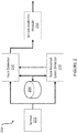
- the sensor control system 200 includes a sensor 202, a database 204, a rate reversal event (RRE) detector 210, a fault detector 220, and optionally includes an accommodation module 250.
- the sensor 202 may be any suitable kind of sensor, whether physical or virtual, and may provide values as analog signals, as digital signals, or as any suitable combination thereof.
- the sensor is a temperature sensor, a pressure sensor, a speed or angular velocity sensor, a torque sensor, a power sensor, or any other suitable sensor.
- the RRE detector 210 is configured for receiving the values produced by the sensor 202.
- the RRE detector 210 is coupled to the sensor 202 via one or more wired and/or wireless connections.
- the RRE detector 210 is provided with the values produced by the sensor 202 by a computing device or other architecture which governs the operation of the sensor 202.
- the sensor 202 is a virtual sensor implemented in a computing device, and the RRE detector 210 is coupled to the computing device for obtaining the values produced by the sensor 202.
- the RRE detector 210 is configured for receiving values from the sensor 202 which are both "in-range” and “out of range”, but the RRE detector 210 analyzes only values from the sensor 202 which are "in-range", that is to say values which are with the normal operating range of the sensor 202.
- the sensor 202 is a temperature sensor producing values which can normally range between 0°C and 50°C: the RRE detector 210 may receive all values, but only consider values between 0°C and 50°C for later analysis.
- the RRE detector 210 is also configured for detecting at least one rate reversal event in the values received from the sensor 202.
- An RRE occurs when the rate-of-change of the values produced by the sensor varies beyond a predetermined variance threshold.
- a RRE is indicated by a rapid fluctuation in the rate-of-change of the first derivative of the values produced by the sensor 202, i.e., variations in the second derivative of the values produced by the sensor 202.
- An RRE is only detected when the variation in the rate-of-change of the values is beyond a predetermined variance threshold.
- the RRE detector 210 is preprogrammed with the variance threshold.
- the RRE detector 210 acquires the variance threshold from the database 204, which may be any suitable storage device or medium.
- the sensor 202 may operate in particularly extreme conditions, and different variance thresholds may be acceptable depending on the particular conditions to which the sensor 202 is exposed. For instance, different variance thresholds may be used depending on the ambient temperature in which the sensor 202 operates, or depending on any other ambient characteristic.
- the RRE detector 210 may detect the RREs either digitally, for example by digitizing the values produced by the sensor 202 and inspecting the values, or via one or more analog means, for example using one or more differentiators.
- the RRE detector 210 is configured for storing indications of RREs in the database 204.
- the RRE detector 210 is also configured for determining a count of RREs during a predetermined time period. For example, the RRE detector 210 determines a count of RREs which take place during any 5 second interval, any 1 second interval, any 0.5 second interval, any 0.1 second interval, or any other suitable interval, appropriate for use with the sensor 202.
- the time period for evaluating a count of RREs may vary with the operating conditions of the sensor 202.
- the RRE detector 210 is communicatively coupled to the fault detector 220 via any suitable wired and/or wireless means.
- the RRE detector 210 and/or the fault detector 220 are configured for assigning a faulty status to the sensor 202 based on the count of RREs exceeding a predetermined limit.
- the RRE detector 210 and/or the fault detector 220 may be preprogrammed with the predetermined limit, or may acquire the limit from the database 204.
- the limit is a number of RREs within the time period, and the RRE detector 210 and/or the fault detector 220 evaluates whether the count of RREs exceeds the number. For example, if more than two RREs occur within the time period of 1 second, the status of the sensor 202 is set to faulty. In other embodiments, the limit is a number of consecutive RREs, which are consecutive in terms of measurements or in terms of their occurrence in consecutive time periods. For example, if more than two RREs occur in three consecutive time periods, the status of the sensor 202 is set to faulty. In some other embodiments, the RRE detector 210 and/or the fault detector 220 determines whether the count of RREs corresponds to a predetermined pattern.
- the RRE detector 210 is configured for evaluating whether the count of RREs exceeds the limit and for reporting to the fault detector 220, which then assigns the faulty status to the sensor 202. In other embodiments, the RRE detector 210 provides the count of RREs to the fault detector 220, and the fault detector 220 evaluates whether the count exceeds the limit. In still further embodiments, the RRE detector 210 stores the count of RREs in the database 204, and the fault detector 220 acquires the count of RREs from the database 204 and evaluates whether to assign the faulty status to the sensor 202 based thereon.
- the faulty status of the sensor 202 is stored in the database 204 by the RRE detector 210 or by the fault detector 220. In other embodiments, the faulty status of the sensor is provided to another control system or entity, for example the accommodation module 250.
- the fault detector 220 is also configured for receiving the values produced by the sensor 202 for evaluating the presence of out-of-range faults, intermittent faults, open circuits, and the like.
- the fault detector 220 is provided with suitable hardware and software for evaluating other types of faults of the sensor 202, as appropriate.
- the RRE detector 210 and/or the fault detector 220 are provided with one or more profiles via the database 204, each of which is associated with a different sensor or type of sensor, and which indicates the relevant variance thresholds, time periods, and/or limits for the sensor.
- a given sensor for example the sensor 202, is provided with different profiles depending on the operating conditions of the sensor 202.
- one or more of the variance thresholds, time periods, and/or limits for the sensor 202 are based on historical data acquired from the sensor 202.
- the limits against which the count of RREs is evaluated may be based on historical data acquired from other sensors like the sensor 202 to take into consideration sensor aging.
- historical data from the sensor 202 can be used to locate the sensor 202 on a sensor aging curve to select an appropriate profile. Still other applications for the historical data are considered.
- the optional accommodation module 250 is configured for being informed of the faulty status of the sensor 202, for example via the fault detector 220, and for performing signal accommodation for the sensor 202.
- signal accommodation is performed by finding and using an alternative source for the values produced by the sensor 202, for example another sensor separate from the sensor 202.
- signal accommodation is performed by applying a smoothing function or other signal processing technique to the values produced by the sensor 202. For example, if the sensor 202 produces a signal with high noise or signal twitch, a smoothing function can be used to produce values with fewer fluctuations due to noise.
- signal accommodation is performed by using a default value for the sensor 202. Still other types of signal accommodation are considered.
- the sensor control system 200 is configured for evaluating sensors according to multiple tiers.
- a first count of RREs during a first time period is found to exceed a first limit
- the sensor 202 is assigned a first faulty status, for example a status indicative of a pending or forthcoming fault.
- the values of the sensor 202 are evaluated to determine whether a subsequent count of RREs during a subsequent time period, which may be separate from the first time period or overlap therewith, exceeds a subsequent limit, at which point the sensor 202 is assigned a second faulty status, indicative of an actual failure of the sensor 202.
- the first and subsequent time periods, variance thresholds, limits, etc. may vary depending on the nature of the sensor 202.
- more than two different fault statuses are considered, and in some embodiments each faulty status is associated with a particular kind of signal accommodation.
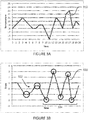
- the sensor 202 is a temperature sensor and the sensor values 310 can normally range between 0°C and 50°C. Although none of the sensor values 310 produced by the sensor 202 are outside the normal range of the sensor 202 (i.e. the sensor values are in-range), the sensor 202 is still faulty.
- the graph of Figure 3B shows the first derivative 320 and RREs 322, surrounded by circles, which are variations in the first derivative 320.
- the portion 324 of the first derivative 320 indicates a time period during which the count of RREs is evaluated: during the time period 324, five RREs occur. If the limit is set at two RREs during any time period, then the occurrence of the five RREs during the time period 324 exceeds the limit, indicating that the sensor 202 is producing in-range faults. The sensor 202 is then assigned a faulty status.
- one or more components of the sensor control system 200 may be implemented by a computing device 410, comprising a processing unit 412 and a memory 414 which has stored therein computer-executable instructions 416.
- the RRE detector 210 and/or the fault detector 220 may be embodied as the computing device 410.
- the processing unit 412 may comprise any suitable devices configured to implement the RRE detector 210 and/or the fault detector 220 such that instructions 416, when executed by the computing device 410 or other programmable apparatus, may cause the functions/acts/steps performed as part of the RRE detector 210 and/or the fault detector 220 as described herein to be executed.
- the processing unit 412 may comprise, for example, any type of general-purpose microprocessor or microcontroller, a digital signal processing (DSP) processor, a central processing unit (CPU), an integrated circuit, a field programmable gate array (FPGA), a reconfigurable processor, other suitably programmed or programmable logic circuits, or any combination thereof.
- DSP digital signal processing
- CPU central processing unit
- FPGA field programmable gate array
- reconfigurable processor other suitably programmed or programmable logic circuits, or any combination thereof.
- the memory 414 may comprise any suitable known or other machine-readable storage medium.
- the memory 414 may comprise non-transitory computer readable storage medium, for example, but not limited to, an electronic, magnetic, optical, electromagnetic, infrared, or semiconductor system, apparatus, or device, or any suitable combination of the foregoing.
- the memory 414 may include a suitable combination of any type of computer memory that is located either internally or externally to device, for example random-access memory (RAM), read-only memory (ROM), compact disc read-only memory (CDROM), electro-optical memory, magnetooptical memory, erasable programmable read-only memory (EPROM), and electrically-erasable programmable read-only memory (EEPROM), Ferroelectric RAM (FRAM) or the like.
- Memory 414 may comprise any storage means (e.g., devices) suitable for retrievably storing machine-readable instructions 416 executable by processing unit 412.
- a method 500 for detecting in-range faults for a sensor for example the sensor 202.
- a plurality of values produced by the sensor 202 are received.
- the values may be received over one or more wired connections, one or more wireless connections, or any suitable combination thereof.
- At step 504 at least one RRE, indicative of a variation in the rate-of-change of the values exceeding a predetermined variance threshold, is detected.
- a count of RREs during a predetermined time period is determined.
- the variance threshold and the time period can be selected based on the nature of the sensor 202, the operating conditions of the sensor 202, or any other suitable conditions.
- a faulty status is assigned to the sensor 202, for example based on the count of rate reversal events exceeding a predetermined limit.
- the limit is associated with the time period, and in other embodiments the limit relates to a predetermined pattern of RREs or a number of consecutive RREs.
- signal accommodation is performed for the sensor 202.
- an alternative healthy sensor is found and used.
- a smoothing function or other signal processing algorithm is applied to the sensor 202. Still other types of signal accommodation are considered.
- the methods and systems for detecting in-range faults for a sensor described herein may be implemented in a high level procedural or object oriented programming or scripting language, or a combination thereof, to communicate with or assist in the operation of a computer system, for example the computing device 410.
- the methods and systems described herein may be implemented in assembly or machine language.
- the language may be a compiled or interpreted language.
- Program code for implementing the methods and systems described herein may be stored on a storage media or a device, for example a ROM, a magnetic disk, an optical disc, a flash drive, or any other suitable storage media or device.
- the program code may be readable by a general or special-purpose programmable computer for configuring and operating the computer when the storage media or device is read by the computer to perform the procedures described herein.
- Embodiments of the methods and systems described herein may also be considered to be implemented by way of a non-transitory computer-readable storage medium having a computer program stored thereon.
- the computer program may comprise computer-readable instructions which cause a computer, or more specifically the processing unit 412 of the computing device 410, to operate in a specific and predefined manner to perform the functions described herein, for example those described in the method 500.
- Computer-executable instructions may be in many forms, including program modules, executed by one or more computers or other devices.
- program modules include routines, programs, objects, components, data structures, etc., that perform particular tasks or implement particular abstract data types.
- functionality of the program modules may be combined or distributed as desired in various embodiments.
Landscapes
- Physics & Mathematics (AREA)
- General Physics & Mathematics (AREA)
- Electromagnetism (AREA)
- Engineering & Computer Science (AREA)
- General Engineering & Computer Science (AREA)
- Testing And Monitoring For Control Systems (AREA)
Abstract
In a method for detecting in-range faults for a sensor (202) of an aircraft engine sensor control system (200), a plurality of in-range values produced by the sensor (202) are received. At least one rate reversal event, indicative of a variation in the rate-of-change of the plurality of in-range values exceeding a predetermined variance threshold, is detected. A count of rate reversal events during a predetermined time period is determined. A faulty status to the sensor (202) is assigned based on the count of rate reversal events exceeding a predetermined limit.
Description
- The present disclosure relates generally to sensors, and more specifically to fault detection for sensors.
- Sensors find use in numerous applications, serving to provide information about environmental conditions, operating parameters, and the like. Sensors are used in all manner of vehicle, industrial machine, electric and electronic appliance, and are often used to provide information which can be used in feedback loops and control systems.
- However, sensors occasionally fail. In some cases, when a sensor fails, it produces values which are outside an expected range for the sensor, and failure can be easily detected. However, in other cases a sensor may produce incorrect values which still lie within an expected range, referred to as "in-range" fault.
- Thus, techniques for detecting in-range faults are needed.
- In accordance an aspect of the present invention, there is provided a method for detecting in-range faults for a sensor of an aircraft engine control system, comprising: receiving a plurality of in-range values produced by the sensor; detecting at least one rate reversal event indicative of a variation in the rate-of-change of the plurality of in-range values exceeding a predetermined variance threshold; determining a count of rate reversal events during a predetermined time period; and assigning a faulty status to the sensor based on the count of rate reversal events exceeding a predetermined limit.
- In some embodiments, assigning a faulty status to the sensor is further based on the at least one rate reversal event corresponding to a predetermined pattern.
- In some embodiments, the limit is a number of rate reversals during the time period.
- In some embodiments, the limit is a number of consecutive rate reversals.
- In some embodiments, the number of consecutive rate reversals is at least 2.
- In some embodiments, the limit is based on historical data acquired from the sensor.
- In some embodiments, assigning a faulty status to the sensor comprises assigning a first faulty status indicative of a pending failure, the method further comprising, after assigning the first faulty status to the sensor: receiving a plurality of subsequent in-range values produced by the sensor; detecting at least one rate reversal event in the subsequent in-range values; determining a subsequent count of rate reversal events during a subsequent predetermined time period; and assigning a second faulty status to the sensor based on the subsequent count of rate reversal events exceeding a predetermined subsequent limit different from the limit, the second faulty status indicative of an actual failure.
- In some embodiments, the time period and the subsequent time period overlap.
- In some embodiments, the method further comprises, after assigning the faulty status to the sensor, performing signal accommodation for the sensor.
- In some embodiments, the sensor is a virtual sensor.
- In accordance with another aspect of the present invention, there is provided an aircraft engine sensor control system communicatively coupled to a sensor, comprising a processing unit and a non-transitory computer-readable memory communicatively coupled to the processing unit. The memory comprises computer-readable program instructions executable by the processing unit for receiving a plurality of in-range values produced by the sensor, detecting at least one rate reversal event indicative of a variation in the rate-of-change of the plurality of in-range values exceeding a predetermined variance threshold, determining a count of rate reversal events during a predetermined time period, and assigning a faulty status to the sensor based on the count of rate reversal events exceeding a predetermined limit.
- In some embodiments, assigning a faulty status to the sensor is further based on the at least one rate reversal event corresponding to a predetermined pattern.
- In some embodiments, the limit is a number of rate reversals during the time period.
- In some embodiments, the limit is a number of consecutive rate reversals.
- In some embodiments, the number of consecutive rate reversals is at least 2.
- In some embodiments, the limit is based on historical data acquired from the sensor.
- In some embodiments, assigning a faulty status to the sensor comprises assigning a first faulty status indicative of a pending failure, wherein the computer-readable program instructions are further executable by the processing unit for, after assigning the first faulty status to the sensor: receiving a plurality of subsequent in-range values produced by the sensor; detecting at least one rate reversal event in the subsequent in-range values; determining a subsequent count of rate reversal events during a subsequent predetermined time period; and assigning a second faulty status to the sensor based on the subsequent count of rate reversal events exceeding a predetermined subsequent limit different from the limit, the second faulty status indicative of an actual failure.
- In some embodiments, the time period and the subsequent time period overlap.
- In some embodiments, the computer-readable program instructions are further executable by the processing unit for, after assigning the faulty status to the sensor, performing signal accommodation for the sensor.
- In some embodiments, the sensor is a virtual sensor.
- Reference is now made to the accompanying figures in which:
-
Figure 1 is a schematic cross-sectional view of an example gas turbine engine; -
Figure 2 is a block diagram of an example sensor control system; -
Figure 3A is a graph showing example sensor values; -
Figure 3B is a graph showing rates-of-change for the sensor values ofFigure 3A ; -
Figure 4 is a block diagram of an example computer system for implementing part or all of the engine control system ofFigure 2 ; and -
Figure 5 is a flowchart illustrating an example method for controlling the engine ofFigure 1 , in accordance with an embodiment. - It will be noted that throughout the appended drawings, like features are identified by like reference numerals.
-
FIG. 1 illustrates agas turbine engine 110 of a type preferably provided for use in subsonic flight, generally comprising in serial flow communication, acompressor section 112 for pressurizing the air, acombustor 114 in which the compressed air is mixed with fuel and ignited for generating an annular stream of hot combustion gases, and aturbine section 116 for extracting energy from the combustion gases. The combustion gases flowing out of thecombustor 114 circulate through theturbine section 116 and are expelled through anexhaust duct 118. Theturbine section 116 includes acompressor turbine 120 in driving engagement with thecompressor section 112 through ahigh pressure shaft 122, and apower turbine 124 in driving engagement with apower shaft 126. Thepower shaft 126 is in driving engagement with anoutput shaft 128 through agearbox 130, which may be a reduction gearbox. Theengine 110 may be equipped with one or more sensors, which may measure pressure, temperature, speed, angular velocity, torque, and the like. - Although illustrated as a turboshaft engine, the
gas turbine engine 110 may alternatively be another type of engine, for example a turbofan engine, also generally comprising in serial flow communication a compressor section, a combustor, and a turbine section, and a fan through which ambient air is propelled. A turboprop engine may also apply. In addition, although the sensor-related applications discussed herein pertain primarily to theengine 110 and flight applications, it should be understood that other uses, such as industrial, commercial, or the like, may apply. - With reference to
Figure 2 , there is shown asensor control system 200 which may be configured for detecting in-range sensor faults. Thesensor control system 200 includes asensor 202, adatabase 204, a rate reversal event (RRE)detector 210, afault detector 220, and optionally includes anaccommodation module 250. Thesensor 202 may be any suitable kind of sensor, whether physical or virtual, and may provide values as analog signals, as digital signals, or as any suitable combination thereof. For example, the sensor is a temperature sensor, a pressure sensor, a speed or angular velocity sensor, a torque sensor, a power sensor, or any other suitable sensor. - The
RRE detector 210 is configured for receiving the values produced by thesensor 202. In some embodiments, theRRE detector 210 is coupled to thesensor 202 via one or more wired and/or wireless connections. In other embodiments, theRRE detector 210 is provided with the values produced by thesensor 202 by a computing device or other architecture which governs the operation of thesensor 202. For example, thesensor 202 is a virtual sensor implemented in a computing device, and theRRE detector 210 is coupled to the computing device for obtaining the values produced by thesensor 202. In some embodiments, theRRE detector 210 is configured for receiving values from thesensor 202 which are both "in-range" and "out of range", but theRRE detector 210 analyzes only values from thesensor 202 which are "in-range", that is to say values which are with the normal operating range of thesensor 202. For example, thesensor 202 is a temperature sensor producing values which can normally range between 0°C and 50°C: theRRE detector 210 may receive all values, but only consider values between 0°C and 50°C for later analysis. - The
RRE detector 210 is also configured for detecting at least one rate reversal event in the values received from thesensor 202. An RRE occurs when the rate-of-change of the values produced by the sensor varies beyond a predetermined variance threshold. Put differently, a RRE is indicated by a rapid fluctuation in the rate-of-change of the first derivative of the values produced by thesensor 202, i.e., variations in the second derivative of the values produced by thesensor 202. An RRE is only detected when the variation in the rate-of-change of the values is beyond a predetermined variance threshold. In some embodiments, theRRE detector 210 is preprogrammed with the variance threshold. In other embodiments, theRRE detector 210 acquires the variance threshold from thedatabase 204, which may be any suitable storage device or medium. For example, thesensor 202 may operate in particularly extreme conditions, and different variance thresholds may be acceptable depending on the particular conditions to which thesensor 202 is exposed. For instance, different variance thresholds may be used depending on the ambient temperature in which thesensor 202 operates, or depending on any other ambient characteristic. - The
RRE detector 210 may detect the RREs either digitally, for example by digitizing the values produced by thesensor 202 and inspecting the values, or via one or more analog means, for example using one or more differentiators. In some embodiments, theRRE detector 210 is configured for storing indications of RREs in thedatabase 204. - The
RRE detector 210 is also configured for determining a count of RREs during a predetermined time period. For example, theRRE detector 210 determines a count of RREs which take place during any 5 second interval, any 1 second interval, any 0.5 second interval, any 0.1 second interval, or any other suitable interval, appropriate for use with thesensor 202. The time period for evaluating a count of RREs may vary with the operating conditions of thesensor 202. - The
RRE detector 210 is communicatively coupled to thefault detector 220 via any suitable wired and/or wireless means. TheRRE detector 210 and/or thefault detector 220 are configured for assigning a faulty status to thesensor 202 based on the count of RREs exceeding a predetermined limit. TheRRE detector 210 and/or thefault detector 220 may be preprogrammed with the predetermined limit, or may acquire the limit from thedatabase 204. - In some embodiments, the limit is a number of RREs within the time period, and the
RRE detector 210 and/or thefault detector 220 evaluates whether the count of RREs exceeds the number. For example, if more than two RREs occur within the time period of 1 second, the status of thesensor 202 is set to faulty. In other embodiments, the limit is a number of consecutive RREs, which are consecutive in terms of measurements or in terms of their occurrence in consecutive time periods. For example, if more than two RREs occur in three consecutive time periods, the status of thesensor 202 is set to faulty. In some other embodiments, theRRE detector 210 and/or thefault detector 220 determines whether the count of RREs corresponds to a predetermined pattern. For example, if RREs occur in every second time period, or every third time period, the status of thesensor 202 is set to faulty. It should be noted that the specific values used in the examples herein are merely examples, and other numerical values may be substituted therefor. - In some embodiments, the
RRE detector 210 is configured for evaluating whether the count of RREs exceeds the limit and for reporting to thefault detector 220, which then assigns the faulty status to thesensor 202. In other embodiments, theRRE detector 210 provides the count of RREs to thefault detector 220, and thefault detector 220 evaluates whether the count exceeds the limit. In still further embodiments, theRRE detector 210 stores the count of RREs in thedatabase 204, and thefault detector 220 acquires the count of RREs from thedatabase 204 and evaluates whether to assign the faulty status to thesensor 202 based thereon. - In some embodiments, the faulty status of the
sensor 202 is stored in thedatabase 204 by theRRE detector 210 or by thefault detector 220. In other embodiments, the faulty status of the sensor is provided to another control system or entity, for example theaccommodation module 250. - In some embodiments, the
fault detector 220 is also configured for receiving the values produced by thesensor 202 for evaluating the presence of out-of-range faults, intermittent faults, open circuits, and the like. Thefault detector 220 is provided with suitable hardware and software for evaluating other types of faults of thesensor 202, as appropriate. - In some embodiments, the
RRE detector 210 and/or thefault detector 220 are provided with one or more profiles via thedatabase 204, each of which is associated with a different sensor or type of sensor, and which indicates the relevant variance thresholds, time periods, and/or limits for the sensor. In some embodiments, a given sensor, for example thesensor 202, is provided with different profiles depending on the operating conditions of thesensor 202. - In some embodiments, one or more of the variance thresholds, time periods, and/or limits for the
sensor 202 are based on historical data acquired from thesensor 202. For example, the limits against which the count of RREs is evaluated may be based on historical data acquired from other sensors like thesensor 202 to take into consideration sensor aging. In addition, historical data from thesensor 202 can be used to locate thesensor 202 on a sensor aging curve to select an appropriate profile. Still other applications for the historical data are considered. - The
optional accommodation module 250 is configured for being informed of the faulty status of thesensor 202, for example via thefault detector 220, and for performing signal accommodation for thesensor 202. In some embodiments, signal accommodation is performed by finding and using an alternative source for the values produced by thesensor 202, for example another sensor separate from thesensor 202. In other embodiments, signal accommodation is performed by applying a smoothing function or other signal processing technique to the values produced by thesensor 202. For example, if thesensor 202 produces a signal with high noise or signal twitch, a smoothing function can be used to produce values with fewer fluctuations due to noise. In still other embodiments, signal accommodation is performed by using a default value for thesensor 202. Still other types of signal accommodation are considered. - In some embodiments, the
sensor control system 200 is configured for evaluating sensors according to multiple tiers. When a first count of RREs during a first time period is found to exceed a first limit, thesensor 202 is assigned a first faulty status, for example a status indicative of a pending or forthcoming fault. Then, the values of thesensor 202 are evaluated to determine whether a subsequent count of RREs during a subsequent time period, which may be separate from the first time period or overlap therewith, exceeds a subsequent limit, at which point thesensor 202 is assigned a second faulty status, indicative of an actual failure of thesensor 202. The first and subsequent time periods, variance thresholds, limits, etc., may vary depending on the nature of thesensor 202. In addition, more than two different fault statuses are considered, and in some embodiments each faulty status is associated with a particular kind of signal accommodation. - With reference to
Figures 3A and 3B , there are shown example graphs ofsensor values 310 and an associated first derivative 320 showing RREs, respectively. In the example ofFigures 3A and 3B , thesensor 202 is a temperature sensor and the sensor values 310 can normally range between 0°C and 50°C. Although none of the sensor values 310 produced by thesensor 202 are outside the normal range of the sensor 202 (i.e. the sensor values are in-range), thesensor 202 is still faulty. - The graph of
Figure 3B shows thefirst derivative 320 andRREs 322, surrounded by circles, which are variations in thefirst derivative 320. In addition, theportion 324 of thefirst derivative 320 indicates a time period during which the count of RREs is evaluated: during thetime period 324, five RREs occur. If the limit is set at two RREs during any time period, then the occurrence of the five RREs during thetime period 324 exceeds the limit, indicating that thesensor 202 is producing in-range faults. Thesensor 202 is then assigned a faulty status. - With reference to
Figure 4 , one or more components of thesensor control system 200, for instance theRRE detector 210 and/or thefault detector 220, may be implemented by acomputing device 410, comprising aprocessing unit 412 and amemory 414 which has stored therein computer-executable instructions 416. For example, theRRE detector 210 and/or thefault detector 220 may be embodied as thecomputing device 410. Theprocessing unit 412 may comprise any suitable devices configured to implement theRRE detector 210 and/or thefault detector 220 such thatinstructions 416, when executed by thecomputing device 410 or other programmable apparatus, may cause the functions/acts/steps performed as part of theRRE detector 210 and/or thefault detector 220 as described herein to be executed. Theprocessing unit 412 may comprise, for example, any type of general-purpose microprocessor or microcontroller, a digital signal processing (DSP) processor, a central processing unit (CPU), an integrated circuit, a field programmable gate array (FPGA), a reconfigurable processor, other suitably programmed or programmable logic circuits, or any combination thereof. - The
memory 414 may comprise any suitable known or other machine-readable storage medium. Thememory 414 may comprise non-transitory computer readable storage medium, for example, but not limited to, an electronic, magnetic, optical, electromagnetic, infrared, or semiconductor system, apparatus, or device, or any suitable combination of the foregoing. Thememory 414 may include a suitable combination of any type of computer memory that is located either internally or externally to device, for example random-access memory (RAM), read-only memory (ROM), compact disc read-only memory (CDROM), electro-optical memory, magnetooptical memory, erasable programmable read-only memory (EPROM), and electrically-erasable programmable read-only memory (EEPROM), Ferroelectric RAM (FRAM) or the like.Memory 414 may comprise any storage means (e.g., devices) suitable for retrievably storing machine-readable instructions 416 executable by processingunit 412. - With reference to
Figure 5 , there is shown amethod 500 for detecting in-range faults for a sensor, for example thesensor 202. Atstep 502, a plurality of values produced by thesensor 202 are received. The values may be received over one or more wired connections, one or more wireless connections, or any suitable combination thereof. - At
step 504, at least one RRE, indicative of a variation in the rate-of-change of the values exceeding a predetermined variance threshold, is detected. Atstep 506, a count of RREs during a predetermined time period is determined. The variance threshold and the time period can be selected based on the nature of thesensor 202, the operating conditions of thesensor 202, or any other suitable conditions. - At
decision step 508, a determination is made regarding whether the count of rate reversal events exceeds a predetermined limit. If the count of rate reversal events does not exceed the predetermined limit, themethod 500 returns to some previous step, forexample step 502. If the count of rate reversal events does exceed the predetermined limit, themethod 500 proceeds to step 510. - At
step 510, a faulty status is assigned to thesensor 202, for example based on the count of rate reversal events exceeding a predetermined limit. In some embodiments the limit is associated with the time period, and in other embodiments the limit relates to a predetermined pattern of RREs or a number of consecutive RREs. - Optionally, at
step 512, signal accommodation is performed for thesensor 202. In some embodiments, an alternative healthy sensor is found and used. In other embodiments, a smoothing function or other signal processing algorithm is applied to thesensor 202. Still other types of signal accommodation are considered. - The methods and systems for detecting in-range faults for a sensor described herein may be implemented in a high level procedural or object oriented programming or scripting language, or a combination thereof, to communicate with or assist in the operation of a computer system, for example the
computing device 410. Alternatively, the methods and systems described herein may be implemented in assembly or machine language. The language may be a compiled or interpreted language. Program code for implementing the methods and systems described herein may be stored on a storage media or a device, for example a ROM, a magnetic disk, an optical disc, a flash drive, or any other suitable storage media or device. The program code may be readable by a general or special-purpose programmable computer for configuring and operating the computer when the storage media or device is read by the computer to perform the procedures described herein. Embodiments of the methods and systems described herein may also be considered to be implemented by way of a non-transitory computer-readable storage medium having a computer program stored thereon. The computer program may comprise computer-readable instructions which cause a computer, or more specifically theprocessing unit 412 of thecomputing device 410, to operate in a specific and predefined manner to perform the functions described herein, for example those described in themethod 500. - Computer-executable instructions may be in many forms, including program modules, executed by one or more computers or other devices. Generally, program modules include routines, programs, objects, components, data structures, etc., that perform particular tasks or implement particular abstract data types. Typically the functionality of the program modules may be combined or distributed as desired in various embodiments.
- The above description is meant to be exemplary only, and one skilled in the art will recognize that changes may be made to the embodiments described without departing from the scope of the invention disclosed. Still other modifications which fall within the scope of the present invention will be apparent to those skilled in the art, in light of a review of this disclosure.
- Various aspects of the methods and systems described herein may be used alone, in combination, or in a variety of arrangements not specifically discussed in the embodiments described in the foregoing and is therefore not limited in its application to the details and arrangement of components set forth in the foregoing description or illustrated in the drawings. For example, aspects described in one embodiment may be combined in any manner with aspects described in other embodiments. Although particular embodiments have been shown and described, it will be apparent to those skilled in the art that changes and modifications may be made without departing from this invention in its broader aspects. The scope of the following claims should not be limited by the embodiments set forth in the examples, but should be given the broadest reasonable interpretation consistent with the description as a whole.
Claims (15)
- A method (500) for detecting in-range faults for a sensor (202) of an aircraft engine sensor control system (200), comprising:receiving a plurality of in-range values produced by the sensor (202);detecting at least one rate reversal event indicative of a variation in the rate-of-change of the plurality of in-range values exceeding a predetermined variance threshold;determining a count of rate reversal events during a predetermined time period; andassigning a faulty status to the sensor (202) based on the count of rate reversal events exceeding a predetermined limit.
- The method of claim 1, wherein assigning a faulty status to the sensor (202) is further based on the at least one rate reversal event corresponding to a predetermined pattern.
- The method of claim 1 or 2, wherein the limit is a number of rate reversals during the time period.
- The method of claim 1 or 2, wherein the limit is a number of consecutive rate reversals, and preferably wherein the number of consecutive rate reversals is at least 2.
- The method of claim 1 or 2, wherein the limit is based on historical data acquired from the sensor (202).
- The method of any preceding claim, wherein assigning a faulty status to the sensor (202) comprises assigning a first faulty status indicative of a pending failure, further comprising, after assigning the first faulty status to the sensor (202):receiving a plurality of subsequent in-range values produced by the sensor (202);detecting at least one rate reversal event in the subsequent in-range values;determining a subsequent count of rate reversal events during a subsequent predetermined time period; andassigning a second faulty status to the sensor (202) based on the subsequent count of rate reversal events exceeding a predetermined subsequent limit different from the limit, the second faulty status indicative of an actual failure,preferably wherein the time period and the subsequent time period overlap.
- The method of any preceding claim, further comprising, after assigning the faulty status to the sensor (202), performing signal accommodation for the sensor (202).
- An aircraft engine sensor control system (200) communicatively coupled to a sensor (202), comprising:a processing unit (412); anda non-transitory computer-readable memory (414) communicatively coupled to the processing unit (412) and comprising computer-readable program instructions (416) executable by the processing unit (412) for:receiving a plurality of in-range values produced by the sensor (202);detecting at least one rate reversal event indicative of a variation in the rate-of-change of the plurality of in-range values exceeding a predetermined variance threshold;determining a count of rate reversal events during a predetermined time period; andassigning a faulty status to the sensor (202) based on the count of rate reversal events exceeding a predetermined limit.
- The system of claim 8, wherein assigning a faulty status to the sensor (202) is further based on the at least one rate reversal event corresponding to a predetermined pattern.
- The system of claim 8 or 9, wherein the limit is a number of rate reversals during the time period.
- The system of claim 8 or 9, wherein the limit is a number of consecutive rate reversals, and preferably wherein the number of consecutive rate reversals is at least 2.
- The system of claim 8 or 9, wherein the limit is based on historical data acquired from the sensor (202).
- The system of any of claims 8 to 12, wherein assigning a faulty status to the sensor (202) comprises assigning a first faulty status indicative of a pending failure, wherein the computer-readable program instructions (416) are further executable by the processing unit (412) for, after assigning the first faulty status to the sensor (202):receiving a plurality of subsequent in-range values produced by the sensor (202);detecting at least one rate reversal event in the subsequent in-range values;determining a subsequent count of rate reversal events during a subsequent predetermined time period; andassigning a second faulty status to the sensor (202) based on the subsequent count of rate reversal events exceeding a predetermined subsequent limit different from the limit, the second faulty status indicative of an actual failure,preferably wherein the time period and the subsequent time period overlap.
- The system of any of claims 8 to 13, wherein the computer-readable program instructions (416) are further executable by the processing unit (412) for, after assigning the faulty status to the sensor (202), performing signal accommodation for the sensor (202).
- The system of any of claims 8 to 14, wherein the sensor (202) is a virtual sensor (202).
Applications Claiming Priority (1)
| Application Number | Priority Date | Filing Date | Title |
|---|---|---|---|
| US15/817,156 US20190154754A1 (en) | 2017-11-17 | 2017-11-17 | In-range sensor fault detection |
Publications (1)
| Publication Number | Publication Date |
|---|---|
| EP3486613A1 true EP3486613A1 (en) | 2019-05-22 |
Family
ID=64402011
Family Applications (1)
| Application Number | Title | Priority Date | Filing Date |
|---|---|---|---|
| EP18207110.0A Withdrawn EP3486613A1 (en) | 2017-11-17 | 2018-11-19 | In-range sensor fault detection |
Country Status (3)
| Country | Link |
|---|---|
| US (1) | US20190154754A1 (en) |
| EP (1) | EP3486613A1 (en) |
| CA (1) | CA3024647A1 (en) |
Families Citing this family (2)
| Publication number | Priority date | Publication date | Assignee | Title |
|---|---|---|---|---|
| WO2019193714A1 (en) * | 2018-04-05 | 2019-10-10 | 三菱電機株式会社 | Air conditioner |
| CN112145369B (en) * | 2019-06-28 | 2022-09-20 | 北京金风科创风电设备有限公司 | Fault diagnosis method and device for wind measuring system of wind generating set |
Citations (3)
| Publication number | Priority date | Publication date | Assignee | Title |
|---|---|---|---|---|
| US5394341A (en) * | 1993-03-25 | 1995-02-28 | Ford Motor Company | Apparatus for detecting the failure of a sensor |
| DE102011002572A1 (en) * | 2011-01-12 | 2012-07-12 | Robert Bosch Gmbh | Method for evaluating sensor signal of inertial sensor used in vehicle, involves determining replacement value for sensor signal based on preceding values of senor signal |
| US20140100816A1 (en) * | 2012-10-10 | 2014-04-10 | Honeywell Intl. Inc. | Filter activation and deactivation based on comparative rates |
Family Cites Families (5)
| Publication number | Priority date | Publication date | Assignee | Title |
|---|---|---|---|---|
| DE10145485B4 (en) * | 2001-09-14 | 2007-12-27 | Siemens Ag | Method and device for diagnosing a sensor |
| US7900616B2 (en) * | 2007-12-12 | 2011-03-08 | Denso Corporation | Exhaust gas oxygen sensor monitoring |
| US7870440B2 (en) * | 2008-03-14 | 2011-01-11 | Oracle America, Inc. | Method and apparatus for detecting multiple anomalies in a cluster of components |
| JP6059046B2 (en) * | 2013-03-04 | 2017-01-11 | アズビル株式会社 | Defect detection system and defect detection method |
| US9435284B2 (en) * | 2014-12-15 | 2016-09-06 | Caterpillar Inc. | In-range sensor fault diagnostic system and method |
-
2017
- 2017-11-17 US US15/817,156 patent/US20190154754A1/en not_active Abandoned
-
2018
- 2018-11-19 CA CA3024647A patent/CA3024647A1/en not_active Abandoned
- 2018-11-19 EP EP18207110.0A patent/EP3486613A1/en not_active Withdrawn
Patent Citations (3)
| Publication number | Priority date | Publication date | Assignee | Title |
|---|---|---|---|---|
| US5394341A (en) * | 1993-03-25 | 1995-02-28 | Ford Motor Company | Apparatus for detecting the failure of a sensor |
| DE102011002572A1 (en) * | 2011-01-12 | 2012-07-12 | Robert Bosch Gmbh | Method for evaluating sensor signal of inertial sensor used in vehicle, involves determining replacement value for sensor signal based on preceding values of senor signal |
| US20140100816A1 (en) * | 2012-10-10 | 2014-04-10 | Honeywell Intl. Inc. | Filter activation and deactivation based on comparative rates |
Also Published As
| Publication number | Publication date |
|---|---|
| US20190154754A1 (en) | 2019-05-23 |
| CA3024647A1 (en) | 2019-05-27 |
Similar Documents
| Publication | Publication Date | Title |
|---|---|---|
| JP5144998B2 (en) | Aerodynamic stability management system and its controller | |
| EP2175336A1 (en) | Adaptive Performance Model and Methods for System Maintenance | |
| US11326468B2 (en) | Methods and systems for operating a gas turbine engine | |
| US11396823B2 (en) | System and method for monitoring temperature of a gas turbine engine | |
| CN113727913B (en) | System for monitoring the health of a helicopter | |
| US9996078B1 (en) | Pre-emptive fault detection through advanced signal analysis | |
| EP3546914A1 (en) | Method and system for detecting shear of a rotating shaft | |
| CN113007121B (en) | System and method for detecting performance degradation of a control valve | |
| CN104454606B (en) | Compressor blade monitoring system | |
| US11615656B2 (en) | Method and system for diagnosing an engine or an aircraft | |
| US20190154754A1 (en) | In-range sensor fault detection | |
| CA3067893A1 (en) | Method and system for detecting fan blade structural failure | |
| US10400624B2 (en) | System and method for planning engine borescope inspections based on FOD probability estimation | |
| US11667392B2 (en) | Method and system for operating a rotorcraft engine | |
| US20210052999A1 (en) | Method and system for monitoring a fluid system configured to operate with a filter | |
| EP3409926B1 (en) | Method and system for detecting a high temperature condition of a gas turbine | |
| US10082243B1 (en) | Method and system for inlet blockage detection | |
| US20180079520A1 (en) | Inclement weather detection for aircraft engines | |
| US11047309B2 (en) | Method and system for detecting an abnormal engine start | |
| US20210115808A1 (en) | Health monitoring for multi-channel pressure transducers | |
| US10013814B2 (en) | Diagnosis of aircraft gas turbine engines | |
| US11235885B2 (en) | Method and system for determining a throttle position of an aircraft | |
| US11499883B2 (en) | System and method for monitoring a pressure transducer | |
| CA3037770A1 (en) | Method and system for detecting shear of a rotating shaft | |
| EP3626947A1 (en) | System and methods of determining acceleration of a shaft |
Legal Events
| Date | Code | Title | Description |
|---|---|---|---|
| PUAI | Public reference made under article 153(3) epc to a published international application that has entered the european phase |
Free format text: ORIGINAL CODE: 0009012 |
|
| STAA | Information on the status of an ep patent application or granted ep patent |
Free format text: STATUS: THE APPLICATION HAS BEEN PUBLISHED |
|
| AK | Designated contracting states |
Kind code of ref document: A1 Designated state(s): AL AT BE BG CH CY CZ DE DK EE ES FI FR GB GR HR HU IE IS IT LI LT LU LV MC MK MT NL NO PL PT RO RS SE SI SK SM TR |
|
| AX | Request for extension of the european patent |
Extension state: BA ME |
|
| STAA | Information on the status of an ep patent application or granted ep patent |
Free format text: STATUS: THE APPLICATION IS DEEMED TO BE WITHDRAWN |
|
| 18D | Application deemed to be withdrawn |
Effective date: 20191123 |