EP3486568A1 - Method of controlling fuel injection in a reheat combustor for a cambustor assembly of a gas turbine and associated reheat combustor - Google Patents
Method of controlling fuel injection in a reheat combustor for a cambustor assembly of a gas turbine and associated reheat combustor Download PDFInfo
- Publication number
- EP3486568A1 EP3486568A1 EP18207407.0A EP18207407A EP3486568A1 EP 3486568 A1 EP3486568 A1 EP 3486568A1 EP 18207407 A EP18207407 A EP 18207407A EP 3486568 A1 EP3486568 A1 EP 3486568A1
- Authority
- EP
- European Patent Office
- Prior art keywords
- injection
- fuel
- combustor
- gas flow
- fuel supply
- Prior art date
- Legal status (The legal status is an assumption and is not a legal conclusion. Google has not performed a legal analysis and makes no representation as to the accuracy of the status listed.)
- Granted
Links
- 238000002347 injection Methods 0.000 title claims abstract description 103
- 239000007924 injection Substances 0.000 title claims abstract description 103
- 239000000446 fuel Substances 0.000 title claims abstract description 86
- 238000000034 method Methods 0.000 title claims abstract description 13
- 238000009828 non-uniform distribution Methods 0.000 claims abstract description 9
- 238000002485 combustion reaction Methods 0.000 claims description 21
- 238000009826 distribution Methods 0.000 claims description 12
- 238000011144 upstream manufacturing Methods 0.000 claims description 9
- 239000003570 air Substances 0.000 description 13
- 230000010349 pulsation Effects 0.000 description 10
- 239000000203 mixture Substances 0.000 description 5
- 238000010586 diagram Methods 0.000 description 3
- 239000012530 fluid Substances 0.000 description 2
- 239000011159 matrix material Substances 0.000 description 2
- 239000012080 ambient air Substances 0.000 description 1
- 230000002349 favourable effect Effects 0.000 description 1
- 238000012986 modification Methods 0.000 description 1
- 230000004048 modification Effects 0.000 description 1
- 230000000284 resting effect Effects 0.000 description 1
- 230000007704 transition Effects 0.000 description 1
Images


Classifications
-
- F—MECHANICAL ENGINEERING; LIGHTING; HEATING; WEAPONS; BLASTING
- F02—COMBUSTION ENGINES; HOT-GAS OR COMBUSTION-PRODUCT ENGINE PLANTS
- F02C—GAS-TURBINE PLANTS; AIR INTAKES FOR JET-PROPULSION PLANTS; CONTROLLING FUEL SUPPLY IN AIR-BREATHING JET-PROPULSION PLANTS
- F02C9/00—Controlling gas-turbine plants; Controlling fuel supply in air- breathing jet-propulsion plants
- F02C9/26—Control of fuel supply
-
- F—MECHANICAL ENGINEERING; LIGHTING; HEATING; WEAPONS; BLASTING
- F02—COMBUSTION ENGINES; HOT-GAS OR COMBUSTION-PRODUCT ENGINE PLANTS
- F02C—GAS-TURBINE PLANTS; AIR INTAKES FOR JET-PROPULSION PLANTS; CONTROLLING FUEL SUPPLY IN AIR-BREATHING JET-PROPULSION PLANTS
- F02C7/00—Features, components parts, details or accessories, not provided for in, or of interest apart form groups F02C1/00 - F02C6/00; Air intakes for jet-propulsion plants
- F02C7/22—Fuel supply systems
- F02C7/228—Dividing fuel between various burners
-
- F—MECHANICAL ENGINEERING; LIGHTING; HEATING; WEAPONS; BLASTING
- F02—COMBUSTION ENGINES; HOT-GAS OR COMBUSTION-PRODUCT ENGINE PLANTS
- F02C—GAS-TURBINE PLANTS; AIR INTAKES FOR JET-PROPULSION PLANTS; CONTROLLING FUEL SUPPLY IN AIR-BREATHING JET-PROPULSION PLANTS
- F02C9/00—Controlling gas-turbine plants; Controlling fuel supply in air- breathing jet-propulsion plants
- F02C9/26—Control of fuel supply
- F02C9/263—Control of fuel supply by means of fuel metering valves
-
- F—MECHANICAL ENGINEERING; LIGHTING; HEATING; WEAPONS; BLASTING
- F23—COMBUSTION APPARATUS; COMBUSTION PROCESSES
- F23C—METHODS OR APPARATUS FOR COMBUSTION USING FLUID FUEL OR SOLID FUEL SUSPENDED IN A CARRIER GAS OR AIR
- F23C6/00—Combustion apparatus characterised by the combination of two or more combustion chambers or combustion zones, e.g. for staged combustion
- F23C6/04—Combustion apparatus characterised by the combination of two or more combustion chambers or combustion zones, e.g. for staged combustion in series connection
- F23C6/042—Combustion apparatus characterised by the combination of two or more combustion chambers or combustion zones, e.g. for staged combustion in series connection with fuel supply in stages
-
- F—MECHANICAL ENGINEERING; LIGHTING; HEATING; WEAPONS; BLASTING
- F23—COMBUSTION APPARATUS; COMBUSTION PROCESSES
- F23D—BURNERS
- F23D14/00—Burners for combustion of a gas, e.g. of a gas stored under pressure as a liquid
- F23D14/46—Details, e.g. noise reduction means
- F23D14/62—Mixing devices; Mixing tubes
-
- F—MECHANICAL ENGINEERING; LIGHTING; HEATING; WEAPONS; BLASTING
- F23—COMBUSTION APPARATUS; COMBUSTION PROCESSES
- F23D—BURNERS
- F23D14/00—Burners for combustion of a gas, e.g. of a gas stored under pressure as a liquid
- F23D14/46—Details, e.g. noise reduction means
- F23D14/70—Baffles or like flow-disturbing devices
-
- F—MECHANICAL ENGINEERING; LIGHTING; HEATING; WEAPONS; BLASTING
- F23—COMBUSTION APPARATUS; COMBUSTION PROCESSES
- F23R—GENERATING COMBUSTION PRODUCTS OF HIGH PRESSURE OR HIGH VELOCITY, e.g. GAS-TURBINE COMBUSTION CHAMBERS
- F23R3/00—Continuous combustion chambers using liquid or gaseous fuel
- F23R3/02—Continuous combustion chambers using liquid or gaseous fuel characterised by the air-flow or gas-flow configuration
- F23R3/04—Air inlet arrangements
- F23R3/10—Air inlet arrangements for primary air
- F23R3/12—Air inlet arrangements for primary air inducing a vortex
-
- F—MECHANICAL ENGINEERING; LIGHTING; HEATING; WEAPONS; BLASTING
- F23—COMBUSTION APPARATUS; COMBUSTION PROCESSES
- F23R—GENERATING COMBUSTION PRODUCTS OF HIGH PRESSURE OR HIGH VELOCITY, e.g. GAS-TURBINE COMBUSTION CHAMBERS
- F23R3/00—Continuous combustion chambers using liquid or gaseous fuel
- F23R3/02—Continuous combustion chambers using liquid or gaseous fuel characterised by the air-flow or gas-flow configuration
- F23R3/16—Continuous combustion chambers using liquid or gaseous fuel characterised by the air-flow or gas-flow configuration with devices inside the flame tube or the combustion chamber to influence the air or gas flow
-
- F—MECHANICAL ENGINEERING; LIGHTING; HEATING; WEAPONS; BLASTING
- F23—COMBUSTION APPARATUS; COMBUSTION PROCESSES
- F23R—GENERATING COMBUSTION PRODUCTS OF HIGH PRESSURE OR HIGH VELOCITY, e.g. GAS-TURBINE COMBUSTION CHAMBERS
- F23R3/00—Continuous combustion chambers using liquid or gaseous fuel
- F23R3/28—Continuous combustion chambers using liquid or gaseous fuel characterised by the fuel supply
- F23R3/286—Continuous combustion chambers using liquid or gaseous fuel characterised by the fuel supply having fuel-air premixing devices
-
- F—MECHANICAL ENGINEERING; LIGHTING; HEATING; WEAPONS; BLASTING
- F23—COMBUSTION APPARATUS; COMBUSTION PROCESSES
- F23R—GENERATING COMBUSTION PRODUCTS OF HIGH PRESSURE OR HIGH VELOCITY, e.g. GAS-TURBINE COMBUSTION CHAMBERS
- F23R3/00—Continuous combustion chambers using liquid or gaseous fuel
- F23R3/28—Continuous combustion chambers using liquid or gaseous fuel characterised by the fuel supply
- F23R3/34—Feeding into different combustion zones
-
- F—MECHANICAL ENGINEERING; LIGHTING; HEATING; WEAPONS; BLASTING
- F23—COMBUSTION APPARATUS; COMBUSTION PROCESSES
- F23R—GENERATING COMBUSTION PRODUCTS OF HIGH PRESSURE OR HIGH VELOCITY, e.g. GAS-TURBINE COMBUSTION CHAMBERS
- F23R3/00—Continuous combustion chambers using liquid or gaseous fuel
- F23R3/28—Continuous combustion chambers using liquid or gaseous fuel characterised by the fuel supply
- F23R3/36—Supply of different fuels
-
- F—MECHANICAL ENGINEERING; LIGHTING; HEATING; WEAPONS; BLASTING
- F23—COMBUSTION APPARATUS; COMBUSTION PROCESSES
- F23C—METHODS OR APPARATUS FOR COMBUSTION USING FLUID FUEL OR SOLID FUEL SUSPENDED IN A CARRIER GAS OR AIR
- F23C2900/00—Special features of, or arrangements for combustion apparatus using fluid fuels or solid fuels suspended in air; Combustion processes therefor
- F23C2900/07001—Air swirling vanes incorporating fuel injectors
-
- F—MECHANICAL ENGINEERING; LIGHTING; HEATING; WEAPONS; BLASTING
- F23—COMBUSTION APPARATUS; COMBUSTION PROCESSES
- F23D—BURNERS
- F23D2204/00—Burners adapted for simultaneous or alternative combustion having more than one fuel supply
- F23D2204/10—Burners adapted for simultaneous or alternative combustion having more than one fuel supply gaseous and liquid fuel
-
- F—MECHANICAL ENGINEERING; LIGHTING; HEATING; WEAPONS; BLASTING
- F23—COMBUSTION APPARATUS; COMBUSTION PROCESSES
- F23D—BURNERS
- F23D2900/00—Special features of, or arrangements for burners using fluid fuels or solid fuels suspended in a carrier gas
- F23D2900/21—Burners specially adapted for a particular use
- F23D2900/21003—Burners specially adapted for a particular use for heating or re-burning air or gas in a duct
-
- F—MECHANICAL ENGINEERING; LIGHTING; HEATING; WEAPONS; BLASTING
- F23—COMBUSTION APPARATUS; COMBUSTION PROCESSES
- F23R—GENERATING COMBUSTION PRODUCTS OF HIGH PRESSURE OR HIGH VELOCITY, e.g. GAS-TURBINE COMBUSTION CHAMBERS
- F23R2900/00—Special features of, or arrangements for continuous combustion chambers; Combustion processes therefor
- F23R2900/00014—Reducing thermo-acoustic vibrations by passive means, e.g. by Helmholtz resonators
-
- F—MECHANICAL ENGINEERING; LIGHTING; HEATING; WEAPONS; BLASTING
- F23—COMBUSTION APPARATUS; COMBUSTION PROCESSES
- F23R—GENERATING COMBUSTION PRODUCTS OF HIGH PRESSURE OR HIGH VELOCITY, e.g. GAS-TURBINE COMBUSTION CHAMBERS
- F23R2900/00—Special features of, or arrangements for continuous combustion chambers; Combustion processes therefor
- F23R2900/03341—Sequential combustion chambers or burners
Definitions
- the present invention relates to a method of controlling fuel injection in a reheat combustor for a sequential gas turbine for power plants.
- the present invention relates to controlling fluid supply to reheat injection nozzles so as to minimize thermoacoustic pulsations.
- a gas turbine for power plants comprises an upstream compressor, a combustor assembly and a downstream turbine.
- the turbine includes a rotor comprising a compressor section and a turbine section.
- downstream and upstream refer to the direction of the main gas flow passing through the gas turbine.
- the compressor comprises an inlet supplied with air and a plurality of blades compressing the passing air.
- the compressed air leaving the compressor flows into a plenum, i.e. a closed volume, and from there into the combustor, where the compressed air is mixed with at least one fuel.
- the mixture of fuel and compressed air flows into a combustion chamber inside the combustor where this mixture is combusted.
- the resulting hot gas leaves the combustor and is expanded in the turbine, producing mechanical work on the rotor.
- gas turbines which comprise a combustor assembly performing a sequential combustion cycle.
- a sequential combustor assembly comprises two combustors in series, wherein each combustor is provided with a respective burner and combustion chamber. Following the main gas flow direction, the upstream combustor is called “premix” combustor and is fed by the compressed air. The downstream combustor is called “sequential” or “reheat” combustor and is fed by the hot gas leaving the first combustion chamber.
- this first configuration includes the compressor, the premix combustor, the high-pressure turbine, the reheat combustor and a low-pressure turbine.
- the premix and the reheat combustor are arranged directly one downstream the other inside a common casing, in particular a can-shaped casing, and no high-pressure turbine is used.
- a plurality of can combustors are provided, which are distributed around the turbine axis.
- Each can combustor is provided with a hot gas flow channel, a reheat burner housed in the flow channel, and a reheat combustion chamber into which the flow channel opens downstream of the reheat burner.
- a transition duct arranged downstream the reheat combustion chamber guides the hot gas leaving the reheat combustor toward the turbine.
- the reheat burner may include a plurality of injection units in the form of substantially parallel rails or "fingers" which are arranged side-by-side and spaced with respect to one another inside the hot gas flow channel.
- Each of the injection units has a body extending across the gas flow channel along a first direction orthogonal to the gas flow direction, and has a streamlined shape along the gas flow direction with a leading edge and a trailing edge.
- Each finger bears at its trailing edge a plurality of fuel injection nozzles that are spaced between one another along the first transverse direction.
- the injection units have integrated mixing devices configured for mixing the injected fuel with the passing hot gas flow.
- the mixing devices can be constituted by vortex generators in the form of triangular appendices extending from the sides of the injection units upstream from each nozzle, or by an undulated profile of the trailing edge.
- the reheat burner flame in certain operating conditions, generates self-excited thermoacoustic pulsations which may exceed acceptable pulsation limits and undesirably restrict the gas turbine operational range. This may impair operational flexibility of the gas turbine.
- a primary object of the present invention is to provide a method for reducing flame pulsations which is cost effective and does not affect NOx emissions.
- a method of controlling fuel injection in a reheat combustor of a combustor assembly of a gas turbine including:
- the non-uniform distribution pattern includes different fuel supply rates to injection nozzles injecting fuel into different flame regions in the combustion chamber. It is thus possible to influence the flame stability by enriching either the core portion of the combustion chamber, i.e. the auto-stabilized flame zone, or the outer (recirculation) portion of the combustion chamber, where the flame is propagation stabilized.
- the reheat combustor includes a plurality of injection units, each injection unit having:
- the fuel supply rate to the side injection units is greater than the fuel supply rate to the at least one central injection unit. It has been found that this distribution pattern has a favourable impact on certain pulsation frequencies without affecting emissions.
- the present invention relates to a reheat combustor of a gas turbine including a fuel injection control unit controlling the fuel supply rates to the injection nozzles and configured to selectively distribute fuel among injection nozzles according to a non-uniform distribution patter as mentioned above.
- the injection units have integrated mixing devices configured for mixing the injected fuel with the passing hot gas flow.
- the mixing devices can be constituted by vortex generators in the form of shaped appendices extending from the sides of the injection units upstream from each nozzle, or by an undulated profile of the trailing edge of the injection units.
- Figure 1 is a schematic view of a gas turbine 1 for power plants that can be provided with a reheat combustor according to the present invention.
- Gas turbine 1 comprises a compressor 2, a combustor assembly 3 and a turbine 4.
- Compressor 2 and turbine 4 have a common axis A and form respective sections of a rotor 5 rotatable about axis A.
- ambient air 6 enters compressor 2 and is compressed.
- Compressed air 7 leaves compressor 2 and enters a plenum 8, i.e. a volume defined by an outer casing 9.
- plenum 8 i.e. a volume defined by an outer casing 9.
- compressed air 7 enters combustor assembly 3 that comprises a plurality of can combustors 10 annularly arranged around axis A.
- at least a fuel is injected, and the air/fuel mixture is ignited, producing hot gas 11 that is conveyed to turbine 4.
- each can combustor 10 is housed in a respective portal hole 11 of the outer casing 9 and has an axis B.
- Can combustor 10 comprises, in series along gas flow M, a first or premix combustor 15 and a second or reheat combustor 16.
- premix combustor 15 comprises a premix burner 17 and a first combustion chamber 18.
- Reheat combustor 16 comprises a housing 20 defining a channel 21 (better shown in figures 3 and 7 ), a reheat burner 22 housed within the channel 21 and a second combustion chamber 23.
- Reheat burner 22 comprises a plurality of, e.g. four, injection units collectively referenced 26, and individually referenced 261, 262, 263, 264. Injection units 26 are arranged across channel 21 for injecting fuel into the hot gas flow.
- the injection units can be arranged around channel for injecting fuel into the hot gas flow.
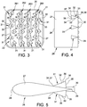
- FIG. 3 is a downstream schematic view of reheat burner 22 of the can combustor 10, i.e. reheat burner 22 is seen along axis B, counter to the hot gas flow direction.
- Channel 21 has a square/rectangular cross section and a convergent shape.
- Injection units 26 have a body 27 of substantially rectangular shape in side view ( fig. 4 ) with longer sides extending in a first direction parallel to one side of the channel 21 and orthogonal to the flow direction and shorter sides extending in the air flow direction.
- body 27 When seen along the first direction ( fig. 5 ), body 27 has a streamlined shape with a broader, rounded leading edge 28 defining one of the longer sides of body 27 and a narrower, pointed trailing edge 29 defining the other longer side of body 27.
- Injection units 26 are arranged side-by-side across channel 21 ( fig. 3 and 8 ) so as to extend substantially parallel to the first direction between opposite sides thereof, and are spaced between one another in a second direction orthogonal to the first direction. Injection units 26 are preferably slightly converging with respect to one another when seen along the first direction ( fig. 7 ), in order to follow the stream lines of the air passing through convergent channel 21.
- Each of the injection units 26 includes a plurality of fuel injection nozzles 30 configured to inject fuel in the flow direction downstream of the trailing edge 29 and extend and are spaced with one another along the first direction.
- Injection units 26 preferably comprise mixing devices configured to improve the fuel/air mixing.
- mixing devices are constituted by vortex generators 31 extending laterally from body 27, upstream of each fuel injection nozzle 30.
- Vortex generator 31 is associated to each injection nozzle 30.
- Vortex generators 31 project alternately on opposite lateral directions from body 27; according to the embodiment shown in figure 3 , vortex generators 31 associated to the first, third and fifth fuel injection nozzle 30 project on one side, while vortex generators 31 associated to the second, fourth and sixth injection nozzle (30) project on the opposite side.
- Vortex generators 31 have a substantially tetrahedral shape with one side resting against a lateral side of body 27.
- each vortex generator 31 is delimited in the first direction by two triangular side surfaces 32, 33 having respective upstream vertexes 34 at a side surface of body 27 and converge towards a common downstream base 35 that is perpendicular to the first direction and substantially perpendicular to the flow direction; each vortex generator 31 is delimited in the second direction by a triangular surface 36 having an upstream base 37 at a side surface of body 27 and a downstream vertex 38 at a free end of common downstream base 35 of side surface 32, 33.
- mixing devices can be constituted by an undulated shape of trailing edge 29 ( figure 6 ) formed by lobes 40 extending in opposed lateral directions.
- Lobes 40 can be rounded, so as to form a substantially sinusoidal profile as shown in figure 6 , or rectangular in shape, so as to form a substantially "square-wave" profile.
- Figure 8 is a schematic view of a conventional operational condition in which all injection nozzles 30 are supplied with the same fuel supply rate (uniform supply).
- the two central injection units 262, 263 mainly inject the fuel into a central, auto-ignition stabilized flame zone 40 of the combustion chamber 23, while the two external injection units 261, 264 mainly inject the fuel into a recirculation or propagation stabilized flame zone 41 of the combustion chamber 23.
- fuel supply is distributed non-uniformly among injection units 261 - 264 and/or individual injection nozzles 30 according to a predetermined pattern.
- the predetermined pattern can either be fixed, i.e. determined once for all and maintained during operation of the gas turbine, or variable.
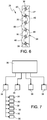
- fuel supply to injection nozzles 30 may be adjusted by valve unit 34 controlled by a programmable control unit 35 according to one or more predetermined patterns as a function of operational conditions, e.g. load ( figure 7 ).
- Valve unit may comprise one valve 36 for each of the injection units 26, in which case all of injection nozzle 30 of a given injection unit 26 receive the same fuel supply rate ( Figure 7 ), or even one valve 36 for each injection nozzle 30 (not shown), in which case fuel supply rate can be controlled individually for each point of the injection matrix.
- fuel is distributed non-uniformly between the auto-ignition stabilized flame region 40 and the propagation-stabilized flame region 41 so as to reduce thermo-acoustic pulsation.
- the distribution pattern comprises a greater fuel supply rate to the external injection units 261, 264 and a lower fuel supply rate to the central injection units 262, 263. The result is a richer air/fluid mixture in the propagation-stabilized region than in the auto-ignition region, as schematically shown in figure 9 .
- Figure 10 is a diagram where pulsation amplitude and NOx emissions are plotted against fuel rate distribution, expressed as the percentage ratio between fuel rate to outer injection units 261, 264 and the total fuel supply rate.
- Figure 11 is a scheme showing an inverted fuel distribution, where a richer mixture is created in the auto-ignition stabilized flame region. Other distributions are possible, and individual control of injection nozzles 30 may allow 2-D distribution patterns.
Landscapes
- Engineering & Computer Science (AREA)
- Chemical & Material Sciences (AREA)
- Combustion & Propulsion (AREA)
- Mechanical Engineering (AREA)
- General Engineering & Computer Science (AREA)
Abstract
Description
- This application claims priority from
US Patent Application No. 15/817,861 filed on November 20, 2017 - The present invention relates to a method of controlling fuel injection in a reheat combustor for a sequential gas turbine for power plants. In particular, the present invention relates to controlling fluid supply to reheat injection nozzles so as to minimize thermoacoustic pulsations.
- As is known, a gas turbine for power plants (in the following, "gas turbine" only) comprises an upstream compressor, a combustor assembly and a downstream turbine. The turbine includes a rotor comprising a compressor section and a turbine section.
- The terms downstream and upstream as used herein refer to the direction of the main gas flow passing through the gas turbine.
- In particular, the compressor comprises an inlet supplied with air and a plurality of blades compressing the passing air. The compressed air leaving the compressor flows into a plenum, i.e. a closed volume, and from there into the combustor, where the compressed air is mixed with at least one fuel. The mixture of fuel and compressed air flows into a combustion chamber inside the combustor where this mixture is combusted. The resulting hot gas leaves the combustor and is expanded in the turbine, producing mechanical work on the rotor.
- In order to achieve a high efficiency, a high turbine inlet temperature is required. However, due to this high temperature, high NOx emissions are generated.
- In order to reduce these emissions and to increase operational flexibility, gas turbines have been developed which comprise a combustor assembly performing a sequential combustion cycle.
- In general, a sequential combustor assembly comprises two combustors in series, wherein each combustor is provided with a respective burner and combustion chamber. Following the main gas flow direction, the upstream combustor is called "premix" combustor and is fed by the compressed air. The downstream combustor is called "sequential" or "reheat" combustor and is fed by the hot gas leaving the first combustion chamber.
- According to a first known configuration, the two combustors are physically separated by a high pressure turbine. Following the main gas flow, this first configuration includes the compressor, the premix combustor, the high-pressure turbine, the reheat combustor and a low-pressure turbine.
- According to a second known configuration, the premix and the reheat combustor are arranged directly one downstream the other inside a common casing, in particular a can-shaped casing, and no high-pressure turbine is used. According to this kind of sequential gas turbines, a plurality of can combustors are provided, which are distributed around the turbine axis.
- Each can combustor is provided with a hot gas flow channel, a reheat burner housed in the flow channel, and a reheat combustion chamber into which the flow channel opens downstream of the reheat burner. A transition duct arranged downstream the reheat combustion chamber guides the hot gas leaving the reheat combustor toward the turbine.
- The reheat burner may include a plurality of injection units in the form of substantially parallel rails or "fingers" which are arranged side-by-side and spaced with respect to one another inside the hot gas flow channel. Each of the injection units has a body extending across the gas flow channel along a first direction orthogonal to the gas flow direction, and has a streamlined shape along the gas flow direction with a leading edge and a trailing edge. Each finger bears at its trailing edge a plurality of fuel injection nozzles that are spaced between one another along the first transverse direction.
- According to a known embodiment, the injection units have integrated mixing devices configured for mixing the injected fuel with the passing hot gas flow. The mixing devices can be constituted by vortex generators in the form of triangular appendices extending from the sides of the injection units upstream from each nozzle, or by an undulated profile of the trailing edge.
- The reheat burner flame, in certain operating conditions, generates self-excited thermoacoustic pulsations which may exceed acceptable pulsation limits and undesirably restrict the gas turbine operational range. This may impair operational flexibility of the gas turbine.
- A primary object of the present invention is to provide a method for reducing flame pulsations which is cost effective and does not affect NOx emissions.
- This object is attained, according to the present invention, by a method of controlling fuel injection in a reheat combustor of a combustor assembly of a gas turbine, the reheat combustor including:
- a combustor casing defining a gas flow channel and a combustion chamber, and
- a plurality of fuel injection nozzles distributed in or around the gas flow channel;
- According to a preferred embodiment of the present invention, the non-uniform distribution pattern includes different fuel supply rates to injection nozzles injecting fuel into different flame regions in the combustion chamber. It is thus possible to influence the flame stability by enriching either the core portion of the combustion chamber, i.e. the auto-stabilized flame zone, or the outer (recirculation) portion of the combustion chamber, where the flame is propagation stabilized.
- Preferably, the reheat combustor includes a plurality of injection units, each injection unit having:
- a body extending across the gas flow channel along a first direction orthogonal to a gas flow direction and having a streamlined shape along the gas flow direction with a leading edge and a trailing edge, and
- a plurality of fuel injection nozzles spaced along the first direction.
- Preferably, the fuel supply rate to the side injection units is greater than the fuel supply rate to the at least one central injection unit. It has been found that this distribution pattern has a favourable impact on certain pulsation frequencies without affecting emissions.
- While differentiating the fuel distribution among the injection units has proven to be effective in most situation, more complex patterns including different individual fuel supply rates among the fuel nozzles in one or more of the injection units can be possible, and is encompassed in the scope of the present invention as defined by the claims.
- According to another aspect, the present invention relates to a reheat combustor of a gas turbine including a fuel injection control unit controlling the fuel supply rates to the injection nozzles and configured to selectively distribute fuel among injection nozzles according to a non-uniform distribution patter as mentioned above.
- Preferably, the injection units have integrated mixing devices configured for mixing the injected fuel with the passing hot gas flow. The mixing devices can be constituted by vortex generators in the form of shaped appendices extending from the sides of the injection units upstream from each nozzle, or by an undulated profile of the trailing edge of the injection units.
- For a better comprehension of the present invention and its advantages, an exemplary embodiment of the invention is described below in conjunction with the accompanying drawings, in which:
-
figure 1 is a schematic view of a gas turbine for power plants provided with a reheat combustor according to the present invention; -
figure 2 is a schematic view of a can combustor including a premix combustor and a reheat combustor according to the invention; -
figure 3 is a schematic downstream view of the reheat combustor of the can combustor offigure 2 ; -
figure 4 is a schematic side view of an injection unit of the reheat combustor offigure 3 ; -
figure 5 is a schematic plan view of the injection unit offigure 4 ; -
figure 6 is a schematic downstream view of an alternative embodiment of the injection unit; -
figure 7 is a block diagram of a fuel injection control system of the reheat combustor; -
figure 8 is a schematic longitudinal cross sections of the reheat combustor offig. 3 , in uniform fuel distribution conditions; -
figure 9 is a schematic longitudinal cross sections of the reheat combustor offig. 3 , in accordance with a first non-uniform distribution pattern; -
figure 10 is a diagram showing pulsation amplitude and NOx emission against fuel rate distribution; and -
figure 11 is a schematic longitudinal cross sections of the reheat combustor offig. 3 , in accordance with a second non-uniform distribution pattern. -
Figure 1 is a schematic view of a gas turbine 1 for power plants that can be provided with a reheat combustor according to the present invention. - Gas turbine 1 comprises a
compressor 2, acombustor assembly 3 and aturbine 4.Compressor 2 andturbine 4 have a common axis A and form respective sections of arotor 5 rotatable about axis A. - As is known,
ambient air 6 enterscompressor 2 and is compressed. Compressed air 7 leavescompressor 2 and enters aplenum 8, i.e. a volume defined by anouter casing 9. Fromplenum 8, compressed air 7 enterscombustor assembly 3 that comprises a plurality of can combustors 10 annularly arranged around axis A. Here at least a fuel is injected, and the air/fuel mixture is ignited, producinghot gas 11 that is conveyed toturbine 4. - As is better shown in
figure 2 , each can combustor 10 is housed in a respectiveportal hole 11 of theouter casing 9 and has an axis B. Cancombustor 10 comprises, in series along gas flow M, a first orpremix combustor 15 and a second or reheatcombustor 16. - In particular,
premix combustor 15 comprises apremix burner 17 and afirst combustion chamber 18.Reheat combustor 16 comprises ahousing 20 defining a channel 21 (better shown infigures 3 and7 ), areheat burner 22 housed within thechannel 21 and asecond combustion chamber 23. -
Reheat burner 22 comprises a plurality of, e.g. four, injection units collectively referenced 26, and individually referenced 261, 262, 263, 264.Injection units 26 are arranged acrosschannel 21 for injecting fuel into the hot gas flow. - According to a variant not illustrated the injection units can be arranged around channel for injecting fuel into the hot gas flow.
-
Figure 3 is a downstream schematic view ofreheat burner 22 of thecan combustor 10, i.e. reheatburner 22 is seen along axis B, counter to the hot gas flow direction. -
Channel 21 has a square/rectangular cross section and a convergent shape. -
Injection units 26 have abody 27 of substantially rectangular shape in side view (fig. 4 ) with longer sides extending in a first direction parallel to one side of thechannel 21 and orthogonal to the flow direction and shorter sides extending in the air flow direction. When seen along the first direction (fig. 5 ),body 27 has a streamlined shape with a broader, rounded leadingedge 28 defining one of the longer sides ofbody 27 and a narrower, pointed trailingedge 29 defining the other longer side ofbody 27. -
Injection units 26 are arranged side-by-side across channel 21 (fig. 3 and8 ) so as to extend substantially parallel to the first direction between opposite sides thereof, and are spaced between one another in a second direction orthogonal to the first direction.Injection units 26 are preferably slightly converging with respect to one another when seen along the first direction (fig. 7 ), in order to follow the stream lines of the air passing throughconvergent channel 21. - Each of the
injection units 26 includes a plurality offuel injection nozzles 30 configured to inject fuel in the flow direction downstream of the trailingedge 29 and extend and are spaced with one another along the first direction.Injection nozzles 30, in a downstream view (figure 3 ), form a rectangular matrix of injection points across a section ofchannel 21, which are spaced along the first and the second directions. -
Injection units 26 preferably comprise mixing devices configured to improve the fuel/air mixing. - According to a first embodiment (
figures 3-5 ), mixing devices are constituted byvortex generators 31 extending laterally frombody 27, upstream of eachfuel injection nozzle 30. - Preferably, a
vortex generator 31 is associated to eachinjection nozzle 30.Vortex generators 31 project alternately on opposite lateral directions frombody 27; according to the embodiment shown infigure 3 ,vortex generators 31 associated to the first, third and fifthfuel injection nozzle 30 project on one side, whilevortex generators 31 associated to the second, fourth and sixth injection nozzle (30) project on the opposite side. -
Vortex generators 31 have a substantially tetrahedral shape with one side resting against a lateral side ofbody 27. - More particularly, with reference to
figures 4 and 5 , eachvortex generator 31 is delimited in the first direction by two triangular side surfaces 32, 33 having respectiveupstream vertexes 34 at a side surface ofbody 27 and converge towards a commondownstream base 35 that is perpendicular to the first direction and substantially perpendicular to the flow direction; eachvortex generator 31 is delimited in the second direction by atriangular surface 36 having anupstream base 37 at a side surface ofbody 27 and adownstream vertex 38 at a free end of commondownstream base 35 ofside surface - As an alternative, mixing devices can be constituted by an undulated shape of trailing edge 29 (
figure 6 ) formed bylobes 40 extending in opposed lateral directions. -
Lobes 40 can be rounded, so as to form a substantially sinusoidal profile as shown infigure 6 , or rectangular in shape, so as to form a substantially "square-wave" profile. -
Figure 8 is a schematic view of a conventional operational condition in which allinjection nozzles 30 are supplied with the same fuel supply rate (uniform supply). As can be seen from the fuel streamlines schematically shown, the twocentral injection units flame zone 40 of thecombustion chamber 23, while the twoexternal injection units flame zone 41 of thecombustion chamber 23. - According to the present invention, fuel supply is distributed non-uniformly among injection units 261 - 264 and/or
individual injection nozzles 30 according to a predetermined pattern. - The predetermined pattern can either be fixed, i.e. determined once for all and maintained during operation of the gas turbine, or variable.
- In the latter case, fuel supply to
injection nozzles 30 may be adjusted byvalve unit 34 controlled by aprogrammable control unit 35 according to one or more predetermined patterns as a function of operational conditions, e.g. load (figure 7 ). - Valve unit may comprise one
valve 36 for each of theinjection units 26, in which case all ofinjection nozzle 30 of a giveninjection unit 26 receive the same fuel supply rate (Figure 7 ), or even onevalve 36 for each injection nozzle 30 (not shown), in which case fuel supply rate can be controlled individually for each point of the injection matrix. - According to one embodiment of the present invention, fuel is distributed non-uniformly between the auto-ignition stabilized
flame region 40 and the propagation-stabilizedflame region 41 so as to reduce thermo-acoustic pulsation. In particular, the distribution pattern comprises a greater fuel supply rate to theexternal injection units central injection units figure 9 . -
Figure 10 is a diagram where pulsation amplitude and NOx emissions are plotted against fuel rate distribution, expressed as the percentage ratio between fuel rate toouter injection units - As can be seen, pulsations decrease as distribution percentage increases.
-
Figure 11 is a scheme showing an inverted fuel distribution, where a richer mixture is created in the auto-ignition stabilized flame region. Other distributions are possible, and individual control ofinjection nozzles 30 may allow 2-D distribution patterns. - Although the invention has been explained in relation to its preferred embodiment(s) as mentioned above, it is to be understood that many other possible modifications and variations can be made without departing from the scope of the appended claims.
In particular, a non-uniform pattern can be selected including different fuel supply rates between two external injection units injecting fuel towards a propagation-stabilized flame region and one or more central injection unit injecting fuel towards an auto-ignition stabilized flame region of the combustion chamber.
Claims (15)
- A method of controlling fuel injection in a reheat combustor (16) of a combustor assembly (3) of a gas turbine (1), the reheat combustor (16) including:- a combustor casing (20) defining a gas flow channel (21) and a combustion chamber (23); and- a plurality of fuel injection nozzles (30) distributed in or around the gas flow channel (21)characterized by including the step of distributing fuel among the injection nozzles (30) according to a non-uniform distribution pattern.
- A method as claimed in claim 1, characterized in that said non-uniform pattern includes different fuel supply rates to injection nozzles (30) injecting fuel into different flame regions (40, 41) in the combustion chamber.
- A method as claimed in claim 1, characterized in that the reheat combustor (16) includes a plurality of injection units (26), each injection unit (26) having:- a body (27) extending across the gas flow channel (21) along a first direction orthogonal to a gas flow direction and having a streamlined shape along the gas flow direction with a leading edge (28) and a trailing edge (29), and- a plurality of fuel injection nozzles (30) spaced along the first direction;said non-uniform pattern including a different fuel supply rate to at least one of the injection units (261, 264) with respect to the other injection units (262, 263).
- A method as claimed in claim 3, characterized in that said non-uniform pattern includes different fuel supply rates between two external injection units (261, 264) injecting fuel towards a propagation-stabilized flame region (41) and at least one central injection unit (262, 263) injecting fuel towards an auto-ignition stabilized flame region (40) of the combustion chamber (23).
- A method as claimed in claim 4, characterized in that the fuel supply rate to the external injection units (261, 264) is greater than the fuel supply rate to the at least one central injection unit (262, 263).
- A method as claimed in any of the preceding claims, characterized in that said non-uniform fuel distribution pattern includes different individual fuel supply rates among the injection nozzles (30) in at least one of the injection units (26).
- A reheat combustor for a combustor assembly of a gas turbine, including:- a combustor casing (20) defining a gas flow channel (21) and a combustion chamber (23),- a plurality of fuel injection nozzles (30) distributed in or around the gas flow channel (21), and- a fuel injection control unit (35) controlling the fuel supply rates to said injection nozzles (30), characterized in that said fuel injection control unit (35) is configured to distribute fuel among the injection nozzles (30) according to a non-uniform distribution pattern.
- A reheat combustor as claimed in claim 7, characterized in that said non-uniform pattern includes different fuel supply rates to injection nozzles (30) injecting fuel into different flame regions (40, 41) in the combustion chamber (23).
- A reheat combustor as claimed in claim 7, characterized by including a plurality of side-by-side injection units (26), each injection unit having:- a body (27) extending across the gas flow channel (21) along a first direction orthogonal to the gas flow direction and having a streamlined shape along the gas flow direction with a leading edge (28) and a trailing edge (29), and- a plurality of fuel injection nozzles (30) spaced along the first direction,said non-uniform pattern including a different fuel supply rate to at least one of the injection units (261, 264) with respect to the other injection units (262, 263).
- A reheat combustor as claimed in claim 9, characterized in that said non-uniform pattern includes different fuel supply rates between two external injection units (261, 264) injecting fuel towards a propagation-stabilized flame region (41) and at least one central injection unit (262, 263) injecting fuel towards an auto-ignition stabilized flame region (40) of the combustion chamber (23).
- A reheat combustor as claimed in claim 9, characterized in that the fuel supply rate to the external injection units (261, 264) is greater than the fuel supply rate to the at least one central injection unit (262, 263).
- A reheat combustor as claimed in any of claims 7 to 11, characterized in that said non-uniform fuel distribution pattern includes different individual fuel supply rates among the injection nozzles (30) in at least one of the injection units (26).
- A reheat combustor as claimed in any of claims 7 to 12, characterized in that said injection units (26) include integrated mixing devices (31, 40) configured for mixing the injected fuel with passing hot gas flow.
- A reheat combustor as claimed in claim 13, characterized in that the mixing devices are constituted by vortex generators (31) in the form of lateral appendices extending from the sides of the injection units (26) upstream from each injection nozzle (30).
- A reheat combustor as claimed in claim 13, characterized in that the mixing devices are constituted by lobes (40) of the trailing edge (29) of each injection unit (26) forming an undulated profile thereof.
Applications Claiming Priority (1)
| Application Number | Priority Date | Filing Date | Title |
|---|---|---|---|
| US15/817,861 US11242806B2 (en) | 2017-11-20 | 2017-11-20 | Method of controlling fuel injection in a reheat combustor for a combustor unit of a gas turbine |
Publications (3)
| Publication Number | Publication Date |
|---|---|
| EP3486568A1 true EP3486568A1 (en) | 2019-05-22 |
| EP3486568A8 EP3486568A8 (en) | 2019-07-31 |
| EP3486568B1 EP3486568B1 (en) | 2020-09-09 |
Family
ID=64426686
Family Applications (1)
| Application Number | Title | Priority Date | Filing Date |
|---|---|---|---|
| EP18207407.0A Active EP3486568B1 (en) | 2017-11-20 | 2018-11-20 | Method of controlling fuel injection in a reheat combustor for a cambustor assembly of a gas turbine and associated reheat combustor |
Country Status (3)
| Country | Link |
|---|---|
| US (1) | US11242806B2 (en) |
| EP (1) | EP3486568B1 (en) |
| CN (1) | CN110030580B (en) |
Cited By (1)
| Publication number | Priority date | Publication date | Assignee | Title |
|---|---|---|---|---|
| EP4019840A1 (en) * | 2020-12-24 | 2022-06-29 | Ansaldo Energia Switzerland AG | Combustor unit for a gas turbine assembly, gas turbine assembly and method for controlling fuel injection in a combustor unit for a gas turbine assembly |
Families Citing this family (3)
| Publication number | Priority date | Publication date | Assignee | Title |
|---|---|---|---|---|
| US11454396B1 (en) * | 2021-06-07 | 2022-09-27 | General Electric Company | Fuel injector and pre-mixer system for a burner array |
| CN113460299B (en) * | 2021-09-02 | 2021-11-30 | 中国空气动力研究与发展中心低速空气动力研究所 | Jet structure for reducing drag of coaxial rigid rotor hub and using method thereof |
| US20230408094A1 (en) * | 2021-11-03 | 2023-12-21 | Power Systems Mfg., Llc | Trailing edge fuel injection enhancement for flame holding mitigation |
Citations (3)
| Publication number | Priority date | Publication date | Assignee | Title |
|---|---|---|---|---|
| US20100170219A1 (en) * | 2009-01-07 | 2010-07-08 | General Electric Company | Late lean injection control strategy |
| EP2725301A1 (en) * | 2012-10-23 | 2014-04-30 | Alstom Technology Ltd | Burner for a can combustor |
| EP3184748A1 (en) * | 2015-12-22 | 2017-06-28 | General Electric Company | Staged fuel and air injection in combustion systems of gas turbines |
Family Cites Families (16)
| Publication number | Priority date | Publication date | Assignee | Title |
|---|---|---|---|---|
| US5836164A (en) * | 1995-01-30 | 1998-11-17 | Hitachi, Ltd. | Gas turbine combustor |
| WO2011054739A2 (en) * | 2009-11-07 | 2011-05-12 | Alstom Technology Ltd | Reheat burner injection system |
| WO2011054771A2 (en) * | 2009-11-07 | 2011-05-12 | Alstom Technology Ltd | Premixed burner for a gas turbine combustor |
| GB0920094D0 (en) * | 2009-11-17 | 2009-12-30 | Alstom Technology Ltd | Reheat combustor for a gas turbine engine |
| RU2550370C2 (en) * | 2011-05-11 | 2015-05-10 | Альстом Текнолоджи Лтд | Centrifugal nozzle with projecting parts |
| US8938971B2 (en) * | 2011-05-11 | 2015-01-27 | Alstom Technology Ltd | Flow straightener and mixer |
| EP2725302A1 (en) * | 2012-10-25 | 2014-04-30 | Alstom Technology Ltd | Reheat burner arrangement |
| EP2837883B1 (en) * | 2013-08-16 | 2018-04-04 | Ansaldo Energia Switzerland AG | Premixed can annular combustor with mixing lobes for the second stage of a sequential gas turbine |
| EP3015772B1 (en) * | 2014-10-31 | 2020-01-08 | Ansaldo Energia Switzerland AG | Combustor arrangement for a gas turbine |
| EP3023696B1 (en) * | 2014-11-20 | 2019-08-28 | Ansaldo Energia Switzerland AG | Lobe lance for a gas turbine combustor |
| EP3026344B1 (en) * | 2014-11-26 | 2019-05-22 | Ansaldo Energia Switzerland AG | Burner of a gas turbine |
| EP3056819B1 (en) * | 2015-02-11 | 2020-04-01 | Ansaldo Energia Switzerland AG | Fuel injection device for a gas turbine |
| EP3073198B1 (en) * | 2015-03-27 | 2019-12-25 | Ansaldo Energia Switzerland AG | Integrated dual fuel delivery system |
| EP3147569A1 (en) * | 2015-09-28 | 2017-03-29 | General Electric Technology GmbH | Vortex generator, and fuel injection system of a gas turbine with such vortex generator |
| US20170268785A1 (en) * | 2016-03-15 | 2017-09-21 | General Electric Company | Staged fuel and air injectors in combustion systems of gas turbines |
| EP3306197B1 (en) * | 2016-10-08 | 2020-01-29 | Ansaldo Energia Switzerland AG | Dual fuel injector for a sequential burner of a sequential gas turbine |
-
2017
- 2017-11-20 US US15/817,861 patent/US11242806B2/en active Active
-
2018
- 2018-11-20 CN CN201811384464.1A patent/CN110030580B/en not_active Expired - Fee Related
- 2018-11-20 EP EP18207407.0A patent/EP3486568B1/en active Active
Patent Citations (3)
| Publication number | Priority date | Publication date | Assignee | Title |
|---|---|---|---|---|
| US20100170219A1 (en) * | 2009-01-07 | 2010-07-08 | General Electric Company | Late lean injection control strategy |
| EP2725301A1 (en) * | 2012-10-23 | 2014-04-30 | Alstom Technology Ltd | Burner for a can combustor |
| EP3184748A1 (en) * | 2015-12-22 | 2017-06-28 | General Electric Company | Staged fuel and air injection in combustion systems of gas turbines |
Cited By (1)
| Publication number | Priority date | Publication date | Assignee | Title |
|---|---|---|---|---|
| EP4019840A1 (en) * | 2020-12-24 | 2022-06-29 | Ansaldo Energia Switzerland AG | Combustor unit for a gas turbine assembly, gas turbine assembly and method for controlling fuel injection in a combustor unit for a gas turbine assembly |
Also Published As
| Publication number | Publication date |
|---|---|
| EP3486568A8 (en) | 2019-07-31 |
| CN110030580A (en) | 2019-07-19 |
| CN110030580B (en) | 2022-07-26 |
| US11242806B2 (en) | 2022-02-08 |
| US20190154263A1 (en) | 2019-05-23 |
| EP3486568B1 (en) | 2020-09-09 |
Similar Documents
| Publication | Publication Date | Title |
|---|---|---|
| EP3486568B1 (en) | Method of controlling fuel injection in a reheat combustor for a cambustor assembly of a gas turbine and associated reheat combustor | |
| CN105627368B (en) | Lobed nozzle for gas turbine combustor | |
| US10054313B2 (en) | Air biasing system in a gas turbine combustor | |
| US8769955B2 (en) | Self-regulating fuel staging port for turbine combustor | |
| US8117846B2 (en) | Gas turbine burner and method of mixing fuel and air in a swirling area of a gas turbine burner | |
| EP1426689B1 (en) | Gas turbine combustor having staged burners with dissimilar mixing passage geometries | |
| US20050034457A1 (en) | Fuel injection system for a turbine engine | |
| CN110195655B (en) | Engine with rotary detonation combustion system | |
| CN101636619B (en) | Fuel-air premixing arrangement structure ,burner and method for operating the burner | |
| JPH08135970A (en) | Gas turbine combustor | |
| EP3069081A1 (en) | Fuel injection system for a turbine engine | |
| US6220035B1 (en) | Annular combustor tangential injection flame stabilizer | |
| US8726671B2 (en) | Operation of a combustor apparatus in a gas turbine engine | |
| US20170198913A1 (en) | Fuel injection system for a turbine engine | |
| US10371048B2 (en) | Combustor and gas turbine | |
| US20140033719A1 (en) | Multi-step combustor | |
| CN115597089B (en) | Cyclone assembly, multi-point staged lean direct injection combustor and control method thereof | |
| EP4019840B1 (en) | Combustor unit for a gas turbine assembly | |
| KR20180089299A (en) | Device to correct flow non-uniformity within a combustion system | |
| KR102153456B1 (en) | Combustor for a gas turbine | |
| KR102062527B1 (en) | Burner Having Fuel Injection Peg, And Gas Turbine Having The Same | |
| CN111623373B (en) | Sequential combustor for a gas turbine, method for operating the same and method for refurbishing the same | |
| WO2017196356A1 (en) | A method of selective combustor control for reduced emissions | |
| CN114251674A (en) | Fuel injection head, combustion chamber, gas turbine engine, and combustion control method | |
| CN111623372A (en) | Method of operating a sequential combustor and gas turbine comprising a sequential combustor |
Legal Events
| Date | Code | Title | Description |
|---|---|---|---|
| PUAI | Public reference made under article 153(3) epc to a published international application that has entered the european phase |
Free format text: ORIGINAL CODE: 0009012 |
|
| STAA | Information on the status of an ep patent application or granted ep patent |
Free format text: STATUS: THE APPLICATION HAS BEEN PUBLISHED |
|
| AK | Designated contracting states |
Kind code of ref document: A1 Designated state(s): AL AT BE BG CH CY CZ DE DK EE ES FI FR GB GR HR HU IE IS IT LI LT LU LV MC MK MT NL NO PL PT RO RS SE SI SK SM TR |
|
| AX | Request for extension of the european patent |
Extension state: BA ME |
|
| STAA | Information on the status of an ep patent application or granted ep patent |
Free format text: STATUS: REQUEST FOR EXAMINATION WAS MADE |
|
| 17P | Request for examination filed |
Effective date: 20191121 |
|
| RBV | Designated contracting states (corrected) |
Designated state(s): AL AT BE BG CH CY CZ DE DK EE ES FI FR GB GR HR HU IE IS IT LI LT LU LV MC MK MT NL NO PL PT RO RS SE SI SK SM TR |
|
| GRAP | Despatch of communication of intention to grant a patent |
Free format text: ORIGINAL CODE: EPIDOSNIGR1 |
|
| STAA | Information on the status of an ep patent application or granted ep patent |
Free format text: STATUS: GRANT OF PATENT IS INTENDED |
|
| INTG | Intention to grant announced |
Effective date: 20200403 |
|
| GRAS | Grant fee paid |
Free format text: ORIGINAL CODE: EPIDOSNIGR3 |
|
| GRAA | (expected) grant |
Free format text: ORIGINAL CODE: 0009210 |
|
| STAA | Information on the status of an ep patent application or granted ep patent |
Free format text: STATUS: THE PATENT HAS BEEN GRANTED |
|
| AK | Designated contracting states |
Kind code of ref document: B1 Designated state(s): AL AT BE BG CH CY CZ DE DK EE ES FI FR GB GR HR HU IE IS IT LI LT LU LV MC MK MT NL NO PL PT RO RS SE SI SK SM TR |
|
| REG | Reference to a national code |
Ref country code: GB Ref legal event code: FG4D |
|
| REG | Reference to a national code |
Ref country code: AT Ref legal event code: REF Ref document number: 1312031 Country of ref document: AT Kind code of ref document: T Effective date: 20200915 Ref country code: CH Ref legal event code: EP |
|
| REG | Reference to a national code |
Ref country code: IE Ref legal event code: FG4D |
|
| REG | Reference to a national code |
Ref country code: DE Ref legal event code: R096 Ref document number: 602018007623 Country of ref document: DE |
|
| REG | Reference to a national code |
Ref country code: LT Ref legal event code: MG4D |
|
| PG25 | Lapsed in a contracting state [announced via postgrant information from national office to epo] |
Ref country code: NO Free format text: LAPSE BECAUSE OF FAILURE TO SUBMIT A TRANSLATION OF THE DESCRIPTION OR TO PAY THE FEE WITHIN THE PRESCRIBED TIME-LIMIT Effective date: 20201209 Ref country code: HR Free format text: LAPSE BECAUSE OF FAILURE TO SUBMIT A TRANSLATION OF THE DESCRIPTION OR TO PAY THE FEE WITHIN THE PRESCRIBED TIME-LIMIT Effective date: 20200909 Ref country code: LT Free format text: LAPSE BECAUSE OF FAILURE TO SUBMIT A TRANSLATION OF THE DESCRIPTION OR TO PAY THE FEE WITHIN THE PRESCRIBED TIME-LIMIT Effective date: 20200909 Ref country code: BG Free format text: LAPSE BECAUSE OF FAILURE TO SUBMIT A TRANSLATION OF THE DESCRIPTION OR TO PAY THE FEE WITHIN THE PRESCRIBED TIME-LIMIT Effective date: 20201209 Ref country code: GR Free format text: LAPSE BECAUSE OF FAILURE TO SUBMIT A TRANSLATION OF THE DESCRIPTION OR TO PAY THE FEE WITHIN THE PRESCRIBED TIME-LIMIT Effective date: 20201210 Ref country code: FI Free format text: LAPSE BECAUSE OF FAILURE TO SUBMIT A TRANSLATION OF THE DESCRIPTION OR TO PAY THE FEE WITHIN THE PRESCRIBED TIME-LIMIT Effective date: 20200909 Ref country code: SE Free format text: LAPSE BECAUSE OF FAILURE TO SUBMIT A TRANSLATION OF THE DESCRIPTION OR TO PAY THE FEE WITHIN THE PRESCRIBED TIME-LIMIT Effective date: 20200909 |
|
| REG | Reference to a national code |
Ref country code: AT Ref legal event code: MK05 Ref document number: 1312031 Country of ref document: AT Kind code of ref document: T Effective date: 20200909 |
|
| REG | Reference to a national code |
Ref country code: NL Ref legal event code: MP Effective date: 20200909 |
|
| PG25 | Lapsed in a contracting state [announced via postgrant information from national office to epo] |
Ref country code: LV Free format text: LAPSE BECAUSE OF FAILURE TO SUBMIT A TRANSLATION OF THE DESCRIPTION OR TO PAY THE FEE WITHIN THE PRESCRIBED TIME-LIMIT Effective date: 20200909 Ref country code: RS Free format text: LAPSE BECAUSE OF FAILURE TO SUBMIT A TRANSLATION OF THE DESCRIPTION OR TO PAY THE FEE WITHIN THE PRESCRIBED TIME-LIMIT Effective date: 20200909 Ref country code: PL Free format text: LAPSE BECAUSE OF FAILURE TO SUBMIT A TRANSLATION OF THE DESCRIPTION OR TO PAY THE FEE WITHIN THE PRESCRIBED TIME-LIMIT Effective date: 20200909 |
|
| PG25 | Lapsed in a contracting state [announced via postgrant information from national office to epo] |
Ref country code: EE Free format text: LAPSE BECAUSE OF FAILURE TO SUBMIT A TRANSLATION OF THE DESCRIPTION OR TO PAY THE FEE WITHIN THE PRESCRIBED TIME-LIMIT Effective date: 20200909 Ref country code: CZ Free format text: LAPSE BECAUSE OF FAILURE TO SUBMIT A TRANSLATION OF THE DESCRIPTION OR TO PAY THE FEE WITHIN THE PRESCRIBED TIME-LIMIT Effective date: 20200909 Ref country code: PT Free format text: LAPSE BECAUSE OF FAILURE TO SUBMIT A TRANSLATION OF THE DESCRIPTION OR TO PAY THE FEE WITHIN THE PRESCRIBED TIME-LIMIT Effective date: 20210111 Ref country code: RO Free format text: LAPSE BECAUSE OF FAILURE TO SUBMIT A TRANSLATION OF THE DESCRIPTION OR TO PAY THE FEE WITHIN THE PRESCRIBED TIME-LIMIT Effective date: 20200909 Ref country code: SM Free format text: LAPSE BECAUSE OF FAILURE TO SUBMIT A TRANSLATION OF THE DESCRIPTION OR TO PAY THE FEE WITHIN THE PRESCRIBED TIME-LIMIT Effective date: 20200909 |
|
| PG25 | Lapsed in a contracting state [announced via postgrant information from national office to epo] |
Ref country code: IS Free format text: LAPSE BECAUSE OF FAILURE TO SUBMIT A TRANSLATION OF THE DESCRIPTION OR TO PAY THE FEE WITHIN THE PRESCRIBED TIME-LIMIT Effective date: 20210109 Ref country code: ES Free format text: LAPSE BECAUSE OF FAILURE TO SUBMIT A TRANSLATION OF THE DESCRIPTION OR TO PAY THE FEE WITHIN THE PRESCRIBED TIME-LIMIT Effective date: 20200909 Ref country code: AT Free format text: LAPSE BECAUSE OF FAILURE TO SUBMIT A TRANSLATION OF THE DESCRIPTION OR TO PAY THE FEE WITHIN THE PRESCRIBED TIME-LIMIT Effective date: 20200909 Ref country code: AL Free format text: LAPSE BECAUSE OF FAILURE TO SUBMIT A TRANSLATION OF THE DESCRIPTION OR TO PAY THE FEE WITHIN THE PRESCRIBED TIME-LIMIT Effective date: 20200909 |
|
| REG | Reference to a national code |
Ref country code: DE Ref legal event code: R097 Ref document number: 602018007623 Country of ref document: DE |
|
| PG25 | Lapsed in a contracting state [announced via postgrant information from national office to epo] |
Ref country code: MC Free format text: LAPSE BECAUSE OF FAILURE TO SUBMIT A TRANSLATION OF THE DESCRIPTION OR TO PAY THE FEE WITHIN THE PRESCRIBED TIME-LIMIT Effective date: 20200909 Ref country code: SK Free format text: LAPSE BECAUSE OF FAILURE TO SUBMIT A TRANSLATION OF THE DESCRIPTION OR TO PAY THE FEE WITHIN THE PRESCRIBED TIME-LIMIT Effective date: 20200909 |
|
| PLBE | No opposition filed within time limit |
Free format text: ORIGINAL CODE: 0009261 |
|
| STAA | Information on the status of an ep patent application or granted ep patent |
Free format text: STATUS: NO OPPOSITION FILED WITHIN TIME LIMIT |
|
| PG25 | Lapsed in a contracting state [announced via postgrant information from national office to epo] |
Ref country code: LU Free format text: LAPSE BECAUSE OF NON-PAYMENT OF DUE FEES Effective date: 20201120 |
|
| REG | Reference to a national code |
Ref country code: BE Ref legal event code: MM Effective date: 20201130 |
|
| 26N | No opposition filed |
Effective date: 20210610 |
|
| PG25 | Lapsed in a contracting state [announced via postgrant information from national office to epo] |
Ref country code: DK Free format text: LAPSE BECAUSE OF FAILURE TO SUBMIT A TRANSLATION OF THE DESCRIPTION OR TO PAY THE FEE WITHIN THE PRESCRIBED TIME-LIMIT Effective date: 20200909 Ref country code: SI Free format text: LAPSE BECAUSE OF FAILURE TO SUBMIT A TRANSLATION OF THE DESCRIPTION OR TO PAY THE FEE WITHIN THE PRESCRIBED TIME-LIMIT Effective date: 20200909 |
|
| PG25 | Lapsed in a contracting state [announced via postgrant information from national office to epo] |
Ref country code: IT Free format text: LAPSE BECAUSE OF FAILURE TO SUBMIT A TRANSLATION OF THE DESCRIPTION OR TO PAY THE FEE WITHIN THE PRESCRIBED TIME-LIMIT Effective date: 20200909 Ref country code: IE Free format text: LAPSE BECAUSE OF NON-PAYMENT OF DUE FEES Effective date: 20201120 Ref country code: FR Free format text: LAPSE BECAUSE OF NON-PAYMENT OF DUE FEES Effective date: 20201130 |
|
| PG25 | Lapsed in a contracting state [announced via postgrant information from national office to epo] |
Ref country code: TR Free format text: LAPSE BECAUSE OF FAILURE TO SUBMIT A TRANSLATION OF THE DESCRIPTION OR TO PAY THE FEE WITHIN THE PRESCRIBED TIME-LIMIT Effective date: 20200909 Ref country code: MT Free format text: LAPSE BECAUSE OF FAILURE TO SUBMIT A TRANSLATION OF THE DESCRIPTION OR TO PAY THE FEE WITHIN THE PRESCRIBED TIME-LIMIT Effective date: 20200909 Ref country code: CY Free format text: LAPSE BECAUSE OF FAILURE TO SUBMIT A TRANSLATION OF THE DESCRIPTION OR TO PAY THE FEE WITHIN THE PRESCRIBED TIME-LIMIT Effective date: 20200909 |
|
| PG25 | Lapsed in a contracting state [announced via postgrant information from national office to epo] |
Ref country code: MK Free format text: LAPSE BECAUSE OF FAILURE TO SUBMIT A TRANSLATION OF THE DESCRIPTION OR TO PAY THE FEE WITHIN THE PRESCRIBED TIME-LIMIT Effective date: 20200909 |
|
| REG | Reference to a national code |
Ref country code: CH Ref legal event code: PL |
|
| PG25 | Lapsed in a contracting state [announced via postgrant information from national office to epo] |
Ref country code: BE Free format text: LAPSE BECAUSE OF NON-PAYMENT OF DUE FEES Effective date: 20201130 |
|
| PG25 | Lapsed in a contracting state [announced via postgrant information from national office to epo] |
Ref country code: NL Free format text: LAPSE BECAUSE OF NON-PAYMENT OF DUE FEES Effective date: 20200923 |
|
| GBPC | Gb: european patent ceased through non-payment of renewal fee |
Effective date: 20221120 |
|
| PG25 | Lapsed in a contracting state [announced via postgrant information from national office to epo] |
Ref country code: LI Free format text: LAPSE BECAUSE OF NON-PAYMENT OF DUE FEES Effective date: 20220630 Ref country code: CH Free format text: LAPSE BECAUSE OF NON-PAYMENT OF DUE FEES Effective date: 20220630 |
|
| PG25 | Lapsed in a contracting state [announced via postgrant information from national office to epo] |
Ref country code: GB Free format text: LAPSE BECAUSE OF NON-PAYMENT OF DUE FEES Effective date: 20221120 |
|
| PGFP | Annual fee paid to national office [announced via postgrant information from national office to epo] |
Ref country code: DE Payment date: 20230926 Year of fee payment: 6 |