EP3486487A1 - Compressor having muffler function - Google Patents
Compressor having muffler function Download PDFInfo
- Publication number
- EP3486487A1 EP3486487A1 EP17827746.3A EP17827746A EP3486487A1 EP 3486487 A1 EP3486487 A1 EP 3486487A1 EP 17827746 A EP17827746 A EP 17827746A EP 3486487 A1 EP3486487 A1 EP 3486487A1
- Authority
- EP
- European Patent Office
- Prior art keywords
- flow path
- throttle portion
- refrigerant
- compressor according
- sectional area
- Prior art date
- Legal status (The legal status is an assumption and is not a legal conclusion. Google has not performed a legal analysis and makes no representation as to the accuracy of the status listed.)
- Granted
Links
Images






Classifications
-
- F—MECHANICAL ENGINEERING; LIGHTING; HEATING; WEAPONS; BLASTING
- F04—POSITIVE - DISPLACEMENT MACHINES FOR LIQUIDS; PUMPS FOR LIQUIDS OR ELASTIC FLUIDS
- F04C—ROTARY-PISTON, OR OSCILLATING-PISTON, POSITIVE-DISPLACEMENT MACHINES FOR LIQUIDS; ROTARY-PISTON, OR OSCILLATING-PISTON, POSITIVE-DISPLACEMENT PUMPS
- F04C29/00—Component parts, details or accessories of pumps or pumping installations, not provided for in groups F04C18/00 - F04C28/00
- F04C29/06—Silencing
- F04C29/065—Noise dampening volumes, e.g. muffler chambers
-
- F—MECHANICAL ENGINEERING; LIGHTING; HEATING; WEAPONS; BLASTING
- F04—POSITIVE - DISPLACEMENT MACHINES FOR LIQUIDS; PUMPS FOR LIQUIDS OR ELASTIC FLUIDS
- F04B—POSITIVE-DISPLACEMENT MACHINES FOR LIQUIDS; PUMPS
- F04B39/00—Component parts, details, or accessories, of pumps or pumping systems specially adapted for elastic fluids, not otherwise provided for in, or of interest apart from, groups F04B25/00 - F04B37/00
- F04B39/12—Casings; Cylinders; Cylinder heads; Fluid connections
-
- F—MECHANICAL ENGINEERING; LIGHTING; HEATING; WEAPONS; BLASTING
- F04—POSITIVE - DISPLACEMENT MACHINES FOR LIQUIDS; PUMPS FOR LIQUIDS OR ELASTIC FLUIDS
- F04B—POSITIVE-DISPLACEMENT MACHINES FOR LIQUIDS; PUMPS
- F04B39/00—Component parts, details, or accessories, of pumps or pumping systems specially adapted for elastic fluids, not otherwise provided for in, or of interest apart from, groups F04B25/00 - F04B37/00
-
- F—MECHANICAL ENGINEERING; LIGHTING; HEATING; WEAPONS; BLASTING
- F04—POSITIVE - DISPLACEMENT MACHINES FOR LIQUIDS; PUMPS FOR LIQUIDS OR ELASTIC FLUIDS
- F04B—POSITIVE-DISPLACEMENT MACHINES FOR LIQUIDS; PUMPS
- F04B39/00—Component parts, details, or accessories, of pumps or pumping systems specially adapted for elastic fluids, not otherwise provided for in, or of interest apart from, groups F04B25/00 - F04B37/00
- F04B39/0027—Pulsation and noise damping means
- F04B39/0055—Pulsation and noise damping means with a special shape of fluid passage, e.g. bends, throttles, diameter changes, pipes
-
- F—MECHANICAL ENGINEERING; LIGHTING; HEATING; WEAPONS; BLASTING
- F04—POSITIVE - DISPLACEMENT MACHINES FOR LIQUIDS; PUMPS FOR LIQUIDS OR ELASTIC FLUIDS
- F04B—POSITIVE-DISPLACEMENT MACHINES FOR LIQUIDS; PUMPS
- F04B39/00—Component parts, details, or accessories, of pumps or pumping systems specially adapted for elastic fluids, not otherwise provided for in, or of interest apart from, groups F04B25/00 - F04B37/00
- F04B39/0027—Pulsation and noise damping means
- F04B39/0055—Pulsation and noise damping means with a special shape of fluid passage, e.g. bends, throttles, diameter changes, pipes
- F04B39/0061—Pulsation and noise damping means with a special shape of fluid passage, e.g. bends, throttles, diameter changes, pipes using muffler volumes
-
- F—MECHANICAL ENGINEERING; LIGHTING; HEATING; WEAPONS; BLASTING
- F04—POSITIVE - DISPLACEMENT MACHINES FOR LIQUIDS; PUMPS FOR LIQUIDS OR ELASTIC FLUIDS
- F04B—POSITIVE-DISPLACEMENT MACHINES FOR LIQUIDS; PUMPS
- F04B39/00—Component parts, details, or accessories, of pumps or pumping systems specially adapted for elastic fluids, not otherwise provided for in, or of interest apart from, groups F04B25/00 - F04B37/00
- F04B39/06—Cooling; Heating; Prevention of freezing
-
- F—MECHANICAL ENGINEERING; LIGHTING; HEATING; WEAPONS; BLASTING
- F04—POSITIVE - DISPLACEMENT MACHINES FOR LIQUIDS; PUMPS FOR LIQUIDS OR ELASTIC FLUIDS
- F04B—POSITIVE-DISPLACEMENT MACHINES FOR LIQUIDS; PUMPS
- F04B39/00—Component parts, details, or accessories, of pumps or pumping systems specially adapted for elastic fluids, not otherwise provided for in, or of interest apart from, groups F04B25/00 - F04B37/00
- F04B39/12—Casings; Cylinders; Cylinder heads; Fluid connections
- F04B39/123—Fluid connections
-
- F—MECHANICAL ENGINEERING; LIGHTING; HEATING; WEAPONS; BLASTING
- F04—POSITIVE - DISPLACEMENT MACHINES FOR LIQUIDS; PUMPS FOR LIQUIDS OR ELASTIC FLUIDS
- F04C—ROTARY-PISTON, OR OSCILLATING-PISTON, POSITIVE-DISPLACEMENT MACHINES FOR LIQUIDS; ROTARY-PISTON, OR OSCILLATING-PISTON, POSITIVE-DISPLACEMENT PUMPS
- F04C18/00—Rotary-piston pumps specially adapted for elastic fluids
- F04C18/02—Rotary-piston pumps specially adapted for elastic fluids of arcuate-engagement type, i.e. with circular translatory movement of co-operating members, each member having the same number of teeth or tooth-equivalents
- F04C18/0207—Rotary-piston pumps specially adapted for elastic fluids of arcuate-engagement type, i.e. with circular translatory movement of co-operating members, each member having the same number of teeth or tooth-equivalents both members having co-operating elements in spiral form
- F04C18/0215—Rotary-piston pumps specially adapted for elastic fluids of arcuate-engagement type, i.e. with circular translatory movement of co-operating members, each member having the same number of teeth or tooth-equivalents both members having co-operating elements in spiral form where only one member is moving
-
- F—MECHANICAL ENGINEERING; LIGHTING; HEATING; WEAPONS; BLASTING
- F04—POSITIVE - DISPLACEMENT MACHINES FOR LIQUIDS; PUMPS FOR LIQUIDS OR ELASTIC FLUIDS
- F04C—ROTARY-PISTON, OR OSCILLATING-PISTON, POSITIVE-DISPLACEMENT MACHINES FOR LIQUIDS; ROTARY-PISTON, OR OSCILLATING-PISTON, POSITIVE-DISPLACEMENT PUMPS
- F04C29/00—Component parts, details or accessories of pumps or pumping installations, not provided for in groups F04C18/00 - F04C28/00
- F04C29/04—Heating; Cooling; Heat insulation
-
- F—MECHANICAL ENGINEERING; LIGHTING; HEATING; WEAPONS; BLASTING
- F04—POSITIVE - DISPLACEMENT MACHINES FOR LIQUIDS; PUMPS FOR LIQUIDS OR ELASTIC FLUIDS
- F04C—ROTARY-PISTON, OR OSCILLATING-PISTON, POSITIVE-DISPLACEMENT MACHINES FOR LIQUIDS; ROTARY-PISTON, OR OSCILLATING-PISTON, POSITIVE-DISPLACEMENT PUMPS
- F04C29/00—Component parts, details or accessories of pumps or pumping installations, not provided for in groups F04C18/00 - F04C28/00
- F04C29/06—Silencing
-
- F—MECHANICAL ENGINEERING; LIGHTING; HEATING; WEAPONS; BLASTING
- F04—POSITIVE - DISPLACEMENT MACHINES FOR LIQUIDS; PUMPS FOR LIQUIDS OR ELASTIC FLUIDS
- F04C—ROTARY-PISTON, OR OSCILLATING-PISTON, POSITIVE-DISPLACEMENT MACHINES FOR LIQUIDS; ROTARY-PISTON, OR OSCILLATING-PISTON, POSITIVE-DISPLACEMENT PUMPS
- F04C29/00—Component parts, details or accessories of pumps or pumping installations, not provided for in groups F04C18/00 - F04C28/00
- F04C29/12—Arrangements for admission or discharge of the working fluid, e.g. constructional features of the inlet or outlet
-
- F—MECHANICAL ENGINEERING; LIGHTING; HEATING; WEAPONS; BLASTING
- F04—POSITIVE - DISPLACEMENT MACHINES FOR LIQUIDS; PUMPS FOR LIQUIDS OR ELASTIC FLUIDS
- F04C—ROTARY-PISTON, OR OSCILLATING-PISTON, POSITIVE-DISPLACEMENT MACHINES FOR LIQUIDS; ROTARY-PISTON, OR OSCILLATING-PISTON, POSITIVE-DISPLACEMENT PUMPS
- F04C2210/00—Fluid
- F04C2210/22—Fluid gaseous, i.e. compressible
-
- F—MECHANICAL ENGINEERING; LIGHTING; HEATING; WEAPONS; BLASTING
- F04—POSITIVE - DISPLACEMENT MACHINES FOR LIQUIDS; PUMPS FOR LIQUIDS OR ELASTIC FLUIDS
- F04C—ROTARY-PISTON, OR OSCILLATING-PISTON, POSITIVE-DISPLACEMENT MACHINES FOR LIQUIDS; ROTARY-PISTON, OR OSCILLATING-PISTON, POSITIVE-DISPLACEMENT PUMPS
- F04C2270/00—Control; Monitoring or safety arrangements
- F04C2270/13—Noise
- F04C2270/135—Controlled or regulated
Definitions
- the present invention relates to a compressor.
- a compressor is used in a refrigerant circuit such as an air conditioner.
- the compressor sucks a low-pressure gas refrigerant into its compression chamber and compresses the low-pressure gas refrigerant to produce a high-pressure gas refrigerant to discharge.
- Some compressors implement a technique called gas injection in order to improve the capacity of the refrigerant circuit.
- a pipe called an injection pipe is connected to the compression chamber of the compressor.
- an intermediate pressure gas refrigerant that indicates a pressure value between the low-pressure gas refrigerant and the high-pressure gas refrigerant.
- the injection pipe introduces the intermediate gas refrigerant into the compression chamber.
- Patent Document 1 Japanese Laid-Open Patent Application Publication No. 2010-185406 discloses an air conditioner in which a muffler is attached to the injection pipe.
- piping such as the injection pipe connecting the compressor and the muffler receives a large stress, which may cause a problem in terms of reliability of the equipment.
- the present invention has been made to accomplish an objective of decreasing defects caused by vibrations and stress that a pipe receives in a compressor.
- a compressor compresses a low-pressure refrigerant sucked therein to discharge a high-pressure refrigerant.
- the compressor includes a first throttle portion, an enlarged flow path portion, a second throttle portion, and a compression element.
- the first throttle portion receives a refrigerant at an intermediate pressure from an injection pipe of a refrigerant circuit.
- the enlarged flow path portion receives the refrigerant from the first throttle portion.
- the second throttle portion receives the refrigerant from the enlarged flow path portion.
- the compression element has a compression chamber that receives the refrigerant from the second throttle portion.
- the first throttle portion has a flow path cross-sectional area that is narrower than both a flow path cross-sectional area of the injection pipe and a flow path cross-sectional area of the enlarged flow path portion.
- the second throttle portion has a flow path cross-sectional area that is narrower than the flow path cross-sectional area of the enlarged flow path portion.
- the first throttle portion, the enlarged flow path portion, and the second throttle portion have different flow path cross-sectional areas. Therefore, the path composed of the first throttle portion, the enlarged flow path portion, and the second throttle portion functions as a muffler and reduces the vibrations of each portion caused by pressure pulsation of the refrigerant.
- a compressor according to a second aspect of the present invention is the compressor according to the first aspect of the present invention further including a pressure vessel that accommodates the compression element. At least a part of the second throttle portion is provided in the pressure vessel.
- At least a part of the second throttle portion is provided in the pressure vessel. Since a part of the flow of the pulsating refrigerant passes through the pressure vessel, the noise outside the pressure vessel is reduced as a result.
- a compressor according to a third aspect of the present invention is the compressor according to the second aspect of the present invention, wherein at least a part of the enlarged flow path portion is provided in the pressure vessel.
- a compressor according to a fourth aspect of the present invention is the compressor according to any one of the first aspect to the third aspect of the present invention, wherein the enlarged flow path portion and the second throttle portion are configured as the same member.
- the enlarged flow path portion and the second throttle portion are the same member. Therefore, it is easy to assemble a path that functions as a muffler.
- a compressor according to a fifth aspect of the present invention is the compressor according to any one of the first aspect to the third aspect of the present invention, wherein the first throttle portion, the enlarged flow path portion, and the second throttle portion are configured as separate members.
- the first throttle portion, the enlarged flow path portion, and the second throttle portion are configured as separate members. Therefore, a specification of the path functioning as the muffler can be easily modified by replacing the parts thereof.
- a compressor according to a sixth aspect of the present invention is the compressor according to any one of the first aspect to the fifth aspect of the present invention, wherein the enlarged flow path portion is composed of a plurality of members.
- the enlarged flow path portion is composed of a plurality of members. Therefore, it is easy to adjust a length, a flow path cross-sectional area, a radius of curvature, and the like of the enlarged flow path portion by replacing the parts thereof.
- a compressor according to a seventh aspect of the present invention is the compressor according to any one of the first aspect to the sixth aspect of the present invention, wherein the flow path cross-sectional area of the enlarged flow path portion is 1.5 times or more, preferably 4.0 times or more, larger than the flow path cross-sectional area of the first throttle portion.
- a ratio of the flow path cross-sectional area of the enlarged flow path portion to the first throttle portion is 1.5 times or more, preferably 4.0 times or more. Therefore, vibrations are effectively reduced.
- a compressor according to an eighth aspect of the present invention is the compressor according to any one of the first aspect to the seventh aspect of the present invention, wherein the flow path cross-sectional area of the enlarged flow path portion is 1.5 times or more, preferably 4.0 times or more, larger than the flow path cross-sectional area of the second throttle portion.
- a ratio of the flow path cross-sectional area of the enlarged flow path portion to the second throttle portion is 1.5 times or more, preferably 4.0 times or more. Therefore, vibrations are more effectively reduced.
- a compressor according to a ninth aspect of the present invention is the compressor according to any one of the first aspect to the eighth aspect of the present invention, wherein a length of the first throttle portion is not less than 20 mm and not more than 200 mm.
- the first throttle portion ensures a predetermined length. Therefore, vibrations are more effectively reduced.
- a compressor according to a tenth aspect of the present invention is the compressor according to any one of the first aspect to the ninth aspect of the present invention, wherein a length of the enlarged flow path portion is not less than 50 mm and not more than 400 mm.
- the enlarged flow path portion ensures a predetermined length. Therefore, vibrations are more effectively reduced.
- a compressor according to an eleventh aspect of the present invention is the compressor according to any one of the first aspect to the tenth aspect of the present invention, wherein the compression element includes a fixed scroll and a movable scroll defining the compression chamber.
- the refrigerant that has exited the second throttle portion enters the compression chamber via the fixed scroll.
- the refrigerant passes through the fixed scroll. Therefore, the refrigerant is stably supplied to the compression chamber defined by the fixed scroll.
- a compressor according to a twelfth aspect of the present invention is the compressor according to any one of the first aspect to the tenth aspect, wherein the compression element includes a fixed scroll and a movable scroll that define a compression chamber, and a support member that directly or indirectly supports the fixed scroll.
- the refrigerant that has exited the second throttle portion enters the compression chamber via the support member.
- the refrigerant passes through the support member. Therefore, the refrigerant is stably supplied to the compression chamber defined by the fixed scroll via the support member.
- a compressor according to a thirteenth aspect of the present invention is the compressor according to any one of the first aspect to the tenth aspect of the present invention, wherein the compression element includes a fixed scroll and a movable scroll defining a compression chamber, and a chamber forming member for defining a chamber together with the fixed scroll.
- the chamber functions as a flow path for the high-pressure refrigerant discharged from the compression chamber.
- the refrigerant that has exited the second throttle portion enters the compression chamber via the chamber forming member.
- the refrigerant passes through the chamber forming member. Therefore, the refrigerant is stably supplied to the compression chamber defined by the fixed scroll via the chamber forming member.
- a compressor according to a fourteenth aspect of the present invention is the compressor according to any one of the first aspect to the thirteenth aspect of the present invention further including a third throttle portion that receives the refrigerant from the second throttle portion and guides the refrigerant to the compression chamber.
- the third throttle portion has a flow path cross-sectional area that is narrower than the flow path cross-sectional area of the second throttle portion.
- the compressor includes a third throttle portion. Therefore, when the refrigerant flows from the second throttle portion to the third throttle portion, the pulsation of the refrigerant can be further reduced.
- a compressor according to a fifteenth aspect of the present invention is the compressor according to any one of the first aspect to the fourteenth aspect of the present invention, wherein the first throttle portion includes a valve that is electrically, magnetically, or pneumatically driven.
- the first throttle portion is a valve whose opening/closing and opening degree are controlled. Therefore, the arrangement of the controllable valve enables the first throttle portion to be easily configured.
- the vibrations of each part caused by the pressure pulsation of the refrigerant are reduced.
- compressors according to exemplary embodiments of the present invention will be described with reference to the drawings. It should be noted that a specific configuration of a compressor according to the present invention is not limited to the embodiments described hereinafter, can be appropriately changed without departing from the gist of the present invention.
- FIG. 1 is a diagram of a refrigerant circuit 100 of an air conditioner in which a compressor 10 according to an exemplary embodiment of the present invention is used.
- the refrigerant circuit 100 includes an outdoor unit 60, an indoor unit 80, and a refrigerant piping 70.
- the outdoor unit 60 functions as a heat source.
- the outdoor unit 60 includes a compressor 10, a four-way switching valve 61, an outdoor heat exchanger 62, an outdoor expansion valve 63, an economizer heat exchanger 64, an injection expansion valve 65, a liquid shutoff valve 67, and a gas shutoff valve 68.
- the compressor 10 is a compressor for compressing a refrigerant that is a fluid.
- the compressor 10 compresses a gaseous low-pressure refrigerant sucked from a suction pipe 21 and discharges a gaseous high-pressure refrigerant from a discharge pipe 22.
- the four-way switching valve 61 forms a connection indicated by a solid line during a cooling operation and forms a connection indicated by a broken line during a heating operation.
- the outdoor heat exchanger 62 performs heat exchange between the refrigerant and the air using a fan (not shown), and functions as a condenser during the cooling operation and as an evaporator during the heating operation.
- the outdoor expansion valve 63 is a valve whose opening degree is adjustable, and functions as a decompressor of the refrigerant.
- the liquid shutoff valve 67 and the gas shutoff valve 68 are openable and closable valves that are to be closed during maintenance or the like of the air conditioner.
- the economizer heat exchanger 64 supercools the liquid refrigerant discharged from the condenser of the refrigerant.
- the economizer heat exchanger 64 includes a main path 64a and an auxiliary path 64b.
- the main path 64a is a path through which the liquid refrigerant to be subjected to supercooling passes.
- the auxiliary path 64b is a path through which a gas refrigerant that acts as a cold heat source necessary for a supercooling operation passes.
- the gas refrigerant acting as this cold heat source is an intermediate pressure gas refrigerant produced by the injection expansion valve 65 decompressing the liquid refrigerant.
- the intermediate pressure gas refrigerant leaving the auxiliary path 64b is guided to the compressor 10 by an injection pipe 69.
- the indoor unit 80 adjusts the temperature of the air in the room where there is a user present.
- the indoor unit 80 includes an indoor heat exchanger 81 and an indoor expansion valve 82.
- the indoor heat exchanger 81 performs heat exchange between the refrigerant and the air using a fan (not shown), and functions as an evaporator during the cooling operation and as a condenser during the heating operation.
- the indoor expansion valve 82 is a valve whose opening degree is adjustable, and functions as a decompressor of the refrigerant.
- the refrigerant piping 70 functions as a path for moving the refrigerant between the outdoor unit 60 and the indoor unit 80.
- the refrigerant piping 70 includes a liquid refrigerant pipe 71 and a gas refrigerant pipe 72.
- the liquid refrigerant pipe 71 is a pipe for allowing the liquid shutoff valve 67 and the indoor expansion valve 82 to communicate with each other, and mainly moves the liquid refrigerant or the gas-liquid two-phase refrigerant.
- the gas refrigerant pipe 72 is a pipe for allowing the gas shutoff valve 68 and the indoor heat exchanger 81 to communicate with each other and mainly moves the gas refrigerant.
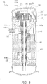
- FIG. 2 is a cross-sectional view of the compressor 10.
- the compressor 10 is a scroll compressor.
- the compressor 10 includes a pressure vessel 20, a compression element 30, a chamber forming member 34, a motor 40, a crankshaft 43, a first support member 44, and a second support member 45. Further, as shown in FIG. 3 , the compressor 10 includes an injection pipe connecting portion 51, an extension pipe 52, and a compression element connecting portion 53.
- the pressure vessel 20 has a strength that can withstand the high pressure possessed by the refrigerant.
- a suction pipe 21 for sucking in low-pressure gas refrigerant and a discharge pipe 22 for discharging high-pressure gas refrigerant are attached to the pressure vessel 20.
- the compression element 30 is a mechanism for compressing the gas refrigerant.
- the compression element 30 includes a fixed scroll 31 and a movable scroll 32.
- the fixed scroll 31 is directly or indirectly fixed to the pressure vessel 20.
- the movable scroll 32 is revolvable with respect to the fixed scroll.
- a compression chamber 33 is defined by the fixed scroll 31 and the movable scroll 32. As the movable scroll 32 revolves, the volume of the compression chamber 33 changes to thereby compress the gas refrigerant.
- the high-pressure gas refrigerant that has undergone the compression process exits the compression element 30 and moves toward a chamber 35 to be described later.
- the chamber forming member 34 divides the inner space of the pressure vessel 20 into a chamber 35 and a space 36 outside of the chamber.
- the chamber 35 is filled with the high-pressure gas refrigerant and is a space that functions as a flow path for the high-pressure gas refrigerant.
- the space outside the chamber is a space filled with the low-pressure gas refrigerant.
- the motor 40, the crankshaft 43, the first support member 44, and the second support member 45 are attached to the chamber 35.
- the motor 40 receives electric power to generate power for the compression element 30.
- the motor 40 includes a stator 41 and a rotor 42.
- the stator 41 is directly or indirectly fixed to the pressure vessel 20.
- the rotor 42 can rotate by performing a magnetic interaction with the stator 41.
- the crankshaft 43 transmits the power generated by the motor 40 to the compression element 30.
- the crankshaft 43 is fixed to the rotor 42 and rotates together with the rotor 42.
- the crankshaft 43 includes an eccentric portion 43a that is coupled to the movable scroll 32. As the crankshaft 43 rotates, the eccentric portion 43a revolves, thereby causing the movable scroll 32 to revolve.
- the first support member 44 directly or indirectly supports the fixed scroll 31.
- the first support member 44 is directly or indirectly fixed to the pressure vessel 20.
- the first support member 44 supports a first bearing 44b, and the first bearing 44b pivotally supports the crankshaft 43.
- the second support member 45 is directly or indirectly fixed to the pressure vessel 20.
- the second support member 45 supports a second bearing 45b, and the second bearing 45b pivotally supports the crankshaft 43.
- FIG. 3 is an enlarged cross-sectional view of the compressor 10.
- An injection pipe 69 of the refrigerant circuit 100 is connected to the injection pipe connecting portion 51 of the compressor 10.
- the injection pipe connecting portion 51 is connected to the extension pipe 52.
- the extension pipe 52 is connected to a compression element connecting portion 53.
- the injection pipe connecting portion 51 is a rigid body, and a first throttle portion S1 having a relatively small flow path cross-sectional area is formed therein.
- the extension pipe 52 is a metal pipe.
- the compression element connecting portion 53 is a rigid body, and an enlarged flow path portion E having a relatively large flow path cross-sectional area and a second throttle portion S2 having a relatively small flow path cross-sectional area are formed therein.
- the compression element connecting portion 53 is fixed to one or both of the pressure vessel 20 and the compression element 30.
- a distal end of the compression element connecting portion 53 is embedded in the fixed scroll 31. At this distal end, an end portion of the second throttle portion S2 forms an injection spray hole 54.
- a refrigerant path 31a that allows the second throttle portion and the compression chamber 33 to communicate with each other is formed in the fixed scroll 31.
- the injection spray hole 54 is connected to this refrigerant path 31a.
- At least a part of the second throttle portion S2 is provided in the pressure vessel 20.
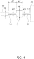
- FIG. 4 is a schematic diagram of an injection path.
- the refrigerant passes through each part that constitute the injection path in the following order: the injection pipe 69; the first throttle portion S1; the enlarged flow path portion E; the second throttle portion S2: and the compression chamber 33.
- the flow path cross-sectional areas of the injection pipe 69, the first throttle portion S1, the enlarged flow path portion E, and the second throttle portion S2 are denoted by AI, AS1, AE, and AS2, respectively.
- the lengths of the first throttle portion S1 and the enlarged flow path portion E are denoted by LS1 and LE, respectively.
- the flow path cross-sectional area AS1 of the first throttle portion S1 is narrower than both the flow path cross-sectional area AI of the injection pipe 69 and the flow path cross-sectional area AE of the enlarged flow path portion E.
- the flow path cross-sectional area AE of the enlarged flow path portion E is larger than both the flow path cross-sectional area AS1 of the first throttle portion S1 and the flow path cross-sectional area AS2 of the second throttle portion S2.
- the ratio AE/AS1 of the flow path cross-sectional areas AE and AS1 of the enlarged flow path portion E and the first throttle portion S1 is preferably 1.5 or more, and more preferably 4.0 or more.
- the ratio AE/AS2 of the flow path cross-sectional areas AE and AS2 of the enlarged flow path portion E and the second throttle portion S2 is preferable 1.5 or more, and more preferable 4.0 or more.
- the length LS1 of the first throttle portion S1 is not less than 20 mm and not more than 200 mm.
- the length LE of the enlarged flow path portion E is not less than 50 mm and not more than 400 mm.
- the first throttle portion S1, the enlarged flow path portion E, and the second throttle portion S2 have different flow path cross-sectional areas AS1, AE, and AS2, respectively.
- the path composed of the first throttle portion S1, the enlarged flow path portion E, and the second throttle portion S2 functions as a muffler and reduces the vibration of each portion caused by the pressure pulsation of the refrigerant.
- At least a part of the second throttle portion S2 is provided in the pressure vessel 20. Therefore, a part of the flow of the pulsating refrigerant passes through the compression vessel whereby the noise outside the pressure vessel is reduced.
- a portion of the enlarged flow path portion E and the second throttle portion are the same member. Therefore, it is easy to assemble a path functioning as a muffler.
- the ratio AE/AS1 of the flow path cross-sectional areas AE and AS1 of the enlarged flow path portion E and the first throttle portion S1 is 1.5 or more, preferably 4.0 or more. Therefore, vibrations are effectively reduced.
- the ratio AE/AS2 of the flow path cross-sectional areas AE and AS2 of the enlarged flow path portion E and the second throttle portion S2 is 1.5 or more, preferably 4.0 or more. Therefore, vibrations are more effectively reduced.
- the first throttle portion S1 ensures a predetermined length. Therefore, vibrations are more effectively reduced.
- the enlarged flow path portion E ensures the predetermined length LE. Therefore, vibrations are more effectively reduced.
- the refrigerant passes through the fixed scroll 31. Therefore, the refrigerant is stably supplied to the compression chamber 33 defined by the fixed scroll 31.
- a portion of the enlarged flow path portion E and the second throttle portion S2 are constituted by the same member, that is, the compression element connecting portion 53.
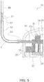
- the first throttle portion S1, the enlarged flow path portion E, and the second throttle portion S2 may be configured as separate members.
- the first throttle portion, the enlarged flow path portion, and the second throttle portion are configured as separate members. Therefore, a specification of the path functioning as the muffler can be easily modified by replacing the parts thereof.
- the enlarged flow path portion E is provided outside the pressure vessel 20.
- the enlarged flow path portion E may be at least partly provided in the pressure vessel 20.
- the enlarged flow path portion E is formed by the extension pipe 52 which is a single member.
- the enlarged flow path portion E is composed of a plurality of members 52a, 52b, and 52c.
- the enlarged flow path portion E is composed of the plurality of members 52a, 52b, and 52c. Therefore, it is easy to adjust a length, a flow path cross-sectional area, a radius of curvature, and the like of the enlarged flow path portion E by replacing the parts thereof.
- the first throttle portion S1 is merely composed of a rigid member.
- the first throttle portion S1 may be constituted by a commercially available controllable valve.
- a valve is one that is electrically, magnetically, or pneumatically driven so that the opening/closing of the valve and the opening degree thereof are controlled.
- the first throttle portion S1 is a valve whose opening/closing or opening degree is controlled. Consequently, the arrangement of the controllable valve enables the first throttle portion to be easily configured.
- the compressor 10 is a scroll compressor.
- the compressor 10 may be a rotary compressor or other types of compressor.
- the vibration of the injection pipe 69 is reduced by installing the injection pipe connecting portion 51, the extension pipe 52, and the compression element connecting portion 53.
- reducing the vibrations of the suction pipe 21 or the discharge pipe 22 may be realized by providing similar members in the suction pipe 21 or the discharge pipe 22.
- a valve structure may be provided in the second throttle portion S2.
- the valve structure may be a check valve.
- FIG. 9 is a view of a compressor 10 according to a second exemplary embodiment of the present invention.
- the compressor 10 according to the present exemplary embodiment differs from that of the first exemplary embodiment in that it includes not only the first throttle portion S1 and the second throttle portion S2 but also includes a third throttle portion S3.
- the third throttle portion S3 is connected to the second throttle portion S2.
- the third throttle portion S3 receives the refrigerant from the second throttle portion S2 and guides the refrigerant to the compression chamber 33.
- the third throttle portion S3 is constituted by a flow path 56.
- the flow path 56 may be formed integrally of the same member as the second throttle portion S2. Alternatively, the flow path 56 may be formed of a separate member from the second throttle portion S2.
- the first throttle portion S1, the enlarged flow path portion E, and the second throttle portion S2 are formed of separate members. Furthermore, the enlarged flow path portion E is constituted by a plurality of members 52a and 52b.
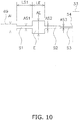
- FIG. 10 is a schematic diagram of an injection path. The respective symbols are the same as those in FIG. 4 of the first exemplary embodiment.
- the third throttle portion S3 has a flow path cross-sectional area AS3 that is narrower than the flow path cross-sectional area AS2 of the second throttle portion S2.
- the pulsation of the refrigerant can be further reduced when the refrigerant flows from the second throttle portion S2 to the third throttle portion S3.
- the first throttle portion S1, the enlarged flow path portion E, and the second throttle portion S2 are configured as separate members. Therefore, a specification of the path functioning as the muffler can be easily modified by replacing the parts thereof.
- the enlarged flow path portion E is constituted by the plurality of members 52a and 52b. Therefore, a length, a flow path cross-sectional area, a radius of curvature, and the like of the enlarged flow path portion E can be easily adjusted by replacing the parts thereof.
- a valve structure may be provided in the second throttle portion S2 or the third throttle portion S3.
- the valve structure may be a check valve.
- FIG. 11 is a view of a compressor according to a third exemplary embodiment.
- the present exemplary embodiment differs from the first exemplary embodiment in that the compression element connecting portion 53 is embedded in the first support member 44.
- the injection spray hole 54 communicates with the compression chamber 33 through the refrigerant path 44a formed in the first support member 44 and then through the refrigerant path 31a formed in the fixed scroll 31.
- the refrigerant passes through the first support member 44. Therefore, the refrigerant is stably supplied to the compression chamber 33 defined by the fixed scroll 31 via the first support member 44.
- FIG. 12 is a view of a compressor 10 according to a fourth exemplary embodiment.
- the present exemplary embodiment differs from the above described exemplary embodiment in that the compression element connecting portion 53 is embedded in the chamber forming member 34.
- the injection spray hole 54 communicates with the compression chamber 33 through the refrigerant path 34a formed in the chamber forming member 34 and then through the refrigerant path 31a formed in the fixed scroll 31.
- only the second throttle portion S2 is disposed in the pressure vessel 20.
- the refrigerant passes through the chamber forming member 34. Therefore, the refrigerant is stably supplied to the compression chamber 33 defined by the fixed scroll 31 via the chamber forming member 34.
- not only the second throttle portion S2 but also part of the enlarged flow path portion E may be disposed in the pressure vessel 20.
- Patent Literature 1 Japanese Laid-open Patent Application Publication No. 2010-185406
Landscapes
- Engineering & Computer Science (AREA)
- Mechanical Engineering (AREA)
- General Engineering & Computer Science (AREA)
- Applications Or Details Of Rotary Compressors (AREA)
- Compressor (AREA)
- Rotary Pumps (AREA)
Description
- The present invention relates to a compressor.
- A compressor is used in a refrigerant circuit such as an air conditioner. The compressor sucks a low-pressure gas refrigerant into its compression chamber and compresses the low-pressure gas refrigerant to produce a high-pressure gas refrigerant to discharge. Some compressors implement a technique called gas injection in order to improve the capacity of the refrigerant circuit. In the gas injection technique, a pipe called an injection pipe is connected to the compression chamber of the compressor. In a part of the refrigerant circuit, there exists an intermediate pressure gas refrigerant that indicates a pressure value between the low-pressure gas refrigerant and the high-pressure gas refrigerant. The injection pipe introduces the intermediate gas refrigerant into the compression chamber.
- The injection pipe often vibrates under pressure pulsation of the gas refrigerant. For this reason, noise is generated or excessive stress may be applied to the injection pipe. In order to reduce problems caused by such vibrations and stress, Patent Document 1 (Japanese Laid-Open Patent Application Publication No.
2010-185406 - Due to the weight of the muffler, piping such as the injection pipe connecting the compressor and the muffler receives a large stress, which may cause a problem in terms of reliability of the equipment.
- The present invention has been made to accomplish an objective of decreasing defects caused by vibrations and stress that a pipe receives in a compressor.
- A compressor according to a first aspect of the present invention compresses a low-pressure refrigerant sucked therein to discharge a high-pressure refrigerant. The compressor includes a first throttle portion, an enlarged flow path portion, a second throttle portion, and a compression element. The first throttle portion receives a refrigerant at an intermediate pressure from an injection pipe of a refrigerant circuit. The enlarged flow path portion receives the refrigerant from the first throttle portion. The second throttle portion receives the refrigerant from the enlarged flow path portion. The compression element has a compression chamber that receives the refrigerant from the second throttle portion. The first throttle portion has a flow path cross-sectional area that is narrower than both a flow path cross-sectional area of the injection pipe and a flow path cross-sectional area of the enlarged flow path portion. The second throttle portion has a flow path cross-sectional area that is narrower than the flow path cross-sectional area of the enlarged flow path portion.
- According to this configuration, the first throttle portion, the enlarged flow path portion, and the second throttle portion have different flow path cross-sectional areas. Therefore, the path composed of the first throttle portion, the enlarged flow path portion, and the second throttle portion functions as a muffler and reduces the vibrations of each portion caused by pressure pulsation of the refrigerant.
- A compressor according to a second aspect of the present invention is the compressor according to the first aspect of the present invention further including a pressure vessel that accommodates the compression element. At least a part of the second throttle portion is provided in the pressure vessel.
- According to this configuration, at least a part of the second throttle portion is provided in the pressure vessel. Since a part of the flow of the pulsating refrigerant passes through the pressure vessel, the noise outside the pressure vessel is reduced as a result.
- A compressor according to a third aspect of the present invention is the compressor according to the second aspect of the present invention, wherein at least a part of the enlarged flow path portion is provided in the pressure vessel.
- According to this configuration, at least a part of the enlarged flow path portion is provided in the pressure vessel. Therefore, a pressure fluctuation of the refrigerant flowing from the enlarged flow path portion to the second throttle portion occurs in the pressure vessel, whereby the noise outside the pressure vessel is reduced.
- A compressor according to a fourth aspect of the present invention is the compressor according to any one of the first aspect to the third aspect of the present invention, wherein the enlarged flow path portion and the second throttle portion are configured as the same member.
- According to this configuration, the enlarged flow path portion and the second throttle portion are the same member. Therefore, it is easy to assemble a path that functions as a muffler.
- A compressor according to a fifth aspect of the present invention is the compressor according to any one of the first aspect to the third aspect of the present invention, wherein the first throttle portion, the enlarged flow path portion, and the second throttle portion are configured as separate members.
- According to this configuration, the first throttle portion, the enlarged flow path portion, and the second throttle portion are configured as separate members. Therefore, a specification of the path functioning as the muffler can be easily modified by replacing the parts thereof.
- A compressor according to a sixth aspect of the present invention is the compressor according to any one of the first aspect to the fifth aspect of the present invention, wherein the enlarged flow path portion is composed of a plurality of members.
- According to this configuration, the enlarged flow path portion is composed of a plurality of members. Therefore, it is easy to adjust a length, a flow path cross-sectional area, a radius of curvature, and the like of the enlarged flow path portion by replacing the parts thereof.
- A compressor according to a seventh aspect of the present invention is the compressor according to any one of the first aspect to the sixth aspect of the present invention, wherein the flow path cross-sectional area of the enlarged flow path portion is 1.5 times or more, preferably 4.0 times or more, larger than the flow path cross-sectional area of the first throttle portion.
- According to this configuration, a ratio of the flow path cross-sectional area of the enlarged flow path portion to the first throttle portion is 1.5 times or more, preferably 4.0 times or more. Therefore, vibrations are effectively reduced.
- A compressor according to an eighth aspect of the present invention is the compressor according to any one of the first aspect to the seventh aspect of the present invention, wherein the flow path cross-sectional area of the enlarged flow path portion is 1.5 times or more, preferably 4.0 times or more, larger than the flow path cross-sectional area of the second throttle portion.
- According to this configuration, a ratio of the flow path cross-sectional area of the enlarged flow path portion to the second throttle portion is 1.5 times or more, preferably 4.0 times or more. Therefore, vibrations are more effectively reduced.
- A compressor according to a ninth aspect of the present invention is the compressor according to any one of the first aspect to the eighth aspect of the present invention, wherein a length of the first throttle portion is not less than 20 mm and not more than 200 mm.
- According to this configuration, the first throttle portion ensures a predetermined length. Therefore, vibrations are more effectively reduced.
- A compressor according to a tenth aspect of the present invention is the compressor according to any one of the first aspect to the ninth aspect of the present invention, wherein a length of the enlarged flow path portion is not less than 50 mm and not more than 400 mm.
- According to this configuration, the enlarged flow path portion ensures a predetermined length. Therefore, vibrations are more effectively reduced.
- A compressor according to an eleventh aspect of the present invention is the compressor according to any one of the first aspect to the tenth aspect of the present invention, wherein the compression element includes a fixed scroll and a movable scroll defining the compression chamber. The refrigerant that has exited the second throttle portion enters the compression chamber via the fixed scroll.
- According to this configuration, the refrigerant passes through the fixed scroll. Therefore, the refrigerant is stably supplied to the compression chamber defined by the fixed scroll.
- A compressor according to a twelfth aspect of the present invention is the compressor according to any one of the first aspect to the tenth aspect, wherein the compression element includes a fixed scroll and a movable scroll that define a compression chamber, and a support member that directly or indirectly supports the fixed scroll. The refrigerant that has exited the second throttle portion enters the compression chamber via the support member.
- According to this configuration, the refrigerant passes through the support member. Therefore, the refrigerant is stably supplied to the compression chamber defined by the fixed scroll via the support member.
- A compressor according to a thirteenth aspect of the present invention is the compressor according to any one of the first aspect to the tenth aspect of the present invention, wherein the compression element includes a fixed scroll and a movable scroll defining a compression chamber, and a chamber forming member for defining a chamber together with the fixed scroll. The chamber functions as a flow path for the high-pressure refrigerant discharged from the compression chamber. The refrigerant that has exited the second throttle portion enters the compression chamber via the chamber forming member.
- According to this configuration, the refrigerant passes through the chamber forming member. Therefore, the refrigerant is stably supplied to the compression chamber defined by the fixed scroll via the chamber forming member.
- A compressor according to a fourteenth aspect of the present invention is the compressor according to any one of the first aspect to the thirteenth aspect of the present invention further including a third throttle portion that receives the refrigerant from the second throttle portion and guides the refrigerant to the compression chamber. The third throttle portion has a flow path cross-sectional area that is narrower than the flow path cross-sectional area of the second throttle portion.
- According to this configuration, the compressor includes a third throttle portion. Therefore, when the refrigerant flows from the second throttle portion to the third throttle portion, the pulsation of the refrigerant can be further reduced.
- A compressor according to a fifteenth aspect of the present invention is the compressor according to any one of the first aspect to the fourteenth aspect of the present invention, wherein the first throttle portion includes a valve that is electrically, magnetically, or pneumatically driven.
- According to this configuration, the first throttle portion is a valve whose opening/closing and opening degree are controlled. Therefore, the arrangement of the controllable valve enables the first throttle portion to be easily configured.
- According to the compressor of the present invention, the vibrations of each part caused by the pressure pulsation of the refrigerant are reduced.
-
-
FIG. 1 is a schematic diagram illustrating arefrigerant circuit 100 of an air conditioner using acompressor 10 according to a first embodiment of the present invention. -
FIG. 2 is a cross-sectional view of thecompressor 10 according to the first embodiment of the present invention. -
FIG. 3 is an enlarged cross-sectional view of thecompressor 10. -
FIG. 4 is a schematic diagram of an injection path. -
FIG. 5 is an enlarged cross-sectional view of a compressor according to a first example modification of the first embodiment of the present invention. -
FIG. 6 is an enlarged cross-sectional view of a compressor according to a second example modification of the first embodiment of the present invention. -
FIG. 7 is an enlarged cross-sectional view of a compressor according to a third example modification of the first embodiment of the present invention. -
FIG. 8 is an enlarged cross-sectional view of a compressor according to a fourth example modification of the first embodiment of the present invention. -
FIG. 9 is an enlarged cross-sectional view of a compressor according to a second embodiment of the present invention. -
FIG. 10 is a schematic diagram of an injection path. -
FIG. 11 is an enlarged cross-sectional view of acompressor 10 according to a third embodiment of the present invention. -
FIG. 12 is an enlarged cross-sectional view of acompressor 10 according to a fourth embodiment of the present invention. -
FIG. 13 is an enlarged cross-sectional view of acompressor 10 according to a first example modification of the fourth embodiment of the present invention. - Hereinafter, compressors according to exemplary embodiments of the present invention will be described with reference to the drawings. It should be noted that a specific configuration of a compressor according to the present invention is not limited to the embodiments described hereinafter, can be appropriately changed without departing from the gist of the present invention.
-
FIG. 1 is a diagram of arefrigerant circuit 100 of an air conditioner in which acompressor 10 according to an exemplary embodiment of the present invention is used. Therefrigerant circuit 100 includes anoutdoor unit 60, anindoor unit 80, and arefrigerant piping 70. - The
outdoor unit 60 functions as a heat source. Theoutdoor unit 60 includes acompressor 10, a four-way switching valve 61, anoutdoor heat exchanger 62, anoutdoor expansion valve 63, aneconomizer heat exchanger 64, aninjection expansion valve 65, aliquid shutoff valve 67, and agas shutoff valve 68. - The
compressor 10 is a compressor for compressing a refrigerant that is a fluid. Thecompressor 10 compresses a gaseous low-pressure refrigerant sucked from asuction pipe 21 and discharges a gaseous high-pressure refrigerant from adischarge pipe 22. The four-way switching valve 61 forms a connection indicated by a solid line during a cooling operation and forms a connection indicated by a broken line during a heating operation. Theoutdoor heat exchanger 62 performs heat exchange between the refrigerant and the air using a fan (not shown), and functions as a condenser during the cooling operation and as an evaporator during the heating operation. Theoutdoor expansion valve 63 is a valve whose opening degree is adjustable, and functions as a decompressor of the refrigerant. Theliquid shutoff valve 67 and thegas shutoff valve 68 are openable and closable valves that are to be closed during maintenance or the like of the air conditioner. - The
economizer heat exchanger 64 supercools the liquid refrigerant discharged from the condenser of the refrigerant. Theeconomizer heat exchanger 64 includes a main path 64a and anauxiliary path 64b. The main path 64a is a path through which the liquid refrigerant to be subjected to supercooling passes. Theauxiliary path 64b is a path through which a gas refrigerant that acts as a cold heat source necessary for a supercooling operation passes. The gas refrigerant acting as this cold heat source is an intermediate pressure gas refrigerant produced by theinjection expansion valve 65 decompressing the liquid refrigerant. The intermediate pressure gas refrigerant leaving theauxiliary path 64b is guided to thecompressor 10 by aninjection pipe 69. - The
indoor unit 80 adjusts the temperature of the air in the room where there is a user present. Theindoor unit 80 includes anindoor heat exchanger 81 and an indoor expansion valve 82. Theindoor heat exchanger 81 performs heat exchange between the refrigerant and the air using a fan (not shown), and functions as an evaporator during the cooling operation and as a condenser during the heating operation. The indoor expansion valve 82 is a valve whose opening degree is adjustable, and functions as a decompressor of the refrigerant. - The
refrigerant piping 70 functions as a path for moving the refrigerant between theoutdoor unit 60 and theindoor unit 80. Therefrigerant piping 70 includes a liquidrefrigerant pipe 71 and agas refrigerant pipe 72. The liquidrefrigerant pipe 71 is a pipe for allowing theliquid shutoff valve 67 and the indoor expansion valve 82 to communicate with each other, and mainly moves the liquid refrigerant or the gas-liquid two-phase refrigerant. Thegas refrigerant pipe 72 is a pipe for allowing thegas shutoff valve 68 and theindoor heat exchanger 81 to communicate with each other and mainly moves the gas refrigerant. -
FIG. 2 is a cross-sectional view of thecompressor 10. Thecompressor 10 is a scroll compressor. Thecompressor 10 includes apressure vessel 20, acompression element 30, achamber forming member 34, a motor 40, acrankshaft 43, afirst support member 44, and asecond support member 45. Further, as shown inFIG. 3 , thecompressor 10 includes an injectionpipe connecting portion 51, anextension pipe 52, and a compressionelement connecting portion 53. - Returning to
FIG. 2 , housing the constituent parts of thecompressor 10 and the refrigerant, thepressure vessel 20 has a strength that can withstand the high pressure possessed by the refrigerant. Asuction pipe 21 for sucking in low-pressure gas refrigerant and adischarge pipe 22 for discharging high-pressure gas refrigerant are attached to thepressure vessel 20. - The
compression element 30 is a mechanism for compressing the gas refrigerant. Thecompression element 30 includes a fixedscroll 31 and amovable scroll 32. The fixedscroll 31 is directly or indirectly fixed to thepressure vessel 20. Themovable scroll 32 is revolvable with respect to the fixed scroll. Acompression chamber 33 is defined by the fixedscroll 31 and themovable scroll 32. As themovable scroll 32 revolves, the volume of thecompression chamber 33 changes to thereby compress the gas refrigerant. The high-pressure gas refrigerant that has undergone the compression process exits thecompression element 30 and moves toward achamber 35 to be described later. - The
chamber forming member 34 divides the inner space of thepressure vessel 20 into achamber 35 and aspace 36 outside of the chamber. Thechamber 35 is filled with the high-pressure gas refrigerant and is a space that functions as a flow path for the high-pressure gas refrigerant. The space outside the chamber is a space filled with the low-pressure gas refrigerant. The motor 40, thecrankshaft 43, thefirst support member 44, and thesecond support member 45 are attached to thechamber 35. - The motor 40 receives electric power to generate power for the
compression element 30. The motor 40 includes astator 41 and arotor 42. Thestator 41 is directly or indirectly fixed to thepressure vessel 20. Therotor 42 can rotate by performing a magnetic interaction with thestator 41. - The
crankshaft 43 transmits the power generated by the motor 40 to thecompression element 30. Thecrankshaft 43 is fixed to therotor 42 and rotates together with therotor 42. Thecrankshaft 43 includes aneccentric portion 43a that is coupled to themovable scroll 32. As thecrankshaft 43 rotates, theeccentric portion 43a revolves, thereby causing themovable scroll 32 to revolve. - The
first support member 44 directly or indirectly supports the fixedscroll 31. Thefirst support member 44 is directly or indirectly fixed to thepressure vessel 20. Thefirst support member 44 supports afirst bearing 44b, and thefirst bearing 44b pivotally supports thecrankshaft 43. - The
second support member 45 is directly or indirectly fixed to thepressure vessel 20. Thesecond support member 45 supports asecond bearing 45b, and thesecond bearing 45b pivotally supports thecrankshaft 43. -
FIG. 3 is an enlarged cross-sectional view of thecompressor 10. Aninjection pipe 69 of therefrigerant circuit 100 is connected to the injectionpipe connecting portion 51 of thecompressor 10. The injectionpipe connecting portion 51 is connected to theextension pipe 52. Theextension pipe 52 is connected to a compressionelement connecting portion 53. - The injection
pipe connecting portion 51 is a rigid body, and a first throttle portion S1 having a relatively small flow path cross-sectional area is formed therein. Theextension pipe 52 is a metal pipe. The compressionelement connecting portion 53 is a rigid body, and an enlarged flow path portion E having a relatively large flow path cross-sectional area and a second throttle portion S2 having a relatively small flow path cross-sectional area are formed therein. The compressionelement connecting portion 53 is fixed to one or both of thepressure vessel 20 and thecompression element 30. A distal end of the compressionelement connecting portion 53 is embedded in the fixedscroll 31. At this distal end, an end portion of the second throttle portion S2 forms aninjection spray hole 54. Arefrigerant path 31a that allows the second throttle portion and thecompression chamber 33 to communicate with each other is formed in the fixedscroll 31. Theinjection spray hole 54 is connected to thisrefrigerant path 31a. At least a part of the second throttle portion S2 is provided in thepressure vessel 20. -
FIG. 4 is a schematic diagram of an injection path. The refrigerant passes through each part that constitute the injection path in the following order: theinjection pipe 69; the first throttle portion S1; the enlarged flow path portion E; the second throttle portion S2: and thecompression chamber 33. The flow path cross-sectional areas of theinjection pipe 69, the first throttle portion S1, the enlarged flow path portion E, and the second throttle portion S2 are denoted by AI, AS1, AE, and AS2, respectively. The lengths of the first throttle portion S1 and the enlarged flow path portion E are denoted by LS1 and LE, respectively. - The flow path cross-sectional area AS1 of the first throttle portion S1 is narrower than both the flow path cross-sectional area AI of the
injection pipe 69 and the flow path cross-sectional area AE of the enlarged flow path portion E. The flow path cross-sectional area AE of the enlarged flow path portion E is larger than both the flow path cross-sectional area AS1 of the first throttle portion S1 and the flow path cross-sectional area AS2 of the second throttle portion S2. The ratio AE/AS1 of the flow path cross-sectional areas AE and AS1 of the enlarged flow path portion E and the first throttle portion S1 is preferably 1.5 or more, and more preferably 4.0 or more. The ratio AE/AS2 of the flow path cross-sectional areas AE and AS2 of the enlarged flow path portion E and the second throttle portion S2 is preferable 1.5 or more, and more preferable 4.0 or more. - The length LS1 of the first throttle portion S1 is not less than 20 mm and not more than 200 mm.
- The length LE of the enlarged flow path portion E is not less than 50 mm and not more than 400 mm.
- The first throttle portion S1, the enlarged flow path portion E, and the second throttle portion S2 have different flow path cross-sectional areas AS1, AE, and AS2, respectively. Thus, the path composed of the first throttle portion S1, the enlarged flow path portion E, and the second throttle portion S2 functions as a muffler and reduces the vibration of each portion caused by the pressure pulsation of the refrigerant.
- At least a part of the second throttle portion S2 is provided in the
pressure vessel 20. Therefore, a part of the flow of the pulsating refrigerant passes through the compression vessel whereby the noise outside the pressure vessel is reduced. - A portion of the enlarged flow path portion E and the second throttle portion are the same member. Therefore, it is easy to assemble a path functioning as a muffler.
- The ratio AE/AS1 of the flow path cross-sectional areas AE and AS1 of the enlarged flow path portion E and the first throttle portion S1 is 1.5 or more, preferably 4.0 or more. Therefore, vibrations are effectively reduced.
- The ratio AE/AS2 of the flow path cross-sectional areas AE and AS2 of the enlarged flow path portion E and the second throttle portion S2 is 1.5 or more, preferably 4.0 or more. Therefore, vibrations are more effectively reduced.
- The first throttle portion S1 ensures a predetermined length. Therefore, vibrations are more effectively reduced.
- The enlarged flow path portion E ensures the predetermined length LE. Therefore, vibrations are more effectively reduced.
- The refrigerant passes through the fixed
scroll 31. Therefore, the refrigerant is stably supplied to thecompression chamber 33 defined by the fixedscroll 31. - Hereinafter, modification examples of the present exemplary embodiment will be described.
- In the above described exemplary embodiment, a portion of the enlarged flow path portion E and the second throttle portion S2 are constituted by the same member, that is, the compression
element connecting portion 53. Alternatively, as shown inFIG. 5 , the first throttle portion S1, the enlarged flow path portion E, and the second throttle portion S2 may be configured as separate members. - According to this configuration, the first throttle portion, the enlarged flow path portion, and the second throttle portion are configured as separate members. Therefore, a specification of the path functioning as the muffler can be easily modified by replacing the parts thereof.
- In the above described exemplary embodiment, the enlarged flow path portion E is provided outside the
pressure vessel 20. Alternatively, as shown inFIG. 6 , the enlarged flow path portion E may be at least partly provided in thepressure vessel 20. - According to this configuration, at least a part of the enlarged flow path portion E is provided in the
pressure vessel 20. Therefore, a pressure fluctuation of the refrigerant flowing from the enlarged flow path portion E to the second throttle portion S2 occurs in thepressure vessel 20, whereby the noise outside thepressure vessel 20 is reduced. - In the first example modification shown in
FIG. 5 , the enlarged flow path portion E is formed by theextension pipe 52 which is a single member. As an alternative to this, as shown inFIG. 7 , a configuration may be adopted in which the enlarged flow path portion E is composed of a plurality ofmembers - According to this configuration, the enlarged flow path portion E is composed of the plurality of
members - In the above exemplary embodiment, the first throttle portion S1 is merely composed of a rigid member. As an alternative to this, as shown in
FIG. 8 , the first throttle portion S1 may be constituted by a commercially available controllable valve. Such a valve is one that is electrically, magnetically, or pneumatically driven so that the opening/closing of the valve and the opening degree thereof are controlled. - According to this configuration, the first throttle portion S1 is a valve whose opening/closing or opening degree is controlled. Consequently, the arrangement of the controllable valve enables the first throttle portion to be easily configured.
- In the above exemplary embodiment, the
compressor 10 is a scroll compressor. Alternatively, thecompressor 10 may be a rotary compressor or other types of compressor. - In the above exemplary embodiment, the vibration of the
injection pipe 69 is reduced by installing the injectionpipe connecting portion 51, theextension pipe 52, and the compressionelement connecting portion 53. As an alternative to this, reducing the vibrations of thesuction pipe 21 or thedischarge pipe 22 may be realized by providing similar members in thesuction pipe 21 or thedischarge pipe 22. - A valve structure may be provided in the second throttle portion S2. The valve structure may be a check valve.
-
FIG. 9 is a view of acompressor 10 according to a second exemplary embodiment of the present invention. Thecompressor 10 according to the present exemplary embodiment differs from that of the first exemplary embodiment in that it includes not only the first throttle portion S1 and the second throttle portion S2 but also includes a third throttle portion S3. The third throttle portion S3 is connected to the second throttle portion S2. The third throttle portion S3 receives the refrigerant from the second throttle portion S2 and guides the refrigerant to thecompression chamber 33. The third throttle portion S3 is constituted by aflow path 56. Theflow path 56 may be formed integrally of the same member as the second throttle portion S2. Alternatively, theflow path 56 may be formed of a separate member from the second throttle portion S2. - The first throttle portion S1, the enlarged flow path portion E, and the second throttle portion S2 are formed of separate members. Furthermore, the enlarged flow path portion E is constituted by a plurality of
members -
FIG. 10 is a schematic diagram of an injection path. The respective symbols are the same as those inFIG. 4 of the first exemplary embodiment. The third throttle portion S3 has a flow path cross-sectional area AS3 that is narrower than the flow path cross-sectional area AS2 of the second throttle portion S2. - With the inclusion of the third throttle portion S3 in the injection path, the pulsation of the refrigerant can be further reduced when the refrigerant flows from the second throttle portion S2 to the third throttle portion S3.
- The first throttle portion S1, the enlarged flow path portion E, and the second throttle portion S2 are configured as separate members. Therefore, a specification of the path functioning as the muffler can be easily modified by replacing the parts thereof.
- The enlarged flow path portion E is constituted by the plurality of
members - A valve structure may be provided in the second throttle portion S2 or the third throttle portion S3. The valve structure may be a check valve.
- The respective example modifications of the first exemplary embodiment may be applied independently or in combination to the present exemplary embodiment.
-
FIG. 11 is a view of a compressor according to a third exemplary embodiment. The present exemplary embodiment differs from the first exemplary embodiment in that the compressionelement connecting portion 53 is embedded in thefirst support member 44. Theinjection spray hole 54 communicates with thecompression chamber 33 through therefrigerant path 44a formed in thefirst support member 44 and then through therefrigerant path 31a formed in the fixedscroll 31. - According to this configuration, the refrigerant passes through the
first support member 44. Therefore, the refrigerant is stably supplied to thecompression chamber 33 defined by the fixedscroll 31 via thefirst support member 44. - The various modifications of the above exemplary embodiments may be applied independently or in combination to the present exemplary embodiment.
-
FIG. 12 is a view of acompressor 10 according to a fourth exemplary embodiment. The present exemplary embodiment differs from the above described exemplary embodiment in that the compressionelement connecting portion 53 is embedded in thechamber forming member 34. Theinjection spray hole 54 communicates with thecompression chamber 33 through therefrigerant path 34a formed in thechamber forming member 34 and then through therefrigerant path 31a formed in the fixedscroll 31. - In the present exemplary embodiment, only the second throttle portion S2 is disposed in the
pressure vessel 20. - According to this configuration, the refrigerant passes through the
chamber forming member 34. Therefore, the refrigerant is stably supplied to thecompression chamber 33 defined by the fixedscroll 31 via thechamber forming member 34. - As shown in
FIG. 13 , not only the second throttle portion S2 but also part of the enlarged flow path portion E may be disposed in thepressure vessel 20. - The various modifications of the above exemplary embodiments may be applied independently or in combination to the present exemplary embodiment.
-
- 10
- Compressor
- 20
- Pressure vessel
- 30
- Compression element
- 31
- Fixed scroll
- 32
- Movable scroll
- 33
- Compression chamber
- 34
- Chamber forming member
- 35
- Chamber
- 36
- space outside of the chamber
- 40
- Motor
- 51
- Injection pipe connecting portion
- 52
- Extension pipe
- 53
- Compression element connecting portion
- 54
- Injection spray hole
- 56
- Flow path
- 60
- Outdoor unit
- 62
- Outdoor heat exchanger
- 63
- Outdoor expansion valve
- 64
- Economizer heat exchanger
- 65
- Injection expansion valve
- 69
- Injection pipe
- 70
- Refrigerant communicating piping
- 80
- Indoor unit
- 81
- Indoor heat exchanger
- 82
- Indoor expansion valve
- 100
- Refrigerant circuit
- AE
- Flow path cross-sectional area of the enlarged flow path portion
- AI
- Flow path cross-sectional area of the injection pipe
- AS1
- Flow path cross-sectional area of the first throttle portion
- AS2
- Flow path cross-sectional area of the second throttle portion
- E
- Enlarged flow path portion
- LE
- Length of the enlarged flow path portion
- LS1
- Length of the first throttle portion
- S1
- First throttle portion
- S2
- Second throttle portion
- S3
- Third throttle portion
- <
Patent Literature 1> Japanese Laid-open Patent Application Publication No.2010-185406
Claims (15)
- A compressor (10) that compresses a low-pressure refrigerant sucked therein to produce a high-pressure refrigerant to discharge, the compressor (10) comprising:a first throttle portion (S1) for receiving a refrigerant at an intermediate pressure from an injection pipe (69) of a refrigerant circuit (100);an enlarged flow path portion (E) for receiving the refrigerant from the first throttle portion;a second throttle portion (S2) for receiving the refrigerant from the enlarged flow path portion; anda compression element (30) including a compression chamber (33) for receiving the refrigerant from the second throttle portion,the first throttle portion having a flow path cross-sectional area (AS1) that is narrower than both a flow path cross-sectional area (AI) of the injection pipe and a flow path cross-sectional area (AE) of the enlarged flow path portion,the second throttle portion having a flow path cross-sectional area (AS2) that is narrower than the flow path cross-sectional area (AE) of the enlarged flow path portion.
- The compressor according to claim 1 further comprisinga pressure vessel (20) for accommodating the compression element, whereinat least a part of the second throttle portion is provided in the pressure vessel.
- The compressor according to claim 2, wherein
at least a part of the enlarged flow path portion is provided in the pressure vessel. - The compressor according to any one of claims 1 to 3, wherein
the enlarged flow path portion and the second throttle portion are configured as the same member. - The compressor according to any one of claims 1 to 3, wherein
the first throttle portion, the enlarged flow path portion, and the second throttle portion are each configured as separate members. - The compressor according to any one of claims 1 to 5, wherein
the enlarged flow path portion is composed of a plurality of members. - The compressor according to any one of claims 1 to 6, wherein
the flow path cross-sectional area (AE) of the enlarged flow path portion is 1.5 times or more, preferably 4.0 times or more, larger than the flow path cross-sectional area (AS1) of the first throttle portion. - The compressor according to any one of claims 1 to 7, wherein
the flow path cross-sectional area (AE) of the enlarged flow path portion is 1.5 times or more, preferably 4.0 times or more, larger than the flow path cross-sectional area (AS2) of the second throttle portion. - The compressor according to any one of claims 1 to 8, wherein
the first throttle has a length (LS1) that is not less than 20 mm and not more than 200 mm. - The compressor according to any one of claims 1 to 9, wherein
the enlarged flow path portion has a length (LE) that is not less than 50 mm and not more than 400 mm. - The compressor according to any one of claims 1 to 10, whereinthe compression element includes a fixed scroll (31) and a movable scroll (32) that define the compression chamber; andthe refrigerant that has exited the second throttle portion enters the compression chamber via the fixed scroll.
- The compressor according to any one of claims 1 to 10, whereinthe compression element includes a fixed scroll (31) and a movable scroll (32) that define the compression chamber, and a support member (44) that directly or indirectly supports the fixed scroll, andthe refrigerant that has exited the second throttle portion enters the compression chamber via the support member.
- The compressor according to any one of claims 1 to 10, whereinthe compression element includes a fixed scroll (31) and a movable scroll (32) that define the compression chamber, and a chamber forming member (34) that, together with the fixed scroll, defines a chamber (35),the chamber functions as a flow path for the high-pressure refrigerant discharged from the compression chamber, andthe refrigerant that has exited the second throttle portion enters the compression chamber via the chamber forming member.
- The compressor according to any one of claims 1 to 13 further comprisinga third throttle portion (S3) for receiving the refrigerant from the second throttle portion and guiding the refrigerant to the compression chamber, whereinthe third throttle portion has a flow path cross-sectional area (AS3) that is narrower than the flow path cross-sectional area (AS2) of the second throttle portion.
- The compressor according to any one of claims 1 to 14, wherein
the first throttle portion includes a valve that is electrically, magnetically, or pneumatically driven.
Applications Claiming Priority (2)
| Application Number | Priority Date | Filing Date | Title |
|---|---|---|---|
| JP2016139666 | 2016-07-14 | ||
| PCT/JP2017/025761 WO2018012623A1 (en) | 2016-07-14 | 2017-07-14 | Compressor having muffler function |
Publications (3)
| Publication Number | Publication Date |
|---|---|
| EP3486487A4 EP3486487A4 (en) | 2019-05-22 |
| EP3486487A1 true EP3486487A1 (en) | 2019-05-22 |
| EP3486487B1 EP3486487B1 (en) | 2020-09-09 |
Family
ID=60953109
Family Applications (1)
| Application Number | Title | Priority Date | Filing Date |
|---|---|---|---|
| EP17827746.3A Active EP3486487B1 (en) | 2016-07-14 | 2017-07-14 | Compressor having muffler function |
Country Status (6)
| Country | Link |
|---|---|
| US (1) | US10989196B2 (en) |
| EP (1) | EP3486487B1 (en) |
| JP (1) | JP6311830B2 (en) |
| CN (1) | CN109477475B (en) |
| ES (1) | ES2821929T3 (en) |
| WO (1) | WO2018012623A1 (en) |
Families Citing this family (10)
| Publication number | Priority date | Publication date | Assignee | Title |
|---|---|---|---|---|
| US11655816B2 (en) * | 2015-05-08 | 2023-05-23 | Danfoss Power Solutions Gmbh & Co. Ohg | Fluid working systems |
| CN111989493A (en) * | 2018-04-27 | 2020-11-24 | 三菱电机株式会社 | scroll compressor |
| CN110118421B (en) * | 2019-04-30 | 2021-04-09 | 广东美的制冷设备有限公司 | Air conditioner and control method thereof, circulation pipeline and readable storage medium |
| CN210949108U (en) * | 2019-09-29 | 2020-07-07 | 丹佛斯(天津)有限公司 | Scroll compressor having a plurality of scroll members |
| CN112539174A (en) * | 2020-12-22 | 2021-03-23 | 广东美芝制冷设备有限公司 | Enthalpy-increasing pulsation attenuation device, scroll compressor and air conditioning system |
| CN112539175A (en) * | 2020-12-22 | 2021-03-23 | 广东美芝制冷设备有限公司 | Enthalpy-increasing pressure pulsation attenuation device, scroll compressor and air conditioning system |
| JP7488993B2 (en) | 2021-03-22 | 2024-05-23 | 株式会社豊田自動織機 | Scroll Compressor |
| CN118339381A (en) * | 2021-12-10 | 2024-07-12 | 大金工业株式会社 | Tube assembly, compressor, refrigeration device, and method for manufacturing tube assembly |
| EP4446584B1 (en) | 2021-12-10 | 2026-04-01 | Daikin Industries, Ltd. | Pipe assembly, compressor, refrigeration device, and method for manufacturing pipe assembly |
| JP7415190B2 (en) * | 2021-12-10 | 2024-01-17 | ダイキン工業株式会社 | Pipe assembly, compressor, refrigeration device, and method for manufacturing the pipe assembly |
Family Cites Families (11)
| Publication number | Priority date | Publication date | Assignee | Title |
|---|---|---|---|---|
| JPS58148290A (en) * | 1982-02-26 | 1983-09-03 | Hitachi Ltd | Refrigerator with acroll compressor |
| JPH0460191A (en) * | 1990-06-28 | 1992-02-26 | Kobe Steel Ltd | Silencing structure of screw compressor |
| JPH05157046A (en) * | 1991-12-03 | 1993-06-22 | Matsushita Refrig Co Ltd | Silencer for closed electric compressor |
| JPH1037879A (en) * | 1996-07-25 | 1998-02-13 | Mitsubishi Electric Corp | Scroll compressor |
| US6053715A (en) * | 1997-09-30 | 2000-04-25 | Matsushita Electric Industrial Co., Ltd. | Scroll type compressor |
| JP2000337261A (en) * | 1999-05-26 | 2000-12-05 | Funai Electric Co Ltd | Compressor |
| DE10323526B3 (en) * | 2003-05-24 | 2005-02-03 | Danfoss Compressors Gmbh | Suction muffler for a hermetic refrigerant compressor |
| US8985976B2 (en) * | 2008-05-19 | 2015-03-24 | Panasonic Intellectual Property Management Co., Ltd. | Two-stage rotary expander, expander-integrated compressor, and refrigeration cycle apparatus |
| JP5683075B2 (en) * | 2009-02-13 | 2015-03-11 | 三菱重工業株式会社 | Injection tube |
| JP6164427B2 (en) * | 2014-03-28 | 2017-07-19 | 株式会社富士通ゼネラル | Rotary compressor |
| JP2017025761A (en) | 2015-07-21 | 2017-02-02 | 株式会社デンソー | Engine control device |
-
2017
- 2017-07-14 US US16/317,219 patent/US10989196B2/en active Active
- 2017-07-14 WO PCT/JP2017/025761 patent/WO2018012623A1/en not_active Ceased
- 2017-07-14 CN CN201780042722.5A patent/CN109477475B/en active Active
- 2017-07-14 ES ES17827746T patent/ES2821929T3/en active Active
- 2017-07-14 EP EP17827746.3A patent/EP3486487B1/en active Active
- 2017-07-14 JP JP2017137695A patent/JP6311830B2/en active Active
Also Published As
| Publication number | Publication date |
|---|---|
| EP3486487A4 (en) | 2019-05-22 |
| US10989196B2 (en) | 2021-04-27 |
| CN109477475A (en) | 2019-03-15 |
| EP3486487B1 (en) | 2020-09-09 |
| JP6311830B2 (en) | 2018-04-18 |
| JP2018017233A (en) | 2018-02-01 |
| ES2821929T3 (en) | 2021-04-28 |
| CN109477475B (en) | 2022-06-17 |
| US20190316589A1 (en) | 2019-10-17 |
| WO2018012623A1 (en) | 2018-01-18 |
Similar Documents
| Publication | Publication Date | Title |
|---|---|---|
| EP3486487B1 (en) | Compressor having muffler function | |
| EP2634432B1 (en) | Screw compressor | |
| US6189335B1 (en) | Multi-stage compressing refrigeration device and refrigerator using the device | |
| US8590323B2 (en) | Turbo compressor and refrigerator | |
| US10227980B2 (en) | Motor-driven compressor including injection port that delivers intermediate pressure refrigerant to compression chamber | |
| US20110271699A1 (en) | Frequency variable compressor and control method thereof | |
| CN100387914C (en) | Freezers and Refrigerators | |
| EP1684027A2 (en) | Refrigerating apparatus and refrigerator | |
| EP2416011B1 (en) | Discharge muffler and two-stage compressor with discharge muffler | |
| CN104379937A (en) | Hermetic Compressor and Heat Pump Units | |
| EP3835685A1 (en) | Multistage compression system | |
| JP2001091071A (en) | Multi-stage compression refrigerating machine | |
| EP3859233A1 (en) | Multistage compression system | |
| WO2010092933A1 (en) | Injection pipe | |
| EP3859234B1 (en) | Multistage compression system | |
| EP3936787A1 (en) | Refrigeration cycle device | |
| EP3859232A1 (en) | Multistage compression system | |
| US8601832B2 (en) | Turbo compressor and refrigerator | |
| EP2048457B1 (en) | Refrigeration device | |
| EP3263901A1 (en) | Scroll-type compressor | |
| CN111417783A (en) | Double rotary compressor and refrigeration cycle device | |
| JPH06330857A (en) | Enclosed compressor | |
| EP4461969A1 (en) | Turbo fluid machine and refrigeration device | |
| JPH07167513A (en) | Refrigeration equipment | |
| JPH0730962B2 (en) | Two-stage compression refrigeration cycle |
Legal Events
| Date | Code | Title | Description |
|---|---|---|---|
| STAA | Information on the status of an ep patent application or granted ep patent |
Free format text: STATUS: THE INTERNATIONAL PUBLICATION HAS BEEN MADE |
|
| PUAI | Public reference made under article 153(3) epc to a published international application that has entered the european phase |
Free format text: ORIGINAL CODE: 0009012 |
|
| STAA | Information on the status of an ep patent application or granted ep patent |
Free format text: STATUS: REQUEST FOR EXAMINATION WAS MADE |
|
| 17P | Request for examination filed |
Effective date: 20190207 |
|
| A4 | Supplementary search report drawn up and despatched |
Effective date: 20190327 |
|
| AK | Designated contracting states |
Kind code of ref document: A1 Designated state(s): AL AT BE BG CH CY CZ DE DK EE ES FI FR GB GR HR HU IE IS IT LI LT LU LV MC MK MT NL NO PL PT RO RS SE SI SK SM TR |
|
| AX | Request for extension of the european patent |
Extension state: BA ME |
|
| DAV | Request for validation of the european patent (deleted) | ||
| DAX | Request for extension of the european patent (deleted) | ||
| GRAP | Despatch of communication of intention to grant a patent |
Free format text: ORIGINAL CODE: EPIDOSNIGR1 |
|
| STAA | Information on the status of an ep patent application or granted ep patent |
Free format text: STATUS: GRANT OF PATENT IS INTENDED |
|
| INTG | Intention to grant announced |
Effective date: 20191203 |
|
| GRAJ | Information related to disapproval of communication of intention to grant by the applicant or resumption of examination proceedings by the epo deleted |
Free format text: ORIGINAL CODE: EPIDOSDIGR1 |
|
| STAA | Information on the status of an ep patent application or granted ep patent |
Free format text: STATUS: REQUEST FOR EXAMINATION WAS MADE |
|
| INTC | Intention to grant announced (deleted) | ||
| GRAS | Grant fee paid |
Free format text: ORIGINAL CODE: EPIDOSNIGR3 |
|
| STAA | Information on the status of an ep patent application or granted ep patent |
Free format text: STATUS: GRANT OF PATENT IS INTENDED |
|
| GRAP | Despatch of communication of intention to grant a patent |
Free format text: ORIGINAL CODE: EPIDOSNIGR1 |
|
| GRAJ | Information related to disapproval of communication of intention to grant by the applicant or resumption of examination proceedings by the epo deleted |
Free format text: ORIGINAL CODE: EPIDOSDIGR1 |
|
| GRAL | Information related to payment of fee for publishing/printing deleted |
Free format text: ORIGINAL CODE: EPIDOSDIGR3 |
|
| GRAR | Information related to intention to grant a patent recorded |
Free format text: ORIGINAL CODE: EPIDOSNIGR71 |
|
| GRAS | Grant fee paid |
Free format text: ORIGINAL CODE: EPIDOSNIGR3 |
|
| INTG | Intention to grant announced |
Effective date: 20200507 |
|
| INTG | Intention to grant announced |
Effective date: 20200515 |
|
| GRAJ | Information related to disapproval of communication of intention to grant by the applicant or resumption of examination proceedings by the epo deleted |
Free format text: ORIGINAL CODE: EPIDOSDIGR1 |
|
| GRAR | Information related to intention to grant a patent recorded |
Free format text: ORIGINAL CODE: EPIDOSNIGR71 |
|
| GRAS | Grant fee paid |
Free format text: ORIGINAL CODE: EPIDOSNIGR3 |
|
| GRAA | (expected) grant |
Free format text: ORIGINAL CODE: 0009210 |
|
| STAA | Information on the status of an ep patent application or granted ep patent |
Free format text: STATUS: THE PATENT HAS BEEN GRANTED |
|
| AK | Designated contracting states |
Kind code of ref document: B1 Designated state(s): AL AT BE BG CH CY CZ DE DK EE ES FI FR GB GR HR HU IE IS IT LI LT LU LV MC MK MT NL NO PL PT RO RS SE SI SK SM TR |
|
| INTG | Intention to grant announced |
Effective date: 20200731 |
|
| REG | Reference to a national code |
Ref country code: GB Ref legal event code: FG4D |
|
| REG | Reference to a national code |
Ref country code: AT Ref legal event code: REF Ref document number: 1311900 Country of ref document: AT Kind code of ref document: T Effective date: 20200915 Ref country code: CH Ref legal event code: EP |
|
| REG | Reference to a national code |
Ref country code: IE Ref legal event code: FG4D |
|
| REG | Reference to a national code |
Ref country code: DE Ref legal event code: R096 Ref document number: 602017023511 Country of ref document: DE |
|
| REG | Reference to a national code |
Ref country code: LT Ref legal event code: MG4D |
|
| PG25 | Lapsed in a contracting state [announced via postgrant information from national office to epo] |
Ref country code: LT Free format text: LAPSE BECAUSE OF FAILURE TO SUBMIT A TRANSLATION OF THE DESCRIPTION OR TO PAY THE FEE WITHIN THE PRESCRIBED TIME-LIMIT Effective date: 20200909 Ref country code: HR Free format text: LAPSE BECAUSE OF FAILURE TO SUBMIT A TRANSLATION OF THE DESCRIPTION OR TO PAY THE FEE WITHIN THE PRESCRIBED TIME-LIMIT Effective date: 20200909 Ref country code: SE Free format text: LAPSE BECAUSE OF FAILURE TO SUBMIT A TRANSLATION OF THE DESCRIPTION OR TO PAY THE FEE WITHIN THE PRESCRIBED TIME-LIMIT Effective date: 20200909 Ref country code: BG Free format text: LAPSE BECAUSE OF FAILURE TO SUBMIT A TRANSLATION OF THE DESCRIPTION OR TO PAY THE FEE WITHIN THE PRESCRIBED TIME-LIMIT Effective date: 20201209 Ref country code: GR Free format text: LAPSE BECAUSE OF FAILURE TO SUBMIT A TRANSLATION OF THE DESCRIPTION OR TO PAY THE FEE WITHIN THE PRESCRIBED TIME-LIMIT Effective date: 20201210 Ref country code: FI Free format text: LAPSE BECAUSE OF FAILURE TO SUBMIT A TRANSLATION OF THE DESCRIPTION OR TO PAY THE FEE WITHIN THE PRESCRIBED TIME-LIMIT Effective date: 20200909 Ref country code: NO Free format text: LAPSE BECAUSE OF FAILURE TO SUBMIT A TRANSLATION OF THE DESCRIPTION OR TO PAY THE FEE WITHIN THE PRESCRIBED TIME-LIMIT Effective date: 20201209 |
|
| REG | Reference to a national code |
Ref country code: AT Ref legal event code: MK05 Ref document number: 1311900 Country of ref document: AT Kind code of ref document: T Effective date: 20200909 |
|
| REG | Reference to a national code |
Ref country code: NL Ref legal event code: MP Effective date: 20200909 |
|
| PG25 | Lapsed in a contracting state [announced via postgrant information from national office to epo] |
Ref country code: RS Free format text: LAPSE BECAUSE OF FAILURE TO SUBMIT A TRANSLATION OF THE DESCRIPTION OR TO PAY THE FEE WITHIN THE PRESCRIBED TIME-LIMIT Effective date: 20200909 Ref country code: PL Free format text: LAPSE BECAUSE OF FAILURE TO SUBMIT A TRANSLATION OF THE DESCRIPTION OR TO PAY THE FEE WITHIN THE PRESCRIBED TIME-LIMIT Effective date: 20200909 Ref country code: LV Free format text: LAPSE BECAUSE OF FAILURE TO SUBMIT A TRANSLATION OF THE DESCRIPTION OR TO PAY THE FEE WITHIN THE PRESCRIBED TIME-LIMIT Effective date: 20200909 |
|
| REG | Reference to a national code |
Ref country code: ES Ref legal event code: FG2A Ref document number: 2821929 Country of ref document: ES Kind code of ref document: T3 Effective date: 20210428 |
|
| PG25 | Lapsed in a contracting state [announced via postgrant information from national office to epo] |
Ref country code: EE Free format text: LAPSE BECAUSE OF FAILURE TO SUBMIT A TRANSLATION OF THE DESCRIPTION OR TO PAY THE FEE WITHIN THE PRESCRIBED TIME-LIMIT Effective date: 20200909 Ref country code: CZ Free format text: LAPSE BECAUSE OF FAILURE TO SUBMIT A TRANSLATION OF THE DESCRIPTION OR TO PAY THE FEE WITHIN THE PRESCRIBED TIME-LIMIT Effective date: 20200909 Ref country code: RO Free format text: LAPSE BECAUSE OF FAILURE TO SUBMIT A TRANSLATION OF THE DESCRIPTION OR TO PAY THE FEE WITHIN THE PRESCRIBED TIME-LIMIT Effective date: 20200909 Ref country code: PT Free format text: LAPSE BECAUSE OF FAILURE TO SUBMIT A TRANSLATION OF THE DESCRIPTION OR TO PAY THE FEE WITHIN THE PRESCRIBED TIME-LIMIT Effective date: 20210111 Ref country code: SM Free format text: LAPSE BECAUSE OF FAILURE TO SUBMIT A TRANSLATION OF THE DESCRIPTION OR TO PAY THE FEE WITHIN THE PRESCRIBED TIME-LIMIT Effective date: 20200909 |
|
| PG25 | Lapsed in a contracting state [announced via postgrant information from national office to epo] |
Ref country code: IS Free format text: LAPSE BECAUSE OF FAILURE TO SUBMIT A TRANSLATION OF THE DESCRIPTION OR TO PAY THE FEE WITHIN THE PRESCRIBED TIME-LIMIT Effective date: 20210109 Ref country code: AT Free format text: LAPSE BECAUSE OF FAILURE TO SUBMIT A TRANSLATION OF THE DESCRIPTION OR TO PAY THE FEE WITHIN THE PRESCRIBED TIME-LIMIT Effective date: 20200909 Ref country code: AL Free format text: LAPSE BECAUSE OF FAILURE TO SUBMIT A TRANSLATION OF THE DESCRIPTION OR TO PAY THE FEE WITHIN THE PRESCRIBED TIME-LIMIT Effective date: 20200909 |
|
| REG | Reference to a national code |
Ref country code: DE Ref legal event code: R097 Ref document number: 602017023511 Country of ref document: DE |
|
| PG25 | Lapsed in a contracting state [announced via postgrant information from national office to epo] |
Ref country code: SK Free format text: LAPSE BECAUSE OF FAILURE TO SUBMIT A TRANSLATION OF THE DESCRIPTION OR TO PAY THE FEE WITHIN THE PRESCRIBED TIME-LIMIT Effective date: 20200909 |
|
| PLBE | No opposition filed within time limit |
Free format text: ORIGINAL CODE: 0009261 |
|
| STAA | Information on the status of an ep patent application or granted ep patent |
Free format text: STATUS: NO OPPOSITION FILED WITHIN TIME LIMIT |
|
| 26N | No opposition filed |
Effective date: 20210610 |
|
| PG25 | Lapsed in a contracting state [announced via postgrant information from national office to epo] |
Ref country code: DK Free format text: LAPSE BECAUSE OF FAILURE TO SUBMIT A TRANSLATION OF THE DESCRIPTION OR TO PAY THE FEE WITHIN THE PRESCRIBED TIME-LIMIT Effective date: 20200909 Ref country code: SI Free format text: LAPSE BECAUSE OF FAILURE TO SUBMIT A TRANSLATION OF THE DESCRIPTION OR TO PAY THE FEE WITHIN THE PRESCRIBED TIME-LIMIT Effective date: 20200909 |
|
| REG | Reference to a national code |
Ref country code: CH Ref legal event code: PL |
|
| PG25 | Lapsed in a contracting state [announced via postgrant information from national office to epo] |
Ref country code: MC Free format text: LAPSE BECAUSE OF FAILURE TO SUBMIT A TRANSLATION OF THE DESCRIPTION OR TO PAY THE FEE WITHIN THE PRESCRIBED TIME-LIMIT Effective date: 20200909 |
|
| REG | Reference to a national code |
Ref country code: BE Ref legal event code: MM Effective date: 20210731 |
|
| PG25 | Lapsed in a contracting state [announced via postgrant information from national office to epo] |
Ref country code: LI Free format text: LAPSE BECAUSE OF NON-PAYMENT OF DUE FEES Effective date: 20210731 Ref country code: CH Free format text: LAPSE BECAUSE OF NON-PAYMENT OF DUE FEES Effective date: 20210731 |
|
| PG25 | Lapsed in a contracting state [announced via postgrant information from national office to epo] |
Ref country code: LU Free format text: LAPSE BECAUSE OF NON-PAYMENT OF DUE FEES Effective date: 20210714 |
|
| PG25 | Lapsed in a contracting state [announced via postgrant information from national office to epo] |
Ref country code: IE Free format text: LAPSE BECAUSE OF NON-PAYMENT OF DUE FEES Effective date: 20210714 Ref country code: BE Free format text: LAPSE BECAUSE OF NON-PAYMENT OF DUE FEES Effective date: 20210731 |
|
| PG25 | Lapsed in a contracting state [announced via postgrant information from national office to epo] |
Ref country code: NL Free format text: LAPSE BECAUSE OF NON-PAYMENT OF DUE FEES Effective date: 20200923 Ref country code: CY Free format text: LAPSE BECAUSE OF FAILURE TO SUBMIT A TRANSLATION OF THE DESCRIPTION OR TO PAY THE FEE WITHIN THE PRESCRIBED TIME-LIMIT Effective date: 20200909 |
|
| P01 | Opt-out of the competence of the unified patent court (upc) registered |
Effective date: 20230525 |
|
| PG25 | Lapsed in a contracting state [announced via postgrant information from national office to epo] |
Ref country code: HU Free format text: LAPSE BECAUSE OF FAILURE TO SUBMIT A TRANSLATION OF THE DESCRIPTION OR TO PAY THE FEE WITHIN THE PRESCRIBED TIME-LIMIT; INVALID AB INITIO Effective date: 20170714 |
|
| PG25 | Lapsed in a contracting state [announced via postgrant information from national office to epo] |
Ref country code: MK Free format text: LAPSE BECAUSE OF FAILURE TO SUBMIT A TRANSLATION OF THE DESCRIPTION OR TO PAY THE FEE WITHIN THE PRESCRIBED TIME-LIMIT Effective date: 20200909 |
|
| PG25 | Lapsed in a contracting state [announced via postgrant information from national office to epo] |
Ref country code: MT Free format text: LAPSE BECAUSE OF FAILURE TO SUBMIT A TRANSLATION OF THE DESCRIPTION OR TO PAY THE FEE WITHIN THE PRESCRIBED TIME-LIMIT Effective date: 20200909 |
|
| PGFP | Annual fee paid to national office [announced via postgrant information from national office to epo] |
Ref country code: GB Payment date: 20250529 Year of fee payment: 9 |
|
| PGFP | Annual fee paid to national office [announced via postgrant information from national office to epo] |
Ref country code: FR Payment date: 20250610 Year of fee payment: 9 |
|
| PGFP | Annual fee paid to national office [announced via postgrant information from national office to epo] |
Ref country code: ES Payment date: 20250801 Year of fee payment: 9 |
|
| PGFP | Annual fee paid to national office [announced via postgrant information from national office to epo] |
Ref country code: DE Payment date: 20250528 Year of fee payment: 9 |
|
| PGFP | Annual fee paid to national office [announced via postgrant information from national office to epo] |
Ref country code: TR Payment date: 20250704 Year of fee payment: 9 Ref country code: IT Payment date: 20250623 Year of fee payment: 9 |