EP3486457A1 - Heat exhaust system for on-aircraft electric generator - Google Patents
Heat exhaust system for on-aircraft electric generator Download PDFInfo
- Publication number
- EP3486457A1 EP3486457A1 EP17845714.9A EP17845714A EP3486457A1 EP 3486457 A1 EP3486457 A1 EP 3486457A1 EP 17845714 A EP17845714 A EP 17845714A EP 3486457 A1 EP3486457 A1 EP 3486457A1
- Authority
- EP
- European Patent Office
- Prior art keywords
- electric generator
- heat
- fuel
- engine
- flow rate
- Prior art date
- Legal status (The legal status is an assumption and is not a legal conclusion. Google has not performed a legal analysis and makes no representation as to the accuracy of the status listed.)
- Granted
Links
Images

Classifications
-
- B—PERFORMING OPERATIONS; TRANSPORTING
- B64—AIRCRAFT; AVIATION; COSMONAUTICS
- B64D—EQUIPMENT FOR FITTING IN OR TO AIRCRAFT; FLIGHT SUITS; PARACHUTES; ARRANGEMENT OR MOUNTING OF POWER PLANTS OR PROPULSION TRANSMISSIONS IN AIRCRAFT
- B64D41/00—Power installations for auxiliary purposes
-
- F—MECHANICAL ENGINEERING; LIGHTING; HEATING; WEAPONS; BLASTING
- F02—COMBUSTION ENGINES; HOT-GAS OR COMBUSTION-PRODUCT ENGINE PLANTS
- F02C—GAS-TURBINE PLANTS; AIR INTAKES FOR JET-PROPULSION PLANTS; CONTROLLING FUEL SUPPLY IN AIR-BREATHING JET-PROPULSION PLANTS
- F02C7/00—Features, components parts, details or accessories, not provided for in, or of interest apart form groups F02C1/00 - F02C6/00; Air intakes for jet-propulsion plants
- F02C7/12—Cooling of plants
- F02C7/16—Cooling of plants characterised by cooling medium
-
- F—MECHANICAL ENGINEERING; LIGHTING; HEATING; WEAPONS; BLASTING
- F02—COMBUSTION ENGINES; HOT-GAS OR COMBUSTION-PRODUCT ENGINE PLANTS
- F02C—GAS-TURBINE PLANTS; AIR INTAKES FOR JET-PROPULSION PLANTS; CONTROLLING FUEL SUPPLY IN AIR-BREATHING JET-PROPULSION PLANTS
- F02C7/00—Features, components parts, details or accessories, not provided for in, or of interest apart form groups F02C1/00 - F02C6/00; Air intakes for jet-propulsion plants
- F02C7/22—Fuel supply systems
- F02C7/224—Heating fuel before feeding to the burner
-
- F—MECHANICAL ENGINEERING; LIGHTING; HEATING; WEAPONS; BLASTING
- F02—COMBUSTION ENGINES; HOT-GAS OR COMBUSTION-PRODUCT ENGINE PLANTS
- F02C—GAS-TURBINE PLANTS; AIR INTAKES FOR JET-PROPULSION PLANTS; CONTROLLING FUEL SUPPLY IN AIR-BREATHING JET-PROPULSION PLANTS
- F02C7/00—Features, components parts, details or accessories, not provided for in, or of interest apart form groups F02C1/00 - F02C6/00; Air intakes for jet-propulsion plants
- F02C7/32—Arrangement, mounting, or driving, of auxiliaries
-
- B—PERFORMING OPERATIONS; TRANSPORTING
- B64—AIRCRAFT; AVIATION; COSMONAUTICS
- B64D—EQUIPMENT FOR FITTING IN OR TO AIRCRAFT; FLIGHT SUITS; PARACHUTES; ARRANGEMENT OR MOUNTING OF POWER PLANTS OR PROPULSION TRANSMISSIONS IN AIRCRAFT
- B64D33/00—Arrangement in aircraft of power plant parts or auxiliaries not otherwise provided for
- B64D33/08—Arrangement in aircraft of power plant parts or auxiliaries not otherwise provided for of power plant cooling systems
-
- F—MECHANICAL ENGINEERING; LIGHTING; HEATING; WEAPONS; BLASTING
- F05—INDEXING SCHEMES RELATING TO ENGINES OR PUMPS IN VARIOUS SUBCLASSES OF CLASSES F01-F04
- F05D—INDEXING SCHEME FOR ASPECTS RELATING TO NON-POSITIVE-DISPLACEMENT MACHINES OR ENGINES, GAS-TURBINES OR JET-PROPULSION PLANTS
- F05D2220/00—Application
- F05D2220/70—Application in combination with
- F05D2220/76—Application in combination with an electrical generator
-
- F—MECHANICAL ENGINEERING; LIGHTING; HEATING; WEAPONS; BLASTING
- F05—INDEXING SCHEMES RELATING TO ENGINES OR PUMPS IN VARIOUS SUBCLASSES OF CLASSES F01-F04
- F05D—INDEXING SCHEME FOR ASPECTS RELATING TO NON-POSITIVE-DISPLACEMENT MACHINES OR ENGINES, GAS-TURBINES OR JET-PROPULSION PLANTS
- F05D2260/00—Function
- F05D2260/20—Heat transfer, e.g. cooling
- F05D2260/213—Heat transfer, e.g. cooling by the provision of a heat exchanger within the cooling circuit
-
- F—MECHANICAL ENGINEERING; LIGHTING; HEATING; WEAPONS; BLASTING
- F05—INDEXING SCHEMES RELATING TO ENGINES OR PUMPS IN VARIOUS SUBCLASSES OF CLASSES F01-F04
- F05D—INDEXING SCHEME FOR ASPECTS RELATING TO NON-POSITIVE-DISPLACEMENT MACHINES OR ENGINES, GAS-TURBINES OR JET-PROPULSION PLANTS
- F05D2260/00—Function
- F05D2260/20—Heat transfer, e.g. cooling
- F05D2260/232—Heat transfer, e.g. cooling characterized by the cooling medium
-
- Y—GENERAL TAGGING OF NEW TECHNOLOGICAL DEVELOPMENTS; GENERAL TAGGING OF CROSS-SECTIONAL TECHNOLOGIES SPANNING OVER SEVERAL SECTIONS OF THE IPC; TECHNICAL SUBJECTS COVERED BY FORMER USPC CROSS-REFERENCE ART COLLECTIONS [XRACs] AND DIGESTS
- Y02—TECHNOLOGIES OR APPLICATIONS FOR MITIGATION OR ADAPTATION AGAINST CLIMATE CHANGE
- Y02T—CLIMATE CHANGE MITIGATION TECHNOLOGIES RELATED TO TRANSPORTATION
- Y02T50/00—Aeronautics or air transport
- Y02T50/60—Efficient propulsion technologies, e.g. for aircraft
Definitions
- This disclosure relates to a heat exhaust system for an on-aircraft electric generator.
- An electric generator to generate electric power to be supplied to electric equipment is installed in an aircraft.
- the electric generator is driven by power transmitted from a gas turbine engine through an accessory gear box for driving auxiliary machines.
- the heat generating electric generator is cooled by engine oil, and the heat of the engine oil is released at a heat exchanger into fuel supplied from a fuel tank to the gas turbine engine, into air at an outlet of a fan of the gas turbine engine, and the like.
- Patent Literature 1 discloses a technique related thereto.
- a general fuel pump is a gear pump that is driven by power transmitted from a gas turbine engine through an accessory gear box.
- a flow rate of the fuel discharged from the gear pump depends on the number of revolutions of the gas turbine engine that supplies the power through the accessory gear box. As a consequence, there may be a case in which the gear pump discharges fuel in an amount exceeding that required by a combustor of the gas turbine engine, and the excess fuel has to be returned to an inlet of the gear pump, the fuel tank, and the like.
- Patent Literature 2 discloses the related technique.
- the aircraft will need to carry a large-size electric generator with a higher power generation capacity.
- An increase in size of the electric generator results in a larger amount of heat generation by the electric generator. Accordingly, an amount of heat to be released into the fuel, the air at the outlet of the fan, and the like by the intermediary of the engine oil is increased as well.
- the fuel supplied to the gas turbine engine is on the decrease thanks to an improvement in fuel efficiency of the gas turbine engine.
- Reduction in fuel supply to the gas turbine engine decreases a thermal capacity per unit time of the supplied fuel that serves as a coolant. Accordingly, in view of further improvements in fuel efficiency of the gas turbine engines in the future, it will be difficult to count on the fuel supplied to the gas turbine engine to serve as a destination of heat release for the additional heat attributed to the larger amount of heat generation of the electric generator increased in size.
- An object of this disclosure is to provide a heat exhaust system for an on-aircraft electric generator, which is capable of properly releasing heat generated by an electric generator installed in an aircraft.
- An aspect of this disclosure provides a heat exhaust system for an on-aircraft electric generator, including: a fuel pump driven by electric power generated by an electric generator installed in an aircraft and configured to measure and supply fuel to an engine of the aircraft; a first heat exchanger configured to release heat generated by the electric generator into the fuel supplied to the engine; a fuel flow rate determiner configured to determine a flow rate of the fuel supplied to the engine by the fuel pump; an electric generator output determiner configured to determine an output from the electric generator; and a heat release controller configured to control heat release at the first heat exchanger by using at least one of the flow rate of the fuel determined by the fuel flow rate determiner and the output determined by the electric generator output determiner as a control parameter.
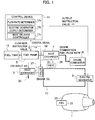
- a heat exhaust system of this embodiment shown in Fig. 1 is configured to release heat generated by an electric generator 3 that is installed in an aircraft and directly connected to a gas turbine engine 1 thereof.
- the heat exhaust system includes a fuel pump 5, two heat exchangers 7 and 9, and a control device 11.
- the fuel pump 5 is a variable-flow electric metering pump which supplies fuel in a fuel tank 13 to an engine combustor 15 of the gas turbine engine 1.
- the fuel pump 5 can perform variable control of flow rate of the fuel supplied from the fuel tank 13 to the engine combustor 15 so as not to supply excess fuel that exceeds a flow rate required for combustion in the engine combustor 15.
- the fuel pump 5 is driven by electric power generated by the electric generator 3. Specifically, the power to be transmitted from the gas turbine engine through the accessory gear box (AGB), which would serve as a power source for the conventional gear pump, is not used for driving the fuel pump 5.
- AGB accessory gear box
- the heat exchanger 7 is provided on a fuel supply passage 19 extending from the fuel tank 13 to the engine combustor 15.
- the engine oil at a flow rate corresponding to an opening degree of a valve 29 flows in from a circulation passage 17 and passes through the heat exchanger 7.
- the heat exchanger 7 adopts the fuel to be combusted in the engine combustor 15 as the heat-receiving medium, and performs the heat exchange between the fuel and the engine oil in the circulation passage 17 that flows in through the valve 29.
- a portion of the fuel supply passage 19 from the fuel tank 13 to the heat exchanger 7 indicated with a dashed line corresponds to a portion of passage of the low-temperature fuel before the heat generated by the electric generator 3 is released from the engine oil in the circulation passage 17.
- a portion of the fuel supply passage 19 from the heat exchanger 7 to the engine combustor 15 indicated with a solid line corresponds to a portion of passage of the high-temperature fuel after the heat generated by the electric generator 3 is released from the engine oil in the circulation passage 17.
- the heat exchanger 9 is provided on a flow passage 25 where at least part of the air taken by a fan 21 at an inlet of the gas turbine engine 1 into an engine case 23 flows.
- the engine oil at a flow rate corresponding to an opening degree of a valve 27, flows in from the circulation passage 17 and passes through the heat exchanger 9.
- the heat exchanger 9 adopts the air in the flow passage 25 as the heat-receiving medium, and performs the heat exchange between the air and the engine oil in the circulation passage 17, which flows in through the valve 27.
- a portion of the circulation passage 17 from the electric generator 3 to the heat exchanger 7, in terms of the direction of circulation of the engine oil which is indicated with a solid line, corresponds to a portion of passage of the high-temperature engine oil before releasing the heat generated by the electric generator 3.
- a portion of the circulation passage 17 from the heat exchanger 7 to the electric generator 3, in terms of the direction of circulation of the engine oil which is indicated with a dashed line, corresponds to a portion of passage of the low-temperature engine oil after releasing the heat generated by the electric generator 3.
- the control device 11 controls an output from the electric generator 3 based on an output instruction value and controls the flow rate of the fuel in the fuel tank 13, to be supplied to the engine combustor 15 with the fuel pump 5 based on a flow rate instruction value.
- the control device 11 may be an aircraft digital engine control device (FADEC: full authority digital engine control) for engine control that conducts control of the electric generator 3 at the same time.
- FADEC full authority digital engine control
- a combination of the FADEC device and a control device for the electric generator 3 may constitute the control device 11.
- the control device 11 is assumed to be the FADEC device, which conducts the control of the electric generator 3 at the same time.
- the control device 11 detects or determines the output from the electric generator 3 based on the output instruction value to be outputted to the electric generator 3, and detects or determines the flow rate of the fuel supplied from the fuel tank 13 to the engine combustor 15 based on the flow rate instruction value to be outputted to the fuel pump 5. Accordingly, the control device 11 functions as a fuel flow rate determiner 11a and as an electric generator output determiner 11b.
- the flow rate of the fuel supplied to the engine combustor 15 may be detected or determined by estimation from the instruction value on the number of revolutions of the pump or estimation from the actual number of revolutions of the pump measured at the fuel pump 5. Meanwhile, besides the estimation from the flow rate instruction value and the instruction value on the number of revolutions of the pump mentioned above, the flow rate of the fuel supplied from the fuel tank 13 to the engine combustor 15 may be detected or determined from measurement of the fuel flowing in the fuel supply passage 19 by using a sensor and the like. Besides the output instruction value mentioned above, the output from the electric generator 3 may be detected or determined, for example, from a measurement value by using a current sensor and the like.
- the control device 11 also functions as a heat release controller 11c that controls release of the heat generated by the electric generator 3 at the heat exchanger 7 and 9. There are three control patterns of heat release by the control device 11.
- the first is a pattern in which the control device 11 controls a distribution ratio between an amount of heat to be released into the fuel supplied to the engine combustor 15 and an amount of heat to be released into the air taken by the fan 21 into the engine case 23, and flowing in the flow passage 25 by using one or both of the output from the electric generator 3 and the flow rate of the fuel supplied to the engine combustor 15 as a control parameter (or parameters).
- the control device 11 adjusts the opening degree of the valve 27 such that the engine oil in the circulation passage 17 can release the amount of heat corresponding to the aforementioned distribution ratio into the air flowing in the flow passage 25, thereby controlling the flow rate of the engine oil flowing from the circulation passage 17 into the heat exchanger 9 at the flow rate in conformity to the aforementioned distribution ratio.
- control device 11 may adjust the opening degree of the valve 29 such that the amount of heat corresponding to the aforementioned distribution ratio is released from the engine oil in the circulation passage 17 into the fuel flowing in the fuel supply passage 19, thereby controlling the flow rate of the engine oil flowing from the circulation passage 17 into the heat exchanger 7 at the flow rate in conformity to the aforementioned distribution ratio.
- control device 11 can also adjust the opening degrees of both of the valves 29 and 27, respectively, thereby controlling the flow rates of the engine oil flowing into both of the heat exchangers 7 and 9 at the flow rates in conformity to the aforementioned distribution ratio.
- the second is a pattern in which the control device 11 controls the output instruction value to be outputted to the electric generator 3 by using the output from the electric generator 3 as a control parameter.
- the output from the electric generator 3 is controlled at the output corresponding to the amount of heat generation in conformity to the thermal capacity of the fuel, so that all the heat generated by the electric generator 3 can be released into the fuel supplied to the engine combustor 15 by the fuel pump 5 at the flow rate detected or determined by the control device 11 based on the flow rate instruction value.
- the third is a pattern in which the control device 11 controls the flow rate instruction value to be outputted to the fuel pump 5 by using the flow rate of the fuel supplied to the engine combustor 15 as a control parameter.
- the flow rate of the fuel supplied to the engine combustor 15 by the fuel pump 5 is controlled at the flow rate corresponding to the thermal capacity in conformity to the amount of heat generation by the electric generator 3, so that all the heat generated by the electric generator 3 at the output detected or determined by the control device 11, based on the output instruction value, can be released into the fuel supplied to the engine combustor 15.
- the opening degree of the valve 27 may be added as a controlled object, and the flow rate of the engine oil to release the heat into the air in the flow passage 25 by the heat exchange at the heat exchanger 9 may also be controlled in the third control pattern. It is effective to carry out this control as appropriate in the case where all the heat generated by the electric generator 3 may not be successfully released into the fuel supplied to the engine combustor 15.
- a heat exhaust system for an on-aircraft electric generator which supplies fuel to an engine combustor by using a gear pump, will be described with reference to an explanatory diagram of Fig. 2 for the purpose of comparison.
- a fuel pump 33 being a constant-volume gear pump supplies the fuel from the fuel tank 13 to the engine combustor 15.
- the fuel pump 33 is driven together with an electric generator 4 by an accessory gear box 2 (AGB) disposed in the vicinity of the engine case 23. Accordingly, the flow rate of the fuel discharged from the fuel pump 33 varies with a change in the number of revolutions of the AGB 2 that depends on the output from the gas turbine engine 1.
- AGB accessory gear box 2
- a heat exchanger 39 provided on the back-flow passage 37 to return the excess fuel to the fuel tank 13 also releases the heat generated by the electric generator 4 from the engine oil into the fuel in the back-flow passage 37 in the heat exhaust system of Fig. 2 .
- the increase in the amount of heat release into the air in the flow passage 25 is likely to cause reduction in air pressure at an outlet of the fan 21, or reduction in flow rate of the air at the outlet of the fan 21. Accordingly, there is a limit for increasing the amount of heat release at the heat exchanger 9. In the meantime, the heat release into the excess fuel in the back-flow passage 37 causes the high-temperature fuel to flow into the fuel tank 13, and may therefore be prohibited due to a safety reason when there is only a small amount of fuel left in the fuel tank 13, for instance.
- the heat exhaust system of Fig. 2 installed in the aircraft for supplying the fuel to the engine combustor 15 by using the fuel pump 33 being the gear pump, may potentially cause a failure to release all of the heat generated by the electric generator 4.
- a heat exhaust control device 41 which is different from the control device 11 that outputs the flow rate instruction value to the fuel control unit 35, will take on a role for detecting respective temperatures of the fuel supplied to the engine combustor 15 and of the engine oil in the circulation passage 17 to be involved in the heat exchange at the heat exchanger 7, and for controlling an opening action and/or the opening degree of the valve 27 based on the detected temperatures.
- the heat exhaust system of Fig. 2 has difficulty in conducting integrative and detailed control of the amount of heat generation by the electric generator 4 and the amounts of heat release at the respective heat exchangers 7 and 9.
- a rise in temperature of the fuel supplied to the engine combustor 15 is alleviated by adopting the fuel to be combusted in the engine combustor 15 and/or the air at the outlet of the fan 21 as the heat-receiving media, and employing the fuel pump 5 that can control the flow rate of the fuel supplied to the engine combustor 15.
- the fuel pump 5 that can control the flow rate of the fuel supplied to the engine combustor 15.
- the heat exhaust system of the embodiment shown in Fig. 1 can properly release the heat generated by the electric generator 3 without the need to adopt the excess fuel as the heat-receiving medium, which is supposed to be returned from the fuel control unit 35 to the inlet of the fuel pump 33 or the fuel tank 13 through the back-flow passage 37 as in the heat exhaust system of Fig. 2 .
- the heat exchanger 9 to be provided on the flow passage 25 to allow passage of the intake air does not have to be increased in size. For this reason, it is possible to avoid deterioration in output efficiency of the gas turbine engine 1, which would be caused by disposing the large heat exchanger 9 in the engine case 23.
- the distribution ratio between the amount of heat to be released into the fuel supplied to the engine combustor 15, and the amount of heat to be released into the air taken by the fan 21 into the engine case 23 and flowing in the flow passage 25 is determined based on at least one of the output instruction value to the electric generator 3 corresponding to the amount of heat generation by the electric generator 3 and the flow rate instruction value to the fuel pump 5 corresponding to the thermal capacity of the fuel supplied to the engine combustor 15.
- the opening action and/or the opening degree of the valve 27 to adjust the amount of the engine oil to flow into the heat exchanger 9 on the flow passage 25 for the air taken by the fan 21 into the engine case 23 is decided by the distribution ratio thus determined.
- the output instruction value to the electric generator 3 corresponding to the amount of heat generation by the electric generator 3 may be determined depending on the flow rate instruction value to the fuel pump 5 corresponding to the thermal capacity of the fuel supplied to the engine combustor 15, and details of the control involving the opening action and/or the opening degree of the valve 27 corresponding to the amount of heat release by the heat exchanger 9 may also be decided.
- the flow rate of the engine oil flowing in from the circulation passage 17 and passing through the heat exchanger 7 may be controlled by the control device 11 in accordance with the opening degree of the valve 29 in the third control pattern, which is designed for the control device 11 to control the flow rate instruction value to be outputted to the fuel pump 5 by using the flow rate of the fuel supplied to the engine combustor 15 as the control parameter.
- the opening degrees of the valves 29 and 27 of the heat exchangers 7 and 9 may be controlled by the control device 11, respectively.
- the opening degrees of the respective valves 29 and 27 it is possible to adjust the distribution ratio between the heat from the electric generator 3 to be released from the engine oil in the circulation passage 17 into the fuel supplied to the engine combustor 15 at the heat exchanger 7, and the heat from the electric generator 3 to be released from the engine oil in the circulation passage 17 into the air at the heat exchanger 9.
- a measurement value obtained by directly measuring the output from the electric generator 3 may be fed back to the control device 11 so as to cause the control device 11 to control the output instruction value to be outputted to the electric generator 3 in the second pattern, which is designed for the control device 11 to control the output instruction value to be outputted to the electric generator 3 by using the output from the electric generator 3 as the control parameter.
- the heat exhaust system for an on-aircraft electric generator includes: a fuel pump which is driven by electric power generated by an electric generator installed in an aircraft and is configured to measure and supply fuel to an engine of the aircraft; a first heat exchanger configured to release heat generated by the electric generator into the fuel supplied to the engine; a fuel flow rate determiner configured to determine a flow rate of the fuel supplied to the engine by the fuel pump; an electric generator output determiner configured to determine an output from the electric generator; and a heat release controller configured to control heat release at the first heat exchanger by using at least one of the flow rate of the fuel determined by the fuel flow rate determiner and the output determined by the electric generator output determiner as a control parameter.
- the fuel pump measures and supplies the fuel to the engine, and thus eliminates the possibility of discharging fuel in an amount exceeding the amount required by the engine combustor, as in the case of the gear pump driven by the gear box in the related art. For this reason, it is no longer necessary to return the excess fuel to the inlet of the gear pump or the fuel tank.
- the heat release controller controls the heat release at the first heat exchanger by using at least one of the flow rate of the fuel supplied to the engine which is determined by the fuel flow rate determiner and the output from the electric generator which is determined by the electric generator output determiner as the control parameter.
- a single control device may constitute the fuel flow rate determiner, the electric generator output determiner, and the heat release controller.
- the fuel flow rate determiner the electric generator output determiner
- the heat release controller the heat release controller
- the heat release controller can also control the output from the electric generator by using the output determined by the electric generator output determiner as the control parameter.
- the heat release controller may control the flow rate of the fuel supplied to the engine by the electric metering pump by using the flow rate of the fuel determined by the fuel flow rate determiner as the control parameter.
- the flow rate of the fuel supplied to the engine by the fuel pump can be controlled by the heat release controller such that the thermal capacity of the fuel supplied to the engine becomes equivalent to the heat from the electric generator to be released at the first heat exchanger.
- the heat generated by the electric generator can be properly released.
- the heat exhaust system may further include a second heat exchanger which releases the heat generated by the electric generator into air that is taken by a fan into a case of the engine, and the heat release controller may control heat release at the second heat exchanger.
- the heat exhaust system may further include a valve which adjusts an amount of introduction of the heat generated by the electric generator into any of the first and second heat exchangers.
- the heat release controller may adjust an opening degree of this valve.
- a heat exhaust system is broadly applicable to aircraft equipped with an electric generator.
Landscapes
- Engineering & Computer Science (AREA)
- Chemical & Material Sciences (AREA)
- Combustion & Propulsion (AREA)
- Mechanical Engineering (AREA)
- General Engineering & Computer Science (AREA)
- Aviation & Aerospace Engineering (AREA)
- Engine Equipment That Uses Special Cycles (AREA)
- Control Of Eletrric Generators (AREA)
Abstract
Description
- This disclosure relates to a heat exhaust system for an on-aircraft electric generator.
- An electric generator to generate electric power to be supplied to electric equipment is installed in an aircraft. The electric generator is driven by power transmitted from a gas turbine engine through an accessory gear box for driving auxiliary machines. The heat generating electric generator is cooled by engine oil, and the heat of the engine oil is released at a heat exchanger into fuel supplied from a fuel tank to the gas turbine engine, into air at an outlet of a fan of the gas turbine engine, and the like.
Patent Literature 1 discloses a technique related thereto. - Meanwhile, various equipment installed in aircraft have been converted to be electric in recent years. Such conversion can be observed, for example, in a fuel pump for supplying fuel from a fuel tank to a gas turbine engine. A general fuel pump is a gear pump that is driven by power transmitted from a gas turbine engine through an accessory gear box.
- A flow rate of the fuel discharged from the gear pump depends on the number of revolutions of the gas turbine engine that supplies the power through the accessory gear box. As a consequence, there may be a case in which the gear pump discharges fuel in an amount exceeding that required by a combustor of the gas turbine engine, and the excess fuel has to be returned to an inlet of the gear pump, the fuel tank, and the like.
- In this regard, the applicant of this disclosure has previously proposed a technique for enabling control of the number of revolutions of a gear pump without dependence on the number of revolutions of an engine but instead by rotating the gear pump with a dedicated electric motor. According to this proposal, by regulating the number of revolutions of the gear pump with the electric motor, it is possible to control the flow rate of the fuel to be discharged from the gear pump to an amount required for combustion by the combustor. Patent Literature 2 discloses the related technique.
-
- Patent Literature 1: Japanese Patent No.
5384670 - Patent Literature 2: Japanese Patent Application Publication No.
2013-231406 - As the equipment installed in the aircraft including the above-mentioned gear pump are increasingly electrified, the aircraft will need to carry a large-size electric generator with a higher power generation capacity. An increase in size of the electric generator results in a larger amount of heat generation by the electric generator. Accordingly, an amount of heat to be released into the fuel, the air at the outlet of the fan, and the like by the intermediary of the engine oil is increased as well.
- In the meantime, the fuel supplied to the gas turbine engine is on the decrease thanks to an improvement in fuel efficiency of the gas turbine engine. Reduction in fuel supply to the gas turbine engine decreases a thermal capacity per unit time of the supplied fuel that serves as a coolant. Accordingly, in view of further improvements in fuel efficiency of the gas turbine engines in the future, it will be difficult to count on the fuel supplied to the gas turbine engine to serve as a destination of heat release for the additional heat attributed to the larger amount of heat generation of the electric generator increased in size.
- An object of this disclosure is to provide a heat exhaust system for an on-aircraft electric generator, which is capable of properly releasing heat generated by an electric generator installed in an aircraft.
- An aspect of this disclosure provides a heat exhaust system for an on-aircraft electric generator, including: a fuel pump driven by electric power generated by an electric generator installed in an aircraft and configured to measure and supply fuel to an engine of the aircraft; a first heat exchanger configured to release heat generated by the electric generator into the fuel supplied to the engine; a fuel flow rate determiner configured to determine a flow rate of the fuel supplied to the engine by the fuel pump; an electric generator output determiner configured to determine an output from the electric generator; and a heat release controller configured to control heat release at the first heat exchanger by using at least one of the flow rate of the fuel determined by the fuel flow rate determiner and the output determined by the electric generator output determiner as a control parameter.
-
-
Fig. 1 is an explanatory diagram showing a heat exhaust system for an on-aircraft electric generator according to an embodiment of this disclosure. -
Fig. 2 is an explanatory diagram showing a heat exhaust system for an electric generator installed in an aircraft that supplies fuel to an engine combustor by using a gear pump. - An embodiment of this disclosure will be described below with reference to a drawing.
- A heat exhaust system of this embodiment shown in
Fig. 1 is configured to release heat generated by an electric generator 3 that is installed in an aircraft and directly connected to agas turbine engine 1 thereof. The heat exhaust system includes afuel pump 5, twoheat exchangers 7 and 9, and acontrol device 11. - The
fuel pump 5 is a variable-flow electric metering pump which supplies fuel in afuel tank 13 to anengine combustor 15 of thegas turbine engine 1. Thefuel pump 5 can perform variable control of flow rate of the fuel supplied from thefuel tank 13 to theengine combustor 15 so as not to supply excess fuel that exceeds a flow rate required for combustion in theengine combustor 15. - Unlike the gear pump that has conventionally been used as a metering pump, the
fuel pump 5 is driven by electric power generated by the electric generator 3. Specifically, the power to be transmitted from the gas turbine engine through the accessory gear box (AGB), which would serve as a power source for the conventional gear pump, is not used for driving thefuel pump 5. - The heat generated by the electric generator 3, which an engine oil for lubrication in the
gas turbine engine 1 receives from the electric generator 3, is subjected to heat exchange by the twoheat exchangers 7 and 9, and is released into a heat-receiving medium on a low-temperature side. - The
heat exchanger 7 is provided on afuel supply passage 19 extending from thefuel tank 13 to theengine combustor 15. The engine oil at a flow rate corresponding to an opening degree of avalve 29 flows in from acirculation passage 17 and passes through theheat exchanger 7. Theheat exchanger 7 adopts the fuel to be combusted in theengine combustor 15 as the heat-receiving medium, and performs the heat exchange between the fuel and the engine oil in thecirculation passage 17 that flows in through thevalve 29. - Here, a portion of the
fuel supply passage 19 from thefuel tank 13 to theheat exchanger 7 indicated with a dashed line corresponds to a portion of passage of the low-temperature fuel before the heat generated by the electric generator 3 is released from the engine oil in thecirculation passage 17. Meanwhile, a portion of thefuel supply passage 19 from theheat exchanger 7 to theengine combustor 15 indicated with a solid line corresponds to a portion of passage of the high-temperature fuel after the heat generated by the electric generator 3 is released from the engine oil in thecirculation passage 17. - On the other hand, the heat exchanger 9 is provided on a
flow passage 25 where at least part of the air taken by afan 21 at an inlet of thegas turbine engine 1 into anengine case 23 flows. The engine oil, at a flow rate corresponding to an opening degree of avalve 27, flows in from thecirculation passage 17 and passes through the heat exchanger 9. - On a portion of the
circulation passage 17 located upstream of theheat exchanger 7, in terms of a direction of circulation of the engine oil, the heat exchanger 9 adopts the air in theflow passage 25 as the heat-receiving medium, and performs the heat exchange between the air and the engine oil in thecirculation passage 17, which flows in through thevalve 27. - Here, a portion of the
circulation passage 17 from the electric generator 3 to theheat exchanger 7, in terms of the direction of circulation of the engine oil which is indicated with a solid line, corresponds to a portion of passage of the high-temperature engine oil before releasing the heat generated by the electric generator 3. Meanwhile, a portion of thecirculation passage 17 from theheat exchanger 7 to the electric generator 3, in terms of the direction of circulation of the engine oil which is indicated with a dashed line, corresponds to a portion of passage of the low-temperature engine oil after releasing the heat generated by the electric generator 3. - The
control device 11 controls an output from the electric generator 3 based on an output instruction value and controls the flow rate of the fuel in thefuel tank 13, to be supplied to theengine combustor 15 with thefuel pump 5 based on a flow rate instruction value. Thecontrol device 11 may be an aircraft digital engine control device (FADEC: full authority digital engine control) for engine control that conducts control of the electric generator 3 at the same time. Alternatively, a combination of the FADEC device and a control device for the electric generator 3 may constitute thecontrol device 11. In the following description, thecontrol device 11 is assumed to be the FADEC device, which conducts the control of the electric generator 3 at the same time. - The
control device 11 detects or determines the output from the electric generator 3 based on the output instruction value to be outputted to the electric generator 3, and detects or determines the flow rate of the fuel supplied from thefuel tank 13 to theengine combustor 15 based on the flow rate instruction value to be outputted to thefuel pump 5. Accordingly, thecontrol device 11 functions as a fuel flow rate determiner 11a and as an electric generator output determiner 11b. - Here, when the
control device 11 outputs an instruction value on the number of revolutions of the pump to thefuel pump 5 instead of outputting the flow rate instruction value, the flow rate of the fuel supplied to theengine combustor 15 may be detected or determined by estimation from the instruction value on the number of revolutions of the pump or estimation from the actual number of revolutions of the pump measured at thefuel pump 5. Meanwhile, besides the estimation from the flow rate instruction value and the instruction value on the number of revolutions of the pump mentioned above, the flow rate of the fuel supplied from thefuel tank 13 to theengine combustor 15 may be detected or determined from measurement of the fuel flowing in thefuel supply passage 19 by using a sensor and the like. Besides the output instruction value mentioned above, the output from the electric generator 3 may be detected or determined, for example, from a measurement value by using a current sensor and the like. - The
control device 11 also functions as aheat release controller 11c that controls release of the heat generated by the electric generator 3 at theheat exchanger 7 and 9. There are three control patterns of heat release by thecontrol device 11. - The first is a pattern in which the
control device 11 controls a distribution ratio between an amount of heat to be released into the fuel supplied to theengine combustor 15 and an amount of heat to be released into the air taken by thefan 21 into theengine case 23, and flowing in theflow passage 25 by using one or both of the output from the electric generator 3 and the flow rate of the fuel supplied to theengine combustor 15 as a control parameter (or parameters). According to this pattern, thecontrol device 11 adjusts the opening degree of thevalve 27 such that the engine oil in thecirculation passage 17 can release the amount of heat corresponding to the aforementioned distribution ratio into the air flowing in theflow passage 25, thereby controlling the flow rate of the engine oil flowing from thecirculation passage 17 into the heat exchanger 9 at the flow rate in conformity to the aforementioned distribution ratio. - Here, the
control device 11 may adjust the opening degree of thevalve 29 such that the amount of heat corresponding to the aforementioned distribution ratio is released from the engine oil in thecirculation passage 17 into the fuel flowing in thefuel supply passage 19, thereby controlling the flow rate of the engine oil flowing from thecirculation passage 17 into theheat exchanger 7 at the flow rate in conformity to the aforementioned distribution ratio. Meanwhile, thecontrol device 11 can also adjust the opening degrees of both of thevalves heat exchangers 7 and 9 at the flow rates in conformity to the aforementioned distribution ratio. - The second is a pattern in which the
control device 11 controls the output instruction value to be outputted to the electric generator 3 by using the output from the electric generator 3 as a control parameter. According to this pattern, the output from the electric generator 3 is controlled at the output corresponding to the amount of heat generation in conformity to the thermal capacity of the fuel, so that all the heat generated by the electric generator 3 can be released into the fuel supplied to theengine combustor 15 by thefuel pump 5 at the flow rate detected or determined by thecontrol device 11 based on the flow rate instruction value. - The third is a pattern in which the
control device 11 controls the flow rate instruction value to be outputted to thefuel pump 5 by using the flow rate of the fuel supplied to theengine combustor 15 as a control parameter. According to this pattern, the flow rate of the fuel supplied to theengine combustor 15 by thefuel pump 5 is controlled at the flow rate corresponding to the thermal capacity in conformity to the amount of heat generation by the electric generator 3, so that all the heat generated by the electric generator 3 at the output detected or determined by thecontrol device 11, based on the output instruction value, can be released into the fuel supplied to theengine combustor 15. - Note that the opening degree of the
valve 27 may be added as a controlled object, and the flow rate of the engine oil to release the heat into the air in theflow passage 25 by the heat exchange at the heat exchanger 9 may also be controlled in the third control pattern. It is effective to carry out this control as appropriate in the case where all the heat generated by the electric generator 3 may not be successfully released into the fuel supplied to theengine combustor 15. - Here, a heat exhaust system for an on-aircraft electric generator, which supplies fuel to an engine combustor by using a gear pump, will be described with reference to an explanatory diagram of
Fig. 2 for the purpose of comparison. In the heat exhaust system shown inFig. 2 , afuel pump 33 being a constant-volume gear pump supplies the fuel from thefuel tank 13 to theengine combustor 15. - The
fuel pump 33 is driven together with anelectric generator 4 by an accessory gear box 2 (AGB) disposed in the vicinity of theengine case 23. Accordingly, the flow rate of the fuel discharged from thefuel pump 33 varies with a change in the number of revolutions of the AGB 2 that depends on the output from thegas turbine engine 1. - In this heat exhaust system, there may occur a case in which the
fuel pump 33 discharges the excess fuel that exceeds the required flow rate for combustion in theengine combustor 15. When such a case occurs, the excess fuel is separated from the fuel to be supplied to theengine combustor 15 by afuel control unit 35, and is returned to an inlet of thefuel pump 33 through a back-flow passage 37. In the meantime, part of the fuel in the back-flow passage 37 may also be returned to thefuel tank 13. - Accordingly, in addition to the
heat exchangers 7 and 9, aheat exchanger 39 provided on the back-flow passage 37 to return the excess fuel to thefuel tank 13 also releases the heat generated by theelectric generator 4 from the engine oil into the fuel in the back-flow passage 37 in the heat exhaust system ofFig. 2 . - However, in the heat exhaust system of
Fig. 2 , the excess fuel is flowed back to thefuel tank 13 or the inlet of thefuel pump 33. As a consequence, the fuel that is heated to a high temperature after passing through thefuel pump 33, being the gear pump, many times is supplied to theengine combustor 15. For this reason, the thermal capacity of the fuel flowing into theheat exchanger 7 is reduced, and the amount of heat release at theheat exchanger 7 is decreased. In order to make up for this decrease, it is necessary to increase the amount of heat release into the air in theflow passage 25 at the heat exchanger 9, or the amount of heat release into the excess fuel in the back-flow passage 37 at theheat exchanger 39. - Nonetheless, the increase in the amount of heat release into the air in the
flow passage 25 is likely to cause reduction in air pressure at an outlet of thefan 21, or reduction in flow rate of the air at the outlet of thefan 21. Accordingly, there is a limit for increasing the amount of heat release at the heat exchanger 9. In the meantime, the heat release into the excess fuel in the back-flow passage 37 causes the high-temperature fuel to flow into thefuel tank 13, and may therefore be prohibited due to a safety reason when there is only a small amount of fuel left in thefuel tank 13, for instance. - From the above-mentioned circumstances, the heat exhaust system of
Fig. 2 , installed in the aircraft for supplying the fuel to theengine combustor 15 by using thefuel pump 33 being the gear pump, may potentially cause a failure to release all of the heat generated by theelectric generator 4. - However, even if such a situation takes place, the
control device 11 cannot grasp the amount of heat generation by theelectric generator 4 from an operating condition of theelectric generator 4 because a control system of theelectric generator 4 is completely independent from thecontrol device 11 or the FADEC device constituting thecontrol device 11. As a consequence, a heatexhaust control device 41, which is different from thecontrol device 11 that outputs the flow rate instruction value to thefuel control unit 35, will take on a role for detecting respective temperatures of the fuel supplied to theengine combustor 15 and of the engine oil in thecirculation passage 17 to be involved in the heat exchange at theheat exchanger 7, and for controlling an opening action and/or the opening degree of thevalve 27 based on the detected temperatures. - Therefore, the heat exhaust system of
Fig. 2 has difficulty in conducting integrative and detailed control of the amount of heat generation by theelectric generator 4 and the amounts of heat release at therespective heat exchangers 7 and 9. - On the other hand, according to the heat exhaust system of the embodiment shown in
Fig. 1 , a rise in temperature of the fuel supplied to theengine combustor 15 is alleviated by adopting the fuel to be combusted in theengine combustor 15 and/or the air at the outlet of thefan 21 as the heat-receiving media, and employing thefuel pump 5 that can control the flow rate of the fuel supplied to theengine combustor 15. Thus, it is possible to impart a larger thermal capacity to the fuel serving as the heat-receiving medium for the heat release. Meanwhile, the fuel used for the heat release is combusted in theengine combustor 15 without being flowed back to thefuel tank 13 and the like. In this regard, the rise in temperature of the fuel due to the heat release does not cause any problem. - For this reason, the heat exhaust system of the embodiment shown in
Fig. 1 can properly release the heat generated by the electric generator 3 without the need to adopt the excess fuel as the heat-receiving medium, which is supposed to be returned from thefuel control unit 35 to the inlet of thefuel pump 33 or thefuel tank 13 through the back-flow passage 37 as in the heat exhaust system ofFig. 2 . - Furthermore, it is not necessary to release all of the heat generated by the electric generator 3 into the air taken by the
fan 21 and taken into theengine case 23. Accordingly, the heat exchanger 9 to be provided on theflow passage 25 to allow passage of the intake air does not have to be increased in size. For this reason, it is possible to avoid deterioration in output efficiency of thegas turbine engine 1, which would be caused by disposing the large heat exchanger 9 in theengine case 23. - Meanwhile, according to the heat exhaust system of this embodiment, the distribution ratio between the amount of heat to be released into the fuel supplied to the
engine combustor 15, and the amount of heat to be released into the air taken by thefan 21 into theengine case 23 and flowing in theflow passage 25 is determined based on at least one of the output instruction value to the electric generator 3 corresponding to the amount of heat generation by the electric generator 3 and the flow rate instruction value to thefuel pump 5 corresponding to the thermal capacity of the fuel supplied to theengine combustor 15. - Then, the opening action and/or the opening degree of the
valve 27 to adjust the amount of the engine oil to flow into the heat exchanger 9 on theflow passage 25 for the air taken by thefan 21 into theengine case 23 is decided by the distribution ratio thus determined. - On the other hand, the output instruction value to the electric generator 3 corresponding to the amount of heat generation by the electric generator 3 may be determined depending on the flow rate instruction value to the
fuel pump 5 corresponding to the thermal capacity of the fuel supplied to theengine combustor 15, and details of the control involving the opening action and/or the opening degree of thevalve 27 corresponding to the amount of heat release by the heat exchanger 9 may also be decided. - As a consequence, it is possible to conduct the control of the electric generator 3 based on the output of the output instruction value and the control of the opening action and/or the opening degree of the
valve 27 of the heat exchanger 9 at the same time by thecontrol device 11 that controls thefuel pump 5 based on the output of the flow rate instruction value. In this way, the configuration of the control system can be simplified, and an increase in burden owing to cooperation with other control devices can be thus prevented. - Here, among the above-described control patterns of heat release by the
control device 11, the flow rate of the engine oil flowing in from thecirculation passage 17 and passing through theheat exchanger 7 may be controlled by thecontrol device 11 in accordance with the opening degree of thevalve 29 in the third control pattern, which is designed for thecontrol device 11 to control the flow rate instruction value to be outputted to thefuel pump 5 by using the flow rate of the fuel supplied to theengine combustor 15 as the control parameter. - In this case, the opening degrees of the
valves heat exchangers 7 and 9 may be controlled by thecontrol device 11, respectively. By adjusting the opening degrees of therespective valves circulation passage 17 into the fuel supplied to theengine combustor 15 at theheat exchanger 7, and the heat from the electric generator 3 to be released from the engine oil in thecirculation passage 17 into the air at the heat exchanger 9. - Meanwhile, among the control patterns of heat release by the
control device 11, a measurement value obtained by directly measuring the output from the electric generator 3 may be fed back to thecontrol device 11 so as to cause thecontrol device 11 to control the output instruction value to be outputted to the electric generator 3 in the second pattern, which is designed for thecontrol device 11 to control the output instruction value to be outputted to the electric generator 3 by using the output from the electric generator 3 as the control parameter. - As described above, the heat exhaust system for an on-aircraft electric generator according to the aspect of this disclosure includes: a fuel pump which is driven by electric power generated by an electric generator installed in an aircraft and is configured to measure and supply fuel to an engine of the aircraft; a first heat exchanger configured to release heat generated by the electric generator into the fuel supplied to the engine; a fuel flow rate determiner configured to determine a flow rate of the fuel supplied to the engine by the fuel pump; an electric generator output determiner configured to determine an output from the electric generator; and a heat release controller configured to control heat release at the first heat exchanger by using at least one of the flow rate of the fuel determined by the fuel flow rate determiner and the output determined by the electric generator output determiner as a control parameter.
- In the above-described heat exhaust system, the fuel pump measures and supplies the fuel to the engine, and thus eliminates the possibility of discharging fuel in an amount exceeding the amount required by the engine combustor, as in the case of the gear pump driven by the gear box in the related art. For this reason, it is no longer necessary to return the excess fuel to the inlet of the gear pump or the fuel tank.
- As a consequence, a situation in which the fuel supplied to the engine repeatedly passes through the gear pump and is thus heated to a high temperature due to the circulation of the excess fuel to the inlet of the gear pump or the fuel tank is less likely to occur. Thus, it is possible to impart a sufficient thermal capacity as the heat-receiving medium to the fuel that flows from the fuel pump into the first heat exchanger and is supplied to the engine.
- Meanwhile, in the above-described heat exhaust system, the heat release controller controls the heat release at the first heat exchanger by using at least one of the flow rate of the fuel supplied to the engine which is determined by the fuel flow rate determiner and the output from the electric generator which is determined by the electric generator output determiner as the control parameter. Thus, it is possible to properly release the heat generated by the electric generator while striking a balance between the heat generation corresponding to the output from the electric generator and the thermal capacity corresponding to the flow rate of the fuel supplied to the engine without expectation of the heat release into the excess fuel to be returned to the fuel tank.
- In the above-described heat exhaust system, a single control device may constitute the fuel flow rate determiner, the electric generator output determiner, and the heat release controller. Thus, it is possible to conduct integrative and detailed control of the amount of heat generation by the electric generator and/or the amounts of heat release by the respective heat exchangers.
- Meanwhile, the heat release controller can also control the output from the electric generator by using the output determined by the electric generator output determiner as the control parameter.
- Thus, it is possible to properly release the heat generated by the electric generator while controlling the output from the electric generator with the heat release controller such that the heat from the electric generator to be released at the first heat exchanger becomes equivalent to the thermal capacity of the fuel supplied to the engine.
- Here, the heat release controller may control the flow rate of the fuel supplied to the engine by the electric metering pump by using the flow rate of the fuel determined by the fuel flow rate determiner as the control parameter.
- In this case, the flow rate of the fuel supplied to the engine by the fuel pump can be controlled by the heat release controller such that the thermal capacity of the fuel supplied to the engine becomes equivalent to the heat from the electric generator to be released at the first heat exchanger. Thus, the heat generated by the electric generator can be properly released.
- Meanwhile, the heat exhaust system may further include a second heat exchanger which releases the heat generated by the electric generator into air that is taken by a fan into a case of the engine, and the heat release controller may control heat release at the second heat exchanger.
- Thus, it is possible to properly release the heat generated by the electric generator while arranging so that the heat from the electric generator is also released into the air taken by the fan into the case of the engine.
- In the meantime, the heat exhaust system may further include a valve which adjusts an amount of introduction of the heat generated by the electric generator into any of the first and second heat exchangers. Here, the heat release controller may adjust an opening degree of this valve.
- It is possible to properly release the heat generated by the electric generator by setting the amount of heat release into the fuel supplied to the engine and/or the air taken into the case of the engine to the amount equivalent to the heat from the electric generator to be released at the respective heat exchangers.
- Although a certain embodiment of this disclosure has been described above, it is to be understood that this embodiment is merely an example described for facilitating understanding of the invention. The technical scope of this disclosure is not limited only to the specific technical matters disclosed in the embodiment, but also encompasses various modifications, changes, alternative technologies, and so forth that can be easily derived therefrom.
- This application claims the benefit of priority based on Japanese Patent Application No.
2016-170772 filed on Sep. 1, 2016 - A heat exhaust system, according to an aspect of this disclosure, is broadly applicable to aircraft equipped with an electric generator.
-
- 1 gas turbine engine (engine)
- 2 accessory gear box (AGB)
- 3 electric generator
- 4 electric generator
- 5 fuel pump
- 7, 9 heat exchanger (first heat exchanger, second heat exchanger)
- 11 control device (flow rate determiner, electric generator output determiner, heat release controller)
- 13 fuel tank
- 15 engine combustor
- 17 circulation passage
- 19 fuel supply passage
- 21 fan
- 23 engine case (case)
- 25 flow passage
- 27,29 valve
- 33 fuel pump
- 35 fuel control unit
- 37 back-flow passage
- 39 heat exchanger
- 41 heat exhaust control device
Claims (8)
- A heat exhaust system for an on-aircraft electric generator, comprising:a fuel pump driven by electric power generated by an electric generator installed in an aircraft, the fuel pump configured to measure and supply fuel to an engine of the aircraft;a first heat exchanger configured to release heat generated by the electric generator into the fuel supplied to the engine;a fuel flow rate determiner configured to determine a flow rate of the fuel supplied to the engine by the fuel pump;an electric generator output determiner configured to determine an output from the electric generator; anda heat release controller configured to control heat release at the first heat exchanger by using at least one of the flow rate of the fuel determined by the fuel flow rate determiner and the output determined by the electric generator output determiner as a control parameter.
- The heat exhaust system for an on-aircraft electric generator according to claim 1, wherein a single control device constitutes the fuel flow rate determiner, the electric generator output determiner, and the heat release controller.
- The heat exhaust system for an on-aircraft electric generator according to claim 1, wherein the heat release controller is configured to control the output from the electric generator by using the output determined by the electric generator output determiner as the control parameter.
- The heat exhaust system for an on-aircraft electric generator according to claim 1, further comprising:a second heat exchanger configured to release the heat generated by the electric generator into air which is taken by a fan into a case of the engine, whereinthe heat release controller is configured to control heat release at the second heat exchanger.
- The heat exhaust system for an on-aircraft electric generator according to claim 4, further comprising:a valve configured to adjust an amount of introduction of the heat generated by the electric generator into the first heat exchanger or the second heat exchanger, whereinthe heat release controller is configured to adjust an opening degree of the valve.
- The heat exhaust system for an on-aircraft electric generator according to claim 2, wherein the heat release controller is configured to control the output from the electric generator by using the output determined by the electric generator output determiner as the control parameter.
- The heat exhaust system for an on-aircraft electric generator according to claim 2, further comprising:a second heat exchanger configured to release the heat generated by the electric generator into air which is taken by a fan into a case of the engine, whereinthe heat release controller is configured to control heat release at the second heat exchanger.
- The heat exhaust system for an on-aircraft electric generator according to claim 7, further comprising:a valve configured to adjust an amount of introduction of the heat generated by the electric generator into the first heat exchanger or the second heat exchanger, whereinthe heat release controller is configured to adjust an opening degree of the valve.
Applications Claiming Priority (2)
| Application Number | Priority Date | Filing Date | Title |
|---|---|---|---|
| JP2016170772 | 2016-09-01 | ||
| PCT/JP2017/005398 WO2018042703A1 (en) | 2016-09-01 | 2017-02-15 | Heat exhaust system for on-aircraft electric generator |
Publications (3)
| Publication Number | Publication Date |
|---|---|
| EP3486457A1 true EP3486457A1 (en) | 2019-05-22 |
| EP3486457A4 EP3486457A4 (en) | 2020-03-25 |
| EP3486457B1 EP3486457B1 (en) | 2021-04-07 |
Family
ID=61301464
Family Applications (1)
| Application Number | Title | Priority Date | Filing Date |
|---|---|---|---|
| EP17845714.9A Active EP3486457B1 (en) | 2016-09-01 | 2017-02-15 | Heat exhaust system for on-aircraft electric generator |
Country Status (4)
| Country | Link |
|---|---|
| US (1) | US10914236B2 (en) |
| EP (1) | EP3486457B1 (en) |
| JP (1) | JP6587035B2 (en) |
| WO (1) | WO2018042703A1 (en) |
Families Citing this family (15)
| Publication number | Priority date | Publication date | Assignee | Title |
|---|---|---|---|---|
| US11466621B2 (en) * | 2019-03-20 | 2022-10-11 | Raytheon Technologies Corporation | Adaptive thermal management system for aircraft fuel system |
| IT201900005586A1 (en) * | 2019-04-11 | 2019-04-11 | ||
| GB201916566D0 (en) * | 2019-11-14 | 2020-01-01 | Rolls Royce Plc | Aircraft power generation system |
| EP4086176B1 (en) * | 2021-05-07 | 2025-03-05 | Airbus SAS | Electric propulsion unit of an aircraft comprising a cooling system incorporating at least one front air inlet and aircraft comprising at least one such electric propulsion unit |
| US20220381186A1 (en) * | 2021-05-26 | 2022-12-01 | Pratt & Whitney Canada Corp. | Heat exchange system for aircraft engine |
| FR3135297B1 (en) * | 2022-05-05 | 2024-07-05 | Safran Aircraft Engines | Turbomachine with heat exchanger between a fuel circuit and two lubricant circuits |
| EP4559813A1 (en) * | 2022-07-21 | 2025-05-28 | IHI Corporation | Aircraft hybrid motive power source system and method for controlling same |
| GB2622214A (en) | 2022-09-06 | 2024-03-13 | Rolls Royce Plc | A thermal management system for an aircraft |
| GB2622209B (en) | 2022-09-06 | 2024-12-04 | Rolls Royce Plc | A thermal management system for an aircraft |
| GB2622215B (en) * | 2022-09-06 | 2024-12-04 | Rolls Royce Plc | A thermal management system for an aircraft |
| GB2622211A (en) | 2022-09-06 | 2024-03-13 | Rolls Royce Plc | A thermal management system for an aircraft |
| GB2622208A (en) | 2022-09-06 | 2024-03-13 | Rolls Royce Plc | A thermal management system for an aircraft |
| GB2622299B (en) * | 2022-09-06 | 2024-10-02 | Rolls Royce Plc | A thermal management system for an aircraft |
| GB2622213B (en) | 2022-09-06 | 2024-12-18 | Rolls Royce Plc | A thermal management system for an aircraft |
| GB2622212B (en) | 2022-09-06 | 2024-11-20 | Rolls Royce Plc | A thermal management system for an aircraft |
Family Cites Families (16)
| Publication number | Priority date | Publication date | Assignee | Title |
|---|---|---|---|---|
| US4773212A (en) | 1981-04-01 | 1988-09-27 | United Technologies Corporation | Balancing the heat flow between components associated with a gas turbine engine |
| US4696156A (en) * | 1986-06-03 | 1987-09-29 | United Technologies Corporation | Fuel and oil heat management system for a gas turbine engine |
| US5152146A (en) | 1989-04-06 | 1992-10-06 | Rolls-Royce Plc | Fuel control valve for an aircraft gas turbine engine fuel system |
| US5241814A (en) * | 1989-04-06 | 1993-09-07 | Rolls-Royce Plc | Management of heat generated by aircraft gas turbine installations |
| DE69010370T2 (en) * | 1989-04-06 | 1994-10-20 | Rolls Royce Plc | Fuel control valve for an aircraft engine. |
| US5177951A (en) * | 1989-04-06 | 1993-01-12 | Rolls-Royce Plc | Method for management of heat generated by aircraft gas turbine installations |
| GB8907788D0 (en) * | 1989-04-06 | 1989-05-17 | Rolls Royce Plc | Management of heat generated by aircraft gas turbine installations |
| US5553449A (en) | 1993-12-21 | 1996-09-10 | United Technologies Corporation | Method of operating a gas turbine engine powerplant for an aircraft |
| JP2008215184A (en) | 2007-03-05 | 2008-09-18 | Hitachi Ltd | Gas turbine, gas turbine control device, and control method thereof |
| FR2914365B1 (en) | 2007-03-28 | 2012-05-18 | Airbus France | SYSTEM FOR COOLING AND REGULATING EQUIPMENT TEMPERATURE OF A PROPELLANT AIRCRAFT ASSEMBLY. |
| FR2942271B1 (en) | 2009-02-16 | 2011-05-13 | Hispano Suiza Sa | AERONAUTICAL MOTOR WITH COOLING OF AN ELECTRIC START-UP DEVICE |
| JP5799642B2 (en) | 2011-08-01 | 2015-10-28 | 株式会社Ihi | Fuel supply system for gas turbine engines |
| JP2013231406A (en) * | 2012-05-01 | 2013-11-14 | Ihi Corp | Fuel supply device of gas turbine engine |
| GB201218815D0 (en) * | 2012-10-19 | 2012-12-05 | Airbus Operations Ltd | Aircraft fuel system with fuel return from engine |
| JP2015052315A (en) | 2013-09-09 | 2015-03-19 | 株式会社Ihi | Fuel supply system for gas turbine engine |
| EP3336320B1 (en) * | 2016-12-14 | 2020-08-12 | Airbus Operations, S.L. | Oil heating system adapted for turbine engine to reduce starting torque |
-
2017
- 2017-02-15 EP EP17845714.9A patent/EP3486457B1/en active Active
- 2017-02-15 JP JP2018536694A patent/JP6587035B2/en active Active
- 2017-02-15 WO PCT/JP2017/005398 patent/WO2018042703A1/en not_active Ceased
-
2018
- 2018-10-31 US US16/176,370 patent/US10914236B2/en active Active
Also Published As
| Publication number | Publication date |
|---|---|
| JP6587035B2 (en) | 2019-10-09 |
| WO2018042703A1 (en) | 2018-03-08 |
| JPWO2018042703A1 (en) | 2019-02-28 |
| EP3486457A4 (en) | 2020-03-25 |
| US20190063321A1 (en) | 2019-02-28 |
| EP3486457B1 (en) | 2021-04-07 |
| US10914236B2 (en) | 2021-02-09 |
Similar Documents
| Publication | Publication Date | Title |
|---|---|---|
| EP3486457B1 (en) | Heat exhaust system for on-aircraft electric generator | |
| RU2563445C2 (en) | Method and device to regulate surging of gas turbine engine | |
| JP5662697B2 (en) | Method for control and operation of a gas turbine | |
| US9964046B2 (en) | Fuel System | |
| EP3056715A1 (en) | Systems and methods for controlling an inlet air temperature of an intercooleld gas turbine engine | |
| JP5868671B2 (en) | Valve control device, gas turbine, and valve control method | |
| EP2224114A2 (en) | Systems and methods for engine turn down by controlling compression extraction air flows | |
| EP2185798B1 (en) | A method of operation of an electric turbocompounding system | |
| EP3862553B1 (en) | Metering pump system | |
| EP3067534A1 (en) | Gas turbine engine fuel-oil heat exchange system | |
| KR20150036248A (en) | Method for controlling gas turbine cooling system, control device for executing this method, and gas turbine facility equipped with same | |
| EP3106647A1 (en) | Temperature-modulated recuperated gas turbine engine | |
| CN102239363A (en) | Method for operating a waste heat steam generator | |
| US20180372000A1 (en) | Gas turbine cooling system, gas turbine facility including the same, and control device and control method of gas turbine cooling system | |
| EP1988260B1 (en) | Method and system for regulating a cooling fluid within a turbomachine in real time | |
| CN108699920B (en) | Combined cycle equipment, minimum output reduction method and control device thereof | |
| JP5787791B2 (en) | SOFC combined power generation apparatus and operation method thereof | |
| EP2835521A1 (en) | Vessel power-generation control device, vessel, and vessel power-generation control method | |
| JPWO2015046177A1 (en) | Fuel system | |
| JP2013029111A (en) | Power generation method, turbine power generator, method of controlling turbine power generator, control device, and ship including the turbine power generator | |
| WO2017126383A1 (en) | Gas turbine cooling system, gas turbine equipment provided with same, and method for controlling gas turbine cooling system | |
| JP5895498B2 (en) | Turbine bypass device and turbine bypass control method | |
| CN110177925A (en) | For cooling down the cooling system of internal combustion engine | |
| JP5675932B2 (en) | Power generation method, turbine generator, turbine generator control method, control apparatus, and ship equipped with the turbine generator | |
| JP6516209B2 (en) | Bleeding control method of steam turbine generator |
Legal Events
| Date | Code | Title | Description |
|---|---|---|---|
| STAA | Information on the status of an ep patent application or granted ep patent |
Free format text: STATUS: THE INTERNATIONAL PUBLICATION HAS BEEN MADE |
|
| PUAI | Public reference made under article 153(3) epc to a published international application that has entered the european phase |
Free format text: ORIGINAL CODE: 0009012 |
|
| STAA | Information on the status of an ep patent application or granted ep patent |
Free format text: STATUS: REQUEST FOR EXAMINATION WAS MADE |
|
| 17P | Request for examination filed |
Effective date: 20190215 |
|
| AK | Designated contracting states |
Kind code of ref document: A1 Designated state(s): AL AT BE BG CH CY CZ DE DK EE ES FI FR GB GR HR HU IE IS IT LI LT LU LV MC MK MT NL NO PL PT RO RS SE SI SK SM TR |
|
| AX | Request for extension of the european patent |
Extension state: BA ME |
|
| DAV | Request for validation of the european patent (deleted) | ||
| DAX | Request for extension of the european patent (deleted) | ||
| A4 | Supplementary search report drawn up and despatched |
Effective date: 20200221 |
|
| RIC1 | Information provided on ipc code assigned before grant |
Ipc: F02C 7/224 20060101AFI20200217BHEP Ipc: F02C 7/00 20060101ALI20200217BHEP Ipc: F02C 7/32 20060101ALI20200217BHEP Ipc: F02C 7/22 20060101ALI20200217BHEP |
|
| GRAP | Despatch of communication of intention to grant a patent |
Free format text: ORIGINAL CODE: EPIDOSNIGR1 |
|
| STAA | Information on the status of an ep patent application or granted ep patent |
Free format text: STATUS: GRANT OF PATENT IS INTENDED |
|
| INTG | Intention to grant announced |
Effective date: 20201119 |
|
| GRAS | Grant fee paid |
Free format text: ORIGINAL CODE: EPIDOSNIGR3 |
|
| GRAA | (expected) grant |
Free format text: ORIGINAL CODE: 0009210 |
|
| STAA | Information on the status of an ep patent application or granted ep patent |
Free format text: STATUS: THE PATENT HAS BEEN GRANTED |
|
| AK | Designated contracting states |
Kind code of ref document: B1 Designated state(s): AL AT BE BG CH CY CZ DE DK EE ES FI FR GB GR HR HU IE IS IT LI LT LU LV MC MK MT NL NO PL PT RO RS SE SI SK SM TR |
|
| REG | Reference to a national code |
Ref country code: GB Ref legal event code: FG4D |
|
| REG | Reference to a national code |
Ref country code: AT Ref legal event code: REF Ref document number: 1379969 Country of ref document: AT Kind code of ref document: T Effective date: 20210415 Ref country code: CH Ref legal event code: EP |
|
| REG | Reference to a national code |
Ref country code: DE Ref legal event code: R096 Ref document number: 602017036428 Country of ref document: DE |
|
| REG | Reference to a national code |
Ref country code: IE Ref legal event code: FG4D |
|
| REG | Reference to a national code |
Ref country code: LT Ref legal event code: MG9D |
|
| REG | Reference to a national code |
Ref country code: NL Ref legal event code: MP Effective date: 20210407 Ref country code: AT Ref legal event code: MK05 Ref document number: 1379969 Country of ref document: AT Kind code of ref document: T Effective date: 20210407 |
|
| PG25 | Lapsed in a contracting state [announced via postgrant information from national office to epo] |
Ref country code: NL Free format text: LAPSE BECAUSE OF FAILURE TO SUBMIT A TRANSLATION OF THE DESCRIPTION OR TO PAY THE FEE WITHIN THE PRESCRIBED TIME-LIMIT Effective date: 20210407 Ref country code: HR Free format text: LAPSE BECAUSE OF FAILURE TO SUBMIT A TRANSLATION OF THE DESCRIPTION OR TO PAY THE FEE WITHIN THE PRESCRIBED TIME-LIMIT Effective date: 20210407 Ref country code: BG Free format text: LAPSE BECAUSE OF FAILURE TO SUBMIT A TRANSLATION OF THE DESCRIPTION OR TO PAY THE FEE WITHIN THE PRESCRIBED TIME-LIMIT Effective date: 20210707 Ref country code: AT Free format text: LAPSE BECAUSE OF FAILURE TO SUBMIT A TRANSLATION OF THE DESCRIPTION OR TO PAY THE FEE WITHIN THE PRESCRIBED TIME-LIMIT Effective date: 20210407 Ref country code: FI Free format text: LAPSE BECAUSE OF FAILURE TO SUBMIT A TRANSLATION OF THE DESCRIPTION OR TO PAY THE FEE WITHIN THE PRESCRIBED TIME-LIMIT Effective date: 20210407 Ref country code: LT Free format text: LAPSE BECAUSE OF FAILURE TO SUBMIT A TRANSLATION OF THE DESCRIPTION OR TO PAY THE FEE WITHIN THE PRESCRIBED TIME-LIMIT Effective date: 20210407 |
|
| PG25 | Lapsed in a contracting state [announced via postgrant information from national office to epo] |
Ref country code: SE Free format text: LAPSE BECAUSE OF FAILURE TO SUBMIT A TRANSLATION OF THE DESCRIPTION OR TO PAY THE FEE WITHIN THE PRESCRIBED TIME-LIMIT Effective date: 20210407 Ref country code: RS Free format text: LAPSE BECAUSE OF FAILURE TO SUBMIT A TRANSLATION OF THE DESCRIPTION OR TO PAY THE FEE WITHIN THE PRESCRIBED TIME-LIMIT Effective date: 20210407 Ref country code: LV Free format text: LAPSE BECAUSE OF FAILURE TO SUBMIT A TRANSLATION OF THE DESCRIPTION OR TO PAY THE FEE WITHIN THE PRESCRIBED TIME-LIMIT Effective date: 20210407 Ref country code: NO Free format text: LAPSE BECAUSE OF FAILURE TO SUBMIT A TRANSLATION OF THE DESCRIPTION OR TO PAY THE FEE WITHIN THE PRESCRIBED TIME-LIMIT Effective date: 20210707 Ref country code: PL Free format text: LAPSE BECAUSE OF FAILURE TO SUBMIT A TRANSLATION OF THE DESCRIPTION OR TO PAY THE FEE WITHIN THE PRESCRIBED TIME-LIMIT Effective date: 20210407 Ref country code: PT Free format text: LAPSE BECAUSE OF FAILURE TO SUBMIT A TRANSLATION OF THE DESCRIPTION OR TO PAY THE FEE WITHIN THE PRESCRIBED TIME-LIMIT Effective date: 20210809 Ref country code: IS Free format text: LAPSE BECAUSE OF FAILURE TO SUBMIT A TRANSLATION OF THE DESCRIPTION OR TO PAY THE FEE WITHIN THE PRESCRIBED TIME-LIMIT Effective date: 20210807 Ref country code: GR Free format text: LAPSE BECAUSE OF FAILURE TO SUBMIT A TRANSLATION OF THE DESCRIPTION OR TO PAY THE FEE WITHIN THE PRESCRIBED TIME-LIMIT Effective date: 20210708 |
|
| REG | Reference to a national code |
Ref country code: DE Ref legal event code: R097 Ref document number: 602017036428 Country of ref document: DE |
|
| PG25 | Lapsed in a contracting state [announced via postgrant information from national office to epo] |
Ref country code: RO Free format text: LAPSE BECAUSE OF FAILURE TO SUBMIT A TRANSLATION OF THE DESCRIPTION OR TO PAY THE FEE WITHIN THE PRESCRIBED TIME-LIMIT Effective date: 20210407 Ref country code: CZ Free format text: LAPSE BECAUSE OF FAILURE TO SUBMIT A TRANSLATION OF THE DESCRIPTION OR TO PAY THE FEE WITHIN THE PRESCRIBED TIME-LIMIT Effective date: 20210407 Ref country code: DK Free format text: LAPSE BECAUSE OF FAILURE TO SUBMIT A TRANSLATION OF THE DESCRIPTION OR TO PAY THE FEE WITHIN THE PRESCRIBED TIME-LIMIT Effective date: 20210407 Ref country code: SM Free format text: LAPSE BECAUSE OF FAILURE TO SUBMIT A TRANSLATION OF THE DESCRIPTION OR TO PAY THE FEE WITHIN THE PRESCRIBED TIME-LIMIT Effective date: 20210407 Ref country code: SK Free format text: LAPSE BECAUSE OF FAILURE TO SUBMIT A TRANSLATION OF THE DESCRIPTION OR TO PAY THE FEE WITHIN THE PRESCRIBED TIME-LIMIT Effective date: 20210407 Ref country code: ES Free format text: LAPSE BECAUSE OF FAILURE TO SUBMIT A TRANSLATION OF THE DESCRIPTION OR TO PAY THE FEE WITHIN THE PRESCRIBED TIME-LIMIT Effective date: 20210407 Ref country code: EE Free format text: LAPSE BECAUSE OF FAILURE TO SUBMIT A TRANSLATION OF THE DESCRIPTION OR TO PAY THE FEE WITHIN THE PRESCRIBED TIME-LIMIT Effective date: 20210407 |
|
| PLBE | No opposition filed within time limit |
Free format text: ORIGINAL CODE: 0009261 |
|
| STAA | Information on the status of an ep patent application or granted ep patent |
Free format text: STATUS: NO OPPOSITION FILED WITHIN TIME LIMIT |
|
| 26N | No opposition filed |
Effective date: 20220110 |
|
| PG25 | Lapsed in a contracting state [announced via postgrant information from national office to epo] |
Ref country code: IS Free format text: LAPSE BECAUSE OF FAILURE TO SUBMIT A TRANSLATION OF THE DESCRIPTION OR TO PAY THE FEE WITHIN THE PRESCRIBED TIME-LIMIT Effective date: 20210807 Ref country code: AL Free format text: LAPSE BECAUSE OF FAILURE TO SUBMIT A TRANSLATION OF THE DESCRIPTION OR TO PAY THE FEE WITHIN THE PRESCRIBED TIME-LIMIT Effective date: 20210407 |
|
| PG25 | Lapsed in a contracting state [announced via postgrant information from national office to epo] |
Ref country code: IT Free format text: LAPSE BECAUSE OF FAILURE TO SUBMIT A TRANSLATION OF THE DESCRIPTION OR TO PAY THE FEE WITHIN THE PRESCRIBED TIME-LIMIT Effective date: 20210407 |
|
| PG25 | Lapsed in a contracting state [announced via postgrant information from national office to epo] |
Ref country code: MC Free format text: LAPSE BECAUSE OF FAILURE TO SUBMIT A TRANSLATION OF THE DESCRIPTION OR TO PAY THE FEE WITHIN THE PRESCRIBED TIME-LIMIT Effective date: 20210407 |
|
| REG | Reference to a national code |
Ref country code: CH Ref legal event code: PL |
|
| REG | Reference to a national code |
Ref country code: BE Ref legal event code: MM Effective date: 20220228 |
|
| PG25 | Lapsed in a contracting state [announced via postgrant information from national office to epo] |
Ref country code: LU Free format text: LAPSE BECAUSE OF NON-PAYMENT OF DUE FEES Effective date: 20220215 |
|
| PG25 | Lapsed in a contracting state [announced via postgrant information from national office to epo] |
Ref country code: LI Free format text: LAPSE BECAUSE OF NON-PAYMENT OF DUE FEES Effective date: 20220228 Ref country code: IE Free format text: LAPSE BECAUSE OF NON-PAYMENT OF DUE FEES Effective date: 20220215 Ref country code: CH Free format text: LAPSE BECAUSE OF NON-PAYMENT OF DUE FEES Effective date: 20220228 |
|
| PG25 | Lapsed in a contracting state [announced via postgrant information from national office to epo] |
Ref country code: BE Free format text: LAPSE BECAUSE OF NON-PAYMENT OF DUE FEES Effective date: 20220228 |
|
| PG25 | Lapsed in a contracting state [announced via postgrant information from national office to epo] |
Ref country code: HU Free format text: LAPSE BECAUSE OF FAILURE TO SUBMIT A TRANSLATION OF THE DESCRIPTION OR TO PAY THE FEE WITHIN THE PRESCRIBED TIME-LIMIT; INVALID AB INITIO Effective date: 20170215 |
|
| PG25 | Lapsed in a contracting state [announced via postgrant information from national office to epo] |
Ref country code: MK Free format text: LAPSE BECAUSE OF FAILURE TO SUBMIT A TRANSLATION OF THE DESCRIPTION OR TO PAY THE FEE WITHIN THE PRESCRIBED TIME-LIMIT Effective date: 20210407 Ref country code: CY Free format text: LAPSE BECAUSE OF FAILURE TO SUBMIT A TRANSLATION OF THE DESCRIPTION OR TO PAY THE FEE WITHIN THE PRESCRIBED TIME-LIMIT Effective date: 20210407 |
|
| PG25 | Lapsed in a contracting state [announced via postgrant information from national office to epo] |
Ref country code: TR Free format text: LAPSE BECAUSE OF FAILURE TO SUBMIT A TRANSLATION OF THE DESCRIPTION OR TO PAY THE FEE WITHIN THE PRESCRIBED TIME-LIMIT Effective date: 20210407 |
|
| PG25 | Lapsed in a contracting state [announced via postgrant information from national office to epo] |
Ref country code: MT Free format text: LAPSE BECAUSE OF FAILURE TO SUBMIT A TRANSLATION OF THE DESCRIPTION OR TO PAY THE FEE WITHIN THE PRESCRIBED TIME-LIMIT Effective date: 20210407 |
|
| PGFP | Annual fee paid to national office [announced via postgrant information from national office to epo] |
Ref country code: GB Payment date: 20260121 Year of fee payment: 10 |
|
| PGFP | Annual fee paid to national office [announced via postgrant information from national office to epo] |
Ref country code: DE Payment date: 20260121 Year of fee payment: 10 |
|
| PGFP | Annual fee paid to national office [announced via postgrant information from national office to epo] |
Ref country code: FR Payment date: 20260121 Year of fee payment: 10 |