EP3486413A1 - A pivot hinge having improved frictional properties - Google Patents
A pivot hinge having improved frictional properties Download PDFInfo
- Publication number
- EP3486413A1 EP3486413A1 EP18207522.6A EP18207522A EP3486413A1 EP 3486413 A1 EP3486413 A1 EP 3486413A1 EP 18207522 A EP18207522 A EP 18207522A EP 3486413 A1 EP3486413 A1 EP 3486413A1
- Authority
- EP
- European Patent Office
- Prior art keywords
- hinge
- guide pin
- guide
- pin
- window
- Prior art date
- Legal status (The legal status is an assumption and is not a legal conclusion. Google has not performed a legal analysis and makes no representation as to the accuracy of the status listed.)
- Granted
Links
Images








Classifications
-
- E—FIXED CONSTRUCTIONS
- E05—LOCKS; KEYS; WINDOW OR DOOR FITTINGS; SAFES
- E05D—HINGES OR SUSPENSION DEVICES FOR DOORS, WINDOWS OR WINGS
- E05D1/00—Pinless hinges; Substitutes for hinges
- E05D1/04—Pinless hinges; Substitutes for hinges with guide members shaped as circular arcs
-
- E—FIXED CONSTRUCTIONS
- E05—LOCKS; KEYS; WINDOW OR DOOR FITTINGS; SAFES
- E05D—HINGES OR SUSPENSION DEVICES FOR DOORS, WINDOWS OR WINGS
- E05D7/00—Hinges or pivots of special construction
- E05D7/08—Hinges or pivots of special construction for use in suspensions comprising two spigots placed at opposite edges of the wing, especially at the top and the bottom, e.g. trunnions
-
- E—FIXED CONSTRUCTIONS
- E05—LOCKS; KEYS; WINDOW OR DOOR FITTINGS; SAFES
- E05D—HINGES OR SUSPENSION DEVICES FOR DOORS, WINDOWS OR WINGS
- E05D7/00—Hinges or pivots of special construction
- E05D7/08—Hinges or pivots of special construction for use in suspensions comprising two spigots placed at opposite edges of the wing, especially at the top and the bottom, e.g. trunnions
- E05D7/082—Hinges or pivots of special construction for use in suspensions comprising two spigots placed at opposite edges of the wing, especially at the top and the bottom, e.g. trunnions the pivot axis of the wing being situated at a considerable distance from the edges of the wing, e.g. for balanced wings
-
- E—FIXED CONSTRUCTIONS
- E05—LOCKS; KEYS; WINDOW OR DOOR FITTINGS; SAFES
- E05D—HINGES OR SUSPENSION DEVICES FOR DOORS, WINDOWS OR WINGS
- E05D7/00—Hinges or pivots of special construction
- E05D7/08—Hinges or pivots of special construction for use in suspensions comprising two spigots placed at opposite edges of the wing, especially at the top and the bottom, e.g. trunnions
- E05D7/082—Hinges or pivots of special construction for use in suspensions comprising two spigots placed at opposite edges of the wing, especially at the top and the bottom, e.g. trunnions the pivot axis of the wing being situated at a considerable distance from the edges of the wing, e.g. for balanced wings
- E05D7/083—Hinges or pivots of special construction for use in suspensions comprising two spigots placed at opposite edges of the wing, especially at the top and the bottom, e.g. trunnions the pivot axis of the wing being situated at a considerable distance from the edges of the wing, e.g. for balanced wings with a fixed pivot axis
-
- E—FIXED CONSTRUCTIONS
- E05—LOCKS; KEYS; WINDOW OR DOOR FITTINGS; SAFES
- E05D—HINGES OR SUSPENSION DEVICES FOR DOORS, WINDOWS OR WINGS
- E05D7/00—Hinges or pivots of special construction
- E05D7/08—Hinges or pivots of special construction for use in suspensions comprising two spigots placed at opposite edges of the wing, especially at the top and the bottom, e.g. trunnions
- E05D7/082—Hinges or pivots of special construction for use in suspensions comprising two spigots placed at opposite edges of the wing, especially at the top and the bottom, e.g. trunnions the pivot axis of the wing being situated at a considerable distance from the edges of the wing, e.g. for balanced wings
- E05D7/086—Braking devices structurally combined with hinges
-
- E—FIXED CONSTRUCTIONS
- E05—LOCKS; KEYS; WINDOW OR DOOR FITTINGS; SAFES
- E05Y—INDEXING SCHEME ASSOCIATED WITH SUBCLASSES E05D AND E05F, RELATING TO CONSTRUCTION ELEMENTS, ELECTRIC CONTROL, POWER SUPPLY, POWER SIGNAL OR TRANSMISSION, USER INTERFACES, MOUNTING OR COUPLING, DETAILS, ACCESSORIES, AUXILIARY OPERATIONS NOT OTHERWISE PROVIDED FOR, APPLICATION THEREOF
- E05Y2201/00—Constructional elements; Accessories therefor
- E05Y2201/20—Brakes; Disengaging means; Holders; Stops; Valves; Accessories therefor
- E05Y2201/21—Brakes
-
- E—FIXED CONSTRUCTIONS
- E05—LOCKS; KEYS; WINDOW OR DOOR FITTINGS; SAFES
- E05Y—INDEXING SCHEME ASSOCIATED WITH SUBCLASSES E05D AND E05F, RELATING TO CONSTRUCTION ELEMENTS, ELECTRIC CONTROL, POWER SUPPLY, POWER SIGNAL OR TRANSMISSION, USER INTERFACES, MOUNTING OR COUPLING, DETAILS, ACCESSORIES, AUXILIARY OPERATIONS NOT OTHERWISE PROVIDED FOR, APPLICATION THEREOF
- E05Y2201/00—Constructional elements; Accessories therefor
- E05Y2201/40—Motors; Magnets; Springs; Weights; Accessories therefor
- E05Y2201/47—Springs
- E05Y2201/48—Leaf or leg springs
-
- E—FIXED CONSTRUCTIONS
- E05—LOCKS; KEYS; WINDOW OR DOOR FITTINGS; SAFES
- E05Y—INDEXING SCHEME ASSOCIATED WITH SUBCLASSES E05D AND E05F, RELATING TO CONSTRUCTION ELEMENTS, ELECTRIC CONTROL, POWER SUPPLY, POWER SIGNAL OR TRANSMISSION, USER INTERFACES, MOUNTING OR COUPLING, DETAILS, ACCESSORIES, AUXILIARY OPERATIONS NOT OTHERWISE PROVIDED FOR, APPLICATION THEREOF
- E05Y2900/00—Application of doors, windows, wings or fittings thereof
- E05Y2900/10—Application of doors, windows, wings or fittings thereof for buildings or parts thereof
- E05Y2900/13—Type of wing
- E05Y2900/148—Windows
- E05Y2900/152—Roof windows
Definitions
- Such a hinge is known in the art and used for a pivotal window, e.g. a roof window installed in an inclined roof surface, to provide a pivoting movement, i.e. the sash turning about a hinge axis at a distance from the top and bottom member, alternatively the side members, of the sash and of the frame.
- the hinge comprises two extreme positions, between which one, a plurality or a continuum of intermediate positions is defined.
- the extreme positions include a position in which the pivotal window is closed and a position in which the window sash and thus the second hinge part is turned outside at a maximum in relation to the closing position.
- both extreme and intermediate positions of the window it is desirable to have the window remain in the set position, such that the window does not unintentionally pivot by internal or external forces after setting the position of the window.
- Internal forces may for instance be the weight of the window, and external forces may for instance be wind loading.
- Prevention of unintentional pivoting caused by internal forces can be achieved by providing enough friction in the hinge to overcome the pivotal moment of the window, i.e. the opening and the closing moment, for the range of desired intermediate positions.
- the opening and closing moment of the window depend among others on the roof angle and the type of window.
- the hinge friction cannot overcome the pivotal moment and as such these intermediate positions are unstable.
- the tensioning projection of the guide pin may, during at least a part of the pivoting movement, be positioned to face the slide bar, potentially a leading end of the slide bar. Additionally or alternatively, the tensioning projection of the guide pin may form a tip end of the guide pin. Additionally or alternatively, the tensioning projection may form a trailing portion of the guide pin during the closing movement of the window.
- the leaf spring may, during at least a part of the pivoting movement, be in a frictional engagement with the convex side of the guide pin and/or the tensioning projection of the guide pin. This may provide the advantage that a relatively large surface is used for the frictional engagement and thus stress spikes during the pivoting movement of the window may be reduced.
- the guide pin may comprise a nose, potentially positioned on an opposite side of the guide pin relative to the tensioning projection.
- the nose may extend at the concave side of the guide pin.
- a side of the nose may be integral and/or continuous with the concave side of the guide pin.
- the nose may comprise a side adjacent to the concave side of the guide pin and may form an integral and/or continuous surface, which may be configured to press against a side, potentially a concave side, of the guide opposite the leaf spring during at least a part of the pivoting movement of the window.
- a distance between the tensioning projection of the guide pin and the slide bar along a tangential direction of a convex side of the guide, when the window is in the closed position is less than 10 mm, preferably less than 5 mm, more preferably less than 2 mm. It is understood that the distance is measured along a tangential direction of a convex side of the guide wherein the curvature of the convex side of the guide is extended towards the guide pin.
- the distance is measured along the circular arc of the convex side of the guide.
- the leaf spring further includes a plurality of portions; a first end portion connected to a first curved portion connected by the elbow portion to a second curved portion connected to a second end portion, wherein the first end portion being adapted to connect to a first pin of the first hinge part, and wherein the second end portion being adapted to connect to a second pin of the first hinge part.
- the first curved portion and the second curved portion are preferably circular arc shaped. This has the advantage that the leaf spring can be configured to desired levels of friction at various intermediate positions of the window, such that friction is increased as desired at intermediate positions.
- the leaf spring is adapted to abut a third pin of the first hinge part during at least part of the pivotal movement of the window. This has the advantage of allowing the leaf spring to further stiffen and thus provide additional friction at certain intermediate positions.
- the first and/or the second curved portion of the leaf spring in particular the curvature thereof, is/are adapted such that the leaf spring is in a frictional engagement during the pivotal movement of the window.
- the guide pin is non-rotatably mounted to the second base plate such that the guide pin is not allowed to rotate in relation to the second base plate. This has the advantage that the orientation of the guide pin is known throughout the pivoting movement of the hinge such that the friction caused by the guide pin can be configured accurately.
- the guide pin has a droplet shaped cross section in a cross-sectional plane normal to the hinge axis.
- the guide pin comprises a coating, in particular a polyolefin coating, adapted to reduce the wear of the frictional engagement.
- circular arc is understood to constitute a part of the circumference of a circle.
- circular arc shaped is understood to constitute the shape or outline of an element when viewed from a cross-sectional plane normal to the hinge axis.
- Figs 1 to 6 a general overview of the components of a hinge according to the invention will first be given.
- the hinge is configured to be installed in a pivotal window with a frame and a sash connected to the frame.
- the hinge is configured to provide a pivoting movement for the window in that the sash is able to turn relative to the frame about a hinge axis represented by reference numeral 17 in Figs 4 to 6 .
- the slide bar has a concave side 8b, a convex side 8c and a hinge end 8d connected to a hinge pin 9 mounted on the second base plate 4. Finally, a stop pin 9a is provided on the base plate 4 as in traditional hinges.
- the slide bar is here provided with a leading end 8a with a surface 8e to be accommodated by a gap surface 10d of the guide pin 10 to be described in further detail below.
- the leaf spring 15 is, during at least a part of the pivoting movement, in a frictional engagement with at least one element of the engagement set of the second hinge part 3. Which part depends on the actual position of the element in question.
- the leaf spring 15 includes at least one elbow portion 15c and the guide pin 10 comprises a tensioning projection 10a.
- the guide pin 10 has a cross section shaped as a droplet, in which the tensioning projection 10a is associated with a concave side 10b and a convex side 10c opposite the gap surface 10d.
- the material of the guide pin 10 is chosen to provide the frictional and wearability properties aimed at, and is typically made of steel.
- One specific material that has proven to function well is the commercially available VN 24.H20005.96.
- the leaf spring may be provided according to the EN 10270-1 standard and is typically made of steel.
- the distance may be chosen according to the specific field of application of the hinge; typically, the distance is less than 10 mm. preferably less than 5 mm, more preferably less than 2 mm.
- the slide bar 8 and the guide pin 10 define a gap 16 comprising a central section 16a having substantially parallel edges and preferably a width less than 5 mm, more preferably less than 3 mm, even more preferably less than 2 mm.
- the leaf spring 15 includes a plurality of portions. These portions include a first end portion 15a connected to a first curved portion 15b connected by the elbow portion 15c to a second curved portion 15d connected to a second end portion 15e.
- the first end portion 15a is adapted to connect to a first pin 5a of the first hinge part 1
- the second end portion 15e is adapted to connect to a second pin 5b of the first hinge part 1.
- the first curved portion 15b and the second curved portion 15d are preferably circular arc shaped.
- the second end portion 15e is adapted to connect to a second pin 5b of the first hinge part 1 in an operation position and in an assembly position, the operation position being the position of the pin when the window is in a mounted state, and the assembly position being a position where the connection and/or disconnection of the first end portion 15a to the second pin 5b is allowed.
- the specific shape of the leaf spring 15 along the path from one end to the other will typically be chosen according to the requirements to the hinge in accordance with factors such as the size and weight of the components of the window, most importantly the weight of the pane and the sash.
- the centre of curvature of the first curved portion 15b is different from the centre of curvature of the second curved portion 15d.
- the radius of curvature of the second curved portion 15d is in the interval of 80 - 160 mm, preferably in the interval of 100 - 140 mm, more preferably in the interval of 110 - 130 mm.
- this may in principle be chosen in any suitable manner, ranging from a radius of curvature smaller than the second curved portion 15d up to substantially straight.
- the radius of curvature is larger than 70 mm, for instance 74 mm.
- this second embodiment of the guide pin 10 corresponds to the first embodiment except in that, this second embodiment of the guide pin 10 includes a nose 10g positioned on an opposite side of the guide pin 10 relative to the tensioning projection 10a.
- the nose 10g comprises a side adjacent to the concave side 10b of the guide pin 10 and forms an integral and continuous surface, which is configured to press against a side of the guide 7 opposite the leaf spring 15 during at least a part of the pivoting movement of the window.
- the nose 10g extends less than the body 10f of the guide pin 10 in a direction of the hinge axis so that the nose fits in a spacing between the plate piece 6 and the first base plate 2 when the hinge is in the closed position.
- Figs. 10 to 13 are graphs showing computer simulated curves for the hinge moments in Nm relative to the opening angle degree are shown for various roof inclinations.
- the dashed and the dotted lines respectively indicate the hinge moment in the closing direction and in the opening direction.
- the solid lines indicate the sash moment when a roof window is installed at various different roof angles.
- the hinge friction in the closing direction should be greater than the sash moment, while the hinge friction in the opening direction should be lower than the sash moment.
- the hinge friction in the closing direction drops below the sash moment which causes the window to close.
- Fig. 13 shows the improvement in hinge friction when incorporating a hinge according to the invention in a roof window with the sash moment characteristics as shown in Fig. 12 , where the hinge incorporates only a new guide pin and an existing leaf spring.
- the hinge friction in the closing direction now stays above the sash moment at 15 degrees for all opening angles.
- the negative moment of the hinge friction in the opening direction is increased such that it falls below the sash moment at a 90 degree roof angle at an opening angle of about 30 degrees.
- a new guide pin provides the desired friction, while the combination of a guide pin and a leaf spring according to the invention may provide additional friction.
Landscapes
- Engineering & Computer Science (AREA)
- Mechanical Engineering (AREA)
- Structural Engineering (AREA)
- Closing And Opening Devices For Wings, And Checks For Wings (AREA)
Abstract
Description
- The present invention relates to a hinge for a pivotal window with a frame and a sash connected to the frame at a hinge axis. The hinge provides a pivoting movement for the window and comprises a first hinge part to be secured on the frame. The first hinge part includes a first base plate, a braking device with a leaf spring, and control means in the form of an arc shaped, preferably circular-arc shaped, guide. The hinge further comprises a second hinge part to be secured on the sash. The second hinge part includes a second base plate and an engagement set with a slide bar and a guide pin. The arc shaped, preferably circular-arc shaped, guide cooperates with the engagement set. The slide bar is adapted to fit in the guide and is rotationally mounted on the second base plate. The guide pin is mounted on the second base plate. The leaf spring is, during at least a part of the pivoting movement, in a frictional engagement with at least one element of the engagement set of the second hinge part.
- Such a hinge is known in the art and used for a pivotal window, e.g. a roof window installed in an inclined roof surface, to provide a pivoting movement, i.e. the sash turning about a hinge axis at a distance from the top and bottom member, alternatively the side members, of the sash and of the frame. The hinge comprises two extreme positions, between which one, a plurality or a continuum of intermediate positions is defined. The extreme positions include a position in which the pivotal window is closed and a position in which the window sash and thus the second hinge part is turned outside at a maximum in relation to the closing position.
- In both extreme and intermediate positions of the window it is desirable to have the window remain in the set position, such that the window does not unintentionally pivot by internal or external forces after setting the position of the window. Internal forces may for instance be the weight of the window, and external forces may for instance be wind loading. Prevention of unintentional pivoting caused by internal forces can be achieved by providing enough friction in the hinge to overcome the pivotal moment of the window, i.e. the opening and the closing moment, for the range of desired intermediate positions. The opening and closing moment of the window depend among others on the roof angle and the type of window. However, it has been discovered that for some intermediate positions of prior art pivotal windows the hinge friction cannot overcome the pivotal moment and as such these intermediate positions are unstable. It has been found that this problem is especially the case for a window mounted in a low roof angle and in an intermediate position with a large opening angle. Another drawback of the prior art hinges is that the hinges tend to deteriorate, in part due to the guide pin scraping on the leaf spring, thus reducing the hinge friction and exacerbating the problem of providing enough friction.
-
EP1612352A1 ,WO 85/02646 WO 99/28581 - On this background it is an object of the present invention to provide a pivot hinge which has improved friction characteristics such that more intermediate positions of the window are stable while already stable intermediate positions remain stable. It is a further object to provide pivot hinge which has reduced tendency to deteriorate.
- These and further objects are achieved by a hinge of the kind mentioned in the introduction and which is furthermore characterised in that the guide pin comprises a tensioning projection and an adjoining convex side. In this manner, the guide pin, potentially the convex side of the guide pin, is able to remain in a frictional engagement with the leaf spring during the pivoting movement of the window. This has the advantage that during the entry of the guide pin and the slide bar into the guide, i.e. when closing the window from a large opening angle, the leaf spring will remain stressed and as such provide sufficient friction. Additionally, the slide bar avoids experiencing a stress spike when entering the guide and engaging the leaf spring due to the guide pin already having pre-stressed the leaf spring before the slide bar engages the leaf spring. This has the advantage that the deterioration rate of the hinge is reduced.
- In some embodiments, the tensioning projection of the guide pin may, during at least a part of the pivoting movement, be positioned to face the slide bar, potentially a leading end of the slide bar. Additionally or alternatively, the tensioning projection of the guide pin may form a tip end of the guide pin. Additionally or alternatively, the tensioning projection may form a trailing portion of the guide pin during the closing movement of the window. An advantage of providing the hinge in this way, may be that a larger surface area is in frictional engagement with the leaf spring during the part of the pivoting movement since the adjoining convex side extends further.
- In some embodiments, the leaf spring may, during at least a part of the pivoting movement, be in a frictional engagement with the convex side of the guide pin and/or the tensioning projection of the guide pin. This may provide the advantage that a relatively large surface is used for the frictional engagement and thus stress spikes during the pivoting movement of the window may be reduced.
- In some embodiments, the guide pin may comprise a nose, potentially positioned on an opposite side of the guide pin relative to the tensioning projection. The nose may extend at the concave side of the guide pin. A side of the nose may be integral and/or continuous with the concave side of the guide pin. The nose may comprise a side adjacent to the concave side of the guide pin and may form an integral and/or continuous surface, which may be configured to press against a side, potentially a concave side, of the guide opposite the leaf spring during at least a part of the pivoting movement of the window. In this way, the concave side of the guide pin may extend further, so that a larger surface area is pressed against the side of the guide which may have the advantage that stress concentration on the concave side of the guide pin is reduced. In some embodiments, a distance between the tensioning projection of the guide pin and the slide bar along a tangential direction of a convex side of the guide, when the window is in the closed position, is less than 10 mm, preferably less than 5 mm, more preferably less than 2 mm. It is understood that the distance is measured along a tangential direction of a convex side of the guide wherein the curvature of the convex side of the guide is extended towards the guide pin. If the guide is circular arc shaped the distance is measured along the circular arc of the convex side of the guide. By reducing said distance, the pre-tensioning of the spring leaf is increased and thus the friction characteristics of the hinge is improved while the deterioration rate is reduced.
- In some embodiments, the slide bar and the guide pin defining a gap when the window is in a closed position. The gap comprises a central section which has substantially parallel edges. The distance between these edges is preferably less than 5 mm, more preferably less than 3 mm, or even more preferably less than 2 mm. The gap may comprise boundary sections at each end of the gap with the central section located in between the boundary sections. This has the advantage that the guide pin has increased stiffness due to filling the available space within tolerance limits which increases the amount of friction that the guide pin can provide.
- In some embodiments, the guide pin comprises a circular arc shaped surface with a centre of curvature substantially located at, preferably coinciding with, the rotational axis of the slide bar. This has the advantage that the guide pin has increased stiffness due to filling the available space within tolerance limits which increases the amount of friction that the guide pin can provide.
- In a presently preferred embodiment, the leaf spring includes at least one elbow portion. The elbow portion defines an angle or discontinuity between the extent of two adjacent portions of the leaf spring. The elbow portion, adjacent portions or both may, during at least a part of the pivoting movement, be in a frictional engagement with at least one element of the engagement set of the second hinge part. It is understood that the braking device is arranged such that the elbow portion of the leaf spring is pointing away from the hinge axis. This provides the advantage that the friction characteristics of the hinge may be configured during various intermediate positions of the window and as such friction may be increased for some intermediate positions.
- In some embodiments, the leaf spring further includes a plurality of portions; a first end portion connected to a first curved portion connected by the elbow portion to a second curved portion connected to a second end portion, wherein the first end portion being adapted to connect to a first pin of the first hinge part, and wherein the second end portion being adapted to connect to a second pin of the first hinge part. The first curved portion and the second curved portion are preferably circular arc shaped. This has the advantage that the leaf spring can be configured to desired levels of friction at various intermediate positions of the window, such that friction is increased as desired at intermediate positions.
- In some embodiments, the leaf spring is adapted to abut a third pin of the first hinge part during at least part of the pivotal movement of the window. This has the advantage of allowing the leaf spring to further stiffen and thus provide additional friction at certain intermediate positions.
- In some embodiments, the centre of curvature of the first curved portion is different from the centre of curvature of the second curved portion. This has the advantage that the curved portions can be configured to provide the desired friction at various intermediate positions of the window, such that friction is increased as desired at intermediate positions.
- In some embodiments, the first and/or the second curved portion of the leaf spring, in particular the curvature thereof, is/are adapted such that the leaf spring is in a frictional engagement during the pivotal movement of the window.
- In some embodiments, the radius of curvature of the first curved portion is at least 70 mm. It has been found that a first curved portion with a curvature in this interval provides the desired friction.
- In some embodiments, the radius of curvature of the second curved portion is in the interval of 80 - 160 mm, preferably in the interval of 100 - 140 mm, more preferably in the interval of 110 - 130. It has been found that a second curved portion with a curvature in these intervals provides the desired friction.
- In some embodiments, the guide pin is non-rotatably mounted to the second base plate such that the guide pin is not allowed to rotate in relation to the second base plate. This has the advantage that the orientation of the guide pin is known throughout the pivoting movement of the hinge such that the friction caused by the guide pin can be configured accurately.
- In some embodiments, the guide pin has a droplet shaped cross section in a cross-sectional plane normal to the hinge axis.
- In some embodiments, the guide pin comprises a coating, in particular a polyolefin coating, adapted to reduce the wear of the frictional engagement.
- In this disclosure, the term "circular arc" is understood to constitute a part of the circumference of a circle. The term "circular arc shaped" is understood to constitute the shape or outline of an element when viewed from a cross-sectional plane normal to the hinge axis.
- In the following the invention will be described in more detail with reference to the drawings, in which
-
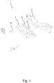
Fig. 1 shows an exploded perspective view of a frame hinge part; -
Fig. 2 shows a perspective view of a frame hinge part; -
Fig. 3 shows a perspective view of a sash hinge part; -
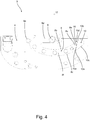
Fig. 4 shows a side view of a sash hinge part; -
Fig. 5 shows a cross-sectional view of a hinge according to the invention; -
Fig. 6 shows a cross-sectional view of a hinge at an intermediate position; -
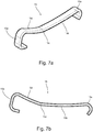
Fig. 7a shows a perspective view of a leaf spring; -
Fig. 7b shows a side view of a leaf spring; -
Fig. 8a shows a perspective view of a first embodiment of a guide pin; -
Fig. 8b shows a side view of the first embodiment of the guide pin shown inFig. 8a ; -
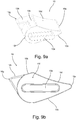
Fig. 9a shows a perspective view of a second embodiment of a guide pin; -
Fig. 9b shows a side view of the second embodiment of the guide pin shown inFig. 9a ; -
Fig. 10 shows a hinge moment of a prior art hinge as a function of open angle; -
Fig. 11 shows a hinge moment of a hinge according to the invention as a function of open angle; -
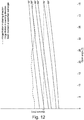
Fig. 12 shows a hinge moment of a prior art hinge as a function of open angle; -
Fig. 13 shows a hinge moment of a hinge according to the invention, incorporating only a new guide pin and an existing leaf spring, as a function of open angle; - Referring first to
Figs 1 to 6 , a general overview of the components of a hinge according to the invention will first be given. - In a manner known per se, the hinge is configured to be installed in a pivotal window with a frame and a sash connected to the frame. The hinge is configured to provide a pivoting movement for the window in that the sash is able to turn relative to the frame about a hinge axis represented by
reference numeral 17 inFigs 4 to 6 . - The hinge comprises a
first hinge part 1 to be secured on the frame and including afirst base plate 2, a braking device with aleaf spring 15, and control means in the form of an arc shaped, preferably circular-arc shaped,guide 7, and asecond hinge part 3 to be secured on the sash and including asecond base plate 4 and an engagement set with aslide bar 8 and aguide pin 10. As shown, theguide 7 is defined in aplate piece 6 of thefirst hinge part 1 and comprises a convex side or wall and a concave side or wall. Opposite theguide 7, arecess 14 is formed in theplate piece 6. As in traditional hinges, the slide bar has aconcave side 8b, aconvex side 8c and ahinge end 8d connected to ahinge pin 9 mounted on thesecond base plate 4. Finally, astop pin 9a is provided on thebase plate 4 as in traditional hinges. As a feature according to the invention, the slide bar is here provided with aleading end 8a with asurface 8e to be accommodated by agap surface 10d of theguide pin 10 to be described in further detail below. - During operation, the arc shaped
guide 7 cooperates with the engagement set, theslide bar 8 being adapted to fit in theguide 7 and being rotationally mounted on thesecond base plate 4, theguide pin 10 being mounted on thesecond base plate 4. - The
leaf spring 15 is, during at least a part of the pivoting movement, in a frictional engagement with at least one element of the engagement set of thesecond hinge part 3. Which part depends on the actual position of the element in question. - As shown in particular in
Fig. 6 and referring now also toFigs 7a-7b and8a-8b , respectively, theleaf spring 15 includes at least oneelbow portion 15c and theguide pin 10 comprises atensioning projection 10a. In the embodiment shown, theguide pin 10 has a cross section shaped as a droplet, in which thetensioning projection 10a is associated with aconcave side 10b and aconvex side 10c opposite thegap surface 10d. The material of theguide pin 10 is chosen to provide the frictional and wearability properties aimed at, and is typically made of steel. One specific material that has proven to function well is the commercially available VN 24.H20005.96. The leaf spring may be provided according to the EN 10270-1 standard and is typically made of steel. - In a closed position of the window, corresponding to the position shown in
Fig. 5 , there is a slight distance between thetensioning projection 10a of theguide pin 10 and theslide bar 8 along a tangential direction of the convex side of theguide 7. The distance may be chosen according to the specific field of application of the hinge; typically, the distance is less than 10 mm. preferably less than 5 mm, more preferably less than 2 mm. - Furthermore, and referring still to the closed position of the window, the
slide bar 8 and theguide pin 10 define agap 16 comprising acentral section 16a having substantially parallel edges and preferably a width less than 5 mm, more preferably less than 3 mm, even more preferably less than 2 mm. - The form of the guide pin may in principle be chosen in any suitable manner. In the embodiment shown and presently preferred, the
guide pin 10 comprises a circular arc shaped surface with a centre of curvature substantially located at, preferably coinciding with, the rotational axis of theslide bar 8. - Turning now to the
leaf spring 15 and referring specifically toFigs. 1 and7a-7b , it is presently preferred that theleaf spring 15 includes a plurality of portions. These portions include afirst end portion 15a connected to a firstcurved portion 15b connected by theelbow portion 15c to a secondcurved portion 15d connected to asecond end portion 15e. Thefirst end portion 15a is adapted to connect to afirst pin 5a of thefirst hinge part 1, and thesecond end portion 15e is adapted to connect to asecond pin 5b of thefirst hinge part 1. The firstcurved portion 15b and the secondcurved portion 15d are preferably circular arc shaped. - Furthermore, the
leaf spring 15 is in the embodiment shown adapted to abut athird pin 5c of thefirst hinge part 1 during at least part of the pivotal movement of the window. - The
second end portion 15e is adapted to connect to asecond pin 5b of thefirst hinge part 1 in an operation position and in an assembly position, the operation position being the position of the pin when the window is in a mounted state, and the assembly position being a position where the connection and/or disconnection of thefirst end portion 15a to thesecond pin 5b is allowed. - The specific shape of the
leaf spring 15 along the path from one end to the other will typically be chosen according to the requirements to the hinge in accordance with factors such as the size and weight of the components of the window, most importantly the weight of the pane and the sash. In the preferred embodiment shown and described herein, the centre of curvature of the firstcurved portion 15b is different from the centre of curvature of the secondcurved portion 15d. - Correspondingly, the radius of curvature of the second
curved portion 15d is in the interval of 80 - 160 mm, preferably in the interval of 100 - 140 mm, more preferably in the interval of 110 - 130 mm. - Regarding the radius of curvature of the first
curved portion 15b, this may in principle be chosen in any suitable manner, ranging from a radius of curvature smaller than the secondcurved portion 15d up to substantially straight. Preferably, the radius of curvature is larger than 70 mm, for instance 74 mm. - The connection between the guide pin and the base plate may in principle be carried out in any suitable manner. In the preferred embodiment, the
guide pin 10 is nonrotatably fixed to thesecond base plate 4 such that theguide pin 10 is not allowed to rotate in relation to thesecond base plate 4. Specifically, this is carried out by means of theoblong mounting projection 10e protruding from a side of thebody 10f of theguide pin 10 but other ways of ensuring the nonrotatability is conceivable as well. - In the above specification describes a first embodiment of the
guide pin 10 as shown inFigs. 2-6 and8a-8b . Turning to a second embodiment of theguide 10 as shown inFigs. 9a-9b . The second embodiment of theguide pin 10 corresponds to the first embodiment except in that, this second embodiment of theguide pin 10 includes anose 10g positioned on an opposite side of theguide pin 10 relative to thetensioning projection 10a. Thenose 10g comprises a side adjacent to theconcave side 10b of theguide pin 10 and forms an integral and continuous surface, which is configured to press against a side of theguide 7 opposite theleaf spring 15 during at least a part of the pivoting movement of the window. Thenose 10g extends less than thebody 10f of theguide pin 10 in a direction of the hinge axis so that the nose fits in a spacing between theplate piece 6 and thefirst base plate 2 when the hinge is in the closed position. -
Figs. 10 to 13 are graphs showing computer simulated curves for the hinge moments in Nm relative to the opening angle degree are shown for various roof inclinations. The dashed and the dotted lines respectively indicate the hinge moment in the closing direction and in the opening direction. The solid lines indicate the sash moment when a roof window is installed at various different roof angles. The hinge friction in the closing direction should be greater than the sash moment, while the hinge friction in the opening direction should be lower than the sash moment. As seen inFig. 10 , for opening angles above about 35 degrees when the roof angle is below 45 degrees, the hinge friction in the closing direction drops below the sash moment which causes the window to close. -
Fig. 11 shows the improvement in hinge friction when incorporating a hinge according to the invention in a roof window with the sash moment characteristics as shown inFig. 10 . The hinge friction in the closing direction no longer sharply drops and stays above the sash moment for the indicated roof angles. In addition, the difference between hinge friction in the opening direction and the sash moment for all indicated opening angles has also increased. -
Fig. 12 shows a different prior art window than inFig. 10 and thus the curves are somewhat different. In this case the hinge friction in the closing direction drops below the sash moment at around 25 degrees, while the hinge friction in the opening direction is above the sash moment at 90 degrees for all opening angles between 0 degrees to 45 degrees. -
Fig. 13 shows the improvement in hinge friction when incorporating a hinge according to the invention in a roof window with the sash moment characteristics as shown inFig. 12 , where the hinge incorporates only a new guide pin and an existing leaf spring. The hinge friction in the closing direction now stays above the sash moment at 15 degrees for all opening angles. In addition, the negative moment of the hinge friction in the opening direction is increased such that it falls below the sash moment at a 90 degree roof angle at an opening angle of about 30 degrees. It should be understood that a new guide pin provides the desired friction, while the combination of a guide pin and a leaf spring according to the invention may provide additional friction. - It should be noted that the above description of preferred embodiments serves only as an example, and that a person skilled in the art will know that numerous variations are possible without deviating from the scope of the claims.
-
- 1
- first hinge part
- 2
- first base plate
- 3
- second hinge part
- 4
- second base plate
- 5a
- first pin
- 5b
- second pin
- 5c
- third pin
- 6
- plate piece
- 7
- guide
- 8
- slide bar
- 8a
- leading end
- 8b
- concave side
- 8c
- convex side
- 8d
- hinge end
- 8e
- surface
- 9
- hinge pin
- 9a
- stop pin
- 10
- guide pin
- 10a
- tensioning projection
- 10b
- concave side
- 10c
- convex side
- 10d
- gap surface
- 10e
- mounting projection
- 10f
- body
- 10g
- nose
- 14
- recess
- 15
- leaf spring
- 15a
- first end portion
- 15b
- first curved portion
- 15c
- elbow portion
- 15d
- second curved portion
- 15e
- second end portion
- 16
- gap
- 16a
- central section
- 17
- hinge axis
Claims (15)
- A hinge for a pivotal window with a frame and a sash connected to the frame, the hinge providing a pivoting movement for the window about a hinge axis (17) and comprising;
a first hinge part (1) to be secured on the frame and including a first base plate (2), a braking device with a leaf spring (15), and control means in the form of an arc shaped, preferably circular-arc shaped, guide (7);
a second hinge part (3) to be secured on the sash and including a second base plate (4) and an engagement set with a slide bar (8) and a guide pin (10),
wherein the arc shaped, preferably circular-arc shaped, guide (7) cooperates with the engagement set, the slide bar (8) being adapted to fit in the guide (7) and being rotationally mounted on the second base plate (4), the guide pin (10) being mounted on the second base plate (4),
wherein the leaf spring (15) is, during at least a part of the pivoting movement, in a frictional engagement with at least one element of the engagement set of the second hinge part (3),
characterised in that the guide pin (10) comprises a tensioning projection (10a) and an adjoining convex side (10c). - A hinge according to claim 1, wherein the tensioning projection (10a) of the guide pin (10) is positioned to face the slide bar (8) during at least a part of the pivoting movement.
- A hinge according to any one of the preceding claims, wherein the guide pin (10) comprises a concave side positioned opposite the convex side (10c) and configured to be in a frictional engagement with a side of the guide (7) opposite the leaf spring (15), wherein the guide pin (10) further comprises a nose (10g) positioned adjacently to the concave side and opposite the tensioning projection (10a).
- A hinge according to according to any one of the preceding claims, wherein, in a closed position of the window, a distance between the tensioning projection (10a) of the guide pin (10) and the slide bar (8) along a tangential direction of a convex side of the guide (7) being less than 10 mm, preferably less than 5 mm, more preferably less than 2 mm.
- A hinge according to any one of the preceding claims, wherein, in a closed position of the window, the slide bar (8) and the guide pin (10) defining a gap (16) comprising a central section (16a) having substantially parallel edges and preferably a width less than 5 mm, more preferably less than 3 mm, even more preferably less than 2 mm.
- A hinge according to any one of the preceding claims, wherein the guide pin (10) comprises a circular arc shaped surface with a centre of curvature substantially located at, preferably coinciding with, the rotational axis of the slide bar (8).
- A hinge according to any one of the preceding claims, wherein the leaf spring (15) includes at least one elbow portion (15c).
- A hinge according to any one of the preceding claims, wherein the leaf spring (15) includes a plurality of portions; a first end portion (15a) connected to a first curved portion (15b) connected by the elbow portion (15c) to a second curved portion (15d) connected to a second end portion (15e), wherein the first end portion (15a) being adapted to connect to a first pin (5a) of the first hinge part (1), and wherein the second end portion (15e) being adapted to connect to a second pin (5b) of the first hinge part (1), and wherein the first curved portion (15b) and the second curved portion (15d) are preferably circular arc shaped.
- A hinge according to claim 7, wherein the leaf spring (15) is adapted to abut a third pin (5c) of the first hinge part (1) during at least part of the pivotal movement of the window.
- A hinge according to any one of claims 7 and 8, wherein the second end portion (15e) is adapted to connect to the second pin (5b) of the first hinge part (1) in an operation position and in an assembly position, the operation position being the position of the pin when the window is in a mounted state, and the assembly position being a position where the connection and/or disconnection of the first end portion (15a) to the second pin (5b) is allowed.
- A hinge according to any one of claims 7 to 9, wherein the centre of curvature of the first curved portion (15b) is different from the centre of curvature of the second curved portion (15d).
- A hinge according to any one of claims 7 to 10, wherein the radius of curvature of the first curved portion (15b) is at least 70 mm.
- A hinge according to any one of claims 7 to 11, wherein the radius of curvature of the second curved portion (15d) is in the interval of 80 - 160 mm, preferably in the interval of 100 - 140 mm, more preferably in the interval of 110 - 130 mm.
- A hinge according to any of the preceding claims, wherein the guide pin (10) is nonrotatably fixed to the second base plate (4) such that the guide pin (10) is not allowed to rotate in relation to the second base plate (4).
- A hinge according to any one of the preceding claims, wherein the guide pin (10) has a droplet shaped cross section in a cross-sectional plane normal to the hinge axis.
Applications Claiming Priority (1)
| Application Number | Priority Date | Filing Date | Title |
|---|---|---|---|
| DKPA201770876 | 2017-11-21 |
Publications (2)
| Publication Number | Publication Date |
|---|---|
| EP3486413A1 true EP3486413A1 (en) | 2019-05-22 |
| EP3486413B1 EP3486413B1 (en) | 2024-01-10 |
Family
ID=64426749
Family Applications (1)
| Application Number | Title | Priority Date | Filing Date |
|---|---|---|---|
| EP18207522.6A Active EP3486413B1 (en) | 2017-11-21 | 2018-11-21 | A pivot hinge having improved frictional properties |
Country Status (2)
| Country | Link |
|---|---|
| EP (1) | EP3486413B1 (en) |
| PL (1) | PL3486413T3 (en) |
Cited By (6)
| Publication number | Priority date | Publication date | Assignee | Title |
|---|---|---|---|---|
| CN110578436A (en) * | 2019-10-12 | 2019-12-17 | 黄椿格 | Annular self-locking buffer door spindle |
| EP3828360A1 (en) | 2019-11-29 | 2021-06-02 | VKR Holding A/S | A window installation system, and a method of installing a roof window |
| EP3872274A1 (en) | 2020-02-27 | 2021-09-01 | VKR Holding A/S | A window installation system, and a method of installing a roof window |
| EP3916187A1 (en) | 2020-05-29 | 2021-12-01 | VKR Holding A/S | A roof window installation system, and a method of installing a roof window |
| EP3971363A1 (en) | 2020-09-22 | 2022-03-23 | VKR Holding A/S | A roof window with an improved pane element, and a method of manufacturing a roof window |
| EP4116532A1 (en) | 2021-07-05 | 2023-01-11 | VKR Holding A/S | Handling and installation assembly for a roof window |
Citations (4)
| Publication number | Priority date | Publication date | Assignee | Title |
|---|---|---|---|---|
| WO1985002646A1 (en) * | 1983-12-15 | 1985-06-20 | V. Kann Rasmussen Holding A/S | Hinge device with brake spring for tilting windows |
| WO2001031155A1 (en) * | 1999-10-22 | 2001-05-03 | Keystone Lintels Limited | Hinge for pivot windows |
| EP1612352A1 (en) * | 2004-07-02 | 2006-01-04 | VKR Holding A/S | Hinge fitting for a pivotal window |
| EP2339103A2 (en) * | 2009-12-22 | 2011-06-29 | VKR Holding A/S | Hinge for pivot windows |
-
2018
- 2018-11-21 PL PL18207522.6T patent/PL3486413T3/en unknown
- 2018-11-21 EP EP18207522.6A patent/EP3486413B1/en active Active
Patent Citations (4)
| Publication number | Priority date | Publication date | Assignee | Title |
|---|---|---|---|---|
| WO1985002646A1 (en) * | 1983-12-15 | 1985-06-20 | V. Kann Rasmussen Holding A/S | Hinge device with brake spring for tilting windows |
| WO2001031155A1 (en) * | 1999-10-22 | 2001-05-03 | Keystone Lintels Limited | Hinge for pivot windows |
| EP1612352A1 (en) * | 2004-07-02 | 2006-01-04 | VKR Holding A/S | Hinge fitting for a pivotal window |
| EP2339103A2 (en) * | 2009-12-22 | 2011-06-29 | VKR Holding A/S | Hinge for pivot windows |
Cited By (7)
| Publication number | Priority date | Publication date | Assignee | Title |
|---|---|---|---|---|
| CN110578436A (en) * | 2019-10-12 | 2019-12-17 | 黄椿格 | Annular self-locking buffer door spindle |
| CN110578436B (en) * | 2019-10-12 | 2021-03-12 | 江苏亚太特种铸钢厂有限公司 | Annular self-locking buffer door spindle |
| EP3828360A1 (en) | 2019-11-29 | 2021-06-02 | VKR Holding A/S | A window installation system, and a method of installing a roof window |
| EP3872274A1 (en) | 2020-02-27 | 2021-09-01 | VKR Holding A/S | A window installation system, and a method of installing a roof window |
| EP3916187A1 (en) | 2020-05-29 | 2021-12-01 | VKR Holding A/S | A roof window installation system, and a method of installing a roof window |
| EP3971363A1 (en) | 2020-09-22 | 2022-03-23 | VKR Holding A/S | A roof window with an improved pane element, and a method of manufacturing a roof window |
| EP4116532A1 (en) | 2021-07-05 | 2023-01-11 | VKR Holding A/S | Handling and installation assembly for a roof window |
Also Published As
| Publication number | Publication date |
|---|---|
| EP3486413B1 (en) | 2024-01-10 |
| PL3486413T3 (en) | 2024-06-17 |
Similar Documents
| Publication | Publication Date | Title |
|---|---|---|
| EP3486413B1 (en) | A pivot hinge having improved frictional properties | |
| EP0112681A1 (en) | Improvement in friction supporting stays | |
| US7047600B2 (en) | Egress 4-bar hinge assembly | |
| EP3001077A1 (en) | Anti-flutter check valve | |
| EP1881143A2 (en) | Furniture hinge | |
| CZ296380B6 (en) | Device, which safeguards people against falling | |
| CA2285835C (en) | Hinge mechanism | |
| US6701577B1 (en) | Barbecue grill hinge assembly | |
| EP1290304B1 (en) | Hinge for pivot windows | |
| US20210262270A1 (en) | Door closers | |
| EP2339103A2 (en) | Hinge for pivot windows | |
| CN108825028A (en) | A kind of sliding door movable pulley sub-assembly | |
| EP3348763B1 (en) | Intermediate arm assembly for a dual-function roof window | |
| GB2225378A (en) | Improvements in friction stay hinges | |
| US12398587B1 (en) | Window hinge assembly and methods | |
| WO2007000570A2 (en) | Sash hinge | |
| US8894137B2 (en) | Open roof construction for a vehicle | |
| EP1612352B1 (en) | Hinge fitting for a pivotal window | |
| EP4226006B1 (en) | A door hinge for household appliances | |
| EP3299536B1 (en) | A roof window including a set of hinges with improved movement pattern | |
| DK2489819T3 (en) | Hinge | |
| US20060207056A1 (en) | Door closer device | |
| GB2228043A (en) | Friction stay hinges | |
| GB2236798A (en) | Improvements in or relating to friction stay-hinges | |
| US20090241423A1 (en) | Overhead garage door hinging top bracket |
Legal Events
| Date | Code | Title | Description |
|---|---|---|---|
| PUAI | Public reference made under article 153(3) epc to a published international application that has entered the european phase |
Free format text: ORIGINAL CODE: 0009012 |
|
| STAA | Information on the status of an ep patent application or granted ep patent |
Free format text: STATUS: THE APPLICATION HAS BEEN PUBLISHED |
|
| AK | Designated contracting states |
Kind code of ref document: A1 Designated state(s): AL AT BE BG CH CY CZ DE DK EE ES FI FR GB GR HR HU IE IS IT LI LT LU LV MC MK MT NL NO PL PT RO RS SE SI SK SM TR |
|
| AX | Request for extension of the european patent |
Extension state: BA ME |
|
| STAA | Information on the status of an ep patent application or granted ep patent |
Free format text: STATUS: REQUEST FOR EXAMINATION WAS MADE |
|
| 17P | Request for examination filed |
Effective date: 20191122 |
|
| RBV | Designated contracting states (corrected) |
Designated state(s): AL AT BE BG CH CY CZ DE DK EE ES FI FR GB GR HR HU IE IS IT LI LT LU LV MC MK MT NL NO PL PT RO RS SE SI SK SM TR |
|
| STAA | Information on the status of an ep patent application or granted ep patent |
Free format text: STATUS: EXAMINATION IS IN PROGRESS |
|
| 17Q | First examination report despatched |
Effective date: 20230330 |
|
| GRAP | Despatch of communication of intention to grant a patent |
Free format text: ORIGINAL CODE: EPIDOSNIGR1 |
|
| STAA | Information on the status of an ep patent application or granted ep patent |
Free format text: STATUS: GRANT OF PATENT IS INTENDED |
|
| INTG | Intention to grant announced |
Effective date: 20231009 |
|
| GRAS | Grant fee paid |
Free format text: ORIGINAL CODE: EPIDOSNIGR3 |
|
| GRAA | (expected) grant |
Free format text: ORIGINAL CODE: 0009210 |
|
| STAA | Information on the status of an ep patent application or granted ep patent |
Free format text: STATUS: THE PATENT HAS BEEN GRANTED |
|
| AK | Designated contracting states |
Kind code of ref document: B1 Designated state(s): AL AT BE BG CH CY CZ DE DK EE ES FI FR GB GR HR HU IE IS IT LI LT LU LV MC MK MT NL NO PL PT RO RS SE SI SK SM TR |
|
| REG | Reference to a national code |
Ref country code: GB Ref legal event code: FG4D |
|
| REG | Reference to a national code |
Ref country code: CH Ref legal event code: EP |
|
| REG | Reference to a national code |
Ref country code: DE Ref legal event code: R096 Ref document number: 602018063915 Country of ref document: DE |
|
| REG | Reference to a national code |
Ref country code: IE Ref legal event code: FG4D |
|
| REG | Reference to a national code |
Ref country code: LT Ref legal event code: MG9D |
|
| REG | Reference to a national code |
Ref country code: NL Ref legal event code: MP Effective date: 20240110 |
|
| REG | Reference to a national code |
Ref country code: AT Ref legal event code: MK05 Ref document number: 1649027 Country of ref document: AT Kind code of ref document: T Effective date: 20240110 |
|
| PG25 | Lapsed in a contracting state [announced via postgrant information from national office to epo] |
Ref country code: NL Free format text: LAPSE BECAUSE OF FAILURE TO SUBMIT A TRANSLATION OF THE DESCRIPTION OR TO PAY THE FEE WITHIN THE PRESCRIBED TIME-LIMIT Effective date: 20240110 |
|
| PG25 | Lapsed in a contracting state [announced via postgrant information from national office to epo] |
Ref country code: NL Free format text: LAPSE BECAUSE OF FAILURE TO SUBMIT A TRANSLATION OF THE DESCRIPTION OR TO PAY THE FEE WITHIN THE PRESCRIBED TIME-LIMIT Effective date: 20240110 |
|
| PG25 | Lapsed in a contracting state [announced via postgrant information from national office to epo] |
Ref country code: IS Free format text: LAPSE BECAUSE OF FAILURE TO SUBMIT A TRANSLATION OF THE DESCRIPTION OR TO PAY THE FEE WITHIN THE PRESCRIBED TIME-LIMIT Effective date: 20240510 |
|
| PG25 | Lapsed in a contracting state [announced via postgrant information from national office to epo] |
Ref country code: LT Free format text: LAPSE BECAUSE OF FAILURE TO SUBMIT A TRANSLATION OF THE DESCRIPTION OR TO PAY THE FEE WITHIN THE PRESCRIBED TIME-LIMIT Effective date: 20240110 |
|
| PG25 | Lapsed in a contracting state [announced via postgrant information from national office to epo] |
Ref country code: GR Free format text: LAPSE BECAUSE OF FAILURE TO SUBMIT A TRANSLATION OF THE DESCRIPTION OR TO PAY THE FEE WITHIN THE PRESCRIBED TIME-LIMIT Effective date: 20240411 |
|
| PG25 | Lapsed in a contracting state [announced via postgrant information from national office to epo] |
Ref country code: RS Free format text: LAPSE BECAUSE OF FAILURE TO SUBMIT A TRANSLATION OF THE DESCRIPTION OR TO PAY THE FEE WITHIN THE PRESCRIBED TIME-LIMIT Effective date: 20240410 Ref country code: HR Free format text: LAPSE BECAUSE OF FAILURE TO SUBMIT A TRANSLATION OF THE DESCRIPTION OR TO PAY THE FEE WITHIN THE PRESCRIBED TIME-LIMIT Effective date: 20240110 |
|
| PG25 | Lapsed in a contracting state [announced via postgrant information from national office to epo] |
Ref country code: ES Free format text: LAPSE BECAUSE OF FAILURE TO SUBMIT A TRANSLATION OF THE DESCRIPTION OR TO PAY THE FEE WITHIN THE PRESCRIBED TIME-LIMIT Effective date: 20240110 |
|
| PG25 | Lapsed in a contracting state [announced via postgrant information from national office to epo] |
Ref country code: AT Free format text: LAPSE BECAUSE OF FAILURE TO SUBMIT A TRANSLATION OF THE DESCRIPTION OR TO PAY THE FEE WITHIN THE PRESCRIBED TIME-LIMIT Effective date: 20240110 |
|
| PG25 | Lapsed in a contracting state [announced via postgrant information from national office to epo] |
Ref country code: RS Free format text: LAPSE BECAUSE OF FAILURE TO SUBMIT A TRANSLATION OF THE DESCRIPTION OR TO PAY THE FEE WITHIN THE PRESCRIBED TIME-LIMIT Effective date: 20240410 Ref country code: NO Free format text: LAPSE BECAUSE OF FAILURE TO SUBMIT A TRANSLATION OF THE DESCRIPTION OR TO PAY THE FEE WITHIN THE PRESCRIBED TIME-LIMIT Effective date: 20240410 Ref country code: LT Free format text: LAPSE BECAUSE OF FAILURE TO SUBMIT A TRANSLATION OF THE DESCRIPTION OR TO PAY THE FEE WITHIN THE PRESCRIBED TIME-LIMIT Effective date: 20240110 Ref country code: IS Free format text: LAPSE BECAUSE OF FAILURE TO SUBMIT A TRANSLATION OF THE DESCRIPTION OR TO PAY THE FEE WITHIN THE PRESCRIBED TIME-LIMIT Effective date: 20240510 Ref country code: HR Free format text: LAPSE BECAUSE OF FAILURE TO SUBMIT A TRANSLATION OF THE DESCRIPTION OR TO PAY THE FEE WITHIN THE PRESCRIBED TIME-LIMIT Effective date: 20240110 Ref country code: GR Free format text: LAPSE BECAUSE OF FAILURE TO SUBMIT A TRANSLATION OF THE DESCRIPTION OR TO PAY THE FEE WITHIN THE PRESCRIBED TIME-LIMIT Effective date: 20240411 Ref country code: ES Free format text: LAPSE BECAUSE OF FAILURE TO SUBMIT A TRANSLATION OF THE DESCRIPTION OR TO PAY THE FEE WITHIN THE PRESCRIBED TIME-LIMIT Effective date: 20240110 Ref country code: BG Free format text: LAPSE BECAUSE OF FAILURE TO SUBMIT A TRANSLATION OF THE DESCRIPTION OR TO PAY THE FEE WITHIN THE PRESCRIBED TIME-LIMIT Effective date: 20240110 Ref country code: AT Free format text: LAPSE BECAUSE OF FAILURE TO SUBMIT A TRANSLATION OF THE DESCRIPTION OR TO PAY THE FEE WITHIN THE PRESCRIBED TIME-LIMIT Effective date: 20240110 |
|
| PG25 | Lapsed in a contracting state [announced via postgrant information from national office to epo] |
Ref country code: PT Free format text: LAPSE BECAUSE OF FAILURE TO SUBMIT A TRANSLATION OF THE DESCRIPTION OR TO PAY THE FEE WITHIN THE PRESCRIBED TIME-LIMIT Effective date: 20240510 |
|
| PG25 | Lapsed in a contracting state [announced via postgrant information from national office to epo] |
Ref country code: SE Free format text: LAPSE BECAUSE OF FAILURE TO SUBMIT A TRANSLATION OF THE DESCRIPTION OR TO PAY THE FEE WITHIN THE PRESCRIBED TIME-LIMIT Effective date: 20240110 Ref country code: PT Free format text: LAPSE BECAUSE OF FAILURE TO SUBMIT A TRANSLATION OF THE DESCRIPTION OR TO PAY THE FEE WITHIN THE PRESCRIBED TIME-LIMIT Effective date: 20240510 Ref country code: LV Free format text: LAPSE BECAUSE OF FAILURE TO SUBMIT A TRANSLATION OF THE DESCRIPTION OR TO PAY THE FEE WITHIN THE PRESCRIBED TIME-LIMIT Effective date: 20240110 |
|
| PG25 | Lapsed in a contracting state [announced via postgrant information from national office to epo] |
Ref country code: DK Free format text: LAPSE BECAUSE OF FAILURE TO SUBMIT A TRANSLATION OF THE DESCRIPTION OR TO PAY THE FEE WITHIN THE PRESCRIBED TIME-LIMIT Effective date: 20240110 |
|
| REG | Reference to a national code |
Ref country code: DE Ref legal event code: R097 Ref document number: 602018063915 Country of ref document: DE |
|
| PG25 | Lapsed in a contracting state [announced via postgrant information from national office to epo] |
Ref country code: SM Free format text: LAPSE BECAUSE OF FAILURE TO SUBMIT A TRANSLATION OF THE DESCRIPTION OR TO PAY THE FEE WITHIN THE PRESCRIBED TIME-LIMIT Effective date: 20240110 |
|
| PG25 | Lapsed in a contracting state [announced via postgrant information from national office to epo] |
Ref country code: EE Free format text: LAPSE BECAUSE OF FAILURE TO SUBMIT A TRANSLATION OF THE DESCRIPTION OR TO PAY THE FEE WITHIN THE PRESCRIBED TIME-LIMIT Effective date: 20240110 Ref country code: CZ Free format text: LAPSE BECAUSE OF FAILURE TO SUBMIT A TRANSLATION OF THE DESCRIPTION OR TO PAY THE FEE WITHIN THE PRESCRIBED TIME-LIMIT Effective date: 20240110 |
|
| PG25 | Lapsed in a contracting state [announced via postgrant information from national office to epo] |
Ref country code: SK Free format text: LAPSE BECAUSE OF FAILURE TO SUBMIT A TRANSLATION OF THE DESCRIPTION OR TO PAY THE FEE WITHIN THE PRESCRIBED TIME-LIMIT Effective date: 20240110 |
|
| PG25 | Lapsed in a contracting state [announced via postgrant information from national office to epo] |
Ref country code: SM Free format text: LAPSE BECAUSE OF FAILURE TO SUBMIT A TRANSLATION OF THE DESCRIPTION OR TO PAY THE FEE WITHIN THE PRESCRIBED TIME-LIMIT Effective date: 20240110 Ref country code: SK Free format text: LAPSE BECAUSE OF FAILURE TO SUBMIT A TRANSLATION OF THE DESCRIPTION OR TO PAY THE FEE WITHIN THE PRESCRIBED TIME-LIMIT Effective date: 20240110 Ref country code: RO Free format text: LAPSE BECAUSE OF FAILURE TO SUBMIT A TRANSLATION OF THE DESCRIPTION OR TO PAY THE FEE WITHIN THE PRESCRIBED TIME-LIMIT Effective date: 20240110 Ref country code: EE Free format text: LAPSE BECAUSE OF FAILURE TO SUBMIT A TRANSLATION OF THE DESCRIPTION OR TO PAY THE FEE WITHIN THE PRESCRIBED TIME-LIMIT Effective date: 20240110 Ref country code: DK Free format text: LAPSE BECAUSE OF FAILURE TO SUBMIT A TRANSLATION OF THE DESCRIPTION OR TO PAY THE FEE WITHIN THE PRESCRIBED TIME-LIMIT Effective date: 20240110 Ref country code: CZ Free format text: LAPSE BECAUSE OF FAILURE TO SUBMIT A TRANSLATION OF THE DESCRIPTION OR TO PAY THE FEE WITHIN THE PRESCRIBED TIME-LIMIT Effective date: 20240110 |
|
| PLBE | No opposition filed within time limit |
Free format text: ORIGINAL CODE: 0009261 |
|
| STAA | Information on the status of an ep patent application or granted ep patent |
Free format text: STATUS: NO OPPOSITION FILED WITHIN TIME LIMIT |
|
| PG25 | Lapsed in a contracting state [announced via postgrant information from national office to epo] |
Ref country code: IT Free format text: LAPSE BECAUSE OF FAILURE TO SUBMIT A TRANSLATION OF THE DESCRIPTION OR TO PAY THE FEE WITHIN THE PRESCRIBED TIME-LIMIT Effective date: 20240110 |
|
| 26N | No opposition filed |
Effective date: 20241011 |
|
| PG25 | Lapsed in a contracting state [announced via postgrant information from national office to epo] |
Ref country code: IT Free format text: LAPSE BECAUSE OF FAILURE TO SUBMIT A TRANSLATION OF THE DESCRIPTION OR TO PAY THE FEE WITHIN THE PRESCRIBED TIME-LIMIT Effective date: 20240110 |
|
| PG25 | Lapsed in a contracting state [announced via postgrant information from national office to epo] |
Ref country code: SI Free format text: LAPSE BECAUSE OF FAILURE TO SUBMIT A TRANSLATION OF THE DESCRIPTION OR TO PAY THE FEE WITHIN THE PRESCRIBED TIME-LIMIT Effective date: 20240110 |
|
| REG | Reference to a national code |
Ref country code: CH Ref legal event code: PL |
|
| PG25 | Lapsed in a contracting state [announced via postgrant information from national office to epo] |
Ref country code: MC Free format text: LAPSE BECAUSE OF FAILURE TO SUBMIT A TRANSLATION OF THE DESCRIPTION OR TO PAY THE FEE WITHIN THE PRESCRIBED TIME-LIMIT Effective date: 20240110 |
|
| PG25 | Lapsed in a contracting state [announced via postgrant information from national office to epo] |
Ref country code: LU Free format text: LAPSE BECAUSE OF NON-PAYMENT OF DUE FEES Effective date: 20241121 |
|
| REG | Reference to a national code |
Ref country code: CH Ref legal event code: PL |
|
| GBPC | Gb: european patent ceased through non-payment of renewal fee |
Effective date: 20241121 |
|
| PG25 | Lapsed in a contracting state [announced via postgrant information from national office to epo] |
Ref country code: CH Free format text: LAPSE BECAUSE OF NON-PAYMENT OF DUE FEES Effective date: 20241130 |
|
| REG | Reference to a national code |
Ref country code: BE Ref legal event code: MM Effective date: 20241130 |
|
| PG25 | Lapsed in a contracting state [announced via postgrant information from national office to epo] |
Ref country code: FI Free format text: LAPSE BECAUSE OF FAILURE TO SUBMIT A TRANSLATION OF THE DESCRIPTION OR TO PAY THE FEE WITHIN THE PRESCRIBED TIME-LIMIT Effective date: 20240110 |
|
| PG25 | Lapsed in a contracting state [announced via postgrant information from national office to epo] |
Ref country code: GB Free format text: LAPSE BECAUSE OF NON-PAYMENT OF DUE FEES Effective date: 20241121 Ref country code: BE Free format text: LAPSE BECAUSE OF NON-PAYMENT OF DUE FEES Effective date: 20241130 |
|
| PG25 | Lapsed in a contracting state [announced via postgrant information from national office to epo] |
Ref country code: FR Free format text: LAPSE BECAUSE OF NON-PAYMENT OF DUE FEES Effective date: 20241130 |
|
| PG25 | Lapsed in a contracting state [announced via postgrant information from national office to epo] |
Ref country code: IE Free format text: LAPSE BECAUSE OF NON-PAYMENT OF DUE FEES Effective date: 20241121 |
|
| PGFP | Annual fee paid to national office [announced via postgrant information from national office to epo] |
Ref country code: DE Payment date: 20251007 Year of fee payment: 8 |
|
| PGFP | Annual fee paid to national office [announced via postgrant information from national office to epo] |
Ref country code: PL Payment date: 20251014 Year of fee payment: 8 |
|
| PG25 | Lapsed in a contracting state [announced via postgrant information from national office to epo] |
Ref country code: HU Free format text: LAPSE BECAUSE OF FAILURE TO SUBMIT A TRANSLATION OF THE DESCRIPTION OR TO PAY THE FEE WITHIN THE PRESCRIBED TIME-LIMIT; INVALID AB INITIO Effective date: 20181121 |
|
| PG25 | Lapsed in a contracting state [announced via postgrant information from national office to epo] |
Ref country code: CY Free format text: LAPSE BECAUSE OF FAILURE TO SUBMIT A TRANSLATION OF THE DESCRIPTION OR TO PAY THE FEE WITHIN THE PRESCRIBED TIME-LIMIT; INVALID AB INITIO Effective date: 20181121 |