EP3486398A1 - Stair nosing having integral anti-skid features - Google Patents
Stair nosing having integral anti-skid features Download PDFInfo
- Publication number
- EP3486398A1 EP3486398A1 EP18206549.0A EP18206549A EP3486398A1 EP 3486398 A1 EP3486398 A1 EP 3486398A1 EP 18206549 A EP18206549 A EP 18206549A EP 3486398 A1 EP3486398 A1 EP 3486398A1
- Authority
- EP
- European Patent Office
- Prior art keywords
- stair nosing
- skid
- section
- tread
- feature
- Prior art date
- Legal status (The legal status is an assumption and is not a legal conclusion. Google has not performed a legal analysis and makes no representation as to the accuracy of the status listed.)
- Granted
Links
Images


Classifications
-
- E—FIXED CONSTRUCTIONS
- E04—BUILDING
- E04F—FINISHING WORK ON BUILDINGS, e.g. STAIRS, FLOORS
- E04F11/00—Stairways, ramps, or like structures; Balustrades; Handrails
- E04F11/02—Stairways; Layouts thereof
- E04F11/104—Treads
- E04F11/16—Surfaces thereof; Protecting means for edges or corners thereof
-
- B—PERFORMING OPERATIONS; TRANSPORTING
- B21—MECHANICAL METAL-WORKING WITHOUT ESSENTIALLY REMOVING MATERIAL; PUNCHING METAL
- B21D—WORKING OR PROCESSING OF SHEET METAL OR METAL TUBES, RODS OR PROFILES WITHOUT ESSENTIALLY REMOVING MATERIAL; PUNCHING METAL
- B21D28/00—Shaping by press-cutting; Perforating
- B21D28/02—Punching blanks or articles with or without obtaining scrap; Notching
- B21D28/10—Incompletely punching in such a manner that the parts are still coherent with the work
-
- E—FIXED CONSTRUCTIONS
- E04—BUILDING
- E04F—FINISHING WORK ON BUILDINGS, e.g. STAIRS, FLOORS
- E04F11/00—Stairways, ramps, or like structures; Balustrades; Handrails
- E04F11/02—Stairways; Layouts thereof
- E04F11/104—Treads
- E04F11/112—Treads of metal or with an upper layer of metal
Definitions
- the present disclosure relates to a nosing for installation on a stair.
- Conventional nosings wrap around the edge of the stair, providing a slip resistant surface and reducing wear on the stair covering.
- the present disclosure provides a stair nosing comprising a tread section having a body and defining a tread plane, a riser section extending in a second plane generally perpendicular to the first plane, and a transition section between the tread section and the riser section.
- At least one of the tread section and transition section includes an arrangement of protrusions, with each protrusion including a base edge that is integral with the body and an outwardly extending tab extending upwardly from the tread plane at an acute angle.
- the tab includes at least one edge separated from the body.
- the present disclosure provides a method of manufacturing a stair nosing, the method comprising providing a sheet of material having a first major surface, a second major surface opposing the first major surface, and a body having a thickness; ablating the sheet along a first cut line to create a first feature precursor, the ablation causing the body to be separated along the cut line; and displacing the feature precursor at least partially above the first major surface, wherein at least a portion of the feature precursor remains coupled to the body.
- layer means a single stratum that may be continuous or discontinuous over a surface.
- the terms, “height”, “depth”, “top” and “bottom” are for illustrative purposes only, and do not necessarily define the orientation or the relationship between the surface and the intrusive feature. Accordingly, the terms “height” and “depth”, as well as “top” and “bottom” should be considered interchangeable.
- a As used herein, "a”, “an”, “the”, “at least one” and “one or more” are used interchangeably. Thus, for example, a core comprising "a” pattern of recesses can be interpreted as a core comprising "one or more” patterns.
- the term "generally”, unless otherwise specifically defined, means that the property or attribute would be readily recognizable by a person of ordinary skill but without requiring absolute precision or a perfect match (e.g., within +/- 20 % for quantifiable properties).
- the term “substantially”, unless otherwise specifically defined, means to a high degree of approximation (e.g., within +/- 10% for quantifiable properties) but again without requiring absolute precision or a perfect match. Terms such as same, equal, uniform, constant, strictly, and the like, are understood to be within the usual tolerances or measuring error applicable to the particular circumstance rather than requiring absolute precision or a perfect match.
- a stair nosing 10 in accord with one embodiment of the present disclosure is shown in Figs. 1-3 .
- the stair nosing 10 comprises a tread section 12 and riser section 22, which may be integrally formed or may comprise separate elements fixed together.
- the tread section 12 includes opposing first and second major surfaces 13,14, a leading edge 15, and opposing side edges 17, 18 extending between the leading edge 15 and trailing edge 16.
- the first major surface 13 and side edges 17, 18 cooperate to define a horizontally oriented tread plane.
- the tread section 12 further includes an arrangement of anti-skid features 30.
- a transition section 20 extends along the leading edge 15.
- the transition section 20 is arcuate or otherwise bent and connects the tread section 12 with the riser section 22.
- the riser section 22 extends generally perpendicular to the tread plane and is arranged in a vertical orientation.
- the tread section 12 is adapted to rest atop and be attached to a stair.
- the arcuate transition section 20 is adapted to wrap around a nosing of the stair, with the riser section 22 adjacent the stair riser.
- the transition section 20 includes a plurality of tabs 40.
- the tabs 40 extend laterally across the width of the step 10 and are intended to prevent slippage when engaging the transition section 12.
- the tabs 40 extend to a top edge 42 below the tread plane.
- the top edge 42 is planar and resides in a plane substantially parallel to the tread plane.
- the nosing 10 is substantially L-shaped in cross section, but the angle between the tread section 12 and riser section 22 may be varied to fit the shape of a particular stair edge.
- the angle between the tread section 12 and riser section 14 may be oblique or more particularly less than 90°.
- the arrangement of anti-skid features 30 includes a plurality of rectangular protrusions 32.
- Each protrusion 32 includes a base edge 34 that is integral with the major surface 13 and an outwardly extending tab 35.
- the tab 35 extends upwardly from the tread plane at an acute angle to provide anti-skid surfaces 36 and 37.
- the shape of the protrusion 32 is not particularly limited and can include any suitable shape or combination of shapes. Suitable shapes include, but are not limited to, parallelograms, parallelograms with rounded corners, rectangles, squares, circles, half-circles, ellipses, half-ellipses, triangles, trapezoids, stars, other polygons (e.g., hexagons), etc., and combinations thereof. Typically, however, the shape includes at least one straight edge. As used herein, the shape of the protrusion is defined by the integral base edge 34 and the edges (detached or integral) of the tab 35.
- both anti-skid surfaces 36 and 37 are depicted in cross-section in Figure 3 .
- the bottom edge 38 of the first anti-skid surface 36 is as least adjacent to if not in intimate contact with a wall 28 defined through the thickness of the tread section 12 body.
- the first anti-skid surface represents one edge of a separated portion of the tread section 12 body, with the wall 28 representing the other.
- first 36 and second anti-skid surfaces 37 meet at an angular rather than rounded apex 39.
- the angular apex 39 can provide improved engagement with footwear and attendant resistance to slipping.
- the protrusions 32 are arranged parallel to the longitudinal axis "L" of the tread section 12, as this provides a surface to at least reduce skidding in the general direction of foot traffic up and down a given stair. In other embodiments featuring the same or different shapes, the protrusions 32 may be arranged in any given orientation relative to tread section 12. In some embodiments, features of the tread section can be present on a regular repeating basis, on a random basis, and the like, or combinations thereof. In other embodiments, the features can be present over a portion of the entire area of the tread section 12, or present over the entire area of the tread section 12.
- the nosing 10 is typically formed from a sheet of material or blank.
- the arrangement of anti-skid features 30 is created by using a laser to ablate the thickness of a sheet along one or more edges of the desired protrusion shape, leaving at least one edge remaining joined to the sheet as the base 34.
- the ablation causes a separation (typically 0.1 to 0.3mm) within the body along the path of ablation.
- This process is repeated for each protrusion in the arrangement 30 and can also be used to create tab 40 precursors along a bend line in the sheet.
- the precursor features are then stamped, punched or otherwise displaced in the direction of the one the major surfaces to create the protrusions 32.
- the sheet can then be bent along the bend line to create the tread section, transition section, and riser section. The bending of the sheet results in the formation of tabs 40.
- the present disclosure provides a method for creating an arrangement of anti-skid feature precursors on a surface using laser energy.
- a nosing blank having a major surface is provided and oriented relative to a laser source or scanner. Contaminants on the surface may be removed at this point, according to methods well known in the art.
- Laser parameters relating to a first feature arrangement are defined to control the initial location, spacing, and size of the ablation-created features on the surface.
- Relevant pattern parameters include but are not limited to: 1) distance (i.e ., spacing) between target locations (i.e ., target sites on the surface for receipt of laser energy) in both x and y directions; 2) portion or extent of the metal surface that will include features; 3) laser power and/or wavelength; 4) focal point position of the laser beam relative to the substrate; and optionally 5) repetition rate of laser energy (pulses) directed at the surface.
- the laser beam is moved across a surface of the article at a predetermined path of travel. In other implementations, the surface may be moved relative to the laser beam.
- the laser source discharges laser energy according to the determined laser parameters, cutting through the thickness of the sheet and creating a first portion of the outline of each anti-skid feature on the surface.
- laser energy is generated using a laser source such as, for example, a fiber laser or solid-state laser.
- the first outline portion may be a generally horizontal, vertical, diagonal, sinusoidal, spiral or other linear or non-linear paths, depending on the feature shape(s) and the desired orientation of the first feature arrangement on the metal surface.
- both the ablation and the displacement of features can occur on the same machine.
- Suitable machines including the TruMatic 6000, are available from Trumpf GmbH + Co. KG (Germany).
- the stair nosing 10 is preferably made from metal such as stainless steel, but can be made from any suitable material.
- Suitable metals include, but are not limited to, stainless steel alloys, chromium-cobalt-molybdenum alloys, titanium alloys, zirconium alloys, shape memory nickel-titanium alloys, super elastic nickel-titanium alloys, aluminum alloys, copper alloys, and combinations thereof.
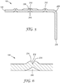
- a stair nosing 100 in accord with another embodiment of the present disclosure is shown in Figs. 4-6 .
- a stair nosing 100 includes a tread section 120 and riser section 220 extending generally perpendicular to the tread section 120 and arranged in a vertical orientation.
- An arcuate transition section 200 connects the tread section 120 to the riser section 220.
- Tread section 120 includes plurality of anti-skid features 230.
- the anti-skid features 230 include a top surface 231 and a cleft 232 extending through only a portion of the thickness of the feature 230.
- the cleft 232 is V-shaped and extends the length of the feature 230.
- the shape of cleft 232 is not particularly limited and can include any suitable shape, or extend along only a portion of the feature 230.
- the V-shape may be particular advantageous in some embodiments, however, as the top points 234 of the V-shape function as engagement points for users.
- a recess 240 is formed on the second major surface 122 of the tread section in the course of displacing the feature 230 from the tread plane. Clefts 232 may also be placed on the transition section 200.
- the nosing 100 is typically formed using methods similar to nosing 10, such that a blank sheet of material is manipulated to have anti-skid properties.
- the arrangement of anti-skid features 230 is created by first removing a portion of the sheet at a predetermined location on the first surface to create a cleft 232. This process is repeated for each feature in the arrangement 230, such that a major surface of the sheet includes a plurality of clefts. The second, opposing surface is then stamped, punched, or otherwise displaced at location of the precursor features to create the protrusions 232. The sheet can then be bent along the bend line to create the tread section, transition section, and riser section.
Landscapes
- Engineering & Computer Science (AREA)
- Architecture (AREA)
- Civil Engineering (AREA)
- Structural Engineering (AREA)
- Mechanical Engineering (AREA)
- Steps, Ramps, And Handrails (AREA)
Abstract
Description
- The present disclosure relates to a nosing for installation on a stair. Conventional nosings wrap around the edge of the stair, providing a slip resistant surface and reducing wear on the stair covering.
- While stair nosing featuring slip resistance (i.e., anti-skid) features are known, the current art suffers from several drawbacks. Stair nosing featuring multiple assembled elements to impart slip resistance may be difficult to manufacture, install, or maintain. Monolithic nosings including stamped or punched anti-skid features, like those described in
US 2014/0013681 (Disch et al. ), typically include a rounded surface that may result in deteriorating slip resistance capabilities over time. Moreover, the creation of these features can often result in a gap or other recess between the body of the stair nosing and the feature. This gap is susceptible to accumulation of debris from the environment and the footwear of the stair climbers. The accumulation is aesthetically unpleasant and can also detract from the anti-skid performance of the nosing. - In one aspect, the present disclosure provides a stair nosing comprising a tread section having a body and defining a tread plane, a riser section extending in a second plane generally perpendicular to the first plane, and a transition section between the tread section and the riser section. At least one of the tread section and transition section includes an arrangement of protrusions, with each protrusion including a base edge that is integral with the body and an outwardly extending tab extending upwardly from the tread plane at an acute angle. The tab includes at least one edge separated from the body.
- In another aspect, the present disclosure provides a method of manufacturing a stair nosing, the method comprising providing a sheet of material having a first major surface, a second major surface opposing the first major surface, and a body having a thickness; ablating the sheet along a first cut line to create a first feature precursor, the ablation causing the body to be separated along the cut line; and displacing the feature precursor at least partially above the first major surface, wherein at least a portion of the feature precursor remains coupled to the body.
- As used herein, "layer" means a single stratum that may be continuous or discontinuous over a surface.
- As used herein, the terms, "height", "depth", "top" and "bottom" are for illustrative purposes only, and do not necessarily define the orientation or the relationship between the surface and the intrusive feature. Accordingly, the terms "height" and "depth", as well as "top" and "bottom" should be considered interchangeable.
- The terms "comprises" and variations thereof do not have a limiting meaning where these terms appear in the description and claims.
- The words "preferred" and "preferably" refer to embodiments of the invention that may afford certain benefits, under certain circumstances. However, other embodiments may also be preferred, under the same or other circumstances. Furthermore, the recitation of one or more preferred embodiments does not imply that other embodiments are not useful, and is not intended to exclude other embodiments from the scope of the invention.
- As recited herein, all numbers should be considered modified by the term "about".
- As used herein, "a", "an", "the", "at least one" and "one or more" are used interchangeably. Thus, for example, a core comprising "a" pattern of recesses can be interpreted as a core comprising "one or more" patterns.
- Also herein, the recitations of numerical ranges by endpoints include all numbers subsumed within that range (e.g., 1 to 5 includes 1, 1.5, 2, 2.75, 3, 3.80, 4, 5, etc.).
- As used herein as a modifier to a property or attribute, the term "generally", unless otherwise specifically defined, means that the property or attribute would be readily recognizable by a person of ordinary skill but without requiring absolute precision or a perfect match (e.g., within +/- 20 % for quantifiable properties). The term "substantially", unless otherwise specifically defined, means to a high degree of approximation (e.g., within +/- 10% for quantifiable properties) but again without requiring absolute precision or a perfect match. Terms such as same, equal, uniform, constant, strictly, and the like, are understood to be within the usual tolerances or measuring error applicable to the particular circumstance rather than requiring absolute precision or a perfect match.
- The above summary of the present disclosure is not intended to describe each disclosed embodiment or every implementation of the present invention. The description that follows more particularly exemplifies illustrative embodiments. In several places throughout the application, guidance is provided through lists of examples, which examples can be used in various combinations. In each instance, the recited list serves only as a representative group and should not be interpreted as an exhaustive list.
-
-
Fig. 1 is a perspective view of an anti-skid stair nosing according to an embodiment of the present disclosure; -
Fig. 2 is a cross-sectional view of the stair nosing ofFig. 1 ; -
Fig. 3 is a cross-sectional view of an anti-skid feature on the stair nosing ofFigs. 1 and 2 ; -
Fig. 4 is a perspective view of an anti-skid stair nosing according to another embodiment of the present disclosure; -
Fig. 5 is a cross-sectional view of the stair nosing ofFig. 1 ; and -
Fig. 6 is a cross-sectional view of an anti-skid feature on the stair nosing ofFigs. 4 and5 . - Layers in certain depicted embodiments are for illustrative purposes only and are not intended to absolutely define the thickness, relative or otherwise, or the absolute location of any component. While the above-identified figures set forth several embodiments of the disclosure other embodiments are also contemplated, as noted in the description. In all cases, this disclosure is presented by way of representation and not limitation. It should be understood that numerous other modifications and embodiments can be devised by those skilled in the art, which fall within the scope and spirit of the principles of the disclosure.
- Various embodiments and implementations will be described in detail. These embodiments should not be construed as limiting the scope of the present application in any manner, and changes and modifications may be made without departing from the spirit and scope of the inventions. Further, only some end uses have been discussed herein, but end uses not specifically described herein are included within the scope of the present application. As such, the scope of the present application should be determined by the claims. The terms "vertical", "horizontal", "leading", "trailing" and the like are intended to reflect the relative positions of elements of the disclosure in normal use and are not intended to otherwise limit the invention.
- A stair nosing 10 in accord with one embodiment of the present disclosure is shown in
Figs. 1-3 . Thestair nosing 10 comprises atread section 12 andriser section 22, which may be integrally formed or may comprise separate elements fixed together. - The
tread section 12 includes opposing first and secondmajor surfaces edge 15, andopposing side edges edge 15 andtrailing edge 16. The firstmajor surface 13 andside edges tread section 12 further includes an arrangement of anti-skid features 30. - A
transition section 20 extends along the leadingedge 15. Thetransition section 20 is arcuate or otherwise bent and connects thetread section 12 with theriser section 22. As depicted, theriser section 22 extends generally perpendicular to the tread plane and is arranged in a vertical orientation. Thetread section 12 is adapted to rest atop and be attached to a stair. Thearcuate transition section 20 is adapted to wrap around a nosing of the stair, with theriser section 22 adjacent the stair riser. - The
transition section 20 includes a plurality oftabs 40. Thetabs 40 extend laterally across the width of thestep 10 and are intended to prevent slippage when engaging thetransition section 12. Thetabs 40 extend to atop edge 42 below the tread plane. In presently preferred embodiments, thetop edge 42 is planar and resides in a plane substantially parallel to the tread plane. - As best shown in
Figure 2 , thenosing 10 is substantially L-shaped in cross section, but the angle between thetread section 12 andriser section 22 may be varied to fit the shape of a particular stair edge. For example, the angle between thetread section 12 andriser section 14 may be oblique or more particularly less than 90°. - In the embodiment depicted in
Figs. 1-3 , the arrangement ofanti-skid features 30 includes a plurality ofrectangular protrusions 32. Eachprotrusion 32 includes abase edge 34 that is integral with themajor surface 13 and an outwardly extendingtab 35. Thetab 35 extends upwardly from the tread plane at an acute angle to provideanti-skid surfaces protrusion 32 is not particularly limited and can include any suitable shape or combination of shapes. Suitable shapes include, but are not limited to, parallelograms, parallelograms with rounded corners, rectangles, squares, circles, half-circles, ellipses, half-ellipses, triangles, trapezoids, stars, other polygons (e.g., hexagons), etc., and combinations thereof. Typically, however, the shape includes at least one straight edge. As used herein, the shape of the protrusion is defined by theintegral base edge 34 and the edges (detached or integral) of thetab 35. - Both
anti-skid surfaces Figure 3 . Notably, thebottom edge 38 of the firstanti-skid surface 36 is as least adjacent to if not in intimate contact with awall 28 defined through the thickness of thetread section 12 body. The first anti-skid surface represents one edge of a separated portion of thetread section 12 body, with thewall 28 representing the other. This is an advantageous artifact of the manufacturing process described below, which reduces the space betweenanti-skid surface 36 and thetread section 12 to the width of a cut line used to create the feature perimeter. The proximity of these elements prevents the accumulation of debris (dust, precipitation, etc.) underneath any givenprotrusion 32, which would otherwise undermine the anti-skid characteristics of nosing and deleteriously affect the appearance of the stair. - In presently preferred embodiments, the first 36 and second
anti-skid surfaces 37 meet at an angular rather than roundedapex 39. Theangular apex 39 can provide improved engagement with footwear and attendant resistance to slipping. - The
protrusions 32 are arranged parallel to the longitudinal axis "L" of thetread section 12, as this provides a surface to at least reduce skidding in the general direction of foot traffic up and down a given stair. In other embodiments featuring the same or different shapes, theprotrusions 32 may be arranged in any given orientation relative to treadsection 12. In some embodiments, features of the tread section can be present on a regular repeating basis, on a random basis, and the like, or combinations thereof. In other embodiments, the features can be present over a portion of the entire area of thetread section 12, or present over the entire area of thetread section 12. - The nosing 10 is typically formed from a sheet of material or blank. In one particularly advantageous embodiment, the arrangement of
anti-skid features 30 is created by using a laser to ablate the thickness of a sheet along one or more edges of the desired protrusion shape, leaving at least one edge remaining joined to the sheet as thebase 34. The ablation causes a separation (typically 0.1 to 0.3mm) within the body along the path of ablation. This process is repeated for each protrusion in thearrangement 30 and can also be used to createtab 40 precursors along a bend line in the sheet. The precursor features are then stamped, punched or otherwise displaced in the direction of the one the major surfaces to create theprotrusions 32. The sheet can then be bent along the bend line to create the tread section, transition section, and riser section. The bending of the sheet results in the formation oftabs 40. - In another aspect, the present disclosure provides a method for creating an arrangement of anti-skid feature precursors on a surface using laser energy. In a first step, a nosing blank having a major surface is provided and oriented relative to a laser source or scanner. Contaminants on the surface may be removed at this point, according to methods well known in the art. Laser parameters relating to a first feature arrangement are defined to control the initial location, spacing, and size of the ablation-created features on the surface. Relevant pattern parameters include but are not limited to: 1) distance (i.e., spacing) between target locations (i.e., target sites on the surface for receipt of laser energy) in both x and y directions; 2) portion or extent of the metal surface that will include features; 3) laser power and/or wavelength; 4) focal point position of the laser beam relative to the substrate; and optionally 5) repetition rate of laser energy (pulses) directed at the surface. Next, the laser beam is moved across a surface of the article at a predetermined path of travel. In other implementations, the surface may be moved relative to the laser beam. During this step, the laser source discharges laser energy according to the determined laser parameters, cutting through the thickness of the sheet and creating a first portion of the outline of each anti-skid feature on the surface. In some embodiments of the method, laser energy is generated using a laser source such as, for example, a fiber laser or solid-state laser. The first outline portion may be a generally horizontal, vertical, diagonal, sinusoidal, spiral or other linear or non-linear paths, depending on the feature shape(s) and the desired orientation of the first feature arrangement on the metal surface. Once a first portion of the outline is created, the process proceeds to the next step, in which the laser beam is offset from the first cut line according to the first pattern parameters and the laser beam proceeds to traverse the surface again to create a second, subsequent portion of the feature outline. This process can be repeated until the desired arrangement of precursor features is created on the desired portion of the surface.
- In particularly advantageous embodiments, both the ablation and the displacement of features can occur on the same machine. Suitable machines, including the TruMatic 6000, are available from Trumpf GmbH + Co. KG (Germany).
- The stair nosing 10 is preferably made from metal such as stainless steel, but can be made from any suitable material. Suitable metals include, but are not limited to, stainless steel alloys, chromium-cobalt-molybdenum alloys, titanium alloys, zirconium alloys, shape memory nickel-titanium alloys, super elastic nickel-titanium alloys, aluminum alloys, copper alloys, and combinations thereof.
- A stair nosing 100 in accord with another embodiment of the present disclosure is shown in
Figs. 4-6 . Like nosing 10, a stair nosing 100 includes atread section 120 andriser section 220 extending generally perpendicular to thetread section 120 and arranged in a vertical orientation. Anarcuate transition section 200 connects thetread section 120 to theriser section 220.Tread section 120 includes plurality of anti-skid features 230. - The anti-skid features 230 include a top surface 231 and a
cleft 232 extending through only a portion of the thickness of thefeature 230. As depicted, thecleft 232 is V-shaped and extends the length of thefeature 230. The shape ofcleft 232 is not particularly limited and can include any suitable shape, or extend along only a portion of thefeature 230. The V-shape may be particular advantageous in some embodiments, however, as thetop points 234 of the V-shape function as engagement points for users. Arecess 240 is formed on the second major surface 122 of the tread section in the course of displacing thefeature 230 from the tread plane.Clefts 232 may also be placed on thetransition section 200. - The nosing 100 is typically formed using methods similar to nosing 10, such that a blank sheet of material is manipulated to have anti-skid properties. In one embodiment, the arrangement of
anti-skid features 230 is created by first removing a portion of the sheet at a predetermined location on the first surface to create acleft 232. This process is repeated for each feature in thearrangement 230, such that a major surface of the sheet includes a plurality of clefts. The second, opposing surface is then stamped, punched, or otherwise displaced at location of the precursor features to create theprotrusions 232. The sheet can then be bent along the bend line to create the tread section, transition section, and riser section. - The recitation of all numerical ranges by endpoint is meant to include all numbers subsumed within the range (i.e., the range 1 to 10 includes, for example, 1, 1.5, 3.33, and 10).
- The patents, patent documents, and patent applications cited herein are incorporated by reference in their entirety as if each were individually incorporated by reference. It will be apparent to those of ordinary skill in the art that various changes and modifications may be made without deviating from the inventing concepts set from above. Thus, the scope of the present disclosure should not be limited to the structures described herein. Those having skill in the art will appreciate that many changes may be made to the details of the above-described embodiments and implementations without departing from the underlying principles thereof. Further, various modifications and alterations of the present invention will become apparent to those skilled in the art without departing from the spirit and scope of the invention. The scope of the present application should, therefore, be determined only by the following claims and equivalents thereof.
Claims (15)
- A stair nosing comprising: a tread section having a body and defining a tread plane, a riser section extending in a second plane generally perpendicular to the first plane, and a transition section between the tread section and the riser section, wherein at least one of the tread section and transition section includes an arrangement of protrusions, each protrusion including a base edge that is integral with the body and an outwardly extending tab extending upwardly from the tread plane at an acute angle, and wherein the tab includes at least one edge separated from the body,
wherein the tab includes first and second anti-skid surfaces. - The stair nosing of claim 1, wherein a bottom edge of the first anti-skid surface is adjacent a wall defined through the thickness of the body.
- The stair nosing of claim 2, wherein the bottom edge of the first anti-skid surface is in contact with the wall.
- The stair nosing of claim 2, wherein the first and second anti-skid surfaces join at an angular apex.
- The stair nosing of claim 1, wherein the transition section includes an arcuate bend.
- The stair nosing of claim 1, wherein the tab includes at least two edges separated from the body.
- The stair nosing of claim 1, wherein the base edge is non-linear.
- The stair nosing of claim 1, wherein each tab has a rectangular shape.
- The stair nosing of claim 1, wherein the protrusions are aligned along the longitudinal axis of the tread section.
- A method of manufacturing a stair nosing, the method comprisinga) providing a sheet of material having a first major surface, a second major surface opposing the first major surface, and a body having a thickness;b) ablating the sheet along a first cut line to create a first feature precursor, the ablation causing the body to be separated along the cut line through at least a portion of the thickness; andc) displacing the feature precursor at least partially above the first major surface to create a first anti-skid tab, wherein at least a portion of the feature precursor remains coupled to the body and wherein the tab includes first and second anti-skid surfaces.
- The method of claim 10, and further comprising ablating the sheet along a second cut line and a third cut line, the first, second, and third cut lines defining a perimeter for a first feature shape.
- The method of claim 11, and further comprising ablating along a fourth cut line to create a second feature precursor.
- The method of claim 11, wherein the first feature shape is generally rectangular.
- The method of claim 10, wherein the displacing the feature precursor creates the anti-skid tab having an angular apex.
- The method of claim 10, and further comprising repeating steps b) and c) over a predetermined portion of the first major surface.
Applications Claiming Priority (1)
| Application Number | Priority Date | Filing Date | Title |
|---|---|---|---|
| FR1760788A FR3073538B1 (en) | 2017-11-16 | 2017-11-16 | STEP NOSE WITH INTEGRATED ANTI-SLIP CHARACTERISTICS |
Publications (2)
| Publication Number | Publication Date |
|---|---|
| EP3486398A1 true EP3486398A1 (en) | 2019-05-22 |
| EP3486398B1 EP3486398B1 (en) | 2020-05-27 |
Family
ID=61873385
Family Applications (1)
| Application Number | Title | Priority Date | Filing Date |
|---|---|---|---|
| EP18206549.0A Active EP3486398B1 (en) | 2017-11-16 | 2018-11-15 | Stair nosing having integral anti-skid features and method for manufacturing it |
Country Status (2)
| Country | Link |
|---|---|
| EP (1) | EP3486398B1 (en) |
| FR (1) | FR3073538B1 (en) |
Citations (3)
| Publication number | Priority date | Publication date | Assignee | Title |
|---|---|---|---|---|
| US2781703A (en) * | 1950-07-20 | 1957-02-19 | Reliance Steel Prod Co | Flooring structure |
| US20130045357A1 (en) * | 2011-08-15 | 2013-02-21 | Albert Phillip Marasco | Non-slip surface and process for making same |
| DE202017100349U1 (en) * | 2017-01-24 | 2017-04-11 | GW Metallbau GmbH | Foot panel device of a staircase |
Family Cites Families (1)
| Publication number | Priority date | Publication date | Assignee | Title |
|---|---|---|---|---|
| KR100891729B1 (en) * | 2007-07-16 | 2009-04-03 | 이정선 | Stairs non-slip and its manufacturing apparatus |
-
2017
- 2017-11-16 FR FR1760788A patent/FR3073538B1/en active Active
-
2018
- 2018-11-15 EP EP18206549.0A patent/EP3486398B1/en active Active
Patent Citations (3)
| Publication number | Priority date | Publication date | Assignee | Title |
|---|---|---|---|---|
| US2781703A (en) * | 1950-07-20 | 1957-02-19 | Reliance Steel Prod Co | Flooring structure |
| US20130045357A1 (en) * | 2011-08-15 | 2013-02-21 | Albert Phillip Marasco | Non-slip surface and process for making same |
| DE202017100349U1 (en) * | 2017-01-24 | 2017-04-11 | GW Metallbau GmbH | Foot panel device of a staircase |
Also Published As
| Publication number | Publication date |
|---|---|
| EP3486398B1 (en) | 2020-05-27 |
| FR3073538A1 (en) | 2019-05-17 |
| FR3073538B1 (en) | 2020-10-09 |
Similar Documents
| Publication | Publication Date | Title |
|---|---|---|
| CN103143775B (en) | Saw blade with tooth form projection | |
| EP1301297B1 (en) | Razor blade and method of manufacture | |
| JP5584046B2 (en) | Band saw blade manufacturing method | |
| JP2011519054A5 (en) | ||
| JP5366512B2 (en) | Saw blade comprising a base and teeth having a cutting edge | |
| US20200139567A1 (en) | Chemically sharpening blades | |
| US6942433B2 (en) | Milling tool | |
| CN103764327A (en) | Double-sided cutting insert for milling | |
| EP3486398B1 (en) | Stair nosing having integral anti-skid features and method for manufacturing it | |
| US20170106459A1 (en) | Cutting tool for cutting flat materials | |
| JP2015161449A (en) | Base plate material to be heat exchange plate, and method for manufacturing the base plate material | |
| EP3064369A1 (en) | Processing method for surface of workpiece using rotating cutting tool | |
| CN102548697B (en) | There is saw blade and the correlation technique of single-stage and multistage setting model in pitch model | |
| JP2019043015A (en) | Scribing wheel | |
| EP2851149A1 (en) | Recip blade with rib, and method for manufacturing the same | |
| JP2005074221A (en) | Knife | |
| JP2005118949A (en) | Saw blade | |
| CA2262037A1 (en) | Trowel having a stripe of hard chrome wear-prevent layer | |
| JP2002011607A (en) | Indexable tip | |
| JP5776594B2 (en) | Shaving cutter and manufacturing method thereof | |
| JP4649555B2 (en) | Cutting device | |
| AU2011202194B2 (en) | Formed or Domed Cutting Teeth Formed by Improved Double Etching Processes | |
| JP5865439B2 (en) | Band saw blade manufacturing method | |
| US20140209726A1 (en) | Formed or domed cutting teeth formede by improved double etching processes | |
| JP2022022312A5 (en) | How to make diamond coating tools and diamond coating tools |
Legal Events
| Date | Code | Title | Description |
|---|---|---|---|
| PUAI | Public reference made under article 153(3) epc to a published international application that has entered the european phase |
Free format text: ORIGINAL CODE: 0009012 |
|
| STAA | Information on the status of an ep patent application or granted ep patent |
Free format text: STATUS: REQUEST FOR EXAMINATION WAS MADE |
|
| 17P | Request for examination filed |
Effective date: 20181205 |
|
| AK | Designated contracting states |
Kind code of ref document: A1 Designated state(s): AL AT BE BG CH CY CZ DE DK EE ES FI FR GB GR HR HU IE IS IT LI LT LU LV MC MK MT NL NO PL PT RO RS SE SI SK SM TR |
|
| AX | Request for extension of the european patent |
Extension state: BA ME |
|
| RIC1 | Information provided on ipc code assigned before grant |
Ipc: B21D 28/10 20060101ALI20191202BHEP Ipc: E04F 11/112 20060101ALI20191202BHEP Ipc: E04F 11/16 20060101AFI20191202BHEP |
|
| GRAP | Despatch of communication of intention to grant a patent |
Free format text: ORIGINAL CODE: EPIDOSNIGR1 |
|
| STAA | Information on the status of an ep patent application or granted ep patent |
Free format text: STATUS: GRANT OF PATENT IS INTENDED |
|
| INTG | Intention to grant announced |
Effective date: 20200117 |
|
| GRAS | Grant fee paid |
Free format text: ORIGINAL CODE: EPIDOSNIGR3 |
|
| GRAA | (expected) grant |
Free format text: ORIGINAL CODE: 0009210 |
|
| STAA | Information on the status of an ep patent application or granted ep patent |
Free format text: STATUS: THE PATENT HAS BEEN GRANTED |
|
| AK | Designated contracting states |
Kind code of ref document: B1 Designated state(s): AL AT BE BG CH CY CZ DE DK EE ES FI FR GB GR HR HU IE IS IT LI LT LU LV MC MK MT NL NO PL PT RO RS SE SI SK SM TR |
|
| REG | Reference to a national code |
Ref country code: GB Ref legal event code: FG4D |
|
| REG | Reference to a national code |
Ref country code: CH Ref legal event code: EP |
|
| REG | Reference to a national code |
Ref country code: AT Ref legal event code: REF Ref document number: 1274690 Country of ref document: AT Kind code of ref document: T Effective date: 20200615 |
|
| REG | Reference to a national code |
Ref country code: DE Ref legal event code: R096 Ref document number: 602018004899 Country of ref document: DE |
|
| REG | Reference to a national code |
Ref country code: LT Ref legal event code: MG4D |
|
| PG25 | Lapsed in a contracting state [announced via postgrant information from national office to epo] |
Ref country code: LT Free format text: LAPSE BECAUSE OF FAILURE TO SUBMIT A TRANSLATION OF THE DESCRIPTION OR TO PAY THE FEE WITHIN THE PRESCRIBED TIME-LIMIT Effective date: 20200527 Ref country code: FI Free format text: LAPSE BECAUSE OF FAILURE TO SUBMIT A TRANSLATION OF THE DESCRIPTION OR TO PAY THE FEE WITHIN THE PRESCRIBED TIME-LIMIT Effective date: 20200527 Ref country code: NO Free format text: LAPSE BECAUSE OF FAILURE TO SUBMIT A TRANSLATION OF THE DESCRIPTION OR TO PAY THE FEE WITHIN THE PRESCRIBED TIME-LIMIT Effective date: 20200827 Ref country code: SE Free format text: LAPSE BECAUSE OF FAILURE TO SUBMIT A TRANSLATION OF THE DESCRIPTION OR TO PAY THE FEE WITHIN THE PRESCRIBED TIME-LIMIT Effective date: 20200527 Ref country code: GR Free format text: LAPSE BECAUSE OF FAILURE TO SUBMIT A TRANSLATION OF THE DESCRIPTION OR TO PAY THE FEE WITHIN THE PRESCRIBED TIME-LIMIT Effective date: 20200828 Ref country code: IS Free format text: LAPSE BECAUSE OF FAILURE TO SUBMIT A TRANSLATION OF THE DESCRIPTION OR TO PAY THE FEE WITHIN THE PRESCRIBED TIME-LIMIT Effective date: 20200927 Ref country code: PT Free format text: LAPSE BECAUSE OF FAILURE TO SUBMIT A TRANSLATION OF THE DESCRIPTION OR TO PAY THE FEE WITHIN THE PRESCRIBED TIME-LIMIT Effective date: 20200928 |
|
| REG | Reference to a national code |
Ref country code: NL Ref legal event code: MP Effective date: 20200527 |
|
| PG25 | Lapsed in a contracting state [announced via postgrant information from national office to epo] |
Ref country code: LV Free format text: LAPSE BECAUSE OF FAILURE TO SUBMIT A TRANSLATION OF THE DESCRIPTION OR TO PAY THE FEE WITHIN THE PRESCRIBED TIME-LIMIT Effective date: 20200527 Ref country code: RS Free format text: LAPSE BECAUSE OF FAILURE TO SUBMIT A TRANSLATION OF THE DESCRIPTION OR TO PAY THE FEE WITHIN THE PRESCRIBED TIME-LIMIT Effective date: 20200527 Ref country code: HR Free format text: LAPSE BECAUSE OF FAILURE TO SUBMIT A TRANSLATION OF THE DESCRIPTION OR TO PAY THE FEE WITHIN THE PRESCRIBED TIME-LIMIT Effective date: 20200527 Ref country code: BG Free format text: LAPSE BECAUSE OF FAILURE TO SUBMIT A TRANSLATION OF THE DESCRIPTION OR TO PAY THE FEE WITHIN THE PRESCRIBED TIME-LIMIT Effective date: 20200827 |
|
| REG | Reference to a national code |
Ref country code: AT Ref legal event code: MK05 Ref document number: 1274690 Country of ref document: AT Kind code of ref document: T Effective date: 20200527 |
|
| PG25 | Lapsed in a contracting state [announced via postgrant information from national office to epo] |
Ref country code: AL Free format text: LAPSE BECAUSE OF FAILURE TO SUBMIT A TRANSLATION OF THE DESCRIPTION OR TO PAY THE FEE WITHIN THE PRESCRIBED TIME-LIMIT Effective date: 20200527 Ref country code: NL Free format text: LAPSE BECAUSE OF FAILURE TO SUBMIT A TRANSLATION OF THE DESCRIPTION OR TO PAY THE FEE WITHIN THE PRESCRIBED TIME-LIMIT Effective date: 20200527 |
|
| PG25 | Lapsed in a contracting state [announced via postgrant information from national office to epo] |
Ref country code: CZ Free format text: LAPSE BECAUSE OF FAILURE TO SUBMIT A TRANSLATION OF THE DESCRIPTION OR TO PAY THE FEE WITHIN THE PRESCRIBED TIME-LIMIT Effective date: 20200527 Ref country code: IT Free format text: LAPSE BECAUSE OF FAILURE TO SUBMIT A TRANSLATION OF THE DESCRIPTION OR TO PAY THE FEE WITHIN THE PRESCRIBED TIME-LIMIT Effective date: 20200527 Ref country code: EE Free format text: LAPSE BECAUSE OF FAILURE TO SUBMIT A TRANSLATION OF THE DESCRIPTION OR TO PAY THE FEE WITHIN THE PRESCRIBED TIME-LIMIT Effective date: 20200527 Ref country code: SM Free format text: LAPSE BECAUSE OF FAILURE TO SUBMIT A TRANSLATION OF THE DESCRIPTION OR TO PAY THE FEE WITHIN THE PRESCRIBED TIME-LIMIT Effective date: 20200527 Ref country code: DK Free format text: LAPSE BECAUSE OF FAILURE TO SUBMIT A TRANSLATION OF THE DESCRIPTION OR TO PAY THE FEE WITHIN THE PRESCRIBED TIME-LIMIT Effective date: 20200527 Ref country code: ES Free format text: LAPSE BECAUSE OF FAILURE TO SUBMIT A TRANSLATION OF THE DESCRIPTION OR TO PAY THE FEE WITHIN THE PRESCRIBED TIME-LIMIT Effective date: 20200527 Ref country code: RO Free format text: LAPSE BECAUSE OF FAILURE TO SUBMIT A TRANSLATION OF THE DESCRIPTION OR TO PAY THE FEE WITHIN THE PRESCRIBED TIME-LIMIT Effective date: 20200527 Ref country code: AT Free format text: LAPSE BECAUSE OF FAILURE TO SUBMIT A TRANSLATION OF THE DESCRIPTION OR TO PAY THE FEE WITHIN THE PRESCRIBED TIME-LIMIT Effective date: 20200527 |
|
| PG25 | Lapsed in a contracting state [announced via postgrant information from national office to epo] |
Ref country code: PL Free format text: LAPSE BECAUSE OF FAILURE TO SUBMIT A TRANSLATION OF THE DESCRIPTION OR TO PAY THE FEE WITHIN THE PRESCRIBED TIME-LIMIT Effective date: 20200527 Ref country code: SK Free format text: LAPSE BECAUSE OF FAILURE TO SUBMIT A TRANSLATION OF THE DESCRIPTION OR TO PAY THE FEE WITHIN THE PRESCRIBED TIME-LIMIT Effective date: 20200527 |
|
| REG | Reference to a national code |
Ref country code: DE Ref legal event code: R097 Ref document number: 602018004899 Country of ref document: DE |
|
| PLBE | No opposition filed within time limit |
Free format text: ORIGINAL CODE: 0009261 |
|
| STAA | Information on the status of an ep patent application or granted ep patent |
Free format text: STATUS: NO OPPOSITION FILED WITHIN TIME LIMIT |
|
| 26N | No opposition filed |
Effective date: 20210302 |
|
| PG25 | Lapsed in a contracting state [announced via postgrant information from national office to epo] |
Ref country code: SI Free format text: LAPSE BECAUSE OF FAILURE TO SUBMIT A TRANSLATION OF THE DESCRIPTION OR TO PAY THE FEE WITHIN THE PRESCRIBED TIME-LIMIT Effective date: 20200527 |
|
| REG | Reference to a national code |
Ref country code: DE Ref legal event code: R119 Ref document number: 602018004899 Country of ref document: DE |
|
| PG25 | Lapsed in a contracting state [announced via postgrant information from national office to epo] |
Ref country code: MC Free format text: LAPSE BECAUSE OF FAILURE TO SUBMIT A TRANSLATION OF THE DESCRIPTION OR TO PAY THE FEE WITHIN THE PRESCRIBED TIME-LIMIT Effective date: 20200527 |
|
| PG25 | Lapsed in a contracting state [announced via postgrant information from national office to epo] |
Ref country code: LU Free format text: LAPSE BECAUSE OF NON-PAYMENT OF DUE FEES Effective date: 20201115 |
|
| REG | Reference to a national code |
Ref country code: BE Ref legal event code: MM Effective date: 20201130 |
|
| PG25 | Lapsed in a contracting state [announced via postgrant information from national office to epo] |
Ref country code: FR Free format text: LAPSE BECAUSE OF NON-PAYMENT OF DUE FEES Effective date: 20201130 Ref country code: IE Free format text: LAPSE BECAUSE OF NON-PAYMENT OF DUE FEES Effective date: 20201115 |
|
| PG25 | Lapsed in a contracting state [announced via postgrant information from national office to epo] |
Ref country code: DE Free format text: LAPSE BECAUSE OF NON-PAYMENT OF DUE FEES Effective date: 20210601 |
|
| PG25 | Lapsed in a contracting state [announced via postgrant information from national office to epo] |
Ref country code: TR Free format text: LAPSE BECAUSE OF FAILURE TO SUBMIT A TRANSLATION OF THE DESCRIPTION OR TO PAY THE FEE WITHIN THE PRESCRIBED TIME-LIMIT Effective date: 20200527 Ref country code: MT Free format text: LAPSE BECAUSE OF FAILURE TO SUBMIT A TRANSLATION OF THE DESCRIPTION OR TO PAY THE FEE WITHIN THE PRESCRIBED TIME-LIMIT Effective date: 20200527 Ref country code: CY Free format text: LAPSE BECAUSE OF FAILURE TO SUBMIT A TRANSLATION OF THE DESCRIPTION OR TO PAY THE FEE WITHIN THE PRESCRIBED TIME-LIMIT Effective date: 20200527 |
|
| PG25 | Lapsed in a contracting state [announced via postgrant information from national office to epo] |
Ref country code: MK Free format text: LAPSE BECAUSE OF FAILURE TO SUBMIT A TRANSLATION OF THE DESCRIPTION OR TO PAY THE FEE WITHIN THE PRESCRIBED TIME-LIMIT Effective date: 20200527 |
|
| REG | Reference to a national code |
Ref country code: CH Ref legal event code: PL |
|
| PG25 | Lapsed in a contracting state [announced via postgrant information from national office to epo] |
Ref country code: BE Free format text: LAPSE BECAUSE OF NON-PAYMENT OF DUE FEES Effective date: 20201130 |
|
| PG25 | Lapsed in a contracting state [announced via postgrant information from national office to epo] |
Ref country code: LI Free format text: LAPSE BECAUSE OF NON-PAYMENT OF DUE FEES Effective date: 20211130 Ref country code: CH Free format text: LAPSE BECAUSE OF NON-PAYMENT OF DUE FEES Effective date: 20211130 |
|
| REG | Reference to a national code |
Ref country code: GB Ref legal event code: 732E Free format text: REGISTERED BETWEEN 20230720 AND 20230726 |
|
| PGFP | Annual fee paid to national office [announced via postgrant information from national office to epo] |
Ref country code: GB Payment date: 20251126 Year of fee payment: 8 |